Embed Size (px)
Citation preview

1 | P a g e
By submitting this assessment for marking, either electronically or as hard copy, I confirm the following:
This assignment is my own work Any information used has been properly referenced. I understand that a copy of my work may be used for moderation. I have kept a copy of this assignment
Chassis Assignment 3 (Stress analysis) Assessment Title:
Bachelor of Engineering Technology
ENB6913
Programme Title:
Course No.:
Mechanical Project 4
Course Title:
Yahya Isa Saif
Student Name:
201001047
Student ID:
Syed Imam
Tutors:
Date submitted: 22-5-2014 Due Date: 22-5-2014
Date of Marking: Assessor:
Grade/Mark: /
Comments:
Assessment Cover Sheet
2 | P a g e
Contents Contents ........................................................................................................................................................ 2
Table of figures: ............................................................................................................................................ 4
Table of Tables: ............................................................................................................................................. 5
Synopsis: ....................................................................................................................................................... 6
Introduction: ................................................................................................................................................. 7
Analysing situations: ........................................................................................................................ 8
Forces that act on the chassis: ....................................................................................................... 10
Tube properties: ............................................................................................................................. 11
Tubes material properties: ............................................................................................................. 11
Failure modes:............................................................................................................................................. 11
Static loading: ................................................................................................................................. 11
Cyclic loading (fatigue): .................................................................................................................. 14
Ductile and brittle failure: .............................................................................................................. 17
Fracture in ductile and brittle failure: ........................................................................................... 17
Crack Propagation (ductile material): ............................................................................................ 18
Fatigue failure (ductile materials): ................................................................................................ 19
Failure theories: .......................................................................................................................................... 19
Maximum shear stress: .................................................................................................................. 20
MAXIMUM DISTORTION ENERGY: ................................................................................................. 21
Maximum normal stress: ............................................................................................................... 21
Modified Mohr: .............................................................................................................................. 22
Factor of safety\ displacement: .................................................................................................................. 23
Displacement: ................................................................................................................................. 24
Finite Element Analysis: .............................................................................................................................. 24
Definition: ....................................................................................................................................... 24
Chassis (FEA) steps: ........................................................................................................................ 26
Chassis Finite Element Analysis: ................................................................................................................. 30
FEA analysis during braking: .......................................................................................................... 30
Strain analysis: ................................................................................................................................ 32
Displacement analysis: ................................................................................................................... 32
FOS: ................................................................................................................................................. 34
3 | P a g e
FEA analysis during Acceleration: .................................................................................................. 35
Displacement analysis: ................................................................................................................... 37
FOS: ................................................................................................................................................. 38
FEA analysis during Cornering: ...................................................................................................... 39
Displacement analysis: ................................................................................................................... 41
FOS: ................................................................................................................................................. 42
Methods of joining: ..................................................................................................................................... 43
Selection of method of joining: ..................................................................................................... 46
Heat treatment: .......................................................................................................................................... 47
Post weld heat treatment (PWHT) (Stress relieving): ................................................................... 47
Conclusion and future recommendations (optimization): ......................................................................... 50
Appendix (A)................................................................................................................................................ 51
Appendix (B) ................................................................................................................................................ 52
Appendix (C) ................................................................................................................................................ 53
Appendix (D) ............................................................................................................................................... 54
Reference: ................................................................................................................................................... 84
4 | P a g e
Table of figures: Figure 1, Gravity and longitudinal acceleration (acceleration) ..................................................................... 7 Figure 2, Gravity and longitudinal acceleration (braking)............................................................................. 7 Figure 3, Gravity and lateral acceleration (cornering) .................................................................................. 7 Figure 4, forces that effect on vehicle during cornering (front view) ( milliken , 2002) ............................... 8 Figure 5, vehicle reaction force. (Nuffield Foundation, 2011) ...................................................................... 9 Figure 6 creep test specimen (Suranaree University of Technology, 2007) ............................................... 12 Figure 7, stress versus strain (Suranaree University of Technology, 2007) ................................................ 12 Figure 8, Stress versus rupture time (Suranaree University of Technology, 2007) .................................... 12 Figure 9 Strain versus time (Suranaree University of Technology, 2007) ................................................... 13 Figure 10 creep rate versus strain (Suranaree University of Technology, 2007) ........................................ 13 Figure 12 creep strength curve (Suranaree University of Technology, 2007) ............................................ 13 Figure 12 creep data curve (Suranaree University of Technology, 2007)................................................... 13 Figure 13, Sinusoidal loading (fatigue test, 2013)....................................................................................... 14 Figure 14, Sinusoidal loading (fatigue test, 2013)....................................................................................... 15 Figure 15, spectrum loading (fatigue test, 2013) ........................................................................................ 15 Figure 16, Ferrous and nonferrous S-N curves (S-N curves, 2011) ............................................................. 15 Figure 17, stress versus strain graph (Tensile properties, 2012) ................................................................ 16 Figure 18, ductile and brittle materials. ...................................................................................................... 17 Figure 19, ductile and brittle fracture (ductile and brittle fracture, 2008) ................................................. 17 Figure 20, Neck (Ductile Fracture 2, 2013) ................................................................................................. 18 Figure 21, Micro voids (Ductile Fracture 2, 2013)....................................................................................... 18 Figure 22, Coalesce (Ductile Fracture 2, 2013) ........................................................................................... 18 Figure 23, Fracture (Ductile Fracture 2, 2013) ............................................................................................ 18 Figure 24. microvoid and shear slip (Ductile Fracture 2, 2013) .................................................................. 18 Figure 25, Cup and cone fracture. (Duralumin, 2013) ............................................................................... 19 Figure 26, fatigue failure. ............................................................................................................................ 19 Figure 27maximum shear stress (failure theories, 2010). .......................................................................... 20 Figure 28 Von Mises stress (Failure Criteria, 2013) ................................................................................... 21 Figure 29 Maximum normal stress (Failure Criteria, 2013) ....................................................................... 21 Figure 30Mohr's Circle (Failure Criteria, 2013) ........................................................................................... 22 Figure 32, Meshing system (FEA). (sciepub, n.d.) ....................................................................................... 25 Figure 33, selecting the material for the chassis. ....................................................................................... 26 Figure 34, converting the chassis to solid. .................................................................................................. 26 Figure 35, putting the fixtures. ................................................................................................................... 27 Figure 36, adding the acceleration. ............................................................................................................ 27 Figure 37, applying the material for chassis components. ......................................................................... 28 Figure 38, creating the component contact. .............................................................................................. 28 Figure 39, creating the contact set ............................................................................................................. 28 Figure 40, creating a mesh. ......................................................................................................................... 29 Figure 41, vehicle components. .................................................................................................................. 29 Figure 41, Stresses on the chassis ............................................................................................................... 30 Figure 42, Stresses on side bottom members ............................................................................................ 31 Figure 43, strain on the whole chassis. ....................................................................................................... 32 Figure 44, displacement on the whole chassis. .......................................................................................... 33 Figure 45, FOS during braking ..................................................................................................................... 34 Figure 46, Stresses on the chassis during acceleration............................................................................... 35
5 | P a g e
Figure 47, Stresses on side bottom members ............................................................................................ 36 Figure 48, displacement on the whole chassis (during acceleration) ......................................................... 37 Figure 49, FOS during acceleration ............................................................................................................. 38 Figure 50, Stresses on the chassis ............................................................................................................... 39 Figure 51, Stresses on side bottom members ............................................................................................ 40 Figure 52, displacement on the whole chassis (during acceleration) ......................................................... 41 Figure 53, FOS during cornering ................................................................................................................. 42 Figure 42, welding machine (hotrod, 2010) ................................................................................................ 43 Figure 43, MIG and TIG welding (mechanical-engineering, 2011) ............................................................. 44 Figure 44, Brazing (Brazing practice, 2013) ................................................................................................ 45 Figure 45, Gas blow torch (directindustry, 2011) ....................................................................................... 46 Figure 46, welding structure parts (section view) (BASIC WELDING, n.d.) ................................................. 47 Figure 47, Residual stress versus soaking time (PWHT Determines the Quality of Weldments, 2012) ..... 48 Figure 60, Residual stress versus reliving temperature .............................................................................. 48 Figure 61, typical thermal treatments for weldment. (Khan, 2007) ........................................................... 49 Figure 50, finding the chassis mass in KG through using solid work software. .......................................... 51 Figure 51, creep test device. (CREEP TESTING MACHINE, n.d.) .................................................................. 52 Figure 52, tensile test device. (matcsi, 2010) ............................................................................................. 52 Figure 65, failure theory (Failure Mechanics, 2013) ................................................................................... 53 Figure 66, failure theory (Failure Criteria, 2013) ........................................................................................ 53
Table of Tables: Table 1, forces on the chassis ..................................................................................................................... 10 Table 2, tubes dimensions .......................................................................................................................... 11 Table 3, mild steel (AISI 1020) properties (abstained from solid works) .................................................... 11 Table 3, decision matrix .............................................................................................................................. 46
6 | P a g e
Synopsis:
The main aim of this assignment is to analyse various types of the stresses that are acting on
the chassis during cornering, acceleration and braking; this report consists of nine sections. The
first section is an introduction; it shows the forces on the chassis (gravitational force and lateral
or longitudinal force). The second section is failure mode; it analyses various types of failure
modes. The third section is failure theory; it shows some of theories for both ductile and brittle
materials. The forth section is failure criteria; it estimates the FOS and the maximum deflection
for the design. Finite Element Analysis is the fifth section; it defines the meaning of the concept
(FEA), and shows the steps for doing the analysis for the chassis. Chassis Finite Element Analysis
is the sixth section; it analyse the stresses, displacement and FOS on the chassis during
acceleration, braking and cornering. Method of joining is the seventh section; t shows various
type of joining methods, and selects one of them for manufacturing the chassis. Heat treatment
is the eighth section; it demonstrates post weld heat treatment process. The last section is
conclusion which is summary of the entire report outcome.
7 | P a g e
Introduction:
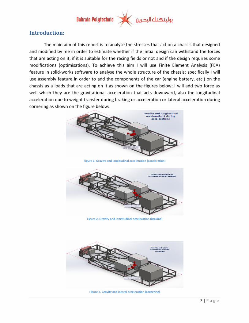
The main aim of this report is to analyse the stresses that act on a chassis that designed
and modified by me in order to estimate whether if the initial design can withstand the forces
that are acting on it, if it is suitable for the racing fields or not and if the design requires some
modifications (optimisations). To achieve this aim I will use Finite Element Analysis (FEA)
feature in solid-works software to analyse the whole structure of the chassis; specifically I will
use assembly feature in order to add the components of the car (engine battery, etc.) on the
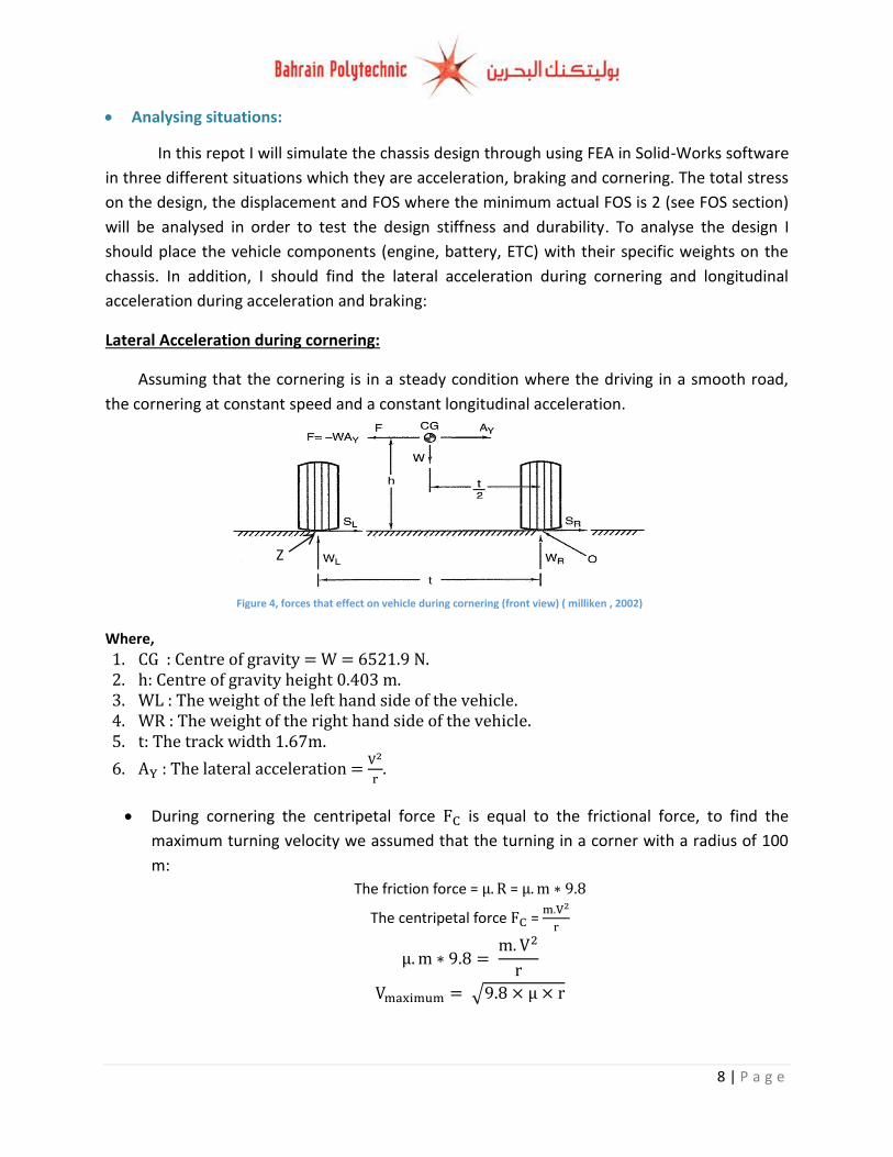
chassis as a loads that are acting on it as shown on the figures below; I will add two force as
well which they are the gravitational acceleration that acts downward, also the longitudinal
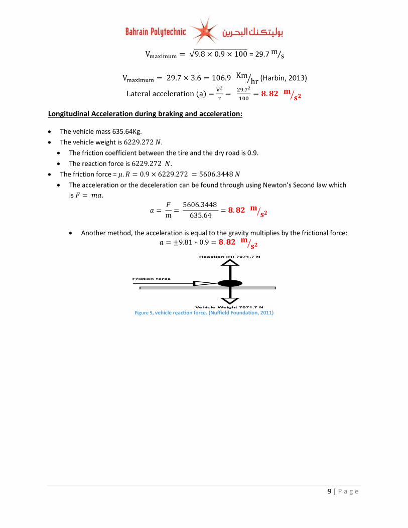
acceleration due to weight transfer during braking or acceleration or lateral acceleration during
cornering as shown on the figure below:
Figure 1, Gravity and longitudinal acceleration (acceleration)
Figure 2, Gravity and longitudinal acceleration (braking)
Figure 3, Gravity and lateral acceleration (cornering)
8 | P a g e
Figure 4, forces that effect on vehicle during cornering (front view) ( milliken , 2002)
Z
Analysing situations:
In this repot I will simulate the chassis design through using FEA in Solid-Works software
in three different situations which they are acceleration, braking and cornering. The total stress
on the design, the displacement and FOS where the minimum actual FOS is 2 (see FOS section)
will be analysed in order to test the design stiffness and durability. To analyse the design I
should place the vehicle components (engine, battery, ETC) with their specific weights on the
chassis. In addition, I should find the lateral acceleration during cornering and longitudinal
acceleration during acceleration and braking:
Lateral Acceleration during cornering:
Assuming that the cornering is in a steady condition where the driving in a smooth road,
the cornering at constant speed and a constant longitudinal acceleration.
Where,
1. : Centre of gravity = W = 6521.9 N. 2. : Centre of gravity height 0.403 m. 3. : The weight of the left hand side of the vehicle. 4. : The weight of the right hand side of the vehicle. 5. : The track width 1.67m.
6. : The lateral acceleration =
.
During cornering the centripetal force is equal to the frictional force, to find the
maximum turning velocity we assumed that the turning in a corner with a radius of 100
m:
The friction force = =
The centripetal force =
√
9 | P a g e
Figure 5, vehicle reaction force. (Nuffield Foundation, 2011)
√ = 29.7 ⁄
⁄ (Harbin, 2013)
Lateral acceleration (a) =
⁄
Longitudinal Acceleration during braking and acceleration:
The vehicle mass 635.64Kg.
The vehicle weight is .
The friction coefficient between the tire and the dry road is 0.9.
The reaction force is .
The friction force =
The acceleration or the deceleration can be found through using Newton’s Second law which
is .
⁄
Another method, the acceleration is equal to the gravity multiplies by the frictional force:
⁄
10 | P a g e
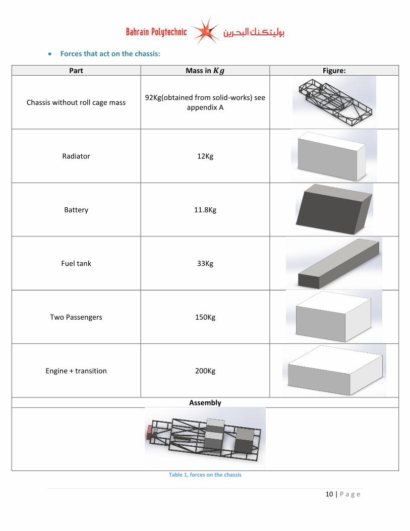
Forces that act on the chassis:
Part Mass in Figure:
Chassis without roll cage mass 92Kg(obtained from solid-works) see
appendix A
Radiator 12Kg
Battery 11.8Kg
Fuel tank 33Kg
Two Passengers 150Kg
Engine + transition 200Kg
Assembly
Table 1, forces on the chassis
11 | P a g e
Tube properties:
Tube size: Location:
25 mm square tube with 2 mall wall thickness
All of the chassis except the side members and roll cage
21 mm square tube with 2 mall wall thickness
For side members only.
38 mm diameter round tube with 3 mm wall thickness
For the roll cage (I did not analyze it due to an
error during simulation) Table 2, tubes dimensions
Tubes material properties:
Material name: AISI 1020
Default failure: Max von Mises Stress
Yield strength: 351.571 (MPa)
Tensile strength: 420.507 (MPa)
Elastic modulus: 200000 (MPa)
Poisson's ratio: 0.29
Mass density: 7900
Shear modulus: 77000 N/(MPa)
Thermal expansion coefficient: 1.5e-005 /Kelvin Table 3, mild steel (AISI 1020) properties (abstained from solid works)
Failure modes:
Static loading:
Static loading is a stationary force or couple applied to a material, and to be stationary
the force or the couple must be constant in the magnitude, in the point or points of application,
and in the direction. There are many examples of static loading forces such as, axial tension or
compression, a shear load, a bending load, or any combination of these. In addition, the
material starts yielding (become permanently distorted) or fail (separated into two pieces or
more) if the applied stress (load) exceeds the material’s strength (UTS). For instance, during
static the chassis is subjected to a bending stress due to the weight of car components (battery,
engine, etc.) that are placed on the chassis; where if the chassis not stiff enough it’s member
(square tubes) will bend during static. In addition, two tests are important for static loading
which they are Creep test and rapture test.
12 | P a g e
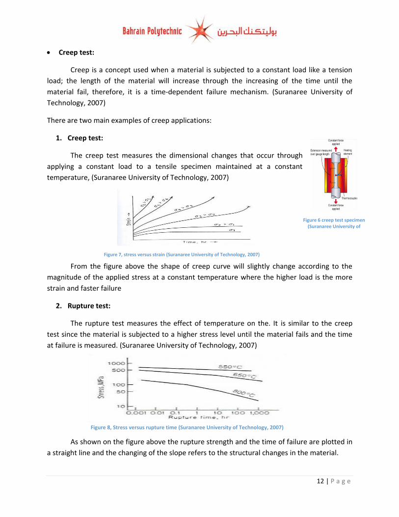
Figure 6 creep test specimen (Suranaree University of
Technology, 2007)
Figure 8, Stress versus rupture time (Suranaree University of Technology, 2007)
Figure 7, stress versus strain (Suranaree University of Technology, 2007)
Creep test:
Creep is a concept used when a material is subjected to a constant load like a tension
load; the length of the material will increase through the increasing of the time until the
material fail, therefore, it is a time-dependent failure mechanism. (Suranaree University of
Technology, 2007)
There are two main examples of creep applications:
1. Creep test:
The creep test measures the dimensional changes that occur through
applying a constant load to a tensile specimen maintained at a constant
temperature, (Suranaree University of Technology, 2007)
From the figure above the shape of creep curve will slightly change according to the
magnitude of the applied stress at a constant temperature where the higher load is the more
strain and faster failure
2. Rupture test:
The rupture test measures the effect of temperature on the. It is similar to the creep
test since the material is subjected to a higher stress level until the material fails and the time
at failure is measured. (Suranaree University of Technology, 2007)
As shown on the figure above the rupture strength and the time of failure are plotted in
a straight line and the changing of the slope refers to the structural changes in the material.
13 | P a g e
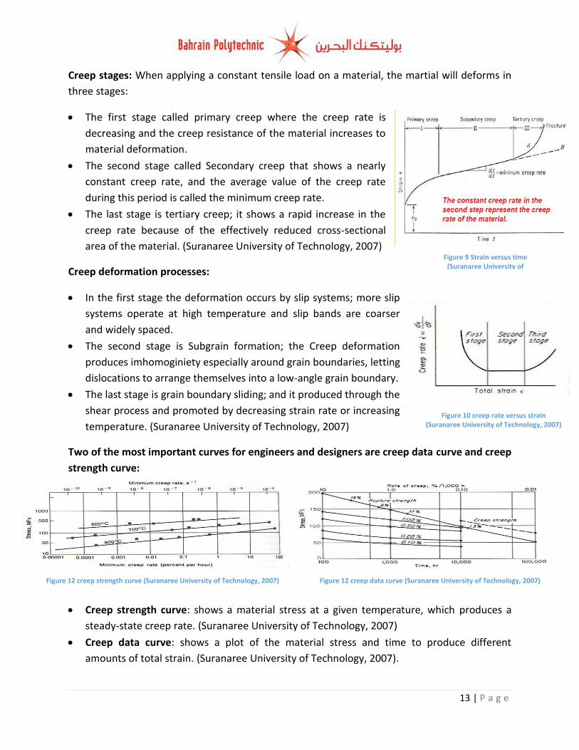
Figure 9 Strain versus time (Suranaree University of
Technology, 2007)
Figure 10 creep rate versus strain (Suranaree University of Technology, 2007)
Creep stages: When applying a constant tensile load on a material, the martial will deforms in
three stages:
The first stage called primary creep where the creep rate is
decreasing and the creep resistance of the material increases to
material deformation.
The second stage called Secondary creep that shows a nearly
constant creep rate, and the average value of the creep rate
during this period is called the minimum creep rate.
The last stage is tertiary creep; it shows a rapid increase in the
creep rate because of the effectively reduced cross-sectional
area of the material. (Suranaree University of Technology, 2007)
Creep deformation processes:
In the first stage the deformation occurs by slip systems; more slip
systems operate at high temperature and slip bands are coarser
and widely spaced.
The second stage is Subgrain formation; the Creep deformation
produces imhomoginiety especially around grain boundaries, letting
dislocations to arrange themselves into a low-angle grain boundary.
The last stage is grain boundary sliding; and it produced through the
shear process and promoted by decreasing strain rate or increasing
temperature. (Suranaree University of Technology, 2007)
Two of the most important curves for engineers and designers are creep data curve and creep
strength curve:
Creep strength curve: shows a material stress at a given temperature, which produces a
steady-state creep rate. (Suranaree University of Technology, 2007)
Creep data curve: shows a plot of the material stress and time to produce different
amounts of total strain. (Suranaree University of Technology, 2007).
Figure 12 creep strength curve (Suranaree University of Technology, 2007) Figure 12 creep data curve (Suranaree University of Technology, 2007)
14 | P a g e
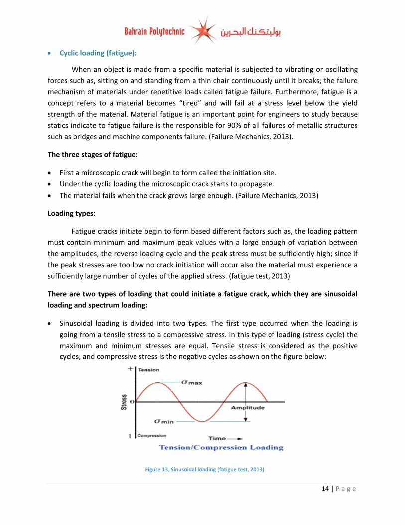
Figure 13, Sinusoidal loading (fatigue test, 2013)
Cyclic loading (fatigue):
When an object is made from a specific material is subjected to vibrating or oscillating
forces such as, sitting on and standing from a thin chair continuously until it breaks; the failure
mechanism of materials under repetitive loads called fatigue failure. Furthermore, fatigue is a
concept refers to a material becomes “tired” and will fail at a stress level below the yield
strength of the material. Material fatigue is an important point for engineers to study because
statics indicate to fatigue failure is the responsible for 90% of all failures of metallic structures
such as bridges and machine components failure. (Failure Mechanics, 2013).
The three stages of fatigue:
First a microscopic crack will begin to form called the initiation site.
Under the cyclic loading the microscopic crack starts to propagate.
The material fails when the crack grows large enough. (Failure Mechanics, 2013)
Loading types:
Fatigue cracks initiate begin to form based different factors such as, the loading pattern
must contain minimum and maximum peak values with a large enough of variation between
the amplitudes, the reverse loading cycle and the peak stress must be sufficiently high; since if
the peak stresses are too low no crack initiation will occur also the material must experience a
sufficiently large number of cycles of the applied stress. (fatigue test, 2013)
There are two types of loading that could initiate a fatigue crack, which they are sinusoidal
loading and spectrum loading:
Sinusoidal loading is divided into two types. The first type occurred when the loading is
going from a tensile stress to a compressive stress. In this type of loading (stress cycle) the
maximum and minimum stresses are equal. Tensile stress is considered as the positive
cycles, and compressive stress is the negative cycles as shown on the figure below:
15 | P a g e
Figure 14, Sinusoidal loading (fatigue test, 2013)
Figure 15, spectrum loading (fatigue test, 2013)
Figure 16, Ferrous and nonferrous S-N curves (S-N curves, 2011)
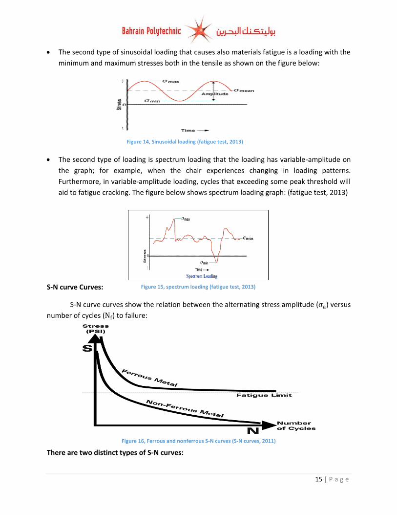
The second type of sinusoidal loading that causes also materials fatigue is a loading with the
minimum and maximum stresses both in the tensile as shown on the figure below:
The second type of loading is spectrum loading that the loading has variable-amplitude on
the graph; for example, when the chair experiences changing in loading patterns.
Furthermore, in variable-amplitude loading, cycles that exceeding some peak threshold will
aid to fatigue cracking. The figure below shows spectrum loading graph: (fatigue test, 2013)
S-N curve Curves:
S-N curve curves show the relation between the alternating stress amplitude ( ) versus
number of cycles ( ) to failure:
There are two distinct types of S-N curves:
16 | P a g e
Figure 17, stress versus strain graph (Tensile properties, 2012)
The first type of S-N curves occurred in ferrous (iron based) alloys like carbon steel, which
the stress amplitude starts decreasing through the increasing number of cycles until the
curve becomes horizontal which means through the increasing number of cycles the stress
will remain the same, therefore the material will not fail, this called fatigue limit or
endurance limit. (the upper curve) (Failure Mechanics, 2013).
The second type of S-N curve occurred in Nonferrous alloys like Aluminium that there is no
fatigue limit for the material, thus the S-N curve continues downwards and fatigue failure
will occur after a certain number of cycles.(the lower curve) (Failure Mechanics, 2013)
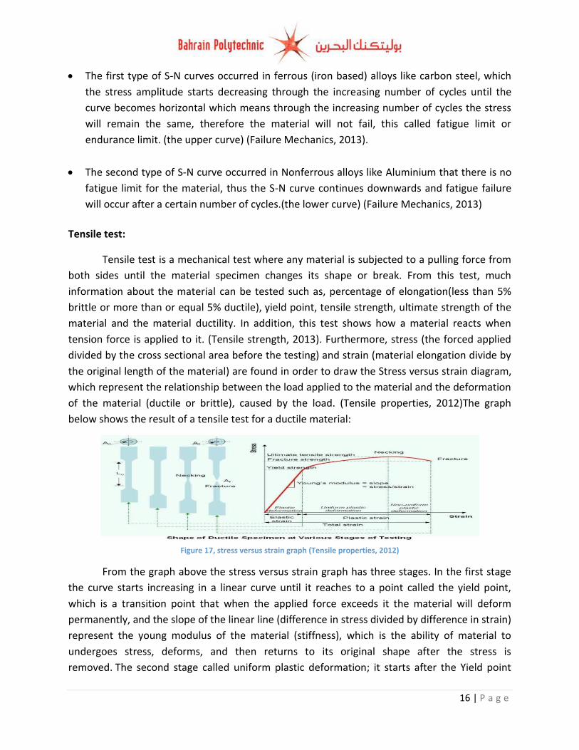
Tensile test:
Tensile test is a mechanical test where any material is subjected to a pulling force from
both sides until the material specimen changes its shape or break. From this test, much
information about the material can be tested such as, percentage of elongation(less than 5%
brittle or more than or equal 5% ductile), yield point, tensile strength, ultimate strength of the
material and the material ductility. In addition, this test shows how a material reacts when
tension force is applied to it. (Tensile strength, 2013). Furthermore, stress (the forced applied
divided by the cross sectional area before the testing) and strain (material elongation divide by
the original length of the material) are found in order to draw the Stress versus strain diagram,
which represent the relationship between the load applied to the material and the deformation
of the material (ductile or brittle), caused by the load. (Tensile properties, 2012)The graph
below shows the result of a tensile test for a ductile material:
From the graph above the stress versus strain graph has three stages. In the first stage
the curve starts increasing in a linear curve until it reaches to a point called the yield point,
which is a transition point that when the applied force exceeds it the material will deform
permanently, and the slope of the linear line (difference in stress divided by difference in strain)
represent the young modulus of the material (stiffness), which is the ability of material to
undergoes stress, deforms, and then returns to its original shape after the stress is
removed. The second stage called uniform plastic deformation; it starts after the Yield point
17 | P a g e
Figure 18, ductile and brittle materials.
where the curve increasing uniformly until it reaches to the highest point of the curve which
represents the ultimate tensile strength (UTS) of the tested material. Furthermore, the
maximum stress level reached in this test (UTS) represents the material ability to withstand
external forces without breaking. The last stage is non-uniform plastic deformation that the
curve starts decreasing until it reaches to the fracture point that the material cut into two
pieces. (tensile, 2012).
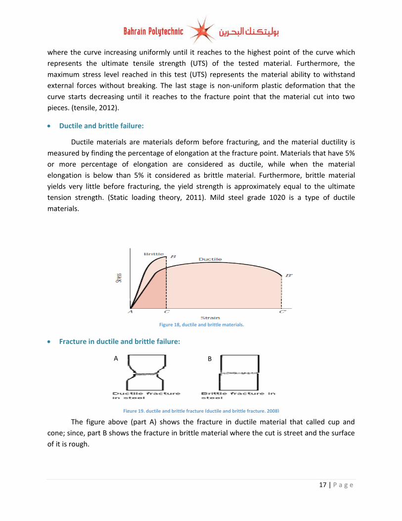
Ductile and brittle failure:
Ductile materials are materials deform before fracturing, and the material ductility is
measured by finding the percentage of elongation at the fracture point. Materials that have 5%
or more percentage of elongation are considered as ductile, while when the material
elongation is below than 5% it considered as brittle material. Furthermore, brittle material
yields very little before fracturing, the yield strength is approximately equal to the ultimate
tension strength. (Static loading theory, 2011). Mild steel grade 1020 is a type of ductile
materials.
Fracture in ductile and brittle failure:
The figure above (part A) shows the fracture in ductile material that called cup and
cone; since, part B shows the fracture in brittle material where the cut is street and the surface
of it is rough.
Figure 19, ductile and brittle fracture (ductile and brittle fracture, 2008)
A B
18 | P a g e
Figure 24. microvoid and shear slip (Ductile Fracture 2, 2013)
Crack Propagation (ductile material):
The crack continues to grow during this stage as a result of repetitive loadings. In ductile
materials the crack propagation occurs in several steps.
Initially as a result of the tensile load, the material stretches and experiences plastic
deformation. Beyond some point the material will begin to neck: (Ductile Fracture 2, 2013):
With continuing stress the material continues to plastically deform and small openings
begin to appear inside the material at the centre of the necked region. These holes are known
micro voids (Ductile Fracture 2, 2013):
The micro voids grow and coalesce from a continuous cavity within the centre of the
necked region. Once the cavity in the centre of the specimen reaches a certain size the sample
will fail by fast fracture (Ductile Fracture 2, 2013):
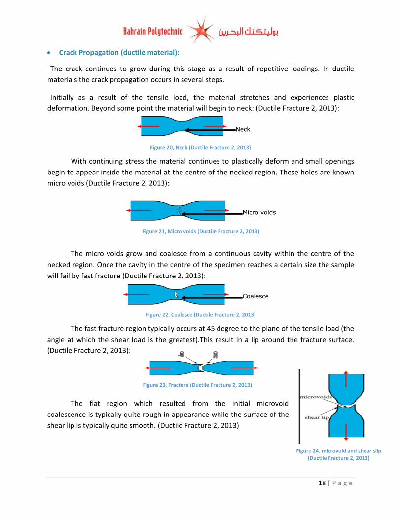
The fast fracture region typically occurs at 45 degree to the plane of the tensile load (the
angle at which the shear load is the greatest).This result in a lip around the fracture surface.
(Ductile Fracture 2, 2013):
The flat region which resulted from the initial microvoid
coalescence is typically quite rough in appearance while the surface of the
shear lip is typically quite smooth. (Ductile Fracture 2, 2013)
Neck
Figure 20, Neck (Ductile Fracture 2, 2013)
Micro voids
Figure 21, Micro voids (Ductile Fracture 2, 2013)
Coalesce
Figure 22, Coalesce (Ductile Fracture 2, 2013)
Figure 23, Fracture (Ductile Fracture 2, 2013)
19 | P a g e
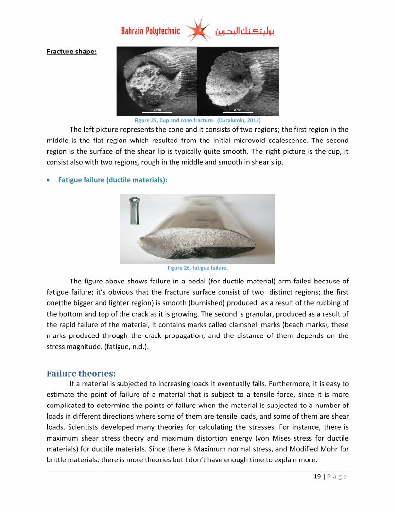
Fracture shape:
The left picture represents the cone and it consists of two regions; the first region in the
middle is the flat region which resulted from the initial microvoid coalescence. The second
region is the surface of the shear lip is typically quite smooth. The right picture is the cup, it
consist also with two regions, rough in the middle and smooth in shear slip.
Fatigue failure (ductile materials):
The figure above shows failure in a pedal (for ductile material) arm failed because of
fatigue failure; it’s obvious that the fracture surface consist of two distinct regions; the first
one(the bigger and lighter region) is smooth (burnished) produced as a result of the rubbing of
the bottom and top of the crack as it is growing. The second is granular, produced as a result of
the rapid failure of the material, it contains marks called clamshell marks (beach marks), these
marks produced through the crack propagation, and the distance of them depends on the
stress magnitude. (fatigue, n.d.).
Failure theories: If a material is subjected to increasing loads it eventually fails. Furthermore, it is easy to
estimate the point of failure of a material that is subject to a tensile force, since it is more
complicated to determine the points of failure when the material is subjected to a number of
loads in different directions where some of them are tensile loads, and some of them are shear
loads. Scientists developed many theories for calculating the stresses. For instance, there is
maximum shear stress theory and maximum distortion energy (von Mises stress for ductile
materials) for ductile materials. Since there is Maximum normal stress, and Modified Mohr for
brittle materials; there is more theories but I don’t have enough time to explain more.
Figure 25, Cup and cone fracture. (Duralumin, 2013)
Figure 26, fatigue failure.
20 | P a g e
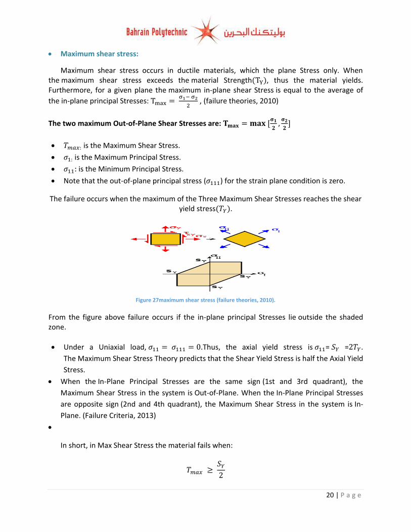
Maximum shear stress:
Maximum shear stress occurs in ductile materials, which the plane Stress only. When the maximum shear stress exceeds the material Strength , thus the material yields. Furthermore, for a given plane the maximum in-plane shear Stress is equal to the average of
the in-plane principal Stresses:
, (failure theories, 2010)
The two maximum Out-of-Plane Shear Stresses are:
is the Maximum Shear Stress.
is the Maximum Principal Stress.
is the Minimum Principal Stress.
Note that the out-of-plane principal stress ( ) for the strain plane condition is zero.
The failure occurs when the maximum of the Three Maximum Shear Stresses reaches the shear yield stress .
From the figure above failure occurs if the in-plane principal Stresses lie outside the shaded zone.
Under a Uniaxial load, .Thus, the axial yield stress is = = .
The Maximum Shear Stress Theory predicts that the Shear Yield Stress is half the Axial Yield
Stress.
When the In-Plane Principal Stresses are the same sign (1st and 3rd quadrant), the
Maximum Shear Stress in the system is Out-of-Plane. When the In-Plane Principal Stresses
are opposite sign (2nd and 4th quadrant), the Maximum Shear Stress in the system is In-
Plane. (Failure Criteria, 2013)
In short, in Max Shear Stress the material fails when:
Figure 27maximum shear stress (failure theories, 2010).
21 | P a g e
Figure 28 Von Mises stress (Failure Criteria, 2013)
Figure 29 Maximum normal stress (Failure Criteria, 2013)
Factor of Safety:
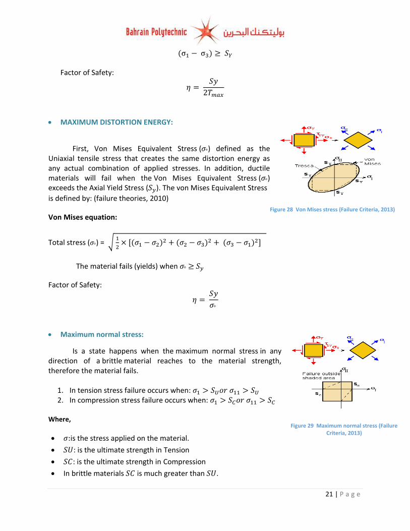
MAXIMUM DISTORTION ENERGY:
First, Von Mises Equivalent Stress ( ) defined as the Uniaxial tensile stress that creates the same distortion energy as any actual combination of applied stresses. In addition, ductile materials will fail when the Von Mises Equivalent Stress ( ) exceeds the Axial Yield Stress ( ). The von Mises Equivalent Stress
is defined by: (failure theories, 2010)
Von Mises equation:
Total stress ( ) = √
The material fails (yields) when
Factor of Safety:
Maximum normal stress:
Is a state happens when the maximum normal stress in any direction of a brittle material reaches to the material strength, therefore the material fails.
1. In tension stress failure occurs when: 2. In compression stress failure occurs when:
Where,
is the stress applied on the material.
: is the ultimate strength in Tension
: is the ultimate strength in Compression
In brittle materials is much greater than .
22 | P a g e
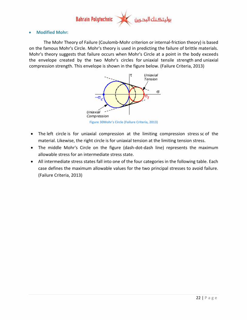
Modified Mohr:
The Mohr Theory of Failure (Coulomb-Mohr criterion or internal-friction theory) is based on the famous Mohr's Circle. Mohr's theory is used in predicting the failure of brittle materials. Mohr's theory suggests that failure occurs when Mohr's Circle at a point in the body exceeds the envelope created by the two Mohr's circles for uniaxial tensile strength and uniaxial compression strength. This envelope is shown in the figure below. (Failure Criteria, 2013)
The left circle is for uniaxial compression at the limiting compression stress sc of the
material. Likewise, the right circle is for uniaxial tension at the limiting tension stress.
The middle Mohr's Circle on the figure (dash-dot-dash line) represents the maximum
allowable stress for an intermediate stress state.
All intermediate stress states fall into one of the four categories in the following table. Each
case defines the maximum allowable values for the two principal stresses to avoid failure.
(Failure Criteria, 2013)
Figure 30Mohr's Circle (Failure Criteria, 2013)
23 | P a g e
Factor of safety\ displacement:
The factor of safety (FOS) can be estimated through specifying five elements which they are; the properties of the material, the applied stresses, geometry, failure analysis and the desired reliability.
Estimating the contribution for the material :
The properties of the material (the specific chosen material for the chassis) will be obtained from Solid Works software or from a trusted internet source like (mat-web). Therefore, all of the properties are well known; though we will not do a special test to ensure the properties of the specific chosen material. However, the supplier do not grantee that the tubing sections have a constant thickness where some points of the tubes may be thinker or thinner than the spiced thickness. In addition, the material can expose to some of the environmental conditions such as, corrosion and rust that lead to the material wear. Therefore we will put the safety factor as 1.1
Estimating the contribution for the load stress :
In this part the nature of the loads that act on the vehicle during static, acceleration, declaration, cornering and bumping are well known as a separate situation. In combined situations like acceleration and cornering in the same time or bumping and cornering in the same time the loads are not well known. Therefore we will put the safety factor as 1.2.
Estimating the contribution for geometry :
The students will build the chassis manually by their self and due to the lack of welding experience for the reason that most students did not weld anything before or study a welding course; therefore, there is a big possible that the manufacturing dimensions will be out of tolerances and not closely held. Therefore we will put the geometry safety factor as 1.15.
Estimating the contribution for failure analysis :
The failure analysis is not well developed where we did not calculate the failure due to cumulative damage or fatigue stresses. Therefore we will put the failure analysis safety factor as 1.2.
24 | P a g e
Estimating the contribution for reliability :
Solid works software uses thousands of equations to analyse the stress on each small part
of the wishbone (software splits the wishbone into thousands of meshes); therefore, we can
rely on sold works simulation; since it’s still theoretical calculations Therefore I will put the 1.1
as safety factor for reliability.
Therefore,
Displacement:
The allowable range of displacement for the chassis design should be 1 mm or lower; I
selected 1 mm as a maximum displacement for several reasons first is to provide stable driving
without any sudden shocks (good for handling), also, to do not effect on the suspension
geometry (camber, caster and toe) due to the chassis is connected with suspension system so
the large displacement will effect on the suspension geometry which leads to tires wear and the
instability of the vehicle as well. Furthermore, I select 1 mm to avoid the design failure.
Finite Element Analysis:
Definition:
Finite Element Analysis (FEA) is computer program uses a finite element technique to study
a design with a specific material; it analyses how the applied loads (stresses) will effect on the
design through giving specific results (graphs and tables). FEA analysis is done through
generating a mesh of points in a shape of the design that has information about the used
material properties and the design at each point for the doing the analysis. The benefits of
(FEA) are, it can assist in finding the design reactions against the stresses that are acting on the
design, it can analyse the effect of heat transfer, fatigue and vibration as well. The main benefit
of (FEA) it can help in finding the weakness points in the design before manufacturing it, and
determining the design required modifications to meet the design requirements
(specifications). (Introduction to Finite Element Analysis, 2008).
25 | P a g e
FEA types:
There are two methods can be used for the analysis, modelling and modelling;
the modelling is simple and lets the analysis to be run on normal computers
(recommended for building 30 computers), however, it gives less accurate results. Since, the
modelling, generates more accurate results (requires fast computers with high
specifications such as Ram, processor, etc.). In both modelling methods, the programmers can
add numerous functions in order to make the system behave linearly or non-linearly. The linear
systems are less complex; typically they do not take into account the plastic deformation. The
non-linear systems analyse the plastic deformation, test a material in a specific design in all the
way to fracture, etc. (Introduction to Finite Element Analysis, 2008)
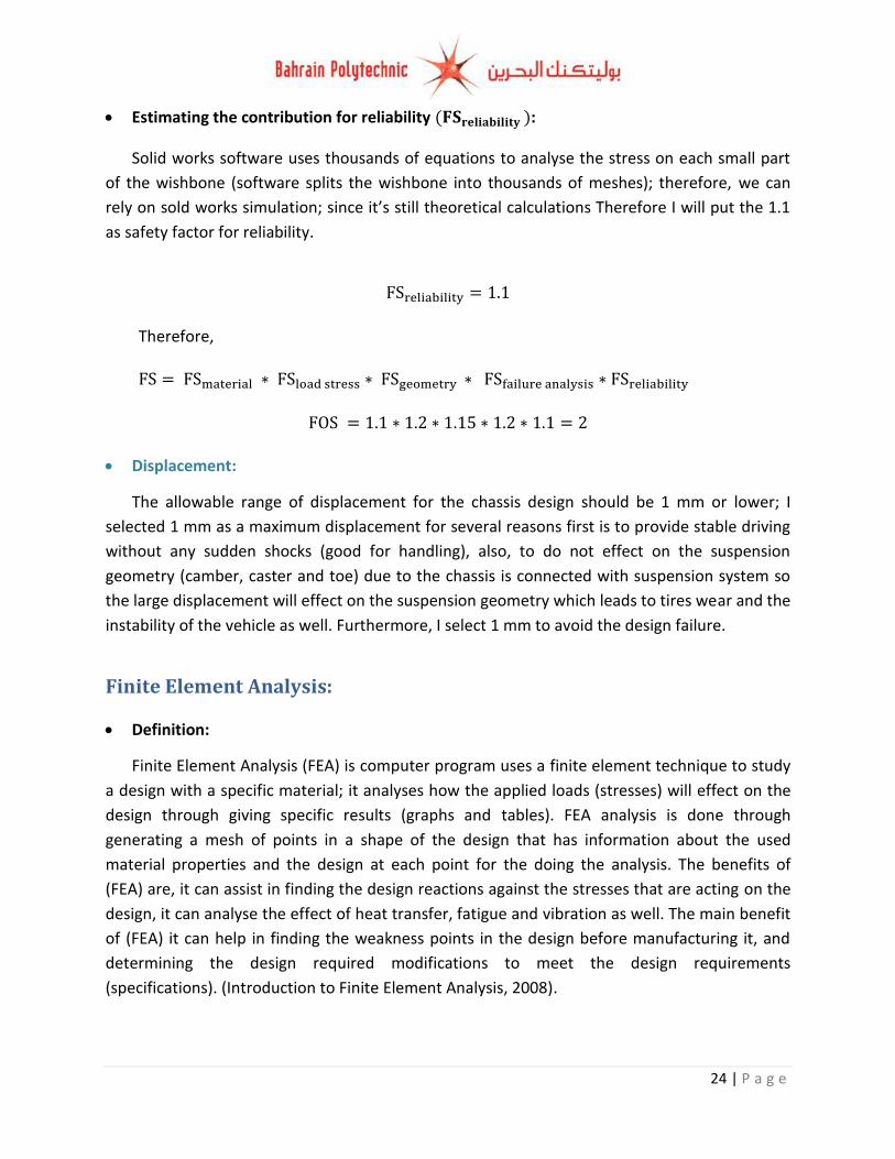
Meshing system in FEA:
In FEA the software (any software applies FEA) uses very complicated system of points
called nodes; these nodes create a mesh on the tested design as shown on figure below. The
mesh is programmed to have the material and design properties which describe how the
structure will react to the stress that the design will expose to. (Introduction to Finite Element
Analysis, 2008)
The loads that can be applied in FEA:
1. Pressure, thermal, centrifugal static loads and the gravity.
2. Thermal loads that are from solution of heat transfer analysis.
3. Convection and heat flux.
4. Gravity dynamic loads.
5. ETC (based on the used software). (Introduction to Finite Element Analysis, 2008)
FEA gives a results for maximization and minimisation of:
1. Displacement, velocity, acceleration and force.
2. Volume, temperature, mass.
3. Stress and strain energy.
4. Synthetic (User defined). (Introduction to Finite Element Analysis, 2008)
Figure 31, Meshing system (FEA). (sciepub, n.d.)
26 | P a g e
Chassis (FEA) steps:
In order to analyse the chassis and the stress that are acting on it, we should do some steps
in order to get right simulation without any error; the table below shows the steps for doing the
FEA in solid-works:
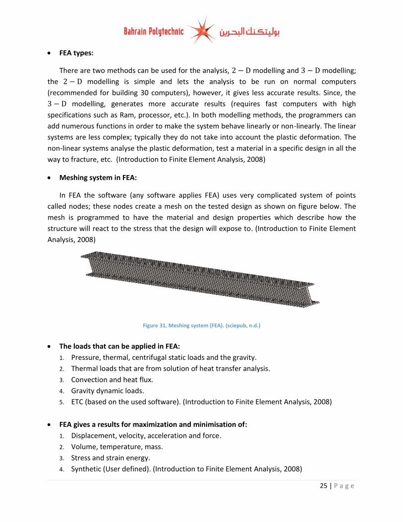
1. Applying the material to the chassis:
Before doing this step we should go to new study than static.
Click on apply material (1) than Choose the required material (2), and finally apply the changes than close the window (3).
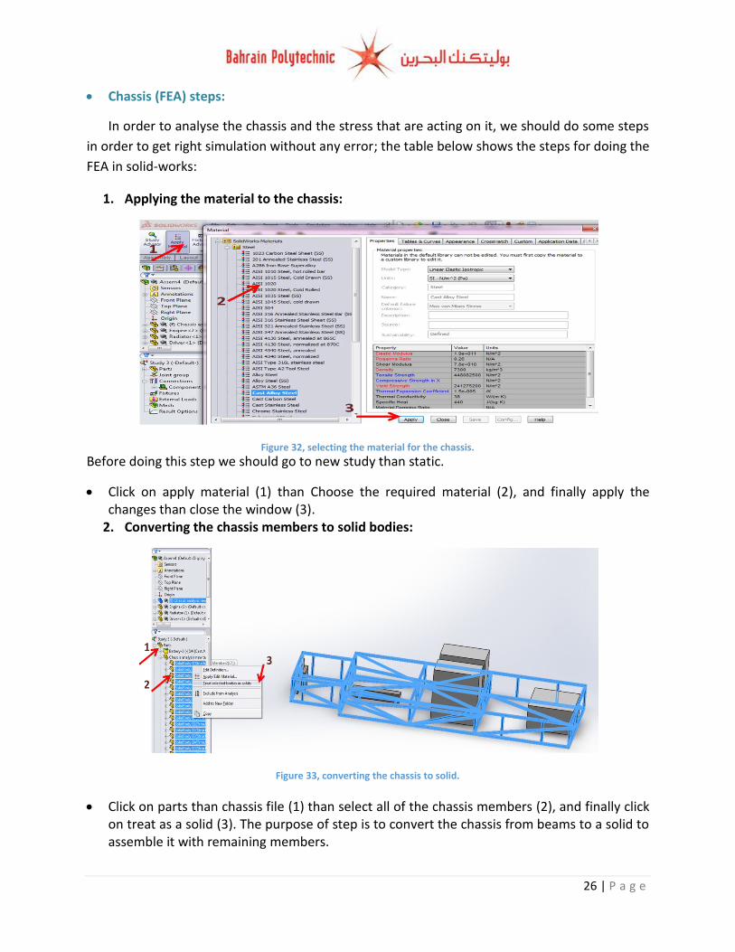
2. Converting the chassis members to solid bodies:
Click on parts than chassis file (1) than select all of the chassis members (2), and finally click on treat as a solid (3). The purpose of step is to convert the chassis from beams to a solid to assemble it with remaining members.
Figure 32, selecting the material for the chassis.
Figure 33, converting the chassis to solid.
27 | P a g e
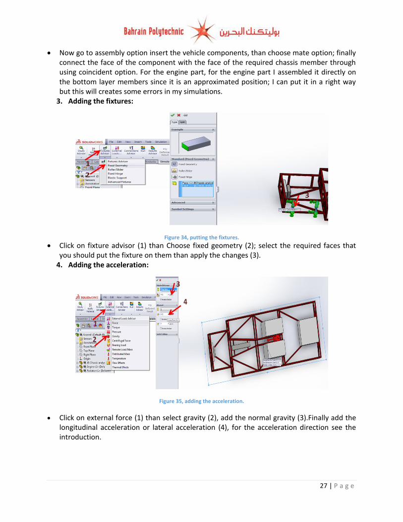
Now go to assembly option insert the vehicle components, than choose mate option; finally connect the face of the component with the face of the required chassis member through using coincident option. For the engine part, for the engine part I assembled it directly on the bottom layer members since it is an approximated position; I can put it in a right way but this will creates some errors in my simulations.
3. Adding the fixtures:
Click on fixture advisor (1) than Choose fixed geometry (2); select the required faces that you should put the fixture on them than apply the changes (3).
4. Adding the acceleration:
Click on external force (1) than select gravity (2), add the normal gravity (3).Finally add the longitudinal acceleration or lateral acceleration (4), for the acceleration direction see the introduction.
Figure 34, putting the fixtures.
Figure 35, adding the acceleration.
28 | P a g e
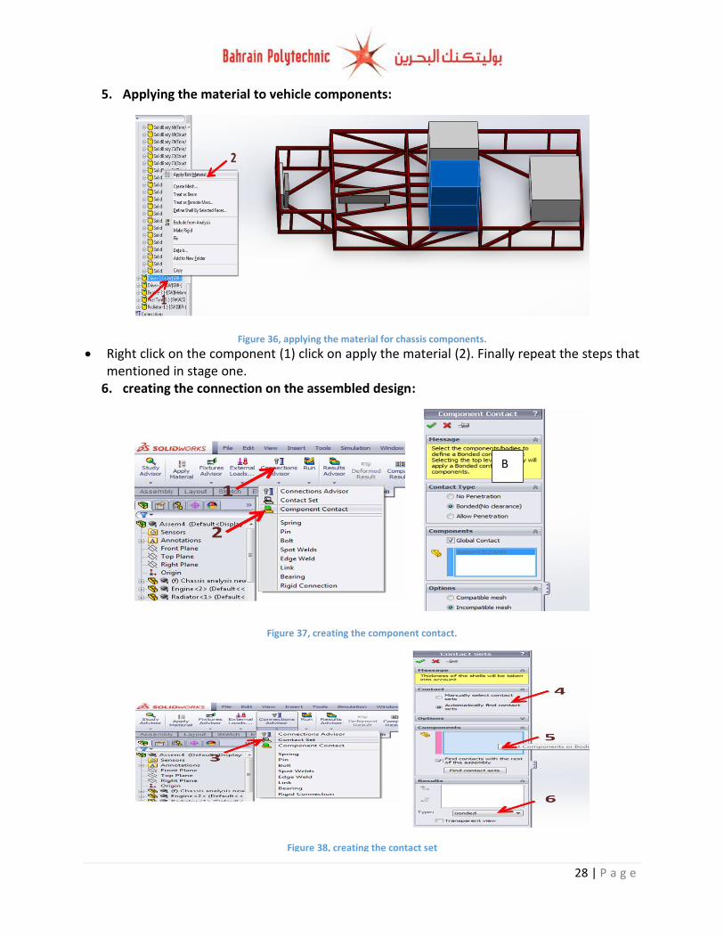
5. Applying the material to vehicle components:
Right click on the component (1) click on apply the material (2). Finally repeat the steps that mentioned in stage one.
6. creating the connection on the assembled design:
Figure 36, applying the material for chassis components.
Figure 38, creating the contact set
Figure 37, creating the component contact.
B
29 | P a g e
Click on connection adviser (1) than select component contact (2); check the box exactly as shown on part B in figure 33.click contact set(3), select automatic find contact set(4), select the whole chassis and click find contact set(5), and finally chose bonded than apply the changes (6).
The purpose of the two steps (contact set and component contact) is to connect all of the chassis members together, and to connect the chassis with the assembled components in order to mesh the component and getting the simulation without any error.
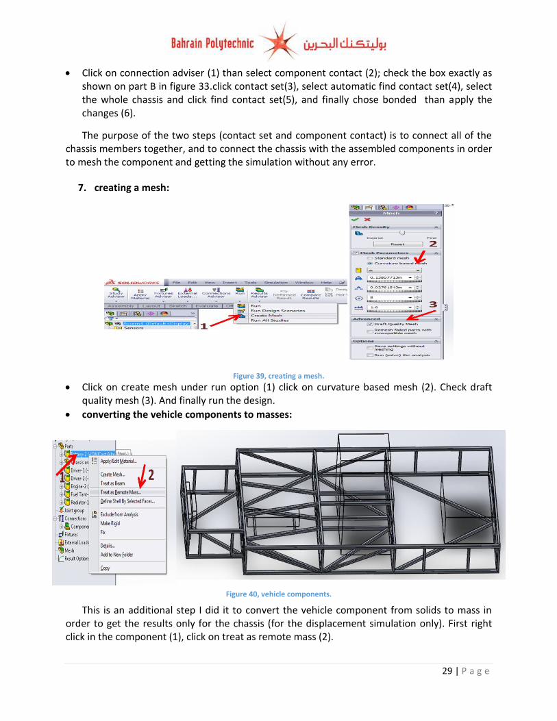
7. creating a mesh:
Click on create mesh under run option (1) click on curvature based mesh (2). Check draft quality mesh (3). And finally run the design.
converting the vehicle components to masses:
This is an additional step I did it to convert the vehicle component from solids to mass in order to get the results only for the chassis (for the displacement simulation only). First right click in the component (1), click on treat as remote mass (2).
Figure 39, creating a mesh.
Figure 40, vehicle components.
30 | P a g e
Chassis Finite Element Analysis:
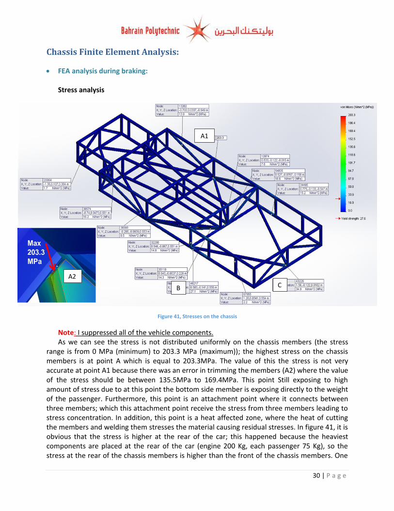
FEA analysis during braking: Stress analysis
Note: I suppressed all of the vehicle components. As we can see the stress is not distributed uniformly on the chassis members (the stress
range is from 0 MPa (minimum) to 203.3 MPa (maximum)); the highest stress on the chassis members is at point A which is equal to 203.3MPa. The value of this the stress is not very accurate at point A1 because there was an error in trimming the members (A2) where the value of the stress should be between 135.5MPa to 169.4MPa. This point Still exposing to high amount of stress due to at this point the bottom side member is exposing directly to the weight of the passenger. Furthermore, this point is an attachment point where it connects between three members; which this attachment point receive the stress from three members leading to stress concentration. In addition, this point is a heat affected zone, where the heat of cutting the members and welding them stresses the material causing residual stresses. In figure 41, it is obvious that the stress is higher at the rear of the car; this happened because the heaviest components are placed at the rear of the car (engine 200 Kg, each passenger 75 Kg), so the stress at the rear of the chassis members is higher than the front of the chassis members. One
Figure 41, Stresses on the chassis
A2
A1
B C
31 | P a g e
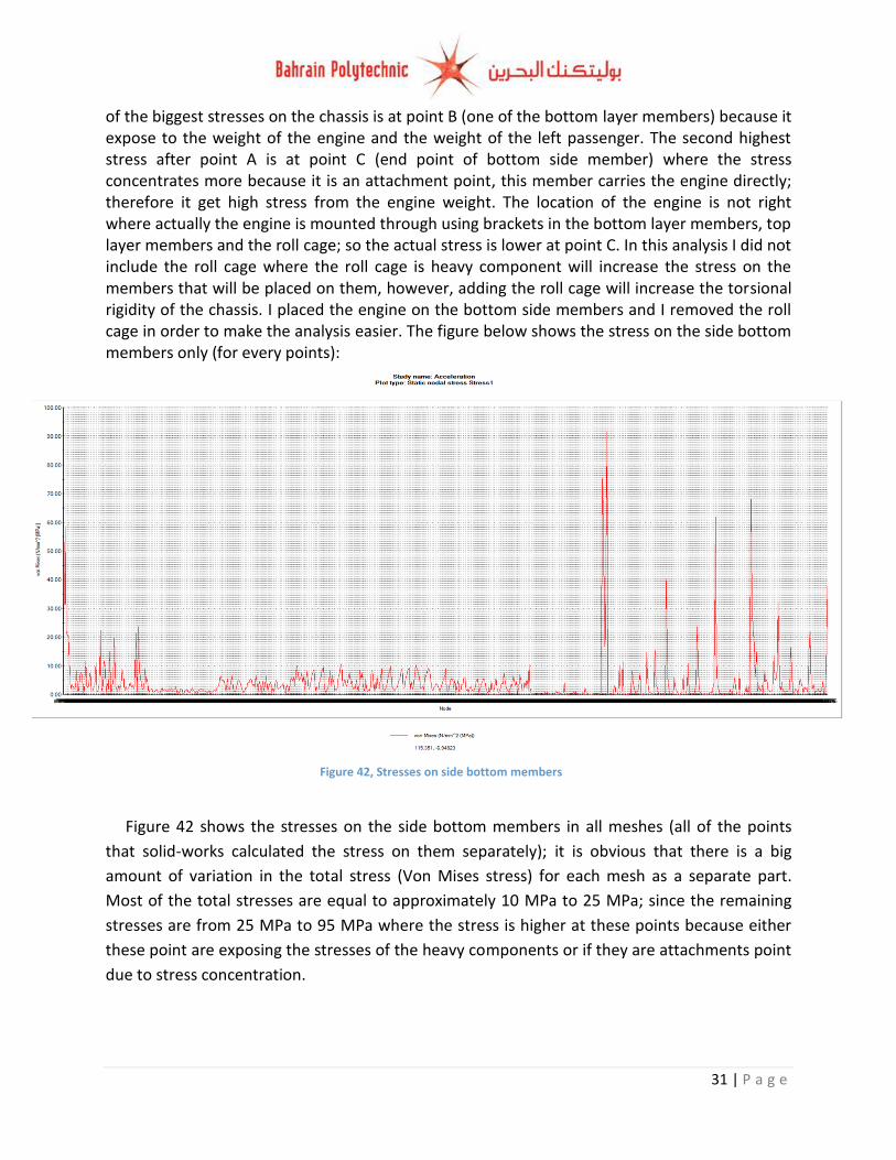
of the biggest stresses on the chassis is at point B (one of the bottom layer members) because it expose to the weight of the engine and the weight of the left passenger. The second highest stress after point A is at point C (end point of bottom side member) where the stress concentrates more because it is an attachment point, this member carries the engine directly; therefore it get high stress from the engine weight. The location of the engine is not right where actually the engine is mounted through using brackets in the bottom layer members, top layer members and the roll cage; so the actual stress is lower at point C. In this analysis I did not include the roll cage where the roll cage is heavy component will increase the stress on the members that will be placed on them, however, adding the roll cage will increase the torsional rigidity of the chassis. I placed the engine on the bottom side members and I removed the roll cage in order to make the analysis easier. The figure below shows the stress on the side bottom members only (for every points):
Figure 42 shows the stresses on the side bottom members in all meshes (all of the points
that solid-works calculated the stress on them separately); it is obvious that there is a big
amount of variation in the total stress (Von Mises stress) for each mesh as a separate part.
Most of the total stresses are equal to approximately 10 MPa to 25 MPa; since the remaining
stresses are from 25 MPa to 95 MPa where the stress is higher at these points because either
these point are exposing the stresses of the heavy components or if they are attachments point
due to stress concentration.
Figure 42, Stresses on side bottom members
32 | P a g e
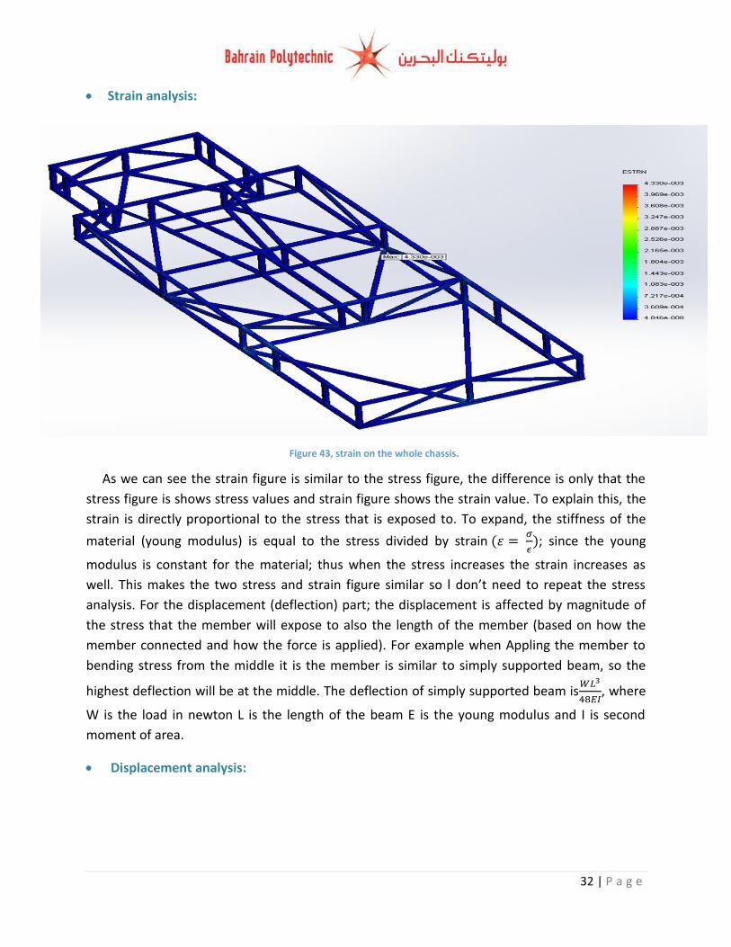
Strain analysis:
As we can see the strain figure is similar to the stress figure, the difference is only that the
stress figure is shows stress values and strain figure shows the strain value. To explain this, the
strain is directly proportional to the stress that is exposed to. To expand, the stiffness of the
material (young modulus) is equal to the stress divided by strain
; since the young
modulus is constant for the material; thus when the stress increases the strain increases as
well. This makes the two stress and strain figure similar so l don’t need to repeat the stress
analysis. For the displacement (deflection) part; the displacement is affected by magnitude of
the stress that the member will expose to also the length of the member (based on how the
member connected and how the force is applied). For example when Appling the member to
bending stress from the middle it is the member is similar to simply supported beam, so the
highest deflection will be at the middle. The deflection of simply supported beam is
, where
W is the load in newton L is the length of the beam E is the young modulus and I is second
moment of area.
Displacement analysis:
Figure 43, strain on the whole chassis.
33 | P a g e
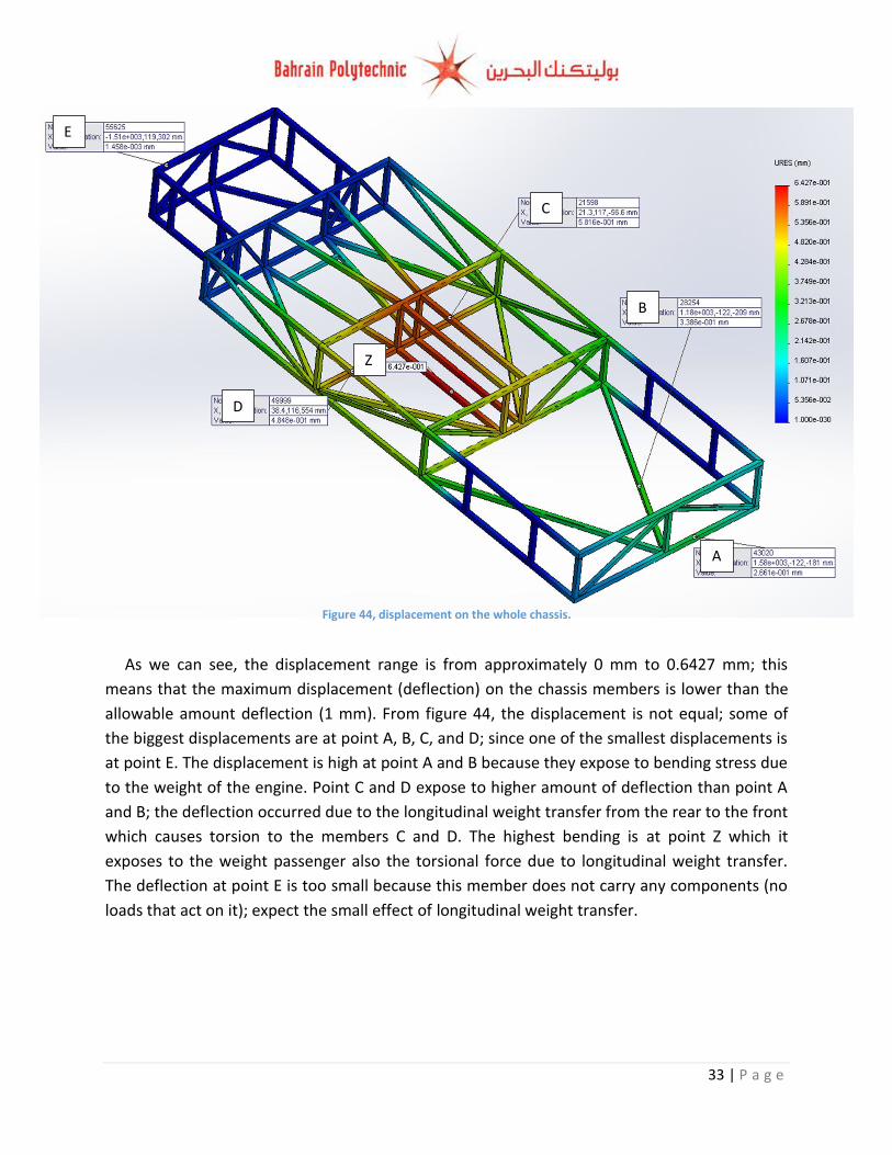
As we can see, the displacement range is from approximately 0 mm to 0.6427 mm; this
means that the maximum displacement (deflection) on the chassis members is lower than the
allowable amount deflection (1 mm). From figure 44, the displacement is not equal; some of
the biggest displacements are at point A, B, C, and D; since one of the smallest displacements is
at point E. The displacement is high at point A and B because they expose to bending stress due
to the weight of the engine. Point C and D expose to higher amount of deflection than point A
and B; the deflection occurred due to the longitudinal weight transfer from the rear to the front
which causes torsion to the members C and D. The highest bending is at point Z which it
exposes to the weight passenger also the torsional force due to longitudinal weight transfer.
The deflection at point E is too small because this member does not carry any components (no
loads that act on it); expect the small effect of longitudinal weight transfer.
Figure 44, displacement on the whole chassis.
A
C
B
D
E
Z
34 | P a g e
Figure 45, FOS during braking
A
C
B D
E
F
Z
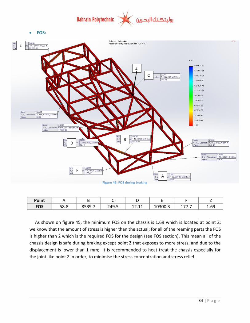
FOS:
Point A B C D E F Z
FOS 58.8 8539.7 249.5 12.11 10300.3 177.7 1.69
As shown on figure 45, the minimum FOS on the chassis is 1.69 which is located at point Z;
we know that the amount of stress is higher than the actual; for all of the reaming parts the FOS
is higher than 2 which is the required FOS for the design (see FOS section). This mean all of the
chassis design is safe during braking except point Z that exposes to more stress, and due to the
displacement is lower than 1 mm; it is recommended to heat treat the chassis especially for
the joint like point Z in order, to minimise the stress concentration and stress relief.
35 | P a g e
FEA analysis during Acceleration:
Stress analysis
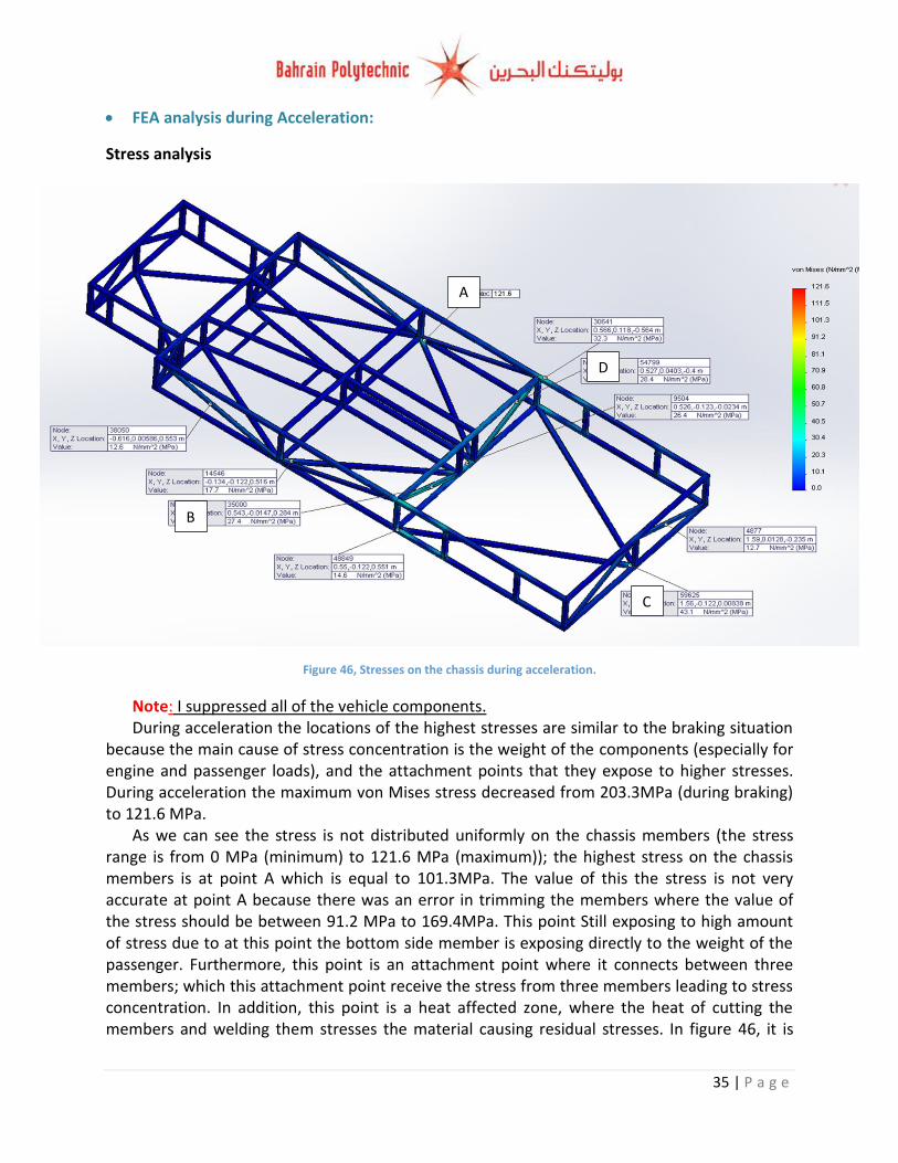
Note: I suppressed all of the vehicle components. During acceleration the locations of the highest stresses are similar to the braking situation
because the main cause of stress concentration is the weight of the components (especially for engine and passenger loads), and the attachment points that they expose to higher stresses. During acceleration the maximum von Mises stress decreased from 203.3MPa (during braking) to 121.6 MPa.
As we can see the stress is not distributed uniformly on the chassis members (the stress range is from 0 MPa (minimum) to 121.6 MPa (maximum)); the highest stress on the chassis members is at point A which is equal to 101.3MPa. The value of this the stress is not very accurate at point A because there was an error in trimming the members where the value of the stress should be between 91.2 MPa to 169.4MPa. This point Still exposing to high amount of stress due to at this point the bottom side member is exposing directly to the weight of the passenger. Furthermore, this point is an attachment point where it connects between three members; which this attachment point receive the stress from three members leading to stress concentration. In addition, this point is a heat affected zone, where the heat of cutting the members and welding them stresses the material causing residual stresses. In figure 46, it is
Figure 46, Stresses on the chassis during acceleration.
A
D
C
B
36 | P a g e
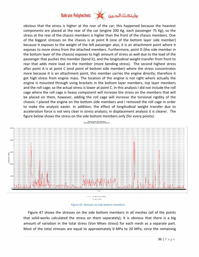
obvious that the stress is higher at the rear of the car; this happened because the heaviest components are placed at the rear of the car (engine 200 Kg, each passenger 75 Kg), so the stress at the rear of the chassis members is higher than the front of the chassis members. One of the biggest stresses on the chassis is at point B (one of the bottom layer side member) because it exposes to the weight of the left passenger also; it is an attachment point where it exposes to more stress from the attached members. Furthermore, point D (the side member in the bottom layer of the chassis) exposes to high amount of stress as well due to the load of the passenger that pushes this member (bend it), and the longitudinal weight transfer from front to rear that adds more load on the member (more bending stress). The second highest stress after point A is at point C (end point of bottom side member) where the stress concentrates more because it is an attachment point, this member carries the engine directly; therefore it get high stress from engine mass. The location of the engine is not right where actually the engine is mounted through using brackets in the bottom layer members, top layer members and the roll cage; so the actual stress is lower at point C. In this analysis I did not include the roll cage where the roll cage is heavy component will increase the stress on the members that will be placed on them, however, adding the roll cage will increase the torsional rigidity of the chassis. I placed the engine on the bottom side members and I removed the roll cage in order to make the analysis easier. In addition, the effect of longitudinal weight transfer due to acceleration force is not very clear in stress analysis; in displacement analysis it is clearer. The figure below shows the stress on the side bottom members only (for every points):
Figure 47 shows the stresses on the side bottom members in all meshes (all of the points
that solid-works calculated the stress on them separately); it is obvious that there is a big
amount of variation in the total stress (Von Mises stress) for each mesh as a separate part.
Most of the total stresses are equal to approximately 0 MPa to 20 MPa; since the remaining
Figure 47, Stresses on side bottom members
37 | P a g e
stresses are from 25 MPa to 95 MPa where the stress is higher at these points because either
these point are exposing the stresses of the heavy components or if they are attachments point
due to stress concentration.
Displacement analysis:
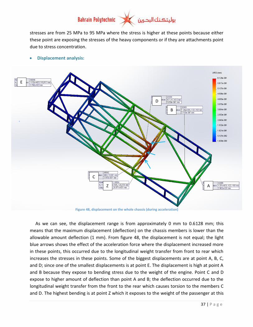
As we can see, the displacement range is from approximately 0 mm to 0.6128 mm; this
means that the maximum displacement (deflection) on the chassis members is lower than the
allowable amount deflection (1 mm). From figure 48, the displacement is not equal; the light
blue arrows shows the effect of the acceleration force where the displacement increased more
in these points, this occurred due to the longitudinal weight transfer from front to rear which
increases the stresses in these points. Some of the biggest displacements are at point A, B, C,
and D; since one of the smallest displacements is at point E. The displacement is high at point A
and B because they expose to bending stress due to the weight of the engine. Point C and D
expose to higher amount of deflection than point A and B; the deflection occurred due to the
longitudinal weight transfer from the front to the rear which causes torsion to the members C
and D. The highest bending is at point Z which it exposes to the weight of the passenger at this
Figure 48, displacement on the whole chassis (during acceleration)
A
D
B
C
E
Z
38 | P a g e
Figure 49, FOS during acceleration
A
C
B
D
E
F
Z
point, and point Z expose to more bending force due to longitudinal weight transfer. The
deflection at point E is too small because this member does not carry any components (no
loads that act on it); expect the small effect of longitudinal weight transfer.
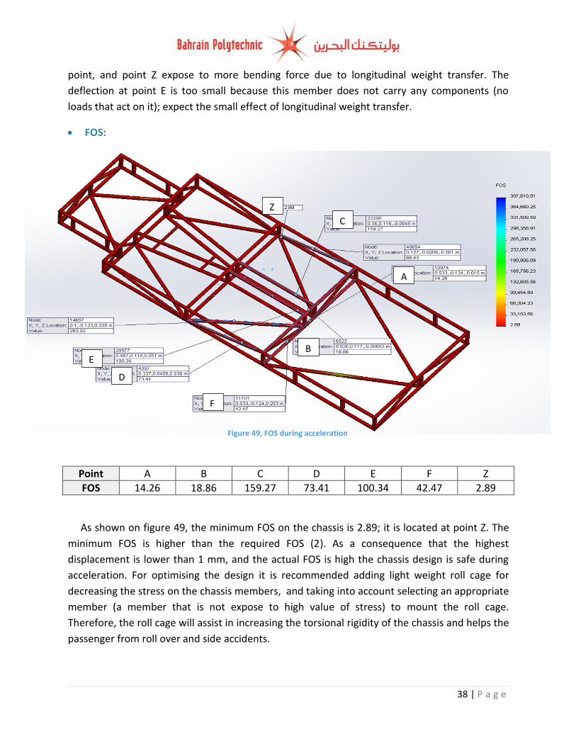
FOS:
Point A B C D E F Z
FOS 14.26 18.86 159.27 73.41 100.34 42.47 2.89
As shown on figure 49, the minimum FOS on the chassis is 2.89; it is located at point Z. The
minimum FOS is higher than the required FOS (2). As a consequence that the highest
displacement is lower than 1 mm, and the actual FOS is high the chassis design is safe during
acceleration. For optimising the design it is recommended adding light weight roll cage for
decreasing the stress on the chassis members, and taking into account selecting an appropriate
member (a member that is not expose to high value of stress) to mount the roll cage.
Therefore, the roll cage will assist in increasing the torsional rigidity of the chassis and helps the
passenger from roll over and side accidents.

39 | P a g e
FEA analysis during Cornering: Stress analysis
Note: I suppressed all of the vehicle components. As we can see the stress is not distributed uniformly on the chassis members (the stress
range is from 0 MPa (minimum) to 219.2 MPa (maximum)); the highest stress on the chassis members is at point A which is equal to 219.2MPa. The value of this the stress is not very accurate at point A1 because there was an error in trimming the members (A2) where the value of the stress should be between 146.1 MPa to 164.4MPa (I discovered the new error in the cornering situation). Therefore, for future analysis I need to double check the trims, and try to fix them if possible for getting more accurate results. This point is still exposing to high amount of stress due to at this point the bottom side member is exposing directly to the weight of the engine. Furthermore, this point is an attachment point where it connects between three members; which this attachment point receive the stress from three members leading to stress concentration. In addition, this point is a heat affected zone, where the heat of cutting the members and welding them stresses the material causing residual stresses. In figure 50, it is obvious that the stress is higher at the rear of the car; this happened because the heaviest components are placed at the rear of the car (engine 200 Kg, each passenger 75 Kg), so the stresses at the rear of the chassis members are higher than the stress on the front of the chassis members.
Figure 50, Stresses on the chassis
A2 A1
B
C
D
40 | P a g e
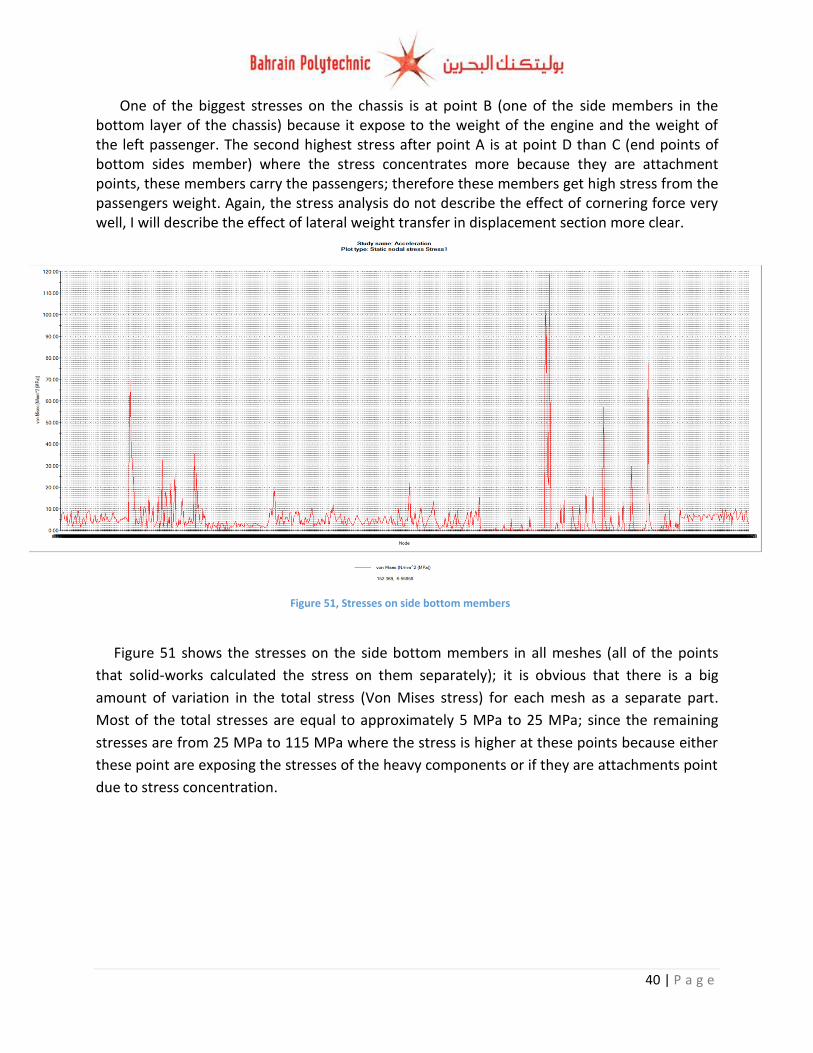
One of the biggest stresses on the chassis is at point B (one of the side members in the bottom layer of the chassis) because it expose to the weight of the engine and the weight of the left passenger. The second highest stress after point A is at point D than C (end points of bottom sides member) where the stress concentrates more because they are attachment points, these members carry the passengers; therefore these members get high stress from the passengers weight. Again, the stress analysis do not describe the effect of cornering force very well, I will describe the effect of lateral weight transfer in displacement section more clear.
Figure 51 shows the stresses on the side bottom members in all meshes (all of the points
that solid-works calculated the stress on them separately); it is obvious that there is a big
amount of variation in the total stress (Von Mises stress) for each mesh as a separate part.
Most of the total stresses are equal to approximately 5 MPa to 25 MPa; since the remaining
stresses are from 25 MPa to 115 MPa where the stress is higher at these points because either
these point are exposing the stresses of the heavy components or if they are attachments point
due to stress concentration.
Figure 51, Stresses on side bottom members
41 | P a g e
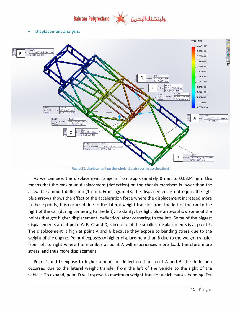
Displacement analysis:
As we can see, the displacement range is from approximately 0 mm to 0.6824 mm; this
means that the maximum displacement (deflection) on the chassis members is lower than the
allowable amount deflection (1 mm). From figure 48, the displacement is not equal; the light
blue arrows shows the effect of the acceleration force where the displacement increased more
in these points, this occurred due to the lateral weight transfer from the left of the car to the
right of the car (during cornering to the left). To clarify, the light blue arrows show some of the
points that got higher displacement (deflection) after cornering to the left. Some of the biggest
displacements are at point A, B, C, and D; since one of the smallest displacements is at point E.
The displacement is high at point A and B because they expose to bending stress due to the
weight of the engine. Point A exposes to higher displacement than B due to the weight transfer
from left to right where the member at point A will experiences more load, therefore more
stress, and thus more displacement.
Point C and D expose to higher amount of deflection than point A and B; the deflection
occurred due to the lateral weight transfer from the left of the vehicle to the right of the
vehicle. To expand, point D will expose to maximum weight transfer which causes bending. For
Figure 52, displacement on the whole chassis (during acceleration)
A
D
B
C
E
Z
42 | P a g e
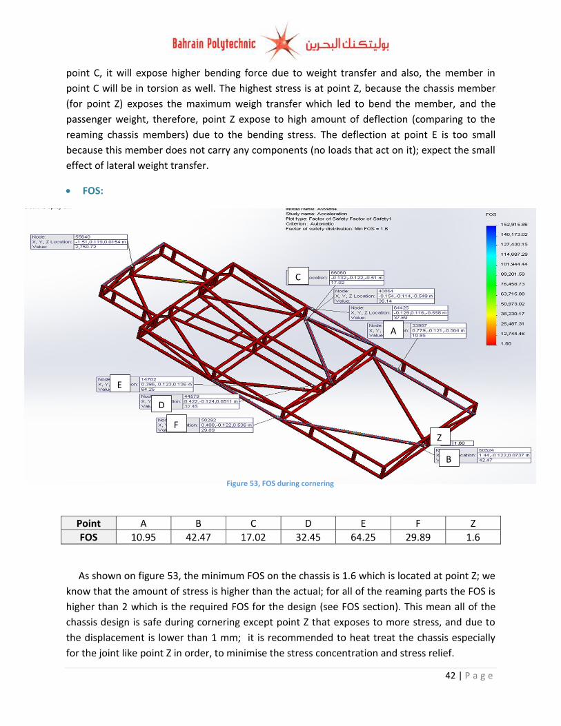
Figure 53, FOS during cornering
A
C
B
D
E
F
Z
point C, it will expose higher bending force due to weight transfer and also, the member in
point C will be in torsion as well. The highest stress is at point Z, because the chassis member
(for point Z) exposes the maximum weigh transfer which led to bend the member, and the
passenger weight, therefore, point Z expose to high amount of deflection (comparing to the
reaming chassis members) due to the bending stress. The deflection at point E is too small
because this member does not carry any components (no loads that act on it); expect the small
effect of lateral weight transfer.
FOS:
Point A B C D E F Z
FOS 10.95 42.47 17.02 32.45 64.25 29.89 1.6
As shown on figure 53, the minimum FOS on the chassis is 1.6 which is located at point Z; we
know that the amount of stress is higher than the actual; for all of the reaming parts the FOS is
higher than 2 which is the required FOS for the design (see FOS section). This mean all of the
chassis design is safe during cornering except point Z that exposes to more stress, and due to
the displacement is lower than 1 mm; it is recommended to heat treat the chassis especially
for the joint like point Z in order, to minimise the stress concentration and stress relief.
43 | P a g e
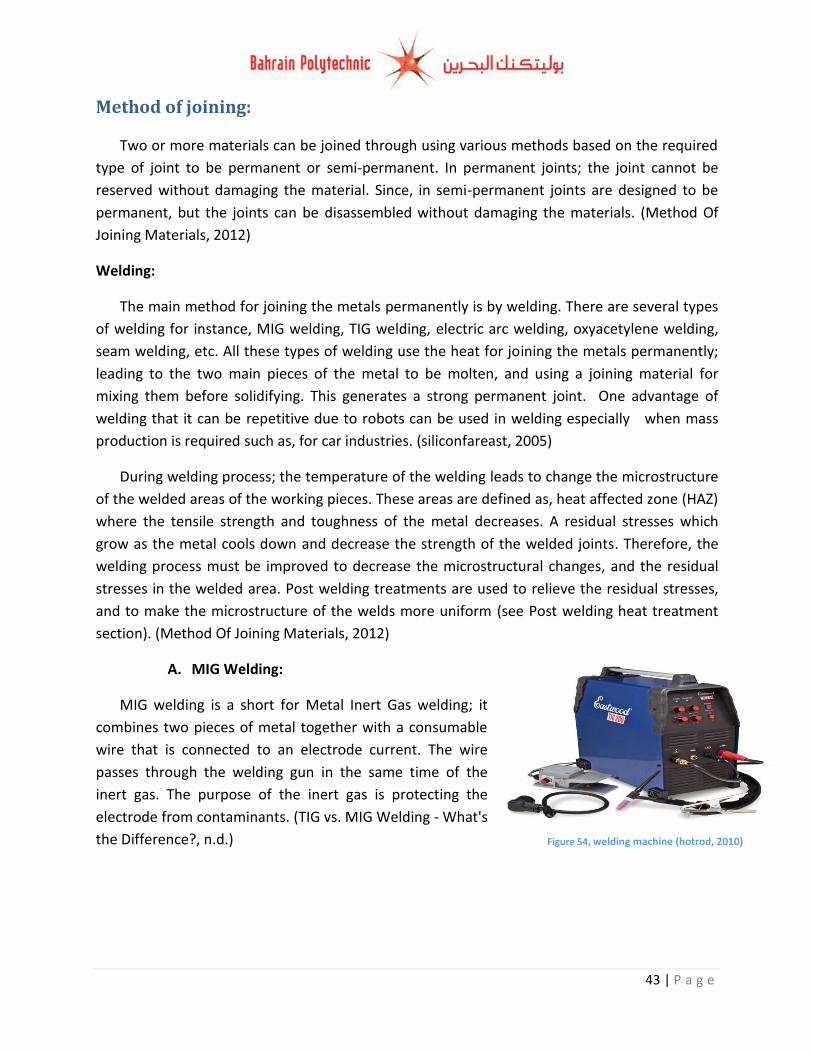
Figure 54, welding machine (hotrod, 2010)
Method of joining:
Two or more materials can be joined through using various methods based on the required
type of joint to be permanent or semi-permanent. In permanent joints; the joint cannot be
reserved without damaging the material. Since, in semi-permanent joints are designed to be
permanent, but the joints can be disassembled without damaging the materials. (Method Of
Joining Materials, 2012)
Welding:
The main method for joining the metals permanently is by welding. There are several types
of welding for instance, MIG welding, TIG welding, electric arc welding, oxyacetylene welding,
seam welding, etc. All these types of welding use the heat for joining the metals permanently;
leading to the two main pieces of the metal to be molten, and using a joining material for
mixing them before solidifying. This generates a strong permanent joint. One advantage of
welding that it can be repetitive due to robots can be used in welding especially when mass
production is required such as, for car industries. (siliconfareast, 2005)
During welding process; the temperature of the welding leads to change the microstructure
of the welded areas of the working pieces. These areas are defined as, heat affected zone (HAZ)
where the tensile strength and toughness of the metal decreases. A residual stresses which
grow as the metal cools down and decrease the strength of the welded joints. Therefore, the
welding process must be improved to decrease the microstructural changes, and the residual
stresses in the welded area. Post welding treatments are used to relieve the residual stresses,
and to make the microstructure of the welds more uniform (see Post welding heat treatment
section). (Method Of Joining Materials, 2012)
A. MIG Welding:
MIG welding is a short for Metal Inert Gas welding; it
combines two pieces of metal together with a consumable
wire that is connected to an electrode current. The wire
passes through the welding gun in the same time of the
inert gas. The purpose of the inert gas is protecting the
electrode from contaminants. (TIG vs. MIG Welding - What's
the Difference?, n.d.)
44 | P a g e
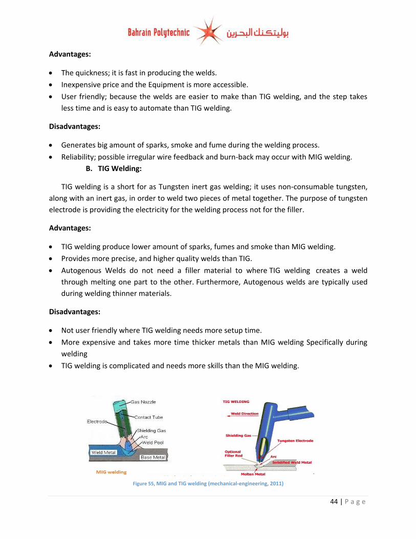
Figure 55, MIG and TIG welding (mechanical-engineering, 2011)
Advantages:
The quickness; it is fast in producing the welds.
Inexpensive price and the Equipment is more accessible.
User friendly; because the welds are easier to make than TIG welding, and the step takes
less time and is easy to automate than TIG welding.
Disadvantages:
Generates big amount of sparks, smoke and fume during the welding process.
Reliability; possible irregular wire feedback and burn-back may occur with MIG welding.
B. TIG Welding:
TIG welding is a short for as Tungsten inert gas welding; it uses non-consumable tungsten,
along with an inert gas, in order to weld two pieces of metal together. The purpose of tungsten
electrode is providing the electricity for the welding process not for the filler.
Advantages:
TIG welding produce lower amount of sparks, fumes and smoke than MIG welding.
Provides more precise, and higher quality welds than TIG.
Autogenous Welds do not need a filler material to where TIG welding creates a weld
through melting one part to the other. Furthermore, Autogenous welds are typically used
during welding thinner materials.
Disadvantages:
Not user friendly where TIG welding needs more setup time.
More expensive and takes more time thicker metals than MIG welding Specifically during
welding
TIG welding is complicated and needs more skills than the MIG welding.
45 | P a g e
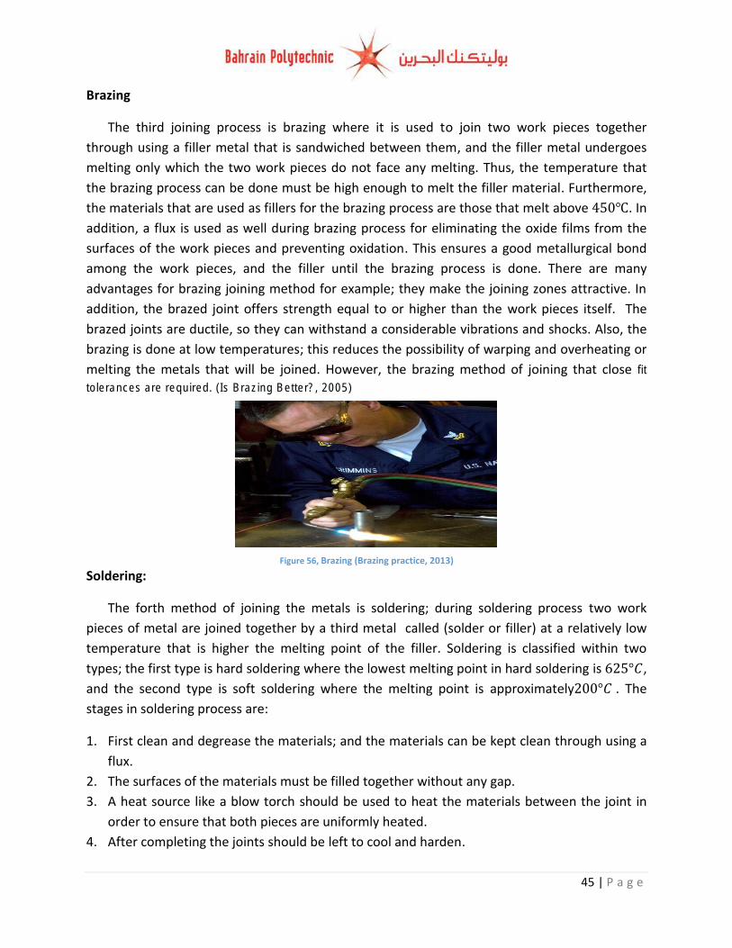
Figure 56, Brazing (Brazing practice, 2013)
Brazing
The third joining process is brazing where it is used to join two work pieces together
through using a filler metal that is sandwiched between them, and the filler metal undergoes
melting only which the two work pieces do not face any melting. Thus, the temperature that
the brazing process can be done must be high enough to melt the filler material. Furthermore,
the materials that are used as fillers for the brazing process are those that melt above . In
addition, a flux is used as well during brazing process for eliminating the oxide films from the
surfaces of the work pieces and preventing oxidation. This ensures a good metallurgical bond
among the work pieces, and the filler until the brazing process is done. There are many
advantages for brazing joining method for example; they make the joining zones attractive. In
addition, the brazed joint offers strength equal to or higher than the work pieces itself. The
brazed joints are ductile, so they can withstand a considerable vibrations and shocks. Also, the
brazing is done at low temperatures; this reduces the possibility of warping and overheating or
melting the metals that will be joined. However, the brazing method of joining that close fit
tolerances are required. (Is Brazing Better?, 2005)
Soldering:
The forth method of joining the metals is soldering; during soldering process two work
pieces of metal are joined together by a third metal called (solder or filler) at a relatively low
temperature that is higher the melting point of the filler. Soldering is classified within two
types; the first type is hard soldering where the lowest melting point in hard soldering is ,
and the second type is soft soldering where the melting point is approximately . The
stages in soldering process are:
1. First clean and degrease the materials; and the materials can be kept clean through using a
flux.
2. The surfaces of the materials must be filled together without any gap.
3. A heat source like a blow torch should be used to heat the materials between the joint in
order to ensure that both pieces are uniformly heated.
4. After completing the joints should be left to cool and harden.

46 | P a g e
Figure 57, Gas blow torch (directindustry, 2011)
Advantages:
Requires lower power.
Low joining temperature.
Dissimilar materials can be joined together.
There are no residual stresses in the joint parts.
User friendly; easily automated joining process.
Microstructure is not affected by heat of soldering.
Disadvantages:
Requires careful removal of the flux residuals to prevent corrosion.
Cannot be used for joining large sections.
Cannot be used for joining in high temperature applications. (tech, n.d.)
Selection of method of joining:
All of the previous mentioned methods are about permanent joining methods, however,
there is many other Simi-permanent method of joining such as using nuts and bolts for joining;
since the permanent joining method is stronger and we do not need to disassemble the chassis.
Therefore, I will choose a type of permanent joining method. The available permanent joining
method at building 30 is welding (MIG welding and TIG welding); thus I will make the
comparison between the two types only
Decision matrix (for choosing the type of welding that is available at building 30):
Factor Cost Safety User friendly
Total Mark: Mark: 7 Mark: 7 Mark: 10
Requirements Less in cost Safe welding method Easy to use
MIG welding 7*7 4*7 9*10 167
TIG welding 5*7 6*7 6*10 137 Table 4, decision matrix
Due to, the MIG welding is faster, easier where it do not requires skilled hand for doing it,
also, it is cheaper than TIG welding and the equipment is more accessible I will choose MIG
welding for welding the members of the chassis.
47 | P a g e
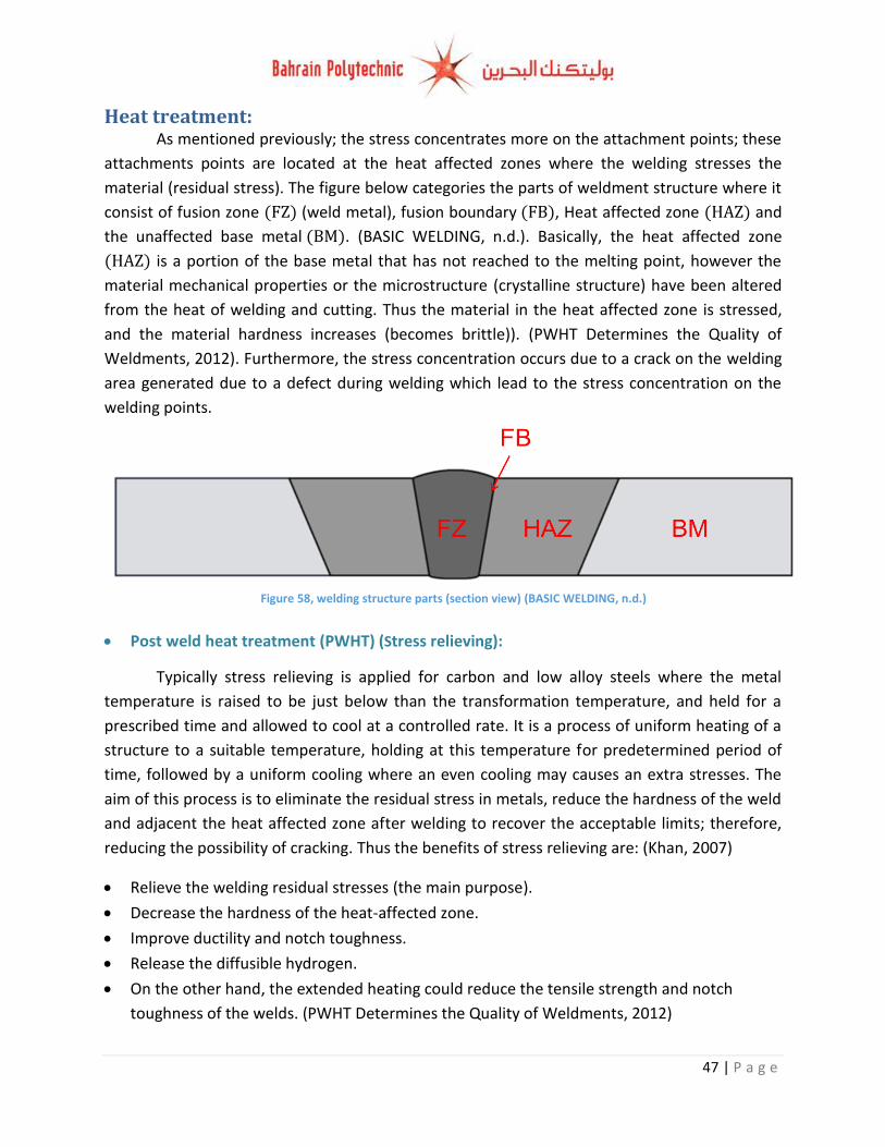
Figure 58, welding structure parts (section view) (BASIC WELDING, n.d.)
Heat treatment: As mentioned previously; the stress concentrates more on the attachment points; these
attachments points are located at the heat affected zones where the welding stresses the
material (residual stress). The figure below categories the parts of weldment structure where it
consist of fusion zone (weld metal), fusion boundary , Heat affected zone and
the unaffected base metal . (BASIC WELDING, n.d.). Basically, the heat affected zone
is a portion of the base metal that has not reached to the melting point, however the
material mechanical properties or the microstructure (crystalline structure) have been altered
from the heat of welding and cutting. Thus the material in the heat affected zone is stressed,
and the material hardness increases (becomes brittle)). (PWHT Determines the Quality of
Weldments, 2012). Furthermore, the stress concentration occurs due to a crack on the welding
area generated due to a defect during welding which lead to the stress concentration on the
welding points.
Post weld heat treatment (PWHT) (Stress relieving):
Typically stress relieving is applied for carbon and low alloy steels where the metal
temperature is raised to be just below than the transformation temperature, and held for a
prescribed time and allowed to cool at a controlled rate. It is a process of uniform heating of a
structure to a suitable temperature, holding at this temperature for predetermined period of
time, followed by a uniform cooling where an even cooling may causes an extra stresses. The
aim of this process is to eliminate the residual stress in metals, reduce the hardness of the weld
and adjacent the heat affected zone after welding to recover the acceptable limits; therefore,
reducing the possibility of cracking. Thus the benefits of stress relieving are: (Khan, 2007)
Relieve the welding residual stresses (the main purpose).
Decrease the hardness of the heat-affected zone.
Improve ductility and notch toughness.
Release the diffusible hydrogen.
On the other hand, the extended heating could reduce the tensile strength and notch
toughness of the welds. (PWHT Determines the Quality of Weldments, 2012)
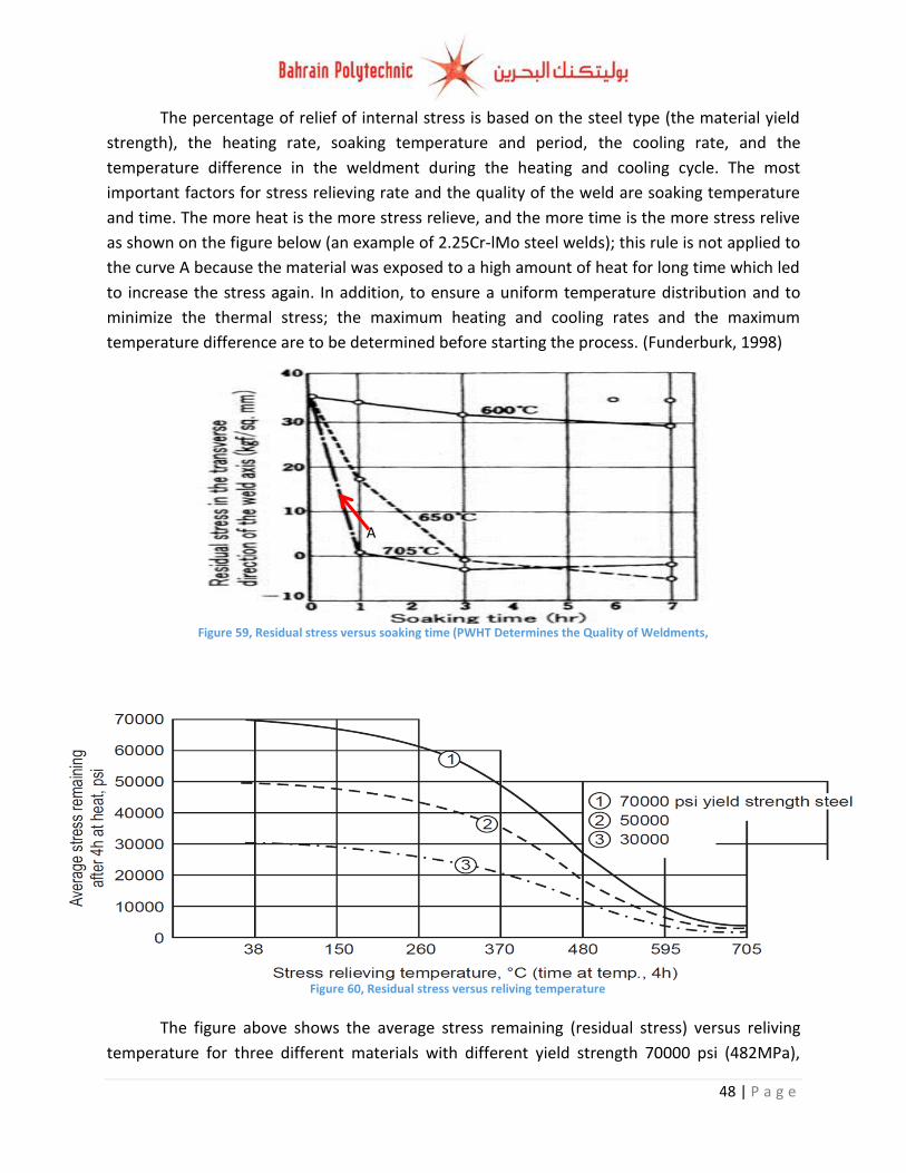
48 | P a g e
Figure 60, Residual stress versus reliving temperature
The percentage of relief of internal stress is based on the steel type (the material yield
strength), the heating rate, soaking temperature and period, the cooling rate, and the
temperature difference in the weldment during the heating and cooling cycle. The most
important factors for stress relieving rate and the quality of the weld are soaking temperature
and time. The more heat is the more stress relieve, and the more time is the more stress relive
as shown on the figure below (an example of 2.25Cr-lMo steel welds); this rule is not applied to
the curve A because the material was exposed to a high amount of heat for long time which led
to increase the stress again. In addition, to ensure a uniform temperature distribution and to
minimize the thermal stress; the maximum heating and cooling rates and the maximum
temperature difference are to be determined before starting the process. (Funderburk, 1998)
The figure above shows the average stress remaining (residual stress) versus reliving
temperature for three different materials with different yield strength 70000 psi (482MPa),
Figure 59, Residual stress versus soaking time (PWHT Determines the Quality of Weldments, 2012)
A
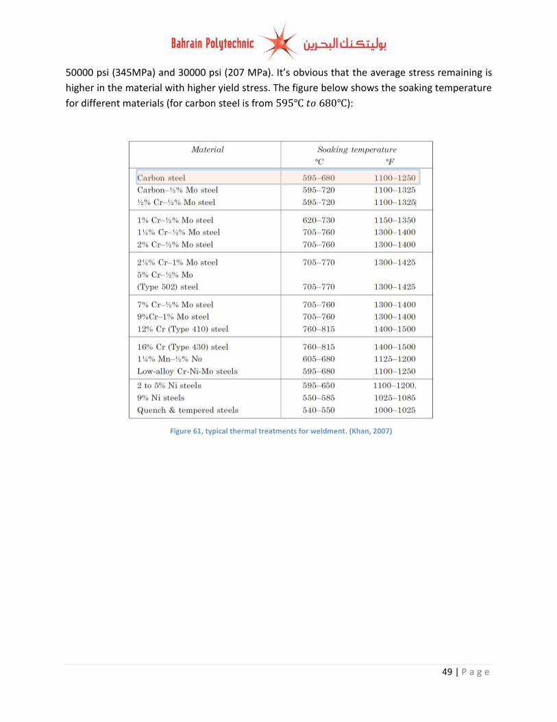
49 | P a g e
50000 psi (345MPa) and 30000 psi (207 MPa). It’s obvious that the average stress remaining is
higher in the material with higher yield stress. The figure below shows the soaking temperature
for different materials (for carbon steel is from ):
Figure 61, typical thermal treatments for weldment. (Khan, 2007)
50 | P a g e
Conclusion and future recommendations (optimization):
To conclude, the design of the chassis was successfully simulated and analysed through using
Finite element analysis feature in solid-works software. The minimum actual FOS during braking
is 1.89 (lower than the required which is 2), and the maximum amount of deflection is
0.643mm (lower than the maximum allowable deflection which is 1 mm), and the maximum
von Mises stress is 203.3MPa. The minimum actual FOS during acceleration is 2.89 (higher than
the required which is 2), and the maximum amount of deflection is 0.612mm (lower than the
maximum allowable deflection which is 1 mm), and the maximum von Mises stress is
121.6MPa. The minimum actual FOS during cornering is 1.6 (lower than the required which is
2), and the maximum amount of deflection is 0.682mm (lower than the maximum allowable
deflection which is 1 mm), and the maximum von Mises stress is 219.2MPa.
The difference between the values of FOS, stress and displacement happened as a result of
weight transfer which is longitudinal weight transfer during accelerating and braking, and
lateral weight transfer during cornering where the weight transfer adds more stresses on
different members based on the situation. For both acceleration and cornering situations the
FOS is higher than 2 expect some points (the FOS is lower than 2); this happened due to stress
concentration in the attachment points where they expose to higher stress from the attached
members, and they are heat effected zones where the heat of welding and cutting the material
stresses the material and causes residual stress.
For optimising the design it is recommended to heat treat the chassis In order to minimise
the stress concentration and the residual stress through using post weld heat treatment
method. It is recommended also adding light weight roll cage for decreasing the stress on the
chassis members, and taking into account selecting an appropriate member (a member that is
not expose to high value of stress) to mount the roll cage. Therefore, the roll cage will assist in
increasing the torsional rigidity of the chassis and helps the passenger from roll over and side
accidents.
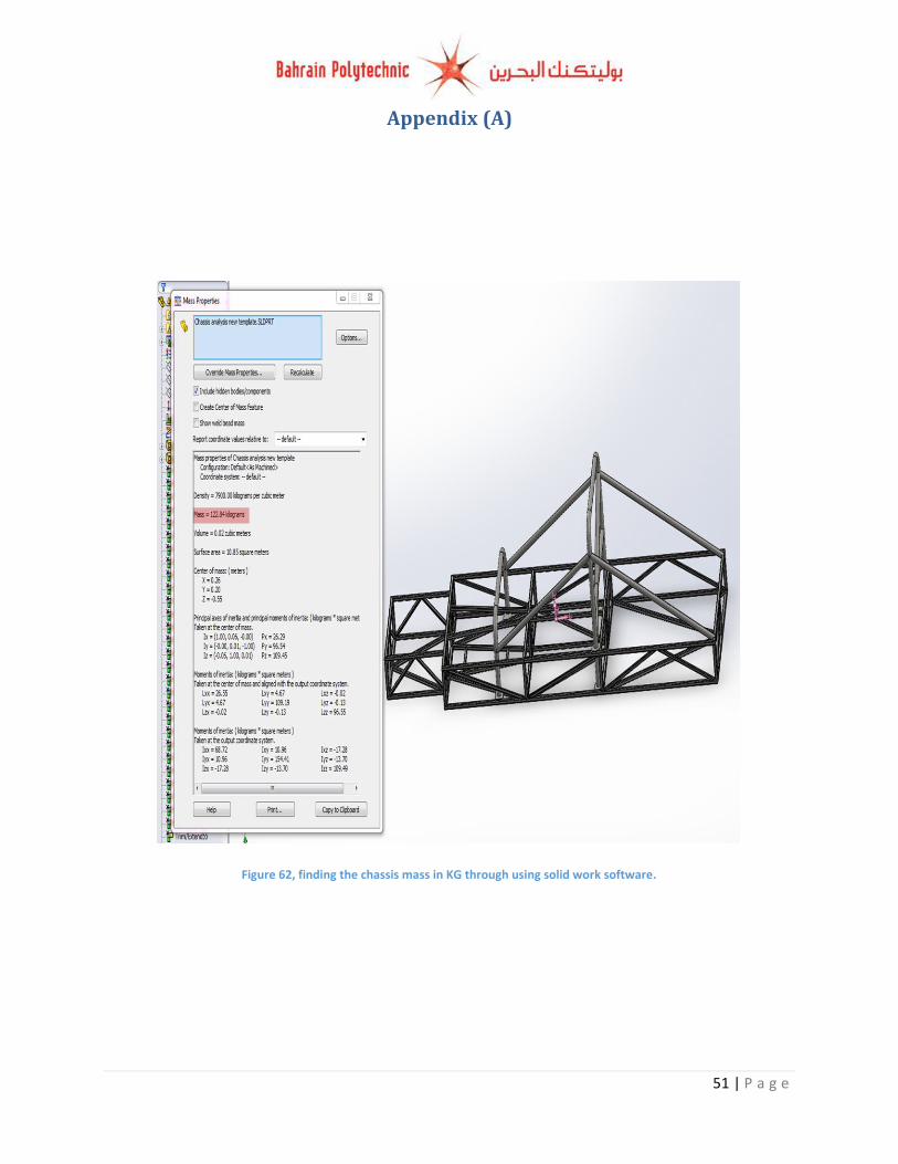
51 | P a g e
Appendix (A)
Figure 62, finding the chassis mass in KG through using solid work software.
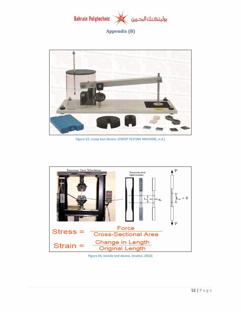
52 | P a g e
Appendix (B)
Figure 63, creep test device. (CREEP TESTING MACHINE, n.d.)
Figure 64, tensile test device. (matcsi, 2010)
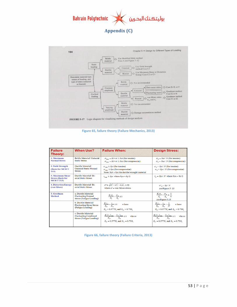
53 | P a g e
Appendix (C)
Figure 65, failure theory (Failure Mechanics, 2013)
Figure 66, failure theory (Failure Criteria, 2013)
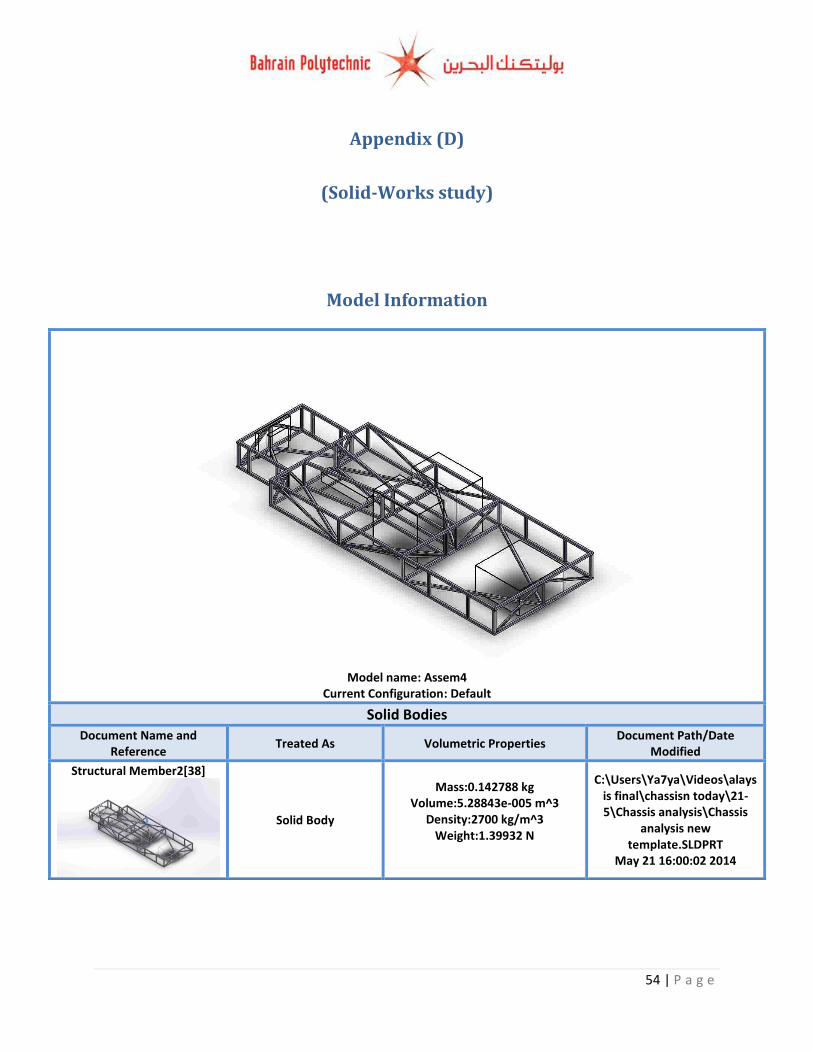
54 | P a g e
Appendix (D)
(Solid-Works study)
Model Information
Model name: Assem4
Current Configuration: Default
Solid Bodies
Document Name and Reference
Treated As Volumetric Properties Document Path/Date
Modified
Structural Member2[38]
Solid Body
Mass:0.142788 kg Volume:5.28843e-005 m^3
Density:2700 kg/m^3 Weight:1.39932 N
C:\Users\Ya7ya\Videos\alaysis final\chassisn today\21-5\Chassis analysis\Chassis
analysis new template.SLDPRT
May 21 16:00:02 2014
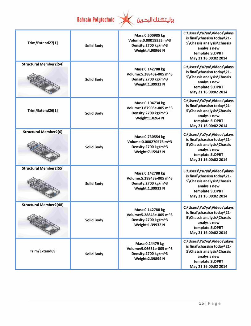
55 | P a g e
Trim/Extend27[1]
Solid Body
Mass:0.500985 kg Volume:0.00018555 m^3
Density:2700 kg/m^3 Weight:4.90966 N
C:\Users\Ya7ya\Videos\alaysis final\chassisn today\21-5\Chassis analysis\Chassis
analysis new template.SLDPRT
May 21 16:00:02 2014
Structural Member2[54]
Solid Body
Mass:0.142788 kg Volume:5.28843e-005 m^3
Density:2700 kg/m^3 Weight:1.39932 N
C:\Users\Ya7ya\Videos\alaysis final\chassisn today\21-5\Chassis analysis\Chassis
analysis new template.SLDPRT
May 21 16:00:02 2014
Trim/Extend26[1]
Solid Body
Mass:0.104734 kg Volume:3.87905e-005 m^3
Density:2700 kg/m^3 Weight:1.0264 N
C:\Users\Ya7ya\Videos\alaysis final\chassisn today\21-5\Chassis analysis\Chassis
analysis new template.SLDPRT
May 21 16:00:02 2014
Structural Member2[6]
Solid Body
Mass:0.730554 kg Volume:0.000270576 m^3
Density:2700 kg/m^3 Weight:7.15943 N
C:\Users\Ya7ya\Videos\alaysis final\chassisn today\21-5\Chassis analysis\Chassis
analysis new template.SLDPRT
May 21 16:00:02 2014
Structural Member2[55]
Solid Body
Mass:0.142788 kg Volume:5.28843e-005 m^3
Density:2700 kg/m^3 Weight:1.39932 N
C:\Users\Ya7ya\Videos\alaysis final\chassisn today\21-5\Chassis analysis\Chassis
analysis new template.SLDPRT
May 21 16:00:02 2014
Structural Member2[48]
Solid Body
Mass:0.142788 kg Volume:5.28843e-005 m^3
Density:2700 kg/m^3 Weight:1.39932 N
C:\Users\Ya7ya\Videos\alaysis final\chassisn today\21-5\Chassis analysis\Chassis
analysis new template.SLDPRT
May 21 16:00:02 2014
Trim/Extend69
Solid Body
Mass:0.24479 kg Volume:9.06631e-005 m^3
Density:2700 kg/m^3 Weight:2.39894 N
C:\Users\Ya7ya\Videos\alaysis final\chassisn today\21-5\Chassis analysis\Chassis
analysis new template.SLDPRT
May 21 16:00:02 2014
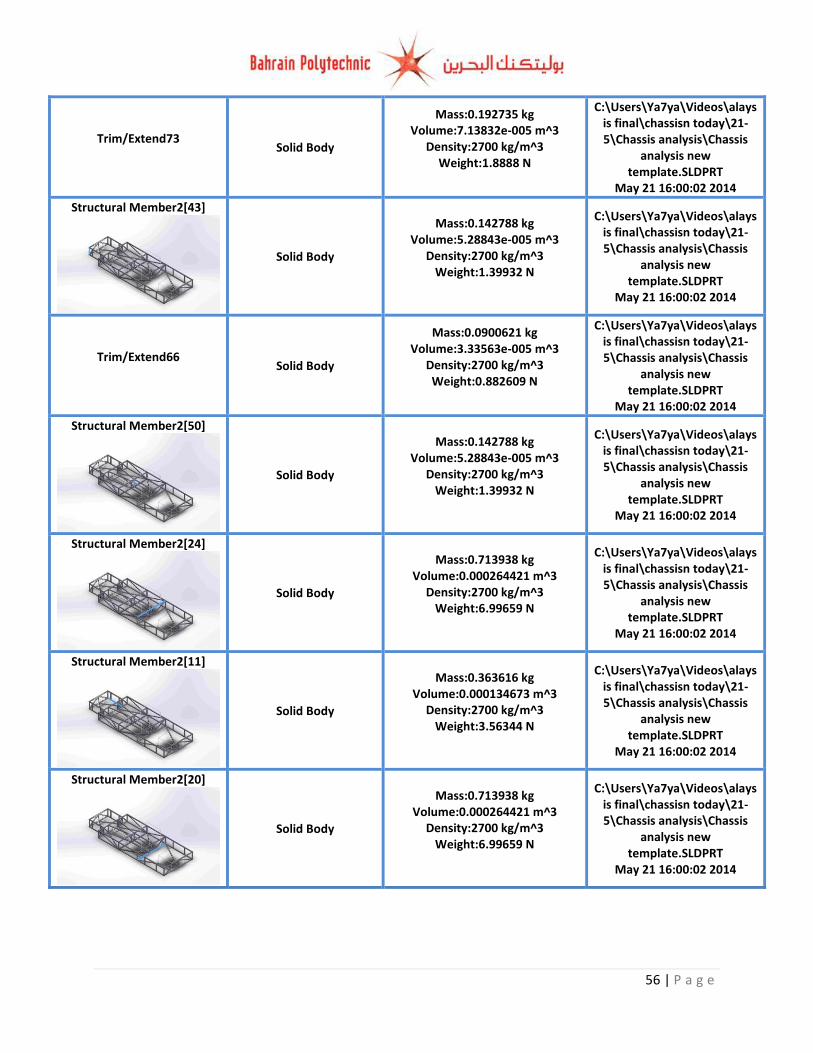
56 | P a g e
Trim/Extend73
Solid Body
Mass:0.192735 kg Volume:7.13832e-005 m^3
Density:2700 kg/m^3 Weight:1.8888 N
C:\Users\Ya7ya\Videos\alaysis final\chassisn today\21-5\Chassis analysis\Chassis
analysis new template.SLDPRT
May 21 16:00:02 2014
Structural Member2[43]
Solid Body
Mass:0.142788 kg Volume:5.28843e-005 m^3
Density:2700 kg/m^3 Weight:1.39932 N
C:\Users\Ya7ya\Videos\alaysis final\chassisn today\21-5\Chassis analysis\Chassis
analysis new template.SLDPRT
May 21 16:00:02 2014
Trim/Extend66
Solid Body
Mass:0.0900621 kg Volume:3.33563e-005 m^3
Density:2700 kg/m^3 Weight:0.882609 N
C:\Users\Ya7ya\Videos\alaysis final\chassisn today\21-5\Chassis analysis\Chassis
analysis new template.SLDPRT
May 21 16:00:02 2014
Structural Member2[50]
Solid Body
Mass:0.142788 kg Volume:5.28843e-005 m^3
Density:2700 kg/m^3 Weight:1.39932 N
C:\Users\Ya7ya\Videos\alaysis final\chassisn today\21-5\Chassis analysis\Chassis
analysis new template.SLDPRT
May 21 16:00:02 2014
Structural Member2[24]
Solid Body
Mass:0.713938 kg Volume:0.000264421 m^3
Density:2700 kg/m^3 Weight:6.99659 N
C:\Users\Ya7ya\Videos\alaysis final\chassisn today\21-5\Chassis analysis\Chassis
analysis new template.SLDPRT
May 21 16:00:02 2014
Structural Member2[11]
Solid Body
Mass:0.363616 kg Volume:0.000134673 m^3
Density:2700 kg/m^3 Weight:3.56344 N
C:\Users\Ya7ya\Videos\alaysis final\chassisn today\21-5\Chassis analysis\Chassis
analysis new template.SLDPRT
May 21 16:00:02 2014
Structural Member2[20]
Solid Body
Mass:0.713938 kg Volume:0.000264421 m^3
Density:2700 kg/m^3 Weight:6.99659 N
C:\Users\Ya7ya\Videos\alaysis final\chassisn today\21-5\Chassis analysis\Chassis
analysis new template.SLDPRT
May 21 16:00:02 2014
57 | P a g e
Structural Member2[71]
Solid Body
Mass:0.142788 kg Volume:5.28843e-005 m^3
Density:2700 kg/m^3 Weight:1.39932 N
C:\Users\Ya7ya\Videos\alaysis final\chassisn today\21-5\Chassis analysis\Chassis
analysis new template.SLDPRT
May 21 16:00:02 2014
Structural Member2[66]
Solid Body
Mass:0.142788 kg Volume:5.28843e-005 m^3
Density:2700 kg/m^3 Weight:1.39932 N
C:\Users\Ya7ya\Videos\alaysis final\chassisn today\21-5\Chassis analysis\Chassis
analysis new template.SLDPRT
May 21 16:00:02 2014
Trim/Extend83
Solid Body
Mass:0.500985 kg Volume:0.00018555 m^3
Density:2700 kg/m^3 Weight:4.90966 N
C:\Users\Ya7ya\Videos\alaysis final\chassisn today\21-5\Chassis analysis\Chassis
analysis new template.SLDPRT
May 21 16:00:02 2014
Trim/Extend64
Solid Body
Mass:0.0925187 kg Volume:3.42662e-005 m^3
Density:2700 kg/m^3 Weight:0.906683 N
C:\Users\Ya7ya\Videos\alaysis final\chassisn today\21-5\Chassis analysis\Chassis
analysis new template.SLDPRT
May 21 16:00:02 2014
Structural Member2[42]
Solid Body
Mass:0.142788 kg Volume:5.28843e-005 m^3
Density:2700 kg/m^3 Weight:1.39932 N
C:\Users\Ya7ya\Videos\alaysis final\chassisn today\21-5\Chassis analysis\Chassis
analysis new template.SLDPRT
May 21 16:00:02 2014
Trim/Extend98
Solid Body
Mass:0.26034 kg Volume:9.64223e-005 m^3
Density:2700 kg/m^3 Weight:2.55133 N
C:\Users\Ya7ya\Videos\alaysis final\chassisn today\21-5\Chassis analysis\Chassis
analysis new template.SLDPRT
May 21 16:00:02 2014
Trim/Extend109
Solid Body
Mass:0.250406 kg Volume:9.27429e-005 m^3
Density:2700 kg/m^3 Weight:2.45398 N
C:\Users\Ya7ya\Videos\alaysis final\chassisn today\21-5\Chassis analysis\Chassis
analysis new template.SLDPRT
May 21 16:00:02 2014
Trim/Extend80
Solid Body
Mass:0.54274 kg Volume:0.000201015 m^3
Density:2700 kg/m^3 Weight:5.31885 N
C:\Users\Ya7ya\Videos\alaysis final\chassisn today\21-5\Chassis analysis\Chassis
analysis new template.SLDPRT
May 21 16:00:02 2014
58 | P a g e
Trim/Extend23[1]
Solid Body
Mass:0.713938 kg Volume:0.000264421 m^3
Density:2700 kg/m^3 Weight:6.99659 N
C:\Users\Ya7ya\Videos\alaysis final\chassisn today\21-5\Chassis analysis\Chassis
analysis new template.SLDPRT
May 21 16:00:02 2014
Structural Member2[16]
Solid Body
Mass:0.51138 kg Volume:0.0001894 m^3
Density:2700 kg/m^3 Weight:5.01152 N
C:\Users\Ya7ya\Videos\alaysis final\chassisn today\21-5\Chassis analysis\Chassis
analysis new template.SLDPRT
May 21 16:00:02 2014
Structural Member2[7]
Solid Body
Mass:0.511387 kg Volume:0.000189403 m^3
Density:2700 kg/m^3 Weight:5.01159 N
C:\Users\Ya7ya\Videos\alaysis final\chassisn today\21-5\Chassis analysis\Chassis
analysis new template.SLDPRT
May 21 16:00:02 2014
Trim/Extend10[6]
Solid Body
Mass:0.142788 kg Volume:5.28843e-005 m^3
Density:2700 kg/m^3 Weight:1.39932 N
C:\Users\Ya7ya\Videos\alaysis final\chassisn today\21-5\Chassis analysis\Chassis
analysis new template.SLDPRT
May 21 16:00:02 2014
Structural Member2[36]
Solid Body
Mass:0.142788 kg Volume:5.28843e-005 m^3
Density:2700 kg/m^3 Weight:1.39932 N
C:\Users\Ya7ya\Videos\alaysis final\chassisn today\21-5\Chassis analysis\Chassis
analysis new template.SLDPRT
May 21 16:00:02 2014
Structural Member2[26]
Solid Body
Mass:0.363611 kg Volume:0.000134671 m^3
Density:2700 kg/m^3 Weight:3.56339 N
C:\Users\Ya7ya\Videos\alaysis final\chassisn today\21-5\Chassis analysis\Chassis
analysis new template.SLDPRT
May 21 16:00:02 2014
Structural Member2[33]
Solid Body
Mass:0.461558 kg Volume:0.000170948 m^3
Density:2700 kg/m^3 Weight:4.52327 N
C:\Users\Ya7ya\Videos\alaysis final\chassisn today\21-5\Chassis analysis\Chassis
analysis new template.SLDPRT
May 21 16:00:02 2014
59 | P a g e
Structural Member2[67]
Solid Body
Mass:0.142788 kg Volume:5.28843e-005 m^3
Density:2700 kg/m^3 Weight:1.39932 N
C:\Users\Ya7ya\Videos\alaysis final\chassisn today\21-5\Chassis analysis\Chassis
analysis new template.SLDPRT
May 21 16:00:02 2014
Structural Member2[72]
Solid Body
Mass:0.142788 kg Volume:5.28843e-005 m^3
Density:2700 kg/m^3 Weight:1.39932 N
C:\Users\Ya7ya\Videos\alaysis final\chassisn today\21-5\Chassis analysis\Chassis
analysis new template.SLDPRT
May 21 16:00:02 2014
Structural Member2[32]
Solid Body
Mass:0.461558 kg Volume:0.000170948 m^3
Density:2700 kg/m^3 Weight:4.52327 N
C:\Users\Ya7ya\Videos\alaysis final\chassisn today\21-5\Chassis analysis\Chassis
analysis new template.SLDPRT
May 21 16:00:02 2014
Trim/Extend110
Solid Body
Mass:0.250406 kg Volume:9.27429e-005 m^3
Density:2700 kg/m^3 Weight:2.45398 N
C:\Users\Ya7ya\Videos\alaysis final\chassisn today\21-5\Chassis analysis\Chassis
analysis new template.SLDPRT
May 21 16:00:02 2014
Trim/Extend86
Solid Body
Mass:0.411776 kg Volume:0.00015251 m^3
Density:2700 kg/m^3 Weight:4.03541 N
C:\Users\Ya7ya\Videos\alaysis final\chassisn today\21-5\Chassis analysis\Chassis
analysis new template.SLDPRT
May 21 16:00:02 2014
Trim/Extend10[8]
Solid Body
Mass:0.142788 kg Volume:5.28843e-005 m^3
Density:2700 kg/m^3 Weight:1.39932 N
C:\Users\Ya7ya\Videos\alaysis final\chassisn today\21-5\Chassis analysis\Chassis
analysis new template.SLDPRT
May 21 16:00:02 2014
Trim/Extend27[2]
Solid Body
Mass:0.500985 kg Volume:0.00018555 m^3
Density:2700 kg/m^3 Weight:4.90966 N
C:\Users\Ya7ya\Videos\alaysis final\chassisn today\21-5\Chassis analysis\Chassis
analysis new template.SLDPRT
May 21 16:00:02 2014
Trim/Extend85
Solid Body
Mass:0.535741 kg Volume:0.000198423 m^3
Density:2700 kg/m^3 Weight:5.25026 N
C:\Users\Ya7ya\Videos\alaysis final\chassisn today\21-5\Chassis analysis\Chassis
analysis new template.SLDPRT
May 21 16:00:02 2014
60 | P a g e
Structural Member2[25]
Solid Body
Mass:0.713921 kg Volume:0.000264415 m^3
Density:2700 kg/m^3 Weight:6.99643 N
C:\Users\Ya7ya\Videos\alaysis final\chassisn today\21-5\Chassis analysis\Chassis
analysis new template.SLDPRT
May 21 16:00:02 2014
Trim/Extend88
Solid Body
Mass:0.749248 kg Volume:0.000277499 m^3
Density:2700 kg/m^3 Weight:7.34263 N
C:\Users\Ya7ya\Videos\alaysis final\chassisn today\21-5\Chassis analysis\Chassis
analysis new template.SLDPRT
May 21 16:00:02 2014
Trim/Extend10[1]
Solid Body
Mass:0.142788 kg Volume:5.28843e-005 m^3
Density:2700 kg/m^3 Weight:1.39932 N
C:\Users\Ya7ya\Videos\alaysis final\chassisn today\21-5\Chassis analysis\Chassis
analysis new template.SLDPRT
May 21 16:00:02 2014
Trim/Extend67
Solid Body
Mass:0.0925187 kg Volume:3.42662e-005 m^3
Density:2700 kg/m^3 Weight:0.906683 N
C:\Users\Ya7ya\Videos\alaysis final\chassisn today\21-5\Chassis analysis\Chassis
analysis new template.SLDPRT
May 21 16:00:02 2014
Structural Member2[12]
Solid Body
Mass:0.692355 kg Volume:0.000256428 m^3
Density:2700 kg/m^3 Weight:6.78508 N
C:\Users\Ya7ya\Videos\alaysis final\chassisn today\21-5\Chassis analysis\Chassis
analysis new template.SLDPRT
May 21 16:00:02 2014
Structural Member2[9]
Solid Body
Mass:0.363611 kg Volume:0.000134671 m^3
Density:2700 kg/m^3 Weight:3.56339 N
C:\Users\Ya7ya\Videos\alaysis final\chassisn today\21-5\Chassis analysis\Chassis
analysis new template.SLDPRT
May 21 16:00:02 2014
Structural Member2[46]
Solid Body
Mass:0.142788 kg Volume:5.28843e-005 m^3
Density:2700 kg/m^3 Weight:1.39932 N
C:\Users\Ya7ya\Videos\alaysis final\chassisn today\21-5\Chassis analysis\Chassis
analysis new template.SLDPRT
May 21 16:00:02 2014
61 | P a g e
Structural Member2[28]
Solid Body
Mass:0.363616 kg Volume:0.000134673 m^3
Density:2700 kg/m^3 Weight:3.56344 N
C:\Users\Ya7ya\Videos\alaysis final\chassisn today\21-5\Chassis analysis\Chassis
analysis new template.SLDPRT
May 21 16:00:02 2014
Structural Member2[1]
Solid Body
Mass:0.692355 kg Volume:0.000256428 m^3
Density:2700 kg/m^3 Weight:6.78508 N
C:\Users\Ya7ya\Videos\alaysis final\chassisn today\21-5\Chassis analysis\Chassis
analysis new template.SLDPRT
May 21 16:00:02 2014
Structural Member2[68]
Solid Body
Mass:0.142788 kg Volume:5.28843e-005 m^3
Density:2700 kg/m^3 Weight:1.39932 N
C:\Users\Ya7ya\Videos\alaysis final\chassisn today\21-5\Chassis analysis\Chassis
analysis new template.SLDPRT
May 21 16:00:02 2014
Trim/Extend89
Solid Body
Mass:0.175529 kg Volume:6.50108e-005 m^3
Density:2700 kg/m^3 Weight:1.72019 N
C:\Users\Ya7ya\Videos\alaysis final\chassisn today\21-5\Chassis analysis\Chassis
analysis new template.SLDPRT
May 21 16:00:02 2014
Structural Member2[17]
Solid Body
Mass:0.730554 kg Volume:0.000270576 m^3
Density:2700 kg/m^3 Weight:7.15943 N
C:\Users\Ya7ya\Videos\alaysis final\chassisn today\21-5\Chassis analysis\Chassis
analysis new template.SLDPRT
May 21 16:00:02 2014
Trim/Extend82
Solid Body
Mass:0.528305 kg Volume:0.000195668 m^3
Density:2700 kg/m^3 Weight:5.17738 N
C:\Users\Ya7ya\Videos\alaysis final\chassisn today\21-5\Chassis analysis\Chassis
analysis new template.SLDPRT
May 21 16:00:02 2014
Trim/Extend97
Solid Body
Mass:0.260342 kg Volume:9.64231e-005 m^3
Density:2700 kg/m^3 Weight:2.55135 N
C:\Users\Ya7ya\Videos\alaysis final\chassisn today\21-5\Chassis analysis\Chassis
analysis new template.SLDPRT
May 21 16:00:02 2014
62 | P a g e
Structural Member2[37]
Solid Body
Mass:0.142788 kg Volume:5.28843e-005 m^3
Density:2700 kg/m^3 Weight:1.39932 N
C:\Users\Ya7ya\Videos\alaysis final\chassisn today\21-5\Chassis analysis\Chassis
analysis new template.SLDPRT
May 21 16:00:02 2014
Structural Member2[47]
Solid Body
Mass:0.142788 kg Volume:5.28843e-005 m^3
Density:2700 kg/m^3 Weight:1.39932 N
C:\Users\Ya7ya\Videos\alaysis final\chassisn today\21-5\Chassis analysis\Chassis
analysis new template.SLDPRT
May 21 16:00:02 2014
Trim/Extend10[3]
Solid Body
Mass:0.142788 kg Volume:5.28843e-005 m^3
Density:2700 kg/m^3 Weight:1.39932 N
C:\Users\Ya7ya\Videos\alaysis final\chassisn today\21-5\Chassis analysis\Chassis
analysis new template.SLDPRT
May 21 16:00:02 2014
Structural Member2[45]
Solid Body
Mass:0.142788 kg Volume:5.28843e-005 m^3
Density:2700 kg/m^3 Weight:1.39932 N
C:\Users\Ya7ya\Videos\alaysis final\chassisn today\21-5\Chassis analysis\Chassis
analysis new template.SLDPRT
May 21 16:00:02 2014
Trim/Extend10[10]
Solid Body
Mass:0.142788 kg Volume:5.28843e-005 m^3
Density:2700 kg/m^3 Weight:1.39932 N
C:\Users\Ya7ya\Videos\alaysis final\chassisn today\21-5\Chassis analysis\Chassis
analysis new template.SLDPRT
May 21 16:00:02 2014
Trim/Extend26[2]
Solid Body
Mass:0.0587917 kg Volume:2.17747e-005 m^3
Density:2700 kg/m^3 Weight:0.576158 N
C:\Users\Ya7ya\Videos\alaysis final\chassisn today\21-5\Chassis analysis\Chassis
analysis new template.SLDPRT
May 21 16:00:02 2014
Trim/Extend65
Solid Body
Mass:0.0902453 kg Volume:3.34242e-005 m^3
Density:2700 kg/m^3 Weight:0.884404 N
C:\Users\Ya7ya\Videos\alaysis final\chassisn today\21-5\Chassis analysis\Chassis
analysis new template.SLDPRT
May 21 16:00:02 2014
Trim/Extend76
Solid Body
Mass:0.244756 kg Volume:9.06504e-005 m^3
Density:2700 kg/m^3 Weight:2.39861 N
C:\Users\Ya7ya\Videos\alaysis final\chassisn today\21-5\Chassis analysis\Chassis
analysis new template.SLDPRT
May 21 16:00:02 2014
63 | P a g e
Trim/Extend72
Solid Body
Mass:0.192735 kg Volume:7.13832e-005 m^3
Density:2700 kg/m^3 Weight:1.8888 N
C:\Users\Ya7ya\Videos\alaysis final\chassisn today\21-5\Chassis analysis\Chassis
analysis new template.SLDPRT
May 21 16:00:02 2014
Structural Member2[2]
Solid Body
Mass:0.730554 kg Volume:0.000270576 m^3
Density:2700 kg/m^3 Weight:7.15943 N
C:\Users\Ya7ya\Videos\alaysis final\chassisn today\21-5\Chassis analysis\Chassis
analysis new template.SLDPRT
May 21 16:00:02 2014
Trim/Extend21[2]
Solid Body
Mass:0.461569 kg Volume:0.000170952 m^3
Density:2700 kg/m^3 Weight:4.52338 N
C:\Users\Ya7ya\Videos\alaysis final\chassisn today\21-5\Chassis analysis\Chassis
analysis new template.SLDPRT
May 21 16:00:02 2014
Trim/Extend10[5]
Solid Body
Mass:0.142788 kg Volume:5.28843e-005 m^3
Density:2700 kg/m^3 Weight:1.39932 N
C:\Users\Ya7ya\Videos\alaysis final\chassisn today\21-5\Chassis analysis\Chassis
analysis new template.SLDPRT
May 21 16:00:02 2014
Structural Member2[5]
Solid Body
Mass:0.51138 kg Volume:0.0001894 m^3
Density:2700 kg/m^3 Weight:5.01152 N
C:\Users\Ya7ya\Videos\alaysis final\chassisn today\21-5\Chassis analysis\Chassis
analysis new template.SLDPRT
May 21 16:00:02 2014
Structural Member2[69]
Solid Body
Mass:0.142788 kg Volume:5.28843e-005 m^3
Density:2700 kg/m^3 Weight:1.39932 N
C:\Users\Ya7ya\Videos\alaysis final\chassisn today\21-5\Chassis analysis\Chassis
analysis new template.SLDPRT
May 21 16:00:02 2014
Structural Member2[41]
Solid Body
Mass:0.142788 kg Volume:5.28843e-005 m^3
Density:2700 kg/m^3 Weight:1.39932 N
C:\Users\Ya7ya\Videos\alaysis final\chassisn today\21-5\Chassis analysis\Chassis
analysis new template.SLDPRT
May 21 16:00:02 2014
64 | P a g e
Trim/Extend24[4]
Solid Body
Mass:0.713938 kg Volume:0.000264421 m^3
Density:2700 kg/m^3 Weight:6.99659 N
C:\Users\Ya7ya\Videos\alaysis final\chassisn today\21-5\Chassis analysis\Chassis
analysis new template.SLDPRT
May 21 16:00:02 2014
Structural Member2[3]
Solid Body
Mass:0.692365 kg Volume:0.000256431 m^3
Density:2700 kg/m^3 Weight:6.78518 N
C:\Users\Ya7ya\Videos\alaysis final\chassisn today\21-5\Chassis analysis\Chassis
analysis new template.SLDPRT
May 21 16:00:02 2014
Structural Member2[15]
Solid Body
Mass:0.478172 kg Volume:0.000177101 m^3
Density:2700 kg/m^3 Weight:4.68609 N
C:\Users\Ya7ya\Videos\alaysis final\chassisn today\21-5\Chassis analysis\Chassis
analysis new template.SLDPRT
May 21 16:00:02 2014
Structural Member2[13]
Solid Body
Mass:0.730554 kg Volume:0.000270576 m^3
Density:2700 kg/m^3 Weight:7.15943 N
C:\Users\Ya7ya\Videos\alaysis final\chassisn today\21-5\Chassis analysis\Chassis
analysis new template.SLDPRT
May 21 16:00:02 2014
Structural Member2[18]
Solid Body
Mass:0.511387 kg Volume:0.000189403 m^3
Density:2700 kg/m^3 Weight:5.01159 N
C:\Users\Ya7ya\Videos\alaysis final\chassisn today\21-5\Chassis analysis\Chassis
analysis new template.SLDPRT
May 21 16:00:02 2014
Trim/Extend25[2]
Solid Body
Mass:0.713928 kg Volume:0.000264418 m^3
Density:2700 kg/m^3 Weight:6.99649 N
C:\Users\Ya7ya\Videos\alaysis final\chassisn today\21-5\Chassis analysis\Chassis
analysis new template.SLDPRT
May 21 16:00:02 2014
Trim/Extend90
Solid Body
Mass:0.175528 kg Volume:6.50105e-005 m^3
Density:2700 kg/m^3 Weight:1.72018 N
C:\Users\Ya7ya\Videos\alaysis final\chassisn today\21-5\Chassis analysis\Chassis
analysis new template.SLDPRT
May 21 16:00:02 2014
65 | P a g e
Structural Member2[27]
Solid Body
Mass:0.478181 kg Volume:0.000177104 m^3
Density:2700 kg/m^3 Weight:4.68617 N
C:\Users\Ya7ya\Videos\alaysis final\chassisn today\21-5\Chassis analysis\Chassis
analysis new template.SLDPRT
May 21 16:00:02 2014
Trim/Extend21[3]
Solid Body
Mass:0.461569 kg Volume:0.000170952 m^3
Density:2700 kg/m^3 Weight:4.52338 N
C:\Users\Ya7ya\Videos\alaysis final\chassisn today\21-5\Chassis analysis\Chassis
analysis new template.SLDPRT
May 21 16:00:02 2014
Trim/Extend87
Solid Body
Mass:0.41178 kg Volume:0.000152511 m^3
Density:2700 kg/m^3 Weight:4.03544 N
C:\Users\Ya7ya\Videos\alaysis final\chassisn today\21-5\Chassis analysis\Chassis
analysis new template.SLDPRT
May 21 16:00:02 2014
Structural Member2[4]
Solid Body
Mass:0.478172 kg Volume:0.000177101 m^3
Density:2700 kg/m^3 Weight:4.68609 N
C:\Users\Ya7ya\Videos\alaysis final\chassisn today\21-5\Chassis analysis\Chassis
analysis new template.SLDPRT
May 21 16:00:02 2014
Structural Member2[10]
Solid Body
Mass:0.478181 kg Volume:0.000177104 m^3
Density:2700 kg/m^3 Weight:4.68617 N
C:\Users\Ya7ya\Videos\alaysis final\chassisn today\21-5\Chassis analysis\Chassis
analysis new template.SLDPRT
May 21 16:00:02 2014
Trim/Extend79
Solid Body
Mass:0.752804 kg Volume:0.000278816 m^3
Density:2700 kg/m^3 Weight:7.37748 N
C:\Users\Ya7ya\Videos\alaysis final\chassisn today\21-5\Chassis analysis\Chassis
analysis new template.SLDPRT
May 21 16:00:02 2014
Trim/Extend84
Solid Body
Mass:0.494467 kg Volume:0.000183136 m^3
Density:2700 kg/m^3 Weight:4.84578 N
C:\Users\Ya7ya\Videos\alaysis final\chassisn today\21-5\Chassis analysis\Chassis
analysis new template.SLDPRT
May 21 16:00:02 2014
66 | P a g e
Structural Member2[14]
Solid Body
Mass:0.692365 kg Volume:0.000256431 m^3
Density:2700 kg/m^3 Weight:6.78518 N
C:\Users\Ya7ya\Videos\alaysis final\chassisn today\21-5\Chassis analysis\Chassis
analysis new template.SLDPRT
May 21 16:00:02 2014
Structural Member2[19]
Solid Body
Mass:0.478172 kg Volume:0.000177101 m^3
Density:2700 kg/m^3 Weight:4.68609 N
C:\Users\Ya7ya\Videos\alaysis final\chassisn today\21-5\Chassis analysis\Chassis
analysis new template.SLDPRT
May 21 16:00:02 2014
Structural Member2[49]
Solid Body
Mass:0.142788 kg Volume:5.28843e-005 m^3
Density:2700 kg/m^3 Weight:1.39932 N
C:\Users\Ya7ya\Videos\alaysis final\chassisn today\21-5\Chassis analysis\Chassis
analysis new template.SLDPRT
May 21 16:00:02 2014
Structural Member2[8]
Solid Body
Mass:0.478172 kg Volume:0.000177101 m^3
Density:2700 kg/m^3 Weight:4.68609 N
C:\Users\Ya7ya\Videos\alaysis final\chassisn today\21-5\Chassis analysis\Chassis
analysis new template.SLDPRT
May 21 16:00:02 2014
Trim/Extend81
Solid Body
Mass:0.542741 kg Volume:0.000201015 m^3
Density:2700 kg/m^3 Weight:5.31886 N
C:\Users\Ya7ya\Videos\alaysis final\chassisn today\21-5\Chassis analysis\Chassis
analysis new template.SLDPRT
May 21 16:00:02 2014
Structural Member2[65]
Solid Body
Mass:0.142788 kg Volume:5.28843e-005 m^3
Density:2700 kg/m^3 Weight:1.39932 N
C:\Users\Ya7ya\Videos\alaysis final\chassisn today\21-5\Chassis analysis\Chassis
analysis new template.SLDPRT
May 21 16:00:02 2014
Structural Member2[70]
Solid Body
Mass:0.142788 kg Volume:5.28843e-005 m^3
Density:2700 kg/m^3 Weight:1.39932 N
C:\Users\Ya7ya\Videos\alaysis final\chassisn today\21-5\Chassis analysis\Chassis
analysis new template.SLDPRT
May 21 16:00:02 2014
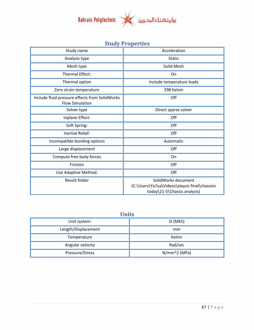
67 | P a g e
Study Properties Study name Acceleration
Analysis type Static
Mesh type Solid Mesh
Thermal Effect: On
Thermal option Include temperature loads
Zero strain temperature 298 Kelvin
Include fluid pressure effects from SolidWorks Flow Simulation
Off
Solver type Direct sparse solver
Inplane Effect: Off
Soft Spring: Off
Inertial Relief: Off
Incompatible bonding options Automatic
Large displacement Off
Compute free body forces On
Friction Off
Use Adaptive Method: Off
Result folder SolidWorks document (C:\Users\Ya7ya\Videos\alaysis final\chassisn
today\21-5\Chassis analysis)
Units Unit system: SI (MKS)
Length/Displacement mm
Temperature Kelvin
Angular velocity Rad/sec
Pressure/Stress N/mm^2 (MPa)
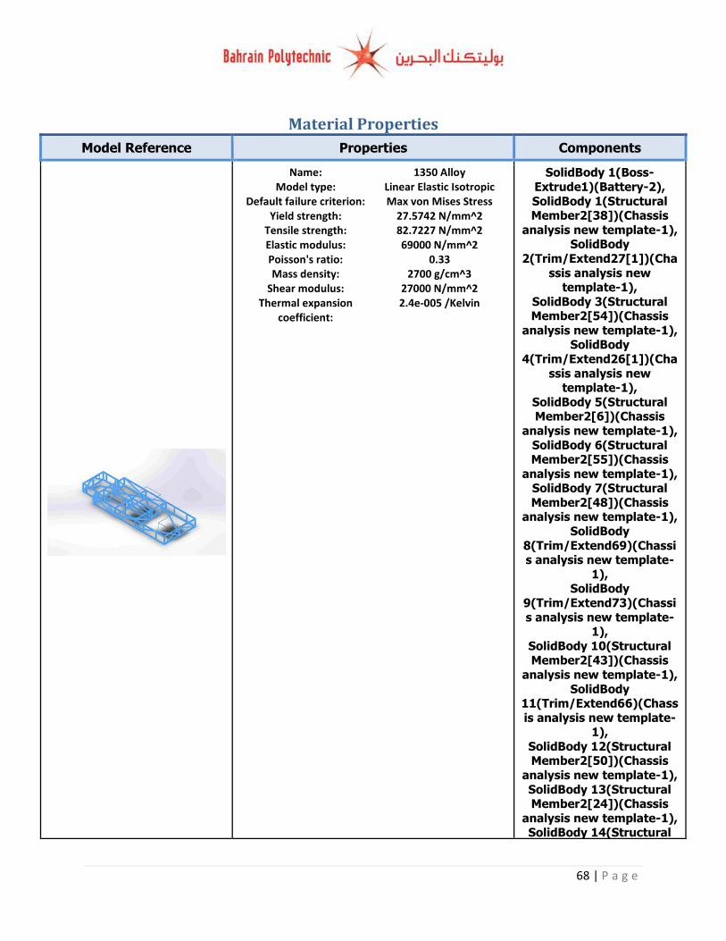
68 | P a g e
Material Properties
Model Reference Properties Components
Name: 1350 Alloy Model type: Linear Elastic Isotropic
Default failure criterion: Max von Mises Stress Yield strength: 27.5742 N/mm^2
Tensile strength: 82.7227 N/mm^2 Elastic modulus: 69000 N/mm^2 Poisson's ratio: 0.33 Mass density: 2700 g/cm^3
Shear modulus: 27000 N/mm^2 Thermal expansion
coefficient: 2.4e-005 /Kelvin
SolidBody 1(Boss-
Extrude1)(Battery-2),
SolidBody 1(Structural Member2[38])(Chassis
analysis new template-1), SolidBody
2(Trim/Extend27[1])(Cha
ssis analysis new template-1),
SolidBody 3(Structural Member2[54])(Chassis
analysis new template-1), SolidBody
4(Trim/Extend26[1])(Cha
ssis analysis new template-1),
SolidBody 5(Structural Member2[6])(Chassis
analysis new template-1),
SolidBody 6(Structural Member2[55])(Chassis
analysis new template-1), SolidBody 7(Structural
Member2[48])(Chassis analysis new template-1),
SolidBody
8(Trim/Extend69)(Chassis analysis new template-
1), SolidBody
9(Trim/Extend73)(Chassi
s analysis new template-1),
SolidBody 10(Structural Member2[43])(Chassis
analysis new template-1),
SolidBody 11(Trim/Extend66)(Chass
is analysis new template-1),
SolidBody 12(Structural Member2[50])(Chassis
analysis new template-1),
SolidBody 13(Structural Member2[24])(Chassis
analysis new template-1), SolidBody 14(Structural
69 | P a g e
Member2[11])(Chassis
analysis new template-1), SolidBody 15(Structural
Member2[20])(Chassis analysis new template-1),
SolidBody 16(Structural Member2[71])(Chassis
analysis new template-1),
SolidBody 17(Structural Member2[66])(Chassis
analysis new template-1), SolidBody
18(Trim/Extend83)(Chass
is analysis new template-1),
SolidBody 19(Trim/Extend64)(Chass
is analysis new template-1),
SolidBody 20(Structural
Member2[42])(Chassis analysis new template-1),
SolidBody 21(Trim/Extend98)(Chass
is analysis new template-
1), SolidBody
22(Trim/Extend109)(Chassis analysis new
template-1), SolidBody
23(Trim/Extend80)(Chass
is analysis new template-1),
SolidBody 24(Trim/Extend23[1])(Ch
assis analysis new
template-1), SolidBody 25(Structural
Member2[16])(Chassis analysis new template-1),
SolidBody 26(Structural
Member2[7])(Chassis analysis new template-1),
SolidBody 27(Trim/Extend10[6])(Ch
assis analysis new template-1),
SolidBody 28(Structural
Member2[36])(Chassis analysis new template-1),
SolidBody 29(Structural
70 | P a g e
Member2[26])(Chassis
analysis new template-1), SolidBody 30(Structural
Member2[33])(Chassis analysis new template-1),
SolidBody 31(Structural Member2[67])(Chassis
analysis new template-1),
SolidBody 32(Structural Member2[72])(Chassis
analysis new template-1), SolidBody 33(Structural
Member2[32])(Chassis
analysis new template-1), SolidBody
34(Trim/Extend110)(Chassis analysis new
template-1), SolidBody
35(Trim/Extend86)(Chass
is analysis new template-1),
SolidBody 36(Trim/Extend10[8])(Ch
assis analysis new
template-1), SolidBody
37(Trim/Extend27[2])(Chassis analysis new
template-1), SolidBody
38(Trim/Extend85)(Chass
is analysis new template-1),
SolidBody 39(Structural Member2[25])(Chassis
analysis new template-1),
SolidBody 40(Trim/Extend88)(Chass
is analysis new template-1),
SolidBody
41(Trim/Extend10[1])(Chassis analysis new
template-1), SolidBody
42(Trim/Extend67)(Chassis analysis new template-
1),
SolidBody 43(Structural Member2[12])(Chassis
analysis new template-1),
71 | P a g e
SolidBody 44(Structural
Member2[9])(Chassis analysis new template-1),
SolidBody 45(Structural Member2[46])(Chassis
analysis new template-1), SolidBody 46(Structural
Member2[28])(Chassis
analysis new template-1), SolidBody 47(Structural
Member2[1])(Chassis analysis new template-1),
SolidBody 48(Structural
Member2[68])(Chassis analysis new template-1),
SolidBody 49(Trim/Extend89)(Chass
is analysis new template-1),
SolidBody 50(Structural
Member2[17])(Chassis analysis new template-1),
SolidBody 51(Trim/Extend82)(Chass
is analysis new template-
1), SolidBody
52(Trim/Extend97)(Chassis analysis new template-
1), SolidBody 53(Structural
Member2[37])(Chassis
analysis new template-1), SolidBody 54(Structural
Member2[47])(Chassis analysis new template-1),
SolidBody
55(Trim/Extend10[3])(Chassis analysis new
template-1), SolidBody 56(Structural
Member2[45])(Chassis
analysis new template-1), SolidBody
57(Trim/Extend10[10])(Chassis analysis new
template-1), SolidBody
58(Trim/Extend26[2])(Ch
assis analysis new template-1),
SolidBody
72 | P a g e
59(Trim/Extend65)(Chass
is analysis new template-1),
SolidBody 60(Trim/Extend76)(Chass
is analysis new template-1),
SolidBody
61(Trim/Extend72)(Chassis analysis new template-
1), SolidBody 62(Structural
Member2[2])(Chassis
analysis new template-1), SolidBody
63(Trim/Extend21[2])(Chassis analysis new
template-1), SolidBody
64(Trim/Extend10[5])(Ch
assis analysis new template-1),
SolidBody 65(Structural Member2[5])(Chassis
analysis new template-1),
SolidBody 66(Structural Member2[69])(Chassis
analysis new template-1), SolidBody 67(Structural
Member2[41])(Chassis analysis new template-1),
SolidBody
68(Trim/Extend24[4])(Chassis analysis new
template-1), SolidBody 69(Structural
Member2[3])(Chassis
analysis new template-1), SolidBody 70(Structural
Member2[15])(Chassis analysis new template-1),
SolidBody 71(Structural
Member2[13])(Chassis analysis new template-1),
SolidBody 72(Structural Member2[18])(Chassis
analysis new template-1), SolidBody
73(Trim/Extend25[2])(Ch
assis analysis new template-1),
SolidBody
73 | P a g e
74(Trim/Extend90)(Chass
is analysis new template-1),
SolidBody 75(Structural Member2[27])(Chassis
analysis new template-1), SolidBody
76(Trim/Extend21[3])(Ch
assis analysis new template-1),
SolidBody 77(Trim/Extend87)(Chass
is analysis new template-
1), SolidBody 78(Structural
Member2[4])(Chassis analysis new template-1),
SolidBody 79(Structural Member2[10])(Chassis
analysis new template-1),
SolidBody 80(Trim/Extend79)(Chass
is analysis new template-1),
SolidBody
81(Trim/Extend84)(Chassis analysis new template-
1), SolidBody 82(Structural
Member2[14])(Chassis analysis new template-1),
SolidBody 83(Structural
Member2[19])(Chassis analysis new template-1),
SolidBody 84(Structural Member2[49])(Chassis
analysis new template-1),
SolidBody 85(Structural Member2[8])(Chassis
analysis new template-1), SolidBody
86(Trim/Extend81)(Chass
is analysis new template-1),
SolidBody 87(Structural Member2[65])(Chassis
analysis new template-1), SolidBody 88(Structural
Member2[70])(Chassis
analysis new template-1), SolidBody 1(Boss-
Extrude1)(Driver-1),
74 | P a g e
SolidBody 1(Boss-
Extrude1)(Driver-2), SolidBody 1(Boss-
Extrude1)(Engine-2), SolidBody 1(Boss-
Extrude1)(Fuel Tant-5), SolidBody 1(Boss-
Extrude1)(Radiator-1),
SolidBody 1(Boss-Extrude1)@Battery-2,
SolidBody 1(Boss-Extrude1)@Driver-1,
SolidBody 1(Boss-
Extrude1)@Fuel Tant-5, SolidBody 1(Boss-
Extrude1)@Driver-2, SolidBody 1(Boss-
Extrude1)@Engine-2, SolidBody 1(Boss-
Extrude1)@Radiator-1
Curve Data:N/A
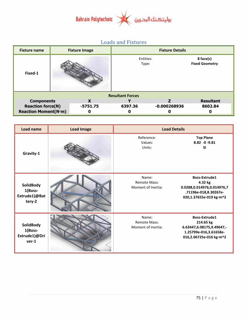
75 | P a g e
Loads and Fixtures
Fixture name Fixture Image Fixture Details
Fixed-1
Entities: 8 face(s) Type: Fixed Geometry
Resultant Forces Components X Y Z Resultant
Reaction force(N) -5751.75 6397.36 -0.000268936 8602.84
Reaction Moment(N·m) 0 0 0 0
Load name Load Image Load Details
Gravity-1
Reference: Top Plane Values: 8.82 -0 -9.81 Units: SI
SolidBody 1(Boss-
Extrude1)@Battery-2
Name: Boss-Extrude1 Remote Mass: 4.32 kg
Moment of Inertia: 0.0288,0.014976,0.014976,7.71196e-018,8.30267e-
020,1.37655e-019 kg·m^2
SolidBody 1(Boss-
Extrude1)@Driver-1
Name: Boss-Extrude1 Remote Mass: 214.65 kg
Moment of Inertia: 6.63447,6.08175,9.49647,-1.25799e-016,3.61658e-
016,2.06725e-016 kg·m^2
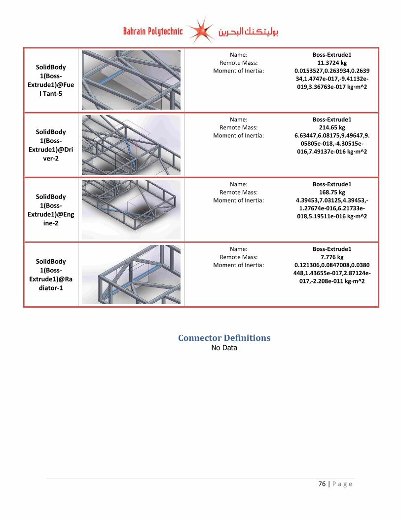
76 | P a g e
SolidBody 1(Boss-
Extrude1)@Fuel Tant-5
Name: Boss-Extrude1 Remote Mass: 11.3724 kg
Moment of Inertia: 0.0153527,0.263934,0.263934,1.4747e-017,-9.41132e-019,3.36763e-017 kg·m^2
SolidBody 1(Boss-
Extrude1)@Driver-2
Name: Boss-Extrude1 Remote Mass: 214.65 kg
Moment of Inertia: 6.63447,6.08175,9.49647,9.05805e-018,-4.30515e-
016,7.49137e-016 kg·m^2
SolidBody 1(Boss-
Extrude1)@Engine-2
Name: Boss-Extrude1 Remote Mass: 168.75 kg
Moment of Inertia: 4.39453,7.03125,4.39453,-1.27674e-016,6.21733e-
018,5.19511e-016 kg·m^2
SolidBody 1(Boss-
Extrude1)@Radiator-1
Name: Boss-Extrude1 Remote Mass: 7.776 kg
Moment of Inertia: 0.121306,0.0847008,0.0380448,1.43655e-017,2.87124e-
017,-2.208e-011 kg·m^2
Connector Definitions No Data
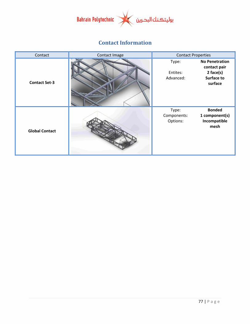
77 | P a g e
Contact Information
Contact Contact Image Contact Properties
Contact Set-3
Type: No Penetration contact pair
Entites: 2 face(s) Advanced: Surface to
surface
Global Contact
Type: Bonded Components: 1 component(s)
Options: Incompatible mesh
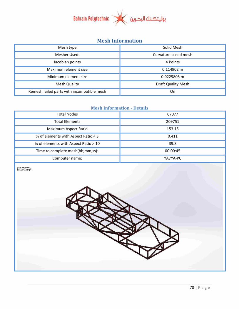
78 | P a g e
Mesh Information Mesh type Solid Mesh
Mesher Used: Curvature based mesh
Jacobian points 4 Points
Maximum element size 0.114902 m
Minimum element size 0.0229805 m
Mesh Quality Draft Quality Mesh
Remesh failed parts with incompatible mesh On
Mesh Information - Details
Total Nodes 67077
Total Elements 209751
Maximum Aspect Ratio 153.15
% of elements with Aspect Ratio < 3 0.411
% of elements with Aspect Ratio > 10 39.8
Time to complete mesh(hh;mm;ss): 00:00:45
Computer name: YA7YA-PC
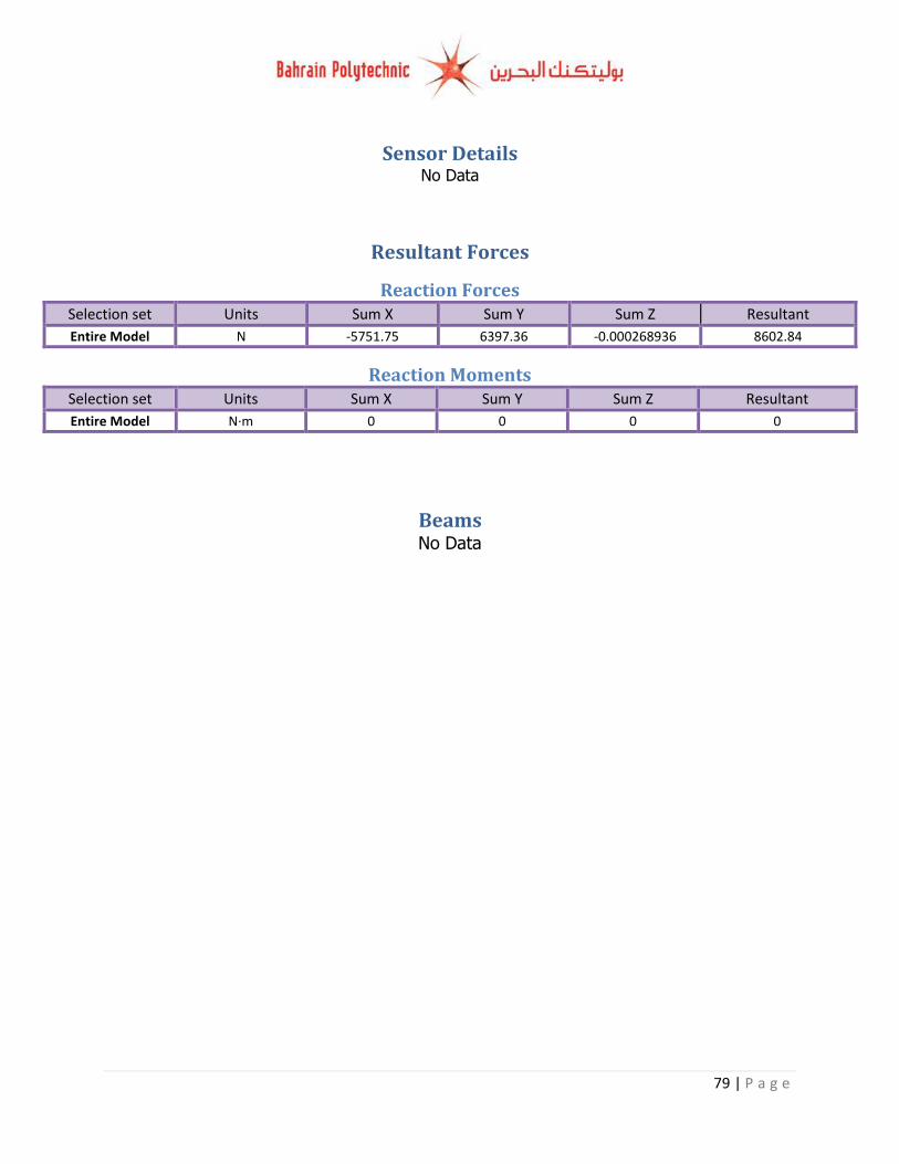
79 | P a g e
Sensor Details No Data
Resultant Forces
Reaction Forces Selection set Units Sum X Sum Y Sum Z Resultant
Entire Model N -5751.75 6397.36 -0.000268936 8602.84
Reaction Moments Selection set Units Sum X Sum Y Sum Z Resultant
Entire Model N·m 0 0 0 0
Beams No Data
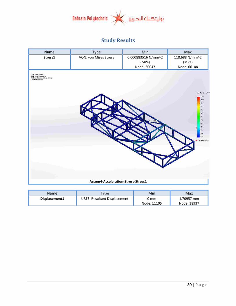
80 | P a g e
Study Results
Name Type Min Max Stress1 VON: von Mises Stress 0.000883516 N/mm^2
(MPa) Node: 60047
118.688 N/mm^2 (MPa)
Node: 66108
Assem4-Acceleration-Stress-Stress1
Name Type Min Max Displacement1 URES: Resultant Displacement 0 mm
Node: 11105 1.70957 mm Node: 38937
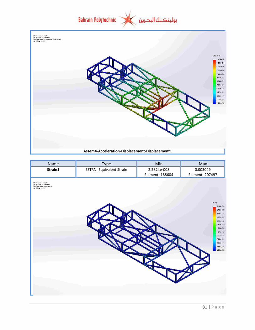
81 | P a g e
Assem4-Acceleration-Displacement-Displacement1
Name Type Min Max Strain1 ESTRN: Equivalent Strain 2.5824e-008
Element: 188604 0.003049
Element: 207497
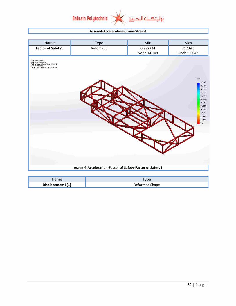
82 | P a g e
Assem4-Acceleration-Strain-Strain1
Name Type Min Max Factor of Safety1 Automatic 0.232324
Node: 66108 31209.6
Node: 60047
Assem4-Acceleration-Factor of Safety-Factor of Safety1
Name Type Displacement1{1} Deformed Shape
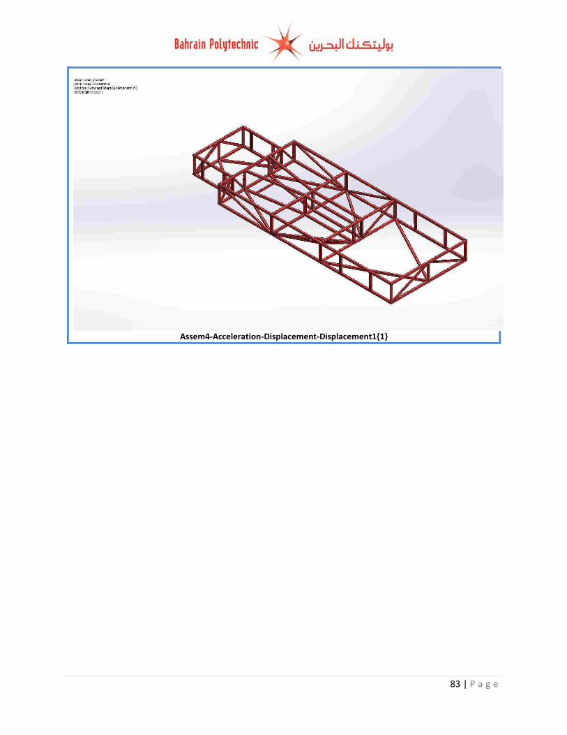
83 | P a g e
Assem4-Acceleration-Displacement-Displacement1{1}
84 | P a g e
Reference: BASIC WELDING. (n.d.). Retrieved from
http://www.gcs.k12.nc.us/cms/lib05/NC01000806/Centricity/Domain/524/ArcWeldingBasics.pptx
Brazing practice. (2013). Retrieved from Brazing practice:
http://upload.wikimedia.org/wikipedia/commons/6/6b/Brazing_practice.jpg Cambridge), B. C. (2014). cantilever beam. Retrieved from doitpoms:
http://www.doitpoms.ac.uk/tlplib/thermal-expansion/printall.php directindustry. (2011). Retrieved from directindustry: http://img.directindustry.com/images_di/photo-
g/gas-blow-torches-108305-3418019.jpg ductile and brittle fracture. (2008). Retrieved from sv.vt:
http://www.sv.vt.edu/classes/MSE2094_NoteBook/97ClassProj/exper/bailey/www/bailey.html Ductile Fracture 2. (2013). Retrieved from hsctut:
http://www.hsctut.materials.unsw.edu.au/Crack%20Theory/cracktheory2b.htm# Duralumin. (2013). Retrieved from spaceflight:
http://www.spaceflight.esa.int/impress/text/education/Images/MechanicalProperties/Image007.png
fatigue. (n.d.). Retrieved from marinediesels:
http://www.marinediesels.info/2_stroke_engine_parts/Other_info/fatigue.htm Funderburk, R. S. (1998). Key Concepts in Welding Engineering. Retrieved from jflf:
http://www.jflf.org/pdfs/papers/keyconcepts4.pdf Harbin, W. (2013, September 24). vehicle load transfer. Retrieved from slideshare:
http://www.slideshare.net/billharbin/vehicle-load-transfer-parts-iiimar13 hotrod. (2010). Retrieved from hotrod: http://stblogs.hotrod.com/files/2011/03/Eastwoods-TIG-200-
DIY-TIG-Welder-623x597.jpg Introduction to Finite Element Analysis. (2008). Retrieved from sv:
http://www.sv.vt.edu/classes/MSE2094_NoteBook/97ClassProj/num/widas/history.html Is Brazing Better? (2005). Retrieved from assemblymag: http://www.assemblymag.com/articles/83151-
is-brazing-better Khan, M. (2007). Welding Science and Technology. New Delhi: New Age International (P). mechanical-engineering. (2011). Retrieved from mechanical-engineering: http://mechanical-
engineering.in/forum/uploads/blog-0068290001380538246.jpg
85 | P a g e
Method Of Joining Materials. (2012). Retrieved from rewardinglearning: http://www.rewardinglearning.org.uk/common/includes/microsite_doc_link.aspx?docid=10363-1
Pedalarm Bruch. (2005). Retrieved from wikipedia:
https://en.wikipedia.org/wiki/File:Pedalarm_Bruch.jpg PWHT Determines the Quality of Weldments. (2012). Retrieved from kobelco: http://www.kobelco-
welding.jp/education-center/abc/ABC_2001-02.html sciepub. (n.d.). fig13. Retrieved from sciepub: http://pubs.sciepub.com/ajme/1/7/24/image/fig13.png siliconfareast. (2005). joining processes. Retrieved from siliconfareast:
http://www.siliconfareast.com/joining-processes.htm Suranaree University of Technology. (2007, may). Creep and stress rupture. Retrieved from sut:
http://eng.sut.ac.th/metal/images/stories/pdf/13_Creep_and_stress_rupture.pdf tech. (n.d.). Retrieved from tech: http://www.tech.plym.ac.uk/sme/mech330/join1.htm TIG vs. MIG Welding - What's the Difference? (n.d.). Retrieved from used robots: http://www.used-
robots.com/articles/viewing/tig-vs-mig-welding-what-s-the-difference Timber deflection. (N.d.). Retrieved from roymech:
http://www.roymech.co.uk/images/Timber_deflection.gif