Embed Size (px)
Citation preview
Meccanica (2007) 42:451–463DOI 10.1007/s11012-007-9064-8
Assessing joint angles in human hand via optical trackingdevice and calibrating instrumented glove
M. Veber · T. Bajd · M. Munih
Received: 26 July 2006 / Accepted:25 January 2007 / Published online: 2 June 2007© Springer Science+Business Media B.V. 2007
Abstract The aim of this paper is to present a methodfor assessing joint angles in a human hand: a methodsuitable for the calibration of an instrumented glove.The method is based on an optical tracking device andan inverse-kinematic model of the human hand. Itrequires only one reflective marker to be attached toeach finger and three on the dorsal aspect of the handin order to assess angles in finger joints. A further threemarkers are needed to calculate angles in thumb joints.Joint angles assessed through inverse kinematics andwith the calibrated glove were validated against ref-erence angles calculated from the centers of rotationof the joints while measuring the finger movementswith multiple markers. In fingers, the mean differencebetween the reference angles and the angles assessedby the glove did not exceed ±7◦ when the proposedmodel-based method was used to calibrate the glove.For the thumb the mean error did not exceed ±5◦ whenthe reference method was used to calibrate the glove.
Keywords Finger joint angles · Kinematic model ofthe hand · Instrumented glove · Calibration
Abbreviations
D-H Denavit-HartenbergDOF Degrees of freedom
M. Veber (B) · T. Bajd · M. MunihFaculty of Electrical Engineering, Laboratory of Roboticsand Biomedical Engineering, University of Ljubljana,Trzaska c.25, 1000 Ljubljna, Sloveniae-mail: [email protected]
MCP Metacarpophalangeal jointPIP Proximal interphalangeal jointDIP Distal interphalangeal jointCMC carpometacarpal jointIP Interphalangeal jointCoR Center(s) of rotationf-e Flexion–extensionab-ad Abduction–adduction
1 Introduction
The human hand is a versatile system with 25 degrees offreedom [15]. The incredible adaptability of the humanhand to specific requirements raises the question of howthe joints are controlled in order to perform so manydifferent tasks. In contrast to many studies related tothe control of joints of multi-fingered robotic grippers[3,17,14], studies related to the task-oriented control ofjoints in a human hand are scarce because a generallyaccepted approach for accurate noninvasive assessmentof hand kinematics is not available.
The aim of this paper is to propose a method basedon an optical tracking system and an inverse-kinematicmodel of the human hand that calculates joint angles inthumb and fingers from the positions of a small num-ber of reflective markers attached to the surface of thehand. The method will be applied to the calibration ofan instrumented glove, which is intended to be used as acomplementary system overcoming the main drawbackof the optical tracking system — occlusion of markers
123
452 Meccanica (2007) 42:451–463
during manipulative tasks. The proposed method andthe calibrated glove will be compared with referencemethods [23,6,16] that require a larger set of markersin order to assess angles in thumb and finger joints.
Optical tracking is a well-established technique [12]that does not hinder the movement of the human bodyas for instance exoskeletons. It enables the measure-ment of body kinematics by tracking reflective markersplaced over bony landmarks. Because of its accuracy,the method can be considered as a reference for recon-struction of kinematics. The body’s kinematics are mod-eled by rigid bodies linked with joints. In general, threenoncollinear markers have to be attached to each rigidbody to reconstruct its motion in 3D.
The difficulty in capturing hand kinematics origi-nates from the relatively large number of degrees offreedom concentrated in a very small place [16]. Thisproblem can be to some extent reduced by consid-ering the characteristic patterns of finger motion, sothat fewer markers can be used. Skin artifacts that arelarge compared with the distances between markerscan make the reconstruction of a frame attached to aphalange even more difficult. In addition, the range ofmotion of some joints is very small.
Another drawback of optical tracking is the occlu-sion of markers. This deficiency becomes even moreobvious with a large number of markers and is the mainreason why optical tracking systems are not widelyused for the assessment of hand kinematics. In mag-netic tracking systems there is no problem with occlu-sion, but in currently available commercial systemsmarkers are too big to be attached appropriately to fin-gers or else only the use of a small number (usuallyone or two) of markers is supported. There is also aproblem of interference from the environment in somemagnetic tracking systems.
Finger kinematics can also be assessed by instru-mented gloves, which have been used in many experi-ments [19]. However, in most cases the raw data fromthe gloves were used. For instance, in one study aninstrumented glove was used when analyzing grasp-ing sequences by hidden Markov models [2]. A sim-ilar problem was solved elsewhere with fuzzy-logicdecision functions [1]. In such experiments where aglove is used, significant effort is devoted to compen-sating for the offset in the raw response, which occurswhen the bend sensors are fully extended. This off-set is not repeatable for different attachments, not evenwhen used with the same hand. By carrying out a set
of specific hand movements, an estimate of offset canbe provided and the active range of analog-to-digitalconverters established. For a hand with a known rangeof finger-joint motions, rough estimates of the timecourses of joint angles could be obtained [20] if theresponses of the bend sensors were linear. We are notaware of any article comparing angles in finger jointsassessed using an instrumented glove with the anglesobtained by using a reliable reference method. Gloverepeatability was studied by Dipietro et al. [8], whereerrors related to donning and doffing were analyzed, al-though only for specific postures. In another study [22],a glove mounted on an artificial hand was calibrated.This study provided a good estimate of the glove accu-racy; but because a model, instead of a real human hand,was used in the experiment, some errors such as skinmovement artifacts were not taken into account. It isalso important to note that this approach could not beused for calibration of a glove in human applicationswhere the kinematics of hands with diverse propertiesare to be assessed.
The paper begins by presenting a kinematic model ofthe human hand, which can be scaled according to thehand’s external dimensions. In the sections that follow,methods are presented for assessing angles in fingerjoints through inverse kinematics and from the centersof rotation (CoR) of joints. Both methods are appliedto the calibration of an instrumented glove. Finally, theangles assessed through the use of inverse kinematicsand with the calibrated glove are compared with thereference angles calculated from the CoR of joints.
2 Methods
2.1 Kinematic model of the hand
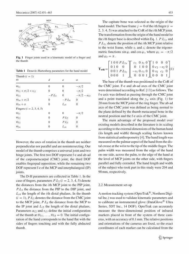
Finger and thumb kinematics were described withDenavit–Hartenberg notation (D-H) [7]. The coordi-nate frames placed according to the rules stated by D-Hare presented in Fig. 1. The z-axis of a frame attachedto the wrist is aligned with the middle finger.
Four degrees of freedom (DOF) are used to describeeach finger [21]: two for the metacarpophalangeal joint(MCP), flexion–extension (f-e) and abduction–adduction (ab-ad); and two for the proximal interpha-langeal (PIP) and the distal interphalangeal (DIP) jointf-e. It has been shown that five DOF are necessary tomodel key kinematic features of the human thumb [5].
123
Meccanica (2007) 42:451–463 453
DIP
PIP
MCP
PJi1
PJi3
PJi2
Li4
MCPIP
CMC
z00
z05
z01
z02
z03z04
x01
x02
x03
x04x05
x00
θ0
xw
xi0 ,xi1 yw
zw
yi0, zi1yi1
xi2 yi2
zi0
zi2
xi3 yi3zi3
yi4
xi4zi4
y02
y03
y04
y05 PJ13PJ14
L15
Fig. 1 Finger joints used in a kinematic model of a finger andthe thumb
Table 1 Denavit–Hartenberg parameters for the hand model
Thumb (i = 1)� d a α
�i1 0 0 −π/2
�i2 + π/2 + εi2 0 0 −π/2
�i3 −P Ji3 0 −π/2 − αi3
�i4 + π/2 0 −P Ji4 0
�i5 + π 0 Li5 0
Fingers (i = 2, 3, 4, 5)
�i1 0 0 −π/2
�i2 0 P Ji2 0
�i3 0 P Ji3 0
�i4 0 Li4 0
However, the axes of rotation in the thumb are neitherperpendicular nor parallel and are nonintersecting. Ourmodel of the thumb comprises a universal joint and twohinge joints. The first two DOF represent f-e and ab-adof the carpometacarpal (CMC) joint; the third DOFenables fingerpad opposition; while the remaining twoDOF represent f-e of the MCP and interphalangeal (IP)joints.
The D-H parameters are collected in Table 1. In thecase of fingers, parameters P Ji2 (i = 2, 3, 4, 5) denotethe distances from the i th MCP joint to the PIP joint,P Ji3 the distance from the PIP to the DIP joint, andLi4 the length of the i th distal phalanx. In the thumb(i = 1), P Ji3 denotes the distance from the CMC jointto the MCP joint, P Ji4 the distance from the MCP tothe IP joint and Li5 the length of the distal phalanx.Parameters αi2 and εi3 define the initial configurationof the thumb at �i1, . . . , �i5 = 0. The initial configu-ration of the hand corresponds to the hand flat with thesides of fingers touching and with the fully abductedthumb.
The capitate bone was selected as the origin of thehand model. The base frame j = 0 of the i th finger (i =2, 3, 4, 5) was attached to the CoR of the i th MCP joint.The transformation from the origin of the hand model tothe i th finger base is described within Eq. 1. P Ji1x andP Ji1z denote the position of the i th MCP joint relativeto the wrist frame, while si and ci denote the trigono-metric functions sin ϕi and cos ϕi , where ϕ1 = −π/2and ϕ2 = π .
Tw0i =
⎡⎢⎢⎣
1 0 0 P Ji1x
0 1 0 00 0 1 P Ji1z
0 0 0 1
⎤⎥⎥⎦
⎡⎢⎢⎣
c1 0 s1 00 1 0 0
−s1 0 c1 00 0 0 1
⎤⎥⎥⎦
⎡⎢⎢⎣
1 0 0 00 c2 −s2 00 s2 c2 00 0 0 1
⎤⎥⎥⎦(1)
The base of the thumb was positioned to the CoR ofthe CMC joint. F-e and ab-ad axes of the CMC jointwere determined according to Ref. [13] as follows. Thef-e axis was defined as passing through the CMC jointand a point translated along the yw axis (Fig. 1) for20 mm from the MCP joint of the ring finger. The ab-adaxis of the CMC joint was defined as being normal tothe plane defined by the thumb metacarpal bone in theneutral position and the f-e axis of the CMC joint.
The main advantage of the proposed model overexisting models described in the literature is its scalingaccording to the external dimensions of the human hand(its length and width) through scaling factors knownfrom statistical anthropometry [4]. The hand length wasmeasured on the palmar aspect of the hand from the dis-tal crease at the wrist to the tip of the middle finger. Thepalm width was measured from the edge of the handon one side, across the palm, to the edge of the hand atthe level of MCP joints on the other side, with fingersparallel and fully extended. The hand length and widthof the subject who took part in this study were 204 and90 mm, respectively.
2.2 Measurement set-up
A motion tracking system (OptoTrak®, Northern Digi-tal Inc.) was used to validate kinematic parameters andto calibrate an instrumented glove (DataGlove® UltraSeries, 5DT Inc., 14 DOF). OptoTrak can accuratelymeasure the three-dimensional position of infraredmarkers placed in front of the system of three cam-eras, with an accuracy of 0.1 mm. The relative positionsand orientations of the cameras are fixed, so the exactcoordinates of each marker can be calculated from the
123
454 Meccanica (2007) 42:451–463
known geometry of the camera set-up. The system iscalibrated before each measurement session with thehelp of a calibration plate having eight embedded mark-ers. The position and orientation of the plate placed infront of the cameras define the coordinate system inwhich marker positions are expressed.
A DataGlove has 14 fiber-optic bend sensors thatmeasure f-e angles in the MCP and PIP joints as wellas ab-ad angles between fingers. Two sensors are usedto measure f-e angles of the thumb IP and CMC joints,while one sensor measures the ab-ad angle of the thumb.The system interfaces with the computer via a USBport. It features a 12-bit analog-digital converter, but theresolution of the optical bend sensors is much smaller,typically below 10 bits.
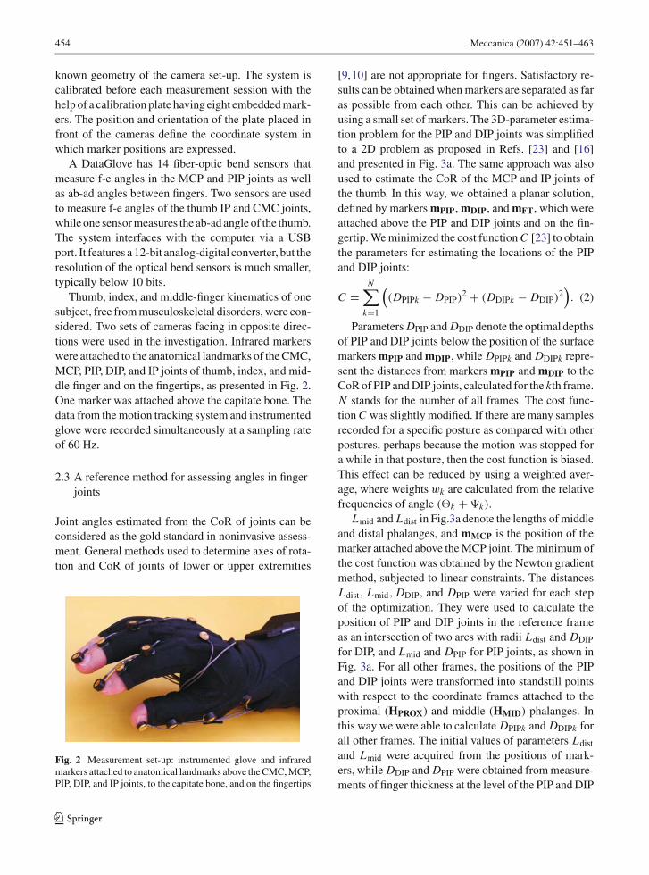
Thumb, index, and middle-finger kinematics of onesubject, free from musculoskeletal disorders, were con-sidered. Two sets of cameras facing in opposite direc-tions were used in the investigation. Infrared markerswere attached to the anatomical landmarks of the CMC,MCP, PIP, DIP, and IP joints of thumb, index, and mid-dle finger and on the fingertips, as presented in Fig. 2.One marker was attached above the capitate bone. Thedata from the motion tracking system and instrumentedglove were recorded simultaneously at a sampling rateof 60 Hz.
2.3 A reference method for assessing angles in fingerjoints
Joint angles estimated from the CoR of joints can beconsidered as the gold standard in noninvasive assess-ment. General methods used to determine axes of rota-tion and CoR of joints of lower or upper extremities
Fig. 2 Measurement set-up: instrumented glove and infraredmarkers attached to anatomical landmarks above the CMC, MCP,PIP, DIP, and IP joints, to the capitate bone, and on the fingertips
[9,10] are not appropriate for fingers. Satisfactory re-sults can be obtained when markers are separated as faras possible from each other. This can be achieved byusing a small set of markers. The 3D-parameter estima-tion problem for the PIP and DIP joints was simplifiedto a 2D problem as proposed in Refs. [23] and [16]and presented in Fig. 3a. The same approach was alsoused to estimate the CoR of the MCP and IP joints ofthe thumb. In this way, we obtained a planar solution,defined by markers mPIP, mDIP, and mFT, which wereattached above the PIP and DIP joints and on the fin-gertip. We minimized the cost function C [23] to obtainthe parameters for estimating the locations of the PIPand DIP joints:
C =N∑
k=1
((DPIPk − DPIP)2 + (DDIPk − DDIP)2
). (2)
Parameters DPIP and DDIP denote the optimal depthsof PIP and DIP joints below the position of the surfacemarkers mPIP and mDIP, while DPIPk and DDIPk repre-sent the distances from markers mPIP and mDIP to theCoR of PIP and DIP joints, calculated for the kth frame.N stands for the number of all frames. The cost func-tion C was slightly modified. If there are many samplesrecorded for a specific posture as compared with otherpostures, perhaps because the motion was stopped fora while in that posture, then the cost function is biased.This effect can be reduced by using a weighted aver-age, where weights wk are calculated from the relativefrequencies of angle (�k + �k).
Lmid and Ldist in Fig.3a denote the lengths of middleand distal phalanges, and mMCP is the position of themarker attached above the MCP joint. The minimum ofthe cost function was obtained by the Newton gradientmethod, subjected to linear constraints. The distancesLdist, Lmid, DDIP, and DPIP were varied for each stepof the optimization. They were used to calculate theposition of PIP and DIP joints in the reference frameas an intersection of two arcs with radii Ldist and DDIP
for DIP, and Lmid and DPIP for PIP joints, as shown inFig. 3a. For all other frames, the positions of the PIPand DIP joints were transformed into standstill pointswith respect to the coordinate frames attached to theproximal (HPROX) and middle (HMID) phalanges. Inthis way we were able to calculate DPIPk and DDIPk forall other frames. The initial values of parameters Ldist
and Lmid were acquired from the positions of mark-ers, while DDIP and DPIP were obtained from measure-ments of finger thickness at the level of the PIP and DIP
123

Meccanica (2007) 42:451–463 455
mMCP
MCP
Tk
Href
Hd
mDIP
Hk
mFT
mDIP
mPIP mMCP
DDIP
DPIP
Ldist
Lmid
θk DIP
PIPMCP
ψk
DDIPi
DPIPi
HPROX
HMID
b
mkp
O
rp
kp
a
c
vCoR
Fig. 3 Assessment of centers of rotation of the PIP and DIP joints of fingers and the MCP and IP joints of the thumb [23] (a), MCPjoints of fingers [16] (b), and CMC joint of the thumb [6] (c)
joints. The constraints guaranteed that the optimizationroutine would be able to cope with each posture.
For the MCP joint, improved results can be obtainedby using the marker mPIP, which is distant from thejoint [16]. We modified the proposed method, as shownin Fig. 3b. The PIP joint was kept motionless (indi-cated by a dotted line). The orientation of the coordi-nate frame (Href ) was reconstructed for the referenceframe from the positions of markers mMCP and mDIP
attached to the observed finger, and from the markerattached to the MCP joint of the adjacent finger. Href
was positioned to the location of mDIP. The CoR ofMCP joint was found by minimizing the cost functiondefined as follows [16]:
C =N∑
k=1
wk‖TkCMCP − CMCP‖. (3)
Tk denotes a transformation matrix that moves the coor-dinate frame (Href ) from the initial (k = 1) to the kth(k = 2, . . . , N ) pose, while (CMCP) represents a pointthat is invariant to transformations (Tk) and can there-fore be taken for the CoR of the MCP joint. The CoR ofMCP joints were expressed relative to the coordinateframe of the hand dorsum (Hd). The weights wk in thecost function were included for reasons similar to thosefor estimating the CoR of PIP and DIP joints. The wk
were estimated from the relative frequencies of (Hk)rotation with respect to (Hd).
The average CoR of the CMC joint was estimatedby minimizing a cost function C that assumes that Pmarkers attached to the carpal bone maintain a constantdistance r p from the CoR of the CMC joint (vCoR)
(Fig. 3c):
C =P∑
p=1
N∑k=1
(√mp
k − vCoR − r p)2
. (4)
The spherical fit should have minimal variation εpk in
the separation length between the CoR of the CMCjoint and the pth marker position mp
k at the kth frame,for all k (k = 1, . . . , N ).
In Ref. [6] an optimal closed-form solution to thisproblem is provided, where the constrained least-squaressolution is obtained by using a carefully chosen nor-malization scheme. The method performs well evenfor joints with small ranges of motion.
The parameters for the reconstruction of the CoRof joints in the fingers (CMCP, Ldist, Lmid, DDIP, andDPIP) were estimated from the signals recorded for f-eof the MCP joints with extended PIP and DIP joints,and f-e of PIP and DIP joints at fixed f-e in MCP joints.The CMC joint was kept motionless when assessingparameters for reconstructing the MCP and IP joints ofthe thumb (Lprox, Ldist, DMCP, and DIP). The CoRof the CMC joint was estimated from circumductionof the thumb.
2.4 A method for assessing angles through inversekinematics
Joint angles in fingers were obtained by solving theinverse-kinematics problem of a two-link manipulator[18]. Angles related to the ab-ad and f-e angles in theMCP and f-e angles in the PIP joints were obtainedfrom the known position of a marker attached abovethe DIP joint. In human fingers, the movement of PIP
123
456 Meccanica (2007) 42:451–463
p
q
CMCMCP
IP
PJ13
PJ14
L15
4
5
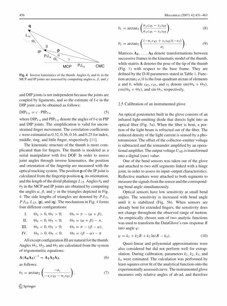
Fig. 4 Inverse kinematics of the thumb. Angles θ4 and θ5 in theMCP and IP joints are assessed by computing angles α, β, and γ
and DIP joints is not independent because the joints arecoupled by ligaments, and so the estimate of f-e in theDIP joint can be obtained as follows:
DIPf-e = c · PIPf-e (5)
where DIPf-e and PIPf-e denote the angles of f-e in PIPand DIP joints. The simplification is valid for uncon-strained finger movement. The correlation coefficientsc were estimated as 0.32, 0.36, 0.16, and 0.25 for index,middle, ring, and little finger, respectively [11].
The kinematic structure of the thumb is more com-plicated than for fingers. The thumb is modeled as aserial manipulator with five DOF. In order to assessjoint angles through inverse kinematics, the positionand orientation of the fingertip are measured with theoptical tracking system. The position p of the IP joint iscalculated from the fingertip position q, its orientation,and the length of the distal phalange L15. Angles θ4 andθ5 in the MCP and IP joints are obtained by computingthe angles α, β, and γ in the triangles depicted in Fig.4. The side lengths of triangles are denoted by P J13,P J14, L15, |p|, and |q|. The mechanism in Fig. 4 formsfour different configurations:
I. �4 > 0,�5 > 0; �5 = π − (α + β),
II. �4 < 0,�5 < 0; �5 = (α + β) − π,
III. �4 < 0,�5 > 0; �5 = π − (β − α),
IV. �4 > 0,�5 < 0; �5 = (β − α) − π
All except configuration III are natural for the thumb.Angles �1, �2, and �3 are calculated from the systemof trigonometric equations:
A(A4A5)−1 = A1A2A3, (6)
as follows:
θ3 = arctan2
( −az
−szc45 − nzs45
), (7)
θ1 = arctan2
(nyc45 − sys45
nx c45 − sx s45
), (8)
θ1 = arctan2
((−nzc45 + szs45)(−s3)
az
). (9)
Matrices A1, . . . , A5 denote transformations betweensuccessive frames in the kinematic model of the thumb,while matrix A denotes the pose of the tip of the thumb(Fig. 1) with respect to the base frame. They aredefined by the D-H parameters stated in Table 1. Func-tion arctan2 a/b is the four-quadrant arctan of elementsa and b, while s45, c45, and s3 denote sin(�4 + �5),cos(�4 + �5), and sin �3, respectively.
2.5 Calibration of an instrumented glove
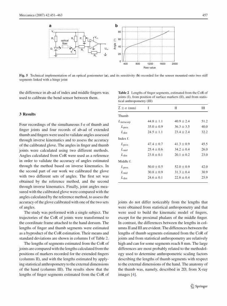
An optical goniometer built in the glove consists of aninfrared light-emitting diode that directs light into anoptical fiber (Fig. 5a). When the fiber is bent, a por-tion of the light beam is refracted out of the fiber. Thereduced density of the light current is sensed by a pho-totransistor. The offset of the collector–emitter voltageis subtracted and the remainder amplified by an opera-tional amplifier. The output voltage UAD is transformedinto a digital (raw) value.
One of the bend sensors was taken out of the gloveand attached to two stiff segments linked with a hingejoint, in order to assess its input–output characteristics.Reflective markers were attached to both segments tomeasure the signals from the sensor and the correspond-ing bend angle simultaneously.
Optical sensors have low sensitivity at small bendangles. The sensitivity is increased with bend angleuntil it is stabilized (Fig. 5b). When sensors arealready bent for extended fingers, the sensitivity doesnot change throughout the observed range of motion.An empirically chosen sum of two analytic functionswas used to transform the DataGlove’s raw response Rinto angle ϕ:
ϕ = k1 + k2 R + k3 ln(R − k4). (10)
Quasi-linear and polynomial approximations werealso considered but did not perform well for extrap-olation. During calibration, parameters k1, k2, k3, andk4 were estimated. The calculation was performed byleast-squares error fit of the analytical function onto theexperimentally assessed curve. The instrumented glovemeasures only relative angles of ab-ad, and therefore
123
Meccanica (2007) 42:451–463 457
a
-
VCC
R1 R2
R3
R4
+
UAD
VCC
opticalfiber
P1
400 800 1200 1600 20000
20
40
60
80
Raw value
Ang
le(°
)
b
D1
T1
Fig. 5 Technical implementation of an optical goniometer (a), and its sensitivity (b) recorded for the sensor mounted onto two stiffsegments linked with a hinge joint
the difference in ab-ad of index and middle fingers wasused to calibrate the bend sensor between them.
3 Results
Four recordings of the simultaneous f-e of thumb andfinger joints and four records of ab-ad of extendedthumb and fingers were used to validate angles assessedthrough inverse kinematics and to assess the accuracyof the calibrated glove. The angles in finger and thumbjoints were calculated using two different methods.Angles calculated from CoR were used as a referencein order to validate the accuracy of angles estimatedthrough the method based on inverse kinematics. Inthe second part of our work we calibrated the glovewith two different sets of angles. The first set wasobtained by the reference method, and the secondthrough inverse kinematics. Finally, joint angles mea-sured with the calibrated glove were compared with theangles calculated by the reference method, to assess theaccuracy of the glove calibrated with one of the two setsof angles.
The study was performed with a single subject. Thetrajectories of the CoR of joints were transformed tothe coordinate frame attached to the hand dorsum. Thelengths of finger and thumb segments were estimatedas a byproduct of the CoR estimation. Their means andstandard deviations are shown in columns I of Table 2.
The lengths of segments estimated from the CoR ofjoints are compared with the lengths calculated from thepositions of markers recorded for the extended fingers(columns II), and with the lengths estimated by apply-ing statistical anthropometry to the external dimensionsof the hand (columns III). The results show that thelengths of finger segments estimated from the CoR of
Table 2 Lengths of finger segments, estimated from the CoR ofjoints (I), from position of surface markers (II), and from statis-tical anthropometry (III)
L ± σ (mm) I II III
Thumb
Lmetacarp 44.8 ± 1.1 40.9 ± 2.4 51.2
Lprox 35.0 ± 0.9 36.3 ± 3.5 40.0
Ldist 24.5 ± 1.1 23.4 ± 2.4 32.2
Index f.
Lprox 47.4 ± 0.7 41.3 ± 0.9 45.5
Lmid 25.4 ± 0.6 34.2 ± 0.4 26.0
Ldist 23.8 ± 0.1 20.1 ± 0.2 23.0
Middle f.
Lprox 50.0 ± 0.5 52.0 ± 0.9 42.0
Lmid 30.8 ± 0.9 31.3 ± 0.4 30.9
Ldist 24.6 ± 0.1 22.8 ± 0.4 25.9
joints do not differ noticeably from the lengths thatwere obtained from statistical anthropometry and thatwere used to build the kinematic model of fingers,except for the proximal phalanx of the middle finger.In contrast, the differences between the lengths in col-umns II and III are evident. The differences between thelengths of thumb segments estimated from the CoR ofjoints and from statistical anthropometry are relativelyhigh and can for some segments reach 8 mm. The largedifferences are most probably related to the methodol-ogy used to determine anthropometric scaling factorsdescribing the lengths of thumb segments with respectto the external dimensions of the hand. The anatomy ofthe thumb was, namely, described in 2D, from X-rayimages [4].
123
458 Meccanica (2007) 42:451–463
d
c
b
0
40
80
PIP
f-e
()
0 1 2 30
20
40
DIP
f-e
()
t (s)
0
20
40
60M
CP
f-e
()
-30
-20
-10
0
MC
Pab
-ad
()a
CM
Cf-
e(
)
0
30
60
CM
Cab
-ad
()
0
20
40
MC
Pf-
e(
)
0
30
60
IPf-
e(
)0 1 2 3
t (s)
h
g
f
e ref invref inv
0
204060
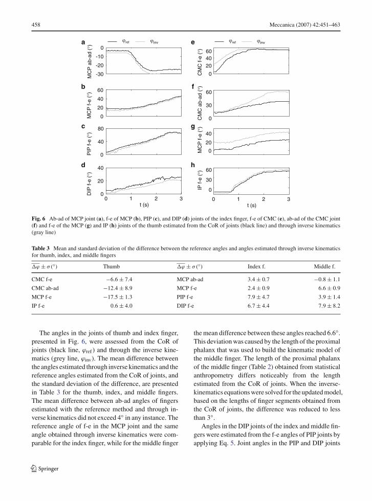
Fig. 6 Ab-ad of MCP joint (a), f-e of MCP (b), PIP (c), and DIP (d) joints of the index finger, f-e of CMC (e), ab-ad of the CMC joint(f) and f-e of the MCP (g) and IP (h) joints of the thumb estimated from the CoR of joints (black line) and through inverse kinematics(gray line)
Table 3 Mean and standard deviation of the difference between the reference angles and angles estimated through inverse kinematicsfor thumb, index, and middle fingers
�ϕ ± σ(◦) Thumb �ϕ ± σ(◦) Index f. Middle f.
CMC f-e −6.6 ± 7.4 MCP ab-ad 3.4 ± 0.7 −0.8 ± 1.1
CMC ab-ad −12.4 ± 8.9 MCP f-e 2.4 ± 0.9 6.6 ± 0.9
MCP f-e −17.5 ± 1.3 PIP f-e 7.9 ± 4.7 3.9 ± 1.4
IP f-e 0.6 ± 4.0 DIP f-e 6.7 ± 4.4 7.9 ± 8.2
The angles in the joints of thumb and index finger,presented in Fig. 6, were assessed from the CoR ofjoints (black line, ϕref ) and through the inverse kine-matics (grey line, ϕinv). The mean difference betweenthe angles estimated through inverse kinematics and thereference angles estimated from the CoR of joints, andthe standard deviation of the difference, are presentedin Table 3 for the thumb, index, and middle fingers.The mean difference between ab-ad angles of fingersestimated with the reference method and through in-verse kinematics did not exceed 4◦ in any instance. Thereference angle of f-e in the MCP joint and the sameangle obtained through inverse kinematics were com-parable for the index finger, while for the middle finger
the mean difference between these angles reached 6.6◦.This deviation was caused by the length of the proximalphalanx that was used to build the kinematic model ofthe middle finger. The length of the proximal phalanxof the middle finger (Table 2) obtained from statisticalanthropometry differs noticeably from the lengthestimated from the CoR of joints. When the inverse-kinematics equations were solved for the updated model,based on the lengths of finger segments obtained fromthe CoR of joints, the difference was reduced to lessthan 3◦.
Angles in the DIP joints of the index and middle fin-gers were estimated from the f-e angles of PIP joints byapplying Eq. 5. Joint angles in the PIP and DIP joints
123
Meccanica (2007) 42:451–463 459
reconstructed through inverse kinematics are smallerthan the reference angles for the index finger as well asfor the middle finger. The difference originates from theposition of the marker, which cannot be placed in theCoR of the DIP joint but has to go above this joint. Asa consequence, the angles estimated for PIP joints aresmaller. Angles in the DIP joints were not used to cali-brate the glove because the glove did not have bend sen-sors to measure flexion of the distal joints. They wereestimated anyway, to demonstrate that angles in the DIPjoints could indeed be estimated from the angles of PIPjoints for unconstrained finger movement.
When it was applied to the thumb, the inverse-kine-matics method did not give results that were as promis-ing as for fingers. The angles of f-e of the CMC and f-eof the IP joints were acquired with mean error −6.6◦and 0.6◦, respectively. The mean difference betweenthe reference angles and the angles calculated throughinverse kinematics was larger than 17◦ and 12◦ for thef-e angle of the MCP joint and the ab-ad angle ofthe CMC joint. Standard deviations were notable forthe CMC joint, in which they exceeded 7◦. The timecourses of angles in the CMC joint in Fig. 6 (panels e, f)show that the error in the f-e angle assessed through in-verse kinematics decreases with flexion, and the errorin the ab-ad angle increases with the adduction of thethumb. This indicates that the CoR of the CMC jointand its axes of rotation were not chosen in an opti-mal manner when developing a kinematic model of thethumb. Such an optimal choice was in fact not evenpossible. The exact location of the center of rotationand the directions of axes of rotation of the CMC jointcould not be estimated from anthropometric data of thehand that are obtained in 2D. However, the large meanerror (and small standard deviation) estimated for thef-e angle of the MCP joint originates from the errone-ously calculated orientation of the distal phalange. Thereflective marker was attached to the thumbnail, whichis not parallel to the distal phalange. As a result, theposition of the IP joint p was miscalculated from thefingertip position q and orientation (Fig. 4).
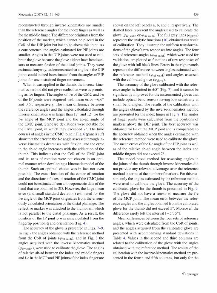
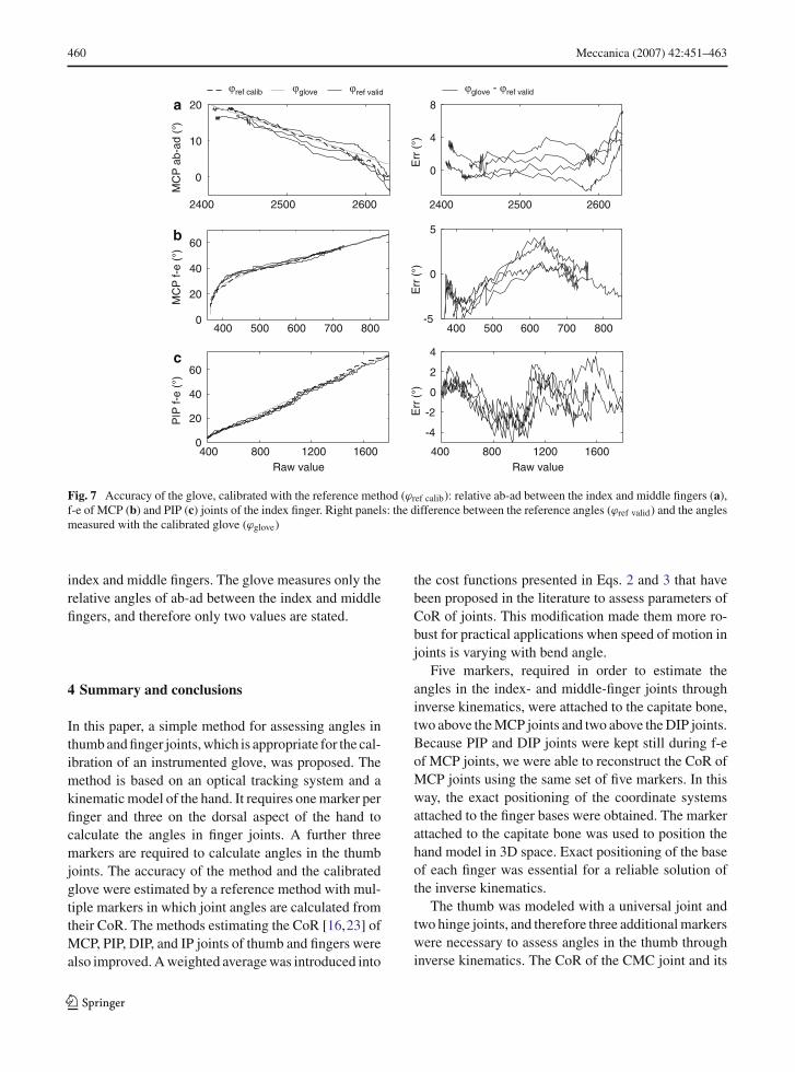
The accuracy of the glove is presented in Figs. 7–9.In Fig. 7 the angles obtained with the reference methodfrom the CoR of joints (ϕref calib), and in Fig. 8 theangles acquired with the inverse kinematics method(ϕinv calib), were used to calibrate the glove. The anglesof relative ab-ad between the index and middle fingersand f-e in the MCP and PIP joints of the index finger are
shown on the left panels a, b, and c, respectively. Thedashed lines represent the angles used to calibrate theglove (ϕref calib or ϕinv calib). The full grey lines (ϕglove)represent the analytic functions (10) obtained as a resultof calibration. They illustrate the uniform transforma-tions of the glove’s raw responses into angles. The foursets of reference angles (ϕref valid), which were used forvalidation, are plotted as functions of raw responses ofthe glove with full black lines. Errors in the right panelsrepresent the difference between angles estimated withthe reference method (ϕref valid) and angles assessedwith the calibrated glove (ϕglove).
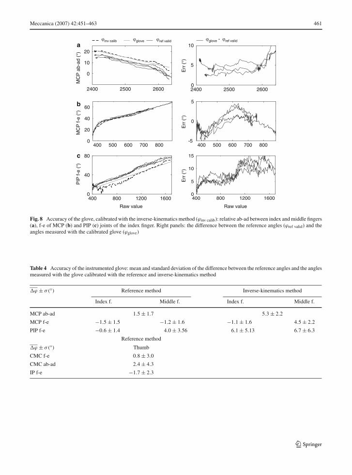
The accuracy of the glove calibrated with the refer-ence angles is limited to ±5◦ (Fig. 7), and it cannot besignificantly improved for the instrumented gloves thatinclude optical bend sensors having low sensitivity atsmall bend angles. The results of the calibration withthe angles obtained by the inverse-kinematics methodare presented for the index finger in Fig. 8. The anglesof finger joints were calculated from the positions ofmarkers above the DIP joint. The best accuracy wasobtained for f-e of the MCP joint and is comparable tothe accuracy obtained when the angles estimated withthe reference method were used to calibrate the glove.The mean errors of the f-e angle of the PIP joint as wellas of the relative ab-ad angle between the index andmiddle fingers did not exceed 7◦.
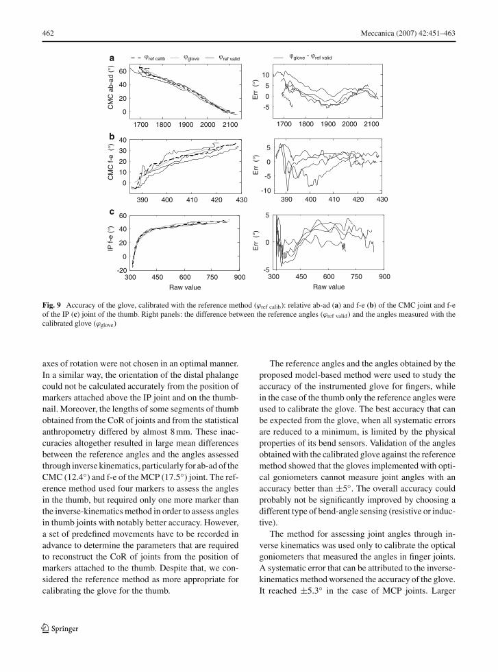
The model-based method for assessing angles inthe joints of the thumb through inverse kinematics didnot provide any relevant advantage over the referencemethod in terms of the number of markers. For this rea-son, only the angles estimated by the reference methodwere used to calibrate the glove. The accuracy of thecalibrated glove for the thumb is presented in Fig. 9.The glove did not have a sensor to measure the f-eof the MCP joint. The mean error between the refer-ence angles and the angles obtained from the calibratedglove for the thumb did not exceed 3◦. Moreover, thedifference rarely left the interval [−5◦, 5◦].
Mean differences between the four sets of referenceangles, which were calculated from the CoR of joints,and the angles acquired from the calibrated glove arepresented with accompanying standard deviations inTable 4. Values in the second and third columns arerelated to the calibration of the glove with the anglesobtained with the reference method. The results of thecalibration with the inverse-kinematics method are pre-sented in the fourth and fifth columns, but only for the
123
460 Meccanica (2007) 42:451–463
b
c
a
0
20
40
60
400 500 600 700 800-5
0
5
Err
(°)
0
20
40
60
400 800 1200 1600
-4
-2
0
2
4
Err
(°)
0
10
20
2400 2500 2600
0
4
8
Err
(°)
400 500 600 700 800
2400 2500 2600
PIP
f-e
(°)
MC
Pab
-ad
(°)
MC
Pf-
e(°
)
Raw value400 800 1200 1600
Raw value
gloveref calib ref valid glove ref valid-
Fig. 7 Accuracy of the glove, calibrated with the reference method (ϕref calib): relative ab-ad between the index and middle fingers (a),f-e of MCP (b) and PIP (c) joints of the index finger. Right panels: the difference between the reference angles (ϕref valid) and the anglesmeasured with the calibrated glove (ϕglove)
index and middle fingers. The glove measures only therelative angles of ab-ad between the index and middlefingers, and therefore only two values are stated.
4 Summary and conclusions
In this paper, a simple method for assessing angles inthumb and finger joints, which is appropriate for the cal-ibration of an instrumented glove, was proposed. Themethod is based on an optical tracking system and akinematic model of the hand. It requires one marker perfinger and three on the dorsal aspect of the hand tocalculate the angles in finger joints. A further threemarkers are required to calculate angles in the thumbjoints. The accuracy of the method and the calibratedglove were estimated by a reference method with mul-tiple markers in which joint angles are calculated fromtheir CoR. The methods estimating the CoR [16,23] ofMCP, PIP, DIP, and IP joints of thumb and fingers werealso improved. A weighted average was introduced into
the cost functions presented in Eqs. 2 and 3 that havebeen proposed in the literature to assess parameters ofCoR of joints. This modification made them more ro-bust for practical applications when speed of motion injoints is varying with bend angle.
Five markers, required in order to estimate theangles in the index- and middle-finger joints throughinverse kinematics, were attached to the capitate bone,two above the MCP joints and two above the DIP joints.Because PIP and DIP joints were kept still during f-eof MCP joints, we were able to reconstruct the CoR ofMCP joints using the same set of five markers. In thisway, the exact positioning of the coordinate systemsattached to the finger bases were obtained. The markerattached to the capitate bone was used to position thehand model in 3D space. Exact positioning of the baseof each finger was essential for a reliable solution ofthe inverse kinematics.
The thumb was modeled with a universal joint andtwo hinge joints, and therefore three additional markerswere necessary to assess angles in the thumb throughinverse kinematics. The CoR of the CMC joint and its
123
Meccanica (2007) 42:451–463 461
b
c
a
5
Raw valueRaw value
2400 2500 2600
0
10
20
MC
Pab
-ad
(°)
2400 2500 26000
5
10
Err
(°)
400 800 1200 16000
40
80
400 800 1200 16000
5
10
15
0
20
40
60
MC
Pf-
e(°
)
400 500 600 700 800-5
0
Err
(°)
400 500 600 700 800
PIP
f-e
()°
Err
(°)
gloveinv calib ref valid glove ref valid-
Fig. 8 Accuracy of the glove, calibrated with the inverse-kinematics method (ϕinv calib): relative ab-ad between index and middle fingers(a), f-e of MCP (b) and PIP (c) joints of the index finger. Right panels: the difference between the reference angles (ϕref valid) and theangles measured with the calibrated glove (ϕglove)
Table 4 Accuracy of the instrumented glove: mean and standard deviation of the difference between the reference angles and the anglesmeasured with the glove calibrated with the reference and inverse-kinematics method
�ϕ ± σ(◦) Reference method Inverse-kinematics method
Index f. Middle f. Index f. Middle f.
MCP ab-ad 1.5 ± 1.7 5.3 ± 2.2
MCP f-e −1.5 ± 1.5 −1.2 ± 1.6 −1.1 ± 1.6 4.5 ± 2.2
PIP f-e −0.6 ± 1.4 4.0 ± 3.56 6.1 ± 5.13 6.7 ± 6.3
Reference method
�ϕ ± σ(◦) Thumb
CMC f-e 0.8 ± 3.0
CMC ab-ad 2.4 ± 4.3
IP f-e −1.7 ± 2.3
123
462 Meccanica (2007) 42:451–463
1700 1800 1900 2000 2100
0
20
40
60
CM
Cab
-ad
()
390 400 410 420 430
0
10
20
30
40
CM
Cf-
e(
)
300 450 600 750 900-20
0
20
40
60
IPf-
e(
)
Raw value
1700 1800 1900 2000 2100
-5
0
5
10
Err
()
390 400 410 420 430-10
-5
0
5
Err
()
300 450 600 750 900-5
0
5
Raw value
Err
()
gloveref calib ref valid
c
b
a glove ref valid-
Fig. 9 Accuracy of the glove, calibrated with the reference method (ϕref calib): relative ab-ad (a) and f-e (b) of the CMC joint and f-eof the IP (c) joint of the thumb. Right panels: the difference between the reference angles (ϕref valid) and the angles measured with thecalibrated glove (ϕglove)
axes of rotation were not chosen in an optimal manner.In a similar way, the orientation of the distal phalangecould not be calculated accurately from the position ofmarkers attached above the IP joint and on the thumb-nail. Moreover, the lengths of some segments of thumbobtained from the CoR of joints and from the statisticalanthropometry differed by almost 8 mm. These inac-curacies altogether resulted in large mean differencesbetween the reference angles and the angles assessedthrough inverse kinematics, particularly for ab-ad of theCMC (12.4◦) and f-e of the MCP (17.5◦) joint. The ref-erence method used four markers to assess the anglesin the thumb, but required only one more marker thanthe inverse-kinematics method in order to assess anglesin thumb joints with notably better accuracy. However,a set of predefined movements have to be recorded inadvance to determine the parameters that are requiredto reconstruct the CoR of joints from the position ofmarkers attached to the thumb. Despite that, we con-sidered the reference method as more appropriate forcalibrating the glove for the thumb.
The reference angles and the angles obtained by theproposed model-based method were used to study theaccuracy of the instrumented glove for fingers, whilein the case of the thumb only the reference angles wereused to calibrate the glove. The best accuracy that canbe expected from the glove, when all systematic errorsare reduced to a minimum, is limited by the physicalproperties of its bend sensors. Validation of the anglesobtained with the calibrated glove against the referencemethod showed that the gloves implemented with opti-cal goniometers cannot measure joint angles with anaccuracy better than ±5◦. The overall accuracy couldprobably not be significantly improved by choosing adifferent type of bend-angle sensing (resistive or induc-tive).
The method for assessing joint angles through in-verse kinematics was used only to calibrate the opticalgoniometers that measured the angles in finger joints.A systematic error that can be attributed to the inverse-kinematics method worsened the accuracy of the glove.It reached ±5.3◦ in the case of MCP joints. Larger
123
Meccanica (2007) 42:451–463 463
systematic errors were estimated for f-e of PIP jointsand relative ab-ad between the index and middle fin-gers, but they did not exceed 7◦ in any instance. Onecan argue that angles in finger joints need not to bemeasured accurately because in telemanipulation sys-tems large kinematic errors can be compensated for byvisual feedback. However, when the glove is used forprecise rendering of hand gestures or when studyingthe control of the human hand, accurate assessment ofangles in finger joints is vital. The calibrated glove willbe employed in future work to evaluate the quality ofgrasp of both healthy and impaired subjects performingdexterous manipulation of an object.
Acknowledgements This work was supported by SlovenianResearch Agency. The authors thank Gregorij Kurillo for review-ing the manuscript and his advice during the work.
References
1. Allevard T, Benoit E, Foulloy L (2005) Dynamic gesturerecognition using signal processing based on fuzzy nominalscales. Measurement 38(3):303–312
2. Bernardin K, Ogawara K, Ikeuchi K, Dillmann R (2005) Asensor fusion approach for recognizing continuous humangrasping sequences using hidden Markov models. IEEETrans Robot Autom 21(1):47–57
3. Bicchi A (2000) Hands for dexterous manipulation and ro-bust grasping: a difficult road toward simplicity. IEEE TransRobot Autom 9(4):432–443
4. Buchholz B, Armstrong T, Goldstein S (1992) Anthropo-metric data for describing the kinematics of the human hand.Ergonomics 35(3):261–273
5. Chang L, Matsuoka Y (2006) A kinematic thumb model forthe ACT hand. In: Proceedings of international conferenceon robotics and automation. Orlando, FL, pp 1000–1005
6. Chang L, Pollard N (2006) Constrained least-squares opti-mization for robust estimation of center of rotation. J Bio-mech 40(6):1392–1400
7. Denavit J, Hartenberg R (1955) A kinematic notation forlower-pair mechanisms based on matrices. J Appl Mech22:215–221
8. Dipietro L, Sabatini A, Dario P (2003) Evaluation of an in-strumented glove for hand-movement acquisition. J RehabilRes Dev 40(2):179–190
9. Gamage S H U, Lasenby J (2004) New least squares solu-tion for estimating the average centre of rotation and the axisof rotation. J Biomech 35(1):87–93
10. Halvorsen K, Lesser M, Lundberg A (1999) A new methodfor estimating the axis of rotation and the center of rotation.J Biomech 32(11):1221–1227
11. Kamper D, Cruz E, Siegel M (2003) Stereotypical fingertiptrajectories during grasp. J Neurophysiol 90(6):3702–3710
12. Klopcar N, Jadran L (2005) Kinematic model for deter-mination of human arm reachable workspace. Meccanica40(2):203–219
13. Kramer J (1996) Determination of thumb position us-ing measurements of abduction and rotation. US Patent5:482,056
14. Laszlo L, Gabor S (2003) Dynamics of digital force controlapplied in rehabilitation robotics. Meccanica 38(2):213–226
15. MacKenzie L, Iberall T (1994) The grasping hand. ElsevierScience, Amsterdam
16. Miyata N, Kouchi M, Kurihara T, MochimaruM (2004) Modeling of human hand link structure fromoptical motion tracking data. In: Proceedings of interna-tional conference on intelligent robots and systems. Sendai,Japan, pp 2129–2136
17. Okamura A, Smaby N, Cutkosky M (2000) An overviewof dexterous manipulation. In: Proceedings of internationalconference on robotics and automation San Francisco, CA,pp 255–262
18. Sciavicco L, Siciliano B, (2002) Modelling and control ofrobot manipulators. Springer-Verlag
19. Sturman D, Zeltzer D (1994) A survey of glove-based input.IEEE Comput Graph Appl 14(1):30–39
20. Vamplew P (1996) Recognition of sign language using neu-ral networks. Ph.D. Thesis, School of Computing, Univer-sity of Tasmania
21. Veber M, Bajd T, Munih M (2006) Assessment of fingerjoint angles and calibration of instrumental glove. In: Ad-vances in robot kinematics. Ljubljana, Slovenia
22. Williams N, Penrose J, Caddy C, Barnes E, Hose D, Har-ley P (2000) A goniometric glove for clinical hand assess-ment construction, calibration and validation. J Hand Surg25(2):200–207
23. Zhang X, Lee S -W, Braido P (2003) Determining fingersegmental CoR in flexion-extension based on surface markermeasurement. J Biomech 36(8):1097–1102
123