Embed Size (px)
Citation preview

1 Installation Manual | BulletProofDiesel.com
ASSEMBLY INSTRUCTIONS
FUEL INJECTION CONTROL MODULE (FICM) POWER SUPPLY
2003-2007 F-SERIES 6.0L
2003-2010 E-SERIES 6.0L
NAVISTAR VT365 AND LCF 4.5L DIESEL
NEAL TECHNOLOGIES, INC.
UPDATED 1/23/2014
© 2013 BULLET PROOF DIESEL
2 Installation Manual | BulletProofDiesel.com
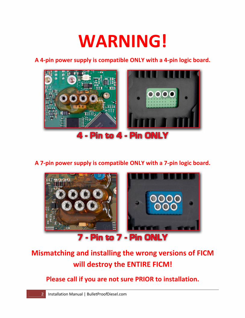
WARNING! A 4-pin power supply is compatible ONLY with a 4-pin logic board.
A 7-pin power supply is compatible ONLY with a 7-pin logic board.
Mismatching and installing the wrong versions of FICM
will destroy the ENTIRE FICM!
Please call if you are not sure PRIOR to installation.

3 Installation Manual | BulletProofDiesel.com
Thank you for purchasing the Bullet Proof Diesel Fuel Injection Control Module (FICM) power supply.
Please read and understand all of the instructions prior to beginning the replacement of your FICM
power supply. Call us if you have any questions.
The Original Equipment (OE) FICM power supply is part of the complete FICM assembly. The FICM
assembly consists of two circuit boards; the logic board and the power supply board, contained within a
(two piece) cast aluminum housing. This housing is mounted, in most cases, over the driver’s side engine
valve cover.
The logic circuit board is mounted to the side of the FICM assembly that also has the vehicle interface
wire harness connectors. All programming and logic functions of the FICM reside within the logic circuit
board. This part of the FICM assembly will remain with the vehicle, therefore no additional programming
of the FICM is needed to facilitate a proper repair.
There are two types of FICM logic boards; a 7-pin (or screws) and a 4-pin. To find out what version you
have, you must remove the two Torx #20 screws from the screw cover plate, and count the number of
Torx #10 screws found underneath.
The FICM power supply circuit board is located in the recessed half of the FICM assembly. The function
of this circuit board is to convert 12 volts DC into 48 volts DC. The 48 volts is what the logic circuit board
uses to actuate the fuel injectors.

4 Installation Manual | BulletProofDiesel.com
Fuel Injection Control Module (FICM) Install
Introduction
Bullet Proof Diesel offers two options for FICM power supply replacement; the 4-phase and the 6-phase.
Both versions have been designed to exceed OE specifications in both functionality and reliability. Both
versions include the all billet aluminum recessed power supply housing.
The 4-phase power supply is a heavy duty power supply for the direct replacement of the OE FICM
power supply. It is available in the 48 volt configuration only. It is offered as a high quality solution at a
lower price than the ultra-heavy duty 6-phase FICM.
The 6-phase power supply is the ultimate high performance FICM power supply. It comes preset at 48
volts, but can be set to 53 volts or 58 volts by the end user. While we have no information supporting
negative consequences of running higher than OE FICM voltages (other than setting a trouble code for
high FICM voltage), please note that selecting a higher voltage may have unforeseen consequences. Do
so at your own risk.
The design of our 4-phase and 6-phase circuits provide a cleaner, more stable current and voltage
output than the OE FICM power supply. The Bullet Proof FICM – even at 48 volts - has been shown to
increase fuel economy, eliminate injector sticking, improve cold drivability and cold weather starts. The
billet aluminum housing offers considerable gains in heat removal from the FICM over the OE cast
housing.
5 Installation Manual | BulletProofDiesel.com
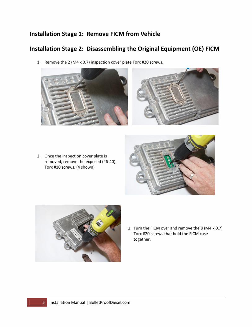
Installation Stage 1: Remove FICM from Vehicle
Installation Stage 2: Disassembling the Original Equipment (OE) FICM
1. Remove the 2 (M4 x 0.7) inspection cover plate Torx #20 screws.
2. Once the inspection cover plate is removed, remove the exposed (#6-40) Torx #10 screws. (4 shown)
3. Turn the FICM over and remove the 8 (M4 x 0.7) Torx #20 screws that hold the FICM case together.

6 Installation Manual | BulletProofDiesel.com
4. Once the screws have been removed, CAREFULLY pry the two halves apart:
5. Locate and remove the FICM gasket:
*Note: The gasket may be adhered to either side of the FICM case. You will resuse this gasket.
Installation Stage 3: Selecting the FICM Voltage (6-phase only)
*Note: The Bullet Proof Diesel FICM comes set at 48 volts. The following steps are only necessary if a 53 volt or 58 volt FICM is desired. Exceeding OE voltage may have unforeseen consequences. Do so at your own risk.
1. Locate the voltage selection chart on the FICM power supply board:

7 Installation Manual | BulletProofDiesel.com
2. Locate voltage selection wires:
3. Based on voltage selection
chart, clip appropriate wire for 53 or 58 volts.
Installation Stage 4: Assemble New FICM
1. Place gasket in new Bullet Proof Diesel FICM case. (6-phase FICM shown)
2. Place stock logic board on Bullet Proof Diesel power supply, and install the 8 (M4 x 0.7) Torx #20 screws. Tighten to 2 Nm (18 inch-pounds).
3. Turn FICM over and install the 4 (#6-40) Torx #10 screws. Tighten to 1 Nm (9 inch-pounds).
*Note: Do not over tighten.
Cut for 53V
Cut for 58V

8 Installation Manual | BulletProofDiesel.com
Installation Stage 5: Testing FICM Voltage
1. Re-install the FICM on vehicle. Make sure the electrical connections are firmly in place. 2. Using a digital volt ohm meter (DVOM), test the FICM output. This is done by measuring the
voltage at the moment the ignition key is turned on, but without cranking the engine, during the initial injector cycle. DO NOT SHORT CIRCUIT! Doing so will void the warranty.
*Note: If volt meter does not read the correct voltage, contact Bullet Proof Diesel before moving on to
the next step. The voltage specs are 48 volts ± 1 volt. On the 6-phase power supply, the voltage specs are ± 1 volt of the selected output voltage. Not all scan tools or data monitors will display actual FICM voltage. This manual method must be done prior to calling for tech support as it will be the first question we ask you.
Installation Stage 6: Finishing Installation 1. Install the inspection cover plate. Tighten to 2 Nm (18 inch-pounds).
2. Re-install all of the parts removed from the vehicle during the disassembly process. Do not start the vehicle until the re-assembly is complete.