Embed Size (px)
Citation preview
1
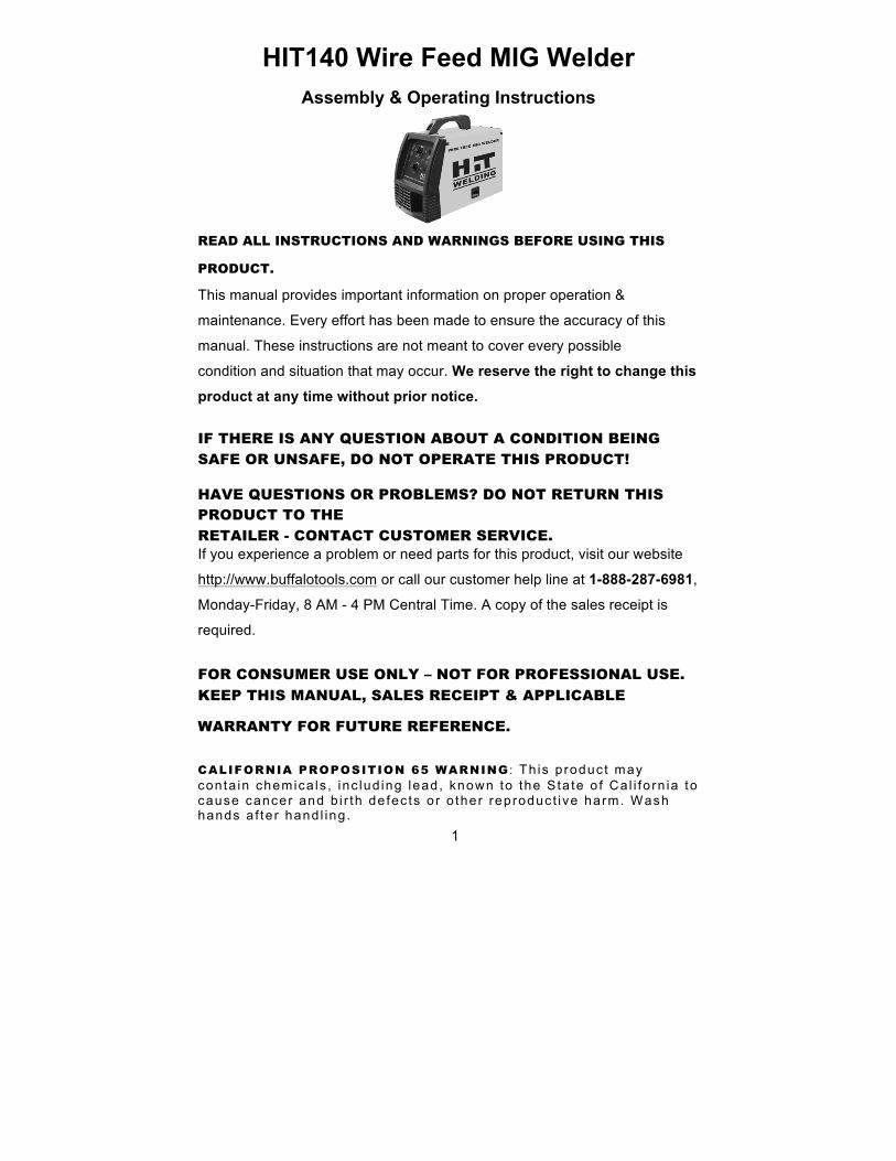
HIT140 Wire Feed MIG Welder Assembly & Operating Instructions
READ ALL INSTRUCTIONS AND WARNINGS BEFORE USING THIS
PRODUCT.
This manual provides important information on proper operation &
maintenance. Every effort has been made to ensure the accuracy of this
manual. These instructions are not meant to cover every possible
condition and situation that may occur. We reserve the right to change this
product at any time without prior notice.
IF THERE IS ANY QUESTION ABOUT A CONDITION BEING SAFE OR UNSAFE, DO NOT OPERATE THIS PRODUCT!
HAVE QUESTIONS OR PROBLEMS? DO NOT RETURN THIS PRODUCT TO THE RETAILER - CONTACT CUSTOMER SERVICE. If you experience a problem or need parts for this product, visit our website
http://www.buffalotools.com or call our customer help line at 1-888-287-6981,
Monday-Friday, 8 AM - 4 PM Central Time. A copy of the sales receipt is
required.
FOR CONSUMER USE ONLY – NOT FOR PROFESSIONAL USE. KEEP THIS MANUAL, SALES RECEIPT & APPLICABLE
WARRANTY FOR FUTURE REFERENCE.
CALIFORNIA PROPOSITION 65 WARNING : Th is p roduc t may conta in chemica ls , inc lud ing lead, known to the S ta te o f Ca l i fo rn ia to cause cancer and b i r th de fec ts o r o ther reproduct ive harm. Wash hands a f te r hand l ing .
2
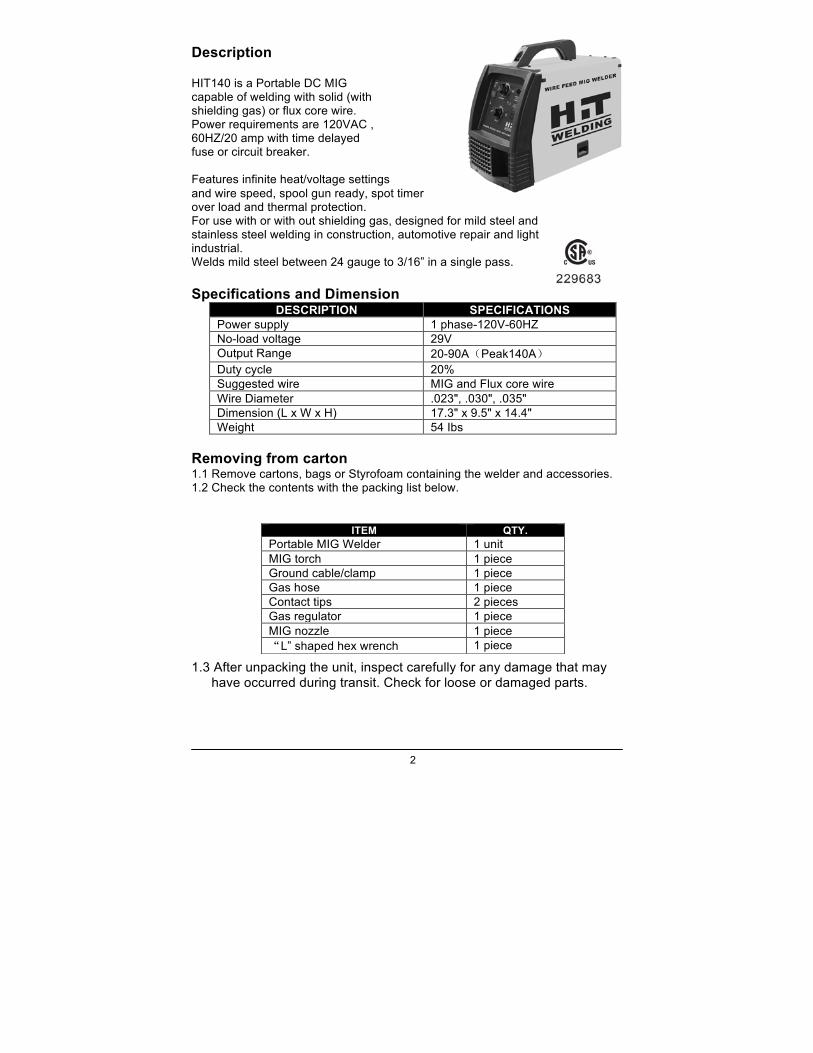
Description HIT140 is a Portable DC MIG capable of welding with solid (with shielding gas) or flux core wire. Power requirements are 120VAC , 60HZ/20 amp with time delayed fuse or circuit breaker. Features infinite heat/voltage settings and wire speed, spool gun ready, spot timer over load and thermal protection. For use with or with out shielding gas, designed for mild steel and stainless steel welding in construction, automotive repair and light industrial. Welds mild steel between 24 gauge to 3/16” in a single pass. Specifications and Dimension
DESCRIPTION SPECIFICATIONS Power supply 1 phase-120V-60HZ No-load voltage 29V Output Range 20-90A(Peak140A) Duty cycle 20% Suggested wire MIG and Flux core wire Wire Diameter .023", .030", .035" Dimension (L x W x H) 17.3" x 9.5" x 14.4" Weight 54 Ibs
Removing from carton 1.1 Remove cartons, bags or Styrofoam containing the welder and accessories. 1.2 Check the contents with the packing list below. 1.3 After unpacking the unit, inspect carefully for any damage that may
have occurred during transit. Check for loose or damaged parts.
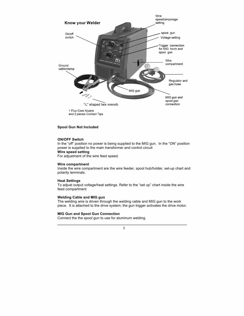
ITEM QTY. Portable MIG Welder 1 unit MIG torch 1 piece Ground cable/clamp 1 piece Gas hose 1 piece Contact tips 2 pieces Gas regulator 1 piece MIG nozzle 1 piece “L” shaped hex wrench 1 piece
3
Spool Gun Not Included ON/OFF Switch In the “off” position no power is being supplied to the MIG gun. In the “ON” position power is supplied to the main transformer and control circuit Wire speed setting For adjustment of the wire feed speed. Wire compartment Inside the wire compartment are the wire feeder, spool hub/holder, set-up chart and polarity terminals. Heat Settings To adjust output voltage/heat settings. Refer to the “set up” chart inside the wire feed compartment Welding Cable and MIG gun The welding wire is driven through the welding cable and MIG gun to the work piece. It is attached to the drive system; the gun trigger activates the drive motor. MIG Gun and Spool Gun Connection Connect the the spool gun to use for aluminum welding.
4
Ground Cable and Clamp The ground cable/clamp are attached to the work piece to complete the circuit, allowing the flow of current needed to weld. Thermal Indicator If the duty cycle of the welder is exceeded the internal temperature will exceed safe temperatures and the machine will shut down. The Thermal overload light will come on indicating this. Allow about 15 minutes for cool down before the light will go off and the temperature to fall into an allowable operating range. Power Cord The power cord connects the welder to the 120 volt power supply. Plug the 15 amp plug into a 120 volt/20 amp receptacle to supply power to the welder. General Safety Information
1.1 Your Welding Environment -Keep the environment you will be welding in free from flammable materials. -Always keep a fire extinguisher accessible to your welding environment. -Always have a qualified person install and operate this equipment. -Make sure the area is clean, dry and ventilated. Do not operate the welder in humid, wet or poorly ventilated areas. -Always have your welder maintained by a qualified technician in accordance with local, state and national codes. -Always be aware of your work environment. Be sure to keep other people, especially children, away from you while welding. -Keep harmful arc rays shielded from the view of others. -Mount the welder on a secure bench or cart that will keep the welder secure and prevent it from tipping over or falling. 1.2 Your Welder’s Condition -Check ground cable, power cord and welding cable to be sure the insulation is not damaged. Always replace or repair damaged components before using the welder. -Check all components to ensure they are clean and in good operating condition before use.
1.3 Use of Your Welder
Do not operate the welder if the output cable, electrode, MIG gun, wire or wire feed system is wet. Do not immerse them in water. These components and the welder must be completely dry before attempting to use them. -Follow the instructions in this manual. -Keep welder in the off position when not in use. -Connect ground lead as close to the area being welded as possible to ensure a good ground. -Do not allow any body part to come in contact with the welding wire if you are in contact with the material being welded, ground or electrode from another welder. -Do not weld if you are in an awkward position. Always have a secure stance while welding to prevent accidents. Wear a safety harness if working above ground. -Do not drape cables over or around your body. -Wear a full coverage helmet with appropriate shade (see ANSI Z87.1 safety standard) and safety glasses while welding. -Wear proper gloves and protective clothing to prevent your skin from being exposed to hot metals, UV and IR rays.
5
-Do not overuse or overheat your welder. Allow proper cooling time between duty cycles. -Keep hands and fingers away from moving parts and stay away from the drive rolls. -Do not point MIG gun at any body part of yourself or anyone else. -Always use this welder in the rated duty cycle to prevent excessive heat and failure. 1.4 Specific Areas of Danger, Caution or Warning
Electrical Shock
Electric arc welders can produce a shock that can cause injury or
death. Touching electrically live parts can cause fatal shocks and severe burns. While welding, all metal components connected to the wire are electrically hot. Poor ground connections are a hazard, so secure the ground lead before welding. -Wear dry protective apparel: coat, shirt, gloves and insulated footwear. -Insulate yourself from the work piece. Avoid contacting the work piece or ground. - Do not attempt to repair or maintain the welder while the power is on. -Inspect all cables and cords for any exposed wire and replace immediately if found. -Use only recommended replacement cables and cords. -Always attach ground clamp to the work piece or work table as close to the weld area as possible. -Do not touch the welding wire and the ground or grounded work piece at the same time. -Do not use a welder to thaw frozen pipes.
Fumes and Gases
-Fumes emitted from the welding process displace clean air and can result in
injury or death. -Do not breathe in fumes emitted by the welding process. Make sure your breathing air is clean and safe. -Work only in a well-ventilated area or use a ventilation device to remove welding fumes from the environment where you will be working. -Do not weld on coated materials (galvanized, cadmium plated or containing zinc, mercury or barium). They will emit harmful fumes that are dangerous to breathe. If necessary use a ventilator, respirator with air supply or remove the coating from the material in the weld area. -The fumes emitted from some metals when heated are extremely toxic. Refer to the material safety data sheet for the manufacturer’s instructions. -Do not weld near materials that will emit toxic fumes when heated. Vapors from cleaners, sprays and degreasers can be highly toxic when heated.
UV and IR Arc Rays
The welding arc produces ultraviolet (UV) and infrared (IR) rays
that can cause injury to your eyes and skin. Do not look at the welding arc without proper eye protection. -Always use a helmet that covers your full face from the neck to top of head and to the back of each ear. -Use a lens that meets ANSI standards and safety glasses. For welders under 160 Amps output, use a shade 10 lens; for above 160 Amps,
6
use a shade 12. Refer to the ANSI standard Z87.1 for more information. -Cover all bare skin areas exposed to the arc with protective clothing and shoes. Flame-retardant cloth or leather shirts, coats, pants or coveralls are available for protection. -Use screens or other barriers to protect other people from the arc rays emitted from your welding. -Warn people in your welding area when you are going to strike an arc so they can protect themselves.
Fire Hazards
Do not weld on containers or pipes that contain or have had flammable,
gaseous or liquid combustibles in them. Welding creates sparks and heat that can ignite flammable and explosive materials. -Do not operate any electric arc welder in areas where flammable or explosive materials are present. -Remove all flammable materials within 35 feet of the welding arc. If removal is not possible, tightly cover them with fireproof covers. -Take precautions to ensure that flying sparks do not cause fires or explosions in hidden areas, cracks or areas you cannot see. -Keep a fire extinguisher close in the case of fire. -Wear garments that are oil-free with no pockets or cuffs that will collect sparks. -Do not have on your person any items that are combustible, such as lighters or matches. -Keep work lead connected as close to the weld area as possible to prevent any unknown, unintended paths of electrical current from
causing electrical shock and fire hazards. -To prevent any unintended arcs, cut wire back to ¼" stick out after welding.
Hot Materials
Welded materials are hot and can cause severe burns if handled
improperly. -Do not touch welded materials with bare hands. -Do not touch MIG gun nozzle after welding until it has had time to cool down.
Sparks/Flying Debris
Welding creates hot sparks that can cause injury. Chipping slag off
welds creates flying debris. -Wear protective apparel at all times: ANSI-approved safety glasses or shield, welder’s hat and ear plugs to keep sparks out of ears and hair.
Electromagnetic Field
-Electromagnetic fields can interfere with various electrical and electronic
devices such as pacemakers. -Consult your doctor before using any electric arc welder or cutting device -Keep people with pacemakers away from your welding area when welding. -Do not wrap cable around your body while welding. -Wrap MIG gun and ground cable together whenever possible. -Keep MIG gun and ground cables on the same side of your body. Shielding Gas Cylinders Can Explode
High pressure cylinders can explode if damaged, so treat them carefully.
7
-Never expose cylinders to high heat, sparks, open flames, mechanical shocks or arcs. -Do not touch cylinder with MIG gun. -Do not weld on the cylinder -Always secure cylinder upright to a cart or stationary object. -Keep cylinders away from welding or electrical circuits. -Use the proper regulators, gas hose and fittings for the specific application. -Do not look into the valve when opening it. -Use protective cylinder cap whenever possible 1.5 Proper Care, Maintenance and Repair
-Always have power disconnected when working on internal components.
- Do not touch or handle PC board without being properly grounded with a wrist strap. Put PC board in static proof bag to move or ship.
-Do not put hands or fingers near moving parts such as drive rolls of fan
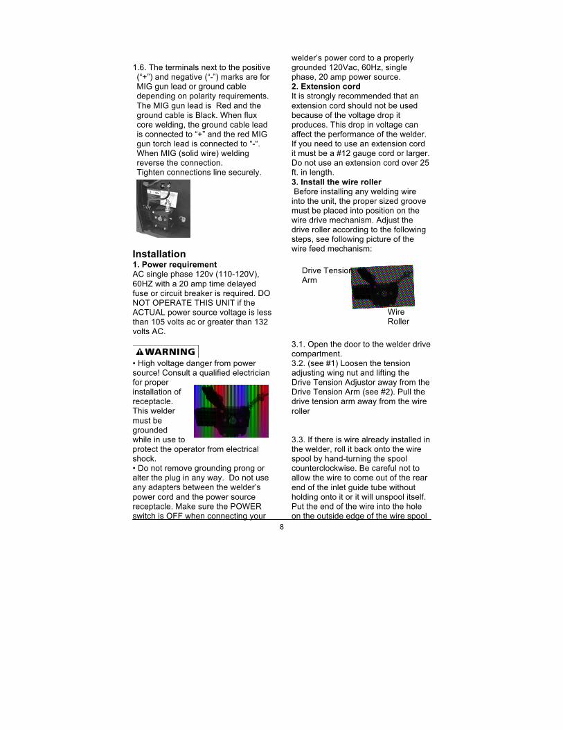
Assembly 1.1 MIG gun/torch attachment: Locate the set screw inside the front panel on the front of the drive system on the terminal block where the MIG gun will be inserted. Loosen set
screw. Insert MIG gun all the way into the receptacle and tighten set screw into the retaining groove on the end of the MIG gun
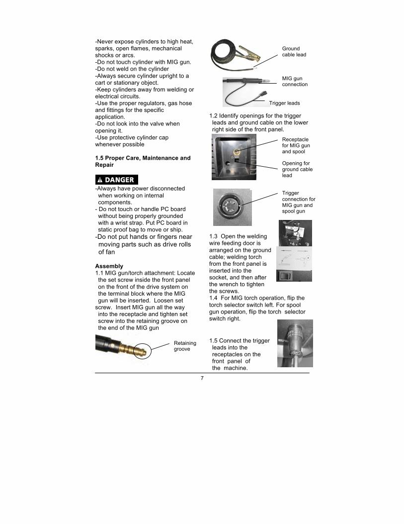
1.2 Identify openings for the trigger leads and ground cable on the lower right side of the front panel.
1.3 Open the welding wire feeding door is arranged on the ground cable; welding torch from the front panel is inserted into the socket, and then after the wrench to tighten the screws. 1.4 For MIG torch operation, flip the torch selector switch left. For spool gun operation, flip the torch selector switch right. 1.5 Connect the trigger leads into the receptacles on the front panel of the machine.
MIG gun connection
Trigger leads
Receptacle for MIG gun and spool gun
Trigger connection for MIG gun and spool gun
Opening for ground cable lead
Ground cable lead
Retaining groove
8
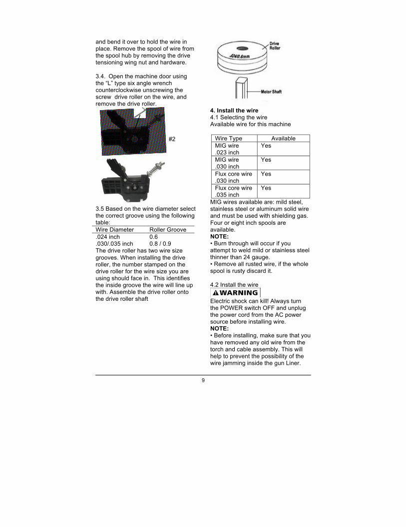
Wire Roller
Drive Tension Arm
1.6. The terminals next to the positive (“+”) and negative (“-”) marks are for MIG gun lead or ground cable depending on polarity requirements. The MIG gun lead is Red and the ground cable is Black. When flux core welding, the ground cable lead is connected to “+” and the red MIG gun torch lead is connected to “-“. When MIG (solid wire) welding reverse the connection. Tighten connections line securely.
Installation 1. Power requirement AC single phase 120v (110-120V), 60HZ with a 20 amp time delayed fuse or circuit breaker is required. DO NOT OPERATE THIS UNIT if the ACTUAL power source voltage is less than 105 volts ac or greater than 132 volts AC.
• High voltage danger from power source! Consult a qualified electrician for proper installation of receptacle. This welder must be grounded while in use to protect the operator from electrical shock. • Do not remove grounding prong or alter the plug in any way. Do not use any adapters between the welder’s power cord and the power source receptacle. Make sure the POWER switch is OFF when connecting your
welder’s power cord to a properly grounded 120Vac, 60Hz, single phase, 20 amp power source. 2. Extension cord It is strongly recommended that an extension cord should not be used because of the voltage drop it produces. This drop in voltage can affect the performance of the welder. If you need to use an extension cord it must be a #12 gauge cord or larger. Do not use an extension cord over 25 ft. in length. 3. Install the wire roller Before installing any welding wire into the unit, the proper sized groove must be placed into position on the wire drive mechanism. Adjust the drive roller according to the following steps, see following picture of the wire feed mechanism:
3.1. Open the door to the welder drive compartment. 3.2. (see #1) Loosen the tension adjusting wing nut and lifting the Drive Tension Adjustor away from the Drive Tension Arm (see #2). Pull the drive tension arm away from the wire roller 3.3. If there is wire already installed in the welder, roll it back onto the wire spool by hand-turning the spool counterclockwise. Be careful not to allow the wire to come out of the rear end of the inlet guide tube without holding onto it or it will unspool itself. Put the end of the wire into the hole on the outside edge of the wire spool
9
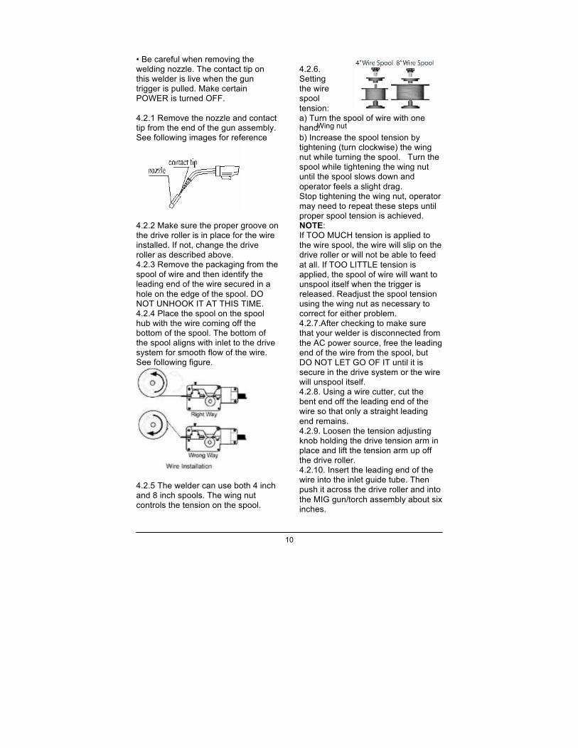
Drive tension adjustor
#2
and bend it over to hold the wire in place. Remove the spool of wire from the spool hub by removing the drive tensioning wing nut and hardware. 3.4. Open the machine door using the “L” type six angle wrench counterclockwise unscrewing the screw drive roller on the wire, and remove the drive roller.
3.5 Based on the wire diameter select the correct groove using the following table: Wire Diameter Roller Groove .024 inch 0.6 .030/.035 inch 0.8 / 0.9 The drive roller has two wire size grooves. When installing the drive roller, the number stamped on the drive roller for the wire size you are using should face in. This identifies the inside groove the wire will line up with. Assemble the drive roller onto the drive roller shaft
4. Install the wire 4.1 Selecting the wire Available wire for this machine
Wire Type Available MIG wire .023 inch
Yes
MIG wire .030 inch
Yes
Flux core wire .030 inch
Yes
Flux core wire .035 inch
Yes
MIG wires available are: mild steel, stainless steel or aluminum solid wire and must be used with shielding gas. Four or eight inch spools are available. NOTE: • Burn through will occur if you attempt to weld mild or stainless steel thinner than 24 gauge. • Remove all rusted wire, if the whole spool is rusty discard it. 4.2 Install the wire
Electric shock can kill! Always turn the POWER switch OFF and unplug the power cord from the AC power source before installing wire. NOTE: • Before installing, make sure that you have removed any old wire from the torch and cable assembly. This will help to prevent the possibility of the wire jamming inside the gun Liner.
10
• Be careful when removing the welding nozzle. The contact tip on this welder is live when the gun trigger is pulled. Make certain POWER is turned OFF. 4.2.1 Remove the nozzle and contact tip from the end of the gun assembly. See following images for reference
4.2.2 Make sure the proper groove on the drive roller is in place for the wire installed. If not, change the drive roller as described above. 4.2.3 Remove the packaging from the spool of wire and then identify the leading end of the wire secured in a hole on the edge of the spool. DO NOT UNHOOK IT AT THIS TIME. 4.2.4 Place the spool on the spool hub with the wire coming off the bottom of the spool. The bottom of the spool aligns with inlet to the drive system for smooth flow of the wire. See following figure.
4.2.5 The welder can use both 4 inch and 8 inch spools. The wing nut controls the tension on the spool.
4.2.6. Setting the wire spool tension: a) Turn the spool of wire with one hand. b) Increase the spool tension by tightening (turn clockwise) the wing nut while turning the spool. Turn the spool while tightening the wing nut until the spool slows down and operator feels a slight drag. Stop tightening the wing nut, operator may need to repeat these steps until proper spool tension is achieved. NOTE: If TOO MUCH tension is applied to the wire spool, the wire will slip on the drive roller or will not be able to feed at all. If TOO LITTLE tension is applied, the spool of wire will want to unspool itself when the trigger is released. Readjust the spool tension using the wing nut as necessary to correct for either problem. 4.2.7.After checking to make sure that your welder is disconnected from the AC power source, free the leading end of the wire from the spool, but DO NOT LET GO OF IT until it is secure in the drive system or the wire will unspool itself. 4.2.8. Using a wire cutter, cut the bent end off the leading end of the wire so that only a straight leading end remains. 4.2.9. Loosen the tension adjusting knob holding the drive tension arm in place and lift the tension arm up off the drive roller. 4.2.10. Insert the leading end of the wire into the inlet guide tube. Then push it across the drive roller and into the MIG gun/torch assembly about six inches.
Wing nut
8” wire spool
11
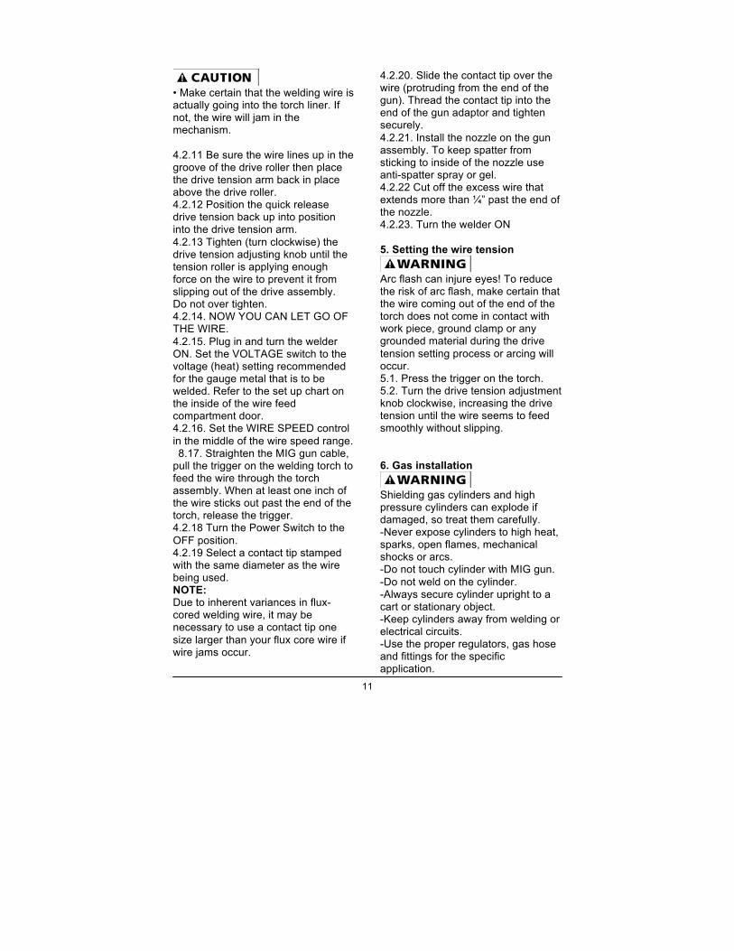
• Make certain that the welding wire is actually going into the torch liner. If not, the wire will jam in the mechanism. 4.2.11 Be sure the wire lines up in the groove of the drive roller then place the drive tension arm back in place above the drive roller. 4.2.12 Position the quick release drive tension back up into position into the drive tension arm. 4.2.13 Tighten (turn clockwise) the drive tension adjusting knob until the tension roller is applying enough force on the wire to prevent it from slipping out of the drive assembly. Do not over tighten. 4.2.14. NOW YOU CAN LET GO OF THE WIRE. 4.2.15. Plug in and turn the welder ON. Set the VOLTAGE switch to the voltage (heat) setting recommended for the gauge metal that is to be welded. Refer to the set up chart on the inside of the wire feed compartment door. 4.2.16. Set the WIRE SPEED control in the middle of the wire speed range. 8.17. Straighten the MIG gun cable,
pull the trigger on the welding torch to feed the wire through the torch assembly. When at least one inch of the wire sticks out past the end of the torch, release the trigger. 4.2.18 Turn the Power Switch to the OFF position. 4.2.19 Select a contact tip stamped with the same diameter as the wire being used. NOTE: Due to inherent variances in flux-cored welding wire, it may be necessary to use a contact tip one size larger than your flux core wire if wire jams occur.
4.2.20. Slide the contact tip over the wire (protruding from the end of the gun). Thread the contact tip into the end of the gun adaptor and tighten securely. 4.2.21. Install the nozzle on the gun assembly. To keep spatter from sticking to inside of the nozzle use anti-spatter spray or gel. 4.2.22 Cut off the excess wire that extends more than ¼” past the end of the nozzle. 4.2.23. Turn the welder ON 5. Setting the wire tension
Arc flash can injure eyes! To reduce the risk of arc flash, make certain that the wire coming out of the end of the torch does not come in contact with work piece, ground clamp or any grounded material during the drive tension setting process or arcing will occur. 5.1. Press the trigger on the torch. 5.2. Turn the drive tension adjustment knob clockwise, increasing the drive tension until the wire seems to feed smoothly without slipping. 6. Gas installation
Shielding gas cylinders and high pressure cylinders can explode if damaged, so treat them carefully. -Never expose cylinders to high heat, sparks, open flames, mechanical shocks or arcs. -Do not touch cylinder with MIG gun. -Do not weld on the cylinder. -Always secure cylinder upright to a cart or stationary object. -Keep cylinders away from welding or electrical circuits. -Use the proper regulators, gas hose and fittings for the specific application.
12
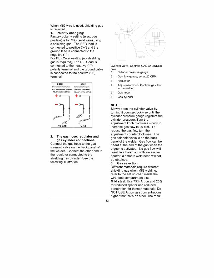
When MIG wire is used, shielding gas is required. 1. Polarity changing: Factory polarity setting (electrode positive) is for MIG (solid wire) using a shielding gas. The RED lead is connected to positive (“+”) and the ground lead is connected to the negative (“-”). For Flux Core welding (no shielding gas is required), The RED lead is connected to the negative (“-”) polarity terminal and the ground cable is connected to the positive (“+”) terminal.
2. The gas hose, regulator and
gas cylinder connections Connect the gas hose to the gas solenoid valve on the back panel of the welder. Connect the other end to the regulator connected to the shielding gas cylinder. See the following illustration.
321
7
Cylinder valve: Controls GAS CYLINDER flow. 1. Cylinder pressure gauge 2. Gas flow gauge, set at 20 CFM 3. Regulator 4. Adjustment knob: Controls gas flow
to the welder. 5. Gas hose 6. Gas cylinder
NOTE: Slowly open the cylinder valve by turning it counterclockwise until the cylinder pressure gauge registers the cylinder pressure. Turn the adjustment knob clockwise slowly to increase gas flow to 20 cfm. To reduce the gas flow turn the adjustment counterclockwise. The gas solenoid valve is on the back panel of the welder. Gas flow can be heard at the end of the gun when the trigger is activated. No gas flow will result in a harsh arc with excessive spatter, a smooth weld bead will not be obtained. 3. Gas selection. Different materials require different shielding gas when MIG welding, refer to the set up chart inside the wire feed compartment also. Mild steel: Use 75% Argon and 25% for reduced spatter and reduced penetration for thinner materials. Do NOT USE Argon gas concentrations higher than 75% on steel. The result
13
will be extremely poor penetration, porosity, and brittleness of weld. Mild Steel: Use CO2 for deeper penetration but increased spatter. Stainless steel: Use a mixed gas consisting of Helium, Argon and CO2. Aluminum or bronze: Use 100% Argon Operation
High voltage danger from power source! Consult a qualified electrician for proper installation of receptacle at the power source. This welder must be grounded while in use to protect the operator from electrical shock. If you are not sure if your outlet is properly grounded, have it checked by a qualified electrician. Do not cut off the grounding prong or alter the plug in any way and do not use any adapters between the welder’s power cord and the power source receptacle. Make sure the POWER switch is OFF then connect your welder’s power cord to a properly grounded 120 VAC(110v-120v), 60Hz, single phase, 20 amp power source. 1. Main control component Power switch - The power switch supplies electrical current to the welder. Whenever the power switch is in the ON position, the welding circuit is activated. ALWAYS turn the power switch to the OFF position and unplug the welder before performing any maintenance. Voltage selector - The voltage selector controls the welding voltage/heat. This unit has a five step voltage control. Refer to the label inside the welder side door for recommended voltage selector settings for your welding job. Wire speed control - The wire speed control adjusts the speed at which the
wire is fed out of the MIG gun. The wire speed needs to be closely matched (tuned-in) to the rate at which it is being melted off. Some things that affect wire speed selection are the type and diameter of the wire being used, the heat setting selected, and the welding position to be used. Note: The wire will feed faster without an arc. When an arc is being drawn, the wire speed will slow down. 2. Hold the MIG gun
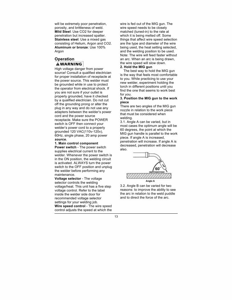
The best way to hold the MIG gun is the way that feels most comfortable to you. While practicing to use your new welder, experiment holding the torch in different positions until you find the one that seems to work best for you. 3. Position the MIG gun to the work piece There are two angles of the MIG gun nozzle in relation to the work piece that must be considered when welding. 3.1. Angle A can be varied, but in most cases the optimum angle will be 60 degrees, the point at which the MIG gun handle is parallel to the work piece. If angle A is increased, penetration will increase. If angle A is decreased, penetration will decrease also.
3.2. Angle B can be varied for two reasons: to improve the ability to see the arc in relation to the weld puddle and to direct the force of the arc.
14
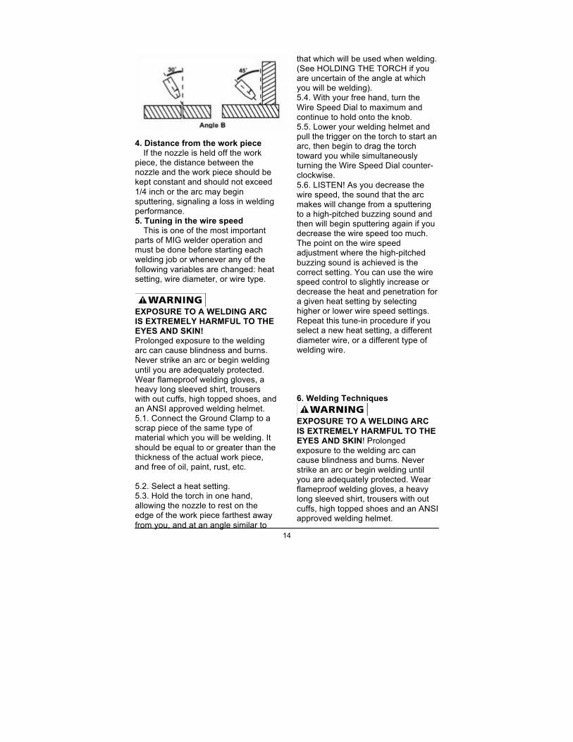
4. Distance from the work piece
If the nozzle is held off the work piece, the distance between the nozzle and the work piece should be kept constant and should not exceed 1/4 inch or the arc may begin sputtering, signaling a loss in welding performance. 5. Tuning in the wire speed
This is one of the most important parts of MIG welder operation and must be done before starting each welding job or whenever any of the following variables are changed: heat setting, wire diameter, or wire type.
EXPOSURE TO A WELDING ARC IS EXTREMELY HARMFUL TO THE EYES AND SKIN! Prolonged exposure to the welding arc can cause blindness and burns. Never strike an arc or begin welding until you are adequately protected. Wear flameproof welding gloves, a heavy long sleeved shirt, trousers with out cuffs, high topped shoes, and an ANSI approved welding helmet. 5.1. Connect the Ground Clamp to a scrap piece of the same type of material which you will be welding. It should be equal to or greater than the thickness of the actual work piece, and free of oil, paint, rust, etc. 5.2. Select a heat setting. 5.3. Hold the torch in one hand, allowing the nozzle to rest on the edge of the work piece farthest away from you, and at an angle similar to
that which will be used when welding. (See HOLDING THE TORCH if you are uncertain of the angle at which you will be welding). 5.4. With your free hand, turn the Wire Speed Dial to maximum and continue to hold onto the knob. 5.5. Lower your welding helmet and pull the trigger on the torch to start an arc, then begin to drag the torch toward you while simultaneously turning the Wire Speed Dial counter-clockwise. 5.6. LISTEN! As you decrease the wire speed, the sound that the arc makes will change from a sputtering to a high-pitched buzzing sound and then will begin sputtering again if you decrease the wire speed too much. The point on the wire speed adjustment where the high-pitched buzzing sound is achieved is the correct setting. You can use the wire speed control to slightly increase or decrease the heat and penetration for a given heat setting by selecting higher or lower wire speed settings. Repeat this tune-in procedure if you select a new heat setting, a different diameter wire, or a different type of welding wire. 6. Welding Techniques
EXPOSURE TO A WELDING ARC IS EXTREMELY HARMFUL TO THE EYES AND SKIN! Prolonged exposure to the welding arc can cause blindness and burns. Never strike an arc or begin welding until you are adequately protected. Wear flameproof welding gloves, a heavy long sleeved shirt, trousers with out cuffs, high topped shoes and an ANSI approved welding helmet.
15
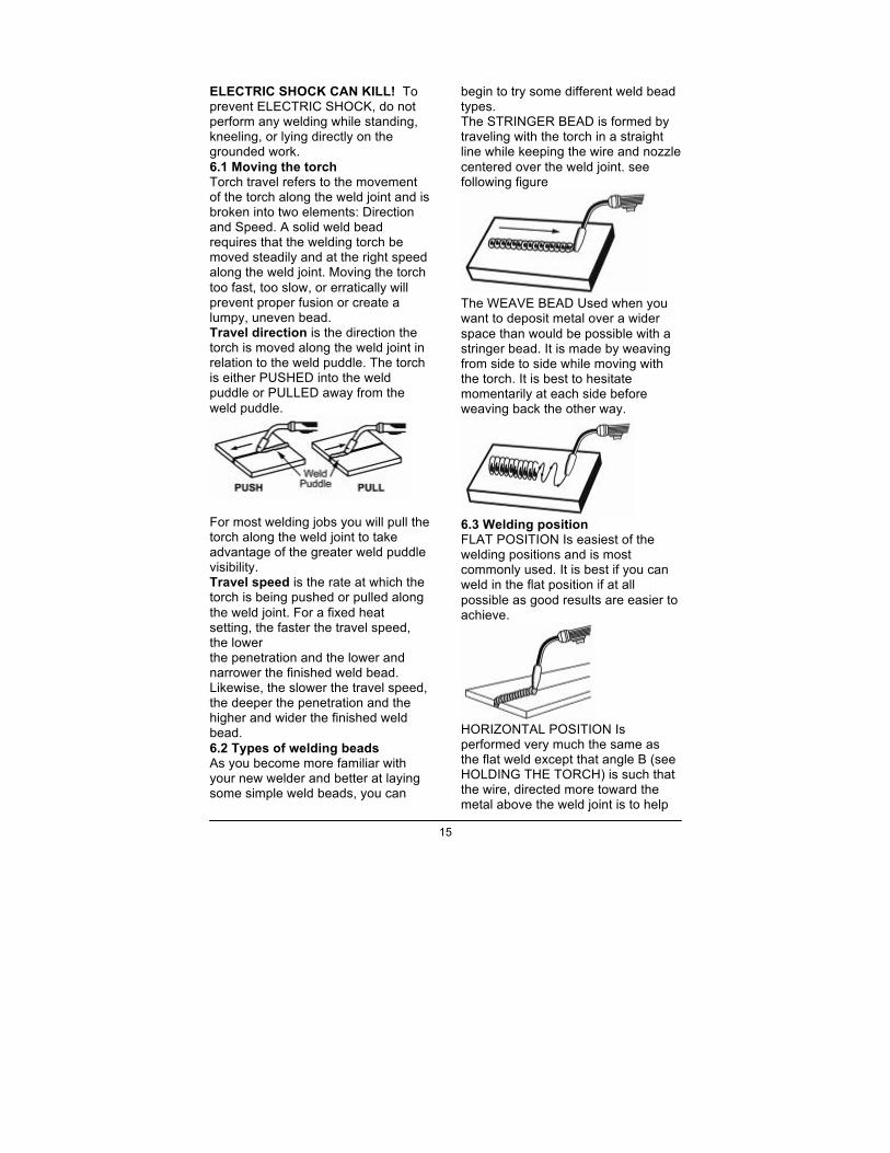
ELECTRIC SHOCK CAN KILL! To prevent ELECTRIC SHOCK, do not perform any welding while standing, kneeling, or lying directly on the grounded work. 6.1 Moving the torch Torch travel refers to the movement of the torch along the weld joint and is broken into two elements: Direction and Speed. A solid weld bead requires that the welding torch be moved steadily and at the right speed along the weld joint. Moving the torch too fast, too slow, or erratically will prevent proper fusion or create a lumpy, uneven bead. Travel direction is the direction the torch is moved along the weld joint in relation to the weld puddle. The torch is either PUSHED into the weld puddle or PULLED away from the weld puddle.
For most welding jobs you will pull the torch along the weld joint to take advantage of the greater weld puddle visibility. Travel speed is the rate at which the torch is being pushed or pulled along the weld joint. For a fixed heat setting, the faster the travel speed, the lower the penetration and the lower and narrower the finished weld bead. Likewise, the slower the travel speed, the deeper the penetration and the higher and wider the finished weld bead. 6.2 Types of welding beads As you become more familiar with your new welder and better at laying some simple weld beads, you can
begin to try some different weld bead types. The STRINGER BEAD is formed by traveling with the torch in a straight line while keeping the wire and nozzle centered over the weld joint. see following figure
The WEAVE BEAD Used when you want to deposit metal over a wider space than would be possible with a stringer bead. It is made by weaving from side to side while moving with the torch. It is best to hesitate momentarily at each side before weaving back the other way.
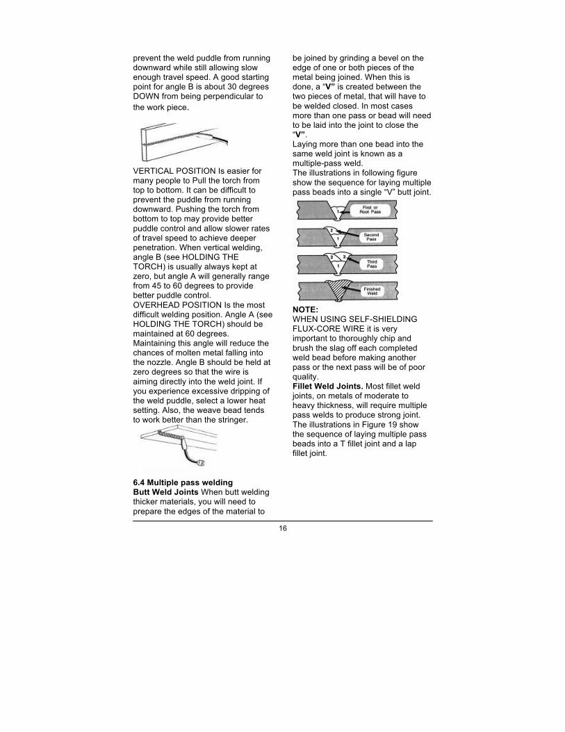
6.3 Welding position FLAT POSITION Is easiest of the welding positions and is most commonly used. It is best if you can weld in the flat position if at all possible as good results are easier to achieve.
HORIZONTAL POSITION Is performed very much the same as the flat weld except that angle B (see HOLDING THE TORCH) is such that the wire, directed more toward the metal above the weld joint is to help
16
prevent the weld puddle from running downward while still allowing slow enough travel speed. A good starting point for angle B is about 30 degrees DOWN from being perpendicular to the work piece.
VERTICAL POSITION Is easier for many people to Pull the torch from top to bottom. It can be difficult to prevent the puddle from running downward. Pushing the torch from bottom to top may provide better puddle control and allow slower rates of travel speed to achieve deeper penetration. When vertical welding, angle B (see HOLDING THE TORCH) is usually always kept at zero, but angle A will generally range from 45 to 60 degrees to provide better puddle control. OVERHEAD POSITION Is the most difficult welding position. Angle A (see HOLDING THE TORCH) should be maintained at 60 degrees. Maintaining this angle will reduce the chances of molten metal falling into the nozzle. Angle B should be held at zero degrees so that the wire is aiming directly into the weld joint. If you experience excessive dripping of the weld puddle, select a lower heat setting. Also, the weave bead tends to work better than the stringer.
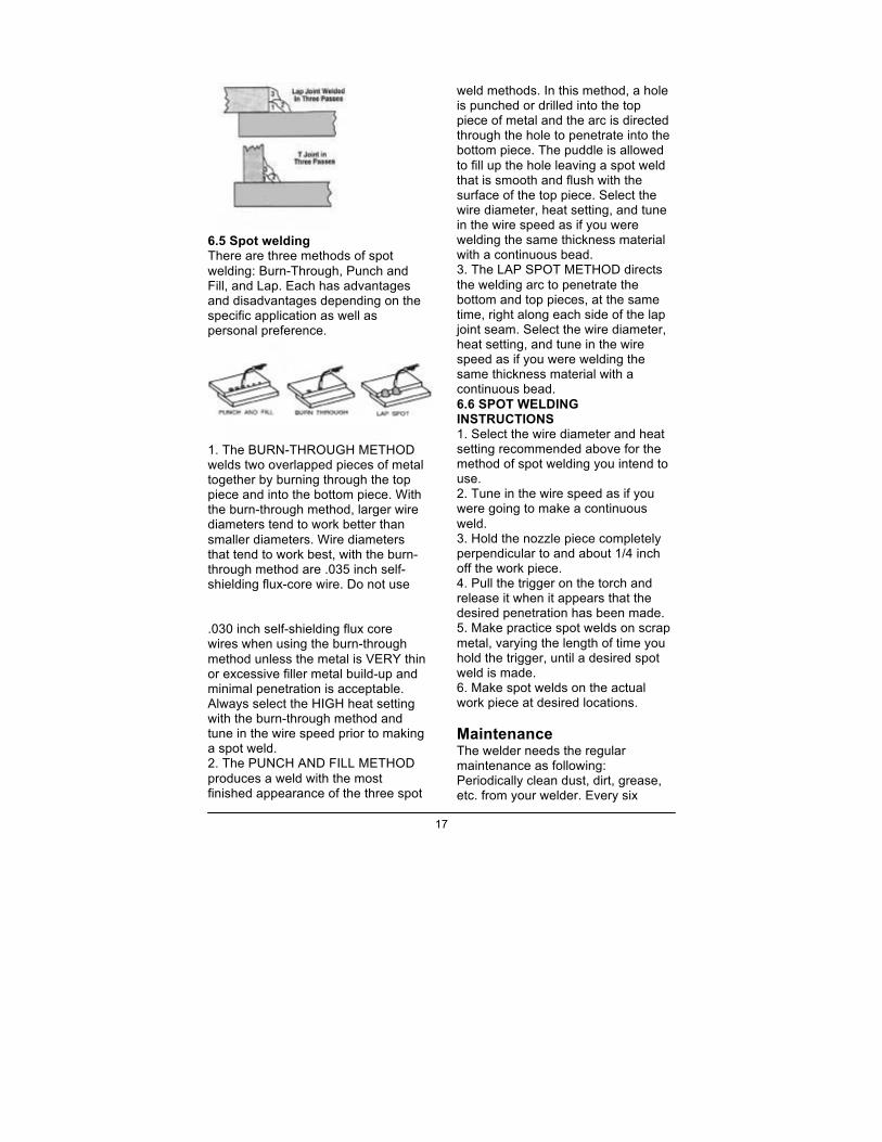
6.4 Multiple pass welding Butt Weld Joints When butt welding thicker materials, you will need to prepare the edges of the material to
be joined by grinding a bevel on the edge of one or both pieces of the metal being joined. When this is done, a “V” is created between the two pieces of metal, that will have to be welded closed. In most cases more than one pass or bead will need to be laid into the joint to close the “V”. Laying more than one bead into the same weld joint is known as a multiple-pass weld. The illustrations in following figure show the sequence for laying multiple pass beads into a single “V” butt joint.
NOTE: WHEN USING SELF-SHIELDING FLUX-CORE WIRE it is very important to thoroughly chip and brush the slag off each completed weld bead before making another pass or the next pass will be of poor quality. Fillet Weld Joints. Most fillet weld joints, on metals of moderate to heavy thickness, will require multiple pass welds to produce strong joint. The illustrations in Figure 19 show the sequence of laying multiple pass beads into a T fillet joint and a lap fillet joint.
17
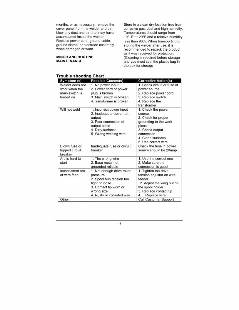
6.5 Spot welding There are three methods of spot welding: Burn-Through, Punch and Fill, and Lap. Each has advantages and disadvantages depending on the specific application as well as personal preference.
1. The BURN-THROUGH METHOD welds two overlapped pieces of metal together by burning through the top piece and into the bottom piece. With the burn-through method, larger wire diameters tend to work better than smaller diameters. Wire diameters that tend to work best, with the burn-through method are .035 inch self-shielding flux-core wire. Do not use .030 inch self-shielding flux core wires when using the burn-through method unless the metal is VERY thin or excessive filler metal build-up and minimal penetration is acceptable. Always select the HIGH heat setting with the burn-through method and tune in the wire speed prior to making a spot weld. 2. The PUNCH AND FILL METHOD produces a weld with the most finished appearance of the three spot
weld methods. In this method, a hole is punched or drilled into the top piece of metal and the arc is directed through the hole to penetrate into the bottom piece. The puddle is allowed to fill up the hole leaving a spot weld that is smooth and flush with the surface of the top piece. Select the wire diameter, heat setting, and tune in the wire speed as if you were welding the same thickness material with a continuous bead. 3. The LAP SPOT METHOD directs the welding arc to penetrate the bottom and top pieces, at the same time, right along each side of the lap joint seam. Select the wire diameter, heat setting, and tune in the wire speed as if you were welding the same thickness material with a continuous bead. 6.6 SPOT WELDING INSTRUCTIONS 1. Select the wire diameter and heat setting recommended above for the method of spot welding you intend to use. 2. Tune in the wire speed as if you were going to make a continuous weld. 3. Hold the nozzle piece completely perpendicular to and about 1/4 inch off the work piece. 4. Pull the trigger on the torch and release it when it appears that the desired penetration has been made. 5. Make practice spot welds on scrap metal, varying the length of time you hold the trigger, until a desired spot weld is made. 6. Make spot welds on the actual work piece at desired locations. Maintenance The welder needs the regular maintenance as following: Periodically clean dust, dirt, grease, etc. from your welder. Every six
18
months, or as necessary, remove the cover panel from the welder and air-blow any dust and dirt that may have accumulated inside the welder. Replace power cord, ground cable, ground clamp, or electrode assembly when damaged or worn. MINOR AND ROUTINE MAINTENANCE
Store in a clean dry location free from corrosive gas, dust and high humidity. Temperatures should range from 10°F–120°F and a relative humidity less than 90%. When transporting or storing the welder after use, it is recommended to repack the product as it was received for protection. (Cleaning is required before storage and you must seal the plastic bag in the box for storage
Trouble shooting Chart
Symptom (s) Possible Causes(s) Corrective Action(s) Welder does not work when the main switch is turned on
1. No power input 2. Power cord or power plug is broken 3. Main switch is broken 4.Transformer is broken
1. Check circuit or fuse of power source 2. Replace power cord 3. Replace switch 4. Replace the transformer
Will not weld
1. Incorrect power input 2. Inadequate current at output 3. Poor connection of output cable 4. Dirty surfaces 5. Wrong welding wire
1. Check the power source 2. Check for proper grounding to the work piece. 3. Check output connection 4. Clean surfaces 5. Use correct wire
Blown fuse or tripped circuit breaker
Inadequate fuse or circuit breaker
Check the fuse in power source should be 20amp
Arc is hard to start
1. The wrong wire 2. Base metal not grounded reliable
1. Use the correct one 2. Make sure the connection is good
Inconsistent arc or wire feed
1. Not enough drive roller pressure 2. Spool hub tension too tight or loose 3. Contact tip worn or wrong size 4. Rusty or corroded wire
1. Tighten the drive tension adjustor on wire feeder 2. Adjust the wing nut on
the spool holder 3. Replace contact tip 4. Replace wire.
Other Call Customer Support
19
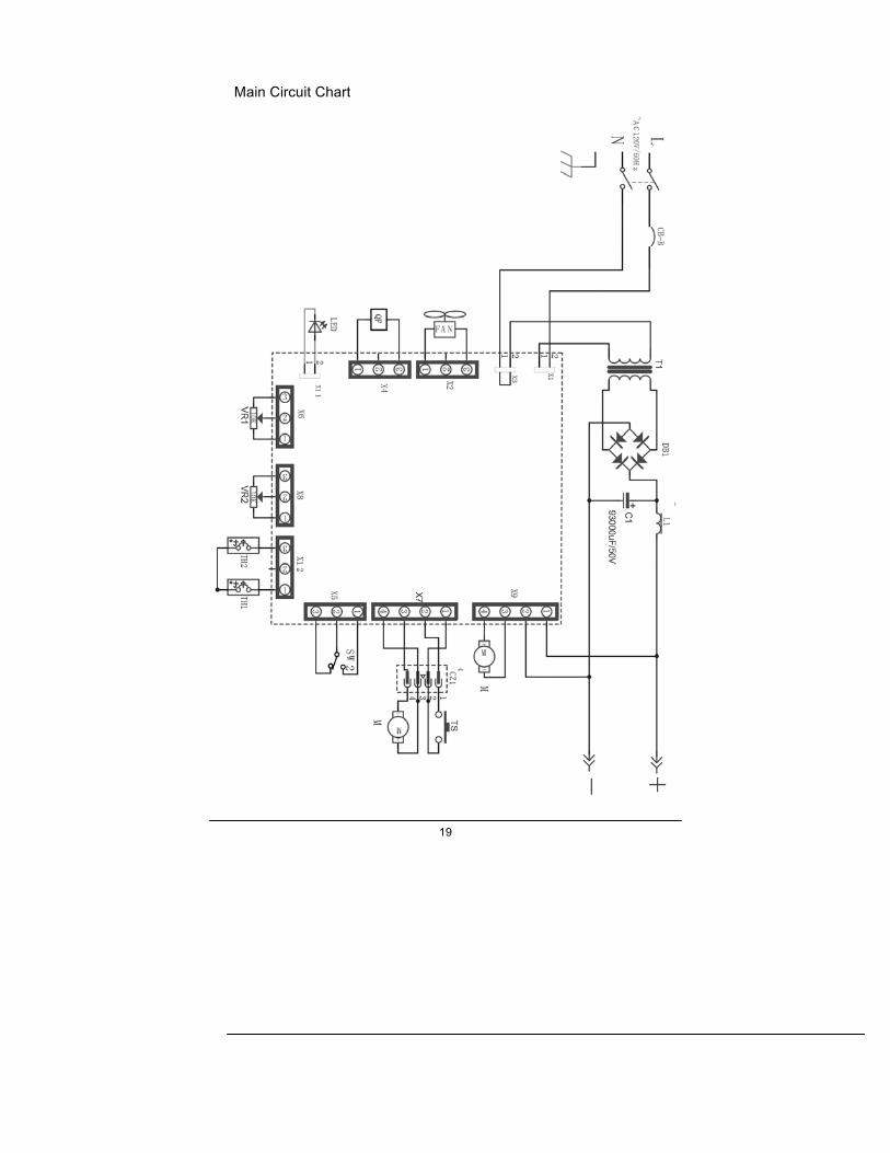
Main Circuit Chart
20