Embed Size (px)
Citation preview

OWNERS MANUALAssembly, Operating
Instructions and Parts List FOR THE FOLLOWING MODELS:
3025manual rev 122210
™
SA320120H3SA320120H346
SA320240H3SA320240H346
SA325120H3SA325120H346
SA325240H3SA325240H346
SA330120H3SA330120H346
SA330240H3SA330240H346

10. Never reset pressure switch or safety valves.
11. Never store flammable liquids or gases in the vicinity of the compressor or compressor starting equipment.
12. SHUTOFF VALVES ARE NOT TO BE INSTALLED IN THE DISCHARGE LINE BETWEEN THE COMPRESSOR AND THE RECEIVER UNLESS A SAFETY VALVE, WITH ADEQUATE FLOW CAPACITY AND PRES- SURE SETTING, IS LOCATED BETWEEN SHUTOFF VALVE AND THE COMPRESSOR.
13. When compressor is used for spraying: Do not spray in vicinity of open flame or other surfaces of ignition.
14. Do not smoke when spraying paint, insecticides, or other toxic or flammable substances.
15. To avoid spontaneous combustion, discard waste rags into approved metal waste cans.
16. Do not spray in confined spaces.
17. Use face mask when spraying.
18. Always direct paint or sprayed material away from compressor and locate compressor to minimize paint overspray accumulation on compressor or sprayer parts.
19. When using cleaning solvent, follow the instruc- tions provided by the solvent manufacturer.
When using air compressors and compressed air accessories, basic safety rules and precautions should always be followed including the following:
1. Read all instructions fully.
2. Wiring, starters, breakers and other related electrical equipment should conform to electri- cal codes.
3. Shut off main power and release all pressure from the unit and set pressure regulator to zero pressure before removing or adding parts or attachments and before cleaning compressor.
4. Do not operate any compressor with damaged wiring or after the compressor or air handling parts have been dropped or damaged, deterio- ration, weakness or leakage. Do not use them if deficiency is found. Withdraw from service and repair or discard such parts.
5. Regularly inspect hose and load handling fittings for signs of damage, deterioration, weakness or leakage. Do not use them if deficiency is found. Withdraw from service and repair or discard such parts.
6. Never use air pressurized accessories or parts in the air system not suitable for the maximum air pressure involved. This is dangerous. Be sure maximum pressure specified by the manu- facturer is well above the working pressure of your compressor.
7. Keep clear of compressor. It will become extremely hot. Moving parts should be avoided. Do not operate without belt guard.
8. Keep pressure relief devices free from paint or other accumulation. 9. Drain tank daily to prevent rust formation in the tank.
SAFETY INSTRUCTIONS

Four Cylinder-Two StageBore 5-12-3 In., Stroke 5 In.
INTRODUCTION In order to receive maximum performance the follow-ing instructions should be carefully read and all points regarding installation and operation of the unit should be noted and observed.
This compressor may be operated with a 15, 20 or 25 HP Motor. Refer to page 18 for performance data.
INSTALLATION INSTRUCTIONS
1. INSPECTIONCheck for possible damage in transit and see that the pulley turns freely by hand. Report any damage to delivering carrier at once.
2. LOCATIONSelect a clean, dry, and light location. In cold climates the compressor should be installed in a heated build-ing. Insulate cold water or other low temperature pipes that pass overhead to avoid the possible collection and dripping of condensate onto the compressor and motor which could cause rusting and/or motor shorting. Do not install the compressor in a boiler room, paint spray room or area where sandblasting is carried on. If that air in the area where the compressor intake should be piped to the outside. This intake pipe should be increased one pipe size for every twenty (20) feet of run and the intake filters should be installed at the end of the pipes with a hood to protect them from the ele-ments.
If the compressor has to be located where the motor will be exposed to appreciable quantities of water, oil, dirt, acid or alkaline fumes the motor must be special construction to avoid rapid deterioration.Bolt the unit securely and evenly to a level base. Unless base is exactly level, shims will probably be required. Any space between base and foot should be shinned rather than drawing foot down thus placing strain on unit. When unit is properly shimmed vibration will be at a minimum.
Allow sufficient space around compressor so that it is accessible from all sides for maintenance. Mount unit with pulley side toward the wall, but at least eight (8) inches from it.
3. POWER SUPPLY AND WIRINGBe sure that your power supply and internal wiring are adequate and that the available frequency and voltage correspond to that on the motor nameplate. A 230 volt motor will rarely work satisfactorily on a nominal 208 volt system. Even if the actual voltage is up to 208 volts the 10 to 12 volt drop during starting period (this is an average but not a high figure for commercial buildings), may cause the motor to labor and blow fuses or heater elements. Do not accept the nominal figure for line volt-age, but rather measure it with a voltmeter during a period of maximum power demand.
If the power is “Network” distributed with 208 volts entering the building, order a 208 volt motor. If the start-ing voltage is much less than 90% of the motor name-plate voltage, the motor cannot be expected to start and the interior building wiring must be corrected.
The wiring should be done by a licensed electrician who is familiar with the requirements of the National Board of fire Underwriters and of the local inspectors. Consult your local electrical contractor and electrical codes for recommended wire sizes. Refer to pages 19 & 21 typi-cal wiring diagrams.
4. STARTINGA. This Compressor may be shipped without oil in the crankcase. Before starting, fill crankcase to the high level mark on the oil fill hole (approximately six (6) quarts) with a good grade of compressor oil meeting the following specifications.
AMBIENT OR VISCOSITY FLASH POUR ROOM TEMP. AT 100F POINT POINT ˚F S.S.U. ˚F (Min.) ˚F (Min.) 55 to 120 490 to 600 430 +20 32 to 55 290 to 350 390 +5 0 to 32 160 to 230 350 -10 Above 120 or below 0 CONSULT MANUFACTURER
AMBIENT OR CARBON ROOM TEMP. RESIDUE PREFERRED OF %(Max.) BASE
55 to 120 .15 430 32 to 55 .10 390 0 to 32 .05 350
Above 120 or below 0 CONSULT MANUFACTURER

NOTE: Foroperationindamporhumidlocations additionofrustinhibitorisrecomended.
B. Turn compressor over a revolutions by hand to make sure that everything is free and in running condition.C. Check tension of the belts (See Paragraph 7).D. Remove tools, rags, and any other objects from the vicinity of the compressor.E. Never put hands on the belts of idle units, unless main motor switch is off.F. Note direction of arrow on flywheel and be sure direction of rotation is correct when machine is started. Correct direction is counter-clockwise when standing facing the flywheel. Air should be drawn through inter-cooler onto the cylinders for maximum cooling.
5. PIPINGCompAir Kellog compressors are equally equipped with intake filters requiring no piping. If it is necessary to pipe intake the outdoors, see paragraph 2, “Location”.Discharge piping should be as short and as straight as possible and as large or larger than the connection to the compressor.
6. STANDARD DUAL CONTROLThe standard dual control for CompAir Kellog model 462 includes a pressure switch, 3-way solenoid valve with slow bleed orifice and electric 3-way selector switch. By turning the selector switch the compressor will automatically operate as either a start-stop or con-tinuousrunning unit. The switch also provides a control circuit off switch. (Refer to Pages 20 & 21 for compo-nents and wiringof the Dual Control System.)With the selector switch (5) in the start-stop position both contacts of the operating pressure switch (2) open when air receiver pressure reaches the cut-out setting of the operating pressure switch. The magnetic starter coil and 3-way solenoid valve coil (12) is deenergized and the compressor stops in an unloaded condition since ports 3 and 1 of the 3-way solenoid valve are common and air receiver pressure in introduced to the suction unloaders which in turn, opens the suction valves. When air receiver reaches the the cut-in set-ting of the operating pressure switch (2) both contacts close and the magnetic starter coil and 3-way solenoid valve coil are energized and the compressor motor starts. Ports 1 and 2 of the 3-way solenoidvalve are now common and the air trapped between the 3-way solenoid valve coil are energized and the compressor motor starts. Ports 1 and 2 of the 3-way solenoid valve are now now common and and the air trapped is bled off automatically and slowly enough through orifice
(10) to allow the motor to come up to speed with the compressor compeletly unloaded. This d elay period is approximately 4 seconds. After all air has been bled from the suction unloader line, the suction valves close and thecompression of air resumes.With the selector switch in the constant run position one set of contactsin the operating pressure switch (2) which normally deenergize the magnetic starter holding coil are bypassed. When air receiver pressure reaches the cut-out setting of the operating pressure switch (2) only the 3-way solenoid valve coil is denergize-dand unloading of the compressor suction valves and resumption of air compression is as described above.If for any reason, power to the compressor is interrupt-ed with pressure in the air receiver the compressor will stop in an unloaded condition.This is not true with pilot operated constant speed con-trol as noted in Section 21.This dual control system is required to eliminate starting problems. The centrifugal unloader DOES NOT normal-ly provide a sufficiently long unloaded period to enable the compressor to start.
IMPORTANTStandard 3-way solenoid valve coil voltages are listed on Page 20. This voltage must be compatible with the system control voltage.
7. BELT ADJUSTMENTWhen installing new belts it is necessary that the motor bolts be loosened and the motor be moved toward the compressor. The new belts can then be installed with-out damage or strain. As belts will stretch it is recom-mended that all belts be changed at the same time.When belt tension is adjusted properly the belts can be depressed, at a point midway between the motor pulleyand the flywheel, approxiamately one half of an inch. Loose belts will slip on the motor pulley and cause undue heating and wear. A belt that is too tight will overload the bearings. Adjustments can be made by sliding the motor along its base.
8. DAILY CARECheck oil level in crankcase and if necessary, add suf-ficient oil to being level, or slightly above the center of the visual oil guage.Drain oil receiver, drop legs, etc.Stop, look, and listen a moment for any unusual noise, failure to compress, overheating, vibration, or belt slip-
CAUTION
A. Never install a shut-off valve, such as a globe or gate valve, between the compressor discharge opening and the receiver unless a safety valve is installed in the line between this valve and the com-pressor.
WARNING
Prior to performing any maintenance on this compressor,disconnect all powerat the circuit breaker, lockout, and completely depressurize the unit. Failure to do this may cause severe injury or death.
OPERATION AND CARE
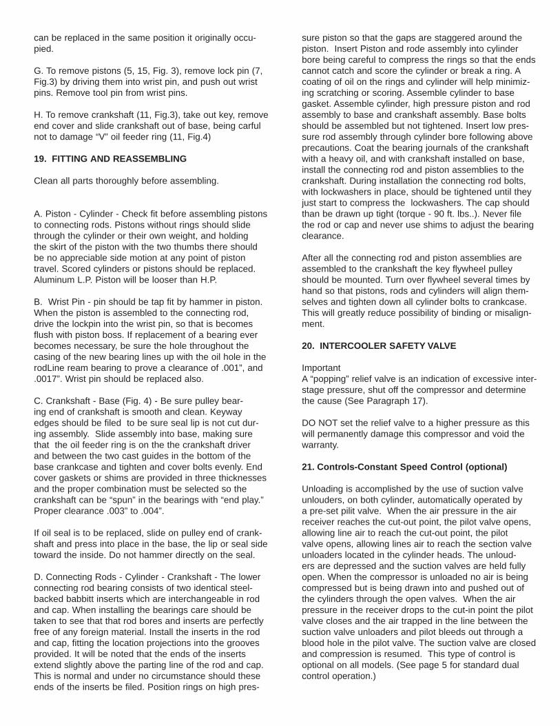
page and correct before damage of a serious nature can develop.
9. MONTHLY CARE (Also see Par. 10 For Valve Care)Check and tighten all bolts, as required. Check air con-nections and joints for leaks. Check all unloading lines for air leaks. Air leaks in the unloading lines will cause the unloaders to chatter as well as cause short cycling. If main air supply is not clean of oil and moisture-free a strainer mounted ahead of the pilot valve is recom-mended.Check “V” belts for any possible misalignment and tight-ness. See paragraph 7 for adjustment.(Refer to page 18 for Bolt Torque Chart.)
10. VALVESValves are generally considered to be maintenancce items and require care by the user. They are the most important part of the compressor and the importance of proper care and maintenace cannot be over-empha-sized.
All valves should be removed from the cylinder head at the end end of the first two or three months of operation and examined for cleanliness and carbon formation. Clean with safety solvent and blow off with compressor air. Depending on what is found at this inspection, the next inspection should not be more than 4 to 6 months later. These 2 inspections will guide you in scheduling periodic cleaning times which will pay off many times over in providing trouble free service and down time.
11. SLOW PUMP OR INSUFFICIENT PRESSURE CAN BE CAUSED BY:
A. A clogged inlet filter - (Disassemble and clean thor-oughly)
B. Leaks in air lines, valves, fittings etc. - (Locate using soapy water if necessary; replace or tighten threaded parts.)
C. Compressor too small for equipment being oper-ated. - (Check air requirements and add to compressor capacity. Consult dealer.)
D. Leaking head valves - (Remove and hold- down cov-ers (15,25, Fig. 2) and remove valves for examination. Repair or replac faulty valves). Valves can be removed from the head by tappimng valve screw with the ham-mer handle or piece of wood, to loosen valve from head, before lifting valve.
Clean all parts thoroughly. Valves and seats must be flat and smooth and sometimes can be resurfaced by rubbing the fine (No. 400) emery cloth held on a smooth flat surface. Badly worn parts, including springswhich lose tension after considerable use should be replaced. Reassemble valve parts in sequence indicated in Fig. 2. Examine valve gaskets carefully and replace if doubtful of condition. Be careful that nothing falls into the cylin-der that could get caught between top of piston and cyl-inder head. Before reassembling valve look into cylinder through valve opening while turning flywheel by hand.
E. Sticking Pilot Valve or solenoid valve - Dirt in line, or defective pilot valve or defective solenoid valve, could hold valve open alowing unloading fingers to keep inlet valves open. Sometimes tapping the pilot valve or sole-noid valve, or working hand lever will allow pilot valve to resume normal operation. If not, remove, clean or replace.
12. EXCESSIVE OIL CONSUMPTION
“Oil Pumping” usually results from using the wrong type or an inferior grade of oil. Replacing worn or stuck piston rings will help correct this condition, but contrary to popular belief, worn rings do not affect pumping effeciency apreciably.
Piston rings can be replaced by removing cylinder while the heads are off. Remove oil rings (4, 16, Fig. 3) and clean grooves in piston.
The oil rings provided are of the latest design and are the same as furnished on the new automobile engines. They are of of three-piece construction with two chrome-plated rails and an expander and an expander ring. Some new units may pump a slight amount of oil for a period of time but as the chrome-plated rails seat to the cylinder walls this will gradually diminish. Should excessive oil consumption continue, the cylinders should be checked for scoring and the oil ring checked for proper assembly. The two ends of the expander ring are colored with paint for identification and when prop-erly assembled should be butted, not overlapped.
A coating of clean oil should be placed on the rings and the inside of the cylinders for ease of assembly and to minimize possibility of scoring cylinder. See paragraph 19 for reassembly procedure.
13. NOISY OPERATION CAN BE CAUSED BY
A. Loose parts - external - (Tighten loose boltsparticu-larly the flywheel pulley to the crankshaft.)
B. Foreign matter such as carbon, metal chips, etc. on pistons striking head at top of stroke (Remove head and clean.C. Piston extending above cylinder at top of stroke and hitting head. (Remove cylinder and add base gasket,
MAINTENANCE-TROUBLE SHOOTING-REPAIRS

not upper cylinder gasket.
D. End play in crankshaft- Remove end cover, take out one cover gasket or shim (12, 13, 14, Fig.4), and replace). Do not remove too many shims or binding may result, see Paragraph 19 under fitting and reassembling. E. Loose valves- Hex head cap screws are not tight enough. (Tight screws (26, 31, Fig. 2). CAUTION: Screws should be tightened snugly but not to tight as hold-down cover corners could be broken. Screws should be tightened evenly keeping covers parallel with cylinder head. Screws have nylon in threads and are of self-locking construction. They will not loosen from vibration and can be removed and retightened several times without losing their holding ability. F. Loose or worn parts - Internal, e.g., pistons, connect-ing rods, wrist pins, valves - (Pump should be over-hauled - preferably in distributors service department of factory. Loose rod bolts can be tightened after remov-ing crankshaft, but if bearing are worn or scored, new insert bearings must be installed.)
14. OIL LEAk
At base, end cover gasket, or side plate gasket (Disassemble at point of leak, shellac or perma-gasket on both sides and reassemble. Maintain correct oil level).
15. VIBRATION
Characteristic of all reciprocating machines, can be held to a minimum by keeping the compressor securely fastened to a solid level foundation, maintaining proper belt alignment and keeping nuts and bolts tight. See Paragraph 2.
16. OVERHEATING
Compression of air generates heat, much of which is dissipated as air passes over the intercooler and/or aftercooler. Overheating can be caused by:
A. Pump running backwards - (Reverse direction.)Proper rotation is counterclockwise facing flywheel. B. One or more head valve failing to seat properly (Remove hold-down cover, valve cage, and valve. Clean, reseat or valves.) C. Blown cylinder head gasket - (Replace after cleaning all traces of old gasket from heading and cylinder.) D. Restriction in head, intercooler or check valve, if used. - (Remove and clean.) E. Lack of oil- (Check oil level).
F. Dirt in intercooler fins or cylinder fins - (blow out with air). G. Poor ventilation and high room temperature - (if com-pressor cannot be moved, check possibility of piping intake to cooler location.) See Paragraph 2.
17. INTERCOOLER SAFETY VALVE POPPING
A. Plunger cup broken - High pressure air from the receiver is used depress the inlet unlouders. Should a plunger cup leak high pressure air can enter the low pressure intercooler chamber and the resulting higher pressure will pop the safety valves. The plunger cup on the high pressure cylinder will usually fall first. The safety valve will pop on the unloading cycle. B. In the event the safety valve pops during the com-pression cycle it is indicating a leaky valve condition. The resulting high temperatures could cause more seri-ous difficulties if not corrected. C. See Also Paragraph 20.
18. DISASSEMBLING PUMP
Before dismantling a pump for overhauling it is advis-able to obtain a set of valve parts, piston rings, and gas-kets in addition to other required parts. A. Loosen motor, slide toward pump and remove belts. Drain oil from crankcase and if desired, remove com-plete pump from platform. B. Remove flywheel bolt (Fig. 4) nad remove pulley using a wedge or wheel puller if required. Remove key (9). File edge of keyway smooth to remove sharp edges which could cut oil seal during removal. C. Remove intercoolers (24, Fig. 1) and aftercooler (21, Fig.1) from cylinder head. Remove muffler assembly (4, Fig. 1) from head. D. Remove cylinder head (18, Fig. 2) from cylinder (17, Fig. 1) by removing capscrews(6, Fig.1). E. Before removing cylinder, mark top of pistons on side nearest flywheel, so that they can be reinstalled in same position. Remove cylinder (17, Fig. 1) by removing bolts ( 16, 23, Fig.1). Cylinder can be removed easily by twisting slightly bask and forth while pulling upward. Care should be taken that connecting rod and piston does not become damage from striking metal when cylinder is removed. The condition of cylinder, piston, rings and bearing fits can then be checked. F. Remove side plate. To remove connecting rods (8, Fig. 3), remove rod bolts (13, Fig 3). Keep rods and caps in matched sets, noting position of identification marks on one side of each so that the connecting rod
can be replaced in the same position it originally occu-pied. G. To remove pistons (5, 15, Fig. 3), remove lock pin (7, Fig.3) by driving them into wrist pin, and push out wrist pins. Remove tool pin from wrist pins. H. To remove crankshaft (11, Fig.3), take out key, remove end cover and slide crankshaft out of base, being carful not to damage “V” oil feeder ring (11, Fig.4) 19. FITTING AND REASSEMBLING
Clean all parts thoroughly before assembling.
A. Piston - Cylinder - Check fit before assembling pistons to connecting rods. Pistons without rings should slide through the cylinder or their own weight, and holding the skirt of the piston with the two thumbs there should be no appreciable side motion at any point of piston travel. Scored cylinders or pistons should be replaced. Aluminum L.P. Piston will be looser than H.P. B. Wrist Pin - pin should be tap fit by hammer in piston. When the piston is assembled to the connecting rod, drive the lockpin into the wrist pin, so that is becomes flush with piston boss. If replacement of a bearing ever becomes necessary, be sure the hole throughout the casing of the new bearing lines up with the oil hole in the rodLine ream bearing to prove a clearance of .001”, and .0017”. Wrist pin should be replaced also. C. Crankshaft - Base (Fig. 4) - Be sure pulley bear-ing end of crankshaft is smooth and clean. Keyway edges should be filed to be sure seal lip is not cut dur-ing assembly. Slide assembly into base, making sure that the oil feeder ring is on the the crankshaft driver and between the two cast guides in the bottom of the base crankcase and tighten and cover bolts evenly. End cover gaskets or shims are provided in three thicknesses and the proper combination must be selected so the crankshaft can be “spun” in the bearings with “end play.” Proper clearance .003” to .004”. If oil seal is to be replaced, slide on pulley end of crank-shaft and press into place in the base, the lip or seal side toward the inside. Do not hammer directly on the seal. D. Connecting Rods - Cylinder - Crankshaft - The lower connecting rod bearing consists of two identical steel-backed babbitt inserts which are interchangeable in rod and cap. When installing the bearings care should be taken to see that that rod bores and inserts are perfectly free of any foreign material. Install the inserts in the rod and cap, fitting the location projections into the grooves provided. It will be noted that the ends of the inserts extend slightly above the parting line of the rod and cap. This is normal and under no circumstance should these ends of the inserts be filed. Position rings on high pres-
sure piston so that the gaps are staggered around the piston. Insert Piston and rode assembly into cylinder bore being careful to compress the rings so that the ends cannot catch and score the cylinder or break a ring. A coating of oil on the rings and cylinder will help minimiz-ing scratching or scoring. Assemble cylinder to base gasket. Assemble cylinder, high pressure piston and rod assembly to base and crankshaft assembly. Base bolts should be assembled but not tightened. Insert low pres-sure rod assembly through cylinder bore following above precautions. Coat the bearing journals of the crankshaft with a heavy oil, and with crankshaft installed on base, install the connecting rod and piston assemblies to the crankshaft. During installation the connecting rod bolts, with lockwashers in place, should be tightened until they just start to compress the lockwashers. The cap should than be drawn up tight (torque - 90 ft. lbs..). Never file the rod or cap and never use shims to adjust the bearing clearance. After all the connecting rod and piston assemblies are assembled to the crankshaft the key flywheel pulley should be mounted. Turn over flywheel several times by hand so that pistons, rods and cylinders will align them-selves and tighten down all cylinder bolts to crankcase. This will greatly reduce possibility of binding or misalign-ment.
20. INTERCOOLER SAFETY VALVE
ImportantA “popping” relief valve is an indication of excessive inter-stage pressure, shut off the compressor and determine the cause (See Paragraph 17).
DO NOT set the relief valve to a higher pressure as this will permanently damage this compressor and void the warranty.
21. Controls-Constant Speed Control (optional)
Unloading is accomplished by the use of suction valve unlouders, on both cylinder, automatically operated by a pre-set pilit valve. When the air pressure in the air receiver reaches the cut-out point, the pilot valve opens, allowing line air to reach the cut-out point, the pilot valve opens, allowing lines air to reach the section valve unloaders located in the cylinder heads. The unloud-ers are depressed and the suction valves are held fully open. When the compressor is unloaded no air is being compressed but is being drawn into and pushed out of the cylinders through the open valves. When the air pressure in the receiver drops to the cut-in point the pilot valve closes and the air trapped in the line between the suction valve unloaders and pilot bleeds out through a blood hole in the pilot valve. The suction valve are closed and compression is resumed. This type of control is optional on all models. (See page 5 for standard dual control operation.)
3
1
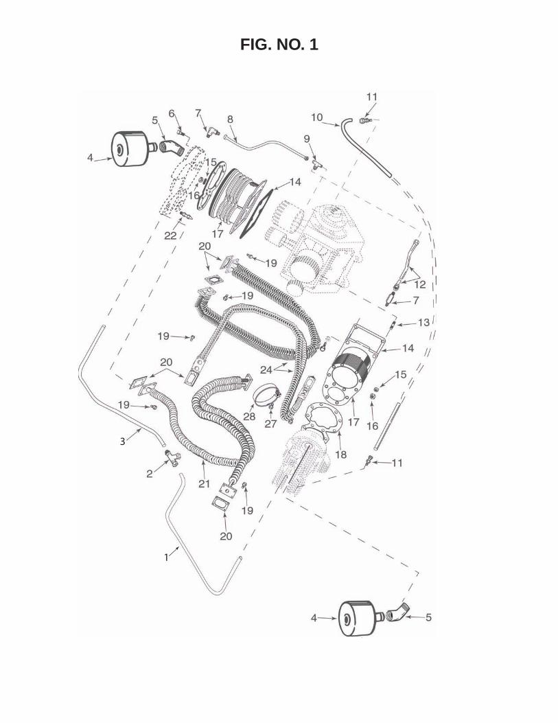
FIG. NO. 1

ILL# PARTS# DESCRIPTION QTY.
*1 45422 Copper Tubing - 1/4” O.D. x 20-1/2 Lg. 1
*2 45425 Tee - 1/4 x 1/4 x 1/4 1
*3 45446 Copper Tubing - 1/4 O.D. x 23 Lg. 1
4 48275 Muffler Assembly 2
__ 51291 Replaceable Muffle Filter Element 2
5 37350 Street Elbow - 1-1/2 x 45 degrees 2
6 30091 Hex Head Capscrew - 7/16 - 14 x 4 24
7 690 Breather Elbow 2
**8 39610 Breather Tube Assembly 1
9 43456 Tubing Tee - 3/8P x 3/8T x 38T 1
10 39097 Copper Tubing - 5/16 x 32 Lg. 1
11 12950 Straight Breather Connector 2
**12 43457 Breather Tube Assembly 1
13 38053 Stud - 1/2” - 13 x 2” 2
14 8701 Base Gasket 2
15 9286 Lockwasher - 1/2” (For Base Bolt) 12
16 9158 Nut - 1/2 -13 2
17 17119 Cylinder 2
18 38908 Cylinder Gasket 2
19 992 Flange Bolt - 5/16 - 18 x 7/8 24
20 38602 Cooler Flange Gasket 6
21 38920 Aftercooler Assembly 1
22 48633 Safety Valve Standard 2
23 18069 Base Bolt - 1/2” - 13 x1-1/2 10
24 38598 Intercooler Assembly 2
25 9156 Hex Nut - 1/4 -20 1
26 9522 Lockwasher - 1/4 1
27 94672 Bolt - 1/4 - 20 x 5/8 1
28 39267 Strap Cooler 1
* Parts used only TVX Pump.
** On pumps with centrifugal unloader use one Ref. #8 and on one Ref. #12 as shown.
On pumps without centrifugal unloader use two of Ref. #12
FIG. NO.1
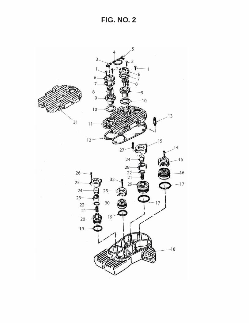
FIG. NO. 2
ILL# PARTS# DESCRIPTION QTY.
* 1 96472 Hex Head Capscrew - 1/4 - 20 x 5/8 12
* 2 18062 Hex Head Capscrew - 1/4 - 20 x 1-1/4 12
* 3 42384 Tubing Tee - 1/4P x 1/4T 2
* 4 45428 Copper Tubing 2
* 5 15362 Tubing Elbow - 1/4P x 1/4T x 90 2
* 6 45157 Unloader Cover 4
* 7 48778 Inlet Unloader Gasket 4
* 8 45163 Plunger & Cup Assembly 4
* 9 45153 Plunger Guide 4
*10 45158 Gasket 4
*11 45159 Cylinder Head Plate 2
12 38596 Cylinder Head Plate Gasket 2
13 8603 Intercooler Safety Valve 2
14 39203 Screw - 5/16 -18 x 1-1/2 4
15 38610 Hold Down Ring - L.P. 4
16 38737 Valve Assembly , L.P. Discharge 2
17 38609 Seat Gasket - L.P. 4
18 38595 Cylinder Head 2
19 38621 Seat Gasket - L.P. 4
20 38738 Valve Assembly - H.P. Inlet 4
* 21 45161 Plunger Spring 2
* 22 45166 Retaining Ring 4
* 23 7721 Finger - H.P. 4
*24 45156 Piston 4
25 38622 Hold Down Ring - H.P. 4
26 39255 Screw - 1/4-20 x 1-3/4 2
27 39254 Screw - 5/16 -18 x 1-3/4 2
* 28 45164 Finger - L.P. 1
29 38736 Valve Assembly - L.P. Inlet
30 38739 Valve Assembly - H.P. Discharge
31 38597 Head Plate - TV Pump
32 39256 Screw - 1/4 - 20 x 1-1/4
* Parts used only TVX Pump.
FIG. NO. 2
1
16
15
14
13
6
7
9
9
7
11
12
8
12
11
7
9
10
9
78
6
4
53
2
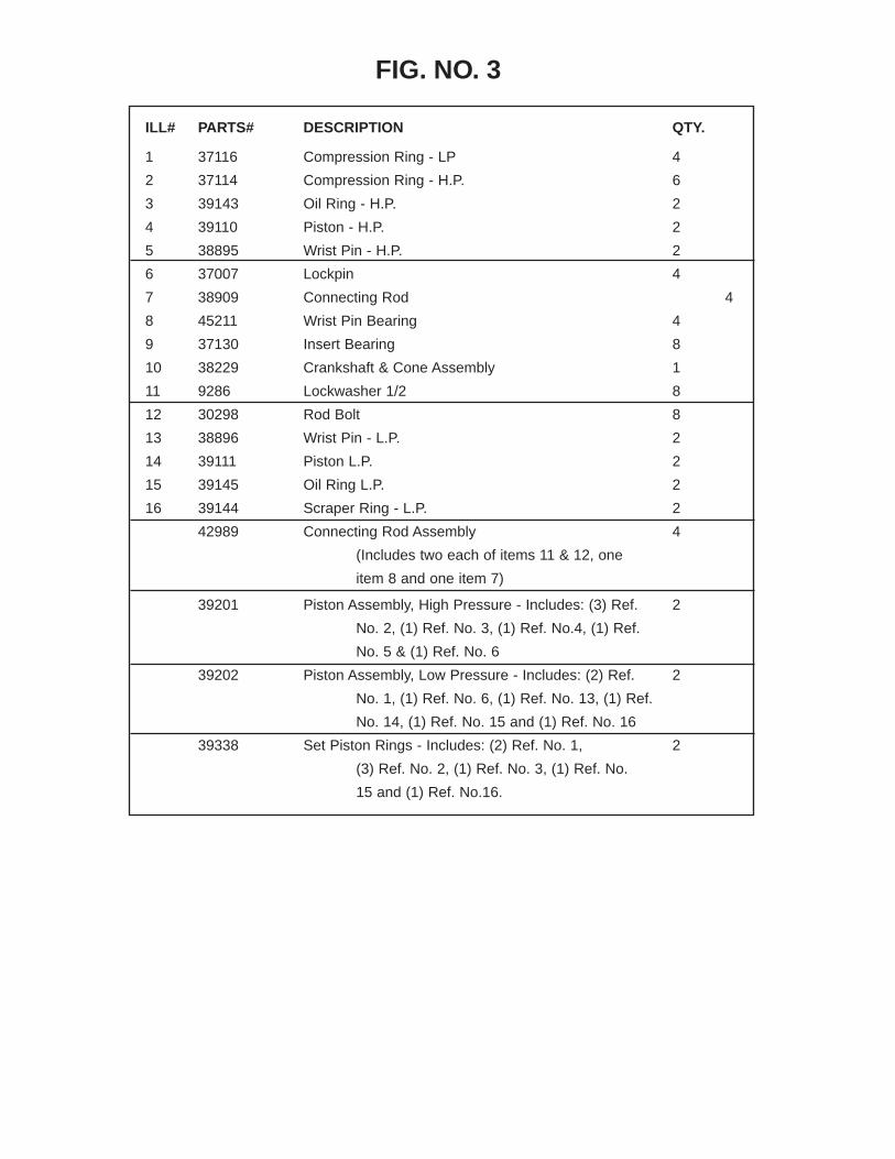
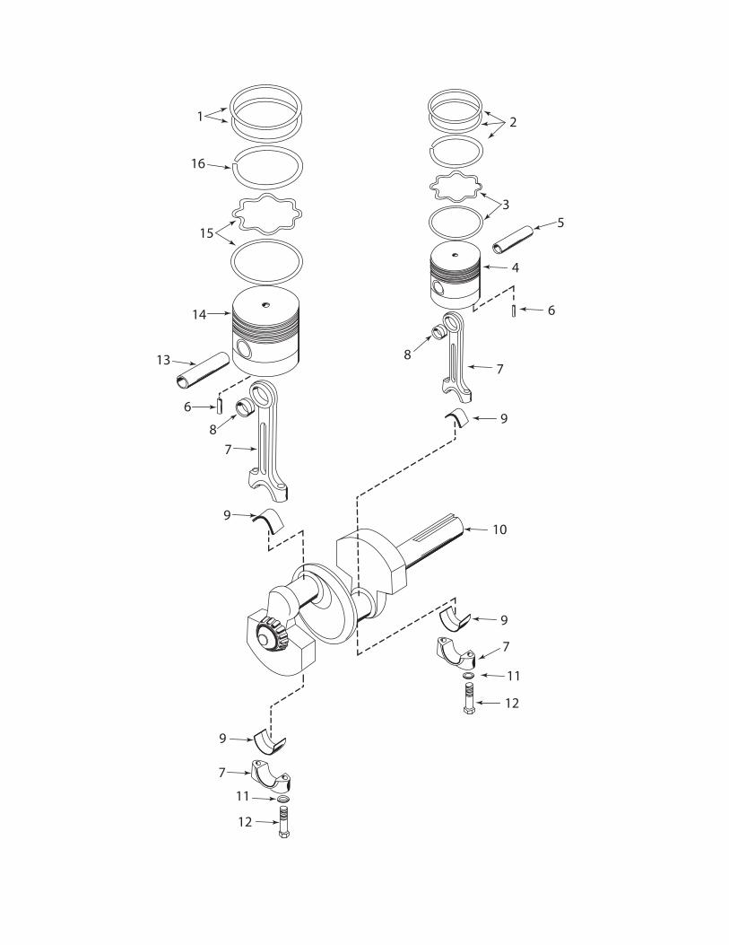
ILL# PARTS# DESCRIPTION QTY.
1 37116 Compression Ring - LP 4
2 37114 Compression Ring - H.P. 6
3 39143 Oil Ring - H.P. 2
4 39110 Piston - H.P. 2
5 38895 Wrist Pin - H.P. 2
6 37007 Lockpin 4
7 38909 Connecting Rod 4
8 45211 Wrist Pin Bearing 4
9 37130 Insert Bearing 8
10 38229 Crankshaft & Cone Assembly 1
11 9286 Lockwasher 1/2 8
12 30298 Rod Bolt 8
13 38896 Wrist Pin - L.P. 2
14 39111 Piston L.P. 2
15 39145 Oil Ring L.P. 2
16 39144 Scraper Ring - L.P. 2
42989 Connecting Rod Assembly 4
(Includes two each of items 11 & 12, one
item 8 and one item 7)
39201 Piston Assembly, High Pressure - Includes: (3) Ref. 2
No. 2, (1) Ref. No. 3, (1) Ref. No.4, (1) Ref.
No. 5 & (1) Ref. No. 6
39202 Piston Assembly, Low Pressure - Includes: (2) Ref. 2
No. 1, (1) Ref. No. 6, (1) Ref. No. 13, (1) Ref.
No. 14, (1) Ref. No. 15 and (1) Ref. No. 16
39338 Set Piston Rings - Includes: (2) Ref. No. 1, 2
(3) Ref. No. 2, (1) Ref. No. 3, (1) Ref. No.
15 and (1) Ref. No.16.
FIG. NO. 3

25
6
7
5
24
43
2
1
23
2221
20
19
8
9
10
811
12
13
14
715
16 17
18

ILL# PARTS# DESCRIPTION QTY.
1 98654 Pulley Bolt - 1/2” - 13 x 3 2
2 38593 Pulley Assembly - Includes Ref. #1,3, & 4 1
3 9286 Lockwasher - 1/2” 2
4 9158 Nut - 1/2” -13 2
5 38234 Base & Cup Assembly - Includes (1) Ref. #7 1
6 48047 Visual Oil Gauge 1
7 37107 Bearing Cup 2
8 37108 Bearing Cone 2
9 37109 Key 1
10 38229 Crankshaft & Cone Assembly - Includes (2) Ref. #8 1
11 37104 Oil Feeder Ring 1
12 37100 End Cover Gasket .015 Thick 1
13 37101 End Cover Gasket .006 Thick 1
14 37102 End Cover Gasket .003 Thick 1
15 38643 End Cover & Cup Assembly - Includes (1) Ref. #7 1
16 38490 Oil Filler Plug 1
17 38396 Oil Filler Plug Gasket 1
18 986 End Cover Bolts 3/8” - 16 x 1 8
19 33735 Oil Drain Cap 1
20 16959 Oil Drain Pipe 1
21 37103 Side PLate Gasket 2
22 37125 Side Plate 2
23 96472 Side plate Bolts 16
24 37525 Oil Seal 1
*__ 9347 Oil Drain Plug 1
25 38228 End Cover & Cup Assembly - For unit less centrifugal
unloader - Includes (1) Ref. #7
* Furnished with bare pump.
FIG. NO. 4

10
11 12
1314
1516
17
1819
21
20
1
3
2
3
1
54
6
7
8
9
FIG. NO. 5

ILL# PARTS# DESCRIPTION QTY.
1 38173 Weight 2
2 38628 Weight Retainer 1
3 38195 Spring 2
4 38190 Bolt - Special Sq. Head - 7/16 - 14 x LH 1
5 38191 Piston Stop Washer 1
6 39793 Spring 1
7 38177 Piston 1
8 38182 Valve Stem 1
9 38267 Housing Gasket 1
10 38258 Unloader Housing Assembly - Includes Ref. #12 & 21 1
11 96472 Hex Head Capscrew - 1/4 -20 x 5/8 Lg. 6
12 38188 Valve Guide 1
13 38185 Valve Retainer 1
14 9325 Ball - 1/4 Dia. 1
15 38194 Valve Return Spring 1
16 38184 Valve Retainer Nut 1
17 38178 Filter Nut 1
18 38192 Filter Screen 1
19 38193 Felt 1
20 38197 Rollpin - 5/16 dia. x 1-3/4 2
21 38174 Unloader Housing 1
NOTE: The items in Figure #5 are included on compressors with centrifugal unloader only.
FIG. NO. 5

1
14
13
12
12
11
10
1
2
20
11
19
19
18
9
1
1
1
6
16
17
9
1
2
3
5
6
7
8
9
9
15
LOW PRESSURE
DISCHARGE
INLET
DISCHARGE
INLET
HIGH PRESSURE
FIG. NO. 6
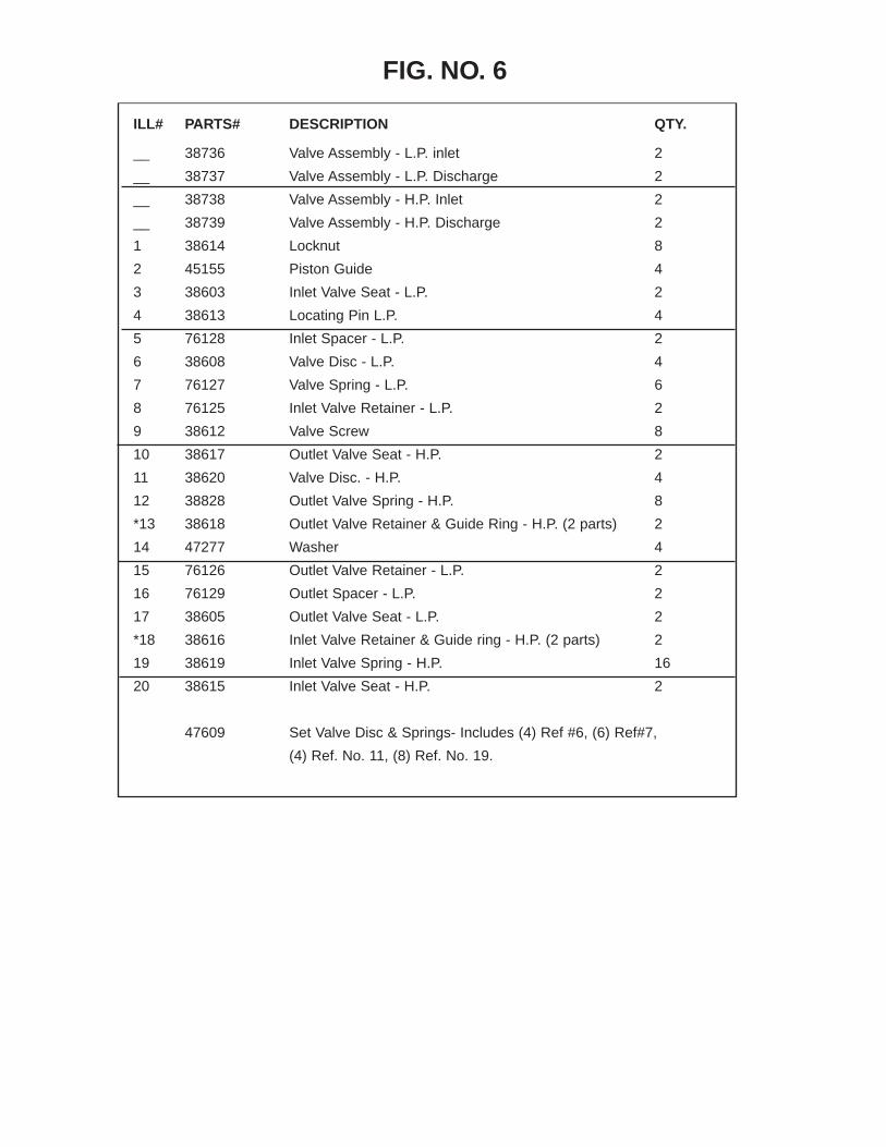
ILL# PARTS# DESCRIPTION QTY.
__ 38736 Valve Assembly - L.P. inlet 2
__ 38737 Valve Assembly - L.P. Discharge 2
__ 38738 Valve Assembly - H.P. Inlet 2
__ 38739 Valve Assembly - H.P. Discharge 2
1 38614 Locknut 8
2 45155 Piston Guide 4
3 38603 Inlet Valve Seat - L.P. 2
4 38613 Locating Pin L.P. 4
5 76128 Inlet Spacer - L.P. 2
6 38608 Valve Disc - L.P. 4
7 76127 Valve Spring - L.P. 6
8 76125 Inlet Valve Retainer - L.P. 2
9 38612 Valve Screw 8
10 38617 Outlet Valve Seat - H.P. 2
11 38620 Valve Disc. - H.P. 4
12 38828 Outlet Valve Spring - H.P. 8
*13 38618 Outlet Valve Retainer & Guide Ring - H.P. (2 parts) 2
14 47277 Washer 4
15 76126 Outlet Valve Retainer - L.P. 2
16 76129 Outlet Spacer - L.P. 2
17 38605 Outlet Valve Seat - L.P. 2
*18 38616 Inlet Valve Retainer & Guide ring - H.P. (2 parts) 2
19 38619 Inlet Valve Spring - H.P. 16
20 38615 Inlet Valve Seat - H.P. 2
47609 Set Valve Disc & Springs- Includes (4) Ref #6, (6) Ref#7,
(4) Ref. No. 11, (8) Ref. No. 19.
FIG. NO. 6

TROUBLESHOOTING
PROBLEM POSSIBLE CAUSE CORRECTIVE ACTION
1. Compressor will not operate. 1. No electrical power. 1. Turn on power. 2. Pressure switch not making contact 2. See pressure switch adjustment.
2. Excessive noise in operation 1. Loose pulley, flywheel, belt, beltguard, 1. Tighten. cooler, clamps or accessories. 2. Lack of oil in crankcase. 2. Check for possible damage to bearings, replenish oil. 3. Piston hitting the valve plate. 3. Remove the compressor cylinder head and inspect for foreign matter on top of the piston. Add a new gasket and reassemble the head. 4. Compressor floor mounting loose. 4. Tighten. 5. Defective crankcase. 5. Repair or replace. 6. Excessive crankshaft end play. 6. Adjust and shim properly.
3. Knock - same cycle as R.P.M. 1. Main bearings. 1. Replace bearings. 2. Connecting rod bearing. 2. TIghten.
4. Knock occurs while 1. Connecting rod bearings. 1. Replace rod. compressor is loading. 2. Wrist pins, wrist pin bearings. 2. Replace complete piston assembly.
5. Milky oil in oil reservoir. 1. Water entering oil reservoir due 1. Pipe air intake to less humid air\ to compressor operating in high source. humidity environment.
6. Excessive oil consumption. 1. Restricted air intake. 1. Clean or replace air filter. 2. Oil leaks. 2. Tighten bolts or replace gasket. 3. Worn piston rings. 3. Replace piston rings. 4. Wrong oil viscosity. 4. Drain oil, refill with oil or proper viscosity. See Lubrication Section. 5. Compressor titled too much. 5. Level compressor. 6. Scored cylinder. 6. Replace cylinder.
7. Oil in discharge air. 1. Compressor air intake restricted. 1. Clean air filter element and check for other restrictions in the intake system. 2. Worn piston rings. 2. Replace rings. 3. Excessive oil in compressor. 3. Drain down to full mark on sight gauge. 4. Wrong oil viscosity. 4. Check viscosity. See Lubrication Section. 5. Piston rings installed up-side down. 5. Install ring in proper position.
8. Compressor vibrates. 1. Mounting bolts loose. 1. Tighten. 2. Compressor not properly mounted. 2. Level compressor so that all feet touch the floor before tightening down. 3. Pulley and flywheel misaligned. 3. Realign. 4. Belts loose. 4. Tighten belts. See Maintenance Section. 5. Bent crankshaft. 5. Replace crankshaft.

TROUBLESHOOTING (continued)
PROBLEM POSSIBLE CAUSE CORRECTIVE ACTION
9. Air blowing our of inlet 1. Broken first stage inlet valve. 1. Replace valve assembly. 10. Insufficient pressure at point 1. Leaks or restriction. 1. Check for leaks or restriction of use. or piping. Repair. 2. Restricted air intake. 2. Clean or replace air filter element. 3. Slipping belts. 3. Tighten belts. See Maintenance Section. 4. Service hose too small. 4. Replace with larger hose. 5. Excessive air requirement. 5. Limit air requirement to compressor capacity.
11. Receiver does not hold pressure 1. Faulty check valve. 1. Bleed Tank! Disassemble check when compressor is unloaded. valve assembly, clean or replace faulty parts. DANGER - DO NOT DISASSEMBLE CHECK VALVE WITH AIR IN TANK. NOTE - CHECK VALVE IS ALWAYS THE FIRST VALVE IN THE LINE LEADING FROM THE TANK TO THE COMPRESSOR.
12. Excessive belt wear. 1. Pulley out of alignment. 1. Realign motor pulley with compressor flywheel. 2. Belts too tight. 2. Adjust tension. See Maintenance Section. 3. Belts too loose. 3. Adjust tension. See Maintenance Section. 4. Pulley or flywheel wobble. 4. Check for worn crankshaft, keyway or pulley bore, resulting from running with loose pulleys. Check for bent crankshaft. 5. Nick in belt grove of pulley or 5. File smooth. flywheel.
13. Excessive discharge air 1. Dirty cooling surfaces. 1. Clean cooling surfaces of cylinder, temperature. intercooler and discharge tube. 2. Poor ventilation. 2. Improve ventilation or relocate compressor. See Installation. 3. Blown head gasket. 3. Replace head gasket. 4. Restricted air intake 4. Clean or replace air filter element. 5. Worn valves. 5. Repair or replace valves.
14. Receiver pressure builds 1. Dirty air filter. 1. Clean or replace filter element. up slowly. 2. Blown cylinder head gasket. 2. Install new gasket. 3. Worn or broken low pressure 3. Install new head gasket. intake or discharge valves. 4. Air leaks. 4. Tighten joints. 5. Loose belts. 5. Tighten belts. See Maintenance Section. 6. Speed too slow. 6. Check speed.

Cutout pressure are adjustable from 60 PSI to 175 PSI with the standard silver spring. The differential (difference between cut-out and cut-in pressures) is typically set at the factory at about 15% of the cut-out pressure. This is usually a suitable differential and will not normally need to be read-justed.
1. Loosen only range screw jam nut first.2. Turn range screw clockwise to raise cut-out and pres-sure levels and counter clockwise to decrease cut-out and cut-in levels.3. Start compressor and note cut-out and cut-in pressures. Make adjustments as necessary using range adjustment screw; and when acceptable tighten range adjustment screw jam nut.4. Adjust the cut-in pressure to the desired level per steps 1, 2, and 3, above.5. Loosen differential screw jam nut and turn differen-tial screw clockwise to raise cut-out pressure and counter clockwise to decrease the the cut-out pressure. Tighten dif-ferential screw jam nut when desired cut-out pressure is set. Since step 5 should not change the desired cut-in -pressure set in step 4, adjustment is now complete.
Port Differential Jam Nut
Differential Adjustment Screw
Range Jam Nut
Range Adjustment Screw
Port
Port
REGULATOR ADJUSTMENT
LOAD GENIE

Air file 4.0*
Air filter cleaner 70-100 3.6*
Air motors 1 HP 7.0 2 HP 13.0 3 HP 19.0
Air polisher 16.0
Blow gun 90-100 2.4
Brake tester 70-100 3.6
Caulking gun 10-70 2.2
Circular saw 17.0
Die grinder 6.0
Drill, 3/8 inch 70-90 4.0*
Engine cleaner 90-100 5.0
Fender hammer 70-100 9.0*
Filing machine 90-100 5.0*
Grease gun 120-150 6.0*
Hydraulic lift 6.0-12.0*
Impact wrench 3/8 inch 70-90 3.0* 1/2 inch 70-90 4.0* 5/8 inch 70-90 5.0* 3/4 inch 70-90 8.0* 1 inch 70-90 12.0*
Air hammer 90-100 7.0*
Orbital sander 70-100 12.0*
Panel cutter 70-100 4.0
Nail hammer 90-100 4.0
Rim stripper 125-150 5.0
Spark plug cleaner 90-100 5.0
Air scaler 5.0
Spray gun Production 90-100 16.0* Touchup 90-100 8.0* Undercoating 90-100 19.0*
Tire bead breaker 125-150 12.0*
Tire changer 125-150 1.0
Tire hammer 90-100 12.0
Tire inflation line 125-150 1.4
Tire spreader 125-150 1.0
Transmission flusher 70-100 3.0
Carbon remover 70-100 3.0*
Burring tool 90-100 5.0*
Vacuum cleaner 125-150 6.0
Hydraulic floor jack 125-150 6.0
Radiator tester 90-100 1.1
Air saw 6.0
Vertical air sanders 5” 12.0 7” 16.0 9” 18.0
Vertical grinder 3” 6.0 4” 12.0 7” 24.0
Consult the spec. sheet supplied with your air tool or equipment for the exact operating pres-sure and air volume requirements.
*Continuous Run Tools
AIR CONSUMPTION CHART
PSI SCFM PSI SCFM

For one year from the date of purchase, the manufacturer will replace for the original purchaser free of charge, any part or parts found upon examination by an Authorized Service Center to be defective in material or workman-ship or both. All transportation charges or parts submitted for replacement under this warranty must be borne by the purchaser. There is no other express warranty, implied war-ranties, including those of merchantability and fitness for a particular purpose are limited to one year from the date of purchase and to the extent permitted by law, any and all implied warranties are excluded. This is the exclusive rem-edy, and liability for consequential damages under any and all warranties are excluded to the extent exclusion is permit-ted by law.
This warranty does not apply to electric motors or gasoline engines. These are covered by the Original Manufacturer’s Warranty and should be returned (by the customer) to their authorized service center for service.
All claims pertaining to the merchandise in this schedule, with the exception of warranty claims, must be filed with the manufacturer Air Compressors within 12 months of the invoice date, or they will not be honored. Prices, discount, and terms are subject to change without notice or as stipu-lated in specific product quotations. All agreements are con-tingent upon strikes, accidents, and other causes beyond
our control. All shipments are carefully inspected and counted before leaving the factory. Please inspect care-fully any receipt of merchandise, noting any discrepancy or damage on the carrier’s freight bill at time of delivery. Discrepancies or damage, which obviously occurred in transit, are the carrier’s responsibility and related claims should be made promptly directly to the carrier.
Returned merchandise will not be accepted without prior written authorization by the manufacturer and deductions from invoices for shortage or damage claims will not be allowed. Unless otherwise agreed to in writing, these terms and conditions will control in any transaction with the man-ufacturer, regardless of any different or conflicting terms as may appear on any order form now or later submitted by the buyer. All orders are subject to acceptance by the manufacturer.
Proof of purchase in the form of a bill of sale or receipted invoice, which is evidence that the unit is within the war-ranty period, must be presented to obtain warranty service.
This warranty is invalid if the factory-applied serial number has been altered or removed from the product, or an electric compressor has been used in conjunc-tion with a generator.
AIR COMPRESSORS WARRANTY POLICY
To locate the closest Authorized Service Center, or for service assistance or resolution of a service problem, or for product information and operation, call or write to:
Schrader Bridgeport International, Inc.205 Frazier Road
Altavista, VA 245171-800-345-0578
Schrader Bridgeport International, Inc. • P.O. Box 668 • 205 Frazier Road • Altavista, Virginia 24517
CUSTOMER SERVICES • SALES1-800-327-1335
TECHNICAL SERVICE • PARTS1-800-345-0578
AftercoolerDevice for cooling the air temperature after the final stage of compression. An aftercooler is used to cool the compressed air before entering the receiver tank.
ASME Tank Tanks made and inspected to meet standards of the American Society of Mechanical Engineers (AMSE). An AMSE certificate is on file for each tank, listing, registered serial numbers and certifying that the receiver has been inspected by independent agency in accordance with ASME standards. ASME tanks must be used where OSHA compliance is required.
Drain Valve/CockDevice used to drain moisture from air tanks. Can be manual or automatic.
Check ValvesA valve that permits air flow in one direction only.
Displacement Displacement of a compressor is the net volume actally dis-placed by the compressor pistons at rated machine speed or the volume of air swept through by the piston, usually expressed in cubic feet per minute. IMPORTANT NOTE: Displacement (CFM) should not be used when sizing a compressor-refer to flow requirements (SCFM).
Intercoolers Device used to remove heat between the first and second stages of a two stage compressor.
Non-code receiversCompressed air holding tanks which do not meet ASME stan-dards. Restricted to use in locations where a compliance with OSHA, state and local standards is not required.
Receiver TankUsed for storage of compressed air.Reciprocating CompressorUnit which achieves air compression by means of a reciprocating
cylindrical piston.
Single Stage Reciprocating CompressorAir compression takes place through one single step. The com-pressor may have two pistons, but compression still only takes place one time. The second piston is used to simply increase the volume of air being compressed. Typical operating pressure range is 80-90 PSI, (maximum 125 PSI).
Two Stage Compressor Air compression takes place througha two steps process. All two stage compressors must have at least two different size pistons. Air enters the first piston or stage and is compressed. It is then discharged into a second piston or second stage for final com-pression. Typical operating pressure range is 140-175 PSI (maxi-mum 200 PSI).
Load Genie/Un-loader Valve that allows air to enter the tank until the maximum air pres-sure is realized. Acts as a check valve and pressure switch while controlling the throttle on gas engines.
Pressure SwitchElectrical devise used to read the tank pressure while allowing machine to cycle. Controls the cut-in (cuts on air entering the tank) and cut-out (cuts off the air entering the tank).
Magnetic StarterControls amperage load and voltage to compressor unit, thereby protecting an electric motor.
Safety ValveValve used to blow off air at a certain set air pressure, thereby preventing damage to the internal parts of a pump.
GLOSSARY OF AIR COMPRESSOR TERMS