Embed Size (px)
Citation preview

Kit features.
• Ready-made—minimal assembly & finishing required.• Ready-covered covering.• Photo-illustrated step-by-step Assembly Manual.
Made in Vietnam.
SpecificationsWingspan ------------------------------ 63 in -------------------------- 160cm.Wing area ----------------------------- 728 sq.in ------------------ 47 sq.dm.Weight ---------------------------------- 8.4-9.9lbs -----------------3.8-4.5kg.Length ---------------------------------- 59.4 in ------------------------- 151cm.Recommended engine size ------ .91-1.25 cu.in ----------- 2-4stroke.Radio System required 6 channel with 6 digital servos.Flying skill level -------------------- Intermediate/advanced.
ASSEMBLY MANUAL
MS:56H
EXTRA 260. Instruction Manual.
2
INTRODUCTION.
Thank you for choosing the EXTRA 260 ARTF by SEAGULL MODELS. The EXTRA 260 wasdesigned with the intermediate/advanced sport flyer in mind. It is a semi scale airplane which iseasy to fly and quick to assemble. The airframe is conventionally built using balsa, plywood to makeit stronger than the average ARTF , yet the design allows the aeroplane to be kept light. You will findthat most of the work has been done for you already.Flying the EXTRA 260 is simply a joy.
This instruction manual is designed to help you build a great flying aeroplane. Please read thismanual thoroughly before starting assembly of your EXTRA 260. Use the parts listing below toidentify all parts.
WARNING.
Please be aware that this aeroplane is not a toy and if assembled or used incorrectly it iscapable of causing injury to people or property. WHEN YOU FLY THIS AEROPLANE YOUASSUME ALL RISK & RESPONSIBILITY. If you are inexperienced with basic R/C flight we strongly recommend you contact your R/Csupplier and join your local R/C Model Flying Club. R/C Model Flying Clubs offer a variety of trainingprocedures designed to help the new pilot on his way to successful R/C flight. They will also be ableto advise on any insurance and safety regulations that may apply.
ADDITIONAL ITEMS REQUIRED.
! .91-1.25 2-4 stroke engine.! Computer radio with six digital
servos.! Glow plug to suit engine.! Propeller to suit engine.! Protective foam rubber for radio
system.! Silicone fuel line.
PARTS LISTING.
FUSELAGE ASSEMBLY! (1) Fuselage.! (1) Canopy hatch.
WING ASSEMBLY
! (1) Right wing half/ aileron.! (1) Left wing half/ aileron.! (1) Aluminium dihedral brace.
Horizon Hobby, Inc. guarantees this kit to be free from defects in both material and workmanshipat the date of purchase. This warranty does not cover any parts damage by use or modification. Inno case shall Horizon Hobby’s liability exceed the original cost of the purchased kit. Further, HorizonHobby reserves the right to change or modify this warranty without notice. In that Horizon Hobbyhas no control over the final assembly or material used for the final assembly, no liability shall beassumed nor accepted for any damage resulting from the use by the user of the final user-assembledproduct. By the act of using the user-assembled product, the user accepts all resulting liability.
Once assembly of the model has been started, you must contact Horizon Hobby, Inc. directlyregarding any warranty question that you have. Please do not contact your local hobby shop regardingwarranty issues, even if that is where you purchased it. This will enable Horizon to better answeryour questions and service you in the event that you may need any assistance. If the buyer is notprepared to accept the liability associated with the use of this product, the buyer is advised toreturn this kit immediately in new and unused condition to the place of purchase.
Horizon Hobby4105 Fieldstone RoadChampaign, Illinois 61822(217) 355-9511

www.seagullmodels.com
3
Please contact Horizon Hobby for product supportand technical assistance at 877-504-0233.Replacement parts are available from your localdealer or through Horizon Hobby.HORIZON HOBBY DISTRIBUTIONS INC4105 Fieldstone Rd, Champaign, IL 61822-USA
TOOLS & SUPPLIES NEEDED.
! Thick cyanoacrylate glue.! 30 minute epoxy.! 5 minute epoxy.! Hand or electric drill.! Assorted drill bits.! Modelling knife.! Straight edge ruler.! 2mm ball driver.! Phillips head screwdriver.! 220 grit sandpaper.! 90° square or builder’s triangle.! Wire cutters.! Masking tape & T-pins.! Thread-lock.! Paper towels.
To avoid scratching your new aeroplanewe suggest that you cover your workbenchwith an old towel. Keep a couple of jars orbowls handy to hold the small parts after youopen the bags. Please trial fit all parts. Make sure youhave the correct parts and that they fit and arealigned properly before gluing! This will ensureproper assembly as the EXTRA 260 is madefrom natural materials and minor adjustmentsmay have to be made.
The paint and plastic parts used in thiskit are fuel proof. However, they are not tolerantof many harsh chemicals including the follow-ing: paint thinner, cyano-acrylate glue accel-erator, cyanoacrylate glue de-bonder andacetone. Do not let these chemicals come incontact with the colours on the covering andthe plastic parts.
Tail section assembly
! (1) Horizontal stabilizer/ elevatorhalves.
! (1) Rudder halves.
Some more parts.
HARDWARE PACK
COWLINGLanding gear.....
NOTE.

EXTRA 260. Instruction Manual.
4
The control surfaces, including theailerons, elevators, and rudder, areprehinged with hinges installed, but thehinges are not glued in place. It isimperative that you properly adhere thehinges in place per the steps that followusing a high-quality thin C/A glue.
! 1) Carefully remove the aileron from oneof the wing panels. Note the position of thehinges.
! 2) Remove each hinge from the wing paneland aileron and place a T-pin in the center ofeach hinge. Slide each hinge into the wingpanel until the T-pin is snug against the wingpanel. This will help ensure an equal amountof hinge is on either side of the hinge line whenthe wing panel is mounted to the aileron.
HINGING THE AILERONS.
Note:
! 3) Slide the wing panel on the aileron untilthere is only a slight gap. The hinge is nowcentered on the wing panel and aileron.Remove the T-pins and snug the aileronagainst the wing panel. A gap of 1/64” or lessshould be maintained between the wing paneland aileron.
! 4)Deflect the aileron and completelysaturate each hinge with thin C/A glue. Theailerons front surface should lightly contact thewing during this procedure. Ideally, when the
Hinge.
T-pin.
Hinge.
T-pin.
T-pin.
! 5) Turn the wing panel over and deflect theaileron in the opposite direction from theopposite side. Apply thin C/A glue to eachhinge, making sure that the C/A penetrates intoboth the aileron and wing panel.
The hinge is constructed of a specialmaterial that allows the C/A to wick orpenetrate and distribute throughout thehinge, securely bonding it to the woodstructure of the wing panel and aileron.
hinges are glued in place, a 1/64” gap or lesswill be maintained throughout the lengh of theaileron to the wing panel hinge line.
Note:
T-pin.
C/A glue.
www.seagullmodels.com
5
Work the aileron up and down severaltimes to “work in” the hinges and checkfor proper movement.
HINGING THE ELEVATOR.
Note:
! 8) After both ailerons are securely hinged,firmly grasp the wing panel and aileron tomake sure the hinges are securely glued andcannot be pulled out. Do this by carefullyapplying medium pressure, trying to separatethe aileron from the wing panel. Use cautionnot to crush the wing structure.
! 7) Repeat this process with the other wingpanel, securely hinging the aileron in place.
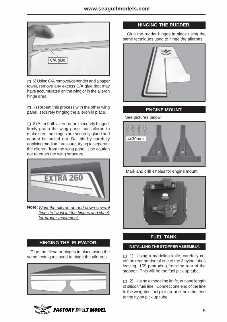
! 6) Using C/A remover/debonder and a papertowel, remove any excess C/A glue that mayhave accumulated on the wing or in the aileronhinge area.
C/A glue.
HINGING THE RUDDER.
Glue the elevator hinges in place using thesame tectniques used to hinge the ailerons.
Glue the rudder hinges in place using thesame tectniques used to hinge the ailerons.
ENGINE MOUNT. See pictures below:
Mark and drill 4 holes for engine mount.
4x30mm.
! 1) Using a modeling knife, carefully cutoff the rear portion of one of the 3 nylon tubesleaving 1/2” protruding from the rear of thestopper. This will be the fuel pick up tube.
! 2) Using a modeling knife, cut one lengthof silicon fuel line. Connect one end of the lineto the weighted fuel pick up and the other endto the nylon pick up tube.
INSTALLING THE STOPPER ASSEMBLY.
FUEL TANK.

EXTRA 260. Instruction Manual.
6
Vent tube.Fuel Pick-up Tube.
Fuel Fill Tube.
Carefully use a lighter or heat gun topermenently set the angle of the vent tube. Important: When the stopper assembly isinstalled in the tank, the top of the vent tubeshould rest just below the top surface of thetank. It should not touch the top of the tank.
! 4) Test fit the stopper assembly into thetank. It may be necessary to remove some ofthe flashing around the tank opening using amodeling knife. If flashing is present, makesure none falls into the tank.
! 5) With the stopper assembly in place,the weighted pick-up should rest away fromthe rear of the tank and move freely inside thetank. The top of the vent tube should rest justbelow the top of the tank. It should not touchthe top of the tank.
! 6) When satisfied with the alignment ofthe stopper assembly tighten the 3mm x 20mmmachine screw until the rubber stopper ex-pands and seals the tank opening. Do notovertighten the assembly as this could causethe tank to split.
You should mark which tube is the ventand which is the fuel pick-up when you attachfuel tubing to the tubes in the stopper. Oncethe tank is installed inside the fuselage, it maybe difficult to determine which is which.
Attach the silicone fuel and pressure pipesto the tank. The lower pipe is the ‘feed’ and theupper two the ‘pressure and fill’. The fill pipe isthe next pipe.
Balsa wood.
! 3) Carefully bend the second nylon tubeup at a 45º angle. This tube is the vent tube.
Rubber band.
Balsa wood.
Fuel tank.

www.seagullmodels.com
7
Fuel pick-uptube. Fuel fill tube.
Vent tube.
Blow through one of the lines to ensurethe fuel lines have not become kinked insidethe fuel tank compartment. Air should flowthrough easily.
! 1) Locate and cut out the covering film fromthe servo holes in both sides of fuselage.
! 2) Install the rubber grommets and brasscollets onto the elevator servo. Test fit theservo into the elevator servo mount.
! 3) Secure the servos with the screws pro-vided with your radio system.
Because the size of servos differ, you mayneed to adjust the size of the precut openingin the mount. The notch in the sides of themount allow the servo lead to pass through.
Remove covering.
Right side.
Elevator servo.
Left side.
Elevator servo.
INSTALLING THE FUSELAGE SERVO.
Throttle servo.
Rudder servo.
Servo tray.
Engine .91 - 2 stroke.
Engine 1.25 - 4 stroke. We recommended to use long servos arm( 70mm diameter) for all servos without throttleservo.
ELEVATOR SERVO INSTALLATION.
C/A glue.

EXTRA 260. Instruction Manual.
8
Wing bottom.Thread.
Small weight.
Thread. Small weight.
INSTALLING THE SWITCH.
Remove covering.
Switch.
Install the switch into the precut hole in theside, in the fuselage.
Because the size of servos differ, youmay need to adjust the size of the precut open-ing in the mount. The notch in the sides ofthe mount allow the servo lead to pass through.
INSTALLING THE AILERON SERVOS.
We recommended to use long servos arm( 70mm diameter) for all servos without throttleservo.
Install the rubber grommets and brasscollets onto the aileron servo. Test fit theservo into the aileron servo mount.
Using a small weight (Weighted fuel pick-upworks well) and thread, feed the string throughthe wing as indicated.
Rudder servo.
Throttle servo.
Servos. Thread.
Small weight.

www.seagullmodels.com
9
Wing bottom.
HORIZONTAL STABILIZER.
Attach the string to the servo lead andcarefully thread it though the wing. Once youhave thread the lead throught the wing, removethe string so it can use for the other servolead. Tape the servo lead to the wing to preventit from falling back into the wing.
Electric wire. Thread.
Repeat the procedure for orther winghaft.
Plastic tape.
Aileron electric.
Wing panel bottom.
Thread.
Electric wire.
Pull.
Secure the servos with the screws pro-vided with your radio system.
!1) Using a ruler and a pen, locate thecenterline of the horizontal stabilizer, at the trail-ing edge, and place a mark. Use a triangleand extend this mark, from back to front,across the top of the stabilizer. Also extendthis mark down the back of the trailing edge ofthe stabilizer.
! 2) Using a modeling knife, carefully removethe covering at mounting slot of horizontal sta-bilizer ( both side of fuselage).
Center line.
! 3) Slide the stabilizer into place in the pre-cut slot in the rear of the fuselage. The stabi-lizer should be pushed firmly against the frontof the slot.
EXTRA 260. Instruction Manual.
10
! 8) After the epoxy has fully cured, re-move the masking tape or T-pins used to holdthe stabilizer in place. Carefully inspect theglue joints. Use more epoxy to fill in any gapsthat may exist that were not filled previouslyand clean up the excess using a paper toweland rubbing alcohol.
Covered woodfiller piece.
Remove covering.
! 7) When you are sure that everything isaligned correctly, mix up a generous amountof 30 Minute Epoxy. Apply a thin layer to thetop and bottom of the stabilizer mounting areaand to the stabilizer mounting platform sidesin the fuselage. Slide the stabilizer in place
When cutting through the covering toremove it, cut with only enough pressure toonly cut through the covering itself. Cuttinginto the balsa structure may weaken it.
! 6) Using a modeling knife, carefully re-move the covering that overlaps the stabilizermounting platform sides in the fuselage. Re-move the covering from both the top and thebottom of the platform sides.
Remove covering.
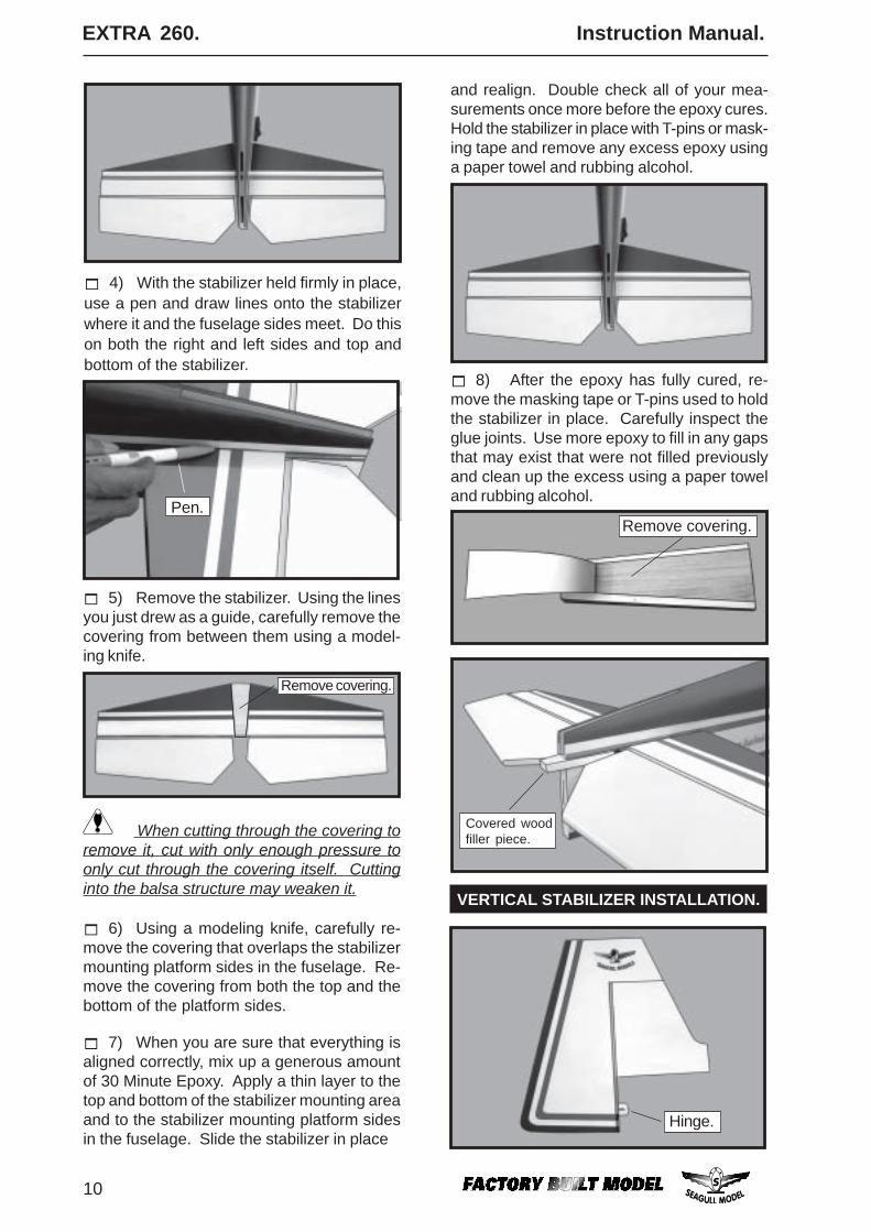
! 4) With the stabilizer held firmly in place,use a pen and draw lines onto the stabilizerwhere it and the fuselage sides meet. Do thison both the right and left sides and top andbottom of the stabilizer.
! 5) Remove the stabilizer. Using the linesyou just drew as a guide, carefully remove thecovering from between them using a model-ing knife.
Pen.
and realign. Double check all of your mea-surements once more before the epoxy cures.Hold the stabilizer in place with T-pins or mask-ing tape and remove any excess epoxy usinga paper towel and rubbing alcohol.
Hinge.
VERTICAL STABILIZER INSTALLATION.
www.seagullmodels.com
11
Hinge slot.
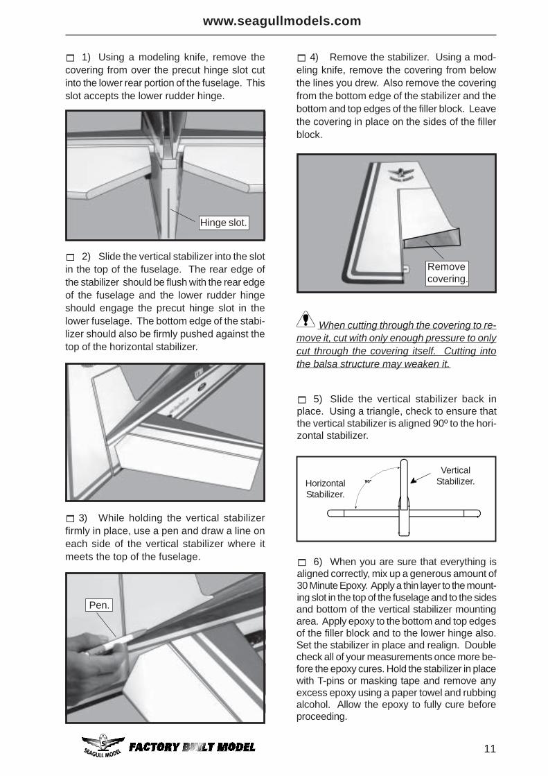
! 1) Using a modeling knife, remove thecovering from over the precut hinge slot cutinto the lower rear portion of the fuselage. Thisslot accepts the lower rudder hinge.
! 2) Slide the vertical stabilizer into the slotin the top of the fuselage. The rear edge ofthe stabilizer should be flush with the rear edgeof the fuselage and the lower rudder hingeshould engage the precut hinge slot in thelower fuselage. The bottom edge of the stabi-lizer should also be firmly pushed against thetop of the horizontal stabilizer.
! 3) While holding the vertical stabilizerfirmly in place, use a pen and draw a line oneach side of the vertical stabilizer where itmeets the top of the fuselage.
When cutting through the covering to re-move it, cut with only enough pressure to onlycut through the covering itself. Cutting intothe balsa structure may weaken it.
Removecovering.
! 4) Remove the stabilizer. Using a mod-eling knife, remove the covering from belowthe lines you drew. Also remove the coveringfrom the bottom edge of the stabilizer and thebottom and top edges of the filler block. Leavethe covering in place on the sides of the fillerblock.
Pen.
! 6) When you are sure that everything isaligned correctly, mix up a generous amount of30 Minute Epoxy. Apply a thin layer to the mount-ing slot in the top of the fuselage and to the sides
! 5) Slide the vertical stabilizer back inplace. Using a triangle, check to ensure thatthe vertical stabilizer is aligned 90º to the hori-zontal stabilizer.
90º
VerticalStabilizer.Horizontal
Stabilizer.
and bottom of the vertical stabilizer mountingarea. Apply epoxy to the bottom and top edgesof the filler block and to the lower hinge also.Set the stabilizer in place and realign. Doublecheck all of your measurements once more be-fore the epoxy cures. Hold the stabilizer in placewith T-pins or masking tape and remove anyexcess epoxy using a paper towel and rubbingalcohol. Allow the epoxy to fully cure beforeproceeding.

EXTRA 260. Instruction Manual.
12
INSTALLING THE AILERON LINKAGE.
! 1) Aileron control horn: Mix a small amount of 30 minute epoxy andlightly coat the inside of the hole in the aileronand the control horn screw.
! 2) Thread the screw (insert the aluminiumwasher) into the hole from the top of surface.Wipe away any excess epoxy on the wing andscrew with rubbing alcohol and a paper towel.Screw the M3 nut (insert the aluminiumwasher) in place as shown. Alllow the epoxyto fully cure.
Wing.
Aileron.
Aluminium washer.
M3 nut.
M3 lock nut.
Wing bottom.
M3 control horn.
Wing bottom.
Aileron control horn.
Repeat the procedure for orther wing.
3x45mm.
C/A glue.
ELEVATOR CONTROL HORN INSTALLATION.
! 1) Elevator control horn: Mix a small amount of 30 minute epoxy andlightly coat the inside of the hole in the elevatorand the control horn screw.
! 2) Thread the screw (insert the aluminiumwasher) into the hole from the top of surface.Wipe away any excess epoxy on the fin andscrew with rubbing alcohol and a paper towel.Screw the M3 nut (insert the aluminiumwasher) in place as shown. Alllow the epoxyto fully cure.
Horizontal fin.
Elevator.
Elevator control horn.

www.seagullmodels.com
13
Repeat the procedure for ortherelevator.
! 1) Position the rudder control horn on theleft - right side of the rudder.
! 2) Locate the two nylon control horns, twonylon control horn backplates and threemachine screws.
3x30mm.
2x30mm.
RUDDER CONTROL HORNINSTALLATION.
Ruddercontrol horn.
! 5) Mount the control horns by inserting thebolts through the control horn bases andelevator halves, then into the mountingbackplates. Do not overtighten the nuts or thebackplates may crush the wood.
! 3) Position the rudder horn on the bothside of rudder. The clevis attach- ment holesshould be positioned over the hinge line.
! 4) Using a 1.5mm drill bit and the controlhorns as a guide, drill the mounting holesthrough the rudder halves.
Ruddercontrol horn.
AILERON PUSHROD INSTALLATION.
Pushrod.
55mm.
C/A glue.
M3 lock nut.
Aileron pushrods assembly follow picturesbelow.

EXTRA 260. Instruction Manual.
14
! 2) With the radio on, check the operationof the rudder. Adjust the cables so when therudder servo is centered, the rudder iscentered as well. There will be tension on thecables. Adjustments can be made at the ruddercontrol horn and at the servo arm. Once
Left side.
Cable.
adjustments are made, secure the servo armto the rudder arm servo using the screw thatcame with the servo
Pushrod.
Cable.
Metal clevis.Control horn.
Elevator pushrod.
Repeat the procedure for ortherelevator.
RUDDER PULL PULL CABLEINSTALLATION.
M3 lock nut.
See pictures below:
! 1) Insert servo arm into servo.
150mm.
ELEVATOR PUSHROD INSTALLATION.
Repeat the procedure for elevatorpushrod as same as aileron pushrod.
Repeat the procedure for ortheraileron.

www.seagullmodels.com
15
WHEEL AND WHEEL PANTS.
! 2) Follow diagram below for wheel pantinstallation:
! 1) Assemble and mounting the wheel pantsas shown in the following pictures.
Wheel Collar.
Axle.
Wheel.Nut.
Wheel Pant.
Landing Gear.
Nut.
Plywood Washer.
14mm.
7mm.
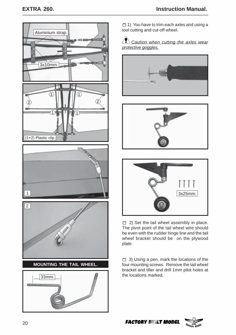
! 3) You have to trim each axles and using atool cutting and cut-off wheel.
Caution when cutting the axles wearprotective goggles.
57mm.
Plywood Washer.

EXTRA 260. Instruction Manual.
16
Landinggear.
! 4) A drop of C/A glue on the wheel collarscrews will help keep them from coming loseduring operation.
Repeat the process for the other wheel.
!1) The blind nuts for securing the landinggear are already mounted inside the fuselage.
!2) Using the hardware provided, mount themain landing gear to the fuselage.
INSTALLING THE MAIN LANDING GEAR.
MOUNTING THE ENGINE.
! 1) Install the pushrod housing through thepredrilled hole in the firewall and into the servocompartment. The pushrod housing shouldprotrude 1/4" out past the front of the firewall.
Make a Z-Bend 1/4" from one end of the plainwire pushrod.
! 2) Place your engine onto the enginemount. Adjust the engine is centered of theedges of the engine case.
! 4) Remove the engine. Using an drill bit,drill the mounting holes through the enginemount at the four locations marked.
! 3) When you are satisfied with the align-ment, mark the locations of the enginemounting.
6 X 20mm.
140mm.
lite-plywood block.

www.seagullmodels.com
17
! 6) Attach the Z-Bend in the pushrod wire tothe throttle arm on the carburetor. You will needto remove the throttle arm from the car- buretorto be able to attach the Z-bend. Whencomplete, re-attach the throttle arm to the car-buretor.
! 5) Bolt the engine to the engine mount usingthe four machine screws. Double check thatall the screws are tight before proceeding.
4.2mm.
4x30mm.
Engine .91 - 2 stroke.
4x30mm.
Pushrod wire.
Engine 1.25 - 4 stroke.
140mm.
COWLING.! 1) Slide the fiberglass cowl over the en-gine and line up the back edge of the cowl withthe marks you made on the fuselage then trimand cut.
Pushrod wire.
3x10mm.
Trim and cut.

EXTRA 260. Instruction Manual.
18
! 3) Install the muffler and muffler extensiononto the engine and make the cutout in thecowl for muffler clearance. Connect the fueland pressure lines to the carburetor, mufflerand fuel filler valve. Secure the cowl to fuse-lage using the 3x10mm screws (4).
opening. Use the spinner backplate as a guide.Hold the cowl firmly in place using pieces ofmasking tape.
The propeller should not touch any partof the spinner cone. If it does, use a sharpmodeling knife and carefully trim away thespinner cone where the propeller comes incontact with it.
Install the spinner backplate, propeller andspinner cone.
INSTALLING THE SPINNER.
1.5mm wire(needle valve).
! 2) While keeping the back edge of thecowl flush with the marks, align the front ofthe cowl with the crankshaft of the engine. Thefront of the cowl should be positioned so thecrankshaft is in nearly the middle of the cowl
Because of the size of the cowl, it may benecessary to use a needle valve extensionfor the high speed needle valve. Make thisout of sufficient length 1.5mm wire and installit into the end of the needle valve. Secure thewire in place by tightening the set screw in theside of the needle valve.
Trim and cut.
3 x 10mm.

www.seagullmodels.com
19
INSTALLING TAIL STRUT SYSTEM.
Tail strut system assembly follow picturesbelow.
3x10mm.
3.2mm drill bit.
Turnbuckle.
Horizontal stabilizer.
M3 lock nut.
14cm. 8cm.
0cm.
EXTRA 260. Instruction Manual.
20
2
1
33mm.
MOUNTING THE TAIL WHEEL.
! 2) Set the tail wheel assembly in place.The pivot point of the tail wheel wire shouldbe even with the rudder hinge line and the tailwheel bracket should be on the plywoodplate.
! 3) Using a pen, mark the locations of thefour mounting screws. Remove the tail wheelbracket and tiller and drill 1mm pilot holes atthe locations marked.
3x25mm.
! 1) You have to trim each axles and using atool cutting and cut-off wheel.
Caution when cutting the axles wearprotective goggles.
3x10mm.
Aluminium strap.
1
2
1
21
1
(1+2) Plastic clip.

www.seagullmodels.com
21
Tie wrap.
Receiver.
! 2) Install the rubber grommets and brasscollets onto the throttle servo. Test fit the servointo the throttle servo mount.
! 1) Install adjustable servo connector in theservo arm.
THROTTLE SERVO ARMINSTALLATION.
Because the size of servos differ, you mayneed to adjust the size of the precut openingin the mount. The notch in the sides of themount allow the servo lead to pass through.
! 3) Secure the servos with the screws pro-vided with your radio system.
! 4) Install the pushrod throttle.
Adjustable Servoconnector.
Servo arm.
! 4) Secure the tail wheel bracket in placeusing two 3x25mm wood screws. Be carefulnot to overtighten the screws.
Throttle.
! 1) Plug the six servo leads and the switchlead into the receiver. Plug the battery packlead into the switch also.
! 2) Wrap the receiver and battery pack inthe protective foam rubber to protect themfrom vibration.
! 3) Route the antenna in the antenna tubeinside the fuselage and secure it to the bot-tom of fuselage using a plastic tape. See pic-ture below.
Antenna.Antenna tube.
INSTALLING THE RECEIVER.

EXTRA 260. Instruction Manual.
22
Insert two wing panels as pictures below:
ATTACHMENT WING-FUSELAGE.
Attach the aluminium tube into fuselage.
Wing bolts.
!1) It is critical that your airplane be bal-anced correctly. Improper balance will causeyour plane to lose control and crash. The cen-ter of gravity is locate 7-8cm back from theleading edge of the wing, measured at wingtip.
!2) If the nose of the plane falls, the planeis nose heavy. To correct this first move thebattery pack further back in the fuselage. Ifthis is not possible or does not correct it, sticksmall amounts of lead weight on the fuselage
BALANCING.
sides under the horizontal stabilizer. If the tailof the plane falls, the plane is tail heavy. Tocorrect this, move the battery and receiver for-ward orif this is not possible, stick weight ontothe firewall or use a brass heavy hub spinnerhub, similar to those offered by Harry Higley.When balanced correctly, the airplane shouldsit level or slightly nose down when you lift itup with your fingers.
!2) Turn on the radio system, and with thetrim tabs on the transmitter in neutral, centerthe control surfaces by making adjustmentsto the clevises or adjustable servo connectors.The servo arms should be centered also.
CONTROL THROWS.
!1) We highly recommend setting up theEXTRA 260 using the control throws listed atright. We have listed control throws for bothLow Rate (initial test flying/sport flying) andHigh Rate (aerobatic flying).
! 3) When the elevator, rudder and aileroncontrol surfaces are centered, use a ruler andcheck the amount of the control throw in eachsurface. The control throws should bemeasured at the widest point of each sur-face!
Antenna.

www.seagullmodels.com
23
! 4) By moving the position of the adjust-able control horn out from the control surface,you will decrease the amount of throw of thatcontrol surface. Moving the adjustable con-trol horn toward the control surface will in-crease the amount of throw.
INITIAL FLYING/SPORT FLYING
Do not use the aerobatic settings forinitial test flying or sport flying.
Ailerons: 5/8” up 1/2” down Elevator: 3/4” up 3/4” down Rudder: 2 1/2” right and left
AEROBATIC FLYING Ailerons: 1” up 7/8” down Elevator: 1 1/4” up 1 1/4”down Rudder: 3 1/2” right and left
FLIGHT PREPARATION.
! A) Check the operation and direction ofthe elevator, rudder, ailerons and throttle.
! B) Plug in your radio system per themanufacturer's instructions and turn every-thing on.
! E)Check the throttle. Moving the throttlestick forward should open the carburetor bar-rel. If it does not, flip the servo reversing switchon your transmitter to change the direction.
! F) From behind the airplane, look at theaileron on the right wing half. Move the aileronstick to the right. The right aileron should moveup and the other aileron should move down. Ifit does not, flip the servo reversing switch onyour transmitter to change the direction.
! D) Check the rudder. Looking from be-hind the airplane, move the rudder stick to theright. The rudder should move to the right. If itdoes not, flip the servo reversing switch onyour transmitter to change the direction.
! C) Check the elevator first. Pull back onthe elevator stick. The elevator halves shouldmove up. If it they do not, flip the servo re-versing switch on your transmitter to changethe direction.
!5) If your radio transmitter is equippedwith dual rate switches double check that theyare on the low rate setting for your first fewflights.
PREFLIGHT CHECK.
!1) Completely charge your transmitterand receiver batteries before your first day offlying.
!2) Check every bolt and every glue jointin the EXTRA 260 to ensure that everything istight and well bonded.
!3) Double check the balance of the air-plane. Do this with the fuel tank empty.
!4) Check the control surfaces. All shouldmove in the correct direction and not bind inany way.
!6) Check to ensure the control surfacesare moving the proper amount for both lowand high rate settings.
!8) Properly balance the propeller. An outof balance propeller will cause excessive vi-bration which could lead to engine and/or air-frame failure.
We wish you many safe andenjoyable flights with yourEXTRA 260.
!7) Check the receiver antenna. It shouldbe fully extended and not coiled up inside thefuselage.