Embed Size (px)
Citation preview
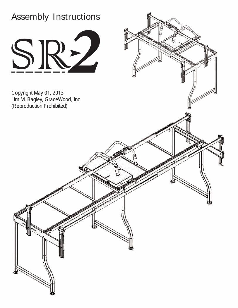
Copyright May 01, 2013Jim M. Bagley, GraceWood, Inc(Reproduction Prohibited)
Assembly Instructions

pg. 2
Welcome!
This quilting frame has been designed to be simple and practical for those new to machine quilting as well as easy to assemble. We hope that you will enjoy quilting for a lifetime.
As you begin assembly of your new Start Right 2 frame, keep in mind the following:
• The assembly will be simple and step by step;• Read through each step completely before beginning that step• Using the parts list as a reference, take the parts out of the box and make sure that you have them all.• Identify your hardware packets: All hardware is separated by type and each packet is labeledforeaseinidentification.
Warranty Informationfor your Grace Machine Quilting Frame
The Machine Quilting Frame has a One-Year limited warranty on all parts. The Grace Company will repair or replace, at its discretion, any part with manufacturing defects. This warranty does not cover parts damaged through misuse, improper storage, improper assembly, loss, natural events, and willful destruction. Parts must be returned to the Grace Company, shipping prepaid, before they can be repaired or replaced. We will promptly return the repaired/replaced part at our expense within a year of the purchase date.
Table of ContentsPart ListPart List .......................................................................................................................... 3
Assembly Steps Step 1-Foot Assembly ...................................................................................................... 5Step 2-Leg Assembly ....................................................................................................... 5Step 3-Table Brace Assembly ............................................................................................ 6Step 4-Frame End Left & Right Assembly .......................................................................... 6Step 5-Tracks Assembly ................................................................................................... 7Step 6-Rail Holder Bracket Assembly ................................................................................. 8Step 7-Rails Assembly ...................................................................................................... 9Step 8-Top Plate Assembly ............................................................................................. 10Step 9-Placing the Carriage ............................................................................................ 10Step 10-Placing your Sewing Machine ............................................................................. 11
Fabric InstallationQuilting Frame Fabric Installation ................................................................................... 12Making Leader Clothes ................................................................................................... 12Installing Fabric Layers onto Rails ................................................................................... 13Quilt Block Size Considerations ....................................................................................... 15
Available Acessories .................................................................................................. 16

pg. 3
Part List
Middle Leg (1) [ML]
Right Leg (1) [RL]
Left Leg (1) [LL]
Left Handle (1) [LH]
Right Handle (1) [RH]
Top Plate (1) Carriage (1)
Rail Holder Bracket Left (2) [BL]
Rail Holder Bracket Right (2) [BR]
Handle Brace (1)
3-Wing Knob (4)
C-Clamp(4)
Frame EndConnector (4)
FabriFastTool (1)
Short Track (2) Long Track (2)
Leveling Foot (6)

pg. 4
Frame End Left (1)[EL]
Frame End Right (1)[ER]
Short Angle Track Support(4) [SBA]
Long Angle Track Support (2)[LBA]
Table Support 1(2)[S1]
Table Support 2(2) [S2]
Table Brace(4)
Rail (4)
Rail Coupler(2)
Table Angle Support(4)
Hardware
3 mm Allen Wrench(1) 4mm Allen Wrench(1)
M5 x 10mm SCHCS(12)
M6 x 12mm SBHCS(58)
M6 x 24mm Carriage Bolt(4)
Square Nut M5 (4)
Box End Wrench M6(1)
Ratchet Cap (2)
Cam Clamp (4)Non-Ratchet
Wheel (2)Ratchet Wheel (2)
M6 x 40mm SBHCS(2)
M6 x 12mm Set Screw(8)
pg. 5
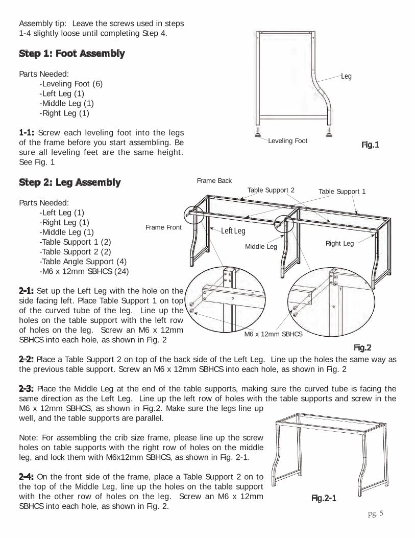
Assembly tip: Leave the screws used in steps 1-4 slightly loose until completing Step 4. Step 1: Foot Assembly
Parts Needed: -Leveling Foot (6) -Left Leg (1) -Middle Leg (1) -Right Leg (1)
1-1: Screw each leveling foot into the legs of the frame before you start assembling. Be sure all leveling feet are the same height. See Fig. 1
Step 2: Leg Assembly
Parts Needed: -Left Leg (1) -Right Leg (1) -Middle Leg (1) -Table Support 1 (2) -Table Support 2 (2) -Table Angle Support (4) -M6 x 12mm SBHCS (24)
2-1: Set up the Left Leg with the hole on the side facing left. Place Table Support 1 on top of the curved tube of the leg. Line up the holes on the table support with the left row of holes on the leg. Screw an M6 x 12mm SBHCS into each hole, as shown in Fig. 2
2-2: Place a Table Support 2 on top of the back side of the Left Leg. Line up the holes the same way as the previous table support. Screw an M6 x 12mm SBHCS into each hole, as shown in Fig. 2
2-3: Place the Middle Leg at the end of the table supports, making sure the curved tube is facing the same direction as the Left Leg. Line up the left row of holes with the table supports and screw in the M6 x 12mm SBHCS, as shown in Fig.2. Make sure the legs line up well, and the table supports are parallel.
Note: For assembling the crib size frame, please line up the screw holes on table supports with the right row of holes on the middle leg, and lock them with M6x12mm SBHCS, as shown in Fig. 2-1.
2-4: On the front side of the frame, place a Table Support 2 on to the top of the Middle Leg, line up the holes on the table support with the other row of holes on the leg. Screw an M6 x 12mm SBHCS into each hole, as shown in Fig. 2.
Fig.1
Leg
Leveling Foot
Frame Front
Right Leg
Fig.2
Left Leg
Table Support 1Table Support 2
M6 x 12mm SBHCS
Middle Leg
Frame Back
Fig.2-1

pg. 6
2-5: Place a Table Support 1 on to the top of the back side of the Middle Leg. Line up the holes and screw an M6 x 12mm SBHCS into each hole, as shown in Fig.2.
2-6: Place the Right Leg at the end of the unfixedtablesupports,orientedthethesamedirection as the Left and Middle Legs. Line up the right row of holes on the leg with the holes on the table supports, Screw an M6 x 12mm SBHCS into each hole, as shown in Fig.2.
2-7: Place a Table Angle Support at a 45 degree angle on the front top corners and back top corners of the frame on the outside. Line up the holes on the angle support with one hole on the front side of the leg tube, and one hole on the table support. Screw an M6 x 12mm SBHCS into each hole, as shown in Fig. 2-2.
Note: Attach the Table Angle Support to the middle leg for the crib size, as shown in Fig 2-3.
Step 3: Table Brace Assembly
Parts Needed: -Table Brace (4) -M5 x 10mm SCHCS (8)
3-1: Attach each Table Brace to the Table Supports by aligning the holes on the two ends of the table brace with the flat side facing up, screwing in the (8)-M5 x 10mm SCHCS, as shown in Fig. 3.Perform the same step with table braces for crib size, only 2 table braces will be used on a crib size frame, as shown in Fig. 3-1.
Note: Be sure the table braces are parallel to the legs.
Step 4: Frame End Left & Right Assembly
Parts Needed: -Frame End Left (1) -Frame End Right (1) -M6 x 12mm SBHCS (8)
4-1: Put (1) Frame End Right to the right side of the Right Leg, align the 2 groups of screw holes with the screw holes on the leg and screw in (4) M6 x 12mm SBHCS.
Table BraceM5 x 10mm
SCHCS
Fig.3
Fig.2-3
Fig.3-1
Table Angle Support
M6 x 12mmSBHCS
Fig.2-2

pg. 7
4-2: Assemble the Frame End Left in the same way as Step 4-1 to the Left Leg, see Fig. 4. Assemble the two Frame Ends in the same way for the queen size frame and crib size frame, as shown in Fig. 4-1.
Step 5: Tracks Assembly
Parts Needed: -Short Angle Track Support (4) -Long Angle Track Support (2) -M6 x 12mm SBHCS (16) -Long Track (2)
5-1: Lay a Short Angle Track Support on a table support, aligning the holes in the track support with the holes on the table support. The sides without holes are on the outside of the frame, see Fig. 5.For a crib size, use only the long track supports, and assemble them the same way as king size frame.
5-2: Attach the Track support to the table support by screwing (2) M6 x 12mm SBHCS, see Fig. 5. For the crib size frame, use the Long Angle Track Support only and assemble the same as king size frame.
5-3: Repeat Step 5-2 with the Long Angle Track Support and the other Short Angle Track Support. Be sure they lie in a straight line. See Fig. 5.
5-4: Press the Long Track onto the Track Support by allowing the Track Support to be pinched tightly by the Long Track. Be sure the Track Support bottoms out on the Long Track. See Fig. 5-1.
5-6: Repeat through Steps 5-1 to 5-3 to
Short Angle Track Support
Short Angle Track Support
Long Angle Track Support
Fig.5
Fig.5-1
M6 x 12mm SBHCS
M6 x 12mm SBHCS
Frame End Right
Frame End Left
Fig.4
Fig.4-1

pg. 8
assemble the other side of the the track on crib size frame as well, see Fig. 5-3.
Note: If the track is not a straight line, loosen the screws, adjust the parts and then tighten them again.
Step 6: Rail Holder Bracket Assembly
Parts Needed: -M6 x 24mm Carriage Bolt (4) -3-Wing Knob(4) -Rail Holder Bracket Left (2) -Rail Holder Bracket Right(2) -Frame End Connector (4)
Note: The Left and Right Rail Holder Brackets are attached at the two long slots in the frame ends, the heights and distances between the rail holder brackets can be adjusted as needed.
6-1: Assemble a Frame End Connector onto the Frame End Left so that the screw hole in the middle of the Frame End Connector is in line with the slot in the middle of the Frame End Left.
6-2: Place the Rail Holder Bracket Left onto the Frame End Left. Make sure that the bracket is placed on the right direction, see Fig. 6.
6-3: Place a M6 x 24mm Carriage Bolt in the inside hole on the Frame End Left, followed by the frame End Connector, and then the Rail Holder Bracket. Lock the assmebly together with a 3-Wing Knob, see Fig. 6.
6-4: Assemble the other Rail Holder BracketLeftontotheFrameEndLeftthesamewayasfirstoneexceptlocatingthebracketattheendofthe frame end, where there is a screw hole, see Fig. 6.
6-5: Assemble the (2) Rail Holder Bracket Right on the other side of the frame by repeating the above steps once again. See Fig. 6. Assembly steps are the same for crib size frame, see Fig. 6-1.
Note: Be sure that all rail holder brackets are facing the correct direction as shown in the picture.
Step 7: Rails Assembly
Parts Needed:
Rail HolderBracket
Left
Rail Holder Bracket Right
M6 x 24mm Carriage Bolt
3-Wing Knob
Frame EndConnector Fig.6
Fig.6-1
Fig.5-3
pg. 9
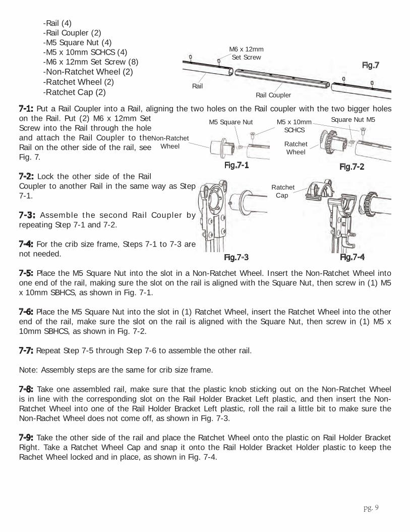
-Rail (4) -Rail Coupler (2) -M5 Square Nut (4) -M5 x 10mm SCHCS (4) -M6 x 12mm Set Screw (8) -Non-Ratchet Wheel (2) -Ratchet Wheel (2) -Ratchet Cap (2)
7-1: Put a Rail Coupler into a Rail, aligning the two holes on the Rail coupler with the two bigger holes on the Rail. Put (2) M6 x 12mm Set Screw into the Rail through the hole and attach the Rail Coupler to the Rail on the other side of the rail, see Fig. 7.
7-2: Lock the other side of the Rail Coupler to another Rail in the same way as Step 7-1.
7-3: Assemble the second Rail Coupler by repeating Step 7-1 and 7-2.
7-4: For the crib size frame, Steps 7-1 to 7-3 are not needed.
7-5: Place the M5 Square Nut into the slot in a Non-Ratchet Wheel. Insert the Non-Ratchet Wheel into one end of the rail, making sure the slot on the rail is aligned with the Square Nut, then screw in (1) M5 x 10mm SBHCS, as shown in Fig. 7-1.
7-6: Place the M5 Square Nut into the slot in (1) Ratchet Wheel, insert the Ratchet Wheel into the other end of the rail, make sure the slot on the rail is aligned with the Square Nut, then screw in (1) M5 x 10mm SBHCS, as shown in Fig. 7-2.
7-7: Repeat Step 7-5 through Step 7-6 to assemble the other rail.
Note: Assembly steps are the same for crib size frame.
7-8: Take one assembled rail, make sure that the plastic knob sticking out on the Non-Ratchet Wheel is in line with the corresponding slot on the Rail Holder Bracket Left plastic, and then insert the Non-Ratchet Wheel into one of the Rail Holder Bracket Left plastic, roll the rail a little bit to make sure the Non-Rachet Wheel does not come off, as shown in Fig. 7-3.
7-9: Take the other side of the rail and place the Ratchet Wheel onto the plastic on Rail Holder Bracket Right. Take a Ratchet Wheel Cap and snap it onto the Rail Holder Bracket Holder plastic to keep the Rachet Wheel locked and in place, as shown in Fig. 7-4.
M6 x 12mm Set Screw
RailRail Coupler
Fig.7
Ratchet Cap
Fig.7-4Fig.7-3
M5 x 10mm SCHCS
M5 Square Nut Square Nut M5
Ratchet Wheel
Non-Ratchet Wheel
Fig.7-2Fig.7-1

pg. 10
7-10: Repeat Steps 7-8 and 7-9 to assemble the other rail. see Fig. 7-5. For crib size frame, the assembly steps are the same, see Fig. 7-6.
Step 8: Top Plate Assembly
Parts Needed: -Top Plate (1) -Left Handle (1) -Right Handle (1) -Handle Brace (1) -M6 x 12mm SBHCS (4) -M6 x 40mm SBHCS (2)
8-1: Attach the Right Handle to the Top Plate by inserting an M6 x 12mm SBHCS through the handle and into the Top Plate, and tighten them up completely, as shown in Fig. 8.
8-2: Insert an M6 x 40mm SBHCS through the back of the handle and through the Top Plate, and tighten them up completely.
8-3: Repeat Steps 8-1 and 8-2 to assemble the left handle.
8-4: Attach the Handle Brace to the right and left handles by inserting (2) M6 x 12mm SBHCS, and tighten completely, as shown in Fig.8-1.
Step 9: Placing the Carriage
Parts Needed: -Top Plate Assembly (1) -Carriage (1) -Frame body Assembly (1)
9-1: Put the Top Plate Assembly on top of the Carriage. Make sure that the tracks are inserted in the grooves in the wheels. Place the whole assembly on the frame, see Fig.9.
M6 x 40mmSBHCS
Handle Bridge
Fig.8-1
Left Handle
Right Handle
M6 x 12mmSBHCS
Fig.8
Top Plate
Carriage
Fig.9
Fig.7-6Fig.7-5
pg. 11
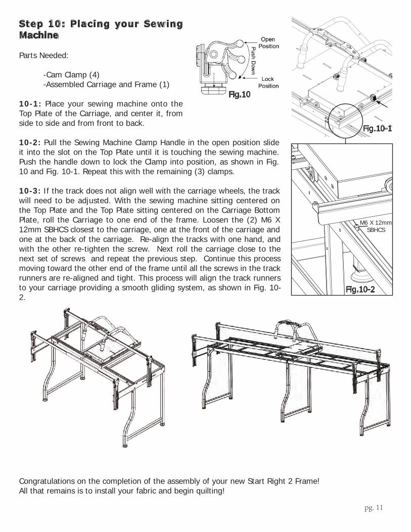
Step 10: Placing your Sewing Machine
Parts Needed:
-Cam Clamp (4) -Assembled Carriage and Frame (1)
10-1: Place your sewing machine onto the Top Plate of the Carriage, and center it, from side to side and from front to back.
10-2: Pull the Sewing Machine Clamp Handle in the open position slide it into the slot on the Top Plate until it is touching the sewing machine. Push the handle down to lock the Clamp into position, as shown in Fig. 10 and Fig. 10-1. Repeat this with the remaining (3) clamps.
10-3: If the track does not align well with the carriage wheels, the track will need to be adjusted. With the sewing machine sitting centered on the Top Plate and the Top Plate sitting centered on the Carriage Bottom Plate, roll the Carriage to one end of the frame. Loosen the (2) M6 X 12mm SBHCS closest to the carriage, one at the front of the carriage and one at the back of the carriage. Re-align the tracks with one hand, and with the other re-tighten the screw. Next roll the carriage close to the next set of screws and repeat the previous step. Continue this process moving toward the other end of the frame until all the screws in the track runners are re-aligned and tight. This process will align the track runners to your carriage providing a smooth gliding system, as shown in Fig. 10-2.
Congratulations on the completion of the assembly of your new Start Right 2 Frame!All that remains is to install your fabric and begin quilting!
Fig.10
Fig.10-1
M6 X 12mm SBHCS
Fig.10-2

pg. 12
Quilting Frame Fabric Installation
With the Grace Company’s, specially designed Fabri-Fast rails, installing your fabric is easier on this Frame than on any other frame. Each rail has a Fabri-Fast slot and accompanying tubing. These work together to make your fabric installation much easier and faster than using tape, tacks, or Velcro®.
Before you begin, please locate the plastic Fabri-Fast tool included in your shipment.
We recommend you begin with practice material allowing you to experiment with machine settings andstroke techniques.
NOTE: As you cut your fabric layers, we recommend making the quilt backing about 6-8” longer and2-4” wider than your top. This will allow for a little give in the backing, especially if using thicker batting.
Rail Rotation: It is important that each rail rotates the correct direction to apply tension toyour quilt layers correctly. Light tension is applied to your quilt fabric to remove wrinkles, and to allowthe fabric to be sewn together consistently throughout the entire quilt. The Ratchet Rail ends allowyou to limit the direction that each rail rotates. The ratchet can also be set to a neutral position bypulling the knob up and twisting it.
Installing Fabric Layers onto the Rails (Preview): Center your cloth lengthwise along the rail. Using Grace’s Fabri-FastTM System, take a piece of plastic tubing (cut to the appropriate length), and, holding your fabric to the slot (lining up the edge), press the tubing over the fabric and into the slot. Use the Fabri-Fast tool to press the rest of the tube and fabric in quickly and easily.
Methods of Installation: 1: Apply your fabric layers directly to the rails. 2: The recommended method of installation is to use Cloth Leaders. You may make and use Cloth Leaders, or purchase them. Using leaderclothsenableyoutofinishyourquiltcompletely,totheend,withouthavingtotakeyourquiltoffthe rails. See page 13 for instructions on how to make and use cloth leaders.
Making Cloth Leaders
1: First, select your cloth leader material. We recommend using a good quality muslin or similar fabric that has a good thread count. Be aware, however, that if the fabric is too thick,itmayprovemoredifficultgettingitinstalledintotherailslot.
pg. 13
2: Surge or hem your cloth leaders on all sides.
3: Make cloth leaders in the widths shown. (The recommended length is 105”, this length will accommodate any width of quilt that can be made on your Quilting Frame.)
4: Make a dashed line along the length of your leader about ½” in from the edge with a pen or marker. You will use this as a guide to help you insert your leader into the slot in straight line. (OPTIONAL: For a straighter cloth leader installation, some may consider it easier to make a hem and then push the tubing into the hem before installing it into the slot. If you wish to do this, create a hem on one end of each leader by folding over the fabric one inch (1”), and, using your foot pedal as a guide, stitching the fabric together 3/4” from the fold. This will leave about ¼” of fabric beyond the stitching. Leave the edges open on both ends. You may then slide your tubing into the hem, Fig. CL1-1).
5: Mark each cloth leader at the center (length-wise).
6: Mark (or baste) a straight line about ½” in from the opposite (non-hemed, or non-dashed) end of the leader. This will be the line to which you attach your fabric layer.
7: Center your cloth leader lengthwise along the rail. Using Grace’s Fabri-FastTM System, take a piece of plastic tubing (cut to the appropriate length), and, holding your cloth leader to the slot (lining up the dashed line), press the tubing over the leader and into the slot. Use the Fabri-Fast tool to press the rest of the tube and fabric in quickly and easily. (If you have made a hem, line up this hem w/ tubing over the slot and press it into the slot using the Fabri-Fast tool. 8: With Cloth Leaders in place, pin your Quilt Fabric to the Leaders, rather than attaching it directly to the Rails.
Installing Fabric Layers onto Rails
STEP 1: Quilt Backing to 2nd Rail
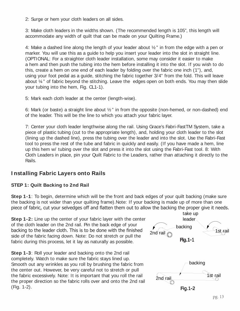
Step 1-1: To begin, determine which will be the front and back edges of your quilt backing (make sure the backing is not wider than your quilting frame).Note: If your backing is made up of more than one pieceoffabric,cutyourselvedgesoffandflattenthemouttoallowthebackingthepropergiveitneeds.
Step 1-2: Line up the center of your fabric layer with the center of the cloth leader on the 2nd rail. Pin the back edge of your backingtotheleadercloth.Thisistobedonewiththefinishedside of the fabric facing down. Note: Do not stretch or pull the fabric during this process, let it lay as naturally as possible.
Step 1-3: Roll your leader and backing onto the 2nd rail completely. Watch to make sure the fabric stays lined up. Smooth out any wrinkles as you roll by brushing the fabric from the center out. However, be very careful not to stretch or pull the fabric excessively. Note: It is important that you roll the rail the proper direction so the fabric rolls over and onto the 2nd rail (Fig. 1-2).
backing
take up leader
1st rail2nd rail
backing
1st rail2nd rail
Fig.1-1
Fig.1-2
pg. 14
Step 2: Attaching Your Quilt Layers to The Take-Up Rail
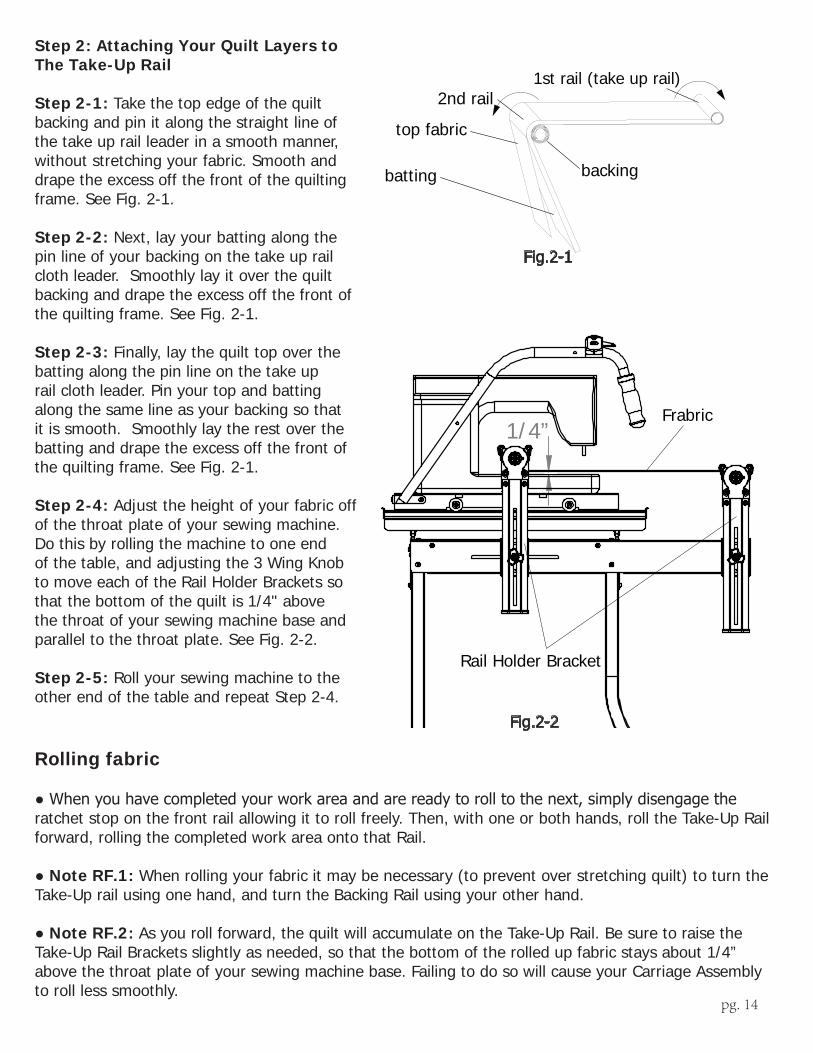
Step 2-1: Take the top edge of the quilt backing and pin it along the straight line of the take up rail leader in a smooth manner, without stretching your fabric. Smooth and drape the excess off the front of the quilting frame. See Fig. 2-1.
Step 2-2: Next, lay your batting along the pin line of your backing on the take up rail cloth leader. Smoothly lay it over the quilt backing and drape the excess off the front of the quilting frame. See Fig. 2-1.
Step 2-3: Finally, lay the quilt top over the batting along the pin line on the take up rail cloth leader. Pin your top and batting along the same line as your backing so that it is smooth. Smoothly lay the rest over the batting and drape the excess off the front of the quilting frame. See Fig. 2-1.
Step 2-4: Adjust the height of your fabric off of the throat plate of your sewing machine. Do this by rolling the machine to one end of the table, and adjusting the 3 Wing Knob to move each of the Rail Holder Brackets so that the bottom of the quilt is 1/4" above the throat of your sewing machine base and parallel to the throat plate. See Fig. 2-2.
Step 2-5: Roll your sewing machine to the other end of the table and repeat Step 2-4.
Rolling fabric
●Whenyouhavecompletedyourworkareaandarereadytorolltothenext,simplydisengagetheratchet stop on the front rail allowing it to roll freely. Then, with one or both hands, roll the Take-Up Rail forward, rolling the completed work area onto that Rail.
●Note RF.1: When rolling your fabric it may be necessary (to prevent over stretching quilt) to turn the Take-Up rail using one hand, and turn the Backing Rail using your other hand.
●Note RF.2: As you roll forward, the quilt will accumulate on the Take-Up Rail. Be sure to raise the Take-Up Rail Brackets slightly as needed, so that the bottom of the rolled up fabric stays about 1/4” above the throat plate of your sewing machine base. Failing to do so will cause your Carriage Assembly to roll less smoothly.
Step 1: Install quilt backing to 2nd rail and roll up.Step 2:Step 3:Step 4:
Attach quilt backing to take up rail. Attach batting to take up rail. Attach quilt top to take up rail.
backing
top fabric
batting
2nd rail1st rail (take up rail)
Fig.2-1
1/4”
Rail Holder Bracket
Frabric
Fig.2-2
pg. 15
Quilt Block Size Considerations
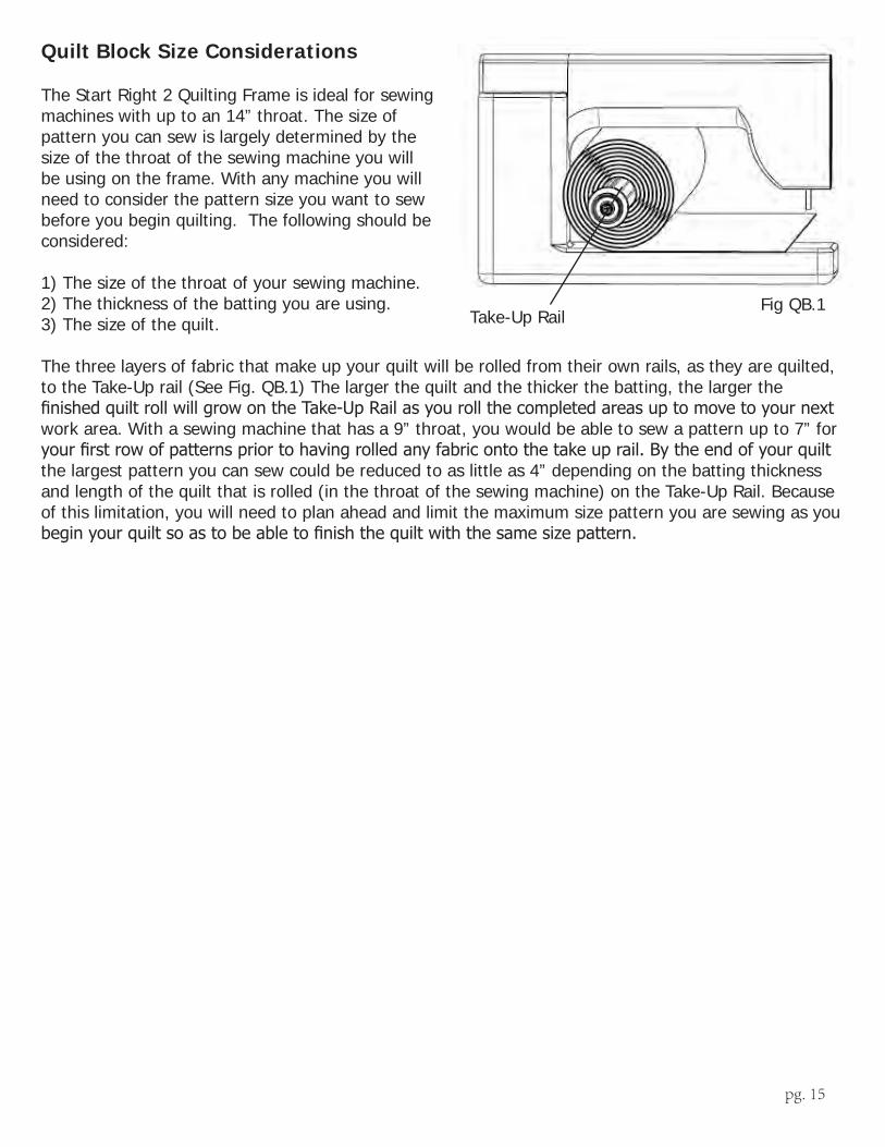
The Start Right 2 Quilting Frame is ideal for sewing machines with up to an 14” throat. The size of pattern you can sew is largely determined by the size of the throat of the sewing machine you will be using on the frame. With any machine you will need to consider the pattern size you want to sew before you begin quilting. The following should be considered:
1) The size of the throat of your sewing machine. 2) The thickness of the batting you are using. 3) The size of the quilt.
The three layers of fabric that make up your quilt will be rolled from their own rails, as they are quilted, to the Take-Up rail (See Fig. QB.1) The larger the quilt and the thicker the batting, the larger the finishedquiltrollwillgrowontheTake-UpRailasyourollthecompletedareasuptomovetoyournextwork area. With a sewing machine that has a 9” throat, you would be able to sew a pattern up to 7” for yourfirstrowofpatternspriortohavingrolledanyfabricontothetakeuprail.Bytheendofyourquiltthe largest pattern you can sew could be reduced to as little as 4” depending on the batting thickness and length of the quilt that is rolled (in the throat of the sewing machine) on the Take-Up Rail. Because of this limitation, you will need to plan ahead and limit the maximum size pattern you are sewing as you beginyourquiltsoastobeabletofinishthequiltwiththesamesizepattern.
Take-Up RailFig QB.1

pg. 16
Bungee ClampsThe Bungee Clamps provide excellent and even side tension for your quilts, all the way to the edges of your quilting frame. Grace Bungee Clamps are designed for easy attachment and removal, and have a slim profile that lets you get right up close with your sewing machine.
Start-Right Cloth LeadersStart-Right Cloth Leaders save time during your project and help you attach your fabric
to you frame easily and accurately. The included three cloth leaders are printed with precise guide marks and pin lines.
SureStitch Stitch RegulatorThe Grace SureStitch is both a stitch regulator and constant stitch speed control. As you speed up
and slow down in Stitch Regulation mode, so will your machine, keeping all of your stitches the same length. You can also use the SureStitch for a constant speed that you can adjust with the push of a button.
Quilting AccessoriesThe following accessories are available for your new SR-2 Machine Quilting Frame.
Each is designed to make your quilting projects easier and even more beautiful.They can all be purchased through your GraceFrame dealer, or directly from The Grace Company.
www.graceframe.com 1-800-264-0644
Table-Top InsertsTable-top inserts add more working area to your frame. Use them for the Plastic Pattern Perfect, or as a place to put panto-graphs to be traced with the Gracie Laser.
STan

pg. 17
Gracie LaserPattern tracing is easier than ever before with the Gracie Laser.
• Attaches to the front or back of your frame’s carriage!• Swivel and lock the stylus at any angle• Battery powered, no cords to get in the way!• Comes with four different laser tips to control laser size
Plastic Pattern Perfect Additional Templates6 additional patterns to choose from,with more being added all the time! These additional patterns work with the stylus from the basic Plastic Pattern Perfects. They come in a set of 2 or a set of 6 for your whole frame.
Goose-Neck LampThe Grace Goose-Neck Lamp is the perfect way to light up your projects!
• Brite-White Bulb included• White light for viewing colors accurately• Mounts to the left or right side of the carriage• No assembly required
www.graceframe.com 1-800-264-0644
Plastic Pattern PerfectFor perfect patterns every time, use the Plastic Pattern Perfect! The stylus attaches right to your carriage, and then guides your machine through the pattern templates as you move the carriage.*Note: Table-top inserts must be installed to use these templates.
Order online, or give us a call at:
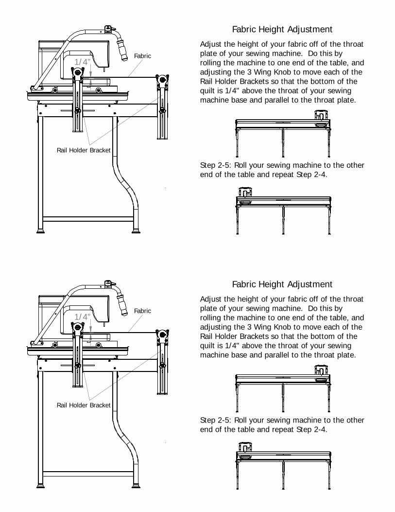
1/4”
Adjust the height of your fabric off of the throat plate of your sewing machine. Do this by rolling the machine to one end of the table, and adjusting the 3 Wing Knob to move each of the Rail Holder Brackets so that the bottom of the quilt is 1/4" above the throat of your sewing machine base and parallel to the throat plate.
Step 2-5: Roll your sewing machine to the other end of the table and repeat Step 2-4.
Fabric Height Adjustment
Rail Holder Bracket
Fabric

Start Right Frame Addendum
Ratchet Stop-
Tools Needed: 1- Flat Head Screw Driver
To Replace the Ratchet, take off the Cover Plate by inserting a Flat Head Screw Driver into the side of the Cover Plate and pop off the Cover Plate, as shown in Fig. RS-1. Pull out the Ratchet Stop, and the Plastic Ratchet Pin, and insert the new Ratchet. Reinsert the pieces into the Ratchet Fixture as shown in RS-2.
Ratchet Pin
Cover Plate
Ratchet Stop
Fig. RS-2
Spring
Flat Head Screw Driver
Fig. RS-1