Embed Size (px)
Citation preview
Assembly instructions of an electrofusion entry boot
for single and double wall systems
ModelSEBE
INSTALLATIONS TOOLS SHOWN ON PAGE 6

II
1
Fig.1
Fig.2
CENTRE
Fig.3
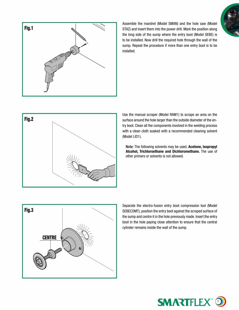
Assemble the mandrel (Model SMAN) and the hole saw (Model STAZ) and insert them into the power drill. Mark the position along the long side of the sump where the entry boot (Model SEBE) is to be installed. Now drill the required hole through the wall of the sump. Repeat the procedure if more than one entry boot is to be installed.
Use the manual scraper (Model RAM1) to scrape an area on the surface around the hole larger than the outside diameter of the en-try boot. Clean all the components involved in the welding process with a clean cloth soaked with a recommended cleaning solvent (Model LID1).
Note: The following solvents may be used, Acetone, Isopropyl Alcohol, Trichloroethane and Dichloromethane. The use of other primers or solvents is not allowed.
Separate the electro-fusion entry boot compression tool (Model SEBECOMT), position the entry boot against the scraped surface of the sump and centre it in the hole previously made. Insert the entry boot in the hole paying close attention to ensure that the central cylinder remains inside the wall of the sump.
2
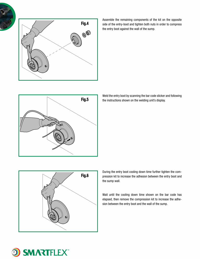
Fig.4Assemble the remaining components of the kit on the opposite side of the entry-boot and tighten both nuts in order to compress the entry boot against the wall of the sump.
Fig.6
Fig.5Weld the entry boot by scanning the bar code sticker and following the instructions shown on the welding unit’s display.
During the entry boot cooling down time further tighten the com-pression kit to increase the adhesion between the entry boot and the sump wall.
Wait until the cooling down time shown on the bar code has elapsed, then remove the compression kit to increase the adhe-sion between the entry boot and the wall of the sump.
3
Fig.7
Fig.8
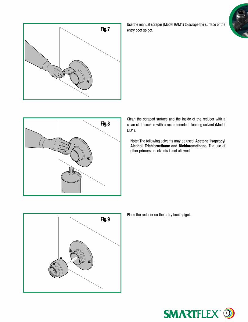
Use the manual scraper (Model RAM1) to scrape the surface of the entry boot spigot.
Clean the scraped surface and the inside of the reducer with a clean cloth soaked with a recommended cleaning solvent (Model LID1).
Note: The following solvents may be used, Acetone, Isopropyl Alcohol, Trichloroethane and Dichloromethane. The use of other primers or solvents is not allowed.
Fig.9Place the reducer on the entry boot spigot.
4
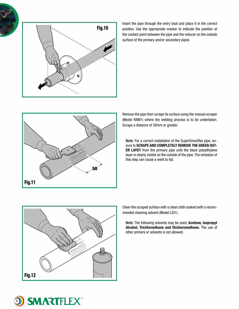
Fig.10
50
Fig.11
Insert the pipe through the entry boot and place it in the correct position. Use the appropriate marker to indicate the position at the contact point between the pipe and the reducer on the outside surface of the primary and/or secondary pipes.
Remove the pipe then scrape its surface using the manual scraper (Model RAM1) where the welding process is to be undertaken. Scrape a distance of 50mm or greater.
Note: For a correct installation of the SuperSmartlfex pipe, en-sure to SCRAPE AND COMPLETELY REMOVE THE GREEN OUT-ER LAYER from the primary pipe until the black polyethylene layer is clearly visible on the outside of the pipe. The omission of this step can cause a weld to fail.
Fig.12
Clean the scraped surface with a clean cloth soaked with a recom-mended cleaning solvent (Model LID1).
Note: The following solvents may be used, Acetone, Isopropyl Alcohol, Trichloroethane and Dichloromethane. The use of other primers or solvents is not allowed.
5
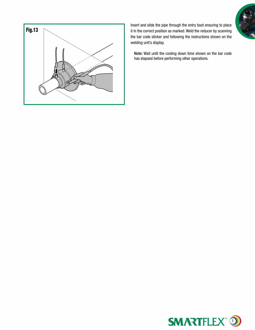
Fig.13Insert and slide the pipe through the entry boot ensuring to place it in the correct position as marked. Weld the reducer by scanning the bar code sticker and following the instructions shown on the welding unit’s display.
Note: Wait until the cooling down time shown on the bar code has elapsed before performing other operations.
6
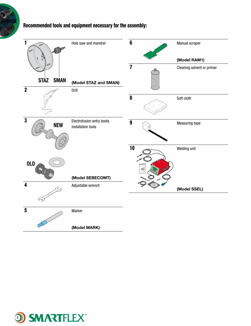
Recommended tools and equipment necessary for the assembly:
1
SMANSTAZ
Hole saw and mandrel
(Model STAZ and SMAN)
2 Drill
3 Electrofusion entry boots installation tools
(Model SEBECOMT)
4 Adjustable wrench
5 Marker
(Model MARK)
6 Manual scraper
(Model RAM1)
7 Cleaning solvent or primer
8 Soft cloth
9 Measuring tape
10 Welding unit
(Model SSEL)
NEW
OLD

7

8
This document is property of NUPIGECO S.p.a, no part of it may be copied or reproduced, with-out prior written consent from NUPIGECO. NUPIGECO S.p.a reserves the right to make the op-portune technical modifications without notice. NUPIGECO S.p.a doesn’t guarantee the correct operation of the system in case the information contained in this document are not followed.
NUPIGECO SpAVia dell’Artigianato, 13 - 40023 Castel Guelfo di Bologna - Italy Phone (39) 0331 344211 - Fax (39) 0542 670851E-Mail: [email protected] - Web Site: www.nupigeco.com
NUPI Americas, Inc.1511 Superior Way, Houston, TX 77039 Phone (281) 590 4471 - Fax (281) 590 5268E-Mail: [email protected] - Web Site: www.nupiamericas.com


![Coupled thermomechanical analisys of electrofusion ...pages.mscsoftware.com/rs/mscsoftware/images/coes_october6[1].pdfCoupled thermomechanical analisys of electrofusion fittings](https://img.pdfslide.us/doc/110x75/5adcf8f57f8b9a9d4d8c7bc7/coupled-thermomechanical-analisys-of-electrofusion-pages-1pdfcoupled-thermomechanical.jpg)