Embed Size (px)
Citation preview

Assembly Instructions
english100-910-042-01
22.03.10
FANCREEL

1
Introduction / Table of Contents
IntroductionWe are delighted that you have decided to purchase a MEMMINGER-IRO product. Please note that the more familiar you are with the product, the better the results achieved with it will be.
Please read these instructions through carefully therefore before putting the product into service. They contain impor-tant information and advice that must be observed when using the equipment.
Table of ContentsIntroduction ................................................................................................................................................................ 1Table of Contents ...................................................................................................................................................... 1Important Notes ......................................................................................................................................................... 2Symbol definition ......................................................................................................................................................... 2General notes .............................................................................................................................................................. 2
Function ..................................................................................................................................................................... 2Models ........................................................................................................................................................................ 2
Assembly.................................................................................................................................................................... 3Assembly the creel sections ........................................................................................................................................ 3Assembly the stabiliser ring ........................................................................................................................................ 4Assembly the creel sections ........................................................................................................................................ 5Assembly the slip ring box and the pivot rod ............................................................................................................... 6Assembly and connecting the fans .............................................................................................................................. 7Assembly tube support ................................................................................................................................................ 8Assembly the yarn tubes ............................................................................................................................................. 9Assembly the tube holders at machine side .............................................................................................................. 10Assembly the Air-Jet .................................................................................................................................................. 10
Electrical Connection .............................................................................................................................................. 11
Spare Parts List ....................................................................................................................................................... 12
Technical Data ......................................................................................................................................................... 15
Declaration of incorporation and conformity ....................................................................................................... 16
2
Important Notes / Function / Models
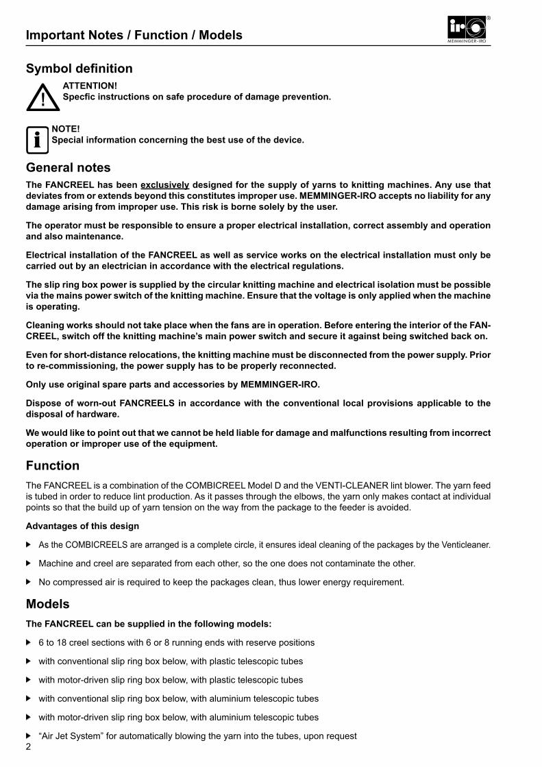
Symbol definitionATTENTION!Specfic instructions on safe procedure of damage prevention.
NOTE!Special information concerning the best use of the device.
General notesThe FANCREEL has been exclusively designed for the supply of yarns to knitting machines. Any use that deviates from or extends beyond this constitutes improper use. MEMMINGER-IRO accepts no liability for any damage arising from improper use. This risk is borne solely by the user.
The operator must be responsible to ensure a proper electrical installation, correct assembly and operation and also maintenance.
Electrical installation of the FANCREEL as well as service works on the electrical installation must only be carried out by an electrician in accordance with the electrical regulations.
The slip ring box power is supplied by the circular knitting machine and electrical isolation must be possible via the mains power switch of the knitting machine. Ensure that the voltage is only applied when the machine is operating.
Cleaning works should not take place when the fans are in operation. Before entering the interior of the FAN-CREEL, switch off the knitting machine’s main power switch and secure it against being switched back on.
Even for short-distance relocations, the knitting machine must be disconnected from the power supply. Prior to re-commissioning, the power supply has to be properly reconnected.
Only use original spare parts and accessories by MEMMINGER-IRO.
Dispose of worn-out FANCREELS in accordance with the conventional local provisions applicable to the disposal of hardware.
We would like to point out that we cannot be held liable for damage and malfunctions resulting from incorrect operation or improper use of the equipment.
FunctionThe FANCREEL is a combination of the COMBICREEL Model D and the VENTI-CLEANER lint blower. The yarn feed is tubed in order to reduce lint production. As it passes through the elbows, the yarn only makes contact at individual points so that the build up of yarn tension on the way from the package to the feeder is avoided.
Advantages of this design
As the COMBICREELS are arranged is a complete circle, it ensures ideal cleaning of the packages by the Venti cleaner.
Machine and creel are separated from each other, so the one does not contaminate the other.
No compressed air is required to keep the packages clean, thus lower energy requirement.
ModelsThe FANCREEL can be supplied in the following models:
6 to 18 creel sections with 6 or 8 running ends with reserve positions
with conventional slip ring box below, with plastic telescopic tubes
with motor-driven slip ring box below, with plastic telescopic tubes
with conventional slip ring box below, with aluminium telescopic tubes
with motor-driven slip ring box below, with aluminium telescopic tubes
“Air Jet System” for automatically blowing the yarn into the tubes, upon request
!
i
3
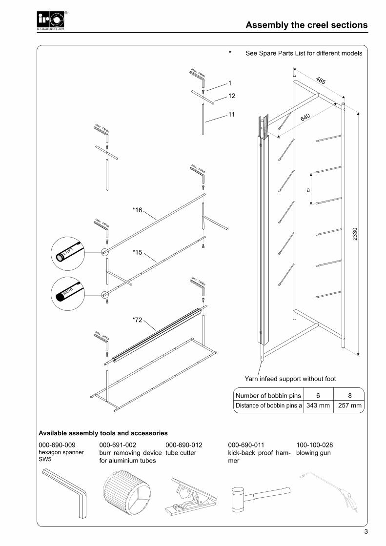
Assembly the creel sections
* See Spare Parts List for different models
Number of bobbin pins 6 8Distance of bobbin pins a 343 mm 257 mm
Yarn infeed support without foot
12
11
*16
*15
*72
Available assembly tools and accessories
000-690-012tube cutter
000-691-002burr removing device for aluminium tubes
100-100-028blowing gun
000-690-011kick-back proof ham-mer
000-690-009hexagon spannerSW5
1

4
Assembly the stabiliser ring
With 6 to 8 sections:1 stabiliser ring
With 9 to 18 sections:2 to 3 stabiliser partrings
Fit the support bolt vertically and centred.Adjust the feet so that the support bolt 351, makes contact with the floor.
9
*71
736
68
69*67
9
*70
7
3
69
*67
68
* See Spare Parts List for different models

5
Assembly the creel sections
With 6 to 8 sections:1 stabiliser ring
With 9 to 18 sections:2 to 3 stabiliser partrings
*14
13
6
* See Spare Parts List for different models

6
Assembly the slip ring box and the pivot rod
* See Spare Parts List for different models
align vertically
Spare Parts ListSlip ring box010-930-003
7
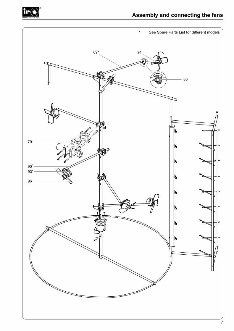
Assembly and connecting the fans
* See Spare Parts List for different models

8
Assembly tube support
NOTE!Various tube support models:for plastic tubes, 6 to 11 sections: 3 x item 101for plastic tubes, 12 to 18 sections: 6 x item 101for aluminium tubes, 6 to 11 sections 2 x item 101for aluminium tubes, 12 to 18 sections: 4 x item 101
4 3 6 100 101 *99 4 2
18
17
5
97
98
i
* See Spare Parts List for different models

9
Assembly the yarn tubes
plastic tubes aluminium tubes
aluminium tubes S
adjust height of tube conduct glue on system numbers
26 28
* 19
* 20 27
22* 29
* 30
27
24*29
*30
* 19* 20
26
27
24* 29
* 30
* 19
* 19
23
26
31
32
* 53
* 21
* 25
* 23

10
tube holders at machine side
Air-Jetmax. 4bar
3 mm
25 mm
33
34843738
39
40
41
42
3534
3637
3637
44
39
43
34
36
39
45
46 47
48
49
5051
52
55
58
59
60
61
62
63
57
64
54
Assembly the tube holders at machine side and the Air-Jet
65
56
66

11
Electrical Connection
ATTENTION!Work on the electrical system may only be carried out by a qualified electrician in accordance with the relevant electrotechnical regulations.
The power supply to the slip ring box is taken from the circular knitting machine after the main switch. It must therefore be live only when the machine is running.
To prevent electrical shock, the power connection plug must not be mounted in an easily accessible position.
The safety latch on the plug must be kept closed whilst the FANCREEL is in operation.
The plug connection must not be disconnected whilst live.
When switching on, the housing covers on the power supply section must be closed.
Connect the slip ring box on the machine as shown in the wiring diagram.
All fan leads are taken through the central rod into the slip ring box and connected as shown in the wiring dia-gram.
Close the cover on the slip ring box when all the leads have been connected.
!
bl = bluebr = brownschw = blackge-gr = yellow-green
Fan connection
Connection to the knitting machine.Must not be live when machine is not running.
Plug connection
brbl
ge-gr ge-gr
L1 brPE ge-grN bl
12
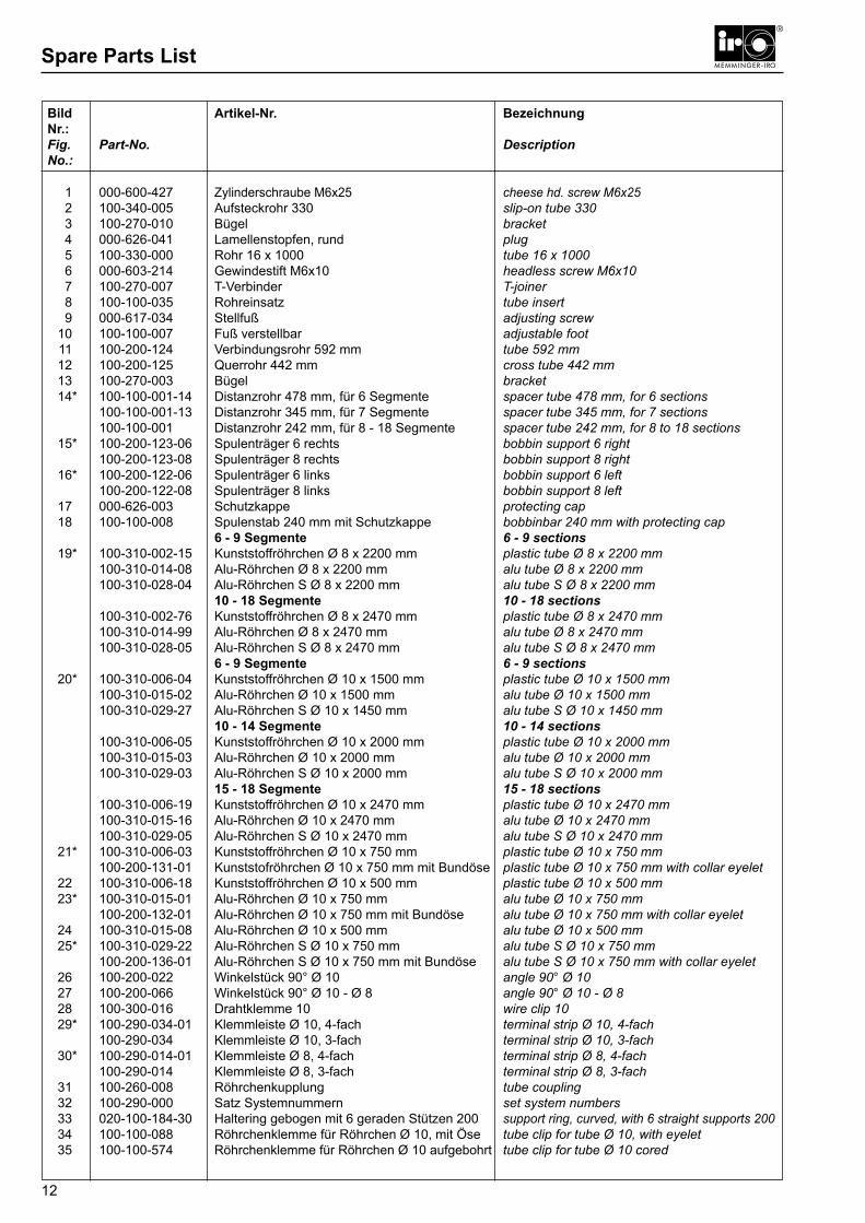
Spare Parts List
Bild Artikel-Nr. BezeichnungNr.:Fig. Part-No. DescriptionNo.:
1 000-600-427 Zylinderschraube M6x25 cheese hd. screw M6x25 2 100-340-005 Aufsteckrohr 330 slip-on tube 330 3 100-270-010 Bügel bracket 4 000-626-041 Lamellenstopfen, rund plug 5 100-330-000 Rohr 16 x 1000 tube 16 x 1000 6 000-603-214 Gewindestift M6x10 headless screw M6x10 7 100-270-007 T-Verbinder T-joiner 8 100-100-035 Rohreinsatz tube insert 9 000-617-034 Stellfuß adjusting screw 10 100-100-007 Fuß verstellbar adjustable foot 11 100-200-124 Verbindungsrohr 592 mm tube 592 mm 12 100-200-125 Querrohr 442 mm cross tube 442 mm 13 100-270-003 Bügel bracket 14* 100-100-001-14 Distanzrohr 478 mm, für 6 Segmente spacer tube 478 mm, for 6 sections 100-100-001-13 Distanzrohr 345 mm, für 7 Segmente spacer tube 345 mm, for 7 sections 100-100-001 Distanzrohr 242 mm, für 8 - 18 Segmente spacer tube 242 mm, for 8 to 18 sections 15* 100-200-123-06 Spulenträger 6 rechts bobbin support 6 right 100-200-123-08 Spulenträger 8 rechts bobbin support 8 right 16* 100-200-122-06 Spulenträger 6 links bobbin support 6 left 100-200-122-08 Spulenträger 8 links bobbin support 8 left 17 000-626-003 Schutzkappe protecting cap 18 100-100-008 Spulenstab 240 mm mit Schutzkappe bobbinbar 240 mm with protecting cap 6 - 9 Segmente 6 - 9 sections 19* 100-310-002-15 Kunststoffröhrchen Ø 8 x 2200 mm plastic tube Ø 8 x 2200 mm 100-310-014-08 Alu-Röhrchen Ø 8 x 2200 mm alu tube Ø 8 x 2200 mm 100-310-028-04 Alu-Röhrchen S Ø 8 x 2200 mm alu tube S Ø 8 x 2200 mm 10 - 18 Segmente 10 - 18 sections 100-310-002-76 Kunststoffröhrchen Ø 8 x 2470 mm plastic tube Ø 8 x 2470 mm 100-310-014-99 Alu-Röhrchen Ø 8 x 2470 mm alu tube Ø 8 x 2470 mm 100-310-028-05 Alu-Röhrchen S Ø 8 x 2470 mm alu tube S Ø 8 x 2470 mm 6 - 9 Segmente 6 - 9 sections 20* 100-310-006-04 Kunststoffröhrchen Ø 10 x 1500 mm plastic tube Ø 10 x 1500 mm 100-310-015-02 Alu-Röhrchen Ø 10 x 1500 mm alu tube Ø 10 x 1500 mm 100-310-029-27 Alu-Röhrchen S Ø 10 x 1450 mm alu tube S Ø 10 x 1450 mm 10 - 14 Segmente 10 - 14 sections 100-310-006-05 Kunststoffröhrchen Ø 10 x 2000 mm plastic tube Ø 10 x 2000 mm 100-310-015-03 Alu-Röhrchen Ø 10 x 2000 mm alu tube Ø 10 x 2000 mm 100-310-029-03 Alu-Röhrchen S Ø 10 x 2000 mm alu tube S Ø 10 x 2000 mm 15 - 18 Segmente 15 - 18 sections 100-310-006-19 Kunststoffröhrchen Ø 10 x 2470 mm plastic tube Ø 10 x 2470 mm 100-310-015-16 Alu-Röhrchen Ø 10 x 2470 mm alu tube Ø 10 x 2470 mm 100-310-029-05 Alu-Röhrchen S Ø 10 x 2470 mm alu tube S Ø 10 x 2470 mm 21* 100-310-006-03 Kunststoffröhrchen Ø 10 x 750 mm plastic tube Ø 10 x 750 mm 100-200-131-01 Kunststofröhrchen Ø 10 x 750 mm mit Bundöse plastic tube Ø 10 x 750 mm with collar eyelet 22 100-310-006-18 Kunststoffröhrchen Ø 10 x 500 mm plastic tube Ø 10 x 500 mm 23* 100-310-015-01 Alu-Röhrchen Ø 10 x 750 mm alu tube Ø 10 x 750 mm 100-200-132-01 Alu-Röhrchen Ø 10 x 750 mm mit Bundöse alu tube Ø 10 x 750 mm with collar eyelet 24 100-310-015-08 Alu-Röhrchen Ø 10 x 500 mm alu tube Ø 10 x 500 mm 25* 100-310-029-22 Alu-Röhrchen S Ø 10 x 750 mm alu tube S Ø 10 x 750 mm 100-200-136-01 Alu-Röhrchen S Ø 10 x 750 mm mit Bundöse alu tube S Ø 10 x 750 mm with collar eyelet 26 100-200-022 Winkelstück 90° Ø 10 angle 90° Ø 10 27 100-200-066 Winkelstück 90° Ø 10 - Ø 8 angle 90° Ø 10 - Ø 8 28 100-300-016 Drahtklemme 10 wire clip 10 29* 100-290-034-01 Klemmleiste Ø 10, 4-fach terminal strip Ø 10, 4-fach 100-290-034 Klemmleiste Ø 10, 3-fach terminal strip Ø 10, 3-fach 30* 100-290-014-01 Klemmleiste Ø 8, 4-fach terminal strip Ø 8, 4-fach 100-290-014 Klemmleiste Ø 8, 3-fach terminal strip Ø 8, 3-fach 31 100-260-008 Röhrchenkupplung tube coupling 32 100-290-000 Satz Systemnummern set system numbers 33 020-100-184-30 Haltering gebogen mit 6 geraden Stützen 200 support ring, curved, with 6 straight supports 200 34 100-100-088 Röhrchenklemme für Röhrchen Ø 10, mit Öse tube clip for tube Ø 10, with eyelet 35 100-100-574 Röhrchenklemme für Röhrchen Ø 10 aufgebohrt tube clip for tube Ø 10 cored

13
Spare Parts List
Bild Artikel-Nr. BezeichnungNr.:Fig. Part-No. DescriptionNo.:
36 020-100-183-01 Befestigungsring, gebogen, 8 x Ø nach fixing ring, curved, 8 x Ø according to Angabe, 2-geteilt, mit 2 Verbindern specification divided, with two connectors 37 020-100-189 Ringverbinder Ø 8 mit Gewindestift ring connector Ø 8 with headless screw 38 100-310-000-17 Spulenstab 200 bobbin bar 200 39 020-100-420 Ringklammer mit Gewindestiften ring clamp with headless screws 40 020-100-184-40 Haltering gebogen, 2-geteilte mit 6 gebogenen support-ring, bended, 2 pieces, with 6 curved Stützen 260, Klemmstück und Ringverbindern supports 260, clamps and ring connectors 41 020-100-047 T-Stück T-piece 42 020-310-003 Stütze gebogen 8 x 260 support, curved, 8 x 260 mm 43 020-100-184-73 Doppel-Haltering gebogen mit 6 geraden Stützen double support ring, curved, with 6 straight supports 44 100-310-000-01 Stab 480 bar 480 45 020-100-418 Ringhalter ring holder 46 000-626-036 Übersteckfuß ID19 schwarz foot ID 19 black 47* 020-100-240-xx Absteller Ring (Ø abhängig vom Fournisseurring) stop motion ring (diam. dependent on feeder ring) 48 020-100-422 Halter mit Schraube und Mutter holder with screw and nut 49 022-280-000 Spannrollenbolzen 420 shaft 420 for jockey pulley 50 020-100-414 Winkel mit Schrauben und Muttern angle with screws and nuts 51 022-100-060-01 Spannrollenbolzen 2L140 mit Halter shaft 2 L140 for jockey pulley 2 with mounting block 52 100-200-130 Röhrchenclip Ø 10 für Ring 25 x 3 tube clip Ø 10 for ring 25 x 3 53* 001-100-133 Umbausatz Einlaufarm mit Röhrchenklammer conversion set input arm with tube clip für MPF 10-K for MPF 10-K 001-100-133-01 Umbausatz Einlaufarm mit Röhrchenklammer conversion set input arm with tube clip für MPF 20-K for MPF 20-K 001-100-133-02 Umbausatz Einlaufarm mit Röhrchenklammer conversion set input arm with tube clip für MPF 30-K und MPF 20-KF for MPF 30-K and MPF 20-KF 54 001-260-050 Röhrchenhalter Ø 10 tube holder Ø 10 55 000-655-008-02 Filterdruckregler R 1/4'' mit automatischem filter pressure regulator R1/4" with automatic Kondensatablass condensate drain 56 000-660-019 Kunststoffschlauch plastic hose 8 x 6 57 000-661-001 Schlauchband mit Schraube 8-12 hose strap with screw 58 000-660-016 Gewebeschlauch D11 x 2,5 LW6 braided hose 59 100-270-050 Halter gebogen, für Filterdruckregler holder, curved 60 100-270-003 Bügel bracket 61 000-600-516 Zylinderschraube M6x16 cheese head screw 62 000-659-043 Verschlusskappe 8/6 locking cap 63 000-659-044 T-Reduzierstutzen T-reducing socket 64 100-100-148 Filterdruckregler R 1/4'' (Air-Jet) an Rundrohr filter pressure regulator R 1/4" for round pipe incl. inkl. Befestigung, Zuleitung und Verschlusskappe fastening, feed pipe and locking cap 65 100-100-629 Air-Jet Ventilkörper valve body for Air-Jet 66 100-100-630 T-Anschluss Air-Jet T-connector Air-Jet 67* 100-340-004-08 Rohr Ø 25 x 608 mm, für 6, 7, 8 tube Ø 25 x 608 mm, for 6, 7, 8 100-340-004-09 Rohr Ø 25 x 836 mm, für 9 tube Ø 25 x 836 mm, for 9 100-340-004-10 Rohr Ø 25 x 1070 mm, für 10 tube Ø 25 x 1070 mm, for 10 100-340-004-11 Rohr Ø 25 x 1295 mm, für 11 tube Ø 25 x 1295 mm, for 11 100-340-004-12 Rohr Ø 25 x 1522 mm, für 12 tube Ø 25 x 1522 mm, for 12 100-340-004-13 Rohr Ø 25 x 1750 mm, für 13 tube Ø 25 x 1750 mm, for 13 100-340-004-04 Rohr Ø 25 x 2000 mm, für 14 tube Ø 25 x 2000 mm, for 14 100-340-004-15 Rohr Ø 25 x 2140 mm, für 15 tube Ø 25 x 2140 mm, for 15 100-340-004-16 Rohr Ø 25 x 2440 mm, für 16 tube Ø 25 x 2440 mm, for 16 100-100-600-17 Rohrset 2750 mm, für Stabilisierungsring 17 tubeset 2750 mm, for 17 sections 100-100-600-18 Rohrset 2980 mm, für Stabilisierungsring 18 tubeset 2980 mm, for 18 sections 68 100-360-003-01 Aufnahmebolzen 35 x 400 receiving bolt 35 x 400 69 000-603-231 Gewindestift M6x20 headless screw M6x20 70* 100-330-008 Stabilisierungsring Ø 560, für 6 Segmente stabilizing ring Ø 560, for 6 sections 100-330-008-01 Stabilisierungsring Ø 560, für 7 Segmente stabilizing ring Ø 560, for 7 sections 100-330-004-02 Stabilisierungsring für 8 Segmente stabilizing ring for 8 sections 71* 100-330-011-09 Stabilisierungsring für 9 Segmente stabilizing ring for 9 sections 100-330-011-10 Stabilisierungsring für 10 Segmente stabilizing ring for 10 sections 100-330-011-11 Stabilisierungsring für 11 Segmente stabilizing ring for 11 sections 100-330-011-12 Stabilisierungsring für 12 Segmente stabilizing ring for 12 sections 100-330-011-13 Stabilisierungsring für 13 Segmente stabilizing ring for 13 sections 100-330-011-14 Stabilisierungsring für 14 Segmente stabilizing ring for 14 sections

14
Bild Artikel-Nr. BezeichnungNr.:Fig. Part-No. DescriptionNo.:
Spare Parts List
71* 100-330-011-15 Stabilisierungsring für 15 Segmente stabilizing ring for 15 sections 100-330-011-16 Stabilisierungsring für 16 Segmente stabilizing ring for 16 sections 100-330-011-17 Stabilisierungsring für 17 Segmente stabilizing ring for 17 sections 100-330-011-18 Stabilisierungsring für 18 Segmente stabilizing ring for 18 sections 72* 100-100-705 Fadeneinlaufträger Ø 6 mit Kunststoffröhrchen yarn input support Ø 6 with plastic tubes 100-100-705-01 Fadeneinlaufträger Ø 6 mit Kunststoffröhrchen yarn input support Ø 6 with plastic tubes und Air-Jet and Air-Jet 100-100-707 Fadeneinlaufträger Ø 8 mit Kunststoffröhrchen yarn input support Ø 8 with plastic tubes 100-100-707-01 Fadeneinlaufträger Ø 8 mit Kunststoffröhrchen yarn input support Ø 8 with plastic tubes und Air-Jet and Air-Jet 100-100-700 Fadeneinlaufträger Ø 6 mit Alu-Röhrchen yarn input support Ø 6 with alu tubes 100-100-700-01 Fadeneinlaufträger Ø 6 mit Alu-Röhrchen yarn input support Ø 6 with alu tubes und Air-Jet and Air-Jet 100-100-702 Fadeneinlaufträger Ø 8 mit Alu-Röhrchen yarn input support Ø 8 with alu tubes 100-100-702-01 Fadeneinlaufträger Ø 8 mit Alu-Röhrchen yarn input support Ø 8 with alu tubes und Air-Jet and Air-Jet 73 100-340-047 Muffe sleeve joint 74* 010-100-130 Schleifringbox VCL 4 slip ring box VCL 4 010-100-131 Schleifringbox VCL 4, motorgetrieben 230V slip ring box VCL 4, motor driven 230V 75 010-100-014-04 Steckerleitung 10,0 Meter plug lead 10,0 meter 76 100-200-179 Zentrumstange VCL 4 centre rod VCL 4 77 000-608-002 Scheibe A6,4 washer A6,4 78 000-603-230 Gewindestift M6x16 headless screw M6x16 79 100-260-012-01 Klemmstück clamping piece 80 010-100-159 Set Klemmstücke mit Zubehör für 1 Ventilatoram Set clamp pieces for 1 fan support arm 83 000-600-429 Zylinderschraube M6x30 cheese head screw M6x30 84 100-340-035 Tragestange 400 mit einer Bohrung rod 400 with one borehole 85 100-360-004 Mittelstangenlager Ø 50 x 80 bearing of center shaft Ø 50 x 80 86 000-600-524 Zylinderschraube M6x60 cheese head screw M6x60 87 000-607-007 Sechskantmutter M6 hex nut M6 6 - 8 Segmente: 6 - 8 sections: 89* 010-340-001 Tragestange 22 x 200 rod 22 x 200 90* 010-320-005-02 Motortragestange 15 x 200 motor rod 15 x 200 9 Segmente: 9 sections: 89* 010-340-001-06 Tragestange 22 x 270 rod 22 x 270 90* 010-320-005-04 Motortragestange 15 x 300 motor rod 15 x 300 10 - 11 Segmente: 10 - 11 sections: 89* 010-340-001-01 Tragestange 22 x 400 rod 22 x 400 90* 010-320-005-06 Motortragestange 15 x 400 motor rod 15 x 400 12 - 13 Segmente: 12 - 13 sections: 89* 010-340-001-02 Tragestange 22 x 600 rod 22 x 600 90* 010-320-005-07 Motortragestange 15 x 600 motor rod 15 x 600 14 - 15 Segmente: 14 - 15 sections: 89* 010-340-001-03 Tragestange 22 x 800 rod 22 x 800 90* 010-320-005-08 Motortragestange 15 x 800 motor rod 15 x 800 16 - 18 Segmente: 16 - 18 sections: 89* 010-340-001-04 Tragestange 22 x 1000 rod 22 x 1000 90* 010-320-005-09 Motortragestange 15 x 1000 motor rod 15 x 1000 91 010-340-006-02 Tragestange D22x1,5x200 Support rod d22x1,5x200 010-340-006-03 Tragestange D22x1,5x300 Support rod d22x1,5x300 010-340-006-06 Tragestange D22x1,5x600 Support rod d22x1,5x600 010-340-006-08 Tragestange D22x1,5x800 Support rod d22x1,5x800 010-340-006-10 Tragestange D22x1,5x1000 Support rod d22x1,5x1000 92 000-600-424 Zylinderschraube M6x35 cheese head screw M6x35 93* 010-100-101-30 VCL 3-Motor 230V - 3,0 m Kabel VCL 3 motor 230V - 3,0 m cabel 010-100-101-55 VCL 3-Motor 230V - 5,5 m Kabel VCL 3 motor 230V - 5,5 m cabel 010-100-106-30 VCL 3-Motor 110V - 3,0 m Kabel VCL 3 motor 110V - 3,0 m cabel 010-100-106-55 VCL 3-Motor 110V - 5,5 m Kabel VCL 3 motor 110V - 5,5 m cabel
15
Spare Parts List / Technical Data
Bild Artikel-Nr. BezeichnungNr.:Fig. Part-No. DescriptionNo.:
a b
Technical DataPower supply: drive motor 230 oder 110 Volt AC/18 W
VCL 4-Motor 230 oder 110 Volt AC/17 W
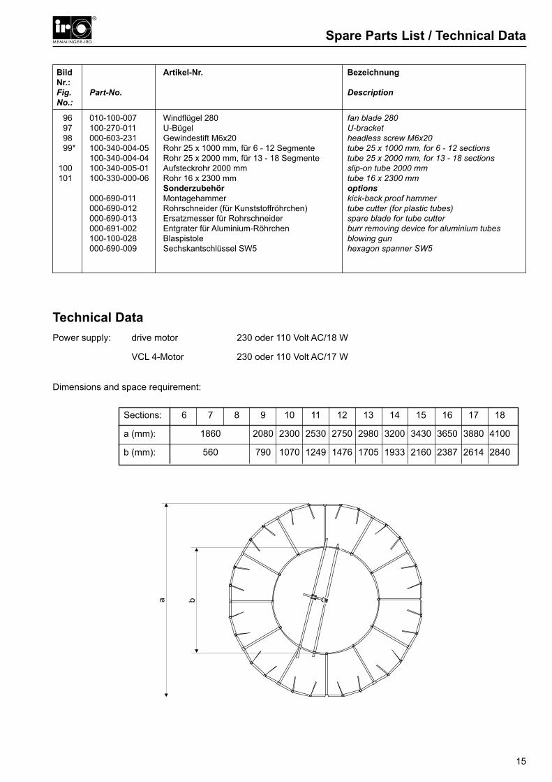
Dimensions and space requirement:
96 010-100-007 Windflügel 280 fan blade 280 97 100-270-011 U-Bügel U-bracket 98 000-603-231 Gewindestift M6x20 headless screw M6x20 99* 100-340-004-05 Rohr 25 x 1000 mm, für 6 - 12 Segmente tube 25 x 1000 mm, for 6 - 12 sections 100-340-004-04 Rohr 25 x 2000 mm, für 13 - 18 Segmente tube 25 x 2000 mm, for 13 - 18 sections 100 100-340-005-01 Aufsteckrohr 2000 mm slip-on tube 2000 mm 101 100-330-000-06 Rohr 16 x 2300 mm tube 16 x 2300 mm Sonderzubehör options 000-690-011 Montagehammer kick-back proof hammer 000-690-012 Rohrschneider (für Kunststoffröhrchen) tube cutter (for plastic tubes) 000-690-013 Ersatzmesser für Rohrschneider spare blade for tube cutter 000-691-002 Entgrater für Aluminium-Röhrchen burr removing device for aluminium tubes 100-100-028 Blaspistole blowing gun 000-690-009 Sechskantschlüssel SW5 hexagon spanner SW5
Sections: 6 7 8 9 10 11 12 13 14 15 16 17 18
a (mm): 1860 2080 2300 2530 2750 2980 3200 3430 3650 3880 4100
b (mm): 560 790 1070 1249 1476 1705 1933 2160 2387 2614 2840

16
Declaration of incorporation and conformity
Declaration of incorporationIn conformity with EU Machinery Directive 2006/42/EC, Annex II BIn conformity with the EU Low Voltage Directive 2006/95/EC
also
Declaration of conformityIn conformity with the EU Electro Magnetic Compatibility (EMC) Directive, 2004/108/EC
The manufacturer: Memminger-IRO Jakob-Mutz-Straße 7 72280 Dornstetten, Germany
hereby certifies that the following subassembly
Product name: FANCREEL
conforms to the requirements of the above named directives.
The subassembly is supplied complete with an original instruction manual and original technical documentation.
The subassembly may not be put into service until the machinery into which it is to be incorporated has been declared as being in conformity with the provisions of the EU Machinery Directive 2006/42/EC, Annex II A.
______________________________Dornstetten, 22.03.2010 M. Kleindorp, Company Management


MEMMINGER-IRO GmbH Tel.: +49 7443 281-0Postfach 1240 Fax: +49 7443 281-10172277 Dornstetten - Germany E-Mail: [email protected]ße 7 Internet: www.memminger-iro.de72280 Dornstetten - Germany
© 2005 MEMMINGER-IRO GmbH / 72277 Dornstetten - GermanyNachdruck, auch auszugsweise, nur mit schriftlicher Genehmigung der MEMMINGER-IRO GmbH.Änderungen vorbehalten.Reprint, even in extracts, shall require the written approval of MEMMINGER-IRO GmbH. Subject to modifications.