Embed Size (px)
Citation preview
Quality – Built In
ASSEMBLY INSTRUCTIONS
MK4A
BASE SIZE 4.210mm x 2545mm
Drill
Drill Bit 3.5mm
Drill Bit 6mm (for clear roof panel only)
Riveter
Hammer
Nail Punch
Tape Measure
Ladder or Saw stool
Spanners x 2
String Line
Tin Snips
Skillsaw and Jigsaw (for floor only)
Masonry Drill and 10mm Masonry Bit (for Bolt Down Kit only)
Read all instructions carefully.
Identify all parts and check quantities against checklist.
If you are making your own floor refer to Raised Base Plate section now.
Do not attempt to build your shed in high winds.
Beware of sharp edges.
Protect your eyes and ears.
Use electric tools with care. Use a Safety Trip Switch.
It is easier and quicker if this shed is erected by two people.
Your shed must be level. Achieve this by either levelling the ground or by using blocks.
If you shed is to be positioned on wet or damp ground, we recom-mend that your shed is raised up off the ground slightly.
Tools Required:
Select your site:
Safety:
Before you start:
ASSEMBLY INSTRUCTIONS
2

3
6
8
2
2
1
1
1
6
2.090m
1.890m
1.890m
2.330m
Gable End Wall Sheets - to suit 2049 wall
Wall Sheets
MK4 3/4 Wall Sheets - as per plan
Door - Standard Security
Instruction Booklet
Hardware Pack
Centre Door Stop
Touch-up Paint & Brush
Roof Sheets
0.580m
0.603 x 0.603m
0.588 x 0.150m
0.710 x 0.240m
1
Fixed Window Frame
Glaze Beads
Glass
Louvre Window Frame
Glass
Over Panel
Window Hardware Pack
2.830m
1.390m
1.390m
0.350m
0.900m
1
Roof Sheets
Flat Roof Sheet
Clear Roof Panel
Pressed Capping Sheet
Bevel Edge Support 45 x 45mm
Clear Roof Hardware Pack
Security Double Door Hardware Pack
Alarm - MA20
Shed light
Bolt Down Kit
Peg Down Kit
285 50mm Flooring Nails
18 75mm Flooring Nails
2 0.200 Jack Studs - 70 x 45
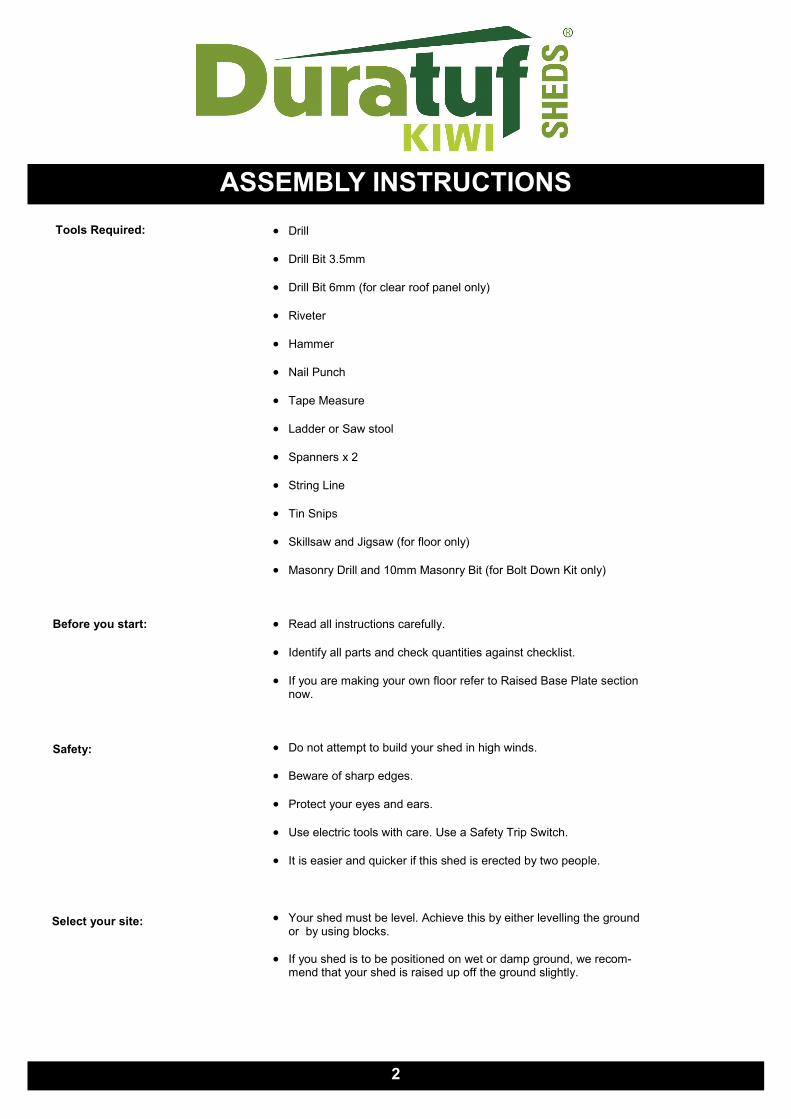
MK4A TIMBER FRAME
4
1900
(or 1870 for Raised Base Plate only)
YE
LL
OW
YE
LL
OW
YE
LL
OW
YE
LL
OW
YE
LL
OW
Y
EL
LO
W
YE
LL
OW
YE
LL
OW
YE
LL
OW
YE
LL
OW
1.8
10
45 45 45 45 1185 1185 1660
4210
45
45
45
FRONT WALL
45 45 45 45 1343 1343 1343
4210
45
45
45
BACK WALL
1900
(or 1870 for Raised Base Plate only)
88
3
88
3

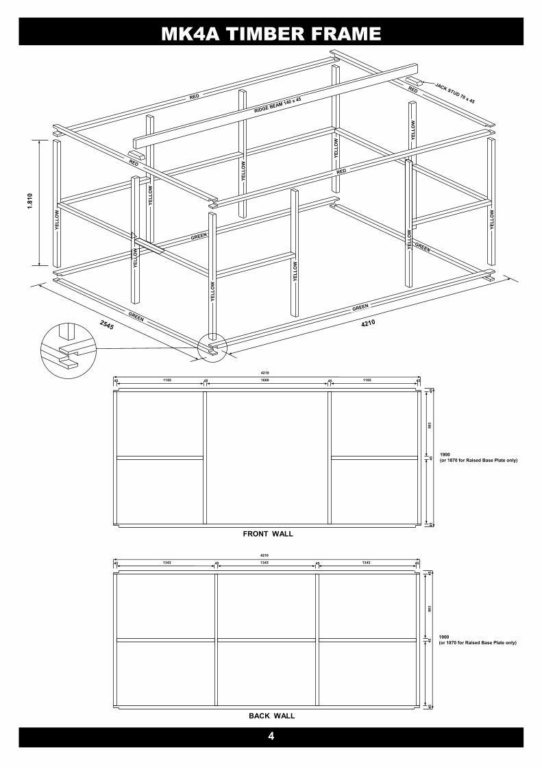
MK4A TIMBER FRAME
5
1
4
3
2
6
5
Step 3: Select two 2.545m Base Plates (Green) and two
2.545m Top Plates (Red). With front wall lying on the
ground, nail Plates to frame. Ensure Green joins to
Green and Red joins to Red.
Step 4: Position the back wall frame on top of plates. While
someone supports frame, nail in place. Nail in centre
Stud using 1.180m End Wall Nogs to get correct posi-
tion.
Step 6: Position a Jack Stud on each end of Ridge Beam and
nail in place using two 75mm nails each end (fig. 1).
Turnover Ridge Beam / Jack Studs, position centrally
on 2.545m Top Plates and nail to Top Plates using
two 75mm nails per Jack Stud.
fig. 1
Step 5: Carefully roll frame over onto its base. (Pieces of timber
from the packaging may be used to temporarily brace
the frame before rolling it over). Position 1.180m End
Wall Nogs .883m down from Top Plate and nail in
place. If fitting a Kiwi Floor, fit Floor Joists now. Space
joists equally and nail in place using three 75mm nails
per end.
Note: If fitting a window, there will be no centre stud on the window side. Instead nail in a full length nog (2.405 in
Gable or 4.120 in Back Wall) using window studs (.883) to get correct height. Position one window stud cen-
trally beneath the nog and nail in place. Further window studs and Nogs are fitted after the cladding is on.
Note: For sheds with the Raised Floor Modification option the studs will be 1.780m long to allow the Wall Sheets to pro-
trude 20mm below the Bottom Plate. Refer to Raised Floor Modification section (Page 15).
Step 1: Back Wall: Select one 4.210m Base Plate (Green),
one 4.210m Top Plate (Red) and four Studs (Yellow).
Lay out Plates and two Studs on a flat surface and nail
together using two 75mm nails per join. Nail in remain-
ing centre studs using 1.343m Nogs to get correct posi-
tion. Position Nogs .883m below Top Plate and nail in
place.
Step 2: Front Wall: Select one 4.210m Base Plate (Green),
one 4.210m Top Plate (Red), four Studs (Yellow) and
two 1.185m Nogs. Nail studs to each end of Plates.
Nail in remaining two studs using 1.185m Nogs to get
correct position. Position Nogs .883m below Top Plate
and nail in place.

MK4A WALL CLADDING
TO AVIOD CORROSION:
Where at all possible try not to trap metal filings between two sheets. Remove all metal filings before riveting.
Carbon in pencils reacts with the Zinc/Aluminium coating on steel. Use ink to mark steel.
TERMS EXPLANATION
To Tack: To Tack on a wall sheet means to use minimum nails hammered partly in to hold Wall Sheets in position. Should a Wall Sheet need to be re-positioned, the nails can easily be prized out.
If a window is required, identify Wall Sheet(s) with window hole pre-cut. Lean up Wall Sheets where window(s) are to be located.
Note:
When fitting Gable
End Sheets en-
sure they overlap
correctly (fig 1).
The overlap direc-
tion may differ
from cladding de-
tail.
6
CLADDING DETAIL
Birds Eye View
fig. 1

MK4A WALL CLADDING
Step 1: Front Wall: Start at the left hand side. Posi-
tion the Wall Sheet with the LIP on the left hand
side. Ensuring the LIP is flush with side of the
Stud and the top of the Top Plate, tack in place.
Repeat with Wall Sheet on the right hand side
of doorway. Ensure Rib without LIP is on the
right hand side of stud then tack in place. Posi-
tion 1/2 Wall Sheets as shown in the Cladding
Detail and tack in place.
Step 2: Back Wall: Position the first Wall Sheet with
the LIP on the right hand side. Ensuring the LIP
is flush with the side of the Studs and the top of
the Wall Sheet is flush with the top of the Top
Plate, tack in place. Position the next Wall
Sheet with the LIP on the right hand side. Over-
lap as shown in (fig 1). Ensuring Wall Sheet is
flush with top of Top Plate, tack in place. Re-
peat with remaining three sheets.
Step 4: Nailing Off: Nail one 30mm Clout each side of the Rib (two per Pan) into the Top Plates and Bottom
Plates. Nail Wall Sheets to mid wall Nogs (one per pan). Nail each corner Wall Sheet to Studs using two
30mm Clouts evenly spaced.
Gable Ends: When nailing Gable Wall Sheets to the Top Plate, use a String Line. At the top of the gable nail two
30mm Clouts into the end of the Ridge Beam. This will stop it from twisting.
Step 3: End Walls: Lean Gable Wall Sheets against
the shed to form gable shape. With the LIP
flush with side of Stud tack in place ensuring
the bottom of the Wall Sheet is 10mm above
the bottom of the Bottom Plate. Tack on re-
maining Wall Sheets. Repeat with other gable
end. If fitting a window, nail in Window Studs
and Nog now. Refer to Window instructions.
7
EDGE
FLUSH
TOP
FLUSH
8
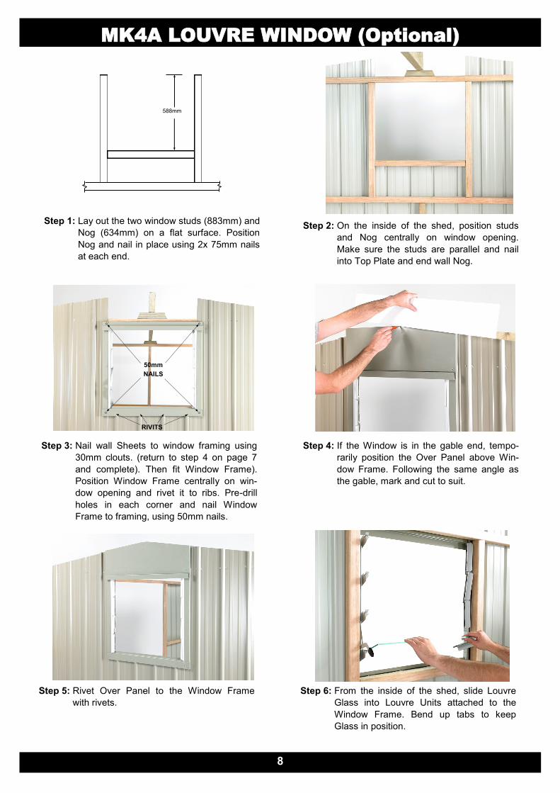
MK4A LOUVRE WINDOW (Optional)
Step 2: On the inside of the shed, position studs
and Nog centrally on window opening.
Make sure the studs are parallel and nail
into Top Plate and end wall Nog.
Step 3: Nail wall Sheets to window framing using
30mm clouts. (return to step 4 on page 7
and complete). Then fit Window Frame).
Position Window Frame centrally on win-
dow opening and rivet it to ribs. Pre-drill
holes in each corner and nail Window
Frame to framing, using 50mm nails.
Step 4: If the Window is in the gable end, tempo-
rarily position the Over Panel above Win-
dow Frame. Following the same angle as
the gable, mark and cut to suit.
Step 5: Rivet Over Panel to the Window Frame
with rivets.
588mm
Step 1: Lay out the two window studs (883mm) and
Nog (634mm) on a flat surface. Position
Nog and nail in place using 2x 75mm nails
at each end.
Step 6: From the inside of the shed, slide Louvre
Glass into Louvre Units attached to the
Window Frame. Bend up tabs to keep
Glass in position.
50mm
NAILS
RIVITS
9
Step1: Fit Door Jamb Flashing (A104) in be-
tween Top and Bottom Plates and hard
against Stud. Attach Door Jamb Flash-
ing with three 30mm clouts into studs on
the inside and three 50 mm nails on the
outside. Pre-drill holes on the outside to
protect flashing. Repeat with the other
Door Jamb.
Step2: Measure and cut Doorstep Flashing (A106)
to fit in between Door Jambs. Positioning
the Doorstep Flashing in between Door
Jambs at bottom of doorway, nail through
top of flashing using five 30mm Clouts. Re-
peat with the Overdoor Flashing (A105).
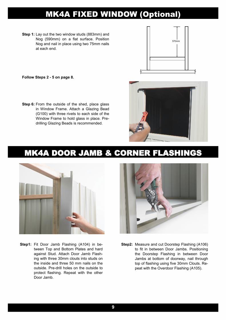
Step 1: Lay out the two window studs (883mm) and
Nog (590mm) on a flat surface. Position
Nog and nail in place using two 75mm nails
at each end.
570mm
Step 6: From the outside of the shed, place glass
in Window Frame. Attach a Glazing Bead
(G100) with three rivets to each side of the
Window Frame to hold glass in place. Pre-
drilling Glazing Beads is recommended.
MK4A FIXED WINDOW (Optional)
Follow Steps 2 - 5 on page 8.
MK4A DOOR JAMB & CORNER FLASHINGS
MK4A DOOR JAMB & CORNER FLASHINGS
10
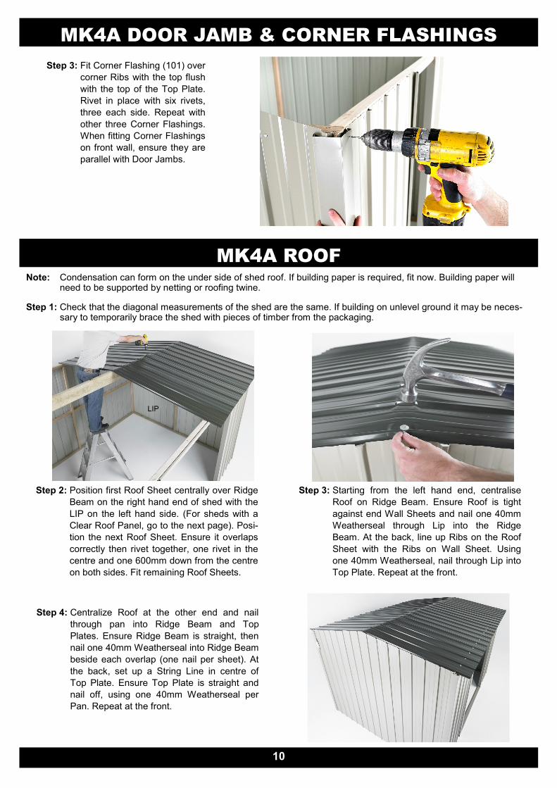
Step 3: Fit Corner Flashing (101) over
corner Ribs with the top flush
with the top of the Top Plate.
Rivet in place with six rivets,
three each side. Repeat with
other three Corner Flashings.
When fitting Corner Flashings
on front wall, ensure they are
parallel with Door Jambs.
MK4A ROOF
Note: Condensation can form on the under side of shed roof. If building paper is required, fit now. Building paper will need to be supported by netting or roofing twine.
Step 1: Check that the diagonal measurements of the shed are the same. If building on unlevel ground it may be neces-sary to temporarily brace the shed with pieces of timber from the packaging.
Step 2: Position first Roof Sheet centrally over Ridge
Beam on the right hand end of shed with the
LIP on the left hand side. (For sheds with a
Clear Roof Panel, go to the next page). Posi-
tion the next Roof Sheet. Ensure it overlaps
correctly then rivet together, one rivet in the
centre and one 600mm down from the centre
on both sides. Fit remaining Roof Sheets.
Step 4: Centralize Roof at the other end and nail
through pan into Ridge Beam and Top
Plates. Ensure Ridge Beam is straight, then
nail one 40mm Weatherseal into Ridge Beam
beside each overlap (one nail per sheet). At
the back, set up a String Line in centre of
Top Plate. Ensure Top Plate is straight and
nail off, using one 40mm Weatherseal per
Pan. Repeat at the front.
LIP
Step 3: Starting from the left hand end, centralise
Roof on Ridge Beam. Ensure Roof is tight
against end Wall Sheets and nail one 40mm
Weatherseal through Lip into the Ridge
Beam. At the back, line up Ribs on the Roof
Sheet with the Ribs on Wall Sheet. Using
one 40mm Weatherseal, nail through Lip into
Top Plate. Repeat at the front.
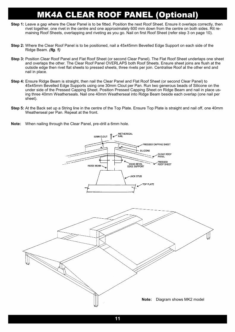
MK4A CLEAR ROOF PANEL (Optional)
Step 1: Leave a gap where the Clear Panel is to be fitted. Position the next Roof Sheet. Ensure it overlaps correctly, then rivet together, one rivet in the centre and one approximately 600 mm down from the centre on both sides. Rit re-maining Roof Sheets, overlapping and riveting as you go. Nail on first Roof Sheet (refer step 3 on page 10).
Step 2: Where the Clear Roof Panel is to be positioned, nail a 45x45mm Bevelled Edge Support on each side of the Ridge Beam. (fig. 1)
Step 3: Position Clear Roof Panel and Flat Roof Sheet (or second Clear Panel). The Flat Roof Sheet underlaps one sheet and overlaps the other. The Clear Roof Panel OVERLAPS both Roof Sheets. Ensure sheet joins are flush at the outside edge then rivet flat sheets to pressed sheets, three rivets per join. Centralise Roof at the other end and nail in place.
Step 4: Ensure Ridge Beam is straight, then nail the Clear Panel and Flat Roof Sheet (or second Clear Panel) to 45x45mm Bevelled Edge Supports using one 30mm Clout per Pan. Run two generous beads of Silicone on the under side of the Pressed Capping Sheet. Position Pressed Capping Sheet on Ridge Beam and nail in place us-ing three 40mm Weatherseals. Nail one 40mm Weatherseal into Ridge Beam beside each overlap (one nail per sheet).
Step 5: At the Back set up a String line in the centre of the Top Plate. Ensure Top Plate is straight and nail off, one 40mm Weatherseal per Pan. Repeat at the front.
Note: When nailing through the Clear Panel, pre-drill a 6mm hole.
11
Note: Diagram shows MK2 model
12
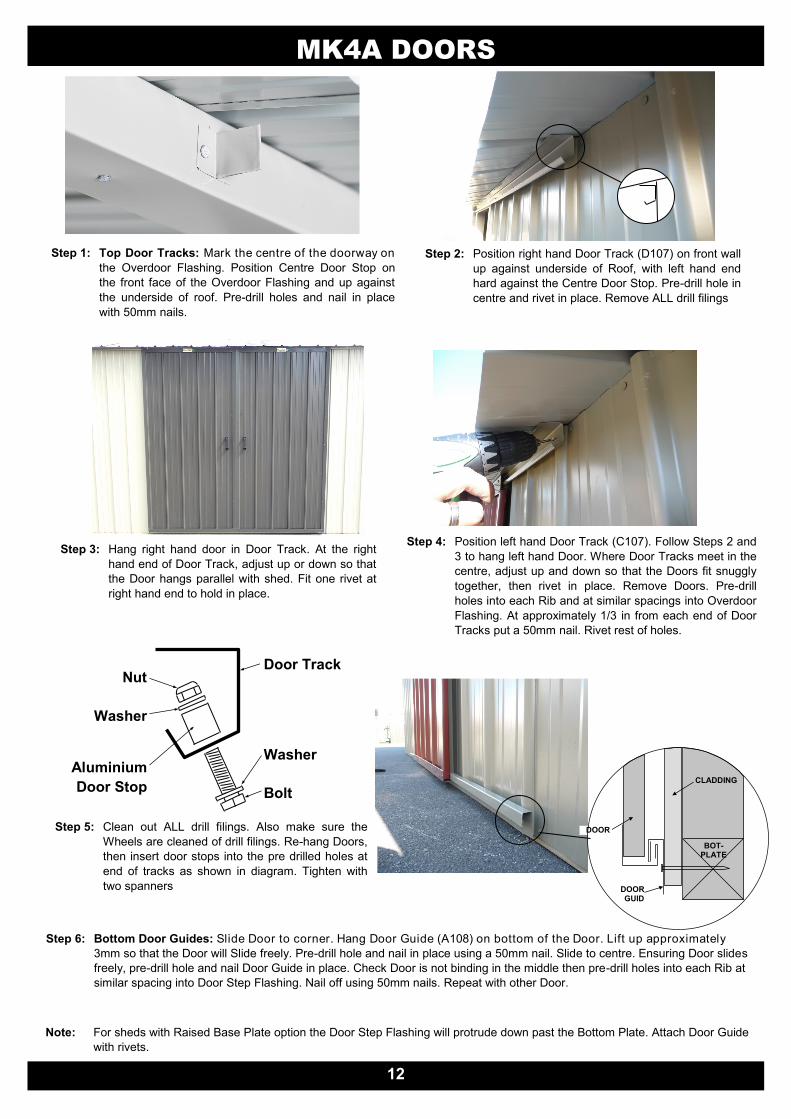
MK4A DOORS
Step 2: Position right hand Door Track (D107) on front wall
up against underside of Roof, with left hand end
hard against the Centre Door Stop. Pre-drill hole in
centre and rivet in place. Remove ALL drill filings
Step 3: Hang right hand door in Door Track. At the right
hand end of Door Track, adjust up or down so that
the Door hangs parallel with shed. Fit one rivet at
right hand end to hold in place.
Step 4: Position left hand Door Track (C107). Follow Steps 2 and
3 to hang left hand Door. Where Door Tracks meet in the
centre, adjust up and down so that the Doors fit snuggly
together, then rivet in place. Remove Doors. Pre-drill
holes into each Rib and at similar spacings into Overdoor
Flashing. At approximately 1/3 in from each end of Door
Tracks put a 50mm nail. Rivet rest of holes.
Step 1: Top Door Tracks: Mark the centre of the doorway on
the Overdoor Flashing. Position Centre Door Stop on
the front face of the Overdoor Flashing and up against
the underside of roof. Pre-drill holes and nail in place
with 50mm nails.
Step 5: Clean out ALL drill filings. Also make sure the
Wheels are cleaned of drill filings. Re-hang Doors,
then insert door stops into the pre drilled holes at
end of tracks as shown in diagram. Tighten with
two spanners
Door Track
Bolt
Washer
Washer
Nut
Aluminium
Door Stop
DOOR
GUIDDOOR
CLADDING
BOT-PLATE
Step 6: Bottom Door Guides: Slide Door to corner. Hang Door Guide (A108) on bottom of the Door. Lift up approximately
3mm so that the Door will Slide freely. Pre-drill hole and nail in place using a 50mm nail. Slide to centre. Ensuring Door slides
freely, pre-drill hole and nail Door Guide in place. Check Door is not binding in the middle then pre-drill holes into each Rib at
similar spacing into Door Step Flashing. Nail off using 50mm nails. Repeat with other Door.
Note: For sheds with Raised Base Plate option the Door Step Flashing will protrude down past the Bottom Plate. Attach Door Guide
with rivets.
13
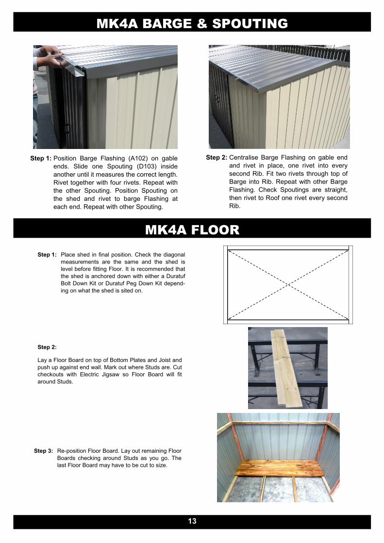
MK4A BARGE & SPOUTING
Step 1: Position Barge Flashing (A102) on gable
ends. Slide one Spouting (D103) inside
another until it measures the correct length.
Rivet together with four rivets. Repeat with
the other Spouting. Position Spouting on
the shed and rivet to barge Flashing at
each end. Repeat with other Spouting.
Step 2: Centralise Barge Flashing on gable end
and rivet in place, one rivet into every
second Rib. Fit two rivets through top of
Barge into Rib. Repeat with other Barge
Flashing. Check Spoutings are straight,
then rivet to Roof one rivet every second
Rib.
MK4A FLOOR
Step 1: Place shed in final position. Check the diagonal
measurements are the same and the shed is
level before fitting Floor. It is recommended that
the shed is anchored down with either a Duratuf
Bolt Down Kit or Duratuf Peg Down Kit depend-
ing on what the shed is sited on.
Step 2:
Lay a Floor Board on top of Bottom Plates and Joist and
push up against end wall. Mark out where Studs are. Cut
checkouts with Electric Jigsaw so Floor Board will fit
around Studs.
Step 3: Re-position Floor Board. Lay out remaining Floor
Boards checking around Studs as you go. The
last Floor Board may have to be cut to size.
MK4A FLOOR
14
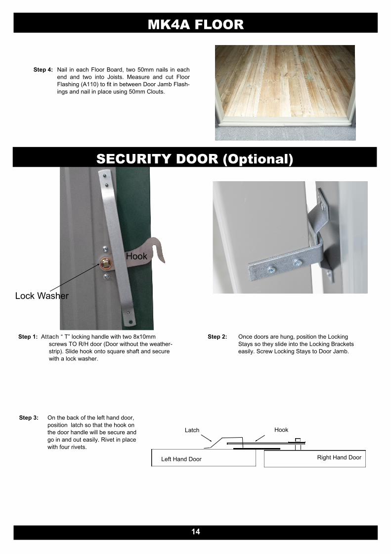
Step 4: Nail in each Floor Board, two 50mm nails in each
end and two into Joists. Measure and cut Floor
Flashing (A110) to fit in between Door Jamb Flash-
ings and nail in place using 50mm Clouts.
Step 1: Attach “ T” locking handle with two 8x10mm
screws TO R/H door (Door without the weather-
strip). Slide hook onto square shaft and secure
with a lock washer.
Hook
Lock Washer
Step 2: Once doors are hung, position the Locking
Stays so they slide into the Locking Brackets
easily. Screw Locking Stays to Door Jamb.
SECURITY DOOR (Optional)
Step 3: On the back of the left hand door,
position latch so that the hook on
the door handle will be secure and
go in and out easily. Rivet in place
with four rivets.
Left Hand Door Right Hand Door
Hook Latch
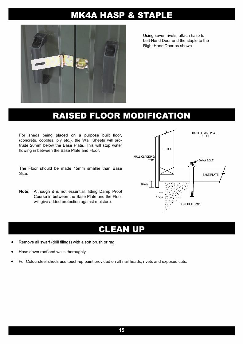
MK4A HASP & STAPLE
Using seven rivets, attach hasp to
Left Hand Door and the staple to the
Right Hand Door as shown.
RAISED FLOOR MODIFICATION
For sheds being placed on a purpose built floor,
(concrete, cobbles, ply etc.), the Wall Sheets will pro-
trude 20mm below the Base Plate. This will stop water
flowing in between the Base Plate and Floor.
The Floor should be made 15mm smaller than Base
Size.
Note: Although it is not essential, fitting Damp Proof
Course in between the Base Plate and the Floor
will give added protection against moisture.
CLEAN UP
Remove all swarf (drill filings) with a soft brush or rag.
Hose down roof and walls thoroughly.
For Coloursteel sheds use touch-up paint provided on all nail heads, rivets and exposed cuts.
15
DURATUF PREMIUM SHED WARRANTY
GUARANTEE TO CUSTOMER Congratulations on purchasing a Duratuf Storage Shed. With proper care and attention, this product will last many years. For your benefit PLEASE READ THE FOLLOWING INFORMATION CAREFULLY.
WARRANTY ON METAL CLADDING Riverlea Group Ltd guarantee that the metal roofing and wall cladding on Kiwi and Fortress Garden Sheds may be used in moderate and inland corrosion zones or areas where the first year mild steel corrosion rate is less than 200g/m2, and that in these conditions, they will not perforate due to corrosion within 18 years of date of manufacture.
TERMS AND CONDITIONS 1. Damage or corrosion due to the following circumstances is not covered by this warranty.
Mechanical, chemical or other damage sustained during or after installation. NOTE: Clean swarf off shed IMMEDIATELY after assembly Do NOT mark cladding with pencil Do NOT allow manures, chemicals or other corrosive materials to have direct contact with cladding Chemical damage will result if these instructions are not carried out
Force majeure or other causes beyond the control of Riverlea Group Ltd.
2. This warranty does not cover material installed in severe and very severe environmental situations, or in any area where the mild steel corrosion rate (as published by BRANZ) exceeds 200g/m2.
3. Minimum maintenance must be carried out in accordance with instructions below. Should the cladding fail to perform as specified above, the liability of Riverlea Group Ltd shall in all cases be limited to replacing or repairing the defective product. The balance of the original warranty will cover any repaired or replaced material. Riverlea Group Ltd will not be liable for any consequential loss or damage, labour or transport charges. All claims made in writing within 21 days of discovery, quoting the reference number at the top right hand corner of this page.
MAINTENANCE Following are the minimum maintenance requirements for cladding used in Kiwi Garden Sheds and Fortress Sheds.
Washing all surfaces by rain, and annual hosing of sheltered areas using a hose and soft nylon brush.
Within 2km of coast—wash every 3 months as above. After a storm, wash the cladding and the gutters as soon as possible to remove any highly corrosive salt deposits.
Volcanic Ash Fallout—wash as soon as possible, removing fallout from roof and gutters
Gutters to be kept clean of leaves and dirt. Should you require additional technical information please contact us at the details below.
Please visit http://www.riverleagroup.co.nz/warranty-garden-sheds to validate the Warranty on your shed.
Click on the Warranty Registration Link and complete all details.
If you are unable to access the computer, please phone us on 0800 438 274 and one of the customer services team will help you to acti-
vate the warranty on your garden shed.
Many thanks, from the Team at Riverlea Group.
WARRANTY REGISTRATION