Embed Size (px)
Citation preview
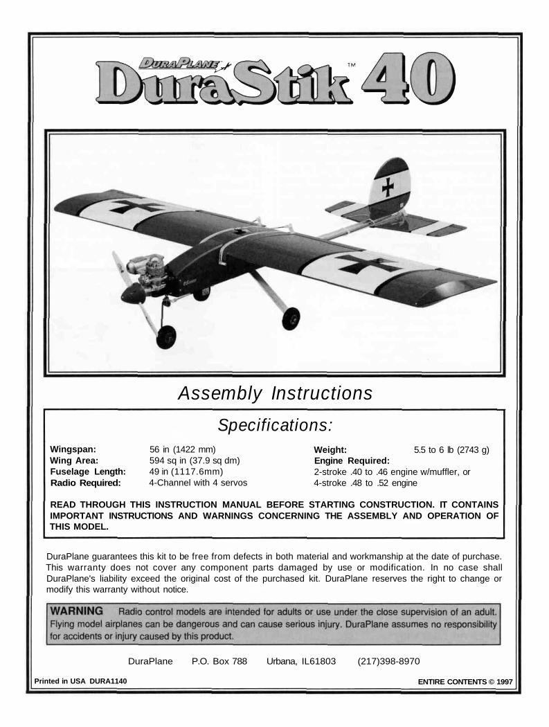
Assembly InstructionsSpecifications:
Wingspan:Wing Area:Fuselage Length:Radio Required:
56 in (1422 mm)594 sq in (37.9 sq dm)49 in (1117.6mm)4-Channel with 4 servos
Weight: 5.5 to 6 lb (2743 g)Engine Required:2-stroke .40 to .46 engine w/muffler, or4-stroke .48 to .52 engine
READ THROUGH THIS INSTRUCTION MANUAL BEFORE STARTING CONSTRUCTION. IT CONTAINSIMPORTANT INSTRUCTIONS AND WARNINGS CONCERNING THE ASSEMBLY AND OPERATION OFTHIS MODEL.
DuraPlane guarantees this kit to be free from defects in both material and workmanship at the date of purchase.This warranty does not cover any component parts damaged by use or modification. In no case shallDuraPlane's liability exceed the original cost of the purchased kit. DuraPlane reserves the right to change ormodify this warranty without notice.
DuraPlane P.O. Box 788 Urbana, IL61803 (217)398-8970
Printed in USA DURA1140 ENTIRE CONTENTS © 1997

Thank you for purchasing the DuraPlane DuraStik 40 TheDuraStik 40 is the third generation of DuraPlane modelsspecifically designed for aerobatic flight The stickconfiguration is reminiscent of the popular Great Planes stik""series and is a perfect subject for a fast building aerobatic,fun flying DuraPlane model Because the DuraStik 40 is fullyaerobatic featuring a wing that has no dihedral (and does notpossess the self-righting characteristics found in a trainer), itis recommended that you do not attempt to fly the DuraStik40 as your first model.
If this is your first model, the best way to learn to fly R/C isto join a flying club The Academy of Model Aeronautics isthe national organization that charters model clubs,sanctions competitions, and insures flying fields across theUnited States We urge you to join the AMA Membershipwill bring you flying insurance, a subscription to ModelAviation Magazine, and many other benefits The AMA willgladly send you membership information and lists of AMAchartered clubs in your area where you can seek the helpof experienced modelers.
Academy of Model Aeronautics5151 East Memorial Drive
Muncie, Indiana 47302-9252(800) 435-9262
FAX (765) 741-0057Web Site: HTTP .//WWW.MODELAIRCRAFT.ORG
Your hobby shop is also an invaluable place for service,parts and information that you require We urge you topatronize your local hobby dealer - he s there to help youenjoy your hobby.
#11 Blades (HCAR0311, 100 qty.)Razor Plane (MASR1510)Standard and Phillips screwdriversNeedle nose pliersElectric drillDrill Bits 1/16", 3/32", 7/64", 1/8", 5/32",#19 (or 11/64"), 3/16", 15/64" (or 1/4")X-Acto Building Square (XACR7726)Kyosho Lexan Curved Scissors (KYOR1010)Masking TapeWaxed paperTopFlite Sealing Iron (TOPR2100)Top Flite "Hot Sock" (TOPR2175)Easy-Touch "Bar Sanders"Great Planes C G Machine (GPMR2400)
*A flat, durable, easy to handle sanding tool is a necessityfor building a well finished model Great Planes makes acomplete range of Easy-Touch Bar Sanders (patentpending) and replaceable Easy-Touch Adhesive-BackedSandpaper While building the DuraStik, we used a 5-1/2"Bar Sander and an 11" Bar Sander equipped with 80-gritand 150-grit Adhesive-backed Sandpaper.
This instruction manual provides step-by-step instructions forassembling the DuraStik 40 kit Assembly of the DuraStik 40consists of six major steps, completed in the following order
BUILD THE TAIL FEATHERS..................................4
ASSEMBLE THE FUSELAGE...................................6
RADIO INSTALLATION ............................................9
BUILD THE WING ...................................................12
COVER THE WING AND TAIL................................15
FINAL ASSEMBLY..................................................17
FLIGHT....................................................................19
Here's the complete list of Easy-Touch Bar Sanders andAdhesive Backed Sandpaper.
5-1/2" Bar Sander (GPMR6169)11" Bar Sander (GPMR6170)22" Bar Sander (GPMR6172)33" Bar Sander (GPMR6174)44" Bar Sander (GPMR6176)
Adhesive-backed 12' roll of:80-grit (GPMR6180)
150-grit (GPMR6183)180-grit (GPMR6184)220-grit (GPMR6185)
Assortment pack of 5-1/2" strips (GPMR6189)
We use 3M 320-grit wet-or-dry sandpaper for finish sanding.
2
Four channel radio w/4 servos40 to 46 2-stroke engine w/muffler, or 48 to 524-stroke enginePropellers recommended by your engine manufacturer1 Roll EconoKote or Black Baron film low-heatmodel covering (see Covering, page 16)Fuel-proof spray paint (see Painting, page 16)(3) 2 1/2" wheels (GPMQ4223)2-1/4" Spinner (GPMQ4517 - red)8 oz Fuel tank (GPMQ4103)Medium silicone fuel tubing (GPMQ4131)#64 Rubber bands (HCAQ2030)1/4" R/C foam rubber sheet (HCAQ1000)3/4" Wide fiber reinforced strapping tape1/16" Wing seating foam tape (GPMQ4422)
These are additional items you will need to complete yourDuraStik that are not included with your kit. Suggestedorder numbers are in parentheses
When a specific type of adhesive works best for that step,we will tell you what type of glue to use CA dissolvesfoam so do not use it on any part of the wing where itwill contact the foam. Whenever just epoxy is specifiedyou may use either 30-minute epoxy or 6-minute epoxyWhen 30-minute epoxy is specified it is recommendedthat you use only 30-minute epoxy because you will needthe working time and/or the additional strength
When you get to each step, read that step completelythrough to the end before you begin Frequently there isimportant information or a note at the end of the step that youneed to know before you start Photos and sketches areplaced ahead of the step they refer to You can study photosin the following steps to get another view of the same parts.
Refer to the Parts List for a description of the parts andhardware included with the DuraStik 40 kit
Here's a checklist of supplies you should have on handwhile you're building We always use Great Planes Pro"CA and Epoxy.
1 oz Medium CA+ (GPMR6008)1 oz Thin CA (GPMR6002)CA Accelerator (GPMR6035)CA Applicator Tips (HCAR3780)30-minute (GPMR6047) or 6-minute epoxy(GPMR6045)Pro Wood Glue (GPMR6161)Pro Threadlocker (GPMR6060)Lightweight Hobby Filler (White, HCAR3400)Denatured or IsopropyI Alcohol (to clean up excessepoxy)
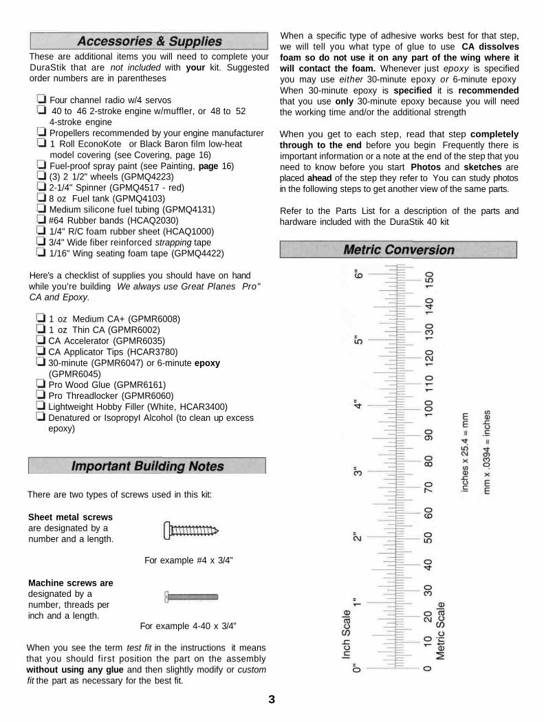
There are two types of screws used in this kit:
Sheet metal screwsare designated by anumber and a length.
For example #4 x 3/4"
Machine screws aredesignated by anumber, threads perinch and a length.
For example 4-40 x 3/4"
When you see the term test fit in the instructions it meansthat you should first position the part on the assemblywithout using any glue and then slightly modify or customfit the part as necessary for the best fit.
3
blade to cut the hinge slots in the center of the fin TE andthe center of the rudder LE at the locations you marked.
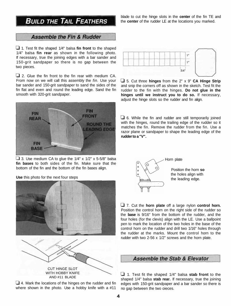
1. Test fit the shaped 1/4" balsa fin front to the shaped1/4" balsa fin rear as shown in the following photo.If necessary, true the joining edges with a bar sander and150-grit sandpaper so there is no gap between thetwo pieces.
2. Glue the fin front to the fin rear with medium CA.From now on we will call this assembly the fin. Use yourbar sander and 150-grit sandpaper to sand the sides of thefin flat and even and round the leading edge. Sand the finsmooth with 320-grit sandpaper.
5. Cut three hinges from the 2" x 9" CA Hinge Stripand snip the corners off as shown in the sketch. Test fit therudder to the fin with the hinges. Do not glue in thehinges until we instruct you to do so. If necessary,adjust the hinge slots so the rudder and fin align.
6. While the fin and rudder are still temporarily joinedwith the hinges, round the trailing edge of the rudder so itmatches the fin. Remove the rudder from the fin. Use arazor plane or sandpaper to shape the leading edge of therudder to a "V".
fin bases to both sides of the fin. Make sure that thebottom of the fin and the bottom of the fin bases align.
Use this photo for the next four steps
where shown in the photo. Use a hobby knife with a #11
3. Use medium CA to glue the 1/4" x 1/2" x 5-5/8" balsa
CUT HINGE SLOTWITH HOBBY KNIFE
AND #11 BLADE
4. Mark the locations of the hinges on the rudder and fin
Horn plate
Position the horn sothe holes align withthe leading edge.
7. Cut the horn plate off a large nylon control horn.Position the control horn on the right side of the rudder sothe base is 9/16" from the bottom of the rudder, and thefour holes (for the clevis) align with the LE. Use a ballpointpen to mark the location of the two holes in the base of thecontrol horn on the rudder and drill two 1/16" holes throughthe rudder at the marks. Mount the control horn to therudder with two 2-56 x 1/2" screws and the horn plate.
1. Test fit the shaped 1/4" balsa stab front to theshaped 1/4" balsa stab rear. If necessary, true the joiningedges with 150-grit sandpaper and a bar sander so there isno gap between the two oieces.
4

2. Glue the stab front to the stab rear with medium CA.From now on we will call this assembly the stab. Use150-grit sandpaper and a sanding block to round theleading edge of the stab and sand the top and bottom flatand even. Sand the stab smooth with 320-grit sandpaper.
7. Mount a control horn to the top of the elevator with two2-56 x 1/2" screws and the horn plate. Position the edge ofthe horn base 8-7/16" from the left edge of the elevator.
3. Draw a vertical centerline on the center of the stab andthe 1/16" x 1-1/8" x 6" plywood stabilizer bottom plate.
4. Use medium CA to glue the stab bottom plate to thestab with the centerlines aligned. After the CA hardens,shape the front of the stab bottom plate so it matches thefront of the stab.
a 1. Inspect the holes in the aluminum fuselage channeland remove any burrs you find with a metal file.
5. Mark the locations of the hinges on the stab and 1/4"shaped balsa elevator as shown in the photo at step 7.Cut the hinge slots in the stab and elevator the same wayyou did the fin and rudder. Cut four more hinges from theCA hinge strip and test fit the elevator to the stab with thehinges. If necessary, adjust hinge slots that don't align.
6. While the elevator and stab are still temporarily joinedwith the hinges, round the ends and TE of the elevator tomatch the stab. Remove the elevator and use a razorplane or sandpaper to shape the leading edge of theelevator to a "V".
2. Insert the fin in the aluminum fuselage channel so thetrailing edge aligns with the aft edge of the channel. Markthe location of the holes in the bottom and sides of thefuselage channel onto the fin. Remove the fin and drill 1/8"holes through only the marks on the side of the fin.
5
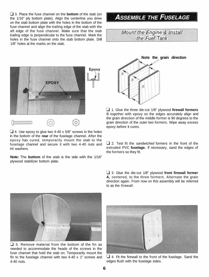
the 1/16" ply bottom plate). Align the centerline you drewon the stab bottom plate with the holes in the bottom of thefuse channel and align the trailing edge of the stab with theaft edge of the fuse channel. Make sure that the stabtrailing edge is perpendicular to the fuse channel. Mark theholes in the fuse channel onto the stab bottom plate. Drill1/8" holes at the marks on the stab.
Mount the Engine & Installthe Fuel Tank
3. Place the fuse channel on the bottom of the stab (on
Note the grain direction
1. Glue the three die-cut 1/8" plywood firewall formersB together with epoxy so the edges accurately align andthe grain direction of the middle former is 90 degrees to thegrain direction of the outer two formers. Wipe away excessepoxy before it cures.
4. Use epoxy to glue two 4-40 x 5/8" screws in the holesin the bottom of the rear of the fuselage channel. After theepoxy has cured, temporari ly mount the stab to thefuselage channel and secure it with two 4-40 nuts and#4 washers.
Note: The bottom of the stab is the side with the 1/16"plywood stabilizer bottom plate.
2. Test fit the sandwiched formers in the front of theextruded PVC fuselage. If necessary, sand the edges ofthe formers so they fit.
3. Glue the die-cut 1/8" plywood front firewall formerA, centered, to the three formers. Alternate the graindirection again. From now on this assembly will be referredto as the firewall.
5. Remove material from the bottom of the fin asneeded to accommodate the heads of the screws in thefuse channel that hold the stab on. Temporarily mount thefin to the fuselage channel with two 4-40 x 1" screws and4-40 nuts.
4. Fit the firewall to the front of the fuselage. Sand theedges flush with the fuselage sides.
6

5. Cut the spreader bar and other flashing from the rightand left Great Planes 40-70 engine mount halves.
6. Drill four 5/32" holes through the firewall at the fourpunch marks in firewall former A. Use a hammer to lightlytap four 6-32 blind nuts into the holes in the back of thefirewall. Permanently secure the blind nuts to the firewallwith thin CA.
7. Fasten the engine mount to the firewall with four6-32 x 1-1/2" bolts and #6 lock washers and flat washers.Do not fully tighten the bolts so you can adjust the enginemount to fit your engine.
For a sportier appearance, you may side mount yourengine. Just rotate your engine mount (or the firewall) 90degrees and drill the holes for the fuel lines and throttlepushrod accordingly. This also locates the muffler belowthe fuselage which greatly reduces exhaust residuedeposited on your model!
secure. Position your engine on the mount and mark thelocation of the mounting holes.
Hint: Sharpen the end of a 1/16" wire rod to a point. Heatthe rod with a lighter and use it to mark the mounting holeson the engine mount.
9. Drill four 3/32" holes at the marks you made formounting your engine with #4 x 3/4" sheet metal screw and#4 washers included with this kit. If you prefer to mountyour engine with 4-40 screws, drill the holes with a #43 (or3/32") drill. Tap the holes with a 4-40 tap. Use 4-40 x 3/4"screws (not included).
Note: #4 or 4-40 screws are intended for sport enginessuch as the O.S. LA or FP' series. If you are using a morepowerful engine, use #6 or 6-32 screws to mount yourengine. Drill the holes with a 7/64" drill for #6 screws or a#36 or 7/64" drill for 6-32 screws.
10. Take the engine mount off the firewall. Drill a 3/16"hole through the firewall that aligns with the carburetorarm. Make sure you don't drill the hole where the enginemount will be. If the engine mount will be in the way, drillthe hole close to the engine mount to give the throttlepushrod the straightest run possible to the carburetor arm.Drill 15/64" (or 1/4") holes through the firewall for the fuellines. Make sure the holes will not interfere with the enginemount. When you're done, your firewall should looksomething like the one in the photo.
8. Slide the engine mount halves in or out to fit yourengine. Tighten the 6-32 bolts so the engine mount is
11. Mark the locations on the sides, top, and bottom ofthe front of the fuselage for the firewall mounting holes,evenly spaced, 1/4" behind the front edge. Fit the firewall
7
into the fuselage, making sure the hole for the throttlepushrod is in the correct orientation Tightly tape the firewallin place with masking tape Confirm that the locations of theholes will not interfere with the throttle pushrod If they do,adjust the locations of those holes Drill holes through thefuselage and into the firewall with a 3/32" drill.
12 Remove the firewall Assemble your fuel tankConnect about 8" of fuel line onto the pickup and pressurefittings on your fuel tank Place an approximately 4" x 4"piece of 1/4" thick R/C foam rubber in the fuselage asshown in the photo so the front edge is about 3/4" aft of thefront edge of the fuse Insert the fuel tank into the fuse withthe R/C foam rubber Slide the 12" long, 3/16" grey outerpushrod guide tube into the fuse between the R/C foamand the fuse so the end will fit in the hole you drilled inthe firewall
13 Fit the firewall to the fuselage, simultaneously
2 Enlarge the middle hole in the pre bent aluminumlanding gear with a 3/16"dnll Place the landing gear onthe bottom of the fuse and insert an 8 32 x 1/2" sockethead cap screw (from now on referred to as cap screw)into the middle hole of the landing gear and into the fuseDrill a 7/64" hole through the fuselage where the outerholes in the landing gear align with the line on the bottomof the fuselage The shaded areas show the location of thelanding gear plates that will be installed in step 3.
3 Round one corner on the bottom of both landing gearplates so they fit the curve inside the fuselage The bottomof the landing gear plates is the side with the line you drew.Place one of the landing gear plates inside the fuselage sothe line you marked is visible through one of the holes youdrilled in the bottom of the fuse Mark the location of the holeon the landing gear plate Drill a 7/64" hole through the plateat the mark you made Mark and drill the other landing gearplate in the other side of the fuse the same way
routing the fuel lines and the throttle guide tube through theholes you drilled Temporarily fasten the firewall to the fusewith eight #4 x 3/8" screws
4 Enlarge the outer two landing gear holes in thefuselage only with a 5/32" drill bit Use two #6 x 1/2"screws to mount the landing gear to the fuselage with thelanding gear plates inside You may glue the landing gearplates to the fuselage with epoxy, but this is not necessary.
Mount the Landing Gear
5/32" Wheel Collar
Nylon Steering armwith 5/32" WheelCollar and 6-32 x1/4" Screw
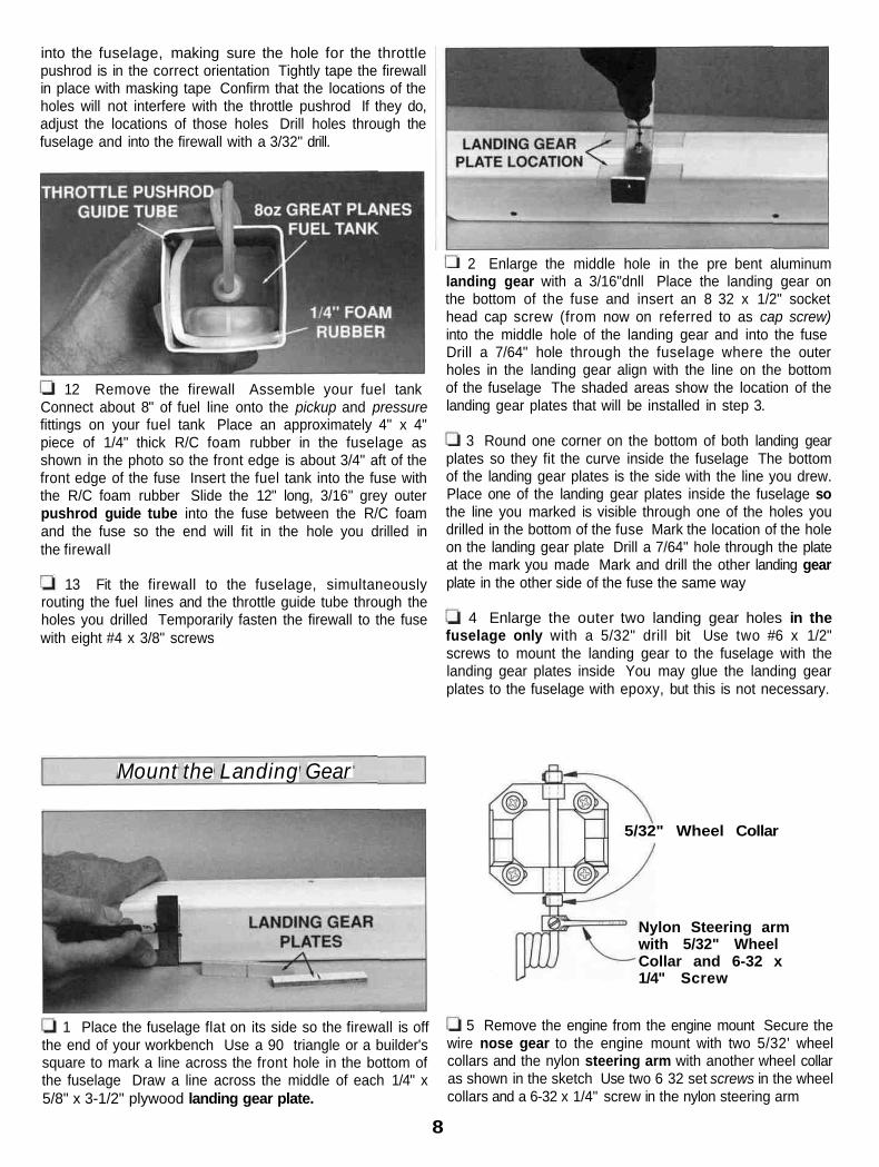
1 Place the fuselage flat on its side so the firewall is off 5 Remove the engine from the engine mount Secure thethe end of your workbench Use a 90 triangle or a builder'ssquare to mark a line across the front hole in the bottom ofthe fuselage Draw a line across the middle of each 1/4" x5/8" x 3-1/2" plywood landing gear plate.
wire nose gear to the engine mount with two 5/32' wheelcollars and the nylon steering arm with another wheel collaras shown in the sketch Use two 6 32 set screws in the wheelcollars and a 6-32 x 1/4" screw in the nylon steering arm
8

6. Drill the hub of two 2-1/2" main wheels with a #19 (or11/64") drill. Secure each wheel to the landing gear with an8-32 x 1-1/4" cap screw and two 8-32 nuts as shown in thephoto. Use thread locking compound on the nuts. Mountthe front wheel to the nose gear with two 5/32" wheelcollars. For a finished appearance, cut the excess wire offthe landing gear that protrudes beyond the wheel collar(you should do this on all your models').
7. Place the fuselage on your workbench. Adjust thewheel collars on the nose gear so the fuselage is level.Secure the 6-32 screws in the wheel collars with a drop ofthread lock or CA.
Optional: For extra security, file flat spots on the nosegear where the set screws lock on.
1. Insert three servos into the fuselage channel in theorientation shown in the photo. The front servo (throttle)should be about 1/2" from the front of the fuse channel. Themiddle servo (rudder) should be as far forward as possible,yet not concealing the hole for the front screw that holds thefuse channel to the fuse. The aft servo (elevator) should beas close as possible to the rudder servo without touching it.Securely wrap two layers of 3/4" wide fiber reinforced tapearound the servos and the channel. Install a servo arm oneach servo as shown in the photo.
2. Temporarily connect the servos to the receiver andthe battery pack. Turn on your radio and center the servoarms on the servos. Turn off the transmitter and receiverand disconnect the receiver and battery.
CUT OFFUNUSED
ARMS
3. Center and glue the 1/2" x 3/4" x 2" balsa block to thedie-cut 1/8" plywood receiver plate.
9

THREADED STUD
1. Thread a nylon clevis onto a 1" threaded stud about20 full turns. Thread the other end of the stud about 1/2"into a 36" inner pushrod tube. Connect the clevis to thecontrol horn on the elevator and slip a 36" grey outerpushrod guide tube over the inner pushrod tube. 6. Trim the 3/16" x 1" x 1-1/4" balsa pushrod spacer
2. Connect another 36" inner pushrod tube and another36" outer pushrod guide tube to the second from the innerhole on the rudder horn the same as the elevator.
3. Thread one more nylon clevis onto a 1" threaded stud
block so that when you place it on top of your receiver, thepushrods will align with the elevator and rudder servo whenyou run them alongside the block on top of the receiver.Wrap two turns of filament reinforced tape around theassembly and the fuse channel to hold everything in place.
and thread the stud into one end of the 48" inner pushrodtube. Connect the clevis to the second from the outer holeof the rudder horn. Slide a 36" outer pushrod guide tubeover the 48" pushrod tube.
4. Securely tape the outer pushrod tubes to the fuselagechannel about 1" ahead of the stab with fiber reinforcedtape. Make sure the aft end of the tubes do not interferewith the clevises when you move the rudder and elevatorto full deflection. The short rudder pushrod tube should beabove the long nose wheel steering tube on the right sideof the fuse channel.
7. Disconnect the clevises from the rudder and elevatorhorns and slide the pushrods out of the guide tubes. Cutthe rudder and elevator guide tubes about 1-3/4" short ofthe elevator and rudder servos. Reinsert the pushrods inthe guide tubes. Cut the pushrods to the correct length andconnect them to the elevator and rudder servo with twomore 1" threaded studs and nylon clevises.
At this point your receiver should be securely (yet softly)mounted to the fuse channel, your servos should be securelymounted to the fuse channel and plugged into your receiver,your elevator and rudder pushrods should be connected, andyour fuel tank and fuel lines should be installed.
5. Place your receiver and the receiver plate on the fusechannel with 1/4" R/C foam rubber under the receiver.Connect your on/off switch, throttle, rudder and elevatorservo cords and an aileron extension cord to your receiver.
8-32 x 1/2" cap screws, #8 washers and 8-32 nuts and adrop of thread lock. Mount your engine to the engine mount.
10
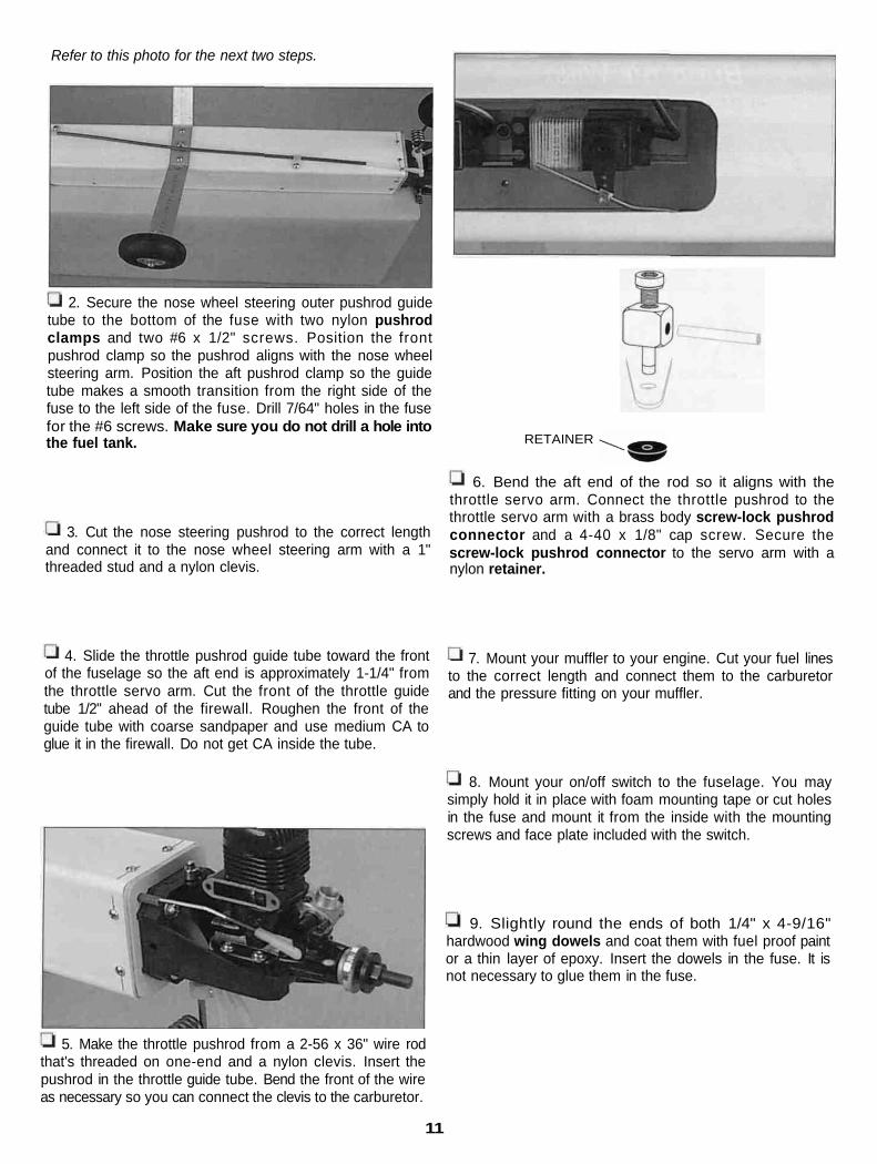
Refer to this photo for the next two steps.
2. Secure the nose wheel steering outer pushrod guidetube to the bottom of the fuse with two nylon pushrodclamps and two #6 x 1/2" screws. Position the frontpushrod clamp so the pushrod aligns with the nose wheelsteering arm. Position the aft pushrod clamp so the guidetube makes a smooth transition from the right side of thefuse to the left side of the fuse. Drill 7/64" holes in the fusefor the #6 screws. Make sure you do not drill a hole intothe fuel tank. RETAINER
6. Bend the aft end of the rod so it aligns with the
3. Cut the nose steering pushrod to the correct lengthand connect it to the nose wheel steering arm with a 1"threaded stud and a nylon clevis.
throttle servo arm. Connect the throttle pushrod to thethrottle servo arm with a brass body screw-lock pushrodconnector and a 4-40 x 1/8" cap screw. Secure thescrew-lock pushrod connector to the servo arm with anylon retainer.
4. Slide the throttle pushrod guide tube toward the frontof the fuselage so the aft end is approximately 1-1/4" fromthe throttle servo arm. Cut the front of the throttle guidetube 1/2" ahead of the firewall. Roughen the front of theguide tube with coarse sandpaper and use medium CA toglue it in the firewall. Do not get CA inside the tube.
7. Mount your muffler to your engine. Cut your fuel linesto the correct length and connect them to the carburetorand the pressure fitting on your muffler.
8. Mount your on/off switch to the fuselage. You maysimply hold it in place with foam mounting tape or cut holesin the fuse and mount it from the inside with the mountingscrews and face plate included with the switch.
hardwood wing dowels and coat them with fuel proof paintor a thin layer of epoxy. Insert the dowels in the fuse. It isnot necessary to glue them in the fuse.
9. Slightly round the ends of both 1/4" x 4-9/16"
5. Make the throttle pushrod from a 2-56 x 36" wire rodthat's threaded on one-end and a nylon clevis. Insert thepushrod in the throttle guide tube. Bend the front of the wireas necessary so you can connect the clevis to the carburetor.
11

1. Mark centerlines on the 1/8" die-cut plywood frontand aft wing joiners. Glue the joiners together with epoxyso centerlines align. If the joiners are slightly warped, gluethem together so the warps cancel out. Lay the joiners on aflat surface and place a weight on top of them to hold themflat until the epoxy cures.
Make a dry run of the following three steps so you cangather all the items you'll need and to make sure youunderstand how to join the wing halves.
Note: We used aliphatic resin (wood worker's glue such asGreat Planes Pro wood glue) to glue the wing together.You may also use 45- or 30-minute epoxy.
3. Lay a sheet of waxed paper over your flat buildingtable that is the same length as your wing (approximately54"). Working quickly, apply glue to the grooves that holdthe main spars in the bottom of both wing halves. Applyglue to the bottom spars. Insert the spars into the notches.Remove excess glue with a paper towel. Hold the bottomspars in place with masking tape so they won't fall out ofthe wing when you turn it upside down. Immediatelyproceed to the next step.
2. Test fit the wing joiner in one of the wing halves.Place a 3/16" x 1/2" x 30" basswood top and bottom sparin the spar notches of the wing. If necessary, sand the topand bottom of the wing joiner to allow the spars to fully seatinto the spar notches so the spars will be flush with the topand bottom surface of the wing.
4. Apply a film of glue to the end of both wing halves.Turn the wing halves over and place them on the waxedpaper over your workbench. Push the wing halves together.
12
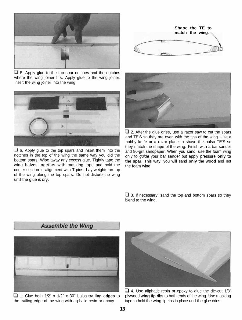
Shape the TE tomatch the wing.
5. Apply glue to the top spar notches and the notcheswhere the wing joiner fits. Apply glue to the wing joiner.Insert the wing joiner into the wing.
6. Apply glue to the top spars and insert them into thenotches in the top of the wing the same way you did thebottom spars. Wipe away any excess glue. Tightly tape thewing halves together with masking tape and hold thecenter section in alignment with T-pins. Lay weights on topof the wing along the top spars. Do not disturb the winguntil the glue is dry.
2. After the glue dries, use a razor saw to cut the sparsand TE'S so they are even with the tips of the wing. Use ahobby knife or a razor plane to shave the balsa TE'S sothey match the shape of the wing. Finish with a bar sanderand 80-grit sandpaper. When you sand, use the foam wingonly to guide your bar sander but apply pressure only tothe spar. This way, you will sand only the wood and notthe foam wing.
3. If necessary, sand the top and bottom spars so theyblend to the wing.
1. Glue both 1/2" x 1/2" x 30" balsa trailing edges tothe trailing edge of the wing with aliphatic resin or epoxy.
4. Use aliphatic resin or epoxy to glue the die-cut 1/8"plywood wing tip ribs to both ends of the wing. Use maskingtape to hold the wing tip ribs in place until the glue dries.
13
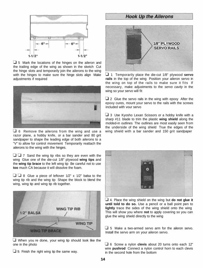
5 Mark the locations of the hinges on the aileron andthe trailing edge of the wing as shown in the sketch Cutthe hinge slots and temporarily join the ailerons to the wingwith the hinges to make sure the hinge slots align Makeadjustments if required
6 Remove the ailerons from the wing and use a
1/8" PLYWOODSERVO RAILS
1 Temporarily place the die-cut 1/8" plywood servorails in the top of the wing Position your aileron servo inthe wing on top of the rails to make sure it f i t s Ifnecessary, make adjustments to the servo cavity in thewing so your servo will fit
2 Glue the servo rails in the wing with epoxy After theepoxy cures, mount your servo to the rails with the screwsincluded with vour servo
3 Use Kyosho Lexan Scissors or a hobby knife with asharp #11 blade to trim the plastic wing shield along themolded-in outlines The outlines are most easily seen fromthe underside of the wing shield True the edges of thewing shield with a bar sander and 150 grit sandpaper
razor plane, a hobby knife, or a bar sander and 80 gritsandpaper to shape the leading edge of both ailerons to a"V" to allow for control movement Temporarily reattach theailerons to the wing with the hinges.
7 Sand the wing tip ribs so they are even with thewing Glue one of the die-cut 1/8" plywood wing tips andthe wing tip brace to the left wing tip Be careful not to usetoo much CA because it will dissolve the foam.
8 Glue a piece of leftover 1/2" x 1/2" balsa to thewing tip rib and the wing tip Shape the block to blend thewing, wing tip and wing tip rib together.
4. Place the wing shield on the wing but do not glue ituntil told to do so. Use a pencil or a ball point pen tolightly trace the sides of the wing shield onto the wingThis will show you where not to apply covering so you canglue the wing shield directly to the wing
5 Make a two-armed servo arm for the aileron servo.Install the servo arm on your aileron servo.
When you re done, your wing tip should look like theone in the photo 6 Screw a nylon clevis about 20 turns onto each 12"
wire pushrod Connect a nylon control horn to each clevisin the second hole from the bottom9. Finish the right wing tip the same way.
14

7 Mount both control horns to the ailerons with two 2 56 3 Bevel the TE of the wing saddle with a bar sanderx 1/2" screws and the mounting plate you cut from thecontrol horn The edge of the horns should be 1/4" from theedge of the ailerons and the control rods should align withthe servo arm
2-56 ( 074") servo HornPushrod Wire
8 Cut the pushrods to the correct length and make a 90degree bend in the end Connect the pushrods to the servoarm with nylon Faslinks
and 150-grit sandpaper so it will not interfere with therubber bands that hold the wing to the fuse.
4 Temporarily mount the wing to the fuselage with two
1. Apply Hobbico" HobbyLite™ filler to any dents or
#64 rubber bands and the wing shield Trim the moldedfront deck along the outlines (seen best from the inside)and sand the edges so they are straight and true Test fitthe front deck to the fuselage and the wing Trim wherenecessary for a good fit Do not mount the front deck to thefuselage until instructed to do so.
molding imperfections in the foam wing After the filler hasdried, use a sanding block and 220-grit sandpaper tocarefully sand the filler, the seam on the leading edge andany other molding irregularities For the best appearance, itis recommended that final sanding be done with 320-gritsandpaper but without a sanding block
2 Test fit the foam wing saddle on the bottom of thewing Cut a hole in the wing saddle to allow the aileronservo cord to pass Use aliphatic resin or epoxy to glue thesaddle to the bottom of the wing, making sure it is centeredand aligned Place a weight on top of the wing to hold it tothe saddle until the glue dries
We presume that the DuraStik will be built by experiencedmodelers but due to its simple, rapid construction, theDuraStik may appeal to beginner modelers as well For newmodelers, or those unfamiliar with finishing techniques, wehave provided some basic information about the coveringmaterials available and the sequence recommended
The foam wing and the balsa surfaces, including theailerons and tail feathers, must be covered with aprotective, fuel proof f inish Among the many modelairplane covering materials available, Top Flite EconoKotefilm or Black Baron film is recommended Both coveringsare applied with a hobby heat seal iron The temperaturerequired to activate the adhesive on some coverings is toohigh to be used over a foam wing Be sure to check thatthe covering you have chosen is for a low-temperatureapplication A low-temperature covering like EconoKotefilm or Black Baron film must be used on the wing.
15

One six foot roll will be enough to cover the DuraStik but, ifyou wish to add trim colors or other designs, you will haveto purchase more than one roll
Covente also offers graphics, numbers, stars and lettering
the tail surfaces and remove the control horns and hingesRemove the stabilizer and fin from the fuselage channel Ifyou haven t already done so, final-sand all the tail surfaceswith 320-grit sandpaper Tip: If you don't mind a little extrawork and would like to have a better looking model with amore finished appearance, taper the ailerons, rudder andelevator by sanding the trailing edges to a thickness ofapproximately 3/32" This is optional and does not effectthe flight performance of your DuraStik.
1 Disconnect the elevator and rudder pushrods from
2 Disconnect the aileron pushrods and remove thecontrol horns from the ailerons Detach the ailerons fromthe wing and remove the hinges
3 Make sure you have final sanded the wing, tailsurfaces and control surfaces.
4 Before covering, remove as much balsa and foamdust as possible left from sanding This can be done withcompressed air, a shop-vac with a brush, or a tack cloth
Now the DuraStik wing and tail feathers are ready to cover.
If you plan to paint any parts of your DuraStik such as thefuselage, landing gear front deck or the wing saddle, nowwould be a good time to do it Use your favorite fuel proofmodel airplane spray paint We recommend Top FliteLustreKote" or Black Baron spray paint.
Follow the instructions included with the covering youhave selected.
Cover the wing in the following order:
1. Bottom of the center section2. Bottom right, then left side3 Top right, then left side4 Ailerons*
* Some modelers cover the ends of the aileronsseparately If you use this method cover the ends first Youcan cover the top and bottom of the ailerons separately orcover them in one piece, wrapping the covering all the wayaround Try to make all seams in the covering face
16

rearward or downward Overlap the lines you drew on thetop of the wing for the wing shield by 1/4" Leave the rest ofthe foam exposed for a good glue bond to the wing shield.
Cover the tail in the following order:
1. Stab bottom, then top2. Elevator3. Fin right, then left side4. Rudder right, then left side
2 Insert the hinges and join the elevator to the stabMake sure there is a very small gap between the TE andthe LE of the control surface This will keep you frominadvertently gluing the controls together If the hinges donot stay centered, insert a pin through the middle of thehinge before you join the surfaces Pull the pin out after thesurfaces are connected.
ASSEMBLE THEN APPLY 6 DROPSOF THIN CA TO CENTER
OF HINGE, ON BOTH SIDES
center of the hinge, on the top and bottom of the stab
4. Hinge the rudder and ailerons the same way.
3. Glue the hinges by applying 6 drops of thin CA to the
1 Start with the stab Slit the covering over the hingeslots Drill a 7/64" hole 1/2" deep in the center of the slotsthat were cut previously This will enable the CA to "wick" intothe hinge. Remove the covering from over the hinge slots.
1 Add strips of 1/4" x 1/16" thick wing seating foamtape to the wing saddle area on the fuselage This will keepthe wing from shifting during flight.
17
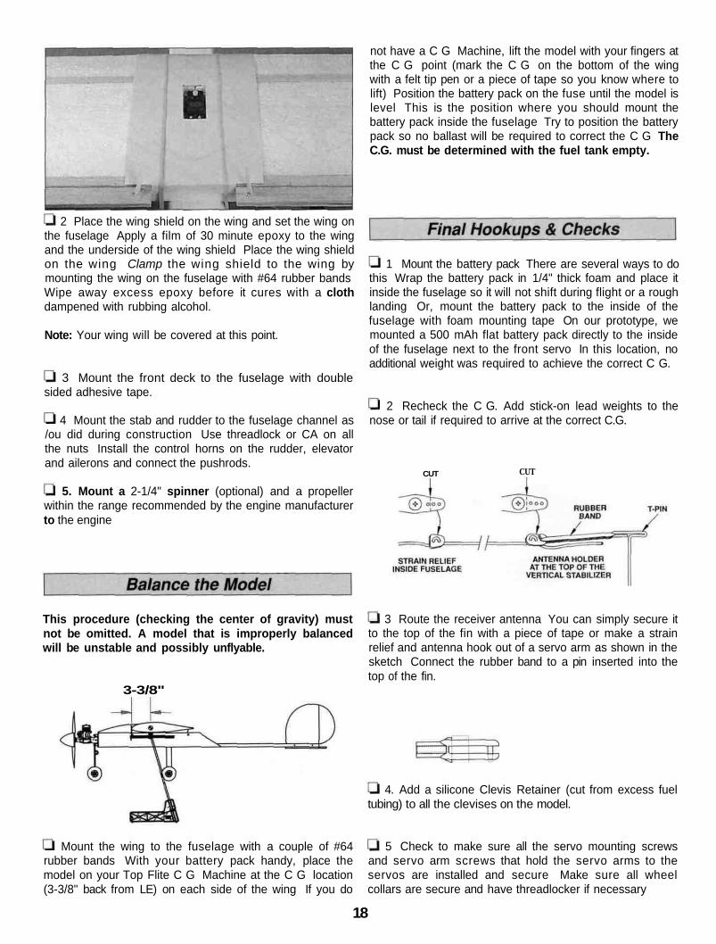
not have a C G Machine, lift the model with your fingers atthe C G point (mark the C G on the bottom of the wingwith a felt tip pen or a piece of tape so you know where tolift) Position the battery pack on the fuse until the model islevel This is the position where you should mount thebattery pack inside the fuselage Try to position the batterypack so no ballast will be required to correct the C G TheC.G. must be determined with the fuel tank empty.
2 Place the wing shield on the wing and set the wing onthe fuselage Apply a film of 30 minute epoxy to the wingand the underside of the wing shield Place the wing shieldon the wing Clamp the wing shield to the wing bymounting the wing on the fuselage with #64 rubber bandsWipe away excess epoxy before it cures with a clothdampened with rubbing alcohol.
Note: Your wing will be covered at this point.
3 Mount the front deck to the fuselage with double
1 Mount the battery pack There are several ways to dothis Wrap the battery pack in 1/4" thick foam and place itinside the fuselage so it will not shift during flight or a roughlanding Or, mount the battery pack to the inside of thefuselage with foam mounting tape On our prototype, wemounted a 500 mAh flat battery pack directly to the insideof the fuselage next to the front servo In this location, noadditional weight was required to achieve the correct C G.
sided adhesive tape.
4 Mount the stab and rudder to the fuselage channel as2 Recheck the C G. Add stick-on lead weights to the
nose or tail if required to arrive at the correct C.G.
CUT CUT
/ou did during construction Use threadlock or CA on allthe nuts Install the control horns on the rudder, elevatorand ailerons and connect the pushrods.
5. Mount a 2-1/4" spinner (optional) and a propellerwithin the range recommended by the engine manufacturerto the engine
This procedure (checking the center of gravity) mustnot be omitted. A model that is improperly balancedwill be unstable and possibly unflyable.
3 Route the receiver antenna You can simply secure itto the top of the fin with a piece of tape or make a strainrelief and antenna hook out of a servo arm as shown in thesketch Connect the rubber band to a pin inserted into thetop of the fin.
3-3/8"
tubing) to all the clevises on the model.4. Add a silicone Clevis Retainer (cut from excess fuel
Mount the wing to the fuselage with a couple of #64 5 Check to make sure all the servo mounting screwsrubber bands With your battery pack handy, place themodel on your Top Flite C G Machine at the C G location(3-3/8" back from LE) on each side of the wing If you do
and servo arm screws that hold the servo arms to theservos are installed and secure Make sure all wheelcollars are secure and have threadlocker if necessary
18

We recommend the following control surface throws.The throws are measured at the trailing edge of theailerons, elevator, and rudder:
2. Balance your propellers. Vibration from an unbalancedpropeller can cause poor engine performance and damageyour in flight radio system. Purchase a Top Flite Power PointMagnetic balancer (TOPQ5700) or a Great Planes FingertipProp Balancer (GPMQ5000) to accurately balanceyour propellers.
3. Make sure the fuel lines are properly connected. Anin-line fuel filter is recommended.
4. Make sure the transmitter and receiver batteries arefully charged.
5. Perform a range check of your radio system asdescribed by the radio manufacturer.
6. When it's time to mount your wing to the fuselageat the flying field, use eight to ten #64 rubberbands.Criss-cross the last two.
High Rate Low Rate
1/4" Up and Down3/8" Up and DownElevator
Ailerons 5/16" Up and Down 3/16" Up and Down
Rudder 1" Left and Right 3/4" Left and Right
Before You Go to the Flying Field
4-CHANNEL RADIO SETUP(STANDARD MODE 2)
ELEVATOR MOVES UP
RIGHT AILERON MOVES UPLEFT AILERON MOVES DOWN
RUDDER MOVES RIGHTNOSE WHEEL TURNS RIGHT
CARBURETOR WIDE OPEN
1. Confirm the direction of the controls.
The DuraPlane DuraStik 40 is intended for intermediate toexpert level pilots although beginners can have success withthe DuraStik if they have had some time on a trainer model.
TAKEOFF: Control throws are not provided for the nosewheel as this varies greatly depending on the conditions ofthe field. More nose steering will be required if taking offfrom a grass field than would be required if taking off froma paved runway. Too much nose wheel throw will make itd i f f icul t to keep the model on heading during rollout - especially if using a paved runway. Move the clevisout one or two holes on the steering arm of the nose gearfor less response.
Unless you are a highly experienced pilot, first flightattempts should be reserved for days when the prevailingwind is calm and down the runway if possible. Advance thethrottle slowly at first, then a little more rapidly apply fullthrottle. Build as much ground speed as your strip willallow, then smoothly apply up elevator until the nose wheelrotates and the airplane lifts into the air. Don't "yank up" onthe stick but relax some of the up elevator and allow theDuraStik to steadily climb to a comfortable altitude beforeexecuting the first turn.
19

FLYING: The DuraStik is a straightforward model with nounexpected tendencies Once airborne, it is a good idea toget the trims corrected before attempting any aerobaticsFly a few straight and level passes, adjusting the trimseach time The most important recommendation we haveis to get used to the feel of the model and the controlrates The recommended throws are relatively mild soexperts will most likely wish to add a little more aileron andelevator throw after becoming familiar with the model Ifthe model seems unstable or reacts too quickly to controlinputs, the C G may be too far aft Add some weight tothe nose if this is the case At a high altitude, throttle backto see how the DuraStik will handle during the slowerlanding approach speeds
LANDING: Make sure you have enough fuel left to make afew landing approaches Use a normal landing circuit andkeep a few clicks of power on until you are over the runwaythreshold Plan to land a little faster on your first fewattempts until you really get the feel of the DuraStik
The DuraStik is a tough "kick around" plane but it does lookrather sporty and is lots of fun to fly. So get carried awayand have a blast'
DuraPlaneP.O. Box 788Urbana,IL61803(217)398-8970
FLIGHT LOGDATE COMMENTS
Started ConstructionFinished ConstructionFirst Flight