Embed Size (px)
Citation preview

Assembly, Installation & Watering Guide
Product Version
Document ID
Gro-Wall® 3.0
01072011/3:28PM/CU
VERTICAL GARDEN SYSTEM
www.atlantiscorp.com.au

2
3
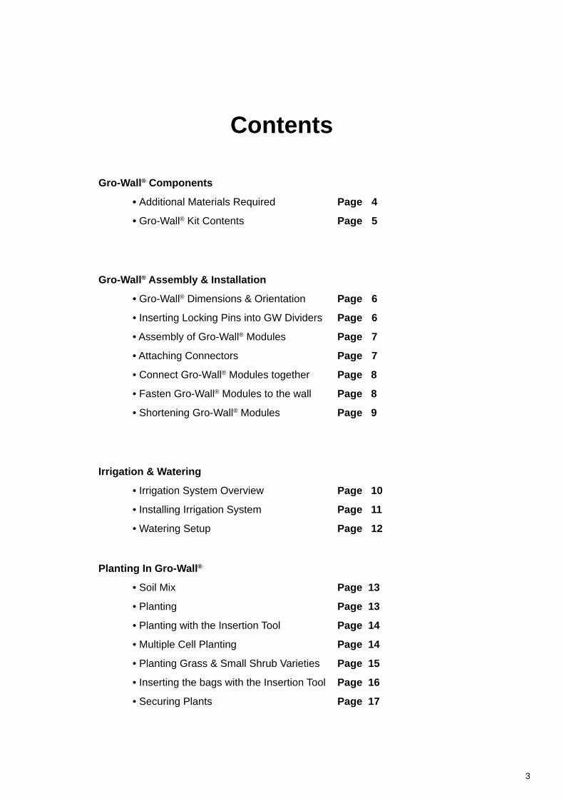
Contents
Gro-Wall® Components
• Additional Materials Required Page 4
• Gro-Wall® Kit Contents Page 5
Gro-Wall® Assembly & Installation
• Gro-Wall® Dimensions & Orientation Page 6
• Inserting Locking Pins into GW Dividers Page 6
• Assembly of Gro-Wall® Modules Page 7
• Attaching Connectors Page 7
• Connect Gro-Wall® Modules together Page 8
• Fasten Gro-Wall® Modules to the wall Page 8
• Shortening Gro-Wall® Modules Page 9
Irrigation & Watering
• Irrigation System Overview Page 10
• Installing Irrigation System Page 11
• Watering Setup Page 12
Planting In Gro-Wall®
• Soil Mix Page 13
• Planting Page 13
• Planting with the Insertion Tool Page 14
• Multiple Cell Planting Page 14
• Planting Grass & Small Shrub Varieties Page 15
• Inserting the bags with the Insertion Tool Page 16
• Securing Plants Page 17
4
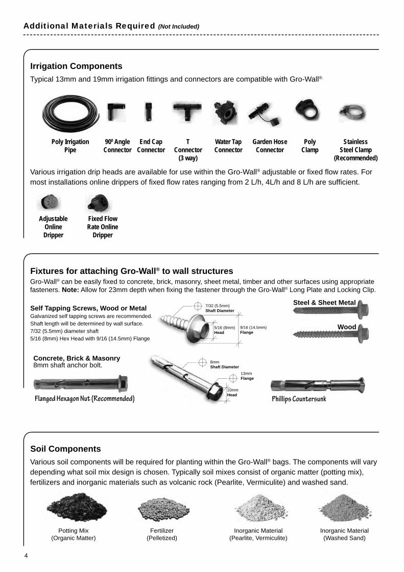
Additional Materials Required (Not Included)
Fixtures for attaching Gro-Wall® to wall structures
Irrigation Components
Soil Components
Gro-Wall® can be easily fi xed to concrete, brick, masonry, sheet metal, timber and other surfaces using appropriate fasteners. Note: Allow for 23mm depth when fi xing the fastener through the Gro-Wall® Long Plate and Locking Clip.
Self Tapping Screws, Wood or MetalGalvanized self tapping screws are recommended. Shaft length will be determined by wall surface. 7/32 (5.5mm) diameter shaft5/16 (8mm) Hex Head with 9/16 (14.5mm) Flange
Concrete, Brick & Masonry 8mm shaft anchor bolt.
Typical 13mm and 19mm irrigation fi ttings and connectors are compatible with Gro-Wall®.
Various irrigation drip heads are available for use within the Gro-Wall® adjustable or fi xed fl ow rates. For most installations online drippers of fi xed fl ow rates ranging from 2 L/h, 4L/h and 8 L/h are suffi cient.
Various soil components will be required for planting within the Gro-Wall® bags. The components will vary depending what soil mix design is chosen. Typically soil mixes consist of organic matter (potting mix), fertilizers and inorganic materials such as volcanic rock (Pearlite, Vermiculite) and washed sand.
Phillips CountersunkFlanged Hexagon Nut (Recommended)
Steel & Sheet Metal
Wood
Potting Mix(Organic Matter)
Fertilizer(Pelletized)
Inorganic Material(Pearlite, Vermiculite)
Inorganic Material(Washed Sand)
Poly Irrigation Pipe
900 AngleConnector
End CapConnector
TConnector
(3 way)
Poly Clamp
StainlessSteel Clamp
(Recommended)
Water Tap Connector
Garden Hose Connector
AdjustableOnline Dripper
Fixed Flow Rate Online
Dripper
5/16 (8mm)Head
7/32 (5.5mm)Shaft Diameter
9/16 (14.5mm)Flange
10mmHead
8mmShaft Diameter
13mmFlange
5
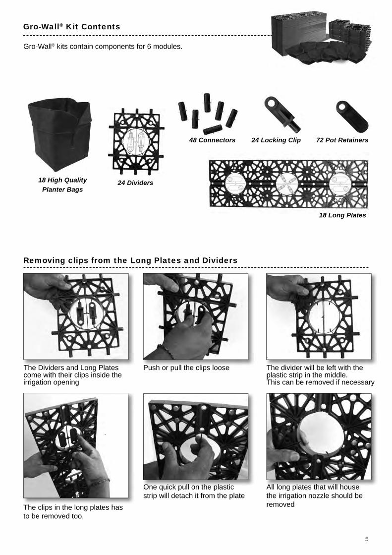
Gro-Wall® Kit Contents
Gro-Wall® kits contain components for 6 modules.
18 High Quality Planter Bags
48 Connectors
24 Dividers
18 Long Plates
24 Locking Clip 72 Pot Retainers
18 Long Plates
Removing clips from the Long Plates and Dividers
One quick pull on the plastic strip will detach it from the plate
All long plates that will house the irrigation nozzle should be removedThe clips in the long plates has
to be removed too.
The Dividers and Long Plates come with their clips inside the irrigation opening
Push or pull the clips loose The divider will be left with the plastic strip in the middle.This can be removed if necessary
6
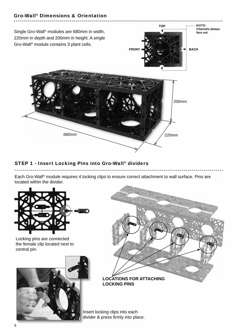
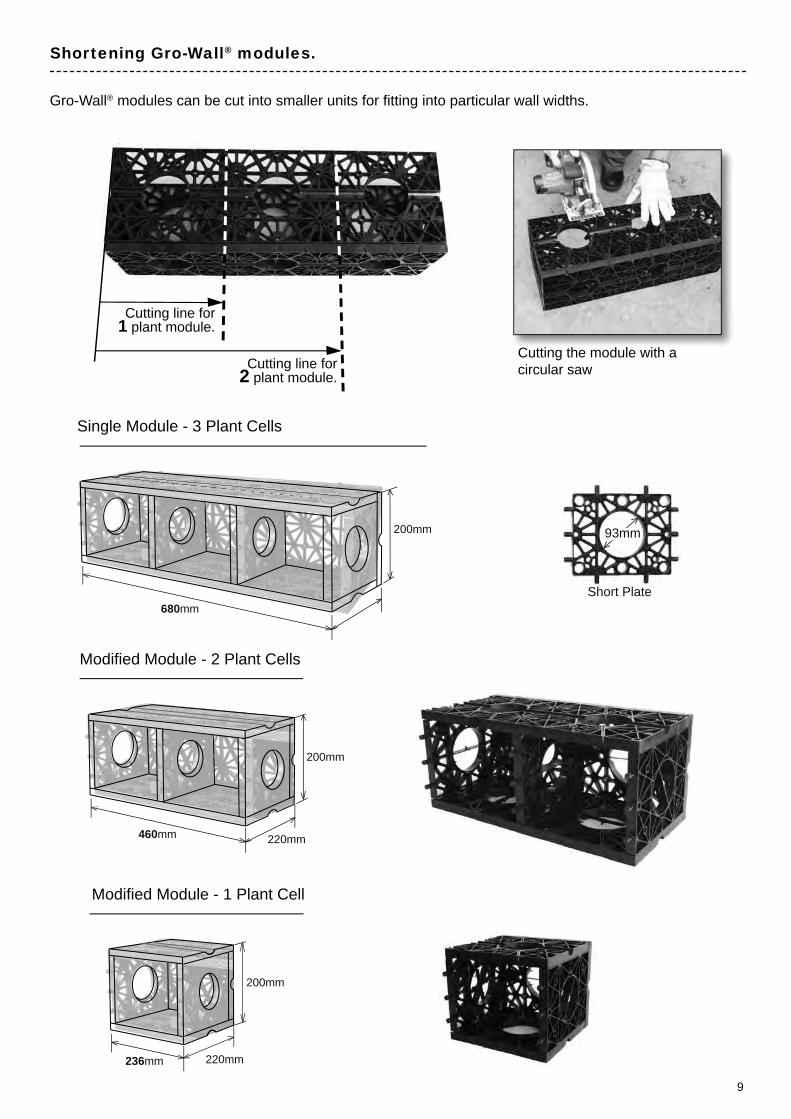
680mm 220mm
200mm
Gro-Wall® Dimensions & Orientation
STEP 1 - Insert Locking Pins into Gro-Wall® dividers
Insert locking clips into each divider & press fi rmly into place.
Each Gro-Wall® module requires 4 locking clips to ensure correct attachment to wall surface. Pins are located within the divider.
Single Gro-Wall® modules are 680mm in width, 220mm in depth and 200mm in height. A single Gro-Wall® module contains 3 plant cells.
LOCATIONS FOR ATTACHINGLOCKING PINS
NOTE: Channels always face out.
FRONT
TOP
BACK
Locking pins are connected the female clip located next to central pin.
7
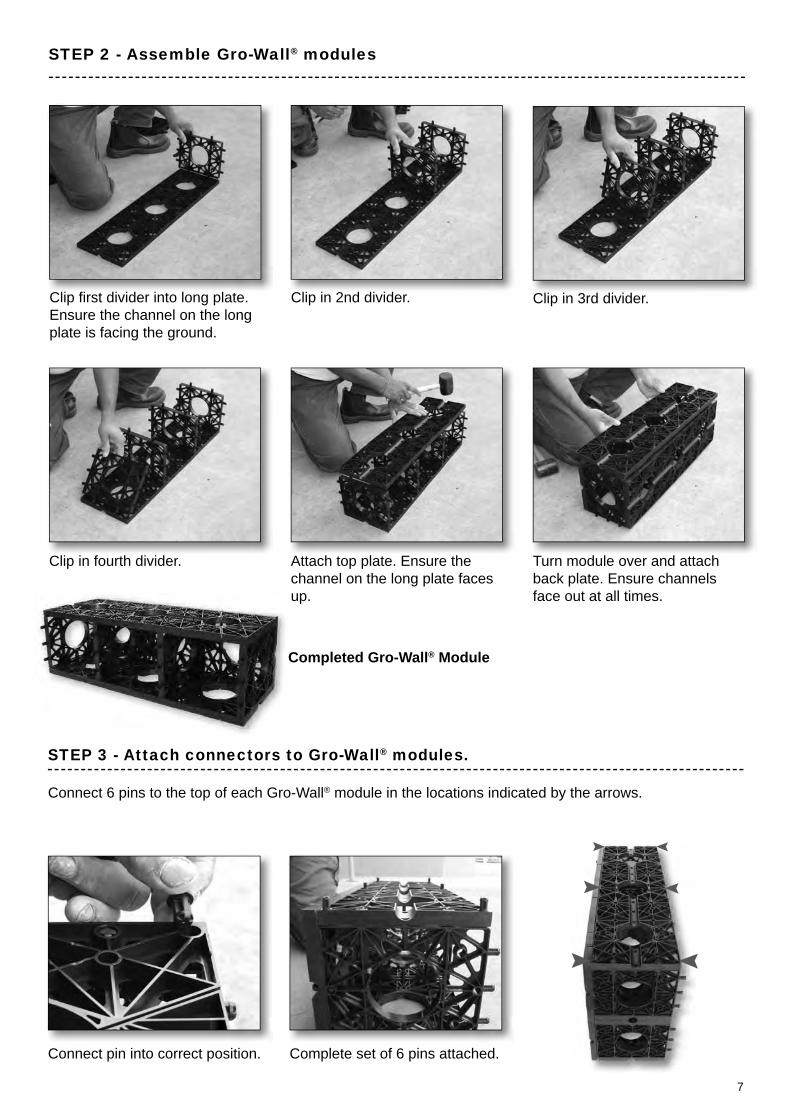
Attach top plate. Ensure the channel on the long plate faces up.
Completed Gro-Wall® Module
Connect 6 pins to the top of each Gro-Wall® module in the locations indicated by the arrows.
STEP 2 - Assemble Gro-Wall® modules
Turn module over and attach back plate. Ensure channels face out at all times.
Clip in 3rd divider.Clip in 2nd divider.
Clip in fourth divider.
Clip fi rst divider into long plate. Ensure the channel on the long plate is facing the ground.
Connect pin into correct position. Complete set of 6 pins attached.
STEP 3 - Attach connectors to Gro-Wall® modules.
8
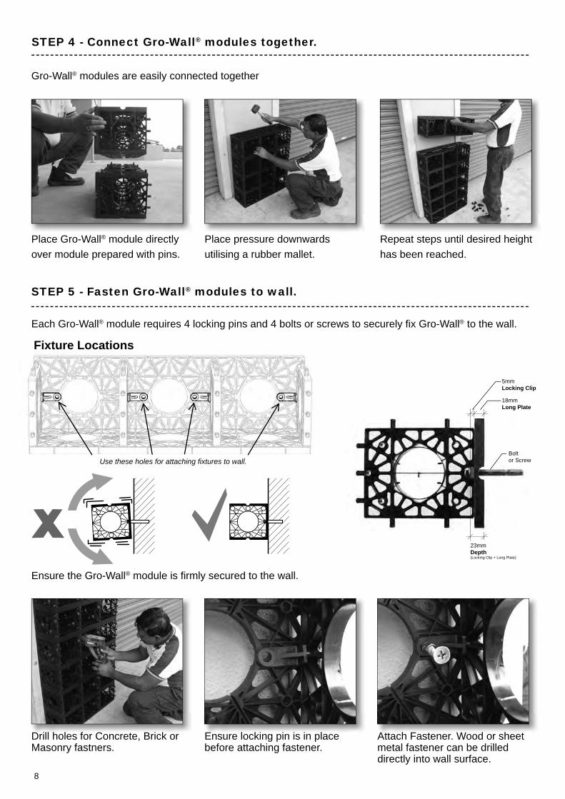
STEP 5 - Fasten Gro-Wall® modules to wall.
Each Gro-Wall® module requires 4 locking pins and 4 bolts or screws to securely fi x Gro-Wall® to the wall.
Gro-Wall® modules are easily connected together
Place Gro-Wall® module directly over module prepared with pins.
Drill holes for Concrete, Brick or Masonry fastners.
Ensure locking pin is in place before attaching fastener.
Attach Fastener. Wood or sheet metal fastener can be drilled directly into wall surface.
Place pressure downwards utilising a rubber mallet.
Repeat steps until desired height has been reached.
Use these holes for attaching fi xtures to wall.
STEP 4 - Connect Gro-Wall® modules together.
Fixture Locations
5mmLocking Clip
18mmLong Plate
Bolt or Screw
23mmDepth(Locking Clip + Long Plate)
Ensure the Gro-Wall® module is fi rmly secured to the wall.
9
Gro-Wall® modules can be cut into smaller units for fi tting into particular wall widths.
Shortening Gro-Wall® modules.
200mm 93mm
Short Plate
Single Module - 3 Plant Cells
680mm
200mm
460mm 220mm
Modifi ed Module - 2 Plant Cells
Modifi ed Module - 1 Plant Cell
200mm
236mm 220mm
Cutting line for 2 plant module.
Cutting line for 1 plant module.
Cutting the module with a circular saw
10
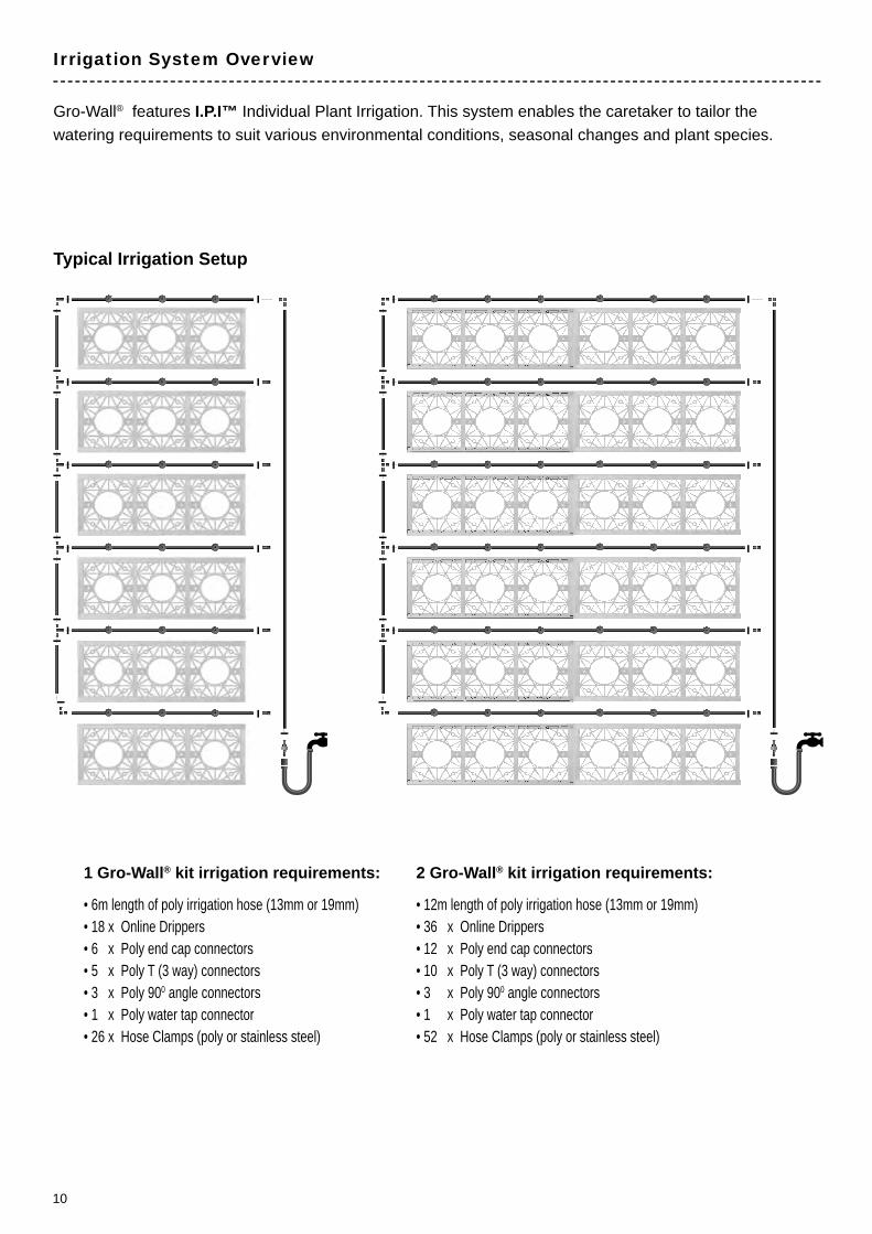
Gro-Wall® features I.P.I™ Individual Plant Irrigation. This system enables the caretaker to tailor the watering requirements to suit various environmental conditions, seasonal changes and plant species.
Irrigation System Overview
Typical Irrigation Setup
• 6m length of poly irrigation hose (13mm or 19mm)• 18 x Online Drippers• 6 x Poly end cap connectors• 5 x Poly T (3 way) connectors• 3 x Poly 900 angle connectors• 1 x Poly water tap connector• 26 x Hose Clamps (poly or stainless steel)
1 Gro-Wall® kit irrigation requirements:
• 12m length of poly irrigation hose (13mm or 19mm)• 36 x Online Drippers• 12 x Poly end cap connectors• 10 x Poly T (3 way) connectors• 3 x Poly 900 angle connectors• 1 x Poly water tap connector• 52 x Hose Clamps (poly or stainless steel)
2 Gro-Wall® kit irrigation requirements:
11
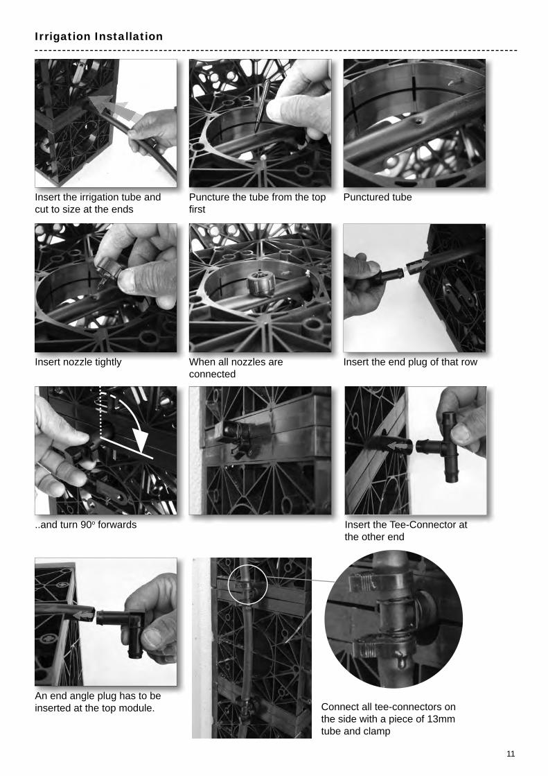
Insert the irrigation tube and cut to size at the ends
Insert nozzle tightly
..and turn 90o forwards Insert the Tee-Connector at the other end
An end angle plug has to be inserted at the top module. Connect all tee-connectors on
the side with a piece of 13mm tube and clamp
Puncture the tube from the top fi rst
When all nozzles are connected
Punctured tube
Insert the end plug of that row
Irrigation Installation

12
Step 1 - Turn on the irrigation system.
Step 3 - Monitor the moisture level within the system. ( A moisture meter is recommended )
Step 4 - When the moisture level within the plant cell reaches optimal moisture conditions switch the irrigation system off.
Step 5 - Continue monitoring the moisture level in the soil mix during the course of the fi rst day and every day afterwards until moisture levels are below optimal.
Step 6 - When the moisture level drops below optimal growing conditions turn on the irrigation system.
Step 7 - Set irrigation timing to this cycle.
Step 8 - Check cycle period. To adjust cycle, repeat process.
Watering Setup
--- After Irrigation --- --- Begin Irrigation Cycle --- --- During irrigation ---
Watering Process within Gro-Wall®
During watering of the Gro-Wall® system each plant cell will absorb water via the online dripper. If the plant cell reaches saturation point the excess water will drain out the bottom of the plant cell. Any excess water drained from one plant cell will also irrigate the plant cell beneath. When the irrigation system is switched off the excess water will drain out of the system during the course of the day.
The moisture levels in the soil mix will change over time due to the following; • Seasonal Changes • Hot & Cold Weather • Wind Conditions • Water Consumption by Plant • Air Humidity
The setup of the irrigation cycle will vary for each installation. Factors that will affect the irrigation cycle and moisture retention within each plant cell are; Seasonal Changes, Hot or Cold Weather, Wind, Air Humidity and Water Consumption by Plants.
m.
Moisture Meter
Watering Procedure for Gro-Wall®
To Set Up Irrigation Cycle Timing

13
Soil Mix
Planting
0o
90o
45o
67.5o
45o
When designing a soil mix for the planter bags it is important to take into consideration the selected plant species and environmental conditions the Gro-Wall® will be installed into. Ideal soil mixes will ensure optimum growing conditions for selected plant species during seasonal changes. Other considerations include reducing weight for structural considerations, providing additional moisture retention, drainage and inorganic material for long term stability.
Gro-Wall® kits contain square planter bags made from a thick grade high quality geotextile. The Gro-Wall® planter bags provide excellent drainage and moisture retention for optimal plant growth. Plants can be planted at various angles ranging from 450 to 900. The planter bag design allows easy access, maintenance and permits watering directly into the soil mix.
0o
90o
45o
67.5o
90 o
Typical Soil Mix’s Confi gurations for Gro-Wall® (Ratio’s between components are confi gured for the specifi c application) • Small Domestic Applications - Premium Potting Mix, Washed Sand, Fertiliser • Long Term Applications - Premium Organic Mix, Washed Sand, Lightweight Volcanic Rock, Fertiliser
Planting at angles
Horizontal Planting
A.
B.

14
Planting with the Insertion Tool
Step 1 - Place the bag into the Insertion Tool. Add soil mix to the base of bag.
Step 2 - Position plant into place. When planting at an angle create a compacted ramp before placing plant.
St 2 P iti l t i t l Step 3 - Add soil mix.
Step 4 - Lift and shake the bag to settle the soil mix.
Step 5 - Add more soil mix, then compact.
Step 6 - Press and compact the bag.Leave an opening at the top by folding the edges.
Step 4 - Closed bag. Step 5 - Open the fl aps of the bag before inserting into module to allow irrigation to water into soil directly.
Step 1 - Remove plant from pot and place it in the bag.
Step 2 - Add additional soil and other components.
Step 3 - Fold the top of the bag.
Planting (Continued)
The Gro-Wall® insertion tool is an optional item available from the Atlantis website www.atlantiscorp.com.au
15
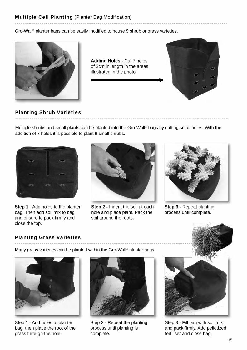
Step 1 - Add holes to planter bag, then place the root of the grass through the hole.
Step 2 - Repeat the planting process until planting is complete.
Step 3 - Fill bag with soil mix and pack fi rmly. Add pelletized fertiliser and close bag.
Planting Grass Varieties
Step 1 - Add holes to the planter bag. Then add soil mix to bag and ensure to pack fi rmly and close the top.
Step 2 - Indent the soil at each hole and place plant. Pack the soil around the roots.
Step 3 - Repeat planting process until complete.
Planting Shrub Varieties
Multiple Cell Planting (Planter Bag Modifi cation)
Multiple shrubs and small plants can be planted into the Gro-Wall® bags by cutting small holes. With the addition of 7 holes it is possible to plant 9 small shrubs.
Gro-Wall® planter bags can be easily modifi ed to house 9 shrub or grass varieties.
Many grass varieties can be planted within the Gro-Wall® planter bags.
Adding Holes - Cut 7 holes of 2cm in length in the areas illustrated in the photo.
16
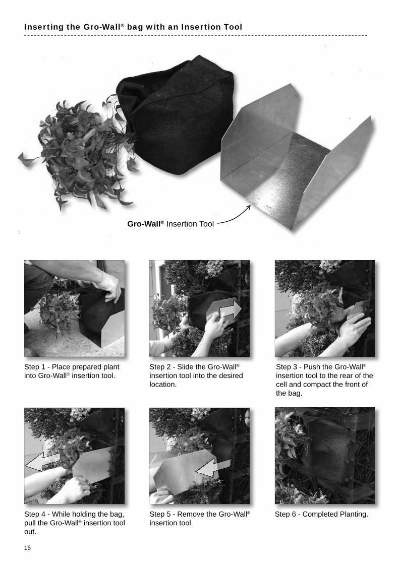
Step 1 - Place prepared plant into Gro-Wall® insertion tool.
Step 3 - Push the Gro-Wall® insertion tool to the rear of the cell and compact the front of the bag.
Inserting the Gro-Wall® bag with an Insertion Tool
Step 4 - While holding the bag, pull the Gro-Wall® insertion tool out.
Step 5 - Remove the Gro-Wall® insertion tool.
Step 6 - Completed Planting.
Step 2 - Slide the Gro-Wall® insertion tool into the desired location.
Gro-Wall® Insertion Tool

17
Additional Plant Securing for High Wind Areas (Option 1)
Additional Plant Securing for High Wind Areas & Vandalism Prevention (Option 2)
Using Gro-Wall® Plant Retainer Clips
Use plastic coated galvanized wire 1mm or 2mm for high wind areas or installations over 3 metres.
Note: Additional Gro-Wall® Long Plates will be required. When used as an anti vandalism measure, cable ties (Zip Ties) or 1mm wire can be used to additionally secure the face plate to the Gro-Wall® module.
A maximum of 4 Gro-Wall® Plant Retainer Clips are used to secure planter bags within the modules.
Click the Plant Retainers in place. 4 Plant Retainer clips can used for each plant cell.
PLANT PLANT PLANT
Feed wire through the Gro-Wall® plate.
Twist and tension the wire.Create a loop around the center of the plant.Create a loop around the center
Position the Face Plate under the plants.
Attach the Face Plate at the front of the module.
Use a rubber mallet to click Face Plate into place.
Cut along the double grooves as indicated in the illustration to convert a Long Plate into a Face Plate.
Cutting the opening.

18
Notes:
19
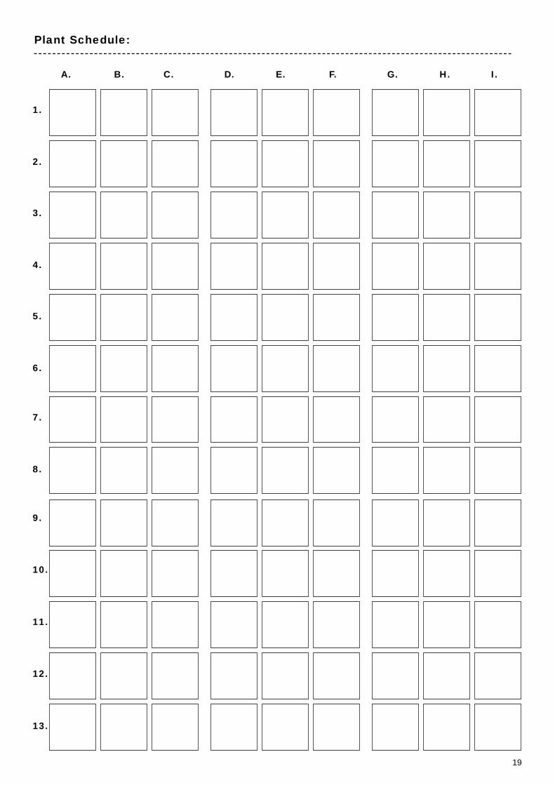
Plant Schedule:
1.
3.
5.
7.
9.
11.
2.
4.
6.
8.
10.
12.
13.
A. B. C. D. E. F. G. H. I.
20
PHONE: + 612 9417 8344FAX: + 612 9417 8311EMAIL: [email protected]: www.atlantiscorp.com.au
Atlantis Water ManagementNote: Atlantis® products are manufactured from high quality recycled materials, carefully selected and under strict quality control procedures. The strength could vary slightly due to raw material, country of manufacture, manufacturing process and external conditions. All trademarks are the property of Atlantis Water Management Australia.
Disclaimer: All information provided in this publication is correct to the best knowledge of the company and is given out in good faith. This information is intended only as a general guide, no responsibility can be accepted for any errors, omissions or incorrect assumption. As each project is unique, and as Rebirth Pty Ltd, Atlantis Water Management, Atlantis Corporation Pty Ltd and its distributors and agents world wide have no direct control over the methods employed by the user in specifying, installing or supervising of its products hence no responsibility is accepted by Rebirth Pty Ltd, Atlantis Water Management, Atlantis Corporation Pty Ltd and its distributors and agents world wide. Users should satisfy themselves as to the suitability of the product for their purpose.
All product designs, and specifi cation are subject to change without further notice. All Atlantis® products are tested in approved laboratories, and safe allowed tolerances should be practised in the actual fi eld, to compensate for any unforeseen situations, on site and on products.
VERTICAL GARDEN SYSTEM