Embed Size (px)
DESCRIPTION
Assembly Hall in Hybrid-A’ and ILD. 2014/9/6 Yasuhiro Sugimoto. Assembly hall for ILD. Five pieces of ILD yoke (YE-, YB-, YB0, YB+, YE+) are assembled in the surface assembly hall (AH) - PowerPoint PPT Presentation
Citation preview
Assembly Hall in Hybrid-A’ and ILD
2014/9/6
Yasuhiro Sugimoto
1
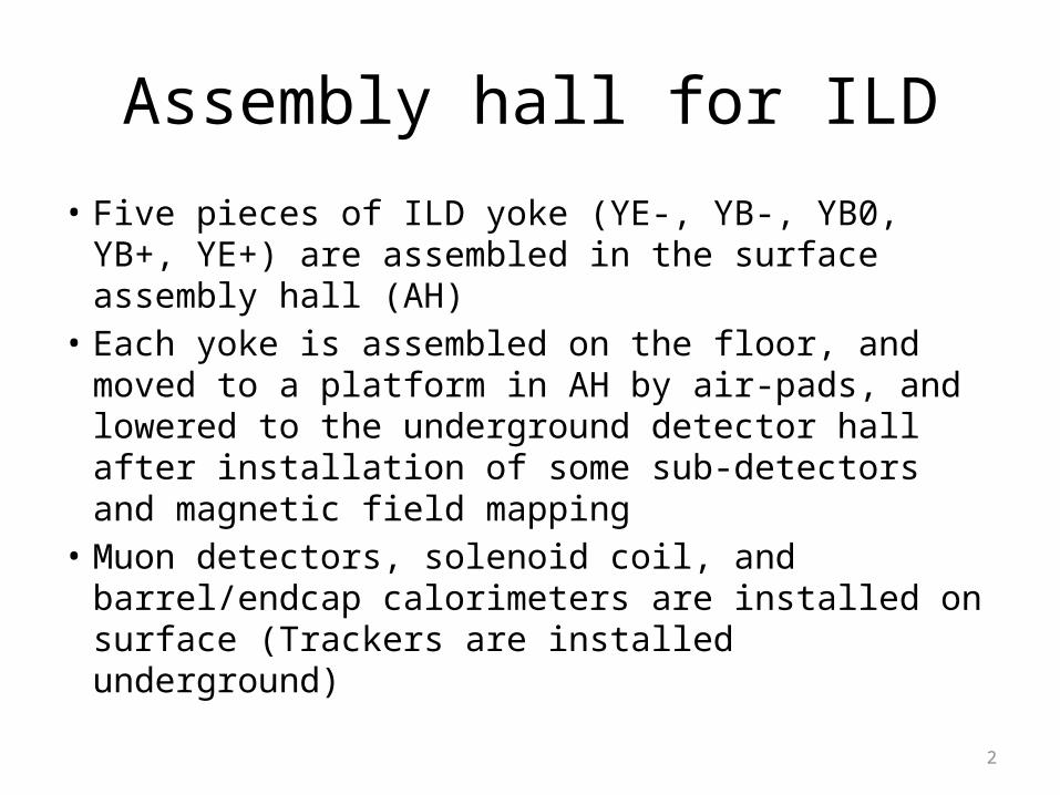
Assembly hall for ILD
• Five pieces of ILD yoke (YE-, YB-, YB0, YB+, YE+) are assembled in the surface assembly hall (AH)
• Each yoke is assembled on the floor, and moved to a platform in AH by air-pads, and lowered to the underground detector hall after installation of some sub-detectors and magnetic field mapping
• Muon detectors, solenoid coil, and barrel/endcap calorimeters are installed on surface (Trackers are installed underground)
2
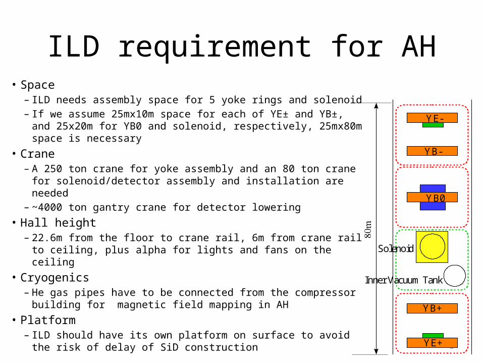
ILD requirement for AH• Space
– ILD needs assembly space for 5 yoke rings and solenoid – If we assume 25mx10m space for each of YE± and YB±, and
25x20m for YB0 and solenoid, respectively, 25mx80m space is necessary
• Crane– A 250 ton crane for yoke assembly and an 80 ton crane for
solenoid/detector assembly and installation are needed– ~4000 ton gantry crane for detector lowering
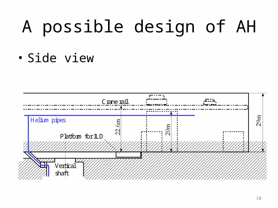
• Hall height– 22.6m from the floor to crane rail, 6m from crane rail to ceiling,
plus alpha for lights and fans on the ceiling
• Cryogenics– He gas pipes have to be connected from the compressor
building for magnetic field mapping in AH
• Platform– ILD should have its own platform on surface to avoid the risk
of delay of SiD construction3
YB0
YE+
YE-
YB+
YB-
Solenoid
Inner Vacuum Tank
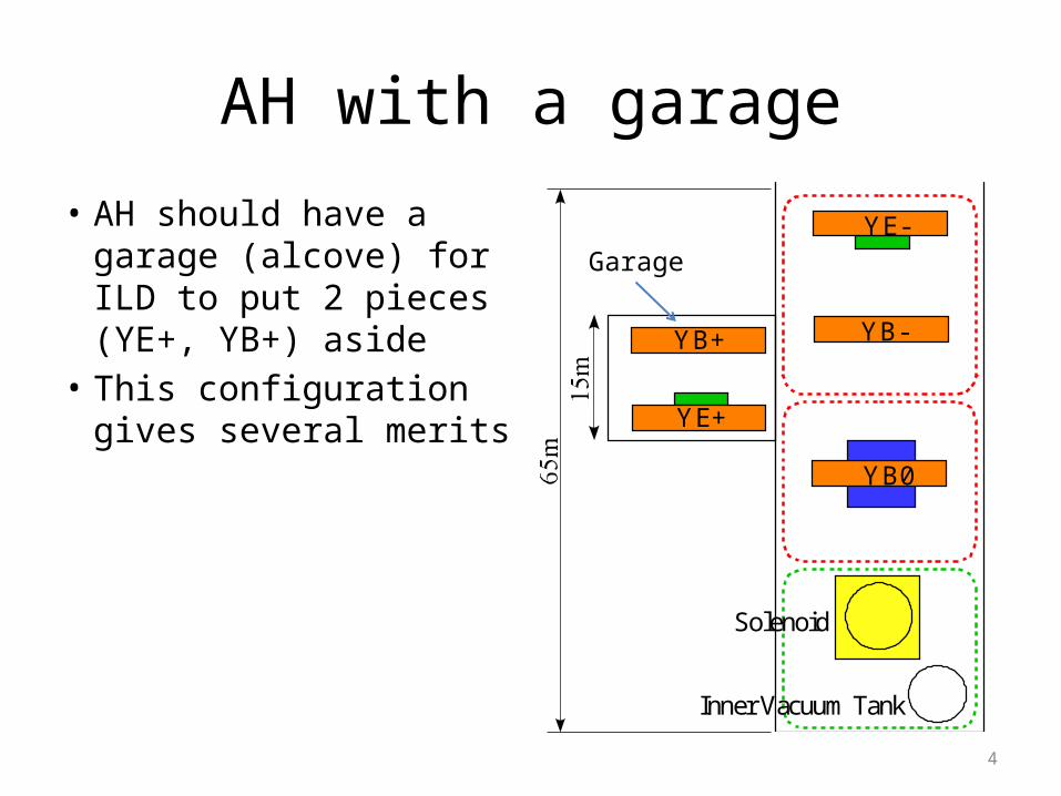
AH with a garage
• AH should have a garage (alcove) for ILD to put 2 pieces (YE+, YB+) aside
• This configuration gives several merits
4
Solenoid
Inner Vacuum Tank
YB0
YE-
YB-
YE+
YB+
Garage
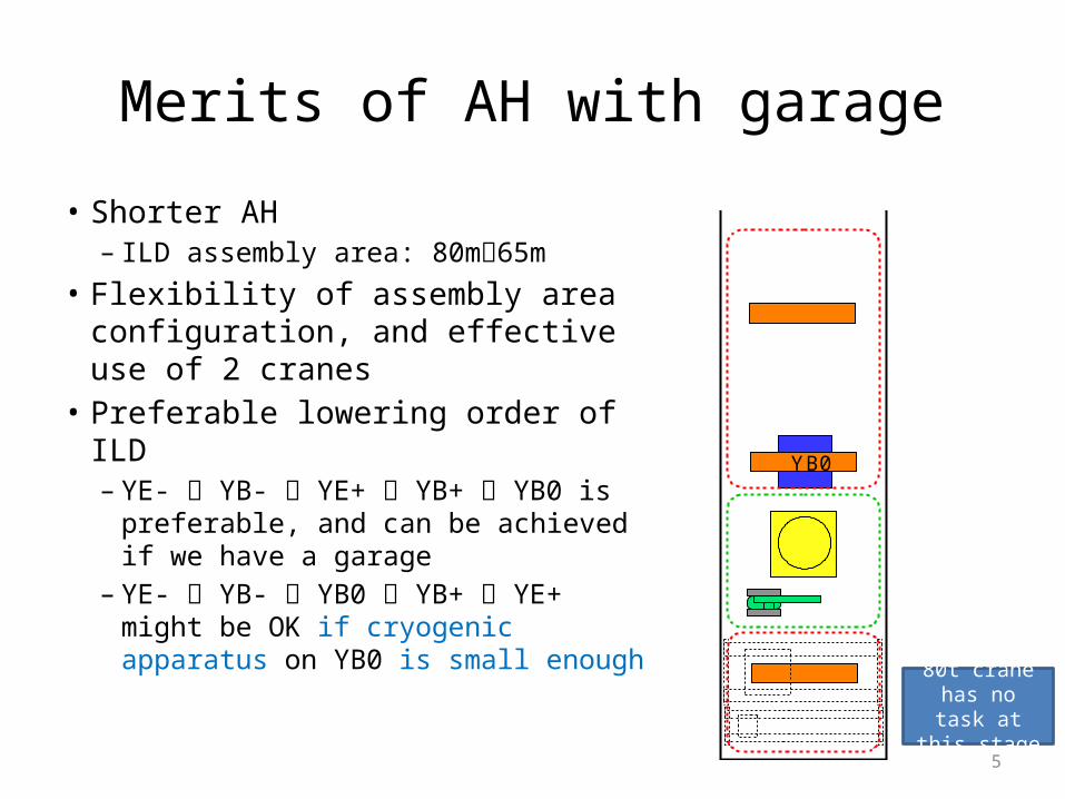
Merits of AH with garage
• Shorter AH– ILD assembly area: 80m65m
• Flexibility of assembly area configuration, and effective use of 2 cranes
• Preferable lowering order of ILD– YE- YB- YE+ YB+ YB0 is
preferable, and can be achieved if we have a garage
– YE- YB- YB0 YB+ YE+ might be OK if cryogenic apparatus on YB0 is small enough
5
80t crane has no task at this stage
YB0
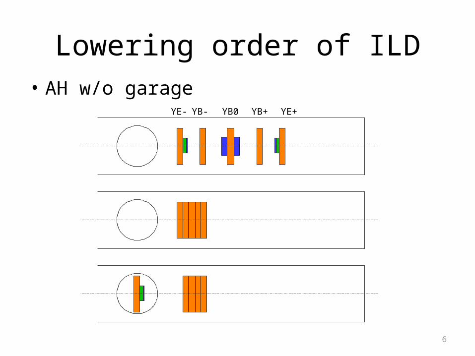
Lowering order of ILD• AH w/o garage
6
YE- YB- YB0 YB+ YE+
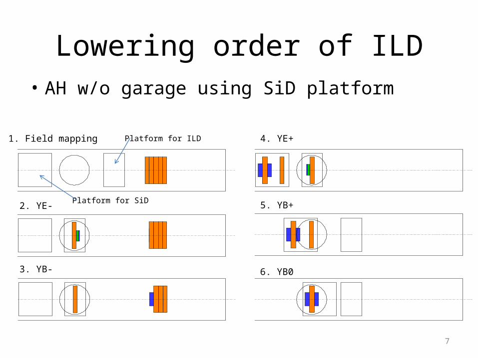
Lowering order of ILD• AH w/o garage using SiD platform
7
1. Field mapping
2. YE-
3. YB-
4. YE+
5. YB+
6. YB0
Platform for ILD
Platform for SiD
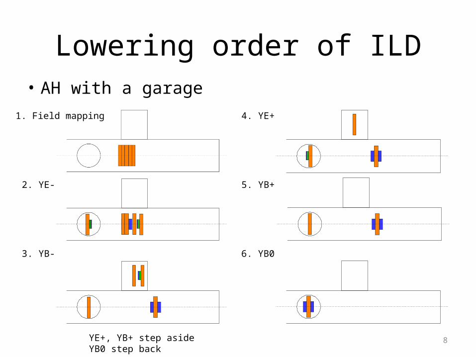
• AH with a garage
8
Lowering order of ILD
1. Field mapping
2. YE-
3. YB-
4. YE+
5. YB+
6. YB0
YE+, YB+ step asideYB0 step back
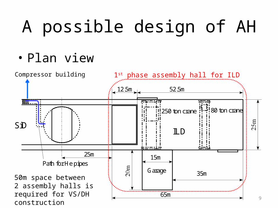
A possible design of AH
• Plan viewCompressor building
965m
52.5m
35m
15m
ILDSiD
Path for He pipesGarage
80 ton crane250 ton crane
12.5m
25m
1st phase assembly hall for ILD
50m space between 2 assembly halls is required for VS/DHconstruction
A possible design of AH
• Side view
10
Platform for ILD
Verticalshaft
Crane rail
Helium pipes
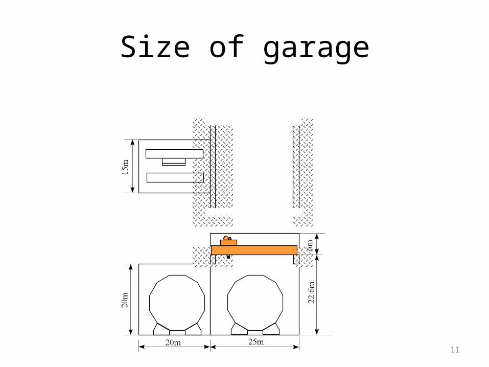
Size of garage
11
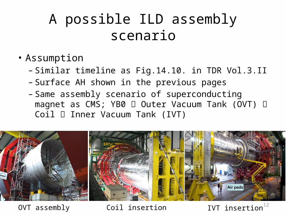
A possible ILD assembly scenario
• Assumption– Similar timeline as Fig.14.10. in TDR Vol.3.II– Surface AH shown in the previous pages– Same assembly scenario of superconducting magnet
as CMS; YB0 Outer Vacuum Tank (OVT) Coil Inner Vacuum Tank (IVT)
OVT assembly Coil insertion IVT insertion 12
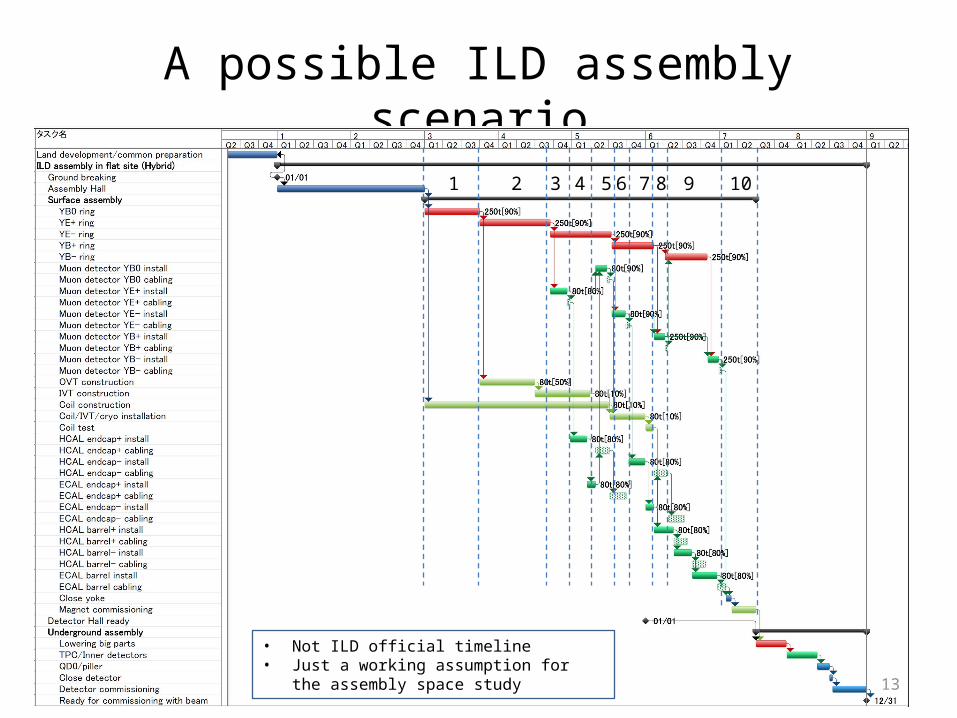
A possible ILD assembly scenario
1 32 4 5 6 7 98 10
13
• Not ILD official timeline• Just a working assumption for the assembly
space study
YB0
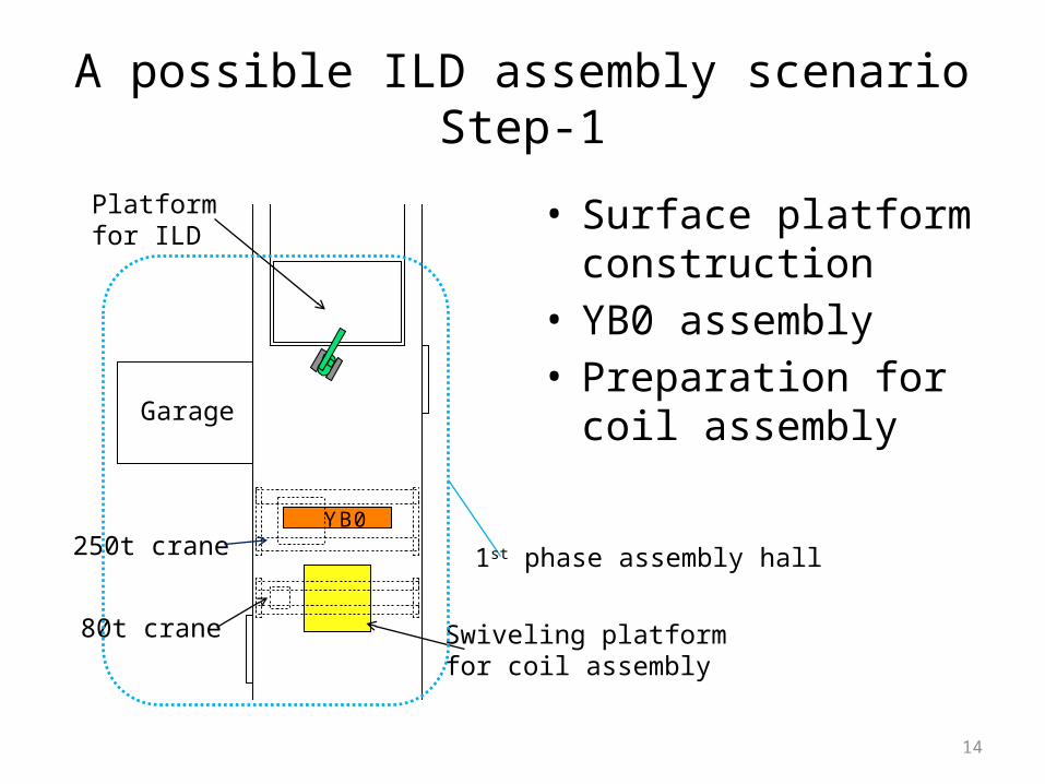
A possible ILD assembly scenarioStep-1
• Surface platform construction
• YB0 assembly• Preparation for coil
assembly
250t crane
80t crane
14
Swiveling platformfor coil assembly
Platformfor ILD
Garage
1st phase assembly hall
YB0
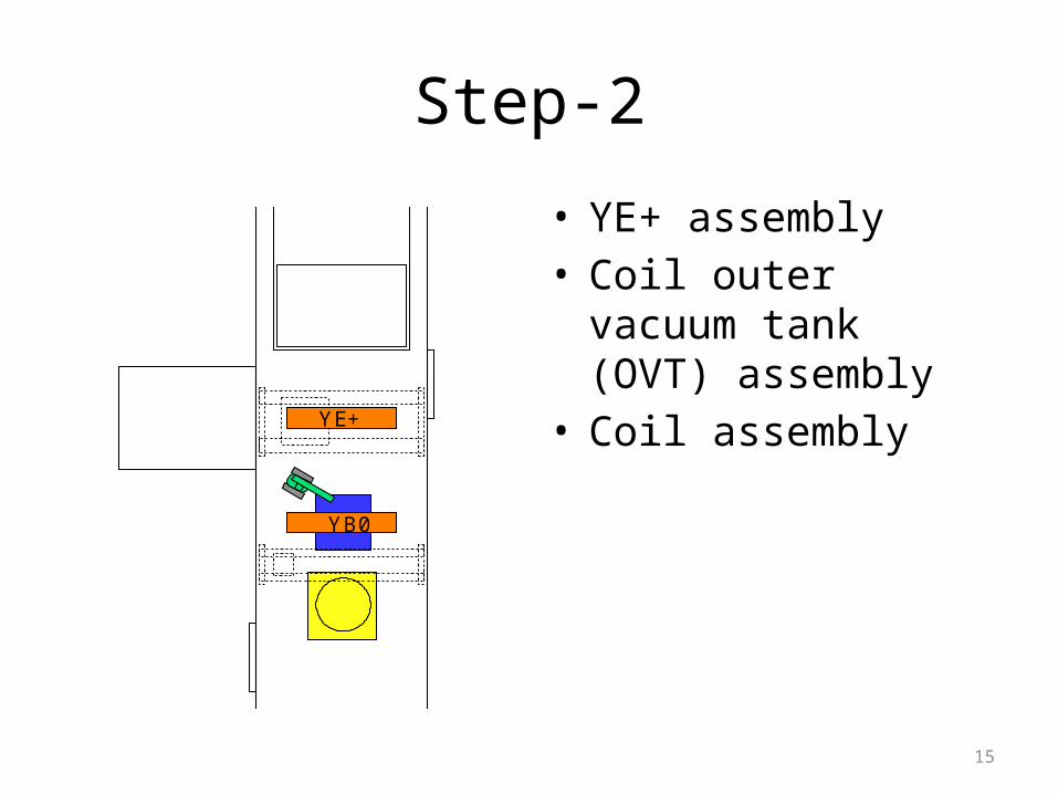
YE+
Step-2
• YE+ assembly• Coil outer vacuum
tank (OVT) assembly• Coil assembly
15
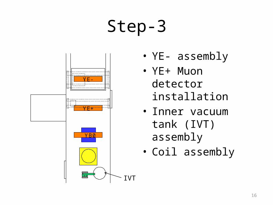
Step-3
• YE- assembly• YE+ Muon detector
installation• Inner vacuum tank
(IVT) assembly• Coil assembly
16
IVT
YB0
YE+
YE-
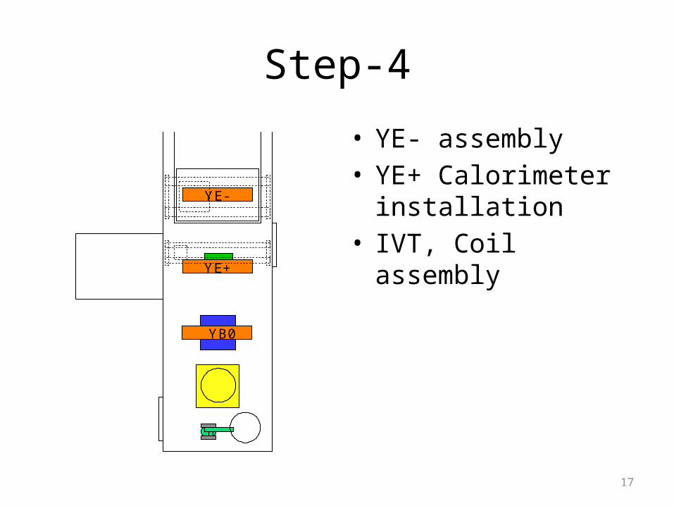
Step-4
• YE- assembly• YE+ Calorimeter
installation• IVT, Coil assembly
17
YB0
YE+
YE-
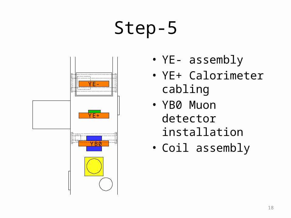
Step-5
• YE- assembly• YE+ Calorimeter
cabling• YB0 Muon detector
installation• Coil assembly
18
YB0
YE+
YE-
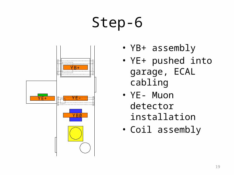
Step-6
• YB+ assembly• YE+ pushed into
garage, ECAL cabling• YE- Muon detector
installation• Coil assembly
19
YB0
YE+ YE-
YB+
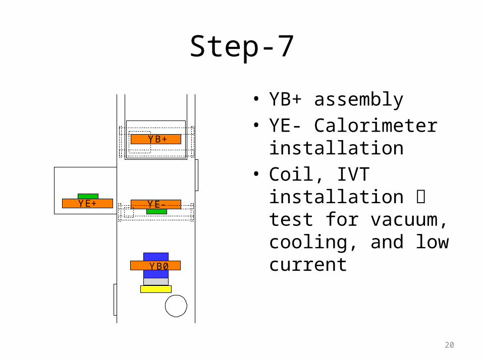
Step-7
• YB+ assembly• YE- Calorimeter
installation• Coil, IVT installation
test for vacuum, cooling, and low current
20
YE+ YE-
YB+
YB0
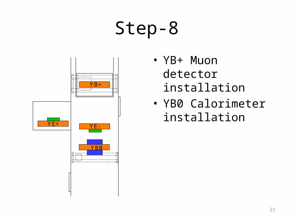
Step-8
• YB+ Muon detector installation
• YB0 Calorimeter installation
21
YE+ YE-
YB+
YB0
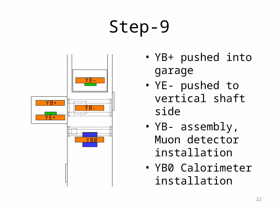
Step-9
• YB+ pushed into garage
• YE- pushed to vertical shaft side
• YB- assembly, Muon detector installation
• YB0 Calorimeter installation
22
YB0
YE+
YE-
YB+YB-
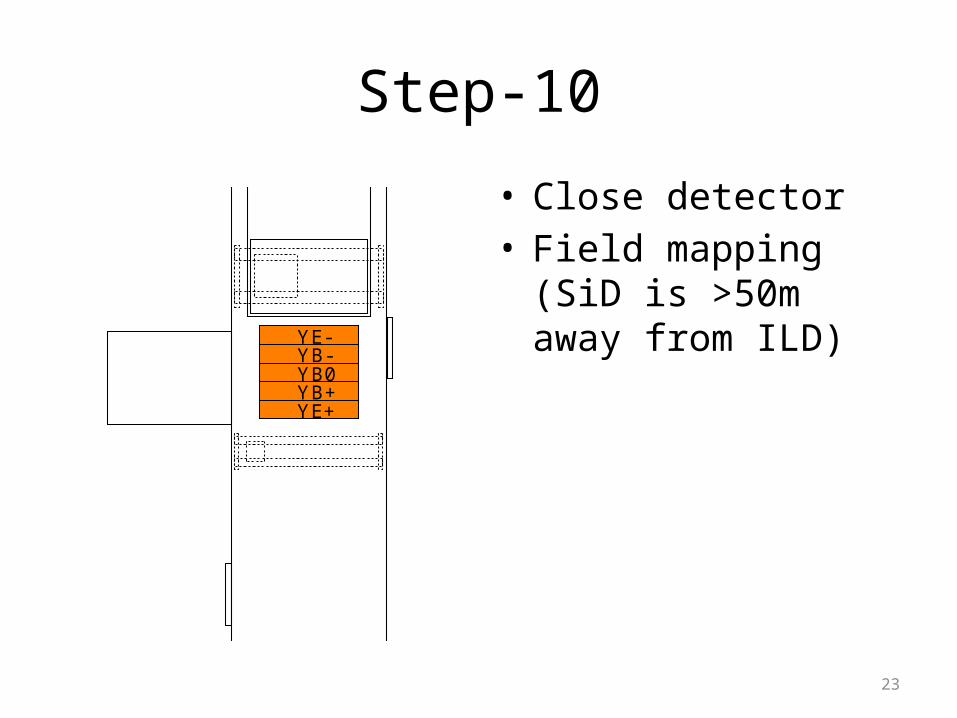
Step-10
• Close detector• Field mapping (SiD is
>50m away from ILD)
23
YB0
YE+
YE-
YB+
YB-
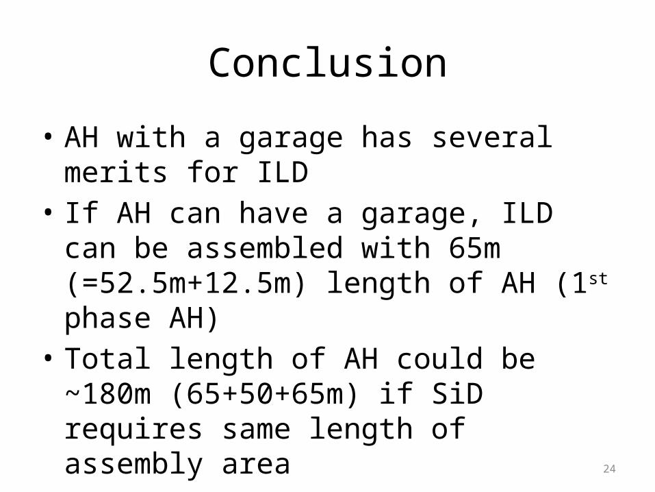
Conclusion
• AH with a garage has several merits for ILD
• If AH can have a garage, ILD can be assembled with 65m (=52.5m+12.5m) length of AH (1st phase AH)
• Total length of AH could be ~180m (65+50+65m) if SiD requires same length of assembly area
24