Embed Size (px)
Citation preview

1 De-pressurize the line in compliance withstanding instructions AWAYS PROCEED WITH CAUTION !Never take it for granted that the line has been de-pressurized. Re-pressurization of the line prior to or during disassembly is possible for many reasons.
REFER TO THE RELEVANT HEALTH AND SAFETY INSTRUCTIONS FOR PROTECTIVE MEASURES.
2 Start loosening the bolts gradually with steps of maximum 60 degrees rotation in each step in relevant criss-cross pattern Continue this pattern until you are able to verify that the seal is broken and the sealring is loose. When you are satisfied that the seal is broken, proceed to loosen bolts further and remove bolts necessary to retrieve sealring.
DISASSEMBLY PROCEDURE
12
1 2
1 2
12
14
2 3
1 4
23
Bolting sequence criss-cross patternEx. 2 - using 2 tools
Bolting sequence criss-cross pattern (Ex. 1 - using 4 tools)
FABRICATION - “Respect & Protect”
1 Respect sealing surfaces • DO NOT use chains through flange bores or bolt holes. • DO NOT allow weld spatter to damage sealing surfaces.• DO NOT use earthing clamps on sealing surfaces. • TAKE CARE when inserting and removing items through bore.• Polish sealing surfaces after heat treatment.
2 Protect sealing surfaces • Protect seats during and after fabrication. • Apply anti-corrosion protection where necessary and re-fit.
3 Corrosion protection Vector SPO® Compact Flanges and bolts are supplied with various protective coatings. Additional corrosion protection may be required on assembled flanges to suit environmental conditions and/or to rectify coating damage during assembly.
ENVECTOR SPO® COMPACT FLANGE
ASSEMBLY - DISASSEMBLYPOCKET GUIDE
Australia (Perth) +61 8 9324 3880
Brazil (Rio De Janeiro) +55 11 2176 2300
Malaysia (Kuala Lumpur) +603 8723 3689
Norway (Drammen) +47 32 20 93 00
UK (Aberdeen) +44 1224 775 242
UK (Port Talbot) +44 1639 822 555
USA (Houston) +1 713 979 4444
© 2016 Freudenberg Oil & Gas Technologies. All rights reserved.Vector SPO® Compact Flange is a registered trademark of FO>.
www.fogt.comV005-03-2016
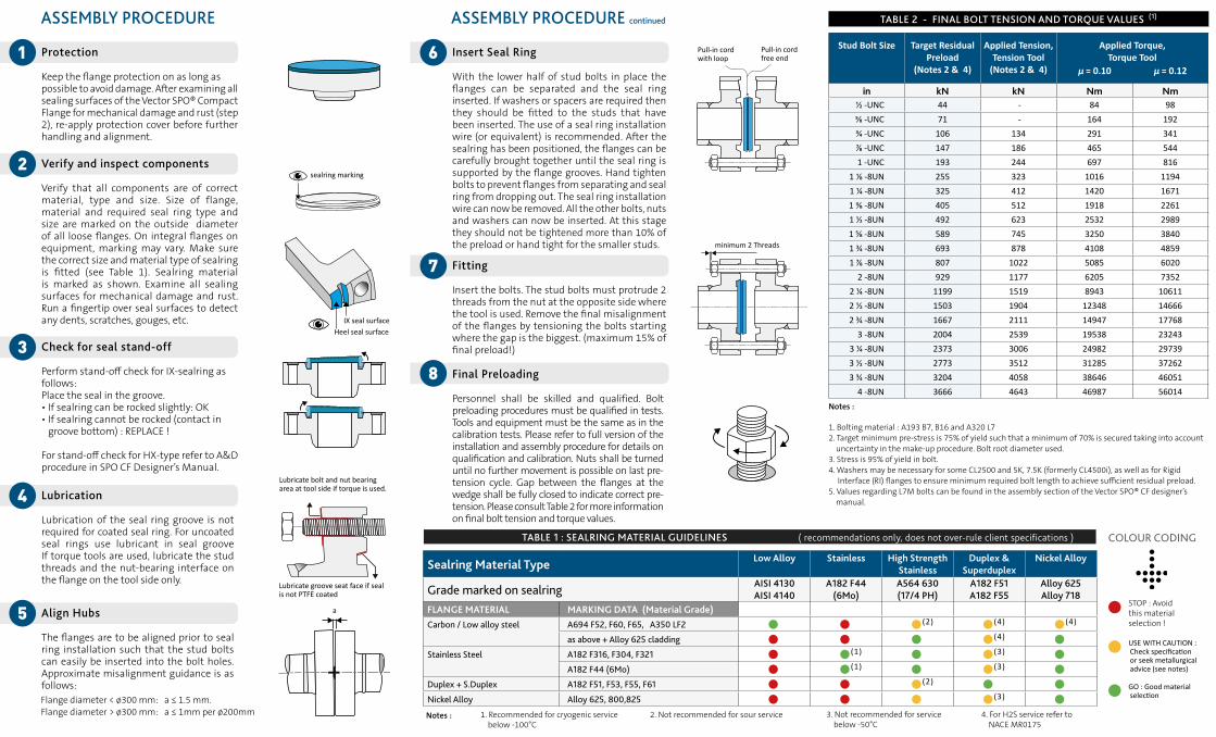
7 Fitting
Insert the bolts. The stud bolts must protrude 2 threads from the nut at the opposite side where the tool is used. Remove the final misalignment of the flanges by tensioning the bolts starting where the gap is the biggest. (maximum 15% of final preload!)
minimum 2 Threads
Stud Bolt Size Target ResidualPreload
(Notes 2 & 4)
Applied Tension, Tension Tool
(Notes 2 & 4)
Applied Torque,Torque Tool
μ = 0.10 μ = 0.12
in kN kN Nm Nm1/2 -UNC 44 - 84 985/8 -UNC 71 - 164 1923/4 -UNC 106 134 291 341⅞ -UNC 147 186 465 5441 -UNC 193 244 697 816
1 ⅛ -8UN 255 323 1016 11941 1/4 -8UN 325 412 1420 16711 ⅜ -8UN 405 512 1918 22611 1/2 -8UN 492 623 2532 29891 5/8 -8UN 589 745 3250 38401 3/4 -8UN 693 878 4108 48591 7/8 -8UN 807 1022 5085 6020
2 -8UN 929 1177 6205 73522 1/4 -8UN 1199 1519 8943 106112 1/2 -8UN 1503 1904 12348 146662 3/4 -8UN 1667 2111 14947 17768
3 -8UN 2004 2539 19538 232433 1/4 -8UN 2373 3006 24982 297393 1/2 -8UN 2773 3512 31285 372623 3/4 -8UN 3204 4058 38646 46051
4 -8UN 3666 4643 46987 56014Notes :
1. Bolting material : A193 B7, B16 and A320 L72. Target minimum pre-stress is 75% of yield such that a minimum of 70% is secured taking into account uncertainty in the make-up procedure. Bolt root diameter used.3. Stress is 95% of yield in bolt.4. Washers may be necessary for some CL2500 and 5K, 7.5K (formerly CL4500i), as well as for Rigid Interface (RI) flanges to ensure minimum required bolt length to achieve sufficient residual preload. 5. Values regarding L7M bolts can be found in the assembly section of the Vector SPO® CF designer’s manual.
TABLE 2 - FINAL BOLT TENSION AND TORQUE VALUES (1)ASSEMBLY PROCEDURE
1 Protection Keep the flange protection on as long as possible to avoid damage. After examining all sealing surfaces of the Vector SPO® Compact Flange for mechanical damage and rust (step 2), re-apply protection cover before further handling and alignment.
2 Verify and inspect components Verify that all components are of correct material, type and size. Size of flange, material and required seal ring type and size are marked on the outside diameter of all loose flanges. On integral flanges on equipment, marking may vary. Make sure the correct size and material type of sealring is fitted (see Table 1). Sealring material is marked as shown. Examine all sealing surfaces for mechanical damage and rust. Run a fingertip over seal surfaces to detect any dents, scratches, gouges, etc.
3 Check for seal stand-off Perform stand-off check for IX-sealring as follows:Place the seal in the groove.• If sealring can be rocked slightly: OK• If sealring cannot be rocked (contact in groove bottom) : REPLACE ! For stand-off check for HX-type refer to A&D procedure in SPO CF Designer’s Manual.
4 Lubrication
Lubrication of the seal ring groove is not required for coated seal ring. For uncoated seal rings use lubricant in seal groove If torque tools are used, lubricate the stud threads and the nut-bearing interface on the flange on the tool side only. Lubricate groove seat face if seal
is not PTFE coated
Lubricate bolt and nut bearing area at tool side if torque is used.
a5 Align Hubs
The flanges are to be aligned prior to seal ring installation such that the stud bolts can easily be inserted into the bolt holes. Approximate misalignment guidance is as follows: Flange diameter < ø300 mm: a ≤ 1.5 mm.Flange diameter > ø300 mm: a ≤ 1mm per ø200mm
Pull-in cord with loop
Pull-in cord free end
8 Final Preloading
Personnel shall be skilled and qualified. Bolt preloading procedures must be qualified in tests.Tools and equipment must be the same as in the calibration tests. Please refer to full version of the installation and assembly procedure for details on qualification and calibration. Nuts shall be turned until no further movement is possible on last pre-tension cycle. Gap between the flanges at the wedge shall be fully closed to indicate correct pre-tension. Please consult Table 2 for more information on final bolt tension and torque values.
TABLE 1 : SEALRING MATERIAL GUIDELINES ( recommendations only, does not over-rule client specifications )
Sealring Material Type Low Alloy Stainless High Strength Stainless
Duplex & Superduplex
Nickel Alloy
Grade marked on sealring AISI 4130AISI 4140
A182 F44(6Mo)
A564 630(17/4 PH)
A182 F51 A182 F55
Alloy 625 Alloy 718
FLANGE MATERIAL MARKING DATA (Material Grade)Carbon / Low alloy steel A694 F52, F60, F65, A350 LF2 (2) (4) (4)
as above + Alloy 625 cladding (4) Stainless Steel A182 F316, F304, F321 (1) (3)
A182 F44 (6Mo) (1) (3) Duplex + S.Duplex A182 F51, F53, F55, F61 (2) Nickel Alloy Alloy 625, 800,825 (3)
1. Recommended for cryogenic service below -100°C
2. Not recommended for sour service Notes : 3. Not recommended for service below -50°C
4. For H2S service refer to NACE MR0175
GO : Good material
selection
STOP : Avoid
this material selection !
USE WITH CAUTION :
Check specification or seek metallurgical advice (see notes)
COLOUR CODING
ASSEMBLY PROCEDURE continued
6 Insert Seal Ring
With the lower half of stud bolts in place the flanges can be separated and the seal ring inserted. If washers or spacers are required then they should be fitted to the studs that have been inserted. The use of a seal ring installation wire (or equivalent) is recommended. After the sealring has been positioned, the flanges can be carefully brought together until the seal ring is supported by the flange grooves. Hand tighten bolts to prevent flanges from separating and seal ring from dropping out. The seal ring installation wire can now be removed. All the other bolts, nuts and washers can now be inserted. At this stage they should not be tightened more than 10% of the preload or hand tight for the smaller studs.
IX seal surfaceHeel seal surface
sealring marking