Embed Size (px)
Citation preview
AD8000 - Model 2.2B AD8000HE - Model 2.2BHE
AD16000 - Model 4.4C
Assembly and Owners Manual
Dive in and see what the future offers in no hassles,
no complaints, low maintenance filtration.
Never Clean Messy Filter Pads Again!
www.Aquadyne-Filters.com
Manufactured by Aquadyne Filtration Systems ~ Hartwell, GA 30643
Ph:(706)436-9041 ~ Fx:(706)377-4554 E-mail: [email protected]
Main Filter Body Unpacking and Assembly
All Aquadyne bead filtration systems are shipped with specialized unions that do not require thread sealant to simplify the installation
and service of the filter systems. We recommend that you dry fit your control head plumbing first to be sure that the manifold pipe
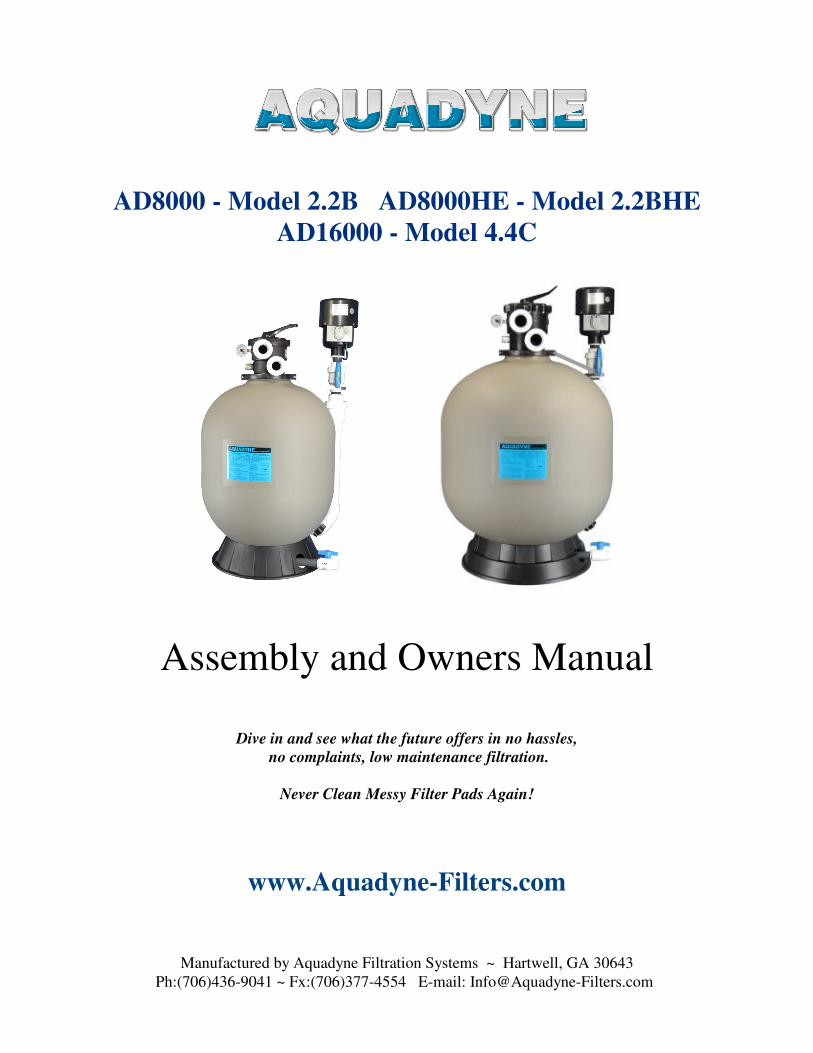
positioning is satisfactory. Refer to the Schematic Diagrams for a Visual Reference
Refer to the Schematic Diagrams for a Visual Reference
1. First unpack the main filter tank.
2. Remove any plumbing shipped inside the tank. (1) sludge drain valve, and (3) union fittings and elbows.
4. Screw the sludge drain into the fitting in the bottom of the tank, through the hole in the base. Teflon tape
has already been applied to the threads for you. Be sure the sludge valve is in the closed position.
5. Position the main filter body in a level location of your choosing. Most filters fit well on (6) 12 x 12
concrete pave stones from the local depot or hardware store if you do not have a prepared surface.
6. Glue the blower riser onto the 2” fitting protruding out of the lower right rear side of the of the filter make
sure to align the riser in the vertical position. Close the valve on the riser. (Hold 1 min. for glue to set)
7. Fill the main tank almost half full of water and pour in all of the beads included in your filter kit. The
water will float the beads enough for you to re-insert the head and column into the tank.
8. Lubricate the large O-ring that seals the control head to the tank with the included lubricant and re-insert
the control head and column into the tank and position the head to best suit your plumbing needs.
9. Reattach the neck clamp ring and tighten hand tight with a screwdriver. (Do Not Use Power Tools)
10. The drawing clearly indicates where you will attach the pump line, return line, and waste line. Be sure not
to over tighten the union couplings, for easy removal later.
11. Install the Air Blower on top of the blower riser and secure the blower support strap onto one of the
neck clamp bolts.
12. Once you have completed the main tank assembly, install your pump next to your filter according to the
diagram. Now you are ready to start your system. Read Operating Instructions Before Proceeding.
Manufactured by Aquadyne Filtration Systems ~ Hartwell, GA 30643
Ph:(706)436-9041 ~ Fx:(706)377-4554 E-mail: [email protected]
(F) Union Waste LineControl Handle
Main Control Head
(E) U
nio
n R
etu
rn L
ine
(D) Union Pump
and Air Blower Line
Main Filter Body
Dynamax
Aquadyne Model 2.2-B
with Dynamax Backwash
(D) Pump
(E) Return
(F) Waste
Schematic:
Drawing is for visual clarity
(D) actually installs behind (E)
Dynamax
Powerhead
Blower
Air Valve
Drawing is not to scale
and intended as a visual
reference guide only
Blower Bulkhead
Blower Suport
Strap
and 4.4-C
AquadyneBead Filter
Safety Spring
Check Valve
Main Blower Riser
2" Adapter

Backwashing your Aquadyne
1. Shut off the main pump. The main pump should NOT operate while the Dynamax blower is running.
2. Place the main control head in the Rinse position.
3. Open the Blower Valve under the blower, and switch on the blower.
4. At first about 2 to 4 gallons of water will discharge from the waste line, followed by bursts of air produced
by the washing action of the air escaping from the main tank during blower operation.
5. Allow the blower to run for at lease 3 minutes to effectively pre-clean the bead media.
6. Switch the blower off, and close the blower control valve.
7. Set the main control head to the backwash position.
8. Turn the main pump back on.
9. Once the discharge begins to run clear from the backwash cycle, turn the pump off and switch the control
head to the Rinse position. Turn the pump back on for at least 30 seconds to rinse the media.
10. Turn the pump off and return the control head back to the filter position, then turn the pump back on and
you are finished.
11. After backwashing, and once the control head is returned to the filter position, always open the sludge
valve located at the bottom of the filter for a few seconds to purge any heavy solids from the bottom of the tank.
Opening the sludge valve during the backwash cycle is NOT recommended.
You may loose bead media through the sludge valve during the backwash cycle.
Do NOT allow the handle to cross over the “closed” position while performing any control head position changes
while the pump is running. Damage may occur if the handle is accidentally allowed to snap into the closed
position while the pump is running..
Backwashing is recommended weekly. However you can go for extended periods of time if necessary.
It is hard to resist wanting to backwash your filter, especially for the first few times. However, it is important that fish
waste and other debris be allowed to accumulate in the filter media so that the beneficial biological bacteria can
established a healthy colony.
NOTE: If you do not have a large volume of air escaping the waste line when the Blower is running, or you can
not hear a violent stirring of the bead media when placing your ear against the tank, try rotating the main control
head back and forth between backwash and rinse 2 or 3 times with the main pump running, BEFORE switching
to the Blower mode. This will free any debris that is stuck on the waste line slots of the main column and allow
free passage of both air and waste.
Manufactured by Aquadyne Filtration Systems ~ Hartwell, GA 30643
Ph:(706)436-9041 ~ Fx:(706)377-4554 E-mail: [email protected]

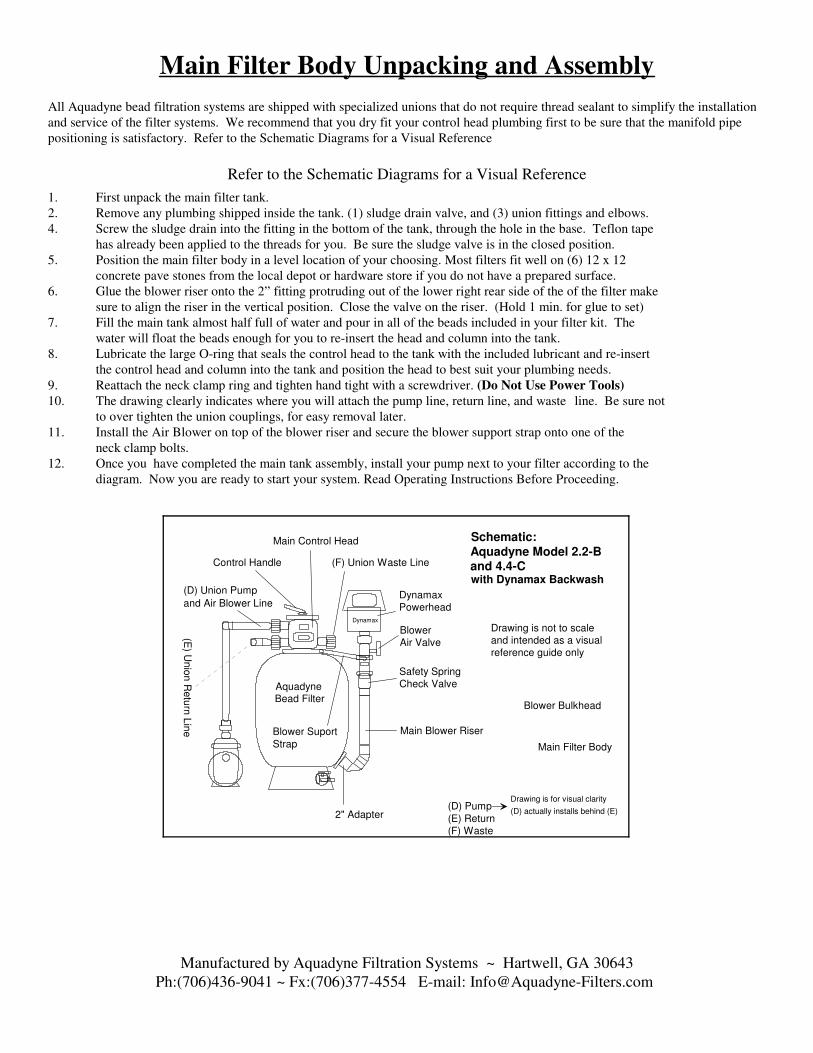
Aquadyne Control Head Functions:
The “Filter” position is used for the normal flow of water through the filter system.
The “Backwash” position is used to back flush waste and debris from the filter.
The “Rinse” position is used to pre-rinse the bead media prior to returning to the filter mode, which prevents the return
of any harmful debris back to the pond environment.
The “Rinse” position is also used to vent air from the Dynamax blower when it is in use.
The “Recirculate” position is used to bypass the normal flow of water away from the filter media while maintaining
pond circulation. This is beneficial when medicating the pond with agents that may be harmful to the beneficial bacterial
colonies which reside in the bead media.
The “Waste” position also bypasses the filter media. Water flows from the pump, through the control head and out to
waste. This position can be beneficial to diagnose any water flow problems, or to simply drain the pond. It can also be
used to discharge vacuum waste, if you attach a vacuum hose to your pump suction.
The “Closed” position stops all flow of water through the control head. This position has little use except in a case
where the filter is installed below the water level, it will function as a shutoff valve to prevent water back flowing
through the pump strainer basket if the lid is removed. If you change control head positions while the pump is
running, and the handle accidentally slips into the closed position, damage may result to your filter. While it is
acceptable to change the control handle position while the pump is running, always rotate the handle in a direction away
from the closed position.
The “Winter” position is a raised notch which opens all ports of the control head and allows water to drain from the
control head and column to prevent freezing and damage. The bottom sludge drain must also be slightly opened to allow
water to drain from the main tank body and internal column.
Manufactured by Aquadyne Filtration Systems ~ Hartwell, GA 30643
Ph:(706)436-9041 ~ Fx:(706)377-4554 E-mail: [email protected]
Filter
Backwash
Rin
seW
aste
Waste
Out
Pump
In
Return
to Pond
Clo
sed
Winter
Reci
rcula
te
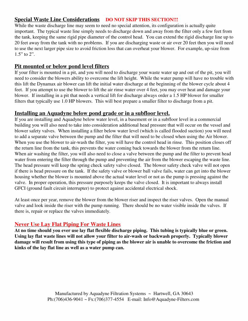
Special Waste Line Considerations DO NOT SKIP THIS SECTION!!!
While the waste discharge line may seem to need no special attention, its configuration is actually quite
important. The typical waste line simply needs to discharge down and away from the filter only a few feet from
the tank, keeping the same rigid pipe diameter of the control head. You can extend the rigid discharge line up to
20 feet away from the tank with no problems. If you are discharging waste or air over 20 feet then you will need
to use the next larger pipe size to avoid friction loss that can overheat your blower. For example, up-size from
1.5” to 2”.
Pit mounted or below pond level filtersIf your filter is mounted in a pit, and you will need to discharge your waste water up and out of the pit, you will
need to consider the blowers ability to overcome the lift height. While the water pump will have no trouble with
this lift the Dynamax air blower can lift the initial water discharge at the beginning of the blower cycle about 4
feet. If you attempt to use the blower to lift the air rinse water over 4 feet, you may over heat and damage your
blower. If installing in a pit that needs a vertical lift for discharge always order a 1.5 HP blower for smaller
filters that typically use 1.0 HP blowers. This will best prepare a smaller filter to discharge from a pit.
Installing an Aquadyne below pond grade or in a subfloor level.If you are installing and Aquadyne below water level, in a basement or in a subfloor level in a commercial
building you will also need to take into consideration additional head pressure that will occur on the vessel and
blower safety valves. When installing a filter below water level (which is called flooded suction) you will need
to add a separate valve between the pump and the filter that will need to be closed when using the Air blower.
When you use the blower to air-wash the filter, you will have the control head in rinse. This position closes off
the return line from the tank, this prevents the water coming back towards the blower from the return line.
When air washing the filter, you will also need to close a valve between the pump and the filter to prevent head
water from entering the filter through the pump and preventing the air from the blower escaping the waste line.
The head pressure will keep the spring check safety valve closed. The blower safety check valve will not open
if there is head pressure on the tank. If the safety valve or blower ball valve fails, water can get into the blower
housing whether the blower is mounted above the actual water level or not as the pump is pressing against the
valve. In proper operation, this pressure purposely keeps the valve closed. It is important to always install
GFCI (ground fault circuit interrupter) to protect against accidental electrical shock.
At least once per year, remove the blower from the blower riser and inspect the riser valves. Open the manual
valve and look inside the riser with the pump running. There should be no water visible inside the valves. If
there is, repair or replace the valves immediately.
Never Use Lay Flat Piping For Waste LinesAt no time should you ever use lay flat flexible discharge piping. This tubing is typically blue or green.
Using lay flat waste lines will not allow your filter to air-wash or backwash properly. Typically blower
damage will result from using this type of piping as the blower air is unable to overcome the friction and
kinks of the lay flat line as well as a water pump can.
Manufactured by Aquadyne Filtration Systems ~ Hartwell, GA 30643
Ph:(706)436-9041 ~ Fx:(706)377-4554 E-mail: [email protected]
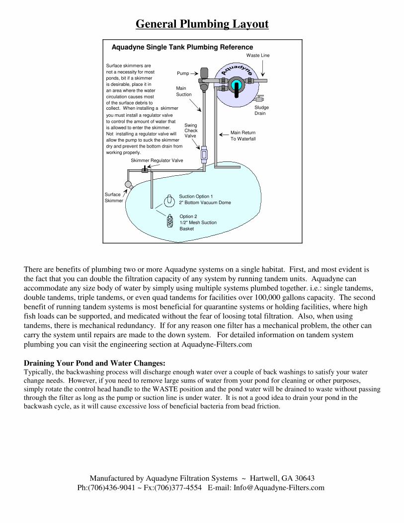
General Plumbing Layout
There are benefits of plumbing two or more Aquadyne systems on a single habitat. First, and most evident is
the fact that you can double the filtration capacity of any system by running tandem units. Aquadyne can
accommodate any size body of water by simply using multiple systems plumbed together. i.e.: single tandems,
double tandems, triple tandems, or even quad tandems for facilities over 100,000 gallons capacity. The second
benefit of running tandem systems is most beneficial for quarantine systems or holding facilities, where high
fish loads can be supported, and medicated without the fear of loosing total filtration. Also, when using
tandems, there is mechanical redundancy. If for any reason one filter has a mechanical problem, the other can
carry the system until repairs are made to the down system. For detailed information on tandem system
plumbing you can visit the engineering section at Aquadyne-Filters.com
Draining Your Pond and Water Changes:Typically, the backwashing process will discharge enough water over a couple of back washings to satisfy your water
change needs. However, if you need to remove large sums of water from your pond for cleaning or other purposes,
simply rotate the control head handle to the WASTE position and the pond water will be drained to waste without passing
through the filter as long as the pump or suction line is under water. It is not a good idea to drain your pond in the
backwash cycle, as it will cause excessive loss of beneficial bacteria from bead friction.
Manufactured by Aquadyne Filtration Systems ~ Hartwell, GA 30643
Ph:(706)436-9041 ~ Fx:(706)377-4554 E-mail: [email protected]
Main Return
To Waterfall
Suction Option 1
2" Bottom Vacuum Dome
Option 2
1/2" Mesh Suction
Basket
Pump
Main
Suction
Skimmer Regulator Valve
Surface
Skimmer
Aquadyne Single Tank Plumbing Reference
Surface skimmers are
not a necessity for most
ponds, bit if a skimmer
is desirable, place it in
an area where the water
circulation causes most
of the surface debris to collect. When installing a skimmer
you must install a regulator valve
to control the amount of water that
is allowed to enter the skimmer.
Not installing a regulator valve will
allow the pump to suck the skimmer
dry and prevent the bottom drain from
working properly.
Waste Line
Sludge
Drain
SwingCheckValve

Medicating Your Pond:At times it may be necessary to add medications to your pond that will harm the beneficial bacteria in your biological filter. In this
case you will simply position the top control handle to the RECIRCULATE. position. Always perform a BACKWASH cycle before
closing off your filter from circulation. This will clear the filter of waste and prevent it from becoming septic. Before returning the
filter to normal operation, backwash the filter again to discharge any septic water that may have formed in the filter while being
bypassed. RECIRCULATE. allows the water coming from the pump to bypass the filter completely and recirculate to the pond
without passing through the filter media, and thus not killing the biological capacity of your filter. The beneficial bacteria should be
able to survive in the closed system for many weeks. When you return your filter to normal operation after an extended period of
medicating, the capacity of the filter may be stunted for a short time, but should catch back up with the demand of your pond within a
couple of days. Always perform a 50% water change after medicating your pond.
Winterizing Your Filter:Many people find is necessary to shut their pumps off in the winter time. If this is the case you will need to winterize your pump and
filter system. First, perform a complete backwash cycle and shut your pump off. Next, drain the main tank by placing the main control
head in the “Winter” position and open the sludge drain and allow the water to trickle out. Do not open the sludge drain fully and
leave the filter unattended or the bead media will surely run out of the tank. However, it is acceptable to open the sludge drain fully to
accelerate the draining process if you are there to close the valve to a trickle at the first sight of beads escaping. You may remove the
winterizing cap if you wish. However, due to the sludge drain being post factory installed lower than the original winterize cap, the
cap no longer serves as a necessary component of the filter. Again, do not fully open the sludge drain valve to drain the tank water
unattended as the beads will wash out by the hundreds. Once the tank is drained leave the valve cracked just a little to prevent any
water from freezing in the pipe. Do not be alarmed if on occasion you loose a few beads from the sludge lower waste drain. This is
normal as on occasion some beads will be trapped in clumps of waste that will discharge through the drain. You could loose several
pounds of beads from most sizes before you ever affected the filters biological capacity. Replacement beads are available if you
should ever want to top off your filter, but be cautious not to add more than the specified weight for your filter, as the filter has been
designed to function properly with a specific quantity of beads.
VacationIf you plan to be away from your pond for an extended period of time, there is no need to worry about backwashing your filter while
you are away unless your pond is heavily stocked and requires more frequent cleaning. The filter is designed so that there is little
resistance to water flow through the media and diffuser column. If you are normally backwashing once per week and not getting an
extreme amount of dirt waste from the filter, you can leave you filter running for three to four weeks unattended, depending on the
filter size and fish load, but you will want to perform a very good backwash upon returning to assure that the filter is clean.
Filter Care and Maintenance
Rubber O-ring Lubrication may be necessary if the main control handle becomes difficult to reposition. Over the years the factory
lubrication may dry out on the two small orings located on the flow control stem which require lubrication. To perform this procedure,
first use a pin driver to remove the Steel Handle Pin from the Control Handle. (A pin driver can be any blunt steel rod which has a
smaller diameter than the rod itself, which can be driven through the control handle.) Next remove the Stainless Machine Screws or
bolts which hold down the Main Cap to the Control Head Body and remove the Main Cap assembly from the control head body.
Grasp the Main Cap in one hand and the Flow Control Hub in the other and twist while pulling them apart from each other. This will
expose the two rubber o-rings located on the Flow control Stem. Lubricate the two o-rings liberally with a silicone based or similar
o-ring lubricant. It is not necessary to remove the o-rings from the stem unless they are leaking or broken. If it is necessary to remove
the o-rings, remove the lower o-ring first, being careful not to scratch or gouge the inner surfaces of the o-ring seat with a sharp object.
Then remove the upper o-ring and split washer. When reinstalling the o-rings, replace the upper o-ring and split washer first and the
lower o-ring last. At this time, remove, clean, and lubricate the Main Cap O-ring before reassemble. Re-insert the Main Stem and Hub
assembly into the Main Cap and be sure that the Open Hub Port in the Main Hub is aligned with the Filter Position indicated in writing
on the Main Cap label. Insert the reassembled Main Cap assembly into the Control Head Body, being sure to align the Main Cap
Indexing Divot with the Main Cap Indexing Stud on the Control Head Body. Re-insert the Stainless Machine Screws or bolts into the
Main Cap and hand tighten in a cross over pattern as you would the lug nuts on an automotive wheel. This will assure a uniformly
seated Main Cap assembly. Place the Control Handle onto the Flow Control Stem with the Control Position Pointer facing the Filter
Position indicated in writing on the Main Cap label. If the Open Hub Port and the Control Position Pointer are not aligned in this
fashion the filter will not work properly when returned to service. Lastly, re-insert the Steel Handle Pin into the Control Handle and
drive it flush on both sides. If you ever experience a leak from between the main control head body and the filter tank it is
likely that the Main Control Head O-ring Gasket either needs lubricating or replacing.
Manufactured by Aquadyne Filtration Systems ~ Hartwell, GA 30643
Ph:(706)436-9041 ~ Fx:(706)377-4554 E-mail: [email protected]

Service Guide For 1.5” Control Head Multiport Valve
Please refer to these part names when ordering parts. If you ever have service issues with your control head, this
addendum will be very helpful in deciding on which o-rings that may need replacing. As with any product,
there are parts that will need to be replaced due to normal wear. Below you will find a complete diagram and
troubleshooting instructions for Aquadyne filter heads with standard 1.5” plumbing ports.
Manufactured by Aquadyne Filtration Systems ~ Hartwell, GA 30643
Ph:(706)436-9041 ~ Fx:(706)377-4554 E-mail: [email protected]
Steel Flat Washer
Rubber Oring
2 each
2 each
Plastic Split Washer
Main Cap Oring
Steel Handle Pin
Control Handle
Stainless Machine
Screw 6 each
Main Control Head
Oring Gasket
Waste Line Out
Pump Line In
Return Line Outto UV or Pond
Pressure Guage
Flow Control Hub and Stem
Main Hub Spring
Main Cap Indexing
Stud
Main Cap Indexing
Divot
Column Attachment Nuts
Column
Teflon Washer
Molded Permanent
Spider Gasket
Standard Main Control Head
1.5" Ports Heads
Spider Gasket Seat
Main Cap
Key Cover and Handle
Assembly includes allparts from the Control Handle to the Spider Gasket
Diverter
Port
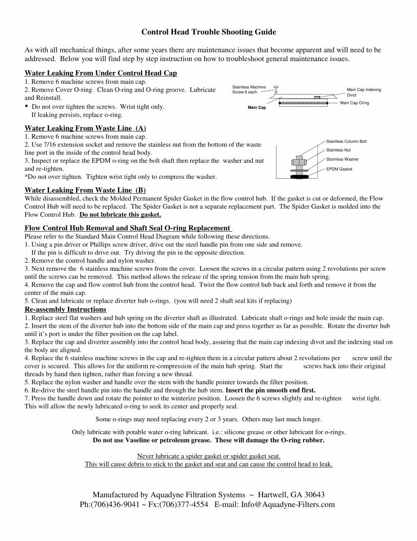
Control Head Trouble Shooting Guide
As with all mechanical things, after some years there are maintenance issues that become apparent and will need to be
addressed. Below you will find step by step instruction on how to troubleshoot general maintenance issues.
Water Leaking From Under Control Head Cap 1. Remove 6 machine screws from main cap.
2. Remove Cover O-ring. Clean O-ring and O-ring groove. Lubricate
and Reinstall.
� Do not over tighten the screws. Wrist tight only.
If leaking persists, replace o-ring.
Water Leaking From Waste Line (A)1. Remove 6 machine screws from main cap.
2. Use 7/16 extension socket and remove the stainless nut from the bottom of the waste
line port in the inside of the control head body.
3. Inspect or replace the EPDM o-ring on the bolt shaft then replace the washer and nut
and re-tighten.
*Do not over tighten. Tighten wrist tight only to compress the washer.
Water Leaking From Waste Line (B)While disassembled, check the Molded Permanent Spider Gasket in the flow control hub. If the gasket is cut or deformed, the Flow
Control Hub will need to be replaced. The Spider Gasket is not a separate replacement part. The Spider Gasket is molded into the
Flow Control Hub. Do not lubricate this gasket.
Flow Control Hub Removal and Shaft Seal O-ring Replacement Please refer to the Standard Main Control Head Diagram while following these directions.
1. Using a pin driver or Phillips screw driver, drive out the steel handle pin from one side and remove.
If the pin is difficult to drive out. Try driving the pin in the opposite direction.
2. Remove the control handle and nylon washer.
3. Next remove the 6 stainless machine screws from the cover. Loosen the screws in a circular pattern using 2 revolutions per screw
until the screws can be removed. This method allows the release of the spring tension from the main hub spring.
4. Remove the cap and flow control hub from the control head. Twist the flow control hub back and forth and remove it from the
center of the main cap.
5. Clean and lubricate or replace diverter hub o-rings. (you will need 2 shaft seal kits if replacing)
Re-assembly Instructions1. Replace steel flat washers and hub spring on the diverter shaft as illustrated. Lubricate shaft o-rings and hole inside the main cap.
2. Insert the stem of the diverter hub into the bottom side of the main cap and press together as far as possible. Rotate the diverter hub
until it’s port is under the filter position on the cap label.
3. Replace the cap and diverter assembly into the control head body, assuring that the main cap indexing divot and the indexing stud on
the body are aligned.
4. Replace the 6 stainless machine screws in the cap and re-tighten them in a circular pattern about 2 revolutions per screw until the
cover is secured. This allows for the uniform re-compression of the main hub spring. Start the screws back into their original
threads by hand then tighten, rather than forcing a new thread.
5. Replace the nylon washer and handle over the stem with the handle pointer towards the filter position.
6. Re-drive the steel handle pin into the handle and through the hub stem. Insert the pin smooth end first.
7. Press the handle down and rotate the pointer to the winterize position. Loosen the 6 screws slightly and re-tighten wrist tight.
This will allow the newly lubricated o-ring to seek its center and properly seal.
Some o-rings may need replacing every 2 or 3 years. Others may last much longer.
Only lubricate with potable water o-ring lubricant. i.e.: silicone grease or other lubricant for o-rings.
Do not use Vaseline or petroleum grease. These will damage the O-ring rubber.
Never lubricate a spider gasket or spider gasket seat.
This will cause debris to stick to the gasket and seat and can cause the control head to leak.
Manufactured by Aquadyne Filtration Systems ~ Hartwell, GA 30643
Ph:(706)436-9041 ~ Fx:(706)377-4554 E-mail: [email protected]
Main Cap Oring
Stainless Machine
Screw 6 eachMain Cap Indexing
Divot
Main Cap
Stainless Nut
Stainless Column Bolt
Stainless Washer
EPDM Gasket

Filter is loading too quickly between backwash cycles
Water slows down hours after a fresh backwash
Typically, the reason for these occurrences is that the media depth is too low. This can occur as a result of excessive
bead loss through the sludge valve, usually over a period of years. It is common to loose a few beads when opening the
sludge drain. This loss usually amounts to no more than 1 to 2 pounds of media per year. Over time this adds up and the
bead depth is reduced. The lower the bead media depth the less media there is to trap waste products therefore the media
loads faster. Bead loss can also occur due to improper backwashing. Opening the sludge valve only when the filter is in
filter position minimizes bead loss. In the filter position the media is floating and compacted towards the top of the filter
and away from the sludge valve. The following are instructions on how to gain access to the media and measure the bead
media depth. If you bead depth is sufficient the problem may be pump related.
Control Head and Column Removal
1. Turn off pump and attached equipment.
2. Detach all PVC lines from the control head. This is
typically done by unscrewing union connectors.
3. Using a #2 Phillips head screwdriver, remove the 2 screws on
either side of the neck clamp that attaches the black control
head to the beige tank and remove the neck clamp from the tank.
4. Lift straight up on the control head and the entire head and
column can be easily removed.
Note: When removing column from tank, always inspect it
thoroughly. Remove any beads that might have become trapped in
the upper slots. Typically, some media will become trapped in the
upper slots over time, which if significant can cause the flow rate
through the filter to decrease. The slots in both the upper and lower
sections are engineered to maintain a flow even when 75% blocked.
Measuring the Bead Media Depth
Remove the control head and column as directed above.
Fill the tank with water until the beads float 2 to 3 inches below the tank opening. Reach into the media and
feel for the bottom of the floating media. Insert a tape measure to your fingers and take the bead depth reading
from the surface of the media at the tank opening. It is not recommended to exceed the measurement capacity
by more than 10% when adding media to the tank.
Bead Capacity by Depth Measure
AD2000 / Model .60B --- 8.5 inches (3# of media per inch)
AD4000 / Model 1.1B --- 10.5 inches (4# of media per inch)
AD8000 / Model 2.2B --- 13.5 inches (6# of media per inch)
AD16000 / Model 4.4C - 15.5 inches (10# of media per inch)
AD30000 / Model 8.8C -- 16.5 inches (19# of media per inch)
Replacement Parts are available for all filter models factory direct by calling the phone numbers provided in the service
manuals or online at Aquadyne-Filters.com. It is our desire to make your Aquadyne experience as trouble free and
future cost effective as possible.
Manufactured by Aquadyne Filtration Systems ~ Hartwell, GA 30643
Ph:(706)436-9041 ~ Fx:(706)377-4554 E-mail: [email protected]
The Aquadyne Flow Control System is a Patented Product
That is Protected under United States Patent Law.
Aquadyne Head and Column Assembly
Aquadyne
Upper Slots
Return and Rinse
Lower SlotsInflux and Backwash
Main Column Body
Main Control Head
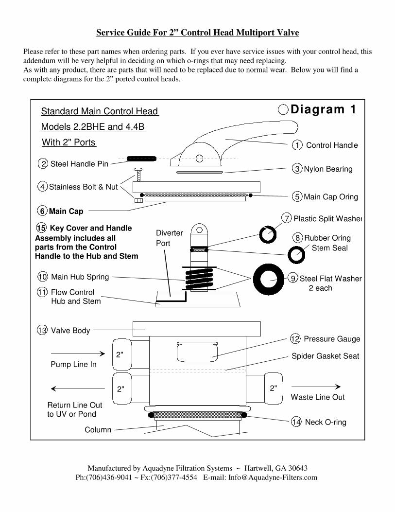
Service Guide For 2” Control Head Multiport Valve
Please refer to these part names when ordering parts. If you ever have service issues with your control head, this
addendum will be very helpful in deciding on which o-rings that may need replacing.
As with any product, there are parts that will need to be replaced due to normal wear. Below you will find a
complete diagrams for the 2” ported control heads.
Manufactured by Aquadyne Filtration Systems ~ Hartwell, GA 30643
Ph:(706)436-9041 ~ Fx:(706)377-4554 E-mail: [email protected]
9 Steel Flat Washer
8 Rubber Oring
2 each
Waste Line Out
Pump Line In
Return Line Outto UV or Pond
12 Pressure Gauge
Column
Standard Main Control Head
Models 2.2BHE and 4.4B
With 2" Ports
Spider Gasket Seat
15 Key Cover and Handle
Assembly includes allparts from the Control Handle to the Hub and Stem
Diverter
PortStem Seal
Diagram 1
1 Control Handle
2 Steel Handle Pin
2"
2" 2"
3 Nylon Bearing
4 Stainless Bolt & Nut
5 Main Cap Oring
6 Main Cap7 Plastic Split Washer
10 Main Hub Spring
11 Flow Control Hub and Stem
13 Valve Body
14 Neck O-ring

A-1 Water Leaking From Waste LineIf you have water leaking from the waste line of a 2” control head with the
pump running, a part of the spider gasket has come loose on one or both
sides of the waste port segment of the gasket. To repair, turn the pump off
and set the control head handle in the winter position. Then follow the
instructions below to effect the repair.
1. Use a screwdriver to remove the 10 stainless bolts from the control
head cover and pull up on the handle to remove the cover.
2. Inspect the segmented spider gasket that is glued inside the control
head that runs around all the segmented sections. If it is damaged it
must be replaced. Most waste line leaks occur in a 2” control head
because of a detachment of the gasket on either side of the waste line
port seal. To determine if the seal is detached using your thumb or
forefinger try to roll the gasket out of its track. If the gasket is
detached it will readily roll and snap back into place when released.
3. To repair this detachment, sponge out most of the water from the
interior of the control head. Roll the detached gasket to the side of its resting tray and dry underneath where the gasket normally
rests. This is easily done with a hair dryer set at low heat. Do not apply excessive heat as the gasket will swell with the heat and
not go back into its track. Using any super glue to glue the gasket back into its track with just enough glue to cover the bottom of
the track with a thin film and hold in place for a few minutes until it is set. Allow to air dry for at least 1 hour before re-assembly.
You can put the head back into service immediately after drying. Be careful not to glue yourself to the gasket. Do not lubricate
this gasket.
A-2 Water Leaking From Under Control Head Cap
1. Place the control handle in the Winter position.
2. Remove 10 bolts from main cap.
3. Remove Cover O-ring. Clean the O-ring and O-ring groove.
Lubricate and Reinstall.
� Do not over tighten the screws. Tighten wrist tight only. If leaking
persists, replace O-ring.
A-3 Flow Control Hub Removal and Shaft Seal O-ring Replacement Please refer to the Standard Main Control Head Diagram 1 while following these directions.
1. Using a pin driver or screw driver, drive out the steel handle pin from one side and remove the control handle and teflon washer.
2. Next remove the 10 stainless bolts from the cover. Loosen the screws in a circular pattern using 2 revolutions per screw until the
screws can be removed. This method allows the gradual release of the spring tension from the main hub spring.
3. Remove the cover and flow control hub from the control head. Twist the flow control hub back and forth and remove it from the
center of the main cover. This will expose the shaft seal o-ring and split washer on the flow control hub.
4. Clean and lubricate or replace diverter hub O-ring. Lubricate the O-ring and surrounding shaft as well as the hole in the cover
liberally with an O-ring lubricant or silicone grease. Do not use Vaseline on any rubber components or damage may result.
A-4 Flow Control Hub Re-assembly Instructions
1. Replace steel flat washers and hub spring on the diverter shaft as illustrated in Diagram 1.
2. Insert the stem of the diverter hub into the bottom side of the main cover and press together as far as possible. Rotate the diverter
hub until it’s port is under the filter position on the cap label. See Diagram 3 for re-assembly alignment of pointer and hub port.
3. Replace the cap and diverter assembly into the control head body, assuring that the flat indexing divot in the main cover and the
indexing flat on the body are aligned. (The indexing flat on the body is just off center of the pump input port.
4. Replace the 10 stainless machine screws in the cap and re-tighten them in a circular pattern about 2 revolutions per screw until the
cover is secured. This allows for the re-compression of the main hub spring.
5. Replace the teflon washer and handle over the stem with the handle pointer facing towards the filter position.
6. Re-drive the steel handle pin into the handle and through the hub stem. Hint: (Insert the pin smooth end first for easier driving.)
Some o-rings may need replacing every 2 or 3 years. Others may last much longer.
Only lubricate with potable water O-ring lubricant. ie: silicone grease or other lubricant for o-rings.
Do not use Vaseline or petroleum grease on any rubber O-ring components or damage may result.
Manufactured by Aquadyne Filtration Systems ~ Hartwell, GA 30643
Ph:(706)436-9041 ~ Fx:(706)377-4554 E-mail: [email protected]
Waste
Port
Top View
PumpPort
ReturnPort
Spider Gasket
Loose GasketMaterialIndexing Flat
2" Head
Diagram 2
G a u g e
Main Cover Oring
Stainless Bolt & Nut10 Each
Main Cover
D ive r t e r
P o r t
Reassembly Alignment
Diagram 3

Additional Important Information
� GFIC Breaker Always use a GFCI (Ground Fault Circuit Interrupter) breaker on your electrical pond equipment to avoid
the hazard of electrical shock. As with any electrical product, electricity can cause severe injury or even death.
� Sticky Or Hard To Move Control Handle This condition often arises from a drying of the lubricant inside the the
cover where the stem of the diverter hub passes through the cover, and also from ambient dirt and dust particles settling onto the
cover and washing into the stem area over many seasons of weather and rain. A quick fix is to spray some light general purpose
silicone lubricant into the area just around the handle and depress and rotate the handle while the silicone is still wet and flowing.
This will allow it to run down the stem and lubricate the hole under the handle where the stickiness is occurring. If this does not
resolve the issue, go to instruction A-4 on page 2 of this guide. It is advisable to inspect and lubricate the rubber O-rings in the
control head every 2 to 3 years to assure their condition and proper operation.
� Dynamax Blower Is Leaning Over On The Riser This condition is caused because the blower has gotten too hot
and has melted the housing and caused it to deform. There are 3 possible causes for this condition. As with any motor, air must
circulate through the motor to keep it cool. 1. If the ball valve under the blower is not open, air cannot circulate. Heat will build
up and the plastic housing will soften and deform. 2. If the water pump and the blower are run at the same time, the water pump
overpowers the blower and the safety check valve cannot open and the air cannot circulate, causing the same damage. 3. If the
waste line from the control head is obstructed, sufficient air cannot pass through the system to keep the blower cool, and damage
to the blower can result.
SPECIAL NOTE: Do not reduce the discharge diameter of the waste line to less than its original diameter. Doing so will
cause damage and the entire system will not operate efficiently. Reducing the diameter of the waste line can cause the
following: Overheating and damage to the blower. Poor air-wash and backwash performance. Premature filter loading,
requiring frequent backwash. Dirty water discharge into pond after backwash.
� Water Runs Out Of Blower Housing This condition results from a blockage of the blower riser safety check valve. In
order for this to occur, both the ball valve would have to be left open and the safety check valve would have to fail at the same
time. If this extremely rare event does occur, unplug and remove the blower power head. Remove the threaded reducer from the
bottom of the blower. Shake moisture out of housing. Also remove the switch cover and dry the switch mechanism if it got wet.
If you have an air compressor, blow a large volume of compressed air into the bottom of the blower. This should dry out the
windings of the blower enough to restart the unit. An equally effective method of drying is to place a shopvac hose over or into
the discharge of the blower and run the shopvac for about 15 minutes. This will move enough air through the blower to dry the
windings also. After one of these two procedures, reconnect the blower to an outlet and turn on the power switch. When the
blower starts, allow it to run for 15 minutes in the open air to completely dry out the inner parts of the blower. If the blower will
not restart or trips the breaker after the drying procedure, the blower will need to be replaced. Always use a GFCI (Ground Fault
Circuit Interrupter) breaker on your electrical pond equipment to avoid the hazard of electrical shock. As with any electrical
product, electricity can cause severe injury or even death. A wet blower must be dried as soon as possible for it to function again.
Typically, if a blower is left wet for more than a few hours, corrosion will cause irreparable damage of the electrical components
as well as bearings. Assure that the check valve on the blower riser is not leaking with the pump turned on and the ball valve open
before reinstalling the blower. To repair or clean the check valve or ball valve see the Blower Riser Diagram for disassembly and
re-assembly instructions.
Manufactured by Aquadyne Filtration Systems ~ Hartwell, GA 30643
Ph:(706)436-9041 ~ Fx:(706)377-4554 E-mail: [email protected]

Servicing the Blower Riser
Please refer to these part names when ordering parts. If you ever have service issues with your blower riser this
addendum will be very helpful in deciding which part may replacing. As with any product, there are parts that will need
to be replaced due to normal wear. Below you will find a complete diagram of the blower riser assembly and part names.
The riser shown in the diagrams is for Models 2.2B, 4.4C and 8.8C. Although the 1.1B and 8.8C configuration is
different with the check valve in the inside of the tank, the valve parts are identical.
Servicing The Blower Riser Components ( Visual Reference Diagram 4 )
Manufactured by Aquadyne Filtration Systems ~ Hartwell, GA 30643
Ph:(706)436-9041 ~ Fx:(706)377-4554 E-mail: [email protected]
Dynamax
Powerhead
Diagram 4
Ball Valve Union
Outer Union Gasket
Inner Union Gasket
Ball Seal Gasket (2)Ball
Ball Retainer
Assembly
Ball Retainer
Keeper Pins (2)
Handle
Keeper Pin
Pusher ToolRiser Support
Strap
Support Strap
Donut
Ball Valve Body
BallShaft
Outer Union Gasket
Inner Union Gasket
Valve Body Spring
Spring Seat
Valve Retainer
Assembly
Note: Model 1.1B and 8.8C spring
check valves are 1.5" and do not
have a spring seat.
1.5" Blower Riser Tank Bulkhead
Threaded BodyNut
Bulkhead Gasket
Custom
Male
AdapterSpring Valve Union
Check Valve
Gasket Assembly
Servicing the Blower Riser 1.5" Ball Valve Assembly
2" Spring Check Valve Assembly
Keeper Pin
Hole

� B-1 Ball Valve Trouble Shooting and Repair Praher valves are of the highest quality serviceable valves available.
These valves are used in the Aquadyne products to give the end user the ability to disassemble and repair the valves on-site
without delay so that equipment can be repaired and put back into service avoiding long periods of downtime.
1. Remove the ball valve union from the top of the ball valve.
2. Remove the keeper pin pusher tool from the back of the red handle.
3. Insert the tool into each keeper pin hole located in the threaded section of the valve body. Push the tool in far enough to
remove the keeper pins from the opposite side of the valve body. Remove both keeper pins and the tool.
4. With a thin flat blade screwdriver, gently pry out the ball retainer assembly. This will allow you to remove the ball and
interior pieces of the valve for service or repair.
5. Lubricate the valve O-rings and reassemble the valve. Be sure to re-insert the keeper pins before reattaching the union nut.
� B-2 Spring Check Valve Trouble Shooting and Repair
1. Remove the spring check union nut from the top of the spring check valve.
2. Insert two index fingers into the top of the valve retainer assembly, while simultaneously depressing the gasket assembly. Pull
upwards with your index fingers with force and the valve retainer assembly will slip out of the valve body.
3. Remove all internal parts and inspect the check valve gasket assembly to assure that it is not damaged and clear the inside of
the valve of any debris. These internal components rarely fail and thus usually never require replacing. If there is an
accumulation of bead media in the riser and valve body, it can easily be cleared by either pouring water into the valve body
allowing it to overflow. The floating media will wash out with the overflowing water. You can also insert a garden hose with
running water into the valve body and riser pipe. This will make short work of clearing the assembly.
4. Once clean, reassemble the components in the order removed and according to Diagram 4. Lubricate the O-rings with
silicone grease. Do not lubricate the check valve gasket assembly. Lubricant will cause the gasket to stick.
� B-3 Sludge Drain Assembly - Trouble Shooting and RepairIf the sludge drain becomes obstructed and water will not discharge when the valve is opened there is likely a sedimentation
blockage in the elbow or inside the tank itself just above the
bulkhead. This blockage can occur when the sludge drain is not
used on a regular basis and the sludge is not drained from the tank
with at least every other backwash. There are 3 ways to clear a
sludge drain blockage.
1. The easiest way to clear a sludge drain blockage is to acquire
a green flexible hedge branch and strip the leaves off. Open
the sludge valve and insert the branch into the drain pipe.
The green flexible branch can easily turn the corner at the
bulkhead and enter the tank, clearing debris as it is agitated.
2. If the drain cannot be cleared as above, another solution is to
connect a garden hose to the 1” ball valve. This will require
a female garden hose adapter that has a 1” male pipe thread
on the opposing end. This adapter can be made from 2
fittings easily available at any hardware store. This fitting
can be attached to the end of the ball valve and left
permanently if you wish. It will not impede the normal function of the sludge drain. Caution: You must set your control
head to the Backwash or Rinse position before turning on the water, otherwise damage may result. Most household
water pressures are between 60-80 psi. This is too much pressure for the filter tank. The Backwash or Rinse position
will vent all of the hose pressure to the waste line which will cause no harm at all.
3. The third and most assured way to free a sludge drain blockage is to remove the control head and column from the tank.
Reach inside to the bottom of the tank and check the inside of the bulkhead for the blockage. If you cannot reach the bottom
of the tank with your fingers on the larger models, use a stick or other dowel rod type device to probe for the bulkhead to
check the inside of the bulkhead for blockage. The typical blockage will be nothing more than sedimented dirt or debris that
has settled into the bulkhead opening. A bit of somewhat blind probing inside the bulkhead opening will disturb the debris
and allow it to wash out through the ball valve. There is nothing in the bottom of the tank that is likely to be damaged by
aggressive probing.
Manufactured by Aquadyne Filtration Systems ~ Hartwell, GA 30643
Ph:(706)436-9041 ~ Fx:(706)377-4554 E-mail: [email protected]
1" Sludge Drain Assembly
Bulkhead Assy.
1" Street L
1" Sch 80 Nipple
1" PVC Ball Valve
1" Sludge Drain Assembly
Bulkhead Assy.
1" Street L
1" Sch 80 Nipple
1" PVC Ball Valve1" Bulkhead
Gasket
Garden HoseAdapter
Reducer Bushing

Appendix
Symptom: When running a blower, the blower blows air back through the pump
and bubbles come out of the bottom drain or suction line in the pond.
Solution: The pathway to the pump remains open when the blower is running. If your pond is shallow the suction line
or bottom drain may not be deep enough to counteract the pressure of the blower as it airwashes the filter. This condition
needs to be resolved, because the air escaping from the pump needs to be used toward airwashing the filter. To resolve
this condition, simply install a swing check valve in the suction line, preferably as far away from the pump as possible.
Placing the valve farther away from the pump greatly assists in keeping the pump primed. However near the pump will
work as well.
Symptom: After a backwashing your filter, the water slows down more quickly than normal.
Solution: The first step is to wait until the condition occurs in full. Do not backwash the filter. Turn the pump off.
Remove the control head. Reach down through the center of the media and grab a fist full of media from the very bottom
of the floating media. If the media is a solid hard clumped mass, the filter is not airwashing properly. If the media is
dirty but not clumped, the media depth may be excessively low. Low media depth causes premature waste loading.
See “measuring the bead depth”.
If the media is only mildly dirty, check the pump for a clogged impeller or faulty wear ring.
Also inspect the slots in the central diffuser column. Remove any beads that are lodged in the slots and discard them.
The column is designed to operate normally even with many beads in the slots.
Symptom: There is a trickle of water coming out of the waste line when the filter control head is in
the filter position.
Solution: This situation has one of two causes. Either the spider gasket on the diverter hub is damaged or the Waste
Seal needs replacing. (Note: The Spider Gasket in a 2” ported control head is mounted inside the head and not on the
diverter hub.) See page 13 for parts layout and descriptions. Page 14 contains disassembly instructions.
Symptom: Water will not flow through the sludge drain.
Solution: If water will not flow through the sludge drain when opened, there is heavy sedimentation that has stopped up
the drain. It is necessary to open the sludge drain momentarily to evacuate sediment solids from the lower sedimentation
area of the filter every time that you backwash your filter system. If the sludge drain of your Aquadyne system is not
opened for extended periods of time, sediment waste products in the bottom of the filter can solidify and block the
passage of water through the drain. You should open the sludge drain at least 2 times per month, whether or not you
backwash your filter that often. Always open the sludge drain with the filter running in the filter position to drain solid
waste from the filter system. There are three ways to clear the drain.
#1. Open the stopped up drain and insert a small diameter flexible shaft with an upturned end (hedge branch) into the
drain pipe and force it past the elbow into the tank. If the obstruction is light, this should clear the drain easily.
#2. Acquire a hose fitting from the hardware store that will allow you to connect your garden hose to the 1” sludge drain
fitting. With the pump off, and the control head set to rinse, apply pressure to the garden hose from the house spigot.
The hose pressure should break the blockage loose.
#3. If the drain has not been opened in quite a while and you suspect a severe blockage then it is best to remove the
control head and column from the tank as described on page 14 and reach down to the bottom of the tank and feel for the
obstruction and physically remove it. If you cannot reach the bottom of the tank, or the sediment debris is very hard.
Then use a small diameter rod or even a screw driver or scraper type device and wiggle it into the lower elbow from
inside the tank with the sludge drain open. This will most definitely free the obstruction. If you still cannot get the drain
to clear then remove the media so that you can physically see the obstruction to clear it.
Manufactured by Aquadyne Filtration Systems ~ Hartwell, GA 30643
Ph:(706)436-9041 ~ Fx:(706)377-4554 E-mail: [email protected]

Symptom: You have a new installation, the filter has been running for two to four weeks and the
water quality has not visibly improved.
Solution: Initially a new pond will turn green before it is cycled and clears unless you have installed an ultraviolet
sterilizer when first setting up the pond. The average time for a pond to fully cycle is between 6 and 8 weeks and
possibly a little longer depending on biological conditions. This means that the naturally occurring nitrosamonas and
nitrobacter bacteria that support the decomposition of fish waste and waste nutrients not only have to live but thrive and
coat not only the bead media bed but also the solid surface area (the bottom) of the pond. New ponds tend to have a
higher pH especially where concrete is used inside the water volume. Rocks and concrete and even concrete blocks used
as plant stands can cause the pH to rise above 10 when a normal pH is 7.0. Concrete can cause the pH to remain high for
months if not remedied. It is very difficult to cycle bacteria in a high pH environment, and often times the water quality
will get much worse before it gets better. One remedy for high pH in a new pond with concrete is to add 1 Gallon of
Muriatic Acid per 2500 gallons of pond volume. This will leach the alkalinity out of the surface of the concrete and
lower the pH. Leave the pump running if there is concrete in a waterfall, and do not perform a water change for at least 5
to 7 days. After treatment test the pH. If it is still well above 7.0, then add an equal amount of Muriatic Acid for a
second treatment. Once the pH will hold between 7.0 and 8.0 the leaching will be sufficient to allow the cycling of
bacteria.
Perform at least a 50% water change and let your filter system run normally. You can add Ammonium Chloride (this is
like adding artificial fish waste) to the pond to help cycle the pond before adding any fish. Or you can add a small
amount of fish stock to start the cycling naturally. Muriatic Acid is very inexpensive at Depot stores, but be very careful
in handling any acid. Acid can cause extensive burns and blindness. When adding acid to the pond wear rubber gloves
and protective clothing and pour the acid very close to the surface at arms length to avoid splashing and do not breathe
the vapors. Read the cautionary label on the acid before use. Caution! Muriatic Acid will kill any fish in the pond, so
remove them before treatment. You may need to add an ultraviolet sterilizer to your system if you do not have one. No
filter will remove the green cellular algae from the water, however a properly cycled and balanced environment will
consume the nutrients necessary for green water algae to grow, thereby naturally eliminating it. Remember, a pond is a
living environment that naturally seeks to balance itself. If you have a little water circulating, a few plants, and a few
fish, the pond will balance itself eventually. The trick is not to do anything drastic like adding 20 fish to a brand new
environment with a swinging unbuffered pH and concrete in water and expect it to balance in 2 weeks and not loose half
the fish and at least devastatingly stress out the other half. So create and enjoy a balanced pond, for all its inhabitants.
Thank you for purchasing an Aquadyne Filtration System.
Sincerely,
Crane Enterprises
DBA: Aquadyne Filtration Systems
Ph: (706) 436-9041
Fx: (706) 377-4554
www.aquadyne-Filters.com
Manufactured by Aquadyne Filtration Systems ~ Hartwell, GA 30643
Ph:(706)436-9041 ~ Fx:(706)377-4554 E-mail: [email protected]