Embed Size (px)
Citation preview

Translation of Original Operating Manual
Assembly and Operating ManualCo-act EGP-CElectrical small components gripper forcollaborative operations

Imprint
2 13.00 | Co-act EGP-C | Assembly and Operating Manual | en | 389336
ImprintCopyright:This manual is protected by copyright. The author is SCHUNK GmbH & Co. KG. All rightsreserved.
Technical changes:We reserve the right to make alterations for the purpose of technical improvement.
Document number: 389336
Version: 13.00 | 29/07/2021 | en
Dear Customer,thank you for trusting our products and our family-owned company, the leadingtechnology supplier of robots and production machines.Our team is always available to answer any questions on this product and other solutions.Ask us questions and challenge us. We will find a solution!Best regards,Your SCHUNK team
Customer ManagementTel. +49-7133-103-2503Fax [email protected]
Please read the operating manual in full and keep it close to the product.

Table of Contents
Table of Contents1 General.................................................................................................................... 5
1.1 About this manual ................................................................................................ 51.1.1 Presentation of Warning Labels ............................................................... 51.1.2 Definition of Terms................................................................................... 61.1.3 Applicable documents .............................................................................. 61.1.4 Sizes .......................................................................................................... 61.1.5 Variants..................................................................................................... 6
1.2 Warranty .............................................................................................................. 71.3 Scope of delivery .................................................................................................. 71.4 Accessories ........................................................................................................... 7
2 Basic safety notes ................................................................................................... 82.1 Appropriate use.................................................................................................... 82.2 Not intended use.................................................................................................. 82.3 Product safety ...................................................................................................... 82.4 Obligations of the operator/integrator ............................................................... 92.5 Constructional changes ...................................................................................... 122.6 Gripper fingers ................................................................................................... 122.7 Environmental and operating conditions ........................................................... 132.8 Personnel qualification....................................................................................... 142.9 Personal protective equipment.......................................................................... 142.10 Notes on safe operation ..................................................................................... 152.11 Transport ............................................................................................................ 162.12 Malfunctions....................................................................................................... 162.13 Disposal .............................................................................................................. 162.14 Fundamental dangers......................................................................................... 17
2.14.1 Protection during handling and assembly .............................................. 172.14.2 Protection against dangerous movements............................................. 172.14.3 Protection against electric shock............................................................ 18
3 Technical data......................................................................................................... 193.1 Type key.............................................................................................................. 193.2 Connection data ................................................................................................. 213.3 Ambient conditions and operating conditions ................................................... 23
4 Design and description............................................................................................ 244.1 Design ................................................................................................................. 244.2 Description ......................................................................................................... 244.3 Display ................................................................................................................ 25
5 Assembly and settings ............................................................................................ 275.1 Installing and connecting.................................................................................... 275.2 Mechanical connection ...................................................................................... 27
313.00 | Co-act EGP-C | Assembly and Operating Manual | en | 389336
Table of Contents
5.2.1 Install gripper fingers.............................................................................. 325.3 Electrical connection .......................................................................................... 33
5.3.1 Connection assignment .......................................................................... 335.3.2 Actuation ................................................................................................ 43
5.4 Adjust gripping force .......................................................................................... 455.4.1 Size 25, 50, 64......................................................................................... 455.4.2 Size 40..................................................................................................... 46
5.5 Adjust the sensors .............................................................................................. 475.5.1 Size 25..................................................................................................... 475.5.2 Size 40, 50, 64......................................................................................... 48
6 Start-up .................................................................................................................. 49
7 Troubleshooting ..................................................................................................... 507.1 Product does not move ...................................................................................... 507.2 Product does not execute a complete stroke..................................................... 507.3 Product opens or closes jerkily........................................................................... 507.4 Gripping force too low........................................................................................ 507.5 Opening and closing times are not achieved...................................................... 517.6 Electric signals are not transmitted? ................................................................. 517.7 Faults which are displayed via LED Error ............................................................ 517.8 Acknowledge error ............................................................................................. 51
8 Maintenance .......................................................................................................... 52
9 EU-Declaration of Conformity ................................................................................. 53
10 Translation of original declaration of incorporation ................................................ 54
11 Annex to Declaration of Incorporation.................................................................... 55
12 Appendix ................................................................................................................ 5812.1 Commissioning checklist..................................................................................... 58
4 13.00 | Co-act EGP-C | Assembly and Operating Manual | en | 389336

General
1 General
1.1 About this manualThis manual contains important information for a safe andappropriate use of the product.This manual is an integral part of the product and must be keptaccessible for the personnel at all times.Before starting work, the personnel must have read andunderstood this operating manual. Prerequisite for safe working isthe observance of all safety instructions in this manual.Illustrations in this manual are provided for basic understandingand may differ from the actual product design.In addition to these instructions, the documents listed underApplicable documents [} 6] are applicable.
1.1.1 Presentation of Warning LabelsTo make risks clear, the following signal words and symbols areused for safety notes.
DANGERDanger for persons!Non-observance will inevitably cause irreversible injury or death.
WARNINGDangers for persons!Non-observance can lead to irreversible injury and even death.
CAUTIONDangers for persons!Non-observance can cause minor injuries.
CAUTIONMaterial damage!Information about avoiding material damage.
513.00 | Co-act EGP-C | Assembly and Operating Manual | en | 389336
General
6 13.00 | Co-act EGP-C | Assembly and Operating Manual | en | 389336
1.1.2 Definition of TermsThe term "product" replaces the product name on the title page inthis manual.
1.1.3 Applicable documents• General terms of business *• Catalog data sheet of the purchased product *• Variant-URID, UREK: Software Manual "SCHUNK Software module for URCap, Co-act EGP-C in UREK/URID variants" *• Variant-FCRXEK, FCRXID: Software Manual "SCHUNK software module for FANUC CRX, Co-act EGP-C in the variants FCRXEK / FCRXID" *• Variant-TMID, TMEK: Software Manual "SCHUNK software module for TMflow, Plug & Work Portfolio for Techman Robot" *• Variant M1013: Software Manual "SCHUNK software module for WCI (Work Cell Item), Plug & Work Portfolio for Doosan Robotics" *• DGUV certificate, certificate no. MF 18007*• Assembly and operating manuals of the accessories *The documents marked with an asterisk (*) can be downloaded on our homepage schunk.com
1.1.4 SizesThis operating manual applies to the following sizes:• Co-act EGP-C 25• Co-act EGP-C 40• Co-act EGP-C 50• Co-act EGP-C 64
1.1.5 VariantsThis operating manual applies to the following variations:• Co-act EGP-C KETI (KUKA iiwa, media flange inside, electrical)• Co-act EGP-C KTOE (KUKA iiwa, media flange touch, electrical)• Co-act EGP-C KMFE (KUKA iiwa, media flange, electrical)• Co-act EGP-C URID (Universal Robots, with feed-through)• Co-act EGP-C UREK (Universal Robots, external cabling)• Co-act EGP-C TMID (Techman Robot, with feed-through)• Co-act EGP-C TMEK (Techman Robot, external cabling)• Co-act EGP-C FCR7 (FANUC CR-7 iA, connection via EE interface)• Co-act EGP-C CR15 (FANUC CR-15iA, external cabling)• Co-act EGP-C FCRXID (FANUC CRX, with feed-through)• Co-act EGP-C FCRXEK (FANUC CRX, external cabling)
General
• Co-act EGP-C AUBO (AUBO Robotics i5, with feed-through)• Co-act EGP-C SCR35 (SIASUN SCR 3 and SCR 5, with feed-
through)• Co-act EGP-C HCR (Hanwha Collaborative Robots, with feed-
through)• Co-act EGP-C M1013 (DOOSAN Robot, with feed-through)• Co-act EGP-C ASSISTA (Mitsubishi Assista, external cabling)• Co-act EGP-C YHCP = (Yaskawa HC10 (PNP, with feed-through)• Co-act EGP-C YHCN = (Yaskawa HC10 (NPN, with feed-through)• Co-act EGP-C YDTP = (Yaskawa HC10DT (PNP, with feed-
through)• Co-act EGP-C YDTN = (Yaskawa HC10DT (NPN, with feed-
through)
1.2 WarrantyIf the product is used as intended, the warranty is valid for 24months from the ex-works delivery date under the followingconditions:• Observe the ambient conditions and operating conditions,
Ambient conditions and operating conditions [} 23]• Observe the specified maintenance intervals,
Maintenance [} 52]Parts touching the workpiece and wear parts are not included inthe warranty.
1.3 Scope of deliveryThe scope of delivery includes• Electrical small components gripper for collaborative operations
Co-act EGP-C in the version ordered• Assembly and Operating Manual• Accessory pack
1.4 AccessoriesThe following accessories, which are to be ordered separately, areavailable for the product:• Gripper fingersFor information regarding which accessory articles can be usedwith the corresponding product variants, see catalog data sheet.
713.00 | Co-act EGP-C | Assembly and Operating Manual | en | 389336
Basic safety notes
8 13.00 | Co-act EGP-C | Assembly and Operating Manual | en | 389336
2 Basic safety notes
2.1 Appropriate useThe product is designed exclusively for gripping and temporarilyholding workpieces or objects.• The product is intended for installation in a machine or as an
end effector of a robot, including for HRC (human-robotcollaboration) applications. The applicable guidelines must beobserved and complied with.
• The product may only be used within the scope of its technicaldata.
• The product is intended for industrial use.• Appropriate use of the product includes compliance with all
instructions in this manual.
2.2 Not intended useIt is not intended use if the product is used, for example, as apressing tool, stamping tool, lifting gear, guide for tools, cuttingtool, clamping device or a drilling tool.• Any utilization that exceeds or differs from the appropriate use
is regarded as misuse.
2.3 Product safetyThe product represents the state of the art and the recognizedsafety rules. However, the product can pose hazards if, forexample:• the product is not used as intended,• the product is not installed or maintained properly,• the safety and installation instructions are not observed,• the safety application conditions (SAC) are not observed, or
safety regulations of the equal value are not taken into account,see chapter Obligations of the operator/integrator [} 10] or
• the power supply fails or is changed.
Notes on power supply failureWhen power is lost, the gripper fingers of the product can movefreely, and their ability to maintain a hold on the load is notguaranteed. Therefore, the integrator or operator must ensurethat releasing the load can not pose any hazard.• Avoid any manner of working that may interfere with the
function and operational safety of the product.

Basic safety notes
2.4 Obligations of the operator/integratorThe operator / integrator must ensure that:• the product is only used as intended,• the product is only operated in an impeccable, functional
condition and is regularly inspected to make sure it is workingproperly,
• the operating manual is always available in a legible conditionand in its entirety at the machine's application location
• only sufficiently qualified and authorized personnel operate andmaintain the product,
• this personnel is regularly trained in all relevant questionsrelating to operational safety and environmental protection,and is familiar with the operating manual, particularly the safetyinformation contained therein.
In particular, the operator / integrator must ensure that thefollowing requirements and instructions for safe operation with arobot are met.
NOTESafety is only guaranteed if the following safety applicationconditions (SAC) are met. Alternatively, the integrator/operator can implement their ownrisk-reducing measures and evaluate them as part of their riskanalysis. Implementation of a risk analysis is vital in any event.
The following SACs are divided into general SAC-Gs and product-specific SAC-Ps.• SAC-Gs refer to the interface of the product to or on the overall
system. Since the configuration of the overall SCHUNK system isnot known, these SAC-Gs are usually provided as arecommendation. SAC-Gs that are not indicated below as a recommendation,must be followed or replaced by equivalent risk-mitigatingmeasures.
• SAC-Ps refer to the product Co-act EGP-C and must be compliedwith or replaced by equivalent risk-mitigating measures.
913.00 | Co-act EGP-C | Assembly and Operating Manual | en | 389336
Basic safety notes
10 13.00 | Co-act EGP-C | Assembly and Operating Manual | en | 389336
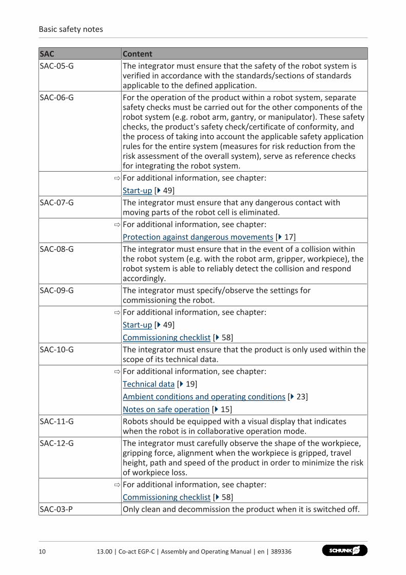
SAC ContentSAC-05-G The integrator must ensure that the safety of the robot system is
verified in accordance with the standards/sections of standardsapplicable to the defined application.
SAC-06-G For the operation of the product within a robot system, separatesafety checks must be carried out for the other components of therobot system (e.g. robot arm, gantry, or manipulator). These safetychecks, the product's safety check/certificate of conformity, andthe process of taking into account the applicable safety applicationrules for the entire system (measures for risk reduction from therisk assessment of the overall system), serve as reference checksfor integrating the robot system.⇨ For additional information, see chapter:
Start-up [} 49]SAC-07-G The integrator must ensure that any dangerous contact with
moving parts of the robot cell is eliminated.⇨ For additional information, see chapter:
Protection against dangerous movements [} 17]SAC-08-G The integrator must ensure that in the event of a collision within
the robot system (e.g. with the robot arm, gripper, workpiece), therobot system is able to reliably detect the collision and respondaccordingly.
SAC-09-G The integrator must specify/observe the settings forcommissioning the robot.⇨ For additional information, see chapter:
Start-up [} 49]Commissioning checklist [} 58]
SAC-10-G The integrator must ensure that the product is only used within thescope of its technical data.⇨ For additional information, see chapter:
Technical data [} 19]Ambient conditions and operating conditions [} 23]Notes on safe operation [} 15]
SAC-11-G Robots should be equipped with a visual display that indicateswhen the robot is in collaborative operation mode.
SAC-12-G The integrator must carefully observe the shape of the workpiece,gripping force, alignment when the workpiece is gripped, travelheight, path and speed of the product in order to minimize the riskof workpiece loss.⇨ For additional information, see chapter:
Commissioning checklist [} 58]SAC-03-P Only clean and decommission the product when it is switched off.
Basic safety notes
SAC Content⇨ For additional information, see chapter:
Fundamental dangers [} 17]SAC-04-P As part of the risk analysis of the overall system, a maximum
permissible workpiece weight must be determined for theapplication. Important factors here are workpiece parameters suchas shape and weight, as well as application parameters, such astravel height and speed. This maximum approved workpieceweight must not be exceeded.⇨ For additional information, see chapter:
Technical data [} 19]SAC-05-P Any accidental, unnecessary or unintentional activation of the
product must be prevented.⇨ For additional information, see chapter:
Protection during handling and assembly [} 17]Protection against dangerous movements [} 17]
SAC-06-P To ensure inherent safety levels, it is necessary to take into accountthe structural design of the fingers:• If possible, the gripper fingers should be designed so that
unintentional engagement with the gripper fingers is notpossible.
• The gripper fingers may not have sharp edges or rough surfacesthat could pose a hazard.
• The relevant requirements (e.g. BG Recommendations, ISO/TS15066, etc.) must be observed. Compliance with bio-mechanicallimits must be verified.
• If this is not possible, the integrator / operator must undertakefurther risk mitigation measures.
⇨ For additional information, see chapter:Gripper fingers [} 12]Commissioning checklist [} 58]
SAC-07-P The design of the gripper fingers must allow positive gripping tominimize the risk of loss of the workpiece in a de-energized state. Ifthis is not possible, the integrator / operator must undertakefurther risk mitigation measures.⇨ For additional information, see chapter:
Gripper fingers [} 12]SAC-08-P The integrator must bear in mind that a drop in the supply voltage
could lead to workpiece loss.⇨ For additional information, see chapter:
Technical data [} 19]
1113.00 | Co-act EGP-C | Assembly and Operating Manual | en | 389336
Basic safety notes
12 13.00 | Co-act EGP-C | Assembly and Operating Manual | en | 389336
SAC ContentSAC-09-P This product is not designed for handling hot or cold workpieces.
When handling hot or cold workpieces, heat transfer to theproduct must be prevented, which may result in the ambienttemperature falling below or exceeding the permissible contacttemperature. You can find further information in ISO 13732-1/-3.⇨ For additional information, see chapter:
Technical data [} 19]SAC-10-P The product may become damaged if in contact with acidic or
alkaline substances.⇨ For additional information, see chapter:
Ambient conditions and operating conditions [} 23]SAC-11-P The integrator must ensure that the product is grounded. For this
purpose, the mechanical connection must be made electricallyconductive.⇨ For additional information, see chapter:
Mechanical connection [} 27]Protection against electric shock [} 18]
SAC-12-P The product is equipped with a safety fuse as a safety component,which may not be replaced under any circumstances. Sendproducts to SCHUNK for repair.
2.5 Constructional changesImplementation of structural changesVia modifications, changes and reworking, e.g. additional threads,holes, or safety devices can impair the functioning or safety of theproduct or damage it.• Structural changes should only be made with the written
approval of SCHUNK.• Only use the product with the collision protection cover
installed by SCHUNK.
2.6 Gripper fingersRequirements of gripper fingersAccumulated energy can make the product unsafe and risk thedanger of serious injuries and considerable material damage.• Execute the gripper fingers in such a way that the product
reaches either the "open" or "closed" position in a de-energizedstate.
• Only change gripper fingers if no residual energy can bereleased.
• Make sure that the product and the top jaws are a sufficientsize for the application.
Basic safety notes
• When operating the robotic system without a protective fence,the gripper fingers must be designed so that bio-mechanicallimits are not exceeded, e. g. upon contact between gripperfingers and persons or the workplace.Compliance with bio-mechanical limits must be verified by theintegrator.
• Design the radii and surfaces of the gripper fingers so that theycomply with the requirements of collaborative workstations(e. g. BG/BGIA recommendations for risk assessment inaccordance with the Machine Directive "Designing workstationswith collaborating robots").
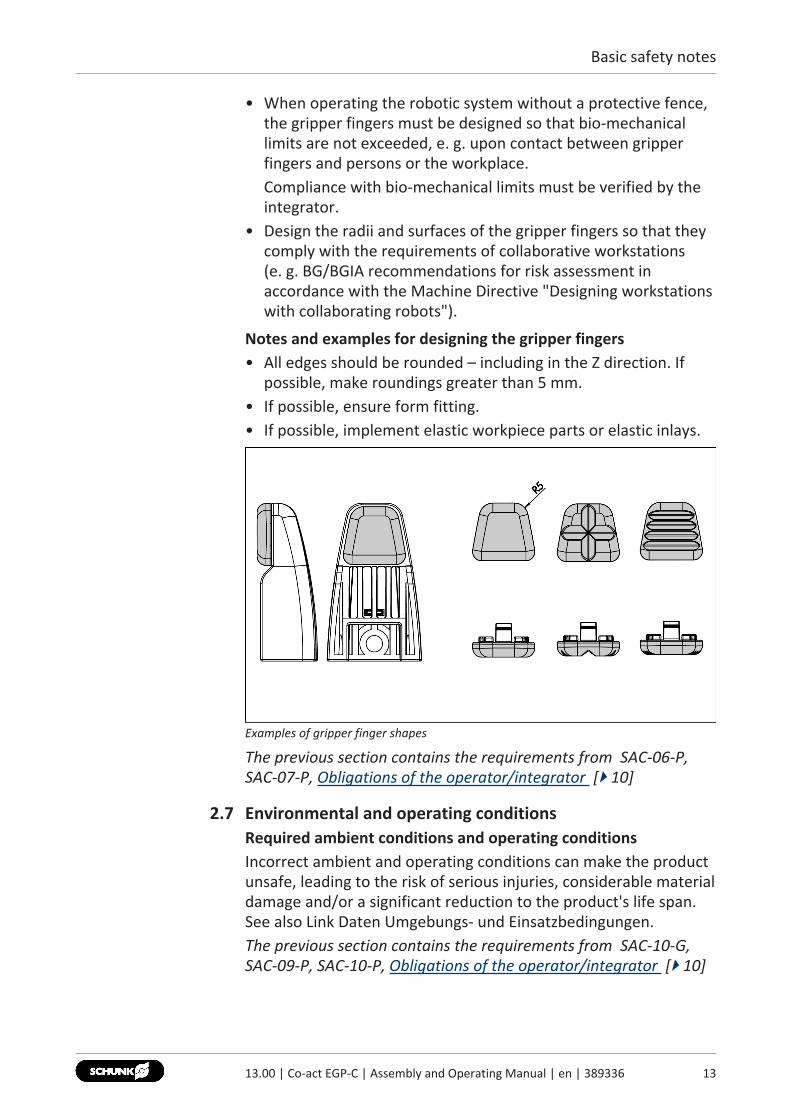
Notes and examples for designing the gripper fingers• All edges should be rounded – including in the Z direction. If
possible, make roundings greater than 5 mm.• If possible, ensure form fitting.• If possible, implement elastic workpiece parts or elastic inlays.
Examples of gripper finger shapes
The previous section contains the requirements from SAC-06-P,SAC-07-P, Obligations of the operator/integrator [} 10]
2.7 Environmental and operating conditionsRequired ambient conditions and operating conditionsIncorrect ambient and operating conditions can make the productunsafe, leading to the risk of serious injuries, considerable materialdamage and/or a significant reduction to the product's life span.See also Link Daten Umgebungs- und Einsatzbedingungen.The previous section contains the requirements from SAC-10-G,SAC-09-P, SAC-10-P, Obligations of the operator/integrator [} 10]
1313.00 | Co-act EGP-C | Assembly and Operating Manual | en | 389336

Basic safety notes
14 13.00 | Co-act EGP-C | Assembly and Operating Manual | en | 389336
2.8 Personnel qualificationInadequate qualifications of the personnelIf the personnel working with the product is not sufficientlyqualified, the result may be serious injuries and significantproperty damage.• All work may only be performed by qualified personnel.• Before working with the product, the personnel must have read
and understood the complete assembly and operating manual.• Observe the national safety regulations and rules and general
safety instructions.
The following personal qualifications are necessary for the variousactivities related to the product:
Trained electrician Due to their technical training, knowledge and experience, trainedelectricians are able to work on electrical systems, recognize andavoid possible dangers and know the relevant standards andregulations.
Qualified personnel Due to its technical training, knowledge and experience, qualifiedpersonnel is able to perform the delegated tasks, recognize andavoid possible dangers and knows the relevant standards andregulations.
Instructed person Instructed persons were instructed by the operator about thedelegated tasks and possible dangers due to improper behaviour.
Service personnel ofthe manufacturer
Due to its technical training, knowledge and experience, servicepersonnel of the manufacturer is able to perform the delegatedtasks and to recognize and avoid possible dangers.
2.9 Personal protective equipmentUse of personal protective equipmentPersonal protective equipment serves to protect staff againstdanger which may interfere with their health or safety at work.• When working on and with the product, observe the
occupational health and safety regulations and wear therequired personal protective equipment.
• Observe the valid safety and accident prevention regulations.• Wear protective gloves to guard against sharp edges and
corners or rough surfaces.• Wear heat-resistant protective gloves when handling hot
surfaces.• Wear protective gloves and safety goggles when handling
hazardous substances.• Wear close-fitting protective clothing and also wear long hair in
a hairnet when dealing with moving components.
Basic safety notes
2.10 Notes on safe operationIncorrect handling of the personnelIncorrect handling and assembly may impair the product's safetyand cause serious injuries and considerable material damage.• Avoid any manner of working that may interfere with the
function and operational safety of the product.• Use the product as intended.• Observe the safety notes and assembly instructions.• Do not expose the product to any corrosive media. This does
not apply to products that are designed for specialenvironments.
• Eliminate any malfunction immediately.• Observe the care and maintenance instructions.• Observe the current safety, accident prevention and
environmental protection regulations regarding the product'sapplication field.
What to do in an emergency• In the event of an emergency, disconnect the product from the
power supply and manually move the gripper fingers to the"gripper open" position.
The previous section contains the requirements from SAC-10-G,Obligations of the operator/integrator [} 10]
1513.00 | Co-act EGP-C | Assembly and Operating Manual | en | 389336
Basic safety notes
16 13.00 | Co-act EGP-C | Assembly and Operating Manual | en | 389336
2.11 TransportHandling during transportIncorrect handling during transport can make the product unsafeand risk the danger of serious injuries and considerable materialdamage.• During transport and handling, secure the product to prevent it
from falling.• Do not walk under suspended loads.
2.12 MalfunctionsBehavior in case of malfunctions• Immediately remove the product from operation and report the
malfunction to the responsible departments/persons.• Order appropriately trained personnel to rectify the
malfunction.• Do not recommission the product until the malfunction has
been rectified.• Test the product after a malfunction to establish whether it still
functions properly and no increased risks have arisen.What to do in an emergency• In the event of an emergency, disconnect the product from the
power supply and manually move the gripper fingers to the"gripper open" position.
2.13 DisposalHandling of disposalThe incorrect handling of disposal may impair the product's safetyand cause serious injuries as well as considerable material andenvironmental harm.• Follow local regulations on dispatching product components for
recycling or proper disposal.
Basic safety notes
2.14 Fundamental dangersGeneral• Observe safety distances where they were defined in the risk
assessment by the integrator / operator.• Never deactivate safety devices.• Disconnect power sources before installation, modification or
calibration. Ensure that no residual energy remains in thesystem.
• Do not reach into the movement area of the product duringoperation.
The previous section contains the requirements from SAC-03-P,Obligations of the operator/integrator [} 10]
2.14.1 Protection during handling and assemblyIncorrect handling and assemblyIncorrect handling and assembly may impair the product's safetyand cause serious injuries and considerable material damage.• Have all work carried out by appropriately qualified personnel.• For all work, secure the product against accidental operation.• Observe the relevant accident prevention rules.• Use suitable assembly and transport equipment and take
precautions to prevent jamming and crushing.Incorrect lifting of loadsFalling loads can cause serious injuries and even death.• Do not step under or within the swivel range of suspended
loads, as determined by the integrator / operator as part of therisk analysis.
• Never move loads without supervision.• Do not leave suspended loads unattended.The previous section contains the requirements from SAC-05-P,Obligations of the operator/integrator [} 10]
2.14.2 Protection against dangerous movementsUnexpected movementsResidual energy in the system may cause serious injuries whileworking with the product.• EMERGENCY STOP switches must be easily and quickly
accessible. Before commissioning the machine or automatedsystem, check that the EMERGENCY STOP system is working.Prevent operation of the machine if this protective equipmentdoes not function correctly.
The previous section contains the requirements from SAC-07-G,SAC-05-P, Obligations of the operator/integrator [} 10]
1713.00 | Co-act EGP-C | Assembly and Operating Manual | en | 389336
Basic safety notes
18 13.00 | Co-act EGP-C | Assembly and Operating Manual | en | 389336
2.14.3 Protection against electric shockWork on electrical equipmentTouching live parts may result in death.• Work on the electrical equipment may only be carried out by
qualified electricians in accordance with the electricalengineering regulations.
• Lay electrical cables properly, e. g. in a cable duct or a cablebridge. Observe standards.
• Before connecting or disconnecting electrical cables, switch offthe power supply and check that the cables are free of voltage.Secure the power supply against being switched on again.
• Before switching on the product, check that the protectiveearth conductor is correctly attached to all electricalcomponents according to the wiring diagram.
• Check whether covers and protective devices are fitted toprevent contact with live components.
• Do not touch the product's terminals when the power supply isswitched on.
The previous section contains the requirements from SAC-11-P,Obligations of the operator/integrator [} 10]Possible electrostatic energyComponents or assembly groups may become electrostaticallycharged. When the electrostatic charge is touched, the dischargemay trigger a shock reaction leading to injuries.• The operator must ensure that all components and assembly
groups are included in the local potential equalisation inaccordance with the applicable regulations.
• While paying attention to the actual conditions of the workingenvironment, the potential equalisation must be implementedby a specialist electrician according to the applicableregulations.
• The effectiveness of the potential equalisation must be verifiedby executing regular safety measurements.
Technical data
3 Technical data
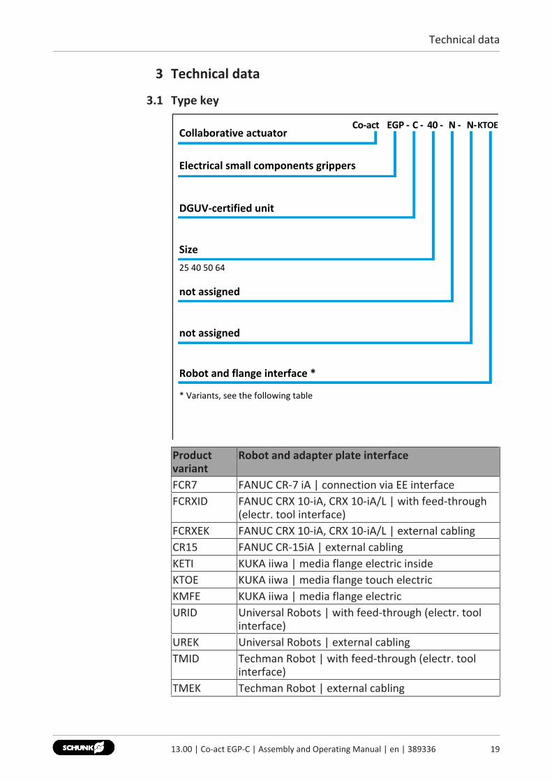
3.1 Type key
Co-act EGP - 40 - N - N-KTOECollaborative actuator
25 40 50 64
Electrical small components grippers
DGUV-certified unit
Size
not assigned
not assigned
C -
Robot and flange interface *
* Variants, see the following table
Productvariant
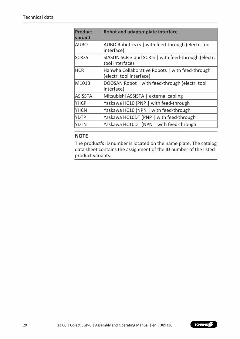
Robot and adapter plate interface
FCR7 FANUC CR-7 iA | connection via EE interfaceFCRXID FANUC CRX 10-iA, CRX 10-iA/L | with feed-through
(electr. tool interface)FCRXEK FANUC CRX 10-iA, CRX 10-iA/L | external cablingCR15 FANUC CR-15iA | external cablingKETI KUKA iiwa | media flange electric insideKTOE KUKA iiwa | media flange touch electricKMFE KUKA iiwa | media flange electricURID Universal Robots | with feed-through (electr. tool
interface)UREK Universal Robots | external cablingTMID Techman Robot | with feed-through (electr. tool
interface)TMEK Techman Robot | external cabling
1913.00 | Co-act EGP-C | Assembly and Operating Manual | en | 389336
Technical data
20 13.00 | Co-act EGP-C | Assembly and Operating Manual | en | 389336
Productvariant
Robot and adapter plate interface
AUBO AUBO Robotics i5 | with feed-through (electr. toolinterface)
SCR35 SIASUN SCR 3 and SCR 5 | with feed-through (electr.tool interface)
HCR Hanwha Collaborative Robots | with feed-through(electr. tool interface)
M1013 DOOSAN Robot | with feed-through (electr. toolinterface)
ASISSTA Mitsubishi ASSISTA | external cablingYHCP Yaskawa HC10 (PNP | with feed-throughYHCN Yaskawa HC10 (NPN | with feed-throughYDTP Yaskawa HC10DT (PNP | with feed-throughYDTN Yaskawa HC10DT (NPN | with feed-through
NOTEThe product's ID number is located on the name plate. The catalogdata sheet contains the assignment of the ID number of the listedproduct variants.
Technical data
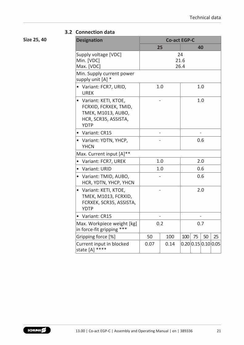
3.2 Connection dataSize 25, 40 Designation Co-act EGP-C
25 40Supply voltage [VDC]Min. [VDC]Max. [VDC]
2421.626.4
Min. Supply current power supply unit [A] *• Variant: FCR7, URID,
UREK1.0 1.0
• Variant: KETI, KTOE,FCRXID, FCRXEK, TMID,TMEK, M1013, AUBO,HCR, SCR35, ASSISTA,YDTP
- 1.0
• Variant: CR15 - -• Variant: YDTN, YHCP,
YHCN- 0.6
Max. Current input [A]**• Variant: FCR7, UREK 1.0 2.0• Variant: URID 1.0 0.6• Variant: TMID, AUBO,
HCR, YDTN, YHCP, YHCN- 0.6
• Variant: KETI, KTOE,TMEK, M1013, FCRXID,FCRXEK, SCR35, ASSISTA,YDTP
- 2.0
• Variant: CR15 - -Max. Workpiece weight [kg]in force-fit gripping ***
0.2 0.7
Gripping force [%] 50 100 100 75 50 25Current input in blockedstate [A] ****
0.07 0.14 0.20 0.15 0.10 0.05
2113.00 | Co-act EGP-C | Assembly and Operating Manual | en | 389336
Technical data
22 13.00 | Co-act EGP-C | Assembly and Operating Manual | en | 389336
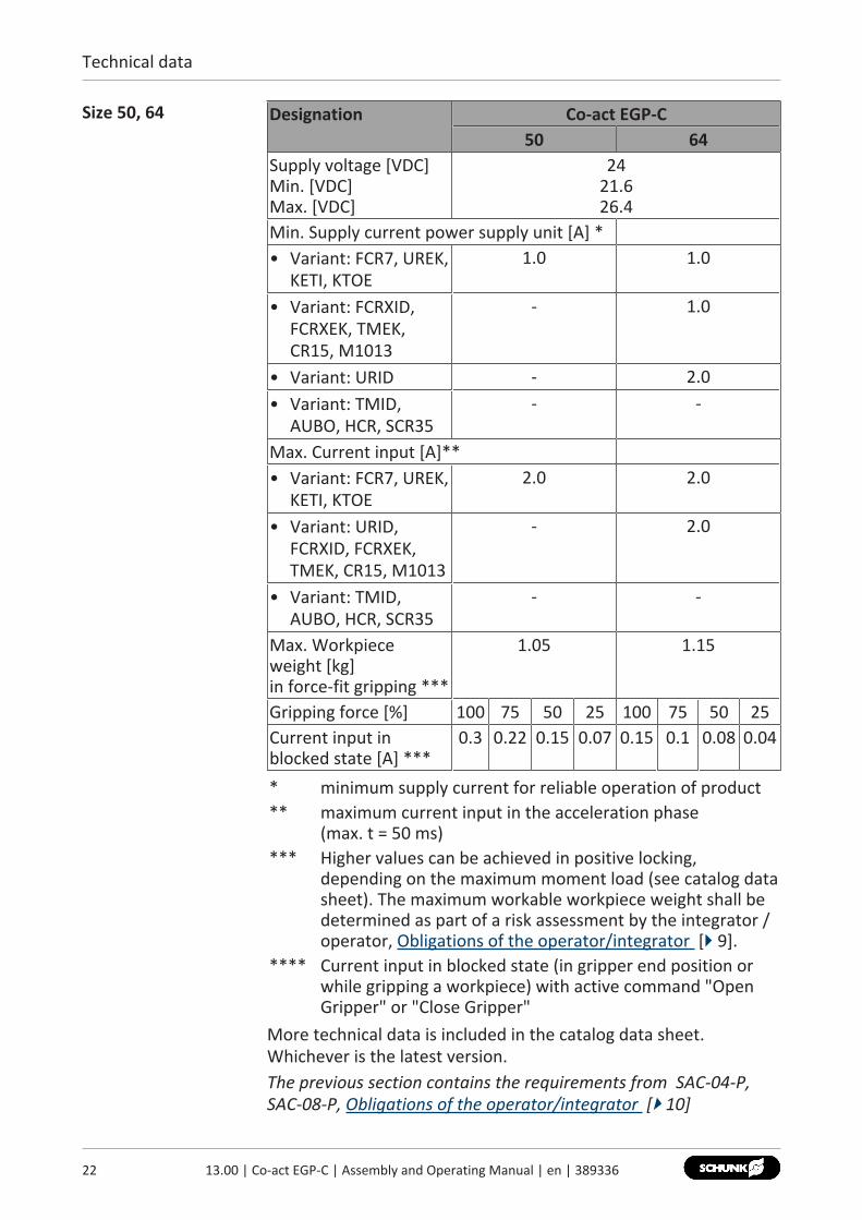
Size 50, 64 Designation Co-act EGP-C50 64
Supply voltage [VDC]Min. [VDC]Max. [VDC]
2421.626.4
Min. Supply current power supply unit [A] *• Variant: FCR7, UREK,
KETI, KTOE1.0 1.0
• Variant: FCRXID,FCRXEK, TMEK,CR15, M1013
- 1.0
• Variant: URID - 2.0• Variant: TMID,
AUBO, HCR, SCR35- -
Max. Current input [A]**• Variant: FCR7, UREK,
KETI, KTOE2.0 2.0
• Variant: URID,FCRXID, FCRXEK,TMEK, CR15, M1013
- 2.0
• Variant: TMID,AUBO, HCR, SCR35
- -
Max. Workpieceweight [kg]in force-fit gripping ***
1.05 1.15
Gripping force [%] 100 75 50 25 100 75 50 25Current input inblocked state [A] ***
0.3 0.22 0.15 0.07 0.15 0.1 0.08 0.04
* minimum supply current for reliable operation of product** maximum current input in the acceleration phase
(max. t = 50 ms)*** Higher values can be achieved in positive locking,
depending on the maximum moment load (see catalog datasheet). The maximum workable workpiece weight shall bedetermined as part of a risk assessment by the integrator /operator, Obligations of the operator/integrator [} 9].
**** Current input in blocked state (in gripper end position orwhile gripping a workpiece) with active command "OpenGripper" or "Close Gripper"
More technical data is included in the catalog data sheet.Whichever is the latest version.The previous section contains the requirements from SAC-04-P,SAC-08-P, Obligations of the operator/integrator [} 10]
Technical data
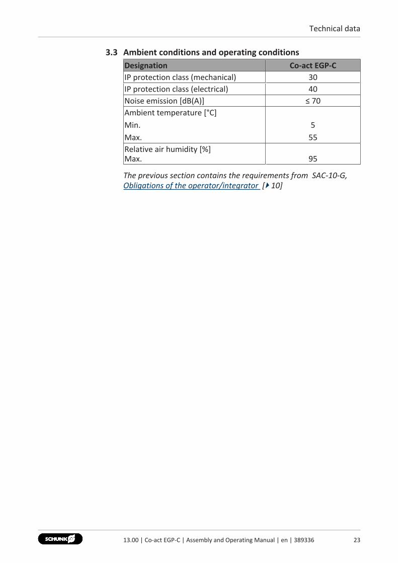
3.3 Ambient conditions and operating conditionsDesignation Co-act EGP-CIP protection class (mechanical) 30IP protection class (electrical) 40Noise emission [dB(A)] ≤ 70Ambient temperature [°C]Min.Max.
555
Relative air humidity [%]Max. 95
The previous section contains the requirements from SAC-10-G,Obligations of the operator/integrator [} 10]
2313.00 | Co-act EGP-C | Assembly and Operating Manual | en | 389336
Design and description
24 13.00 | Co-act EGP-C | Assembly and Operating Manual | en | 389336
4 Design and description
4.1 Design
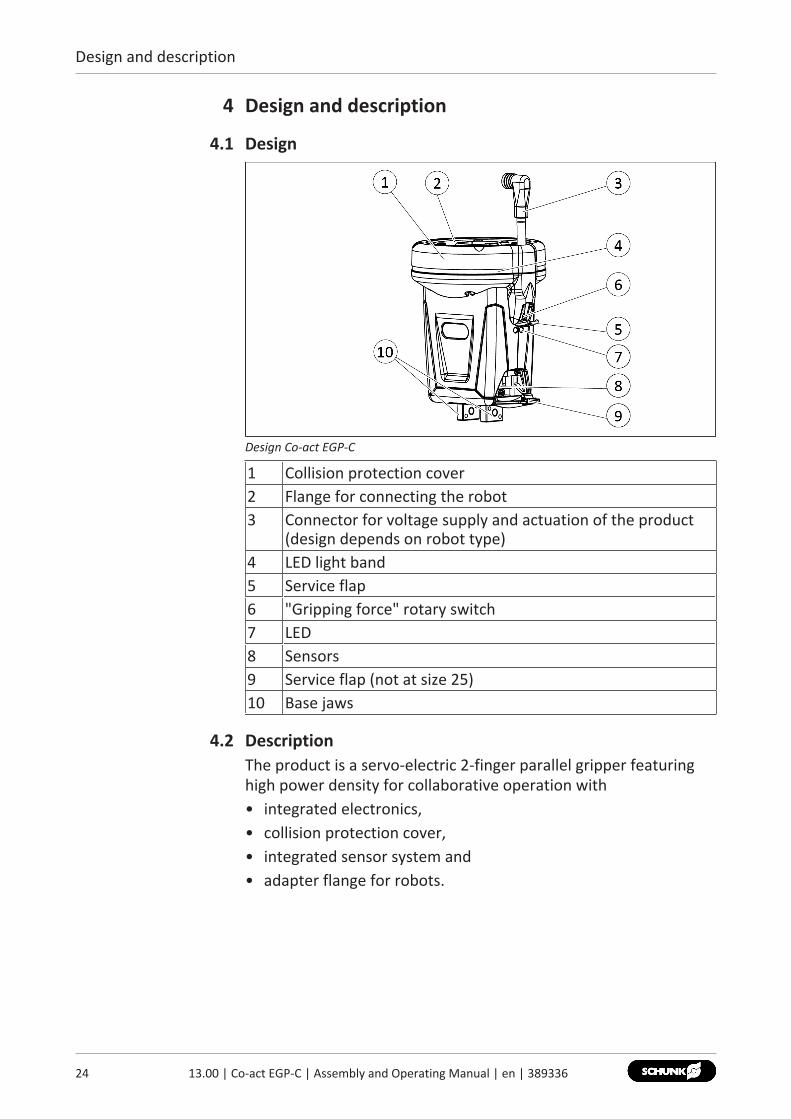
Design Co-act EGP-C
1 Collision protection cover2 Flange for connecting the robot3 Connector for voltage supply and actuation of the product
(design depends on robot type)4 LED light band5 Service flap6 "Gripping force" rotary switch7 LED8 Sensors9 Service flap (not at size 25)10 Base jaws
4.2 DescriptionThe product is a servo-electric 2-finger parallel gripper featuringhigh power density for collaborative operation with• integrated electronics,• collision protection cover,• integrated sensor system and• adapter flange for robots.
Design and description
4.3 Display
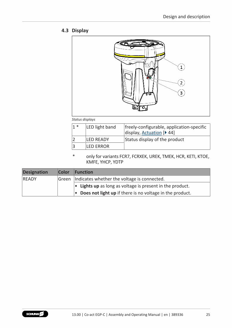
Status displays
1 * LED light band freely-configurable, application-specificdisplay, Actuation [} 44]
2 LED READY Status display of the product3 LED ERROR
* only for variants FCR7, FCRXEK, UREK, TMEK, HCR, KETI, KTOE,KMFE, YHCP, YDTP
Designation Color FunctionREADY Green Indicates whether the voltage is connected.
• Lights up as long as voltage is present in the product.• Does not light up if there is no voltage in the product.
2513.00 | Co-act EGP-C | Assembly and Operating Manual | en | 389336
Design and description
26 13.00 | Co-act EGP-C | Assembly and Operating Manual | en | 389336
Designation Color FunctionERROR Red Indicates whether there is a warning or an error.
• Does not light up when there is no warning or error and theproduct is ready to operate.
• Lights up when there is an "excessive temperature" warning.– The phase current of the motor is limited to Iduration.– The closing and opening times can increase.– Is automatically extinguished when the warning no longer
exists.• Blinks slowly (at approx. 1.2 s intervals) when there is an
"excessive temperature" error.– The product enters an idle phase until it has cooled down.
The commands Open gripper and Close gripper are notprocessed.
– The error must be acknowledged.• Blinks rapidly (at approx. 0.6 s intervals), when the Gripping
force rotary switch is between two switching positions.
Assembly and settings
5 Assembly and settings
5.1 Installing and connectingOverview 1. Check the evenness of the mounting surface, Mechanical
connection [} 27].2. Attach the product to the robot, Mechanical connection [} 27].✓ Observe the tightening torque for the mounting screws.
3. Secure the gripper fingers to the base jaws, Install gripperfingers [} 32].
4. Optional, based on design: Connect the cable for power supplyand actuation, Electrical connection [} 33].
5. Adjust the sensor, if necessary, Adjust the sensors [} 47].6. Adjust gripping force, if necessary, Adjust gripping force
[} 45].
5.2 Mechanical connectionEvenness of themounting surface
The values apply to the whole mounting surface to which theproduct is mounted.Requirements for evenness of the mounting surface (Dimensions in mm)
Edge length Permissible unevenness< 100 < 0.02> 100 < 0.05
Electricallyconductive
The mounting surface must be electrically conductive to ensurethe grounding of the product.The previous section contains the requirements from SAC-11-P,Obligations of the operator/integrator [} 10]
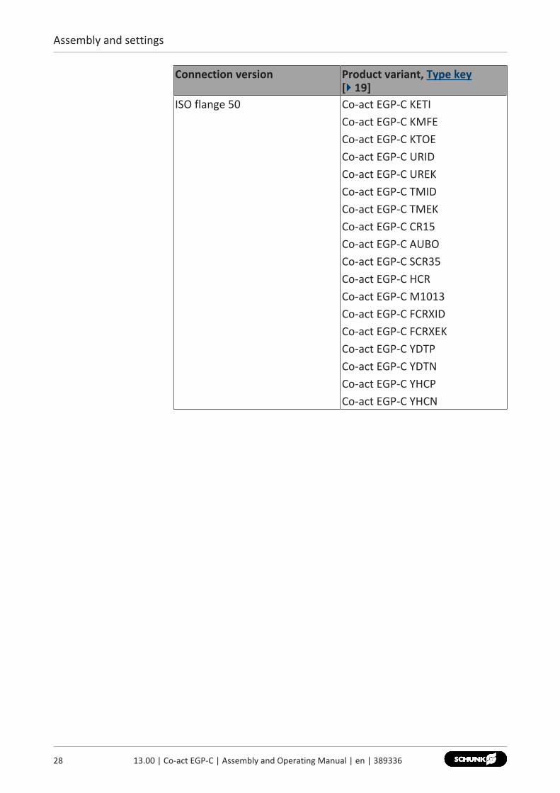
Connections at theproduct
The product has an ISO flange that makes it possible to fasten it tothe robot. The dimensions of the ISO flange vary depending on theproduct variant and depending on the robot type.
NOTEThe product's ID number is located on the name plate. The catalogdata sheet contains the assignment of the ID number of the listedproduct variants.
Connection version Product variant, Type key[} 19]
ISO flange 31.5 Co-act EGP-C FCR7Co-act EGP-C ASSISTA
2713.00 | Co-act EGP-C | Assembly and Operating Manual | en | 389336
Assembly and settings
28 13.00 | Co-act EGP-C | Assembly and Operating Manual | en | 389336
Connection version Product variant, Type key[} 19]
ISO flange 50 Co-act EGP-C KETICo-act EGP-C KMFECo-act EGP-C KTOECo-act EGP-C URIDCo-act EGP-C UREKCo-act EGP-C TMIDCo-act EGP-C TMEKCo-act EGP-C CR15Co-act EGP-C AUBOCo-act EGP-C SCR35Co-act EGP-C HCRCo-act EGP-C M1013Co-act EGP-C FCRXIDCo-act EGP-C FCRXEKCo-act EGP-C YDTPCo-act EGP-C YDTNCo-act EGP-C YHCPCo-act EGP-C YHCN
Assembly and settings
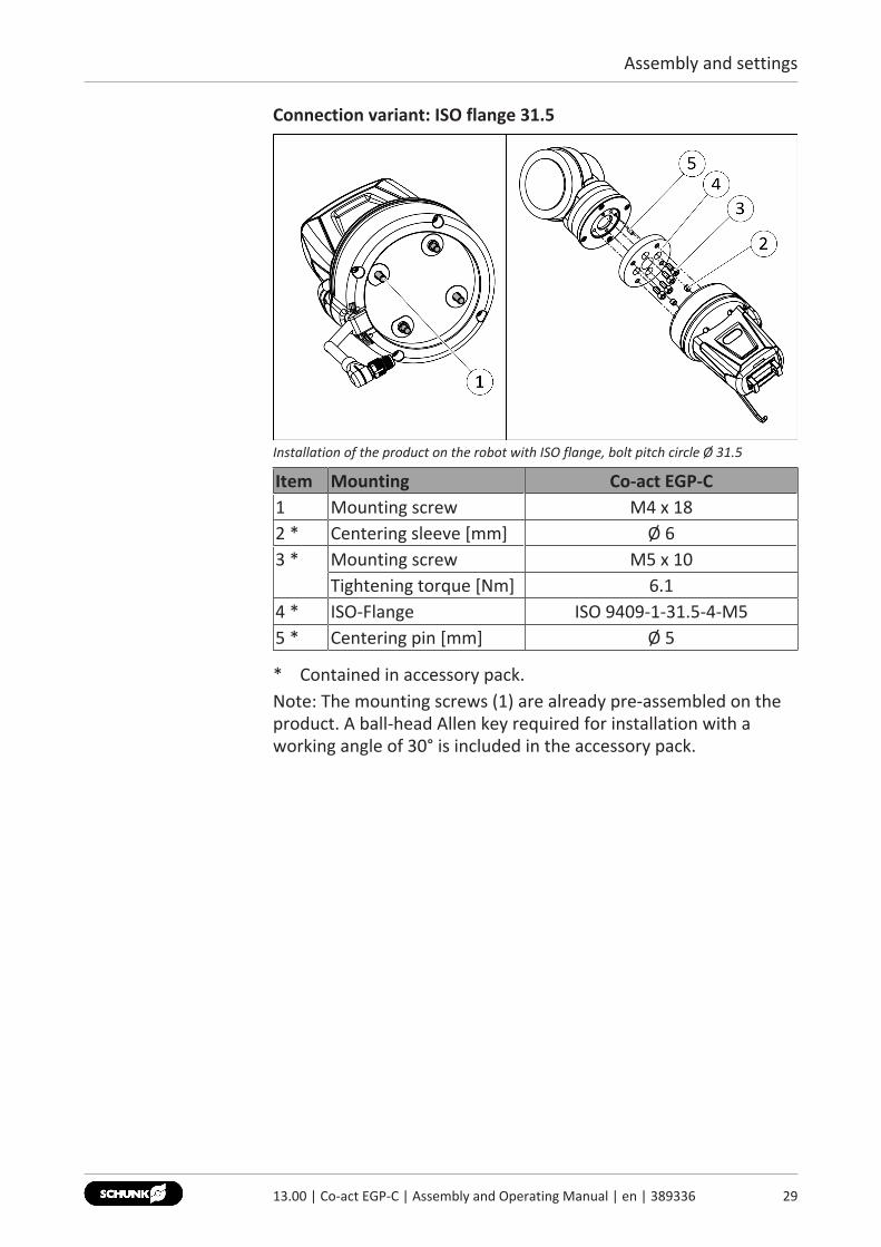
Connection variant: ISO flange 31.5
Installation of the product on the robot with ISO flange, bolt pitch circle Ø 31.5
Item Mounting Co-act EGP-C1 Mounting screw M4 x 182 * Centering sleeve [mm] Ø 63 * Mounting screw M5 x 10
Tightening torque [Nm] 6.14 * ISO-Flange ISO 9409-1-31.5-4-M55 * Centering pin [mm] Ø 5
* Contained in accessory pack.Note: The mounting screws (1) are already pre-assembled on theproduct. A ball-head Allen key required for installation with aworking angle of 30° is included in the accessory pack.
2913.00 | Co-act EGP-C | Assembly and Operating Manual | en | 389336
Assembly and settings
30 13.00 | Co-act EGP-C | Assembly and Operating Manual | en | 389336
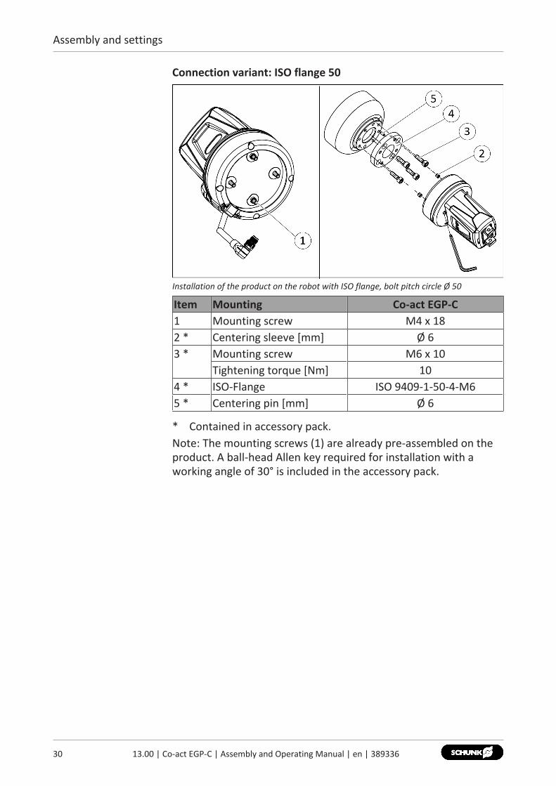
Connection variant: ISO flange 50
Installation of the product on the robot with ISO flange, bolt pitch circle Ø 50
Item Mounting Co-act EGP-C1 Mounting screw M4 x 182 * Centering sleeve [mm] Ø 63 * Mounting screw M6 x 10
Tightening torque [Nm] 104 * ISO-Flange ISO 9409-1-50-4-M65 * Centering pin [mm] Ø 6
* Contained in accessory pack.Note: The mounting screws (1) are already pre-assembled on theproduct. A ball-head Allen key required for installation with aworking angle of 30° is included in the accessory pack.
Assembly and settings
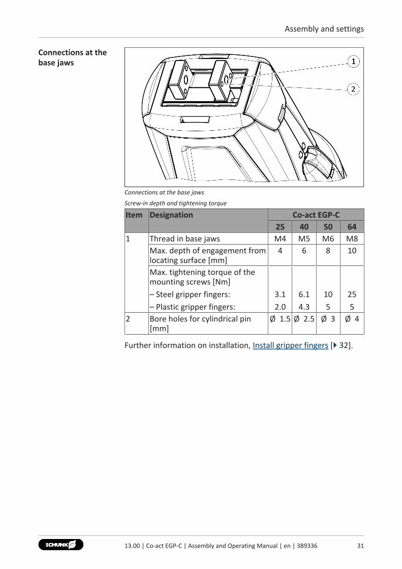
Connections at thebase jaws
Connections at the base jaws
Screw-in depth and tightening torque
Item Designation Co-act EGP-C25 40 50 64
1 Thread in base jaws M4 M5 M6 M8Max. depth of engagement fromlocating surface [mm]
4 6 8 10
Max. tightening torque of themounting screws [Nm]– Steel gripper fingers:– Plastic gripper fingers:
3.12.0
6.14.3
105
255
2 Bore holes for cylindrical pin[mm]
Ø 1.5 Ø 2.5 Ø 3 Ø 4
Further information on installation, Install gripper fingers [} 32].
3113.00 | Co-act EGP-C | Assembly and Operating Manual | en | 389336
Assembly and settings
32 13.00 | Co-act EGP-C | Assembly and Operating Manual | en | 389336
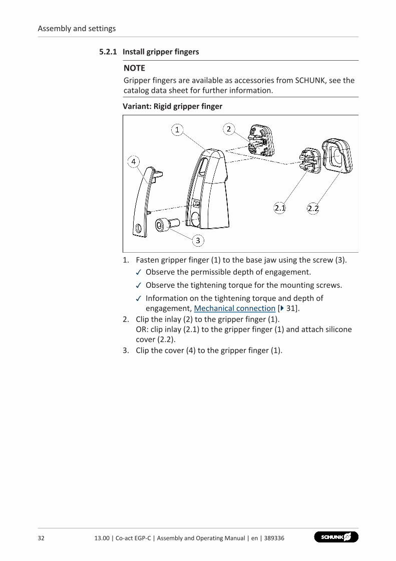
5.2.1 Install gripper fingers
NOTEGripper fingers are available as accessories from SCHUNK, see thecatalog data sheet for further information.
Variant: Rigid gripper finger
1. Fasten gripper finger (1) to the base jaw using the screw (3).✓ Observe the permissible depth of engagement.✓ Observe the tightening torque for the mounting screws.✓ Information on the tightening torque and depth of
engagement, Mechanical connection [} 31].2. Clip the inlay (2) to the gripper finger (1).
OR: clip inlay (2.1) to the gripper finger (1) and attach siliconecover (2.2).
3. Clip the cover (4) to the gripper finger (1).
Assembly and settings
5.3 Electrical connection
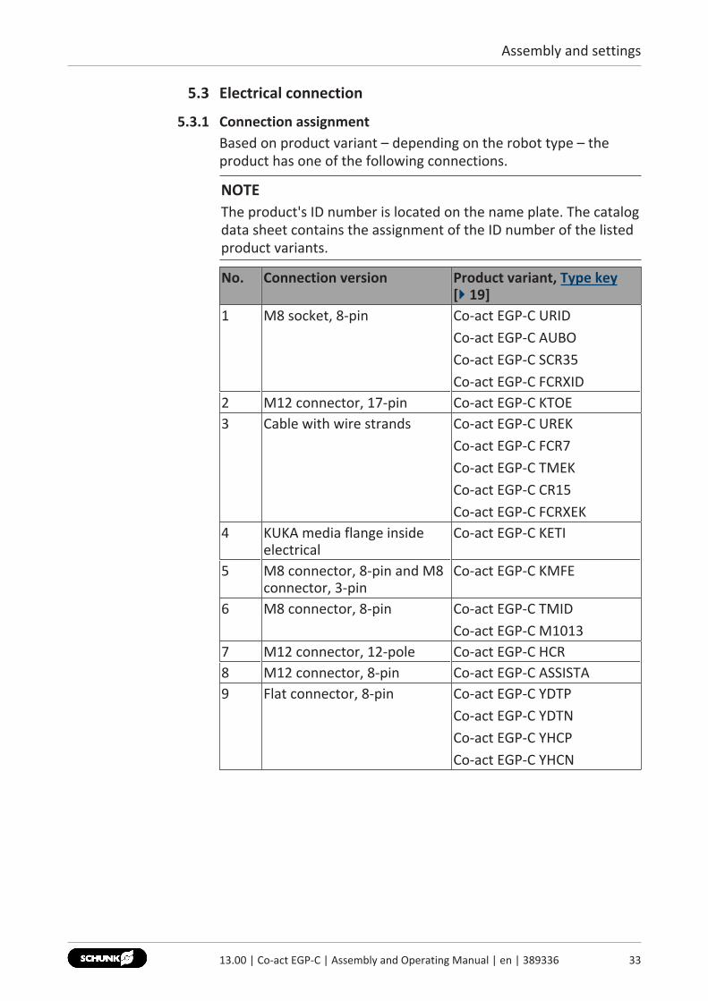
5.3.1 Connection assignmentBased on product variant – depending on the robot type – theproduct has one of the following connections.
NOTEThe product's ID number is located on the name plate. The catalogdata sheet contains the assignment of the ID number of the listedproduct variants.
No. Connection version Product variant, Type key[} 19]
1 M8 socket, 8-pin Co-act EGP-C URIDCo-act EGP-C AUBOCo-act EGP-C SCR35Co-act EGP-C FCRXID
2 M12 connector, 17-pin Co-act EGP-C KTOE3 Cable with wire strands Co-act EGP-C UREK
Co-act EGP-C FCR7Co-act EGP-C TMEKCo-act EGP-C CR15Co-act EGP-C FCRXEK
4 KUKA media flange insideelectrical
Co-act EGP-C KETI
5 M8 connector, 8-pin and M8connector, 3-pin
Co-act EGP-C KMFE
6 M8 connector, 8-pin Co-act EGP-C TMIDCo-act EGP-C M1013
7 M12 connector, 12-pole Co-act EGP-C HCR8 M12 connector, 8-pin Co-act EGP-C ASSISTA9 Flat connector, 8-pin Co-act EGP-C YDTP
Co-act EGP-C YDTNCo-act EGP-C YHCPCo-act EGP-C YHCN
3313.00 | Co-act EGP-C | Assembly and Operating Manual | en | 389336
Assembly and settings
34 13.00 | Co-act EGP-C | Assembly and Operating Manual | en | 389336
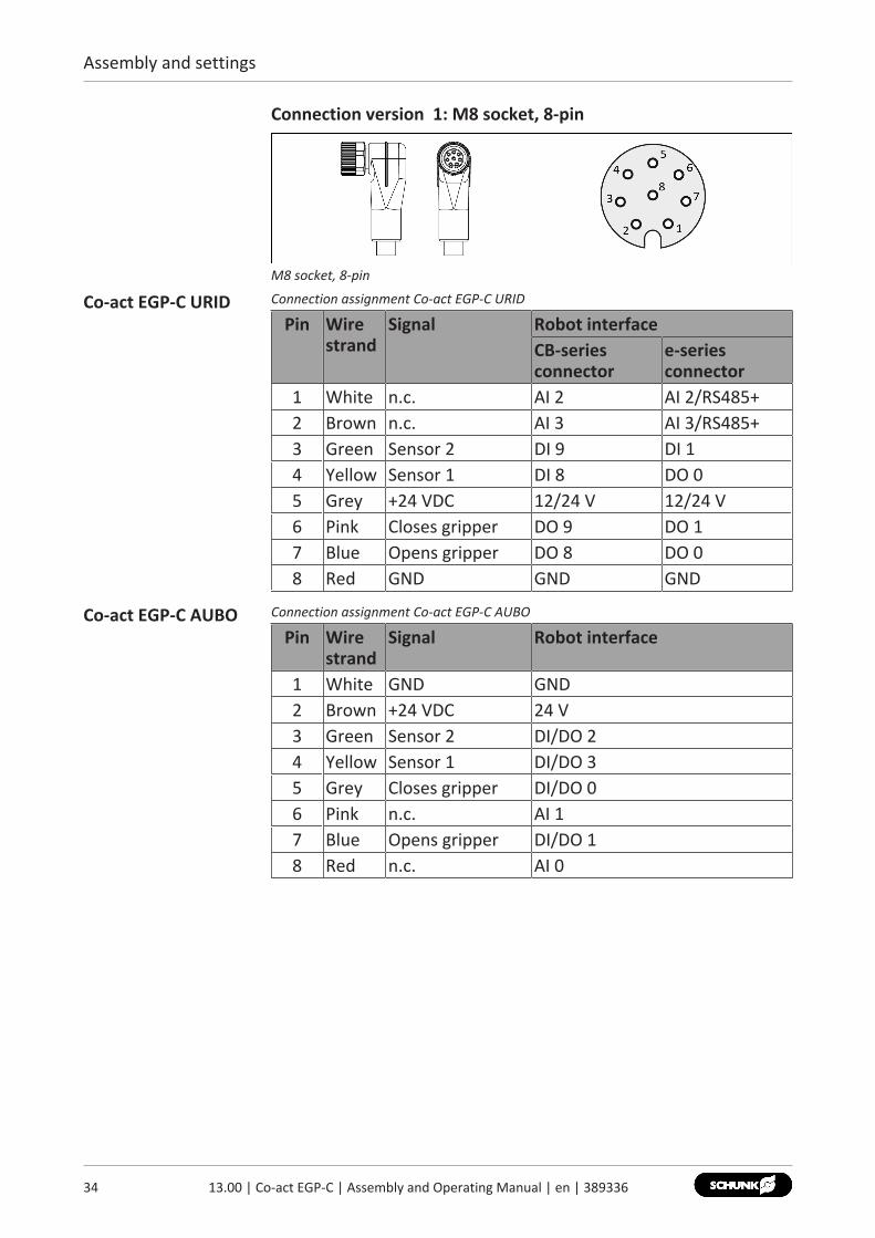
Connection version 1: M8 socket, 8-pin
M8 socket, 8-pin
Co-act EGP-C URID Connection assignment Co-act EGP-C URID
Pin Wirestrand
Signal Robot interfaceCB-seriesconnector
e-seriesconnector
1 White n.c. AI 2 AI 2/RS485+2 Brown n.c. AI 3 AI 3/RS485+3 Green Sensor 2 DI 9 DI 14 Yellow Sensor 1 DI 8 DO 05 Grey +24 VDC 12/24 V 12/24 V6 Pink Closes gripper DO 9 DO 17 Blue Opens gripper DO 8 DO 08 Red GND GND GND
Co-act EGP-C AUBO Connection assignment Co-act EGP-C AUBO
Pin Wirestrand
Signal Robot interface
1 White GND GND2 Brown +24 VDC 24 V3 Green Sensor 2 DI/DO 24 Yellow Sensor 1 DI/DO 35 Grey Closes gripper DI/DO 06 Pink n.c. AI 17 Blue Opens gripper DI/DO 18 Red n.c. AI 0
Assembly and settings
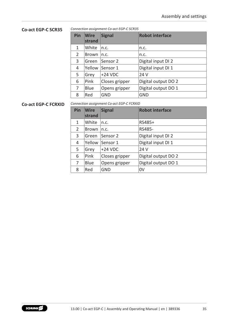
Co-act EGP-C SCR35 Connection assignment Co-act EGP-C SCR35
Pin Wirestrand
Signal Robot interface
1 White n.c. n.c.2 Brown n.c. n.c.3 Green Sensor 2 Digital input DI 24 Yellow Sensor 1 Digital input DI 15 Grey +24 VDC 24 V6 Pink Closes gripper Digital output DO 27 Blue Opens gripper Digital output DO 18 Red GND GND
Co-act EGP-C FCRXID Connection assignment Co-act EGP-C FCRXID
Pin Wirestrand
Signal Robot interface
1 White n.c. RS485+2 Brown n.c. RS485-3 Green Sensor 2 Digital input DI 24 Yellow Sensor 1 Digital input DI 15 Grey +24 VDC 24 V6 Pink Closes gripper Digital output DO 27 Blue Opens gripper Digital output DO 18 Red GND 0V
3513.00 | Co-act EGP-C | Assembly and Operating Manual | en | 389336
Assembly and settings
36 13.00 | Co-act EGP-C | Assembly and Operating Manual | en | 389336
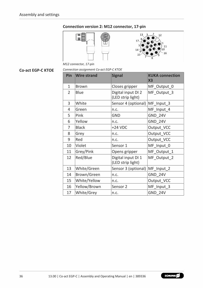
Connection version 2: M12 connector, 17-pin
M12 connector, 17-pin
Co-act EGP-C KTOE Connection assignment Co-act EGP-C KTOE
Pin Wire strand Signal KUKA connectionX3
1 Brown Closes gripper MF_Output_02 Blue Digital input DI 2
(LED strip light)MF_Output_3
3 White Sensor 4 (optional) MF_Input_34 Green n.c. MF_Input_45 Pink GND GND_24V6 Yellow n.c. GND_24V7 Black +24 VDC Output_VCC8 Grey n.c. Output_VCC9 Red n.c. Output_VCC
10 Violet Sensor 1 MF_Input_011 Grey/Pink Opens gripper MF_Output_112 Red/Blue Digital input DI 1
(LED strip light)MF_Output_2
13 White/Green Sensor 3 (optional) MF_Input_214 Brown/Green n.c. GND_24V15 White/Yellow n.c. Output_VCC16 Yellow/Brown Sensor 2 MF_Input_317 White/Grey n.c. GND_24V
Assembly and settings
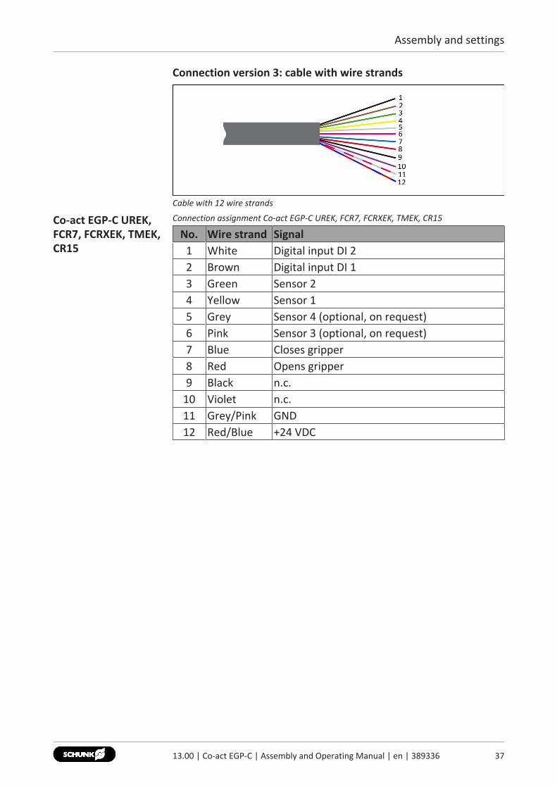
Connection version 3: cable with wire strands
Cable with 12 wire strands
Co-act EGP-C UREK,FCR7, FCRXEK, TMEK,CR15
Connection assignment Co-act EGP-C UREK, FCR7, FCRXEK, TMEK, CR15
No. Wire strand Signal1 White Digital input DI 22 Brown Digital input DI 13 Green Sensor 24 Yellow Sensor 15 Grey Sensor 4 (optional, on request)6 Pink Sensor 3 (optional, on request)7 Blue Closes gripper8 Red Opens gripper9 Black n.c.
10 Violet n.c.11 Grey/Pink GND12 Red/Blue +24 VDC
3713.00 | Co-act EGP-C | Assembly and Operating Manual | en | 389336
Assembly and settings
38 13.00 | Co-act EGP-C | Assembly and Operating Manual | en | 389336
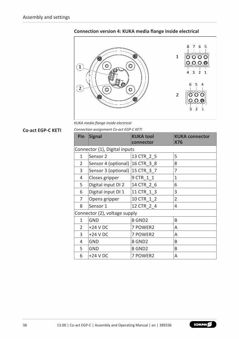
Connection version 4: KUKA media flange inside electrical
KUKA media flange inside electrical
Co-act EGP-C KETI Connection assignment Co-act EGP-C KETI
Pin Signal KUKA toolconnector
KUKA connectorX76
Connector (1), Digital inputs1 Sensor 2 13 CTR_2_5 52 Sensor 4 (optional) 16 CTR_3_8 83 Sensor 3 (optional) 15 CTR_3_7 74 Closes gripper 9 CTR_1_1 15 Digital input DI 2 14 CTR_2_6 66 Digital input DI 1 11 CTR_1_3 37 Opens gripper 10 CTR_1_2 28 Sensor 1 12 CTR_2_4 4
Connector (2), voltage supply1 GND 8 GND2 B2 +24 V DC 7 POWER2 A3 +24 V DC 7 POWER2 A4 GND 8 GND2 B5 GND 8 GND2 B6 +24 V DC 7 POWER2 A
Assembly and settings
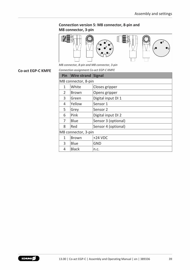
Connection version 5: M8 connector, 8-pin and M8 connector, 3-pin
M8 connector, 8-pin and M8 connector, 3-pin
Co-act EGP-C KMFE Connection assignment Co-act EGP-C KMFE
Pin Wire strand SignalM8 connector, 8-pin
1 White Closes gripper2 Brown Opens gripper3 Green Digital input DI 14 Yellow Sensor 15 Grey Sensor 26 Pink Digital input DI 27 Blue Sensor 3 (optional)8 Red Sensor 4 (optional)
M8 connector, 3-pin1 Brown +24 VDC3 Blue GND4 Black n.c.
3913.00 | Co-act EGP-C | Assembly and Operating Manual | en | 389336
Assembly and settings
40 13.00 | Co-act EGP-C | Assembly and Operating Manual | en | 389336
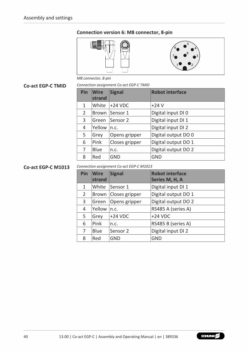
Connection version 6: M8 connector, 8-pin
M8 connector, 8-pin
Co-act EGP-C TMID Connection assignment Co-act EGP-C TMID
Pin Wirestrand
Signal Robot interface
1 White +24 VDC +24 V2 Brown Sensor 1 Digital input DI 03 Green Sensor 2 Digital input DI 14 Yellow n.c. Digital input DI 25 Grey Opens gripper Digital output DO 06 Pink Closes gripper Digital output DO 17 Blue n.c. Digital output DO 28 Red GND GND
Co-act EGP-C M1013 Connection assignment Co-act EGP-C M1013
Pin Wirestrand
Signal Robot interface Series M, H, A
1 White Sensor 1 Digital input DI 12 Brown Closes gripper Digital output DO 13 Green Opens gripper Digital output DO 24 Yellow n.c. RS485 A (series A)5 Grey +24 VDC +24 VDC6 Pink n.c. RS485 B (series A)7 Blue Sensor 2 Digital input DI 28 Red GND GND
Assembly and settings
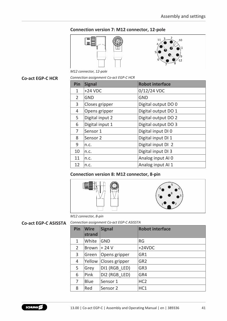
Connection version 7: M12 connector, 12-pole
M12 connector, 12-pole
Co-act EGP-C HCR Connection assignment Co-act EGP-C HCR
Pin Signal Robot interface1 +24 VDC 0/12/24 VDC2 GND GND3 Closes gripper Digital output DO 04 Opens gripper Digital output DO 15 Digital input 2 Digital output DO 26 Digital input 1 Digital output DO 37 Sensor 1 Digital input DI 08 Sensor 2 Digital input DI 19 n.c. Digital input DI 2
10 n.c. Digital input DI 311 n.c. Analog input AI 012 n.c. Analog input AI 1
Connection version 8: M12 connector, 8-pin
M12 connector, 8-pin
Co-act EGP-C ASISSTA Connection assignment Co-act EGP-C ASISSTA
Pin Wirestrand
Signal Robot interface
1 White GND RG2 Brown + 24 V +24VDC3 Green Opens gripper GR14 Yellow Closes gripper GR25 Grey DI1 (RGB_LED) GR36 Pink DI2 (RGB_LED) GR47 Blue Sensor 1 HC28 Red Sensor 2 HC1
4113.00 | Co-act EGP-C | Assembly and Operating Manual | en | 389336
Assembly and settings
42 13.00 | Co-act EGP-C | Assembly and Operating Manual | en | 389336
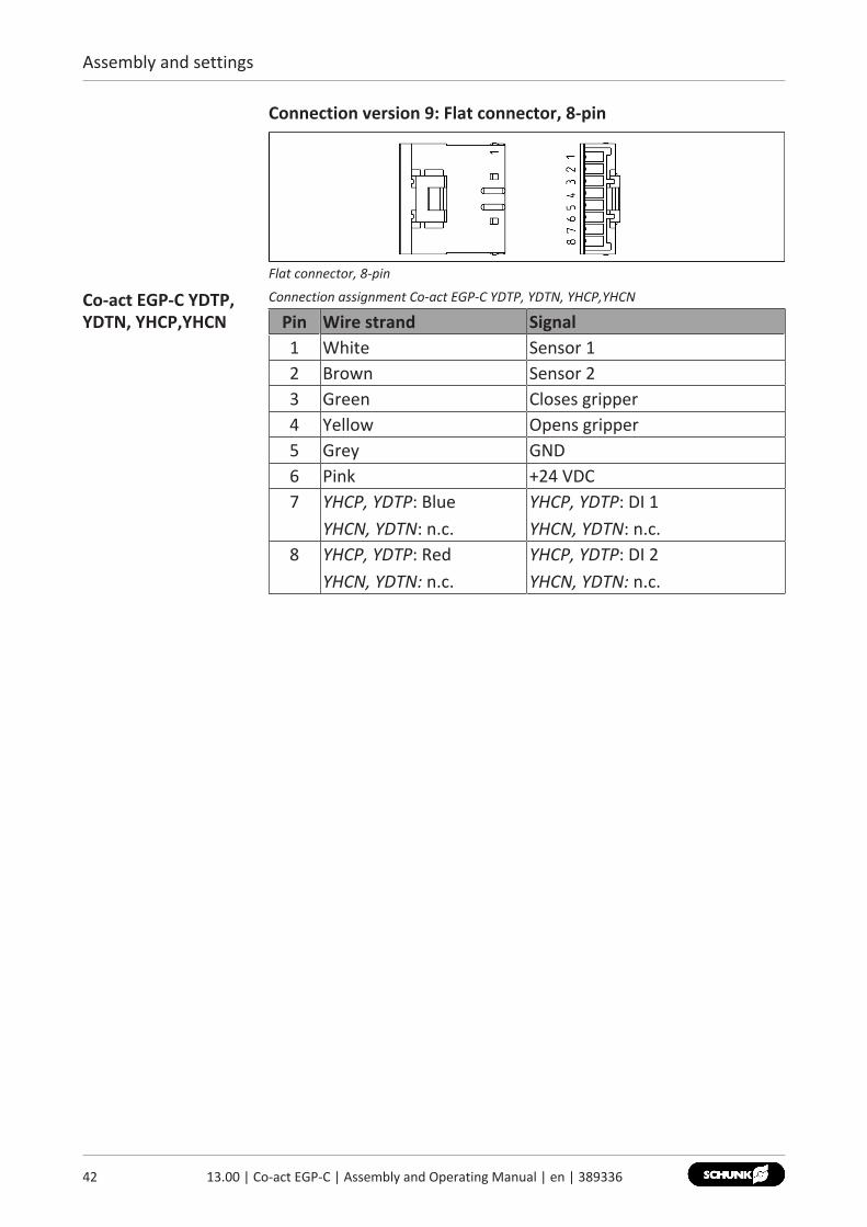
Connection version 9: Flat connector, 8-pin
Flat connector, 8-pin
Co-act EGP-C YDTP,YDTN, YHCP,YHCN
Connection assignment Co-act EGP-C YDTP, YDTN, YHCP,YHCN
Pin Wire strand Signal1 White Sensor 12 Brown Sensor 23 Green Closes gripper4 Yellow Opens gripper5 Grey GND6 Pink +24 VDC7 YHCP, YDTP: Blue
YHCN, YDTN: n.c.YHCP, YDTP: DI 1YHCN, YDTN: n.c.
8 YHCP, YDTP: RedYHCN, YDTN: n.c.
YHCP, YDTP: DI 2YHCN, YDTN: n.c.
Assembly and settings
5.3.2 ActuationTruth table The following truth tables show the actuation of the digital inputs
during possible commands by the superordinated control unit.Current input per digital input amounts to max. I=10 mA.Depending on the connection variant, the digital inputs are useddifferently, Connection assignment [} 33].
NOTEFor variant URID, the digital inputs are listed in switching type"NPN".
Actuation Opens gripper / Closes gripperFunction Digital input
Opens gripper
Closes gripper
De-energized drive(shutdown, motor is short-circuited)
0 0
Opens gripper 1 0Closes gripper 0 1Rectify error(shutdown, motor is short-circuited)
1 1
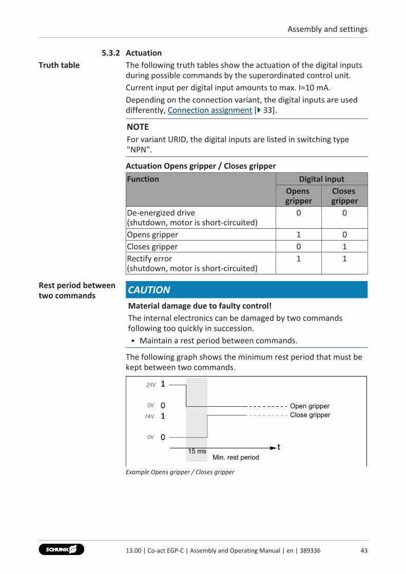
Rest period betweentwo commands CAUTION
Material damage due to faulty control!The internal electronics can be damaged by two commandsfollowing too quickly in succession.• Maintain a rest period between commands.
The following graph shows the minimum rest period that must bekept between two commands.
Min. rest period
Open gripperClose gripper
15 ms
Example Opens gripper / Closes gripper
4313.00 | Co-act EGP-C | Assembly and Operating Manual | en | 389336
Assembly and settings
44 13.00 | Co-act EGP-C | Assembly and Operating Manual | en | 389336
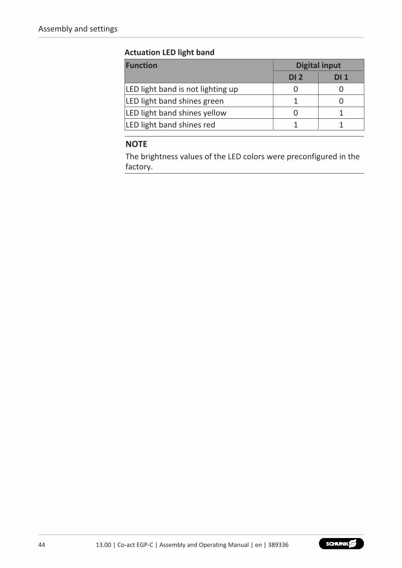
Actuation LED light bandFunction Digital input
DI 2 DI 1LED light band is not lighting up 0 0LED light band shines green 1 0LED light band shines yellow 0 1LED light band shines red 1 1
NOTEThe brightness values of the LED colors were preconfigured in thefactory.
Assembly and settings
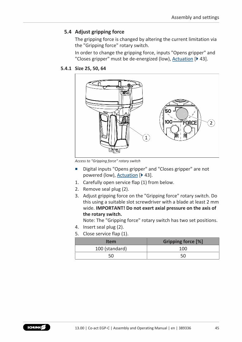
5.4 Adjust gripping forceThe gripping force is changed by altering the current limitation viathe "Gripping force" rotary switch.In order to change the gripping force, inputs "Opens gripper" and"Closes gripper" must be de-energized (low), Actuation [} 43].
5.4.1 Size 25, 50, 64
Access to "Gripping force" rotary switch
■ Digital inputs "Opens gripper" and "Closes gripper" are notpowered (low), Actuation [} 43].
1. Carefully open service flap (1) from below.2. Remove seal plug (2).3. Adjust gripping force on the "Gripping force" rotary switch. Do
this using a suitable slot screwdriver with a blade at least 2 mmwide. IMPORTANT! Do not exert axial pressure on the axis ofthe rotary switch.Note: The "Gripping force" rotary switch has two set positions.
4. Insert seal plug (2).5. Close service flap (1).
Item Gripping force [%]100 (standard) 100
50 50
4513.00 | Co-act EGP-C | Assembly and Operating Manual | en | 389336
Assembly and settings
46 13.00 | Co-act EGP-C | Assembly and Operating Manual | en | 389336
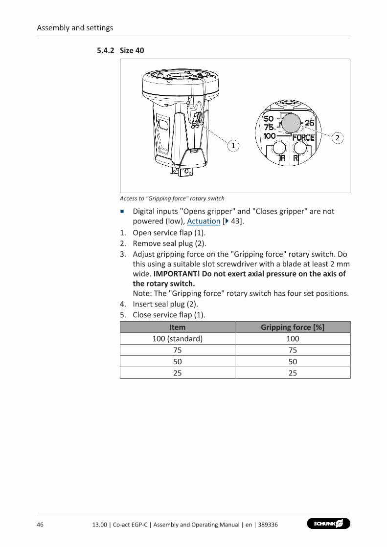
5.4.2 Size 40
Access to "Gripping force" rotary switch
■ Digital inputs "Opens gripper" and "Closes gripper" are notpowered (low), Actuation [} 43].
1. Open service flap (1).2. Remove seal plug (2).3. Adjust gripping force on the "Gripping force" rotary switch. Do
this using a suitable slot screwdriver with a blade at least 2 mmwide. IMPORTANT! Do not exert axial pressure on the axis ofthe rotary switch.Note: The "Gripping force" rotary switch has four set positions.
4. Insert seal plug (2).5. Close service flap (1).
Item Gripping force [%]100 (standard) 100
75 7550 5025 25
Assembly and settings
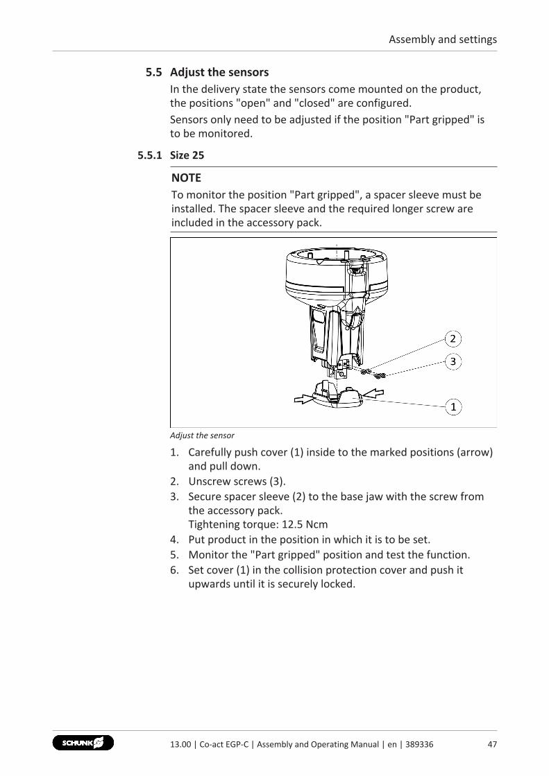
5.5 Adjust the sensorsIn the delivery state the sensors come mounted on the product,the positions "open" and "closed" are configured.Sensors only need to be adjusted if the position "Part gripped" isto be monitored.
5.5.1 Size 25
NOTETo monitor the position "Part gripped", a spacer sleeve must beinstalled. The spacer sleeve and the required longer screw areincluded in the accessory pack.
Adjust the sensor
1. Carefully push cover (1) inside to the marked positions (arrow)and pull down.
2. Unscrew screws (3).3. Secure spacer sleeve (2) to the base jaw with the screw from
the accessory pack.Tightening torque: 12.5 Ncm
4. Put product in the position in which it is to be set.5. Monitor the "Part gripped" position and test the function.6. Set cover (1) in the collision protection cover and push it
upwards until it is securely locked.
4713.00 | Co-act EGP-C | Assembly and Operating Manual | en | 389336
Assembly and settings
48 13.00 | Co-act EGP-C | Assembly and Operating Manual | en | 389336
5.5.2 Size 40, 50, 64
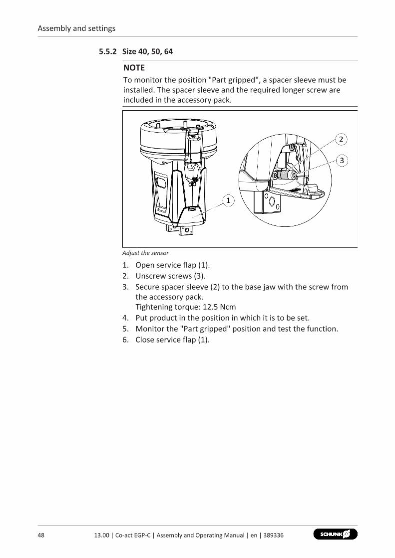
NOTETo monitor the position "Part gripped", a spacer sleeve must beinstalled. The spacer sleeve and the required longer screw areincluded in the accessory pack.
Adjust the sensor
1. Open service flap (1).2. Unscrew screws (3).3. Secure spacer sleeve (2) to the base jaw with the screw from
the accessory pack.Tightening torque: 12.5 Ncm
4. Put product in the position in which it is to be set.5. Monitor the "Part gripped" position and test the function.6. Close service flap (1).
Start-up
6 Start-upCarrying out the commissioning, the risk assessment and thedocumentation of the safety verification for integration must becarried out upon every modification of the customer-specificapplication (e.g. when gripping other workpieces).If existing settings unchanged, e.g. grip width and workpieceweight, this risk potential can be substantiated as non-critical byperforming the risk assessment again. The information/queries inthe check-list (Commissioning checklist [} 58]) must be takeninto account in the risk assessment.In order to facilitate the integration of the product in a machine, agantry or a robot system, it is possible to use the checklist(Commissioning checklist [} 58]) to check and document themain points of integration.
NOTEThe checklist does not lead to full compliance with the legalrequirements applicable to the end effector, Commissioningchecklist [} 58].
The previous section contains the requirements from SAC-06-G,SAC-09-G, Obligations of the operator/integrator [} 10]
4913.00 | Co-act EGP-C | Assembly and Operating Manual | en | 389336
Troubleshooting
50 13.00 | Co-act EGP-C | Assembly and Operating Manual | en | 389336
7 Troubleshooting
7.1 Product does not movePossible cause Corrective actionBase jaws jam in housing, e.g. mountingsurface is not sufficiently even.
Check the evenness of the mounting surface.Mechanical connection [} 27]Loosen the mounting screws of the productand actuate the product again.
Sensor incorrectly set. / Sensor ismisaligned.
Adjust sensor so that it does not obstructthe traverse path of the product.Distance to the querying mechanics:approx.0.2 mm
Power supply connected incorrectly. Check the power supply.Electrical connection [} 33]
Internal fuse has triggered. Send the product to SCHUNK with a repairorder.
7.2 Product does not execute a complete strokePossible cause Corrective actionMounting surface is not sufficiently flat. Check the evenness of the mounting surface.
Mechanical connection [} 27]Breakage of components, e.g. byoverloading.
Send the product to SCHUNK with a repairorder.
7.3 Product opens or closes jerkilyPossible cause Corrective actionMounting surface is not sufficiently flat. Check the evenness of the mounting surface.
Mechanical connection [} 27]Loading too large. Check permissible weight and length of the
gripper fingers.Technical data [} 19]
7.4 Gripping force too lowPossible cause Corrective actionWrong gripping pre-selection. Check rotary switch setting.
Electrical connection [} 33]Check layout of the product. Meanwhileobserve the maximum workpiece weight,see Catalog Data Sheet.Technical data [} 19]
Troubleshooting
7.5 Opening and closing times are not achievedPossible cause Corrective actionLoading too large. Check permissible weight and length of the
gripper fingers.
7.6 Electric signals are not transmitted?Possible cause Corrective actionCable connected incorrectly. Check that the plug is connected properly.
Electrical connection [} 33]Strands swapped. Check pin allocation.
Electrical connection [} 33]
7.7 Faults which are displayed via LED ErrorPossible cause LED "Error" Corrective actionRotary switch is in anintermediate position
LED blinks at 0.6 s intervals
Turn rotary switch to a marked position.
Error overheating
LED blinks at 1.2 s intervals
Let product cool down and acknowledgeerror.Acknowledge error [} 51]
Warning overheating
LED glowscontinuously
The warning is automatically deleted whenthe product has cooled down.
7.8 Acknowledge error1. Wait until the product has cooled down.2. Actuate both digital inlets, "Opens gripper" and "Closes
gripper", with high.OR: Disconnect voltage supply and reconnect.
✔ The "ERROR" LED goes out. The error is acknowledged.
5113.00 | Co-act EGP-C | Assembly and Operating Manual | en | 389336
Maintenance
52 13.00 | Co-act EGP-C | Assembly and Operating Manual | en | 389336
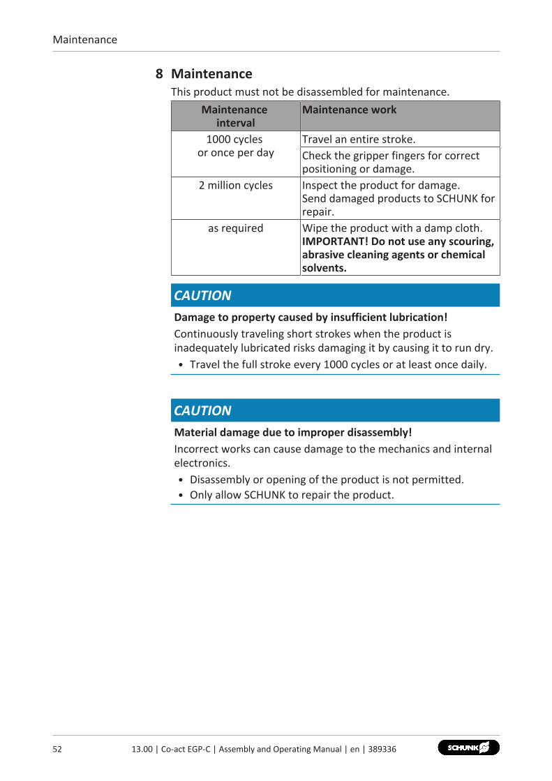
8 MaintenanceThis product must not be disassembled for maintenance.
Maintenance interval
Maintenance work
1000 cycles or once per day
Travel an entire stroke.Check the gripper fingers for correctpositioning or damage.
2 million cycles Inspect the product for damage.Send damaged products to SCHUNK forrepair.
as required Wipe the product with a damp cloth.IMPORTANT! Do not use any scouring,abrasive cleaning agents or chemicalsolvents.
CAUTIONDamage to property caused by insufficient lubrication!Continuously traveling short strokes when the product isinadequately lubricated risks damaging it by causing it to run dry.• Travel the full stroke every 1000 cycles or at least once daily.
CAUTIONMaterial damage due to improper disassembly!Incorrect works can cause damage to the mechanics and internalelectronics.• Disassembly or opening of the product is not permitted.• Only allow SCHUNK to repair the product.
EU-Declaration of Conformity
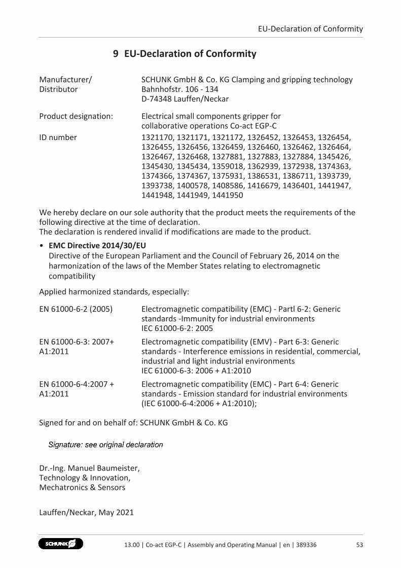
9 EU-Declaration of Conformity
Manufacturer/Distributor
SCHUNK GmbH & Co. KG Clamping and gripping technology Bahnhofstr. 106 - 134 D-74348 Lauffen/Neckar
Product designation: Electrical small components gripper for collaborative operations Co-act EGP-C
ID number 1321170, 1321171, 1321172, 1326452, 1326453, 1326454,1326455, 1326456, 1326459, 1326460, 1326462, 1326464,1326467, 1326468, 1327881, 1327883, 1327884, 1345426,1345430, 1345434, 1359018, 1362939, 1372938, 1374363,1374366, 1374367, 1375931, 1386531, 1386711, 1393739,1393738, 1400578, 1408586, 1416679, 1436401, 1441947,1441948, 1441949, 1441950
We hereby declare on our sole authority that the product meets the requirements of thefollowing directive at the time of declaration. The declaration is rendered invalid if modifications are made to the product.• EMC Directive 2014/30/EU
Directive of the European Parliament and the Council of February 26, 2014 on theharmonization of the laws of the Member States relating to electromagneticcompatibility
Applied harmonized standards, especially:
EN 61000-6-2 (2005) Electromagnetic compatibility (EMC) - Partl 6-2: Generic standards -Immunity for industrial environments IEC 61000-6-2: 2005
EN 61000-6-3: 2007+A1:2011
Electromagnetic compatibility (EMV) - Part 6-3: Generic standards - Interference emissions in residential, commercial,industrial and light industrial environments IEC 61000-6-3: 2006 + A1:2010
EN 61000-6-4:2007 +A1:2011
Electromagnetic compatibility (EMC) - Part 6-4: Generic standards - Emission standard for industrial environments(IEC 61000-6-4:2006 + A1:2010);
Signed for and on behalf of: SCHUNK GmbH & Co. KG
Dr.-Ing. Manuel Baumeister,Technology & Innovation, Mechatronics & Sensors
Lauffen/Neckar, May 2021
5313.00 | Co-act EGP-C | Assembly and Operating Manual | en | 389336
Translation of original declaration of incorporation
54 13.00 | Co-act EGP-C | Assembly and Operating Manual | en | 389336
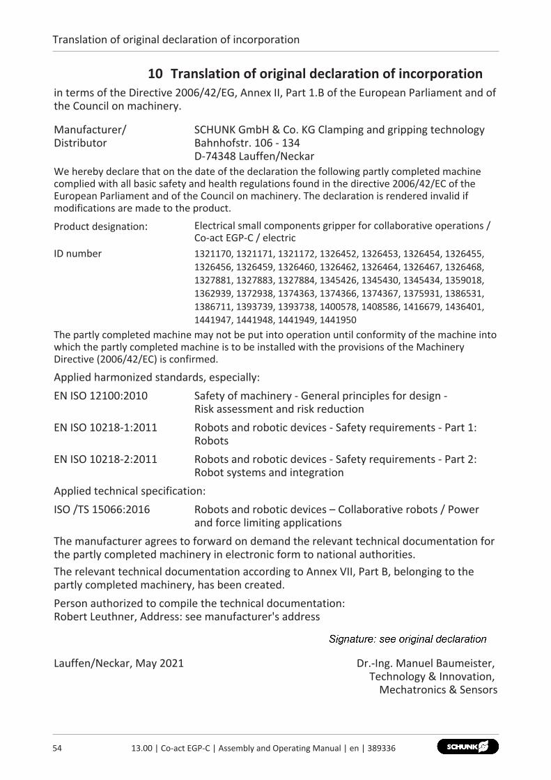
10 Translation of original declaration of incorporationin terms of the Directive 2006/42/EG, Annex II, Part 1.B of the European Parliament and ofthe Council on machinery.
Manufacturer/Distributor
SCHUNK GmbH & Co. KG Clamping and gripping technology Bahnhofstr. 106 - 134 D-74348 Lauffen/Neckar
We hereby declare that on the date of the declaration the following partly completed machinecomplied with all basic safety and health regulations found in the directive 2006/42/EC of theEuropean Parliament and of the Council on machinery. The declaration is rendered invalid ifmodifications are made to the product.
Product designation: Electrical small components gripper for collaborative operations /Co-act EGP-C / electric
ID number 1321170, 1321171, 1321172, 1326452, 1326453, 1326454, 1326455,1326456, 1326459, 1326460, 1326462, 1326464, 1326467, 1326468,1327881, 1327883, 1327884, 1345426, 1345430, 1345434, 1359018,1362939, 1372938, 1374363, 1374366, 1374367, 1375931, 1386531,1386711, 1393739, 1393738, 1400578, 1408586, 1416679, 1436401,1441947, 1441948, 1441949, 1441950
The partly completed machine may not be put into operation until conformity of the machine intowhich the partly completed machine is to be installed with the provisions of the MachineryDirective (2006/42/EC) is confirmed.
Applied harmonized standards, especially:EN ISO 12100:2010 Safety of machinery - General principles for design -
Risk assessment and risk reductionEN ISO 10218-1:2011 Robots and robotic devices - Safety requirements - Part 1:
RobotsEN ISO 10218-2:2011 Robots and robotic devices - Safety requirements - Part 2:
Robot systems and integrationApplied technical specification:ISO /TS 15066:2016 Robots and robotic devices – Collaborative robots / Power
and force limiting applicationsThe manufacturer agrees to forward on demand the relevant technical documentation forthe partly completed machinery in electronic form to national authorities.The relevant technical documentation according to Annex VII, Part B, belonging to thepartly completed machinery, has been created.Person authorized to compile the technical documentation: Robert Leuthner, Address: see manufacturer's address
Lauffen/Neckar, May 2021 Dr.-Ing. Manuel Baumeister, Technology & Innovation,
Mechatronics & Sensors

Annex to Declaration of Incorporation
11 Annex to Declaration of Incorporationaccording 2006/42/EG, Annex II, No. 1 B
1.Description of the essential health and safety requirements pursuant to 2006/42/EC,Annex I that are applicable and that have been fulfilled with:
Product designation Electrical small components gripper for collaborative operationsType designation Co-act EGP-CID number 1321170, 1321171, 1321172, 1326452, 1326453, 1326454, 1326455,
1326456, 1326459, 1326460, 1326462, 1326464, 1326467, 1326468,1327881, 1327883, 1327884, 1345426, 1345430, 1345434, 1359018,1362939, 1372938, 1374363, 1374366, 1374367, 1375931, 1386531,1386711, 1393739, 1393738, 1400578, 1408586, 1416679, 1436401,1441947, 1441948, 1441949, 1441950
To be provided by the System Integrator for the overall machine ⇓Fulfilled for the scope of the partly completed machine ⇓
Not relevant ⇓
1.1 Essential Requirements1.1.1 Definitions X1.1.2 Principles of safety integration X1.1.3 Materials and products X1.1.4 Lighting X1.1.5 Design of machinery to facilitate its handling X1.1.6 Ergonomics X1.1.7 Operating positions X1.1.8 Seating X
1.2 Control Systems1.2.1 Safety and reliability of control systems X1.2.2 Control devices X1.2.3 Starting X1.2.4 Stopping1.2.4.1 Normal stop X1.2.4.2 Operational stop X1.2.4.3 Emergency stop X1.2.4.4 Assembly of machinery X1.2.5 Selection of control or operating modes X1.2.6 Failure of the power supply X
1.3 Protection against mechanical hazards1.3.1 Risk of loss of stability X
5513.00 | Co-act EGP-C | Assembly and Operating Manual | en | 389336
Annex to Declaration of Incorporation
56 13.00 | Co-act EGP-C | Assembly and Operating Manual | en | 389336
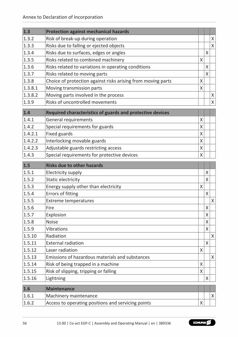
1.3 Protection against mechanical hazards1.3.2 Risk of break-up during operation X1.3.3 Risks due to falling or ejected objects X1.3.4 Risks due to surfaces, edges or angles X1.3.5 Risks related to combined machinery X1.3.6 Risks related to variations in operating conditions X1.3.7 Risks related to moving parts X1.3.8 Choice of protection against risks arising from moving parts X1.3.8.1 Moving transmission parts X1.3.8.2 Moving parts involved in the process X1.3.9 Risks of uncontrolled movements X
1.4 Required characteristics of guards and protective devices1.4.1 General requirements X1.4.2 Special requirements for guards X1.4.2.1 Fixed guards X1.4.2.2 Interlocking movable guards X1.4.2.3 Adjustable guards restricting access X1.4.3 Special requirements for protective devices X
1.5 Risks due to other hazards1.5.1 Electricity supply X1.5.2 Static electricity X1.5.3 Energy supply other than electricity X1.5.4 Errors of fitting X1.5.5 Extreme temperatures X1.5.6 Fire X1.5.7 Explosion X1.5.8 Noise X1.5.9 Vibrations X1.5.10 Radiation X1.5.11 External radiation X1.5.12 Laser radiation X1.5.13 Emissions of hazardous materials and substances X1.5.14 Risk of being trapped in a machine X1.5.15 Risk of slipping, tripping or falling X1.5.16 Lightning X
1.6 Maintenance1.6.1 Machinery maintenance X1.6.2 Access to operating positions and servicing points X

Annex to Declaration of Incorporation
1.6 Maintenance1.6.3 Isolation of energy sources X1.6.4 Operator intervention X1.6.5 Cleaning of internal parts X
1.7 Information1.7.1 Information and warnings on the machinery X1.7.1.1 Information and information devices X1.7.1.2 Warning devices X1.7.2 Warning of residual risks X1.7.3 Marking of machinery X1.7.4 Instructions X1.7.4.1 General principles for the drafting of instructions X1.7.4.2 Contents of the instructions X1.7.4.3 Sales literature X
The classification from Annex 1 is to be supplemented from hereforward.
2 Supplementary essential health and safety requirements for certaincategories of machinery
X
2.1 Foodstuffs machinery and machinery for cosmetics or pharmaceuticalproducts
X
2.2 Portable hand-held and/or guided machinery X2.2.1 Portable fixing and other impact machinery X2.3 Machinery for working wood and material with similar physical
characteristicsX
3 Supplementary essential health and safety requirements to offsethazards due to the mobility of machinery
X
4 Supplementary essential health and safety requirements to offsethazards due to lifting operations
X
5 Supplementary essential health and safety requirements for machineryintended for underground work
X
6 Supplementary essential health and safety requirements for machinerypresenting particular hazards due to the lifting of persons
X
5713.00 | Co-act EGP-C | Assembly and Operating Manual | en | 389336

Appendix
58 13.00 | Co-act EGP-C | Assembly and Operating Manual | en | 389336
12 Appendix
12.1 Commissioning checklistNOTEThe integrator can use the following checklist to describe and take the commissioningsettings into account. The checklist does not lead to full compliance with the legal requirements applicable tothe end effector, Start-up [} 49].
relevant / implemented
Identify product:Check the settings for accuracy using the application-specific documents anddocument them.Designation / ID no.: ____________________________
Gripping type: I.D. gripping O.D. grippingGripping force adjustment [%]: _________________________
Installation position: suspended upright other:Tool centre point (TCP): ___________________Acceleration of the product [m/s2]: +/- X : ___ +/- Y : ___ +/- Z : ___Number of cycles per minute: ___________________
relevant / implemented
Identify gripper fingers:Get the required information from the application-specific documentation ormeasure/determine it directly and document it.Finger height (top edge of gripper to contact point of workpiece) [mm]:_______Projection [mm]: __________________
Holding principle: force-fit gripping form-fit (Prisma)Weight of a gripper finger [g]: ___________Gripper finger material: _______________ Gripper finger shape: __________________Gripper finger surface: _______________ Are the material, shape, and surface of the gripper fingers compliant withISO/TS 15066?Finger tips material: _______________ Finger tips shape: _________________ Finger tips surface: _______________

Appendix
Are the material, shape, and surface of the finger tips compliant with ISO/TS15066?
relevant / implemented
Identify workpiece:Get the required information from the application-specific documentation ormeasure/determine it directly and document it.Designation / revision: ____________________________Workpiece material: ___________________________________Workpiece weight [kg]: _________________________________________Dimensions [mm]: ___________________________________________Hub opened [mm]: ____________________________________________Grip width of the workpiece [mm]: _______________________________Residual stroke = Space between fingers in "Gripper open" position – grip width workpiece, residual stroke [mm]:______________________________________________________________Special/specific hazards (fragile, sharp edges, hot, etc.):______________________________________________________________
Identify ambient conditions:Get the required information from the application-specific documentation ormeasure it directly and document it. Verify the values using thecorresponding operating manual/specifications.Ambient temperature [°C]: ______________________________________Required IP protection type:________________________________________Air humidity [%]: _____________________________________________Contamination level: ___________________________________________Ambient influences:
Warmth Coldness Coolant Abrasive dust
Other: __________________________
Check protective potential equalisation:• Check consistency of the protective conductor system according to IEC
60204-1.
After switching on the voltage supply, check:• The circuits and equipment for the emergency stop function are
functional and meet the requirements of the (task-based) risk assessment.
Check requirements for secure holding of the workpiece:
5913.00 | Co-act EGP-C | Assembly and Operating Manual | en | 389336
Appendix
60 13.00 | Co-act EGP-C | Assembly and Operating Manual | en | 389336
• Supply voltage and the control signal for gripping is on for the requiredduration (24 VDC / high signal). For further information, see theapplication-specific documents (e.For further information, see the application-specific documents (e.g.diagrams, operating manual, specifications).
• Supply voltage and drive voltage is at 24 VDC (+/- 10%). If necessary,provide supplementary safety measures.Measure: ____________________________________________
• Rest period between two commands is maintained (open / close).To do this, check the application software for control according tospecified criteria. Determine successful implementation based on a testrun.
relevant / implemented
During teaching / setup, check the implementation of the defined safetymeasures with regard to the traverse path:
Examples of task-based considerations show the following sub-items.• The traverse path matches the requirements of the layout drawing. The
alignment of the product prevents workpiece loss even when highdynamic forces are involved (emergency stop).Example: For parallel grippers with straight gripper fingers, the X-axis ofthe gripper is aligned with the direction of travel.
• Unusual workpiece dimensions were taken into account when aligning theproduct. The alignment prevents workpiece loss even with longworkpieces (bar shapes).The risk of workpiece loss is minimized (e.g. by aligning the productcorrectly)Measure: _______________________________________________
• In the event of a workpiece loss, the programmed traverse path does notcreate a dangerous trajectory, especially not in the direction of theoperator/persons (e.g. due to slowed down speed during movements towards the operator(persons); danger-reducing alignment of the product / workpiece;avoidance of unnecessary travel height, and similar measures.
• Ensure that the traverse path and height are optimised to preventcollisions with the head. Note: Collision with the head should be completely precluded. It may benecessary to implement further and/or supplementary safety measuresdetermined during the (task-based) risk assessment. Supplementary safety measures:_______________________________________________

Appendix
• The specific hazards of the workpiece have been taken into account (e.g.fragile, sharp, hot workpieces).
• The control signal for releasing the workpiece is possible only at definedlocations. Outside these locations, the control is locked.
• When empty, the gripper fingers are closed. The closing process before or during an empty traverse does not causeany danger.
• The traverse path does not cause any hazards. Note: It may be necessary to implement supplementary safety measuresdetermined during the (task-based) risk assessment.Supplementary safety measures:_______________________________________________
relevant / implemented
Check the retraction function in the event of an emergency:Test the retraction function in the event of an emergency duringcommissioning and once a year:1. Switch off the supply voltage to the product.2. Secure it to prevent reactivation.3. Ensure that the equipment is de-energized: status LED "READY" and
"ERROR" are off.4. Move the gripper fingers manually.
-> If the product is too stiff, return the product to SCHUNK for repair. -> If not, continue as follows:
5. Remove the safety measures taken to prevent reactivation.6. Switch on the supply voltage of the product.Note: If necessary, a device could be installed on the gripper fingers tofacilitate this manual test. However, this device itself must not cause ahazardous situation. This must be determined from the (task-based) riskassessment and during operation.
Observe the robot system during operation:• Collisions are identified and the system reacts accordingly.• Hazardous collisions are prevented and avoided.
6113.00 | Co-act EGP-C | Assembly and Operating Manual | en | 389336

Appendix
62 13.00 | Co-act EGP-C | Assembly and Operating Manual | en | 389336
Applied standards:The integration and operation of the application (including product) hasbeen implemented according to applicable standards / standard parts:• ISO 12100• ISO 10218• ISO/TS 15066• IEC 60204-1• further applicable standards/standard parts or technical specifications
_____________________________The document-related documents for the verification are archived:• Declaration of Incorporation• Declaration of Conformity• Operating manual (if necessary, safety manual, checklists, and similar)
Date of the check: Name of the checker: Signature:
________________ ________________ ________________

Translation of Original Operating Manual
SCHUNK GmbH & Co. KGClamping and gripping technologyBahnhofstr. 106 - 134D-74348 Lauffen/NeckarTel. +49-7133-103-0Fax [email protected]
Folgen Sie uns I Follow us05
-202
1
© 2
021
SCHU
NK
GmbH
& C
o. K
G
13.0
0 |
Co-a
ct E
GP-C
| A
ssem
bly
and
Ope
ratin
g M
anua
l | e
n |
3893
36