Embed Size (px)
Citation preview
Assembly and Operating Instructions
for Netter Pneumatic Impactors Series "PKL"
May 2011BA No. 1156E
Page 1/20
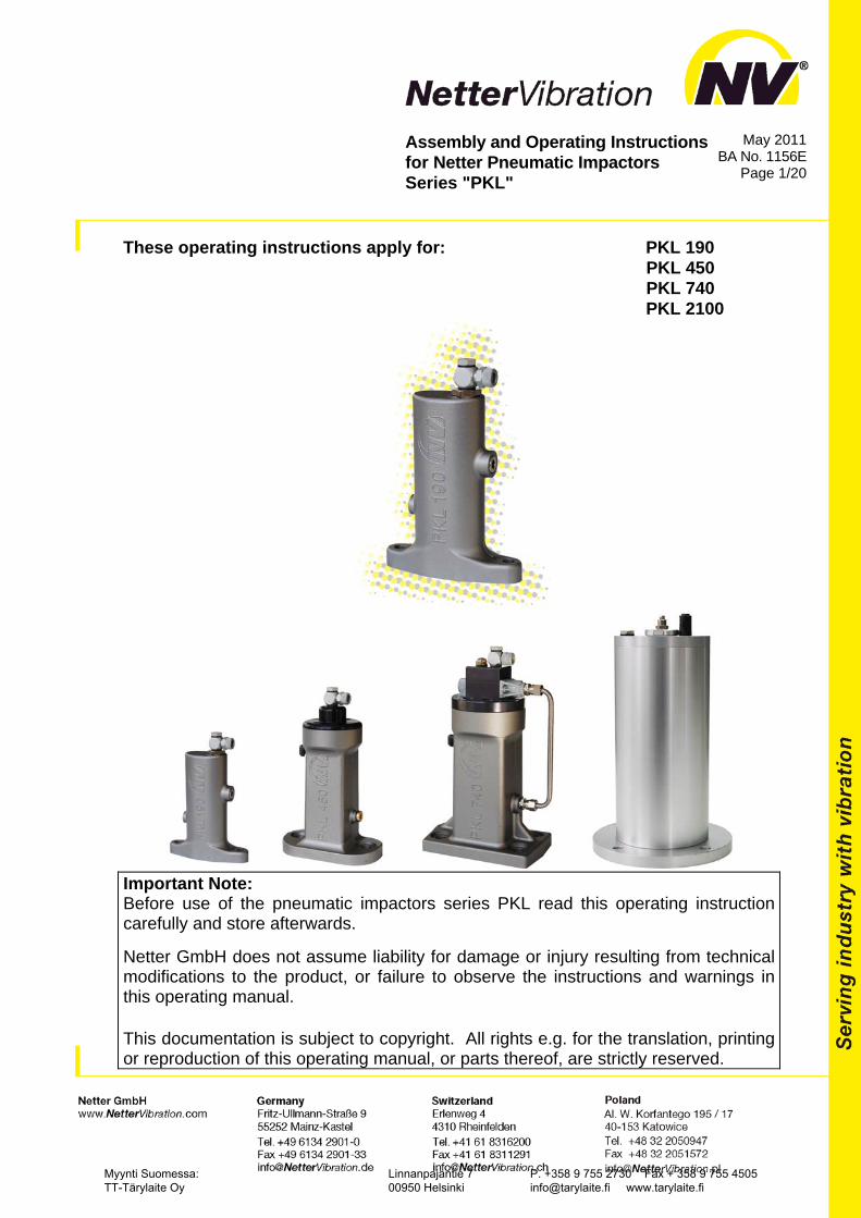
These operating instructions apply for: PKL 190
PKL 450 PKL 740
PKL 2100
Important Note: Before use of the pneumatic impactors series PKL read this operating instruction carefully and store afterwards. Netter GmbH does not assume liability for damage or injury resulting from technical modifications to the product, or failure to observe the instructions and warnings in this operating manual.
This documentation is subject to copyright. All rights e.g. for the translation, printing or reproduction of this operating manual, or parts thereof, are strictly reserved.
Myynti Suomessa: TT-Tärylaite Oy
Linnanpajantie 7 00950 Helsinki
P. +358 9 755 2730 Fax + 358 9 755 4505 [email protected] www.tarylaite.fi
2
Contents
1 GENERAL NOTES 3
2 TECHNICAL DATA 3
3 DESIGN AND FUNCTION 6
4 SAFETY 8
5 TRANSPORT AND STORAGE 10
6 INSTALLATION 10
7 START-UP / OPERATION 17
8 SERVICE / MAINTENANCE 18
9 TROUBLESHOOTING 19
10 SPARE PARTS 19
11 APPENDIX 20
11.1 Accessories 20
11.2 Displosal 20
11.3 Enclosures 20
Scope of delivery
Check the packing for possible signs of transport damage. In the event of damage to the packaging, check that the contents are com-plete and undamaged. If there is any damage, inform the shipping agent. Compare the scope of the delivery with the delivery note.
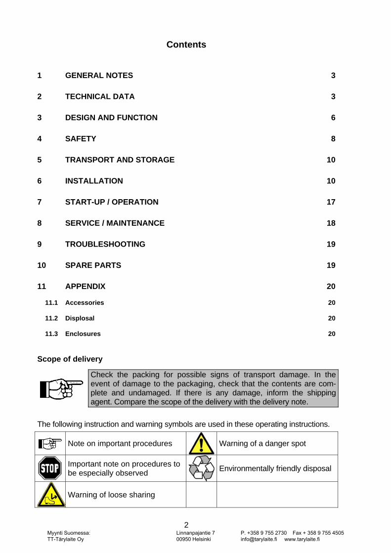
The following instruction and warning symbols are used in these operating instructions.
Note on important procedures Warning of a danger spot
Important note on procedures to be especially observed Environmentally friendly disposal
Warning of loose sharing
Myynti Suomessa: TT-Tärylaite Oy
Linnanpajantie 7 00950 Helsinki
P. +358 9 755 2730 Fax + 358 9 755 4505 [email protected] www.tarylaite.fi
3
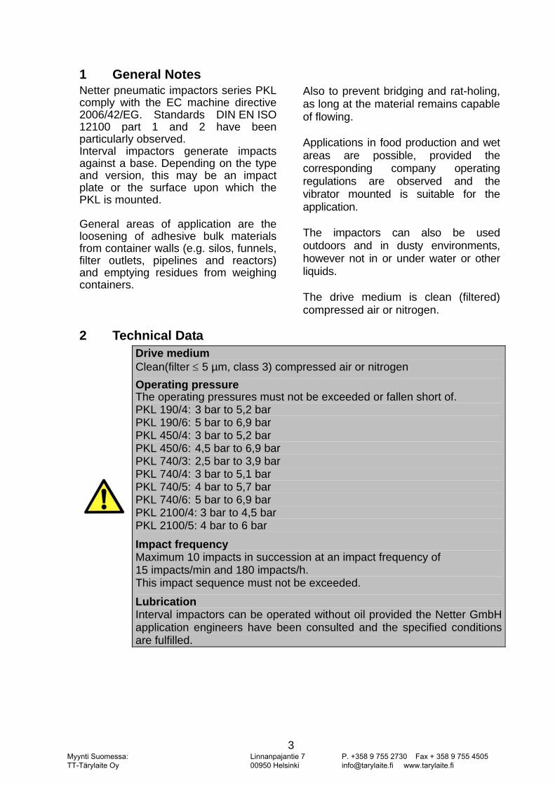
1 General Notes Netter pneumatic impactors series PKL comply with the EC machine directive 2006/42/EG. Standards DIN EN ISO 12100 part 1 and 2 have been particularly observed. Interval impactors generate impacts against a base. Depending on the type and version, this may be an impact plate or the surface upon which the PKL is mounted. General areas of application are the loosening of adhesive bulk materials from container walls (e.g. silos, funnels, filter outlets, pipelines and reactors) and emptying residues from weighing containers.
Also to prevent bridging and rat-holing, as long at the material remains capable of flowing. Applications in food production and wet areas are possible, provided the corresponding company operating regulations are observed and the vibrator mounted is suitable for the application. The impactors can also be used outdoors and in dusty environments, however not in or under water or other liquids. The drive medium is clean (filtered) compressed air or nitrogen.
2 Technical Data
Drive medium Clean(filter ≤ 5 µm, class 3) compressed air or nitrogen Operating pressure The operating pressures must not be exceeded or fallen short of. PKL 190/4: 3 bar to 5,2 bar PKL 190/6: 5 bar to 6,9 bar PKL 450/4: 3 bar to 5,2 bar PKL 450/6: 4,5 bar to 6,9 bar PKL 740/3: 2,5 bar to 3,9 bar PKL 740/4: 3 bar to 5,1 bar PKL 740/5: 4 bar to 5,7 bar PKL 740/6: 5 bar to 6,9 bar PKL 2100/4: 3 bar to 4,5 bar PKL 2100/5: 4 bar to 6 bar
Impact frequency Maximum 10 impacts in succession at an impact frequency of 15 impacts/min and 180 impacts/h. This impact sequence must not be exceeded.
Lubrication Interval impactors can be operated without oil provided the Netter GmbH application engineers have been consulted and the specified conditions are fulfilled.
Myynti Suomessa: TT-Tärylaite Oy
Linnanpajantie 7 00950 Helsinki
P. +358 9 755 2730 Fax + 358 9 755 4505 [email protected] www.tarylaite.fi
4
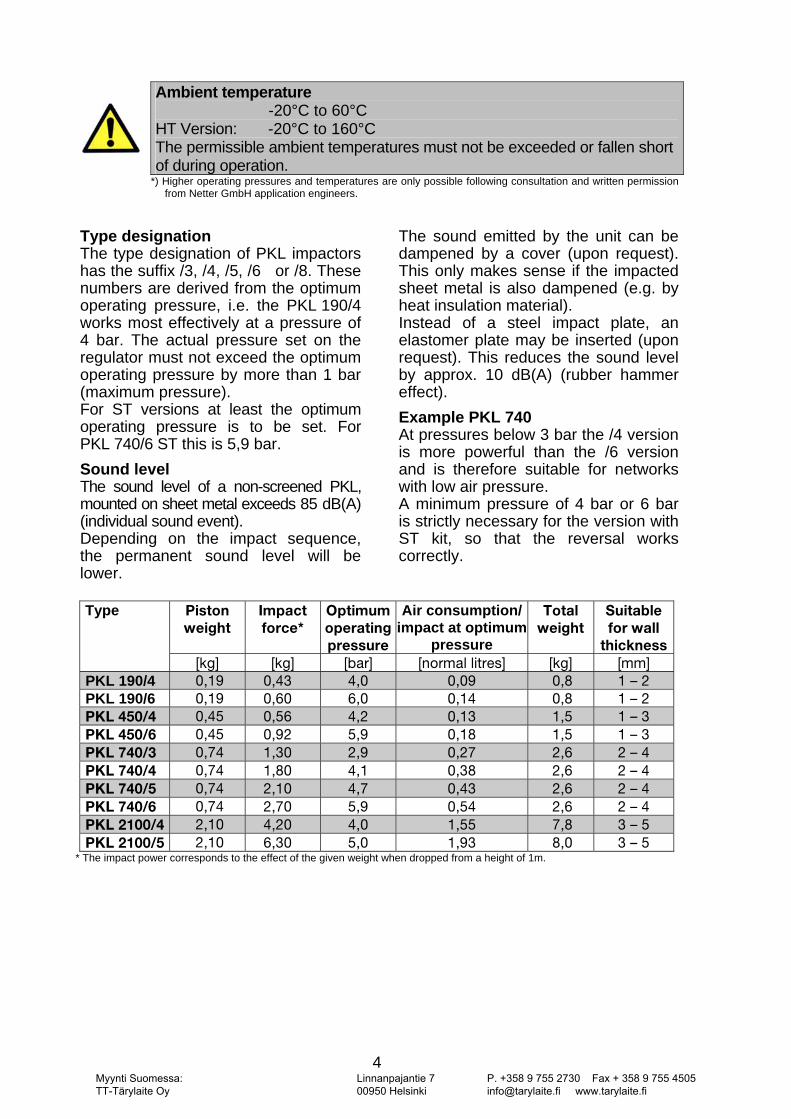
Ambient temperature -20°C to 60°C HT Version: -20°C to 160°C The permissible ambient temperatures must not be exceeded or fallen short of during operation.
*) Higher operating pressures and temperatures are only possible following consultation and written permission from Netter GmbH application engineers.
Type designation The type designation of PKL impactors has the suffix /3, /4, /5, /6 or /8. These numbers are derived from the optimum operating pressure, i.e. the PKL 190/4 works most effectively at a pressure of 4 bar. The actual pressure set on the regulator must not exceed the optimum operating pressure by more than 1 bar (maximum pressure). For ST versions at least the optimum operating pressure is to be set. For PKL 740/6 ST this is 5,9 bar. Sound level The sound level of a non-screened PKL, mounted on sheet metal exceeds 85 dB(A) (individual sound event). Depending on the impact sequence, the permanent sound level will be lower.
The sound emitted by the unit can be dampened by a cover (upon request). This only makes sense if the impacted sheet metal is also dampened (e.g. by heat insulation material). Instead of a steel impact plate, an elastomer plate may be inserted (upon request). This reduces the sound level by approx. 10 dB(A) (rubber hammer effect). Example PKL 740 At pressures below 3 bar the /4 version is more powerful than the /6 version and is therefore suitable for networks with low air pressure. A minimum pressure of 4 bar or 6 bar is strictly necessary for the version with ST kit, so that the reversal works correctly.
Type máëíçå=
ïÉáÖÜí=fãé~Åí=ÑçêÅÉG=
léíáãìã=çéÉê~íáåÖ=éêÉëëìêÉ
Air consumption/impact at optimum
pressure=
qçí~ä=ïÉáÖÜí=
=
pìáí~ÄäÉ=Ñçê=ï~ää=íÜáÅâåÉëë
xâÖz= xâÖz= xÄ~êz= xåçêã~ä=äáíêÉëz= xâÖz= xããz=PKL 190/4 MINV= MIQP= QIM= MIMV= MIU= N=Ó=O=PKL 190/6 MINV= MISM= SIM= MINQ= MIU= N=Ó=O=mhi=QRMLQ= MIQR= MIRS= QIO= MINP= NIR= N=Ó=P=mhi=QRMLS= MIQR= MIVO= RIV= MINU= NIR= N=Ó=P=mhi=TQMLP= MITQ= NIPM= OIV= MIOT= OIS= O=Ó=Q=mhi=TQMLQ= MITQ= NIUM= QIN= MIPU= OIS= O=Ó=Q=mhi=TQMLR= MITQ= OINM= QIT= MIQP= OIS= O=Ó=Q=mhi=TQMLS= MITQ= OITM= RIV= MIRQ= OIS= O=Ó=Q=mhi=ONMMLQ= OINM= QIOM= QIM= NIRR= TIU= P=Ó=R=mhi=ONMMLR= OINM= SIPM= RIM= NIVP= UIM= P=Ó=R=
* The impact power corresponds to the effect of the given weight when dropped from a height of 1m.
Myynti Suomessa: TT-Tärylaite Oy
Linnanpajantie 7 00950 Helsinki
P. +358 9 755 2730 Fax + 358 9 755 4505 [email protected] www.tarylaite.fi
5
PKL interval impactors can be used in dusty environments.
Interval impactors can be operated without oil provided the Netter GmbH application engineers have been con-sulted and the specified conditions are fulfilled.
Please note when planning: All PKL types must be operated with a 3/2-way valve. For automatic operation an optional control unit is required, e.g. Netter electronic timer AP 115. Exception: PKL with ST kit (automatic control). In this case the control works automatically. The impact sequence can be regulated by using an additional throttle.
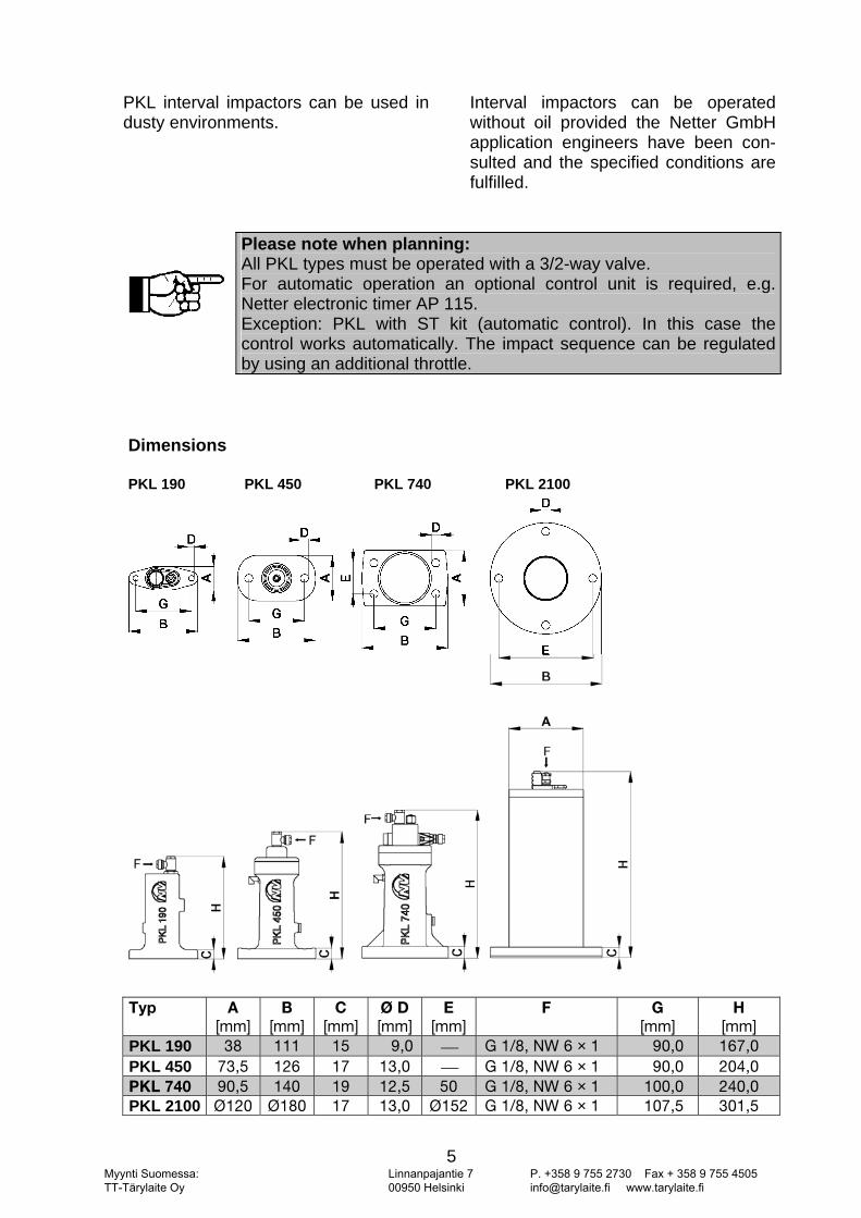
Dimensions PKL 190 PKL 450 PKL 740 PKL 2100
qóé= ^=
xããz=_=
xããz=`=
xããz=Õ=a=xããz=
b=xããz=
c==
d=xããz=
e=xããz=
PKL 190 PU= NNN= NR= VIM ⎯= d=NLUI=kt=S=×=N= VMIM= NSTIM=PKL 450 TPIR= NOS= NT= NPIM= ⎯= d=NLUI=kt=S=×=N= VMIM= OMQIM=mhi=TQM= VMIR= NQM= NV= NOIR= RM= d=NLUI=kt=S=×=N= NMMIM= OQMIM=PKL 2100 ÕNOM= ÕNUM= NT= NPIM= ÕNRO d=NLUI=kt=S=×=N= NMTIR= PMNIR=
Myynti Suomessa: TT-Tärylaite Oy
Linnanpajantie 7 00950 Helsinki
P. +358 9 755 2730 Fax + 358 9 755 4505 [email protected] www.tarylaite.fi
6
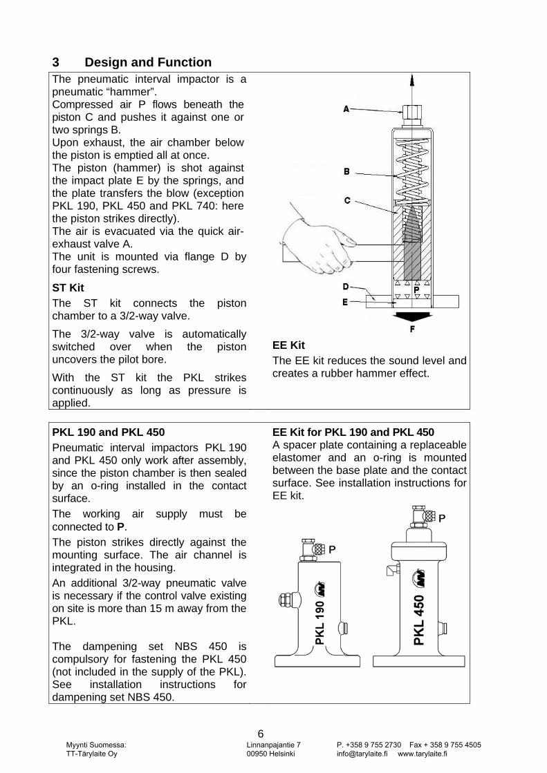
3 Design and Function The pneumatic interval impactor is a pneumatic “hammer”. Compressed air P flows beneath the piston C and pushes it against one or two springs B. Upon exhaust, the air chamber below the piston is emptied all at once. The piston (hammer) is shot against the impact plate E by the springs, and the plate transfers the blow (exception PKL 190, PKL 450 and PKL 740: here the piston strikes directly). The air is evacuated via the quick air-exhaust valve A. The unit is mounted via flange D by four fastening screws.
ST Kit The ST kit connects the piston chamber to a 3/2-way valve. The 3/2-way valve is automatically switched over when the piston uncovers the pilot bore. With the ST kit the PKL strikes continuously as long as pressure is applied.
EE Kit The EE kit reduces the sound level and creates a rubber hammer effect.
PKL 190 and PKL 450 Pneumatic interval impactors PKL 190 and PKL 450 only work after assembly, since the piston chamber is then sealed by an o-ring installed in the contact surface. The working air supply must be connected to P. The piston strikes directly against the mounting surface. The air channel is integrated in the housing. An additional 3/2-way pneumatic valve is necessary if the control valve existing on site is more than 15 m away from the PKL. The dampening set NBS 450 is compulsory for fastening the PKL 450 (not included in the supply of the PKL). See installation instructions for dampening set NBS 450.
EE Kit for PKL 190 and PKL 450 A spacer plate containing a replaceable elastomer and an o-ring is mounted between the base plate and the contact surface. See installation instructions for EE kit.
Myynti Suomessa: TT-Tärylaite Oy
Linnanpajantie 7 00950 Helsinki
P. +358 9 755 2730 Fax + 358 9 755 4505 [email protected] www.tarylaite.fi
7
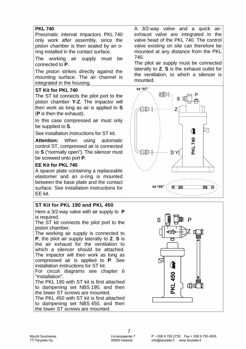
PKL 740 Pneumatic interval impactors PKL 740 only work after assembly, since the piston chamber is then sealed by an o-ring installed in the contact surface. The working air supply must be connected to P. The piston strikes directly against the mounting surface. The air channel is integrated in the housing.
A 3/2-way valve and a quick air-exhaust valve are integrated in the valve head of the PKL 740. The control valve existing on site can therefore be mounted at any distance from the PKL 740. The pilot air supply must be connected laterally to Z. S is the exhaust outlet for the ventilation, to which a silencer is mounted.
ST Kit for PKL 740 The ST kit connects the pilot port to the piston chamber Y-Z. The impactor will then work as long as air is applied to S (P is then the exhaust). In this case compressed air must only be supplied to S. See installation instructions for ST kit. Attention: When using automatic control ST, compressed air is connected to S (“normally open”). The silencer must be screwed onto port P. EE Kit for PKL 740 A spacer plate containing a replaceable elastomer and an o-ring is mounted between the base plate and the contact surface. See installation instructions for EE kit.
ST Kit for PKL 190 and PKL 450 Here a 3/2-way valve with air supply to P is required. The ST kit connects the pilot port to the piston chamber. The working air supply is connected to P, the pilot air supply laterally to Z. S is the air exhaust for the ventilation to which a silencer should be attached. The impactor will then work as long as compressed air is applied to P. See installation instructions for ST kit. For circuit diagrams see chapter 6 “Installation”. The PKL 190 with ST kit is first attached to dampening set NBS 190, and then the lower ST screws are mounted. The PKL 450 with ST kit is first attached to dampening set NBS 450, and then the lower ST screws are mounted.
Myynti Suomessa: TT-Tärylaite Oy
Linnanpajantie 7 00950 Helsinki
P. +358 9 755 2730 Fax + 358 9 755 4505 [email protected] www.tarylaite.fi
8
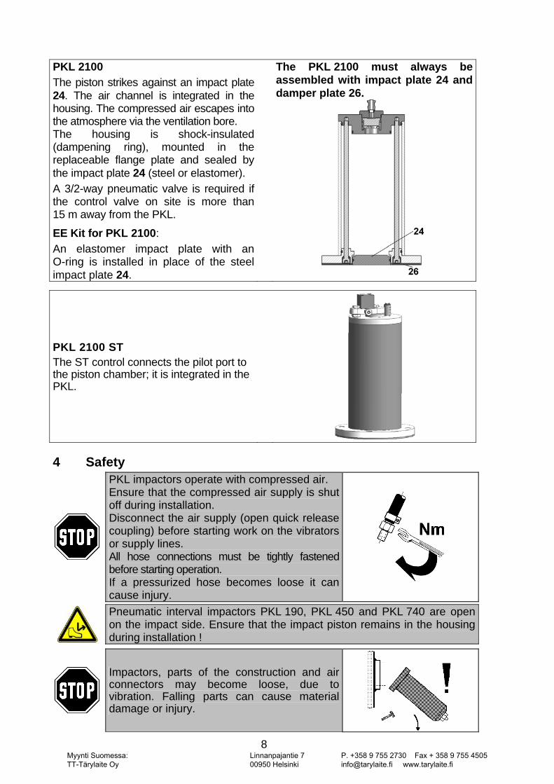
PKL 2100 The piston strikes against an impact plate 24. The air channel is integrated in the housing. The compressed air escapes into the atmosphere via the ventilation bore. The housing is shock-insulated (dampening ring), mounted in the replaceable flange plate and sealed by the impact plate 24 (steel or elastomer). A 3/2-way pneumatic valve is required if the control valve on site is more than 15 m away from the PKL.
EE Kit for PKL 2100: An elastomer impact plate with an O-ring is installed in place of the steel impact plate 24.
The PKL 2100 must always be assembled with impact plate 24 and damper plate 26.
PKL 2100 ST The ST control connects the pilot port to the piston chamber; it is integrated in the PKL.
4 Safety
PKL impactors operate with compressed air. Ensure that the compressed air supply is shut off during installation. Disconnect the air supply (open quick release coupling) before starting work on the vibrators or supply lines. All hose connections must be tightly fastened before starting operation. If a pressurized hose becomes loose it can cause injury.
Pneumatic interval impactors PKL 190, PKL 450 and PKL 740 are open on the impact side. Ensure that the impact piston remains in the housing during installation !
Impactors, parts of the construction and air connectors may become loose, due to vibration. Falling parts can cause material damage or injury.
Myynti Suomessa: TT-Tärylaite Oy
Linnanpajantie 7 00950 Helsinki
P. +358 9 755 2730 Fax + 358 9 755 4505 [email protected] www.tarylaite.fi
9
Screw retention devices and / or Loctite or similar are to be used. Screwed connections and air connectors should be checked after 1 hour of operation and then at regular intervals (generally once per month) and tightened, if necessary. Netter fastening set NBS is recommended for the attachment of impactors PKL 190, PKL 740 and PKL 2100. Interval impactors PKL 450 will be installed with a dampening set; PKL 2100 with a damper plate.In critical installation situations, it is possible to secure the vibrator with a clamp and steel rope.
In the vicinity of the impactor, or structures connected to the impactor, the sound level can exceed 85 dB(A). When working in the noise area, ear defenders are required if the sound level exceeds 85 dB(A).
Drive medium
Clean (filter ≤ 5 µm, class 3) compressed air or nitrogen Operating pressure The operating pressures must not be exceeded or fallen short of PKL 190/4: 3 bar to 5,2 bar PKL 190/6: 5 bar to 6,9 bar PKL 450/4: 3 bar to 5,2 bar PKL 450/6: 4,5 bar to 6,9 bar PKL 740/3: 2,5 bar to 3,9 bar PKL 740/4: 3 bar to 5,1 bar PKL 740/5: 4 bar to 5,7 bar PKL 740/6: 5 bar to 6,9 bar PKL 2100/4: 3 bar to 4,5 bar PKL 2100/5: 4 bar to 6 bar Lubrication Interval impactors can be operated without oil provided the Netter GmbH application engineers have been consulted and the specified conditions are fulfilled.
Impact frequency Maximum 10 impacts in succession at an impact frequency of 15 impacts/min and 180 impacts/h. This impact sequence must not be exceeded. Ambient temperature -20°C to 60°C HT versions: -20°C to160°C The permissible ambient temperatures must not be exceeded or fallen short of during operation.
*) Higher operating pressures and temperatures are only possible following consultation and written permission from Netter GmbH application engineers.
Modifications Modifications to the unit can alter the characteristics of the interval impactors or destroy the unit, and result in the rejection of all warranty claims.
Myynti Suomessa: TT-Tärylaite Oy
Linnanpajantie 7 00950 Helsinki
P. +358 9 755 2730 Fax + 358 9 755 4505 [email protected] www.tarylaite.fi
10
5 Transport and Storage
Check the packaging for possible signs of transport damage. In the event of damage to the packaging, check that the contents are com-plete and undamaged. If there is any damage, inform the shipping agent.
The units are packed ready-to-install. The type label is attached to the impactor. Accessories and add-on parts are delivered unmounted, unless otherwise agreed. Special transport conditions are not stipulated. The units should be stored in a clean, dry environment. PKL pneumatic interval impactors must be oiled before going back into storage (pour machine oil into air inlet port and activate briefly).
PKL 190, PKL 450 and PKL 740 must be screwed or clamped to a plate before operation. The impact plate must be inserted. Use ear protections. The storage temperature should be between -40 and +60°C. This does not apply to the operating temperature; compare with chapter 4 SAFETY “Permissible Operating Conditions”.
6 Installation
Ensure that the compressed air supply is shut off during installation or when working on the impactor and air supply lines.
Pneumatic interval impactors PKL 190, PKL 450 and PKL 740 are open on the impact side. Ensure that the impact piston remains in the housing during installation!
Mounting the impactor
Series PKL 450 impactors must always be installed with damper kit NBS 450, according to the installation instructions! This damper kit is not included in the scope of delivery.
PKL impactors are screwed to level reinforcement sections or weld-on consoles (œ0.3mm flatness). Suitable weld-on consoles are available from kÉííÉêVibration (see appendix). Please note that series PKL 190, PKL 450 and PKL 740 impactors are open at the bottom and can only work once they have been mounted to a plane surface.
Myynti Suomessa: TT-Tärylaite Oy
Linnanpajantie 7 00950 Helsinki
P. +358 9 755 2730 Fax + 358 9 755 4505 [email protected] www.tarylaite.fi
11
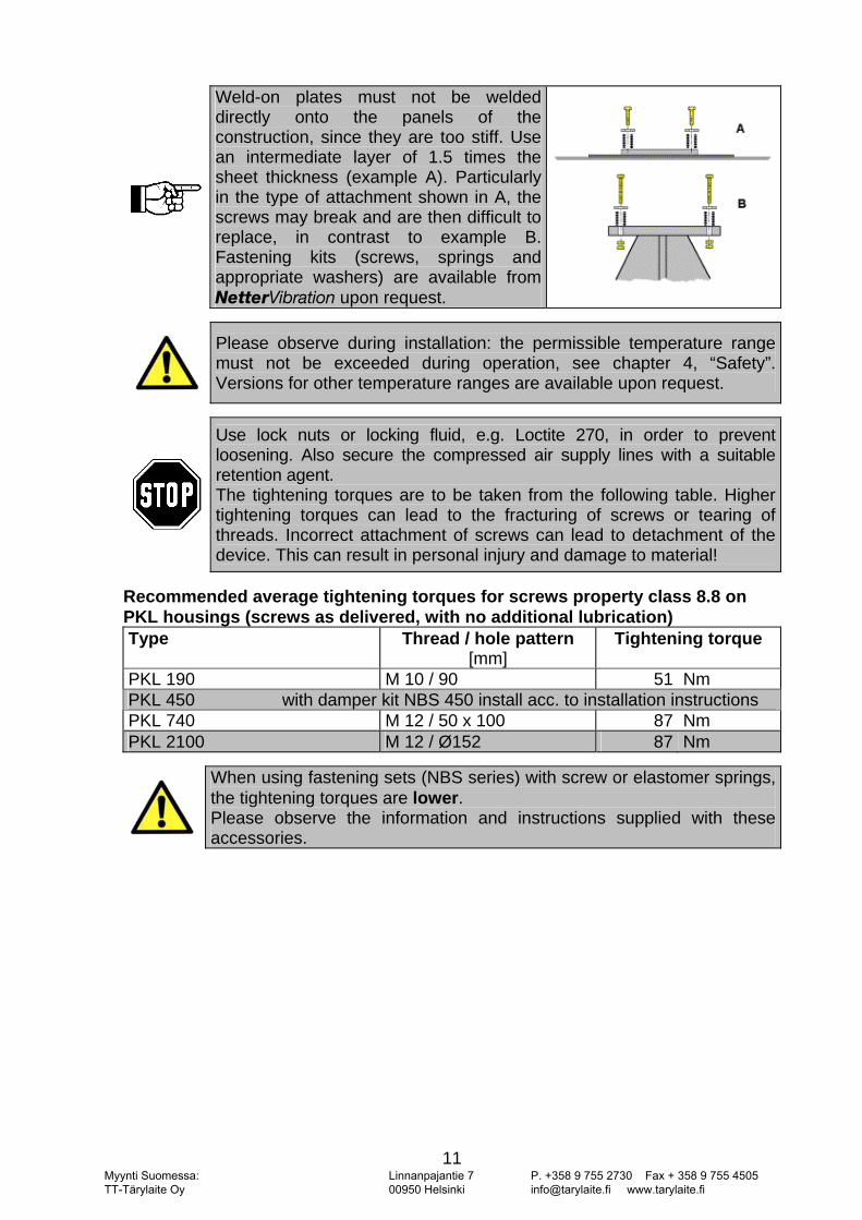
Weld-on plates must not be welded directly onto the panels of the construction, since they are too stiff. Use an intermediate layer of 1.5 times the sheet thickness (example A). Particularly in the type of attachment shown in A, the screws may break and are then difficult to replace, in contrast to example B. Fastening kits (screws, springs and appropriate washers) are available from kÉííÉêVibration upon request.
Please observe during installation: the permissible temperature range must not be exceeded during operation, see chapter 4, “Safety”. Versions for other temperature ranges are available upon request.
Use lock nuts or locking fluid, e.g. Loctite 270, in order to prevent loosening. Also secure the compressed air supply lines with a suitable retention agent. The tightening torques are to be taken from the following table. Higher tightening torques can lead to the fracturing of screws or tearing of threads. Incorrect attachment of screws can lead to detachment of the device. This can result in personal injury and damage to material!
Recommended average tightening torques for screws property class 8.8 on PKL housings (screws as delivered, with no additional lubrication) Type Thread / hole pattern
[mm] Tightening torque
PKL 190 M 10 / 90 51 Nm PKL 450 with damper kit NBS 450 install acc. to installation instructions PKL 740 M 12 / 50 x 100 87 Nm PKL 2100 M 12 / Ø152 87 Nm
When using fastening sets (NBS series) with screw or elastomer springs, the tightening torques are lower. Please observe the information and instructions supplied with these accessories.
Myynti Suomessa: TT-Tärylaite Oy
Linnanpajantie 7 00950 Helsinki
P. +358 9 755 2730 Fax + 358 9 755 4505 [email protected] www.tarylaite.fi
12
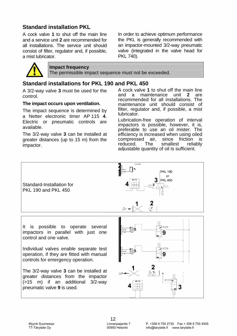
Standard installation PKL A cock valve 1 to shut off the main line and a service unit 2 are recommended for all installations. The service unit should consist of filter, regulator and, if possible, a mist lubricator.
In order to achieve optimum performance the PKL is generally recommended with an impactor-mounted 3/2-way pneumatic valve (integrated in the valve head for PKL 740).
Impact frequency The permissible impact sequence must not be exceeded.
Standard installations for PKL 190 and PKL 450 A 3/2-way valve 3 must be used for the control. The impact occurs upon ventilation. The impact sequence is determined by a Netter electronic timer AP 115 4. Electric or pneumatic controls are available. The 3/2-way valve 3 can be installed at greater distances (up to 15 m) from the impactor.
A cock valve 1 to shut off the main line and a maintenance unit 2 are recommended for all installations. The maintenance unit should consist of filter, regulator and, if possible, a mist lubricator. Lubrication-free operation of interval impactors is possible, however, it is, preferable to use an oil mister. The efficiency is increased when using oiled compressed air, since friction is reduced. The smallest reliably adjustable quantity of oil is sufficient.
Standard-Installation for PKL 190 and PKL 450
It is possible to operate several impactors in parallel with just one control and one valve. Individual valves enable separate test operation, if they are fitted with manual controls for emergency operation. The 3/2-way valve 3 can be installed at greater distances from the impactor (>15 m) if an additional 3/2-way pneumatic valve 9 is used.
Myynti Suomessa: TT-Tärylaite Oy
Linnanpajantie 7 00950 Helsinki
P. +358 9 755 2730 Fax + 358 9 755 4505 [email protected] www.tarylaite.fi
13
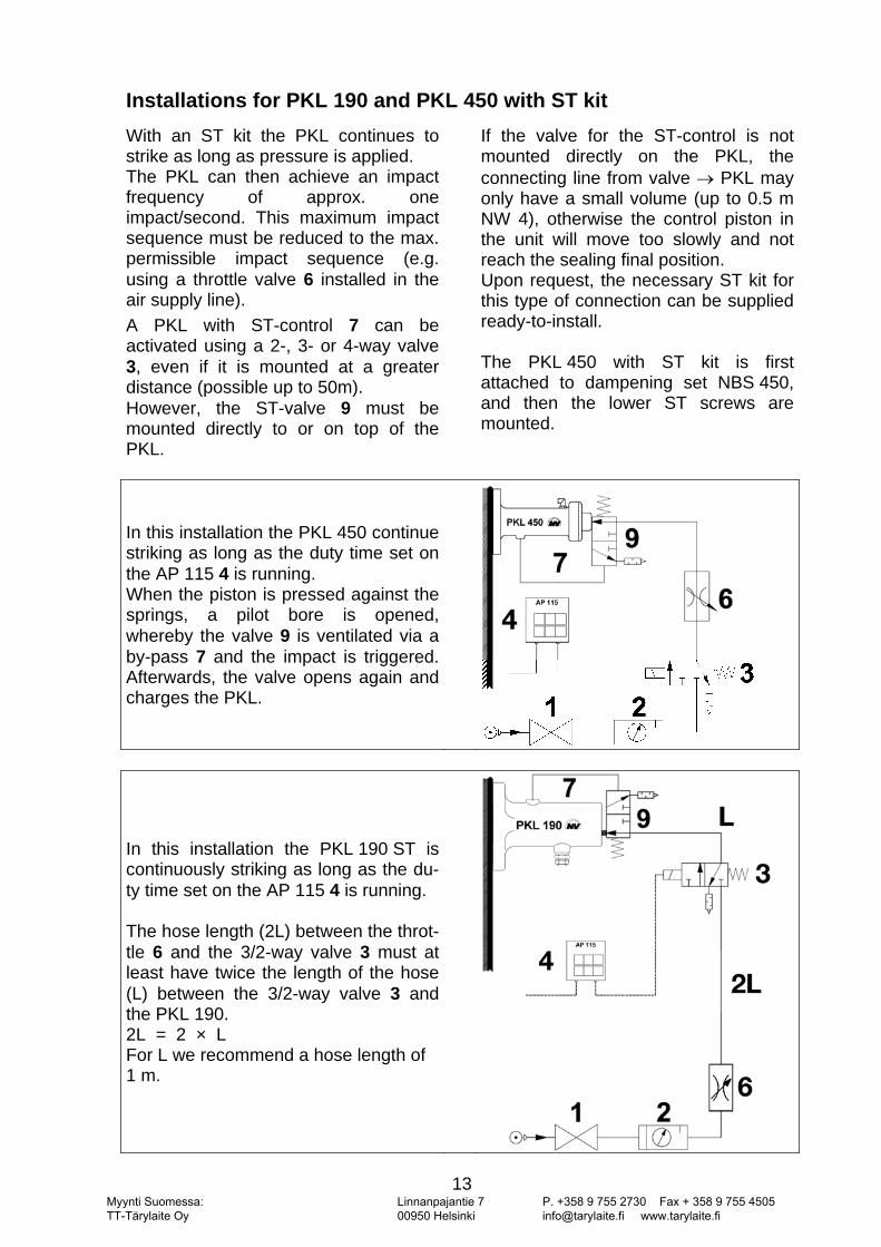
Installations for PKL 190 and PKL 450 with ST kit With an ST kit the PKL continues to strike as long as pressure is applied. The PKL can then achieve an impact frequency of approx. one impact/second. This maximum impact sequence must be reduced to the max. permissible impact sequence (e.g. using a throttle valve 6 installed in the air supply line). A PKL with ST-control 7 can be activated using a 2-, 3- or 4-way valve 3, even if it is mounted at a greater distance (possible up to 50m). However, the ST-valve 9 must be mounted directly to or on top of the PKL.
If the valve for the ST-control is not mounted directly on the PKL, the connecting line from valve → PKL may only have a small volume (up to 0.5 m NW 4), otherwise the control piston in the unit will move too slowly and not reach the sealing final position. Upon request, the necessary ST kit for this type of connection can be supplied ready-to-install. The PKL 450 with ST kit is first attached to dampening set NBS 450, and then the lower ST screws are mounted.
In this installation the PKL 450 continue striking as long as the duty time set on the AP 115 4 is running. When the piston is pressed against the springs, a pilot bore is opened, whereby the valve 9 is ventilated via a by-pass 7 and the impact is triggered. Afterwards, the valve opens again and charges the PKL.
In this installation the PKL 190 ST is continuously striking as long as the du-ty time set on the AP 115 4 is running. The hose length (2L) between the throt-tle 6 and the 3/2-way valve 3 must at least have twice the length of the hose (L) between the 3/2-way valve 3 and the PKL 190. 2L = 2 × L For L we recommend a hose length of 1 m.
Myynti Suomessa: TT-Tärylaite Oy
Linnanpajantie 7 00950 Helsinki
P. +358 9 755 2730 Fax + 358 9 755 4505 [email protected] www.tarylaite.fi
14
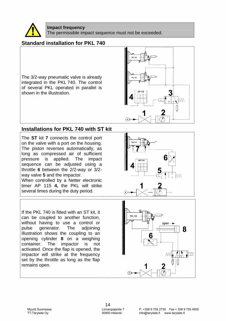
Impact frequency The permissible impact sequence must not be exceeded.
Standard installation for PKL 740
The 3/2-way pneumatic valve is already integrated in the PKL 740. The control of several PKL operated in parallel is shown in the illustration.
Installations for PKL 740 with ST kit
The ST kit 7 connects the control port on the valve with a port on the housing. The piston reverses automatically, as long as compressed air of sufficient pressure is applied. The impact sequence can be adjusted using a throttle 6 between the 2/2-way or 3/2-way valve 5 and the impactor. When controlled by a Netter electronic timer AP 115 4, the PKL will strike several times during the duty period.
If the PKL 740 is fitted with an ST kit, it can be coupled to another function, without having to use a control or pulse generator. The adjoining illustration shows the coupling to an opening cylinder 8 on a weighing container. The impactor is not activated. Once the flap is opened, the impactor will strike at the frequency set by the throttle as long as the flap remains open.
Myynti Suomessa: TT-Tärylaite Oy
Linnanpajantie 7 00950 Helsinki
P. +358 9 755 2730 Fax + 358 9 755 4505 [email protected] www.tarylaite.fi
15
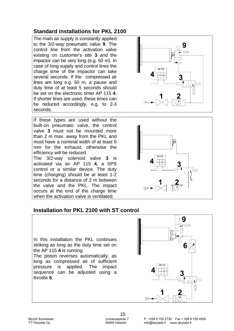
Standard installations for PKL 2100 The main air supply is constantly applied to the 3/2-way pneumatic valve 9. The control line from the activation valve existing on customer’s site 3 and the impactor can be very long (e.g. 50 m). In case of long supply and control lines the charge time of the impactor can take several seconds. If the compressed air lines are long e.g. 50 m, a pause and duty time of at least 5 seconds should be set on the electronic timer AP 115 4. If shorter lines are used, these times can be reduced accordingly, e.g. to 2-3 seconds.
If these types are used without the built-on pneumatic valve, the control valve 3 must not be mounted more than 2 m max. away from the PKL and must have a nominal width of at least 6 mm for the exhaust, otherwise the efficiency will be reduced. The 3/2-way solenoid valve 3 is activated via an AP 115 4, a SPS control or a similar device. The duty time (charging) should be at least 1-2 seconds for a distance of 2 m between the valve and the PKL. The impact occurs at the end of the charge time when the activation valve is ventilated.
Installation for PKL 2100 with ST control
In this installation the PKL continues striking as long as the duty time set on the AP 115 4 is running. The piston reverses automatically, as long as compressed air of sufficient pressure is applied. The impact sequence can be adjusted using a throttle 6.
Myynti Suomessa: TT-Tärylaite Oy
Linnanpajantie 7 00950 Helsinki
P. +358 9 755 2730 Fax + 358 9 755 4505 [email protected] www.tarylaite.fi
16
Recommended cross-sections for valves and hoses PKL 190: Control lines, control valves: NW 6 × 1 Main air supply: NW 6 × 1 PKL 450: Control lines, control valves: NW 6 × 1 Main air supply: NW 6 × 1 PKL 740: Control lines, control valves: NW 6 × 1 Main air supply: NW 6 × 1 PKL 2100: Control lines, control valves: NW 6 × 1 Main air supply: NW 6 × 1
Use NW 6 (max 15 m) for connection of the control valve to PKL 190 and PKL 450. For the activation of several PKL 190 or PKL 450 the total length must not exceed 50 m (see illustrations on page 14).
Checklist for installation: 1) 2) 3) 4) 5) 6) 7)
Consider expected operational temperature. Install PKL 450 with dampening set. Secure fastening screws. Install the service unit (filter, mist lubricator, regulator, as required), valve and supply line. Are fastening screws secured? Check! Are compressed air supply lines glued in? Check! Has the information on hose length and nominal width been observed?Is the unit secured from falling down?
Myynti Suomessa: TT-Tärylaite Oy
Linnanpajantie 7 00950 Helsinki
P. +358 9 755 2730 Fax + 358 9 755 4505 [email protected] www.tarylaite.fi
17
7 Start-Up / Operation
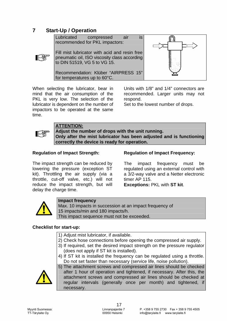
Lubricated compressed air is recommended for PKL impactors:
Fill mist lubricator with acid and resin free pneumatic oil, ISO viscosity class according to DIN 51519, VG 5 to VG 15.
Recommendation: Klüber “AIRPRESS 15”for temperatures up to 60°C.
When selecting the lubricator, bear in mind that the air consumption of the PKL is very low. The selection of the lubricator is dependent on the number of impactors to be operated at the same time.
Units with 1/8” and 1/4” connectors are recommended. Larger units may not respond. Set to the lowest number of drops.
ATTENTION: Adjust the number of drops with the unit running. Only after the mist lubricator has been adjusted and is functioning correctly the device is ready for operation.
Regulation of Impact Strength: The impact strength can be reduced by lowering the pressure (exception ST kit). Throttling the air supply (via a throttle, cut-off valve, etc.) will not reduce the impact strength, but will delay the charge time.
Regulation of Impact Frequency: The impact frequency must be regulated using an external control with a 3/2-way valve and a Netter electronic timer AP 115. Exceptions: PKL with ST kit.
Impact frequency Max. 10 impacts in succession at an impact frequency of 15 impacts/min and 180 impacts/h. This impact sequence must not be exceeded.
Checklist for start-up:
1) Adjust mist lubricator, if available. 2) Check hose connections before opening the compressed air supply. 3) If required, set the desired impact strength on the pressure regulator
(does not apply if ST kit is installed). 4) If ST kit is installed the frequency can be regulated using a throttle.
Do not set faster than necessary (service life, noise pollution).
5) The attachment screws and compressed air lines should be checked after 1 hour of operation and tightened, if necessary. After this, the attachment screws and compressed air lines should be checked at regular intervals (generally once per month) and tightened, if necessary.
Myynti Suomessa: TT-Tärylaite Oy
Linnanpajantie 7 00950 Helsinki
P. +358 9 755 2730 Fax + 358 9 755 4505 [email protected] www.tarylaite.fi
18
8 Service / Maintenance
Please observe the safety regulations in chapter 4 when servicing the device.
Before starting inspection or service work, shut off the compressed air supply and protect it against unintentional activation!
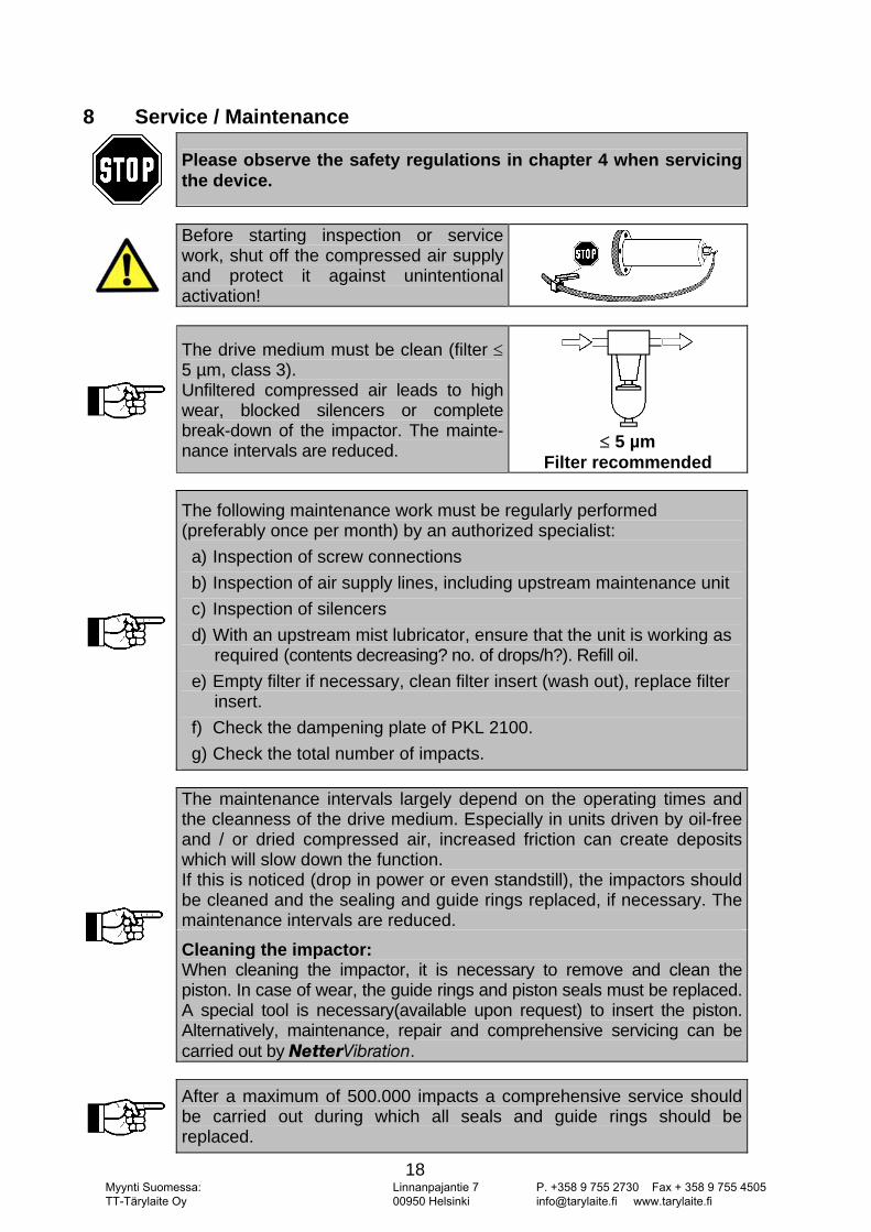
The drive medium must be clean (filter ≤5 µm, class 3). Unfiltered compressed air leads to high wear, blocked silencers or complete break-down of the impactor. The mainte-nance intervals are reduced.
≤ 5 µm
Filter recommended
The following maintenance work must be regularly performed (preferably once per month) by an authorized specialist:
a) Inspection of screw connections b) Inspection of air supply lines, including upstream maintenance unit c) Inspection of silencers d) With an upstream mist lubricator, ensure that the unit is working as
required (contents decreasing? no. of drops/h?). Refill oil. e) Empty filter if necessary, clean filter insert (wash out), replace filter
insert. f) Check the dampening plate of PKL 2100. g) Check the total number of impacts.
The maintenance intervals largely depend on the operating times and the cleanness of the drive medium. Especially in units driven by oil-free and / or dried compressed air, increased friction can create deposits which will slow down the function. If this is noticed (drop in power or even standstill), the impactors should be cleaned and the sealing and guide rings replaced, if necessary. The maintenance intervals are reduced.
Cleaning the impactor: When cleaning the impactor, it is necessary to remove and clean the piston. In case of wear, the guide rings and piston seals must be replaced. A special tool is necessary(available upon request) to insert the piston. Alternatively, maintenance, repair and comprehensive servicing can be carried out by kÉííÉêsáÄê~íáçå.
After a maximum of 500.000 impacts a comprehensive service should be carried out during which all seals and guide rings should be replaced.
Myynti Suomessa: TT-Tärylaite Oy
Linnanpajantie 7 00950 Helsinki
P. +358 9 755 2730 Fax + 358 9 755 4505 [email protected] www.tarylaite.fi
19
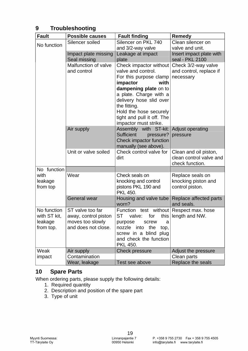
9 Troubleshooting Fault Possible causes Fault finding Remedy
No function Silencer soiled Silencer on PKL 740 and 3/2-way valve
Clean silencer on valve and unit.
Impact plate missingSeal missing
Leakage at impact plate
Insert impact plate with seal - PKL 2100
Malfunction of valve and control
Check impactor without valve and control. For this purpose clamp impactor with dampening plate on to a plate. Charge with a delivery hose slid over the fitting. Hold the hose securely tight and pull it off. The impactor must strike.
Check 3/2-way valve and control, replace if necessary
Air supply Assembly with ST-kit: Sufficient pressure? Check impactor function manually (see above).
Adjust operating pressure
Unit or valve soiled Check control valve for dirt
Clean and oil piston, clean control valve and check function.
No function with leakage from top
Wear Check seals on
knocking and control pistons PKL 190 and PKL 450.
Replace seals on knocking piston and control piston.
General wear Housing and valve tube worn?
Replace affected parts and seals.
No function with ST kit, leakage from top.
ST valve too far away, control piston moves too slowly and does not close.
Function test without ST valve: for this purpose screw a nozzle into the top, screw in a blind plug and check the functionPKL 450.
Respect max. hose length and NW.
Weak impact
Air supply Check pressure Adjust the pressure Contamination Clean parts Wear, leakage Test see above Replace the seals
10 Spare Parts When ordering parts, please supply the following details: 1. Required quantity 2. Description and position of the spare part 3. Type of unit
Myynti Suomessa: TT-Tärylaite Oy
Linnanpajantie 7 00950 Helsinki
P. +358 9 755 2730 Fax + 358 9 755 4505 [email protected] www.tarylaite.fi
20
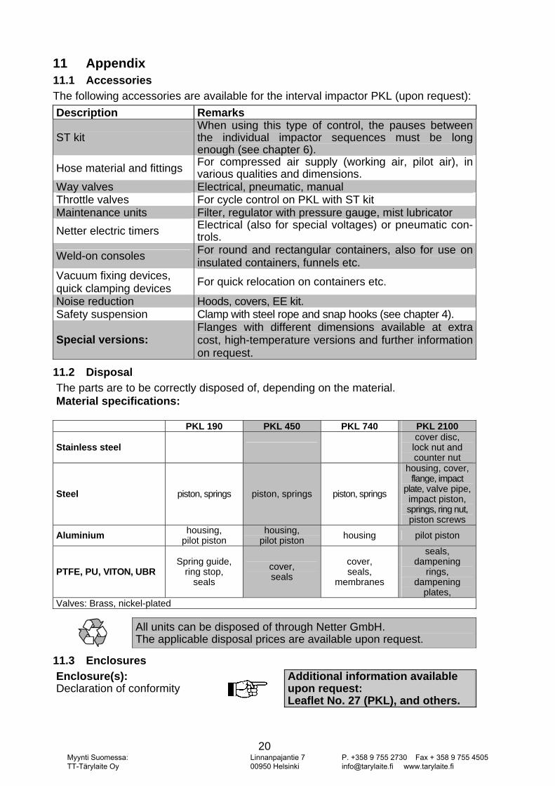
11 Appendix 11.1 Accessories The following accessories are available for the interval impactor PKL (upon request): Description Remarks
ST kit When using this type of control, the pauses between the individual impactor sequences must be long enough (see chapter 6).
Hose material and fittings For compressed air supply (working air, pilot air), in various qualities and dimensions.
Way valves Electrical, pneumatic, manual Throttle valves For cycle control on PKL with ST kit Maintenance units Filter, regulator with pressure gauge, mist lubricator Netter electric timers Electrical (also for special voltages) or pneumatic con-
trols.
Weld-on consoles For round and rectangular containers, also for use on insulated containers, funnels etc.
Vacuum fixing devices, quick clamping devices For quick relocation on containers etc.
Noise reduction Hoods, covers, EE kit. Safety suspension Clamp with steel rope and snap hooks (see chapter 4).
Special versions: Flanges with different dimensions available at extra cost, high-temperature versions and further information on request.
11.2 Disposal The parts are to be correctly disposed of, depending on the material. Material specifications:
PKL 190 PKL 450 PKL 740 PKL 2100
Stainless steel
cover disc,
lock nut and counter nut
Steel piston, springs piston, springs piston, springs
housing, cover, flange, impact
plate, valve pipe,impact piston, springs, ring nut, piston screws
Aluminium housing, pilot piston
housing,pilot piston housing pilot piston
PTFE, PU, VITON, UBR Spring guide,
ring stop, seals
cover, seals
cover, seals,
membranes
seals, dampening
rings, dampening
plates, Valves: Brass, nickel-plated
All units can be disposed of through Netter GmbH. The applicable disposal prices are available upon request.
11.3 Enclosures Enclosure(s): Declaration of conformity
Additional information available upon request: Leaflet No. 27 (PKL), and others.
Myynti Suomessa: TT-Tärylaite Oy
Linnanpajantie 7 00950 Helsinki
P. +358 9 755 2730 Fax + 358 9 755 4505 [email protected] www.tarylaite.fi