Embed Size (px)
Citation preview
P0050
9 Jan 1998
Assembly Procedure of Caging Units, SM
STANFORD UNIVERSITY
W.W. HANSEN EXPERIMENTAL PHYSICS LABORATORY
GRAVITY PROBE B, RELATIVITY GYROSCOPE EXPERIMENT
STANFORD, CALIFORNIA 94305-4085
ASSEMBLY AND
IN-PROCESS TESTS
OF SCIENCE MISSION
CAGING UNITS
GP-B SCIENCE MISSION PROCEDURE
9 January 1998
PREPARED
A. Nakashima, Systems
PREPARED
J. Stamets,REE Manufacture & Test
APPROVED
M. Sullivan, REE Design
APPROVED
J. Turneaure, Hardware Manager
APPROVED
B. Taller, QA
P0050
9 Jan 1998
Assembly Procedure of Caging Units, SM
ii
TABLE OF CONTENTS
1. SCOPE......................................................................................................................1
2. REFERENCES ..........................................................................................................2
3. GENERAL REQUIREMENTS ................................................................................2
3.1 Environmental Requirements...................................................................................................... 2
3.2 Personnel ...................................................................................................................................... 2
3.3 Safety............................................................................................................................................ 3
3.4. Quality Assurance....................................................................................................................... 3
3.5. Red-line Authority ...................................................................................................................... 3
4. REQUIRED EQUIPMENT.......................................................................................4
5. ASSEMBLY, WELD, AND TEST OF THE DIAPHRAGM SUBASSEMBLY,
P/N 22793-302 ..........................................................................................................6
5.1 Assembly and Weld of Diaphragm Subassembly (Weldments 1 - 5) .......................................... 6
5.2 LN2 Dip, Leak Test and Mag Test of Diaphragm Subassembly .............................................. 11
6. ASSEMBLY, BRAZE, AND TEST OF TUBING ASSEMBLY, CAGING, P/N
22822-201 ............................................................................................................... 12
6.1 Assembly and Braze of Tubing Assembly, Caging.................................................................... 12
6.2 LN2 Dip, Leak Test, Epoxy Bond, and Mag Test of Tubing Assembly.................................... 13
7. ASSEMBLY, WELD, AND TEST OF DIAPHRAGM ASSEMBLY, P/N 22793-
301 .......................................................................................................................... 15
7.1 Assembly and Weld of Diaphragm Assembly (Weldments 6 & 7)............................................ 15
7.2 Pressure Test of Diaphragm Assembly...................................................................................... 17
7.3 LN2 Dip of Serialized Units....................................................................................................... 21
7.4 Leak Test of Serialized Units..................................................................................................... 21
8. ASSEMBLY AND MEASUREMENTS OF ACTUATOR ASSEMBLY P/N
22794-301 ............................................................................................................... 25
8.1 Assembly of Actuator Assembly ................................................................................................ 25
8.2 Dimensional Measurements of Actuator Assembly................................................................... 26
9. MATCH MACHINING THE HOUSING (P/N 22802-101) AND ROD (P/N 22798-
101) TO THE ACTUATOR ASSEMBLY ............................................................ 29
9.1 Match Machining Housing and Rod to Actuator Assembly...................................................... 29
10. ASSEMBLY AND TEST OF HOUSING/ACTUATOR ASSEMBLY, P/N
22805-301 ............................................................................................................... 32
10.1 Assembly of Housing/Actuator Assembly ................................................................................ 32
10.2 Test and Measurement of Housing/Actuator Assembly .......................................................... 33
P0050
9 Jan 1998
Assembly Procedure of Caging Units, SM
iii
11. ASSEMBLY AND DIMENSIONAL MEASUREMENTS OF MECHANISM
ASSEMBLY, P/N 22809-301................................................................................. 38
11.1 Assembly of Mechanism Assembly .......................................................................................... 38
11.2 Dimensional Measurement and Magnetic Test of Mechanism Assembly............................... 38
12. ASSEMBLY OF CAGING SUBASSEMBLY, P/N 23190-301............................ 40
12.1 Assembly of Caging Subssembly.............................................................................................. 40
13. ASSEMBLY AND TEST OF TUBING ASSEMBLY, CAGING JUMPER LINE,
P/N 23188-201 ........................................................................................................ 41
13.1 Assembly of Tubing Assembly, Caging Jumper Line.............................................................. 41
13.2 LN2 Dip, Leak Test, and Mag Test of Tubing Assembly, Caging Jumper Line .................... 42
14. CAGING ASSEMBLY, P/N 23172-301 ................................................................ 43
15. PROCEDURE COMPLETION............................................................................ 44
16. DATA BASE ENTRY............................................................................................ 44
P0050
9 Jan 1998
Assembly Procedure of Caging Units, SM
1
1
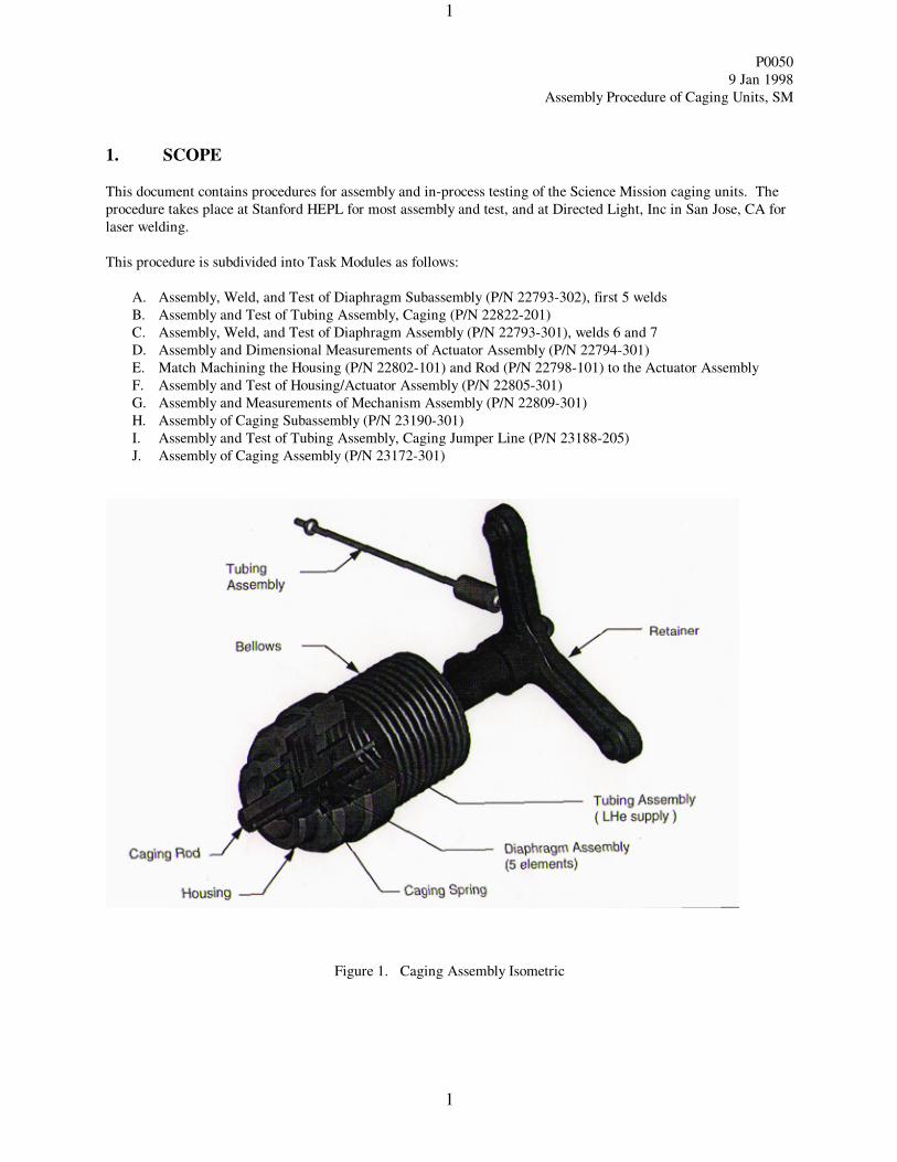
1. SCOPE
This document contains procedures for assembly and in-process testing of the Science Mission caging units. The
procedure takes place at Stanford HEPL for most assembly and test, and at Directed Light, Inc in San Jose, CA for
laser welding.
This procedure is subdivided into Task Modules as follows:
A. Assembly, Weld, and Test of Diaphragm Subassembly (P/N 22793-302), first 5 welds
B. Assembly and Test of Tubing Assembly, Caging (P/N 22822-201)
C. Assembly, Weld, and Test of Diaphragm Assembly (P/N 22793-301), welds 6 and 7
D. Assembly and Dimensional Measurements of Actuator Assembly (P/N 22794-301)
E. Match Machining the Housing (P/N 22802-101) and Rod (P/N 22798-101) to the Actuator Assembly
F. Assembly and Test of Housing/Actuator Assembly (P/N 22805-301)
G. Assembly and Measurements of Mechanism Assembly (P/N 22809-301)
H. Assembly of Caging Subassembly (P/N 23190-301)
I. Assembly and Test of Tubing Assembly, Caging Jumper Line (P/N 23188-205)
J. Assembly of Caging Assembly (P/N 23172-301)
Figure 1. Caging Assembly Isometric
P0050
9 Jan 1998
Assembly Procedure of Caging Units, SM
2
2
2. REFERENCES
P0059 GPB Contamination Control Plan
P0057-A Stanford Magnetic Control Plan
P0054 Vacuum Leak Test Procedure
P0063 Cryogenic Dip Procedure
5833741 GPB Procedure for Mating and Demating the Caging and Spinup Solder Joints
P0355 Epoxy Bond Procedure
F277277 v4.0 Payload Specification, PLSE-12
3. GENERAL REQUIREMENTS
3.1 Environmental Requirements
3.1.1. Cleanliness
Assembly of the weld parts at Directed Light, Inc are conducted on a clean room HEPA flow bench with laminar
flow. This bench shall be maintained at cleanliness level 100 per Federal Standard 209D. The Laser Weld
machine is provided with a laminar downflow hood, which flows clean filtered air over the weld parts. Most of the
Stanford activity is conducted in the HEPL Class 1000 Cleanroom.
3.1.2. Particulate Contamination
All parts and tools shall be cleaned using methods consistent with achieving Mil Standard 1246B Level 100
cleanliness. In addition, all parts shall be maintained at level 100 cleanliness per Procedure P0059.
3.1.3. Magnetic Contamination
Parts to be handled are in Zones 1 and 2. All parts shall be screened per Procedure P0057A. Take all necessary
precautions to keep tooling and handling free of magnetic contamination. Tools that come in contact with these
components must be of Beryllium Copper, Phosphor Bronze, ceramic, copper, brass, titanium, or appropriate
plastics.
3.2 Personnel
3.2.1 Responsible Assembly and Test Engineer
The Responsible Assembly and Test Engineer shall be John Stamets. He has overall responsibility for the
implementation of this procedure and shall sign off the completed task modules.
3.2.2 Personnel
All engineers and technicians participating in this procedure shall work under the direction of John Turneaure,
who shall determine whether the person is qualified to participate in this procedure. The laser welds are conducted
by certified personnel at Directed Light, Inc in San Jose, CA , phone number 1-800-HOT-BEAM.
P0050
9 Jan 1998
Assembly Procedure of Caging Units, SM
3
3
3.3 Safety
3.3.1. General
The responsible engineer shall ensure that all personnel are aware of the specific personnel and hardware safety
concerns indicated in the safety requirements, cautions and warnings in the procedure.
3.3.2. Protective Garments
Minimum protective garments for personnel working in the clean rooms shall be the standard Tyvek clean room
apparel for room classes from 10,000 to 1000.
3.4. Quality Assurance
All assembly and testing shall be conducted on a formal basis to approved and released assembly and test
procedures.. A Quality Assurance representative shall review and document any discrepancy noted during
integration or test, and approve its disposition. Upon completion of this procedure, the QA representative will
certify his concurrence that the effort was performed and accomplished in accordance with the prescribed
instructions by signing and dating his approval line at the end of the procedure.
3.5. Red-line Authority
Authority to red-line (make minor changes during execution ) this procedure is given solely to the responsible
engineer. Approval by the Hardware Director shall be required, if in the judgment of the REE or QA
representative, experiment functionality may be affected.
P0050
9 Jan 1998
Assembly Procedure of Caging Units, SM
4
4
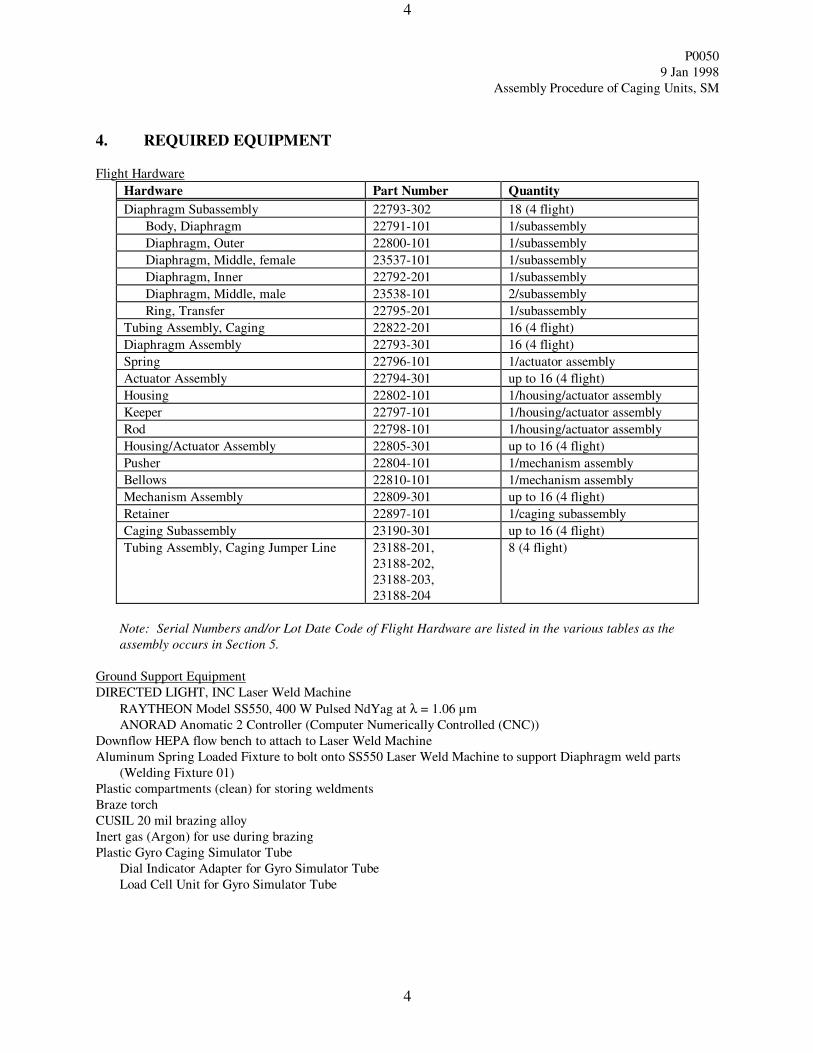
4. REQUIRED EQUIPMENT
Flight Hardware
Hardware Part Number Quantity
Diaphragm Subassembly 22793-302 18 (4 flight)
Body, Diaphragm 22791-101 1/subassembly
Diaphragm, Outer 22800-101 1/subassembly
Diaphragm, Middle, female 23537-101 1/subassembly
Diaphragm, Inner 22792-201 1/subassembly
Diaphragm, Middle, male 23538-101 2/subassembly
Ring, Transfer 22795-201 1/subassembly
Tubing Assembly, Caging 22822-201 16 (4 flight)
Diaphragm Assembly 22793-301 16 (4 flight)
Spring 22796-101 1/actuator assembly
Actuator Assembly 22794-301 up to 16 (4 flight)
Housing 22802-101 1/housing/actuator assembly
Keeper 22797-101 1/housing/actuator assembly
Rod 22798-101 1/housing/actuator assembly
Housing/Actuator Assembly 22805-301 up to 16 (4 flight)
Pusher 22804-101 1/mechanism assembly
Bellows 22810-101 1/mechanism assembly
Mechanism Assembly 22809-301 up to 16 (4 flight)
Retainer 22897-101 1/caging subassembly
Caging Subassembly 23190-301 up to 16 (4 flight)
Tubing Assembly, Caging Jumper Line 23188-201,
23188-202,
23188-203,
23188-204
8 (4 flight)
Note: Serial Numbers and/or Lot Date Code of Flight Hardware are listed in the various tables as the
assembly occurs in Section 5.
Ground Support Equipment
DIRECTED LIGHT, INC Laser Weld Machine
RAYTHEON Model SS550, 400 W Pulsed NdYag at λ = 1.06 µm
ANORAD Anomatic 2 Controller (Computer Numerically Controlled (CNC))
Downflow HEPA flow bench to attach to Laser Weld Machine
Aluminum Spring Loaded Fixture to bolt onto SS550 Laser Weld Machine to support Diaphragm weld parts
(Welding Fixture 01)
Plastic compartments (clean) for storing weldments
Braze torch
CUSIL 20 mil brazing alloy
Inert gas (Argon) for use during brazing
Plastic Gyro Caging Simulator Tube
Dial Indicator Adapter for Gyro Simulator Tube
Load Cell Unit for Gyro Simulator Tube
P0050
9 Jan 1998
Assembly Procedure of Caging Units, SM
5
5
GSE for Diaphragm Assembly Travel Test
Housing (modified P/N 22802-101)
Keeper (modified P/N 22797-101)
Rod (modified P/N 22798-101)
Pusher (modified P/N 22804-101)
Bellows (modified P/N 22810-101)
Caging Retainer (modified P/N 22897-101)
Capillary tube adapter
one-inch Hex nuts for retainer bolts (3)
1/8 inch stainless steel tube with female VCR fittings on both end - approx 6’ long
1/4 inch flexible vacuum hose with female VCR fittings on both ends - approx 6’ long
POPE Scientific, Inc 1 liter vacuum flask
Fixture for holding Actuator Assembly for measurements
Mitutoyo 70040 Stand
Aluminum Cylinder for holding Actuator Assembly on Mitutoyo 70040 Stand
Caging Control Unit (CCU), and associated plumbing
Caging Line Adapter for connecting Caging tube to CCU
Plunger type dial indicator
V-block
Measurment GSE
Item Model Number Serial Number Calibration Date
Mitutoyo Dial Indicator IDC-112E 300650 4/29/97
Starrett Dial Indicator 25-231
CCU Pressure Transducer
Load Cell Force Meter Omega DP41-V
Varian Leak Detector Turbo Auto-test 960
Tools and Miscellaneous
Tetrafluorethane (TF) Solvent - .05 µm filtered Freon
Chemtronics Freez-It 2000 can of Tetrafluorethane 1,1,1,2 (-51 °C)
Chemtronics Ultra-jet Duster can of Tetrafluorethane 1,1,1,2 (-51 °C)
Bottle of Ethyl alcohol
Monofilament nylon line
P0050
9 Jan 1998
Assembly Procedure of Caging Units, SM
6
6
5. ASSEMBLY, WELD, AND TEST OF THE DIAPHRAGM SUBASSEMBLY, P/N
22793-302
5.1 Assembly and Weld of Diaphragm Subassembly (Weldments 1 - 5)
This task module takes place at Directed Light, Inc in San Jose. It assumes (1) the diaphragm
subassembly parts have been cleaned, magnetically screened, and released.
(2) the weld parameters for the SS550 Laser Welder have been determined and set;
(3) the laminar flow bench for assembly and the downflow bench for welding are in place and ready for
use; (4) the Turbo Leak Detector (LD) is at the vendor and has been prepped (rough pumped and
calibrated).
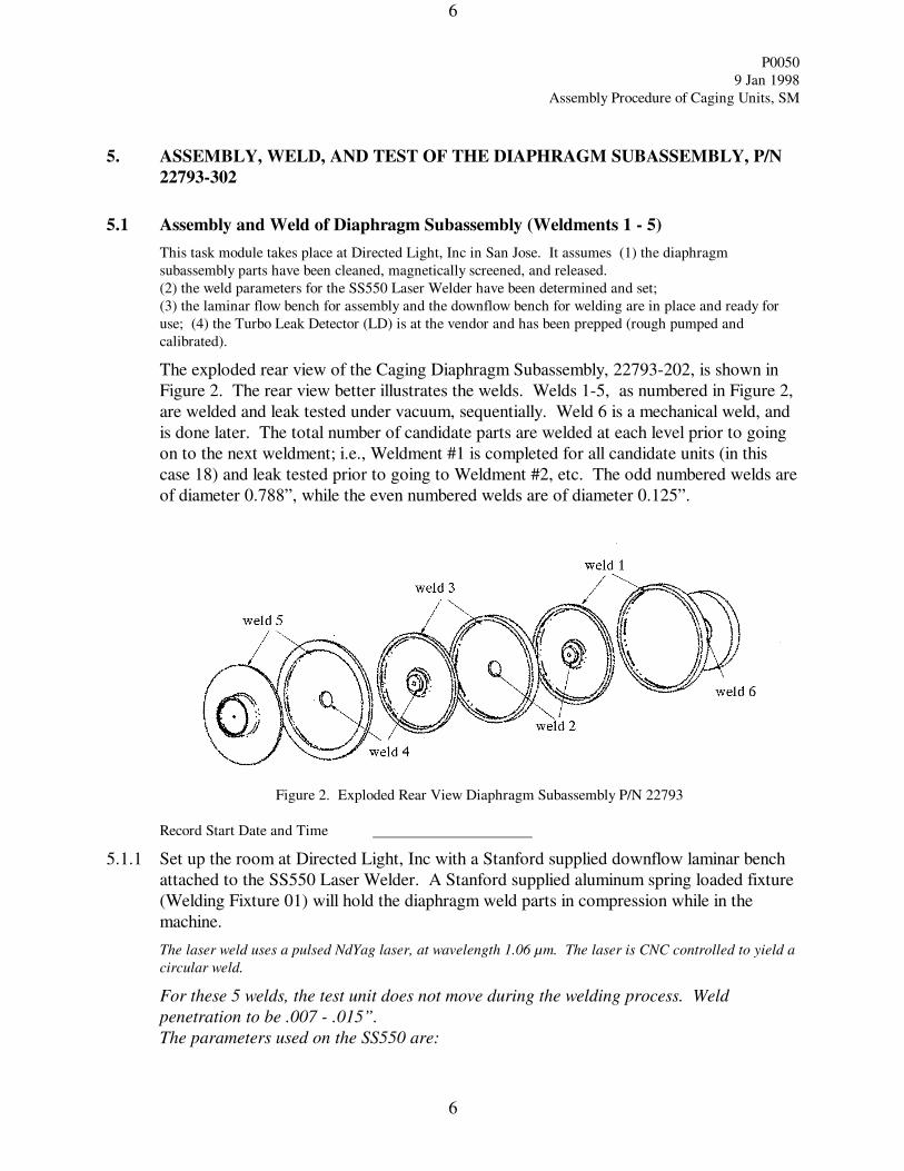
The exploded rear view of the Caging Diaphragm Subassembly, 22793-202, is shown in
Figure 2. The rear view better illustrates the welds. Welds 1-5, as numbered in Figure 2,
are welded and leak tested under vacuum, sequentially. Weld 6 is a mechanical weld, and
is done later. The total number of candidate parts are welded at each level prior to going
on to the next weldment; i.e., Weldment #1 is completed for all candidate units (in this
case 18) and leak tested prior to going to Weldment #2, etc. The odd numbered welds are
of diameter 0.788”, while the even numbered welds are of diameter 0.125”.
Figure 2. Exploded Rear View Diaphragm Subassembly P/N 22793
Record Start Date and Time
5.1.1 Set up the room at Directed Light, Inc with a Stanford supplied downflow laminar bench
attached to the SS550 Laser Welder. A Stanford supplied aluminum spring loaded fixture
(Welding Fixture 01) will hold the diaphragm weld parts in compression while in the
machine.
The laser weld uses a pulsed NdYag laser, at wavelength 1.06 µm. The laser is CNC controlled to yield a
circular weld.
For these 5 welds, the test unit does not move during the welding process. Weld
penetration to be .007 - .015”.
The parameters used on the SS550 are:
P0050
9 Jan 1998
Assembly Procedure of Caging Units, SM
7
7
pulse width : 3.1 ms
pulse frequency: 20 pulses/sec
average power: 288 W
input power: 10.8 kW
focus: sharp focus, focal length 6 inches
nozzle size 0.25”
assist gas: Argon
assist gas pressure: 40 scfh (standard cubic feet per hour)
feed rate, using X-Y interpolator (determines run time) :
F30, Large weldments (odd numbers)
F20, Small weldments (even numbers)
5.1.2 Weldment #1 : Weld P/N 22792-201 to P/N 23538-101
5.1.2.1 On the clean room bench, clean P/N 23538-101 and P/N 22792-201 by thoroughly
spraying with Freon spray. Shrink-fit P/N 23538-101 inside the P/N 22792-201 outer
flange by cooling to a minimum temperature differential of 30 °C by spraying with
tetrafluorethane spray. Fit surfaces of mating welded parts to be flush.
5.1.2.2 Weld this mating diameter (Weldment#1) per vendor weld procedure, using above
parameters.
5.1.2.3 Put the weldment on the adapter unit of the Leak Detector. Leak test this part per
Procedure P0054. Document leak rate in Table 1 below. If leak rate is = 10-8
sccs
He, accept this part; if leak rate is > 10-8
sccs He, repeat 5.1.2.2. If leak rate is > 10-8
sccs He, after second weld, remove this unit from flight inventory. Store accepted
weldments in clean, plastic, numbered compartments.
5.1.2.4 Using next P/N 23538-101 and P/N 22792-201, repeat steps 5.1.2.1 through 5.1.2.3
until all candidate units completed. Record leak rates in Table 1.
5.1.3 Weldment #2 : Weld completed Weldment #1 to P/N 23537-101
5.1.3.1 Take the completed Weldment #1, and a P/N 23537-101 on the clean room bench,
clean parts to be welded by thoroughly spraying with TF spray. Insert the inner flange
of Weldment #1 into the inner hole of P/N 23537-101. Shrink-fit not required. Fit
surfaces of mating welded parts to be flush.
5.1.3.2 Weld this mating diameter (Weldment#2) per vendor weld procedure, using above
parameters.
5.1.3.3 Put the weldment on the adapter unit of the Leak Detector. Leak test this part per
Procedure P0054. Document leak rate in Table 1 below. If leak rate is = 10-8
sccs
He, accept this part; if leak rate is > 10-8
sccs He, repeat 5.1.3.2. If leak rate is > 10-8
sccs He, after second weld, remove this unit from flight inventory. Store accepted
weldments in clean, plastic, numbered compartments.
5.1.3.4 Using next Weldment #2 and P/N 23537-101, repeat steps 5.1.3.1 through 5.1.3.3
until all candidate units completed. Record leak rates in Table 1.
5.1.4 Weldment #3 : Weld completed Weldment #2 part to new P/N 23538-101
P0050
9 Jan 1998
Assembly Procedure of Caging Units, SM
8
8
5.1.4.1 Take the completed Weldment #2, and a new P/N 23538-101 on the clean room
bench, clean parts to be welded by thoroughly spraying with TF spray. Shrink-fit P/N
23538-101 inside the weldment P/N 23537-101 outer flange by cooling to a minimum
temperature differential of 30 °C by spraying with tetrafluorethane spray. Fit surfaces
of mating welded parts to be flush.
5.1.4.2 Weld this mating diameter (Weldment#3) per vendor weld procedure, using above
parameters.
5.1.4.3 Put the weldment on the adapter unit of the Leak Detector. Leak test this part per
Procedure P0054. Document leak rate in Table 1 below. If leak rate is = 10-8
sccs
He, accept this part; if leak rate is > 10-8
sccs He, repeat 5.1.4.2. If leak rate is > 10-8
sccs He, after second weld, remove this unit from flight inventory. Store accepted
weldments in clean, plastic, numbered compartments.
5.1.4.4 Using next Weldment #3 and P/N 23538-101, repeat steps 5.1.4.1 through 5.1.4.3
until all candidate units completed. Record leak rates in Table 1.
5.1.5 Weldment #4 : Weld completed Weldment #3 part to new P/N 22800-101
5.1.5.1 Take the completed Weldment #3, and a P/N 22800-101 on the clean room bench,
clean parts to be welded by thoroughly spraying with TF spray. Insert the inner flange
of Weldment #3 into the inner hole of P/N 22800-101. Shrink-fit not required. Fit
surfaces of mating welded parts to be flush.
5.1.5.2 Weld this mating diameter (Weldment#4) per vendor weld procedure, using above
parameters.
5.1.5.3 Put the weldment on the adapter unit of the Leak Detector. Leak test this part per
Procedure P0054. Document leak rate in Table 1 below. If leak rate is = 10-8
sccs
He, accept this part; if leak rate is > 10-8
sccs He, repeat 5.1.5.2. If leak rate is > 10-8
sccs He, after second weld, remove this unit from flight inventory. Store accepted
weldments in clean, plastic, numbered compartments.
5.1.5.4 Using next Weldment #3 and P/N 22800-101, repeat steps 5.1.5.1 through 5.1.5.3
until all candidate units completed. Record leak rates in Table 1.
5.1.6 Weldment #5 : Weld completed Weldment #4 part to new P/N 22791-101
5.1.6.1 Take the completed Weldment #4, and a new P/N 22791-101 on the clean room
bench, clean parts to be welded by thoroughly spraying with TF spray. Shrink-fit P/N
22791-101 inside the weldment P/N 22800-101 outer flange by cooling to a minimum
temperature differential of 30 °C by spraying with tetrafluorethane spray. Fit surfaces
of mating welded parts to be flush.
5.1.6.2 Weld this mating diameter (Weldment#5) per vendor weld procedure, using above
parameters.
P0050
9 Jan 1998
Assembly Procedure of Caging Units, SM
9
9
5.1.6.3 Put the weldment on the adapter unit of the Leak Detector. Leak test this part per
Procedure P0054. Document leak rate in Table 1 below. If leak rate is = 10-8
sccs
He, accept this part; if leak rate is > 10-8
sccs He, repeat 5.1.6.2. If leak rate is > 10-8
sccs He, after second weld, remove this unit from flight inventory. Store accepted
weldments in clean, plastic, numbered compartments.
5.1.6.4 Using next Weldment #4 and P/N 22791-101, repeat steps 5.1.6.1 through 5.1.6.3
until all candidate units completed. Record leak rates in Table 1.
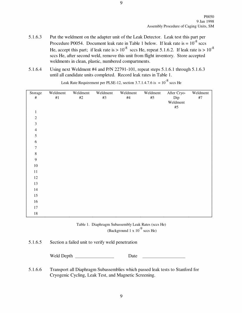
Table 1. Diaphragm Subassembly Leak Rates (sccs He)
(Background 1 x 10⁻⁹
sccs He)
5.1.6.5 Section a failed unit to verify weld penetration
Weld Depth Date
5.1.6.6 Transport all Diaphragm Subassemblies which passed leak tests to Stanford for
Cryogenic Cycling, Leak Test, and Magnetic Screening.
Leak Rate Requirement per PLSE-12, section 3.7.1.4.7.6 is = 10-8
sccs He
Storage
#
Weldment
#1
Weldment
#2
Weldment
#3
Weldment
#4
Weldment
#5
After Cryo-
Dip
Weldment
#5
Weldment
#7
1
2
3
4
5
6
7
8
9
10
11
12
13
14
15
16
17
18
P0050
9 Jan 1998
Assembly Procedure of Caging Units, SM
10
10
Completed: ___________________________________ date: _ _
Responsible Engineer
Discrepancies if any:
P0050
9 Jan 1998
Assembly Procedure of Caging Units, SM
11
11
5.2 LN2 Dip, Leak Test and Mag Test of Diaphragm Subassembly
The LN2 dip procedure takes place at Stanford HEPL, Room 22. The Leak Test will be done in the Class 1000
Clean Room, and the Magnetic Test will be done in the HEPL Magnetics Lab.
Record Start Date and Time
5.2.1 Prepare a standard 15” LN2 dewar flask and fill to a depth of approximately 6 inches with
Liquid Nitrogen.
5.2.2 Prepare a monofilament nylon tie line to support the Diaphragm Subassembly such that
there are markers which indicate the subassembly is (a) in the liquid, (b) in the cold vapor,
or (c) in the warm vapor.
5.2.3 Thermal cycle the unit according to Cryo Dip Procedure P0063.
5.2.4 After thermal cycling, store in clean numbered storage compartments. Repeat cryo-dip
procedure for all candidate units, and store in numbered compartments.
5.2.5 After thermal cycling all candidate units, carry the units to the Class 1000 Clean room
where the Leak Detector is set up. Perform vacuum leak test of each unit according to
P0054. Record leak rate in Table 1.
5.2.6 After leak test, clean subassembly with TF spray according to P0059, bag, and store in
numbered compartment.
5.2.7 Send to Stanford Magnetics Lab for magnetic testing, according to P0057A.
Completed: ___________________________________ date:
Responsible Engineer
Discrepancies if any:
P0050
9 Jan 1998
Assembly Procedure of Caging Units, SM
12
12
6. ASSEMBLY, BRAZE, AND TEST OF TUBING ASSEMBLY, CAGING, P/N
22822-201
6.1 Assembly and Braze of Tubing Assembly, Caging
This task module takes place in Stanford’s HEPL building Tube Shop, Rm 141. It assumes the Tubing
Assembly parts have been cleaned, magnetically screened, and released.
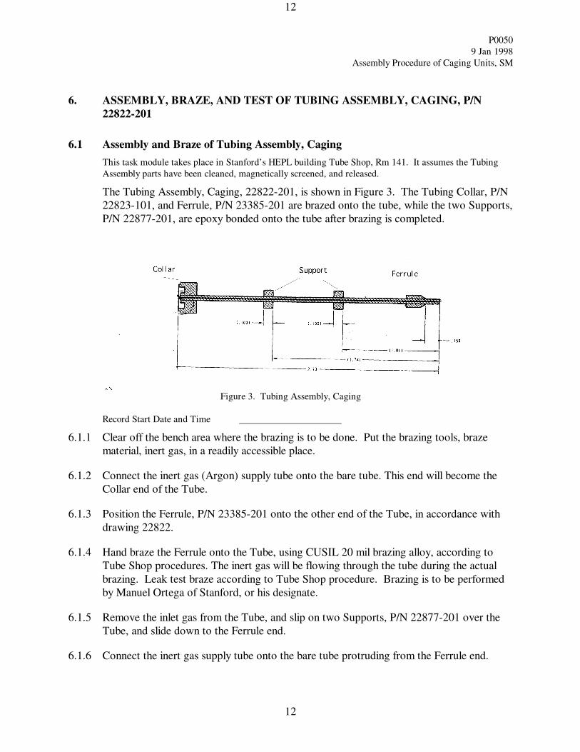
The Tubing Assembly, Caging, 22822-201, is shown in Figure 3. The Tubing Collar, P/N
22823-101, and Ferrule, P/N 23385-201 are brazed onto the tube, while the two Supports,
P/N 22877-201, are epoxy bonded onto the tube after brazing is completed.
Figure 3. Tubing Assembly, Caging
Record Start Date and Time
6.1.1 Clear off the bench area where the brazing is to be done. Put the brazing tools, braze
material, inert gas, in a readily accessible place.
6.1.2 Connect the inert gas (Argon) supply tube onto the bare tube. This end will become the
Collar end of the Tube.
6.1.3 Position the Ferrule, P/N 23385-201 onto the other end of the Tube, in accordance with
drawing 22822.
6.1.4 Hand braze the Ferrule onto the Tube, using CUSIL 20 mil brazing alloy, according to
Tube Shop procedures. The inert gas will be flowing through the tube during the actual
brazing. Leak test braze according to Tube Shop procedure. Brazing is to be performed
by Manuel Ortega of Stanford, or his designate.
6.1.5 Remove the inlet gas from the Tube, and slip on two Supports, P/N 22877-201 over the
Tube, and slide down to the Ferrule end.
6.1.6 Connect the inert gas supply tube onto the bare tube protruding from the Ferrule end.
P0050
9 Jan 1998
Assembly Procedure of Caging Units, SM
13
13
6.1.7 Position the Collar, P/N 22823-101 on the other end of the Tube, in accordance with
drawing 22822.
6.1.8 Hand braze the Collar onto the Tube, using CUSIL 20 mil brazing alloy, according to
Tube Shop procedures. The inert gas will be flowing through the tube during the actual
brazing. Leak test braze according to Tube Shop procedure. Brazing is to be performed
by Manuel Ortega of Stanford, or his designate.
6.1.9 After leak test, clean subassembly with TF spray according to procedure P0059, bag, and
store in numbered compartment.
6.1.10 With new parts, repeat 6.1.1 through 6.1.9 until 16 assemblies are completed.
6.2 LN2 Dip, Leak Test, Epoxy Bond, and Mag Test of Tubing Assembly
The LN2 dip procedure takes place at Stanford HEPL, Class 1000 Clean Room bench. The Leak Test will
be done in the Class 1000 Clean Room.
Record Start Date and Time
6.2.1 Prepare a LN2 dewar flask of height sufficient to hold the entire assembly in the liquid,
cold vapor, and warm vapor, and fill to a depth of approximately 6 inches with Liquid
Nitrogen.
6.2.2 Prepare a pulley arrangement above the bench, such that a line can be plumbed into the
dewar flask.
6.2.3 Prepare a monofilament nylon tie line to support the Tubing Assembly such that there are
markers visible above the flask, which indicate the assembly is (a) in the liquid, (b) in the
cold vapor, or (c) in the warm vapor.
6.2.4 Thermal cycle the unit according to Cryo Dip Procedure P0063.
6.2.5 After thermal cycling, store in clean numbered storage compartments. Repeat cryo-dip
procedure for all candidate units, and store in numbered compartments.
6.2.6 After thermal cycling all candidate units, perform vacuum leak test of each unit according
to P0054. Record leak rate in Table 2.
6.2.7 After leak test, epoxy bond the two Supports per tube according to Bonding Procedure
P0355.
6.2.8 Clean subassembly with TF spray according to P0059, bag, and store in numbered
compartment.
6.2.9 Send to Stanford Magnetics Lab for magnetic testing, according to P0057A.
P0050
9 Jan 1998
Assembly Procedure of Caging Units, SM
14
14
Tubing Assembly
Unit Number
Leak Rate (sccs He)
Reqmt: 1 x 10⁻⁸ sccs He
Accepted
(Y or N)
Collar Ferrule
Table 2. Leak Rate of Tubing Assembly After Braze
Completed: ___________________________________ date:
Responsible Engineer
Discrepancies if any:
P0050
9 Jan 1998
Assembly Procedure of Caging Units, SM
15
15
7. ASSEMBLY, WELD, AND TEST OF DIAPHRAGM ASSEMBLY, P/N 22793-301
7.1 Assembly and Weld of Diaphragm Assembly (Weldments 6 & 7)
This task module takes place at Directed Light, Inc in San Jose, CA. It assumes (1) the diaphragm subassembly
weldments 1-5 have been completed, thermal cycled, leak tested, cleaned, magnetically screened, and released. (2)
the tubing assemblies, P/N 22822-201, have been assembled, cleaned, magnetically screened, and released. (3) the
weld parameters for the SS550 Laser Welder have been determined and set.
Record Start Date and Time
7.1.1 Set up the room at Directed Light, Inc with a Stanford supplied downflow laminar bench
attached to the SS550 Laser Welder. A Stanford supplied aluminum spring loaded fixture
will hold the diaphragm weld parts in compression while in the machine.
For Weldment #6, the test unit does not move during the welding process. For Weldment #7, the test unit
rotates, while the laser is held in place. Weld penetration to be .007 - .015”.
Weldment #6 of the Caging Diaphragm Subassembly, 22793-302, is shown in Figure 2.
This weld is mechanical only, and not leak tested under vacuum. Weldment #7 is shown in
Figure 4 below.
The parameters used on the SS550 are:
pulse width : 3.1 ms
pulse frequency: 20 pulses/sec
average power: 288 W
input power: 10.8 kW
focus: sharp focus, focal length 6 inches
nozzle size 0.25”
assist gas: Argon
assist gas pressure: 40 scfh (standard cubic feet per hour)
feed rate, using X-Y interpolator (determines run time) :
F20, Small weldments (even numbers)
7.1.2 Weldment #6 : Weld completed Weldment #5 part to new P/N 22795-201
7.1.2.1 Take the completed Weldment #5, and a P/N 22795-201 on the clean room bench,
clean parts to be welded by thoroughly spraying with TF spray. Insert the inner flange
of Weldment #5 into the inner hole of P/N 22800-101. Shrink-fit not required. Fit
surfaces of mating welded parts to be flush.
7.1.2.2 Weld this mating diameter (Weldment#6) per vendor weld procedure, using Stanford
approved parameters.
7.1.2.3 Using new Weldment #5 and P/N 22795-201, repeat steps 7.1.2.1 through 7.1.2.2
until all candidate units completed.
P0050
9 Jan 1998
Assembly Procedure of Caging Units, SM
16
16
Figure 4. Weldment #7 of Diaphragm Assembly
7.1.3 Weldment #7 : Weld completed Weldment #6 part to new P/N 22822-201
Weldment #7 of the Caging Diaphragm Assembly, P/N 22793-301, is shown in Figure 4.
This weld is of the Tubing Assembly, P/N 22822-201, to the Diaphragm Subassembly P/N
22793-302 (Weldment #6).
For Weldment #7, the test unit is placed in a Rotator fixture so that the unit rotates
during the welding process. Weld penetration to be .007 - .015”.
The parameters used on the SS550 are:
pulse width : 1.9 ms
pulse frequency: 20 pulses/sec
(average power: 150.8 W)
focus: sharp
feed rate: F100 (determines run time)
7.1.3.1 Take the completed Weldment #6, and a Tubing Assembly, P/N 22822-201, on the
clean room bench, clean parts to be welded by thoroughly spraying with Freon. To
verify flow through the Tubing Assembly, insert the end of the Tubing Assembly tube
to the plastic tube which attaches to the can of prefiltered Freon. The Tubing
Assembly tube will just fit into the Freon tube. Spray the Freon and visually check that
flow is coming through the Tubing Assembly tube.
7.1.3.2 Insert P/N 22822-201 into the inner flange of P/N 22791-101 of Weldment #6.
Shrink-fit not required. Fit surfaces of mating welded parts to be flush.
7.1.3.3 Weld this mating diameter (Weldment#7) per vendor weld procedure, using Stanford
approved parameters.
P0050
9 Jan 1998
Assembly Procedure of Caging Units, SM
17
17
7.1.3.4 Using next Weldment #6 and P/N 22822-201, repeat steps 7.1.3.1 through 7.1.3.3
until all candidate units completed.
7.1.3.5 Put the Weldment #7 on the adapter unit of the Leak Detector. Leak test this part per
Procedure P0054. Enter leak rate in Table 1. If leak rate is < 10-8
sccs He, accept this
part; if leak rate is > 10-8
sccs He, repeat 7.1.3.3. If leak rate is > 10-8
sccs He, after
second weld, remove this unit from flight inventory.
7.1.3.6 Upon completion of leak test of all Weldment #7s, return to Stanford.
7.2 Pressure Test of Diaphragm Assembly
The candidate Weldment #7s, the Caging Diaphragm Assembly, P/N 22793-301, which passed leak test in
the previous step, are brought back to Stanford HEPL to test for free movement of the diaphragm. The
test is done in the Class 1000 MGP Clean Room. Hereafter, buildup of the Caging Subassembly will not
leave the Class 1000 Room, prior to completion.
The plastic Gyro Caging Simulator Tube depicts the gyro cavity and housing for the purpose of testing the
caging unit.
7.2.1 Place the completed Weldment #7 into the GSE Housing (modified P/N 22802-101). The
housing will prevent over-travel during pressurization, and will be removed after test.
Screw the GSE Keeper (modified P/N 22797-101) into the Housing. Holding the Housing
Unit vertical, place the GSE Pusher (modified P/N 22804-101) / Bellows (modified P/N
22810-101) / Rod (modified P/N 22798-101) assembly on the keeper, held in place by
gravity.
7.2.2 Place the GSE Caging Retainer (modified P/N 22897-101), and capillary tubing adapter on
the assembly.
7.2.3 Place the unit into the bore of the plastic Gyro Caging Simulator Tube, Fixture #10, such
that the 3 holes in the Retainer go over the bolts of the Simulator Tube. Hand tighten the 3
one-inch Hex nuts onto the bolts.
Retainer
Pusher
Bellows
HousingKeeper (inside housing)
Rod
bore for dial indicator
bore for dial indicator screw
Retainer hex bolts (3)
Model of Gyro Housing upper halfGyro Caging
Simulator Tube
P0050
9 Jan 1998
Assembly Procedure of Caging Units, SM
18
18
NOTE: Everything GSE except Diaphragm Assembly. Drawing not to scale
Figure 5. Caging Assembly in Gyro Caging Simulator Tube
7.2.4 Install the Mitutoyo Model IDC-112E Dial Indicator in the Simulator Tube. Place the
Simulator on a V-block, with the Dial Indicator in place.
7.2.5 Connect the tubing assembly ferrule to the compression fitting adapter which adapts to the
VCR fitting. Connect to the VCR fitting on the 1/8 inch stainless steel tube. Connect the
VCR on the other end of the tube to the CCU as shown in Figure 6 below.
Regulator
Metering Valve
Vent Valve
GHe Supply Bottle
Input Pressure Meter
Regulated Pressure Meter
Output Pressure Transducer
Caging Control Unit
V1
V2
V3
V4
0.5µ filter
300 cc ballast
Support on V-block
Manual Valve
Filter
Vacuum Compression Ring (VCR) Connector
1/8" ss tube with VCR fittings on each end
compression fitting adapter to VCR
Not to scale
Figure 6. Set-up of Pressure Test of Diaphragm Subassembly (not to scale)
7.2.6 Configure the manual valves to their nominal conditions as follows:
V1 open, V2 open, V3 open, V4 closed, Metering Valve closed. The metering valve
shall be used to control the rate of rise.
7.2.7 Slowly build up pressure at a rate of approximately 1 psid per second, using the metering
valve. Note the pressure at which travel is detected, and record in Table 2. If no travel is
detected by 65 psid, relax the pressure, and bring it up again.
7.2.8 Continue building pressure at a rate of approximately 1 psid per second, not to exceed 160
psid. Record travel vs pressure at 10 psid increments in Table 3. Approximately 28 mils
of travel at 160 psid, with near linear travel is desired. Limit travel to 32 mils.
NOTE: Verify that at 20 psid, travel is = .008 inch. This verifies Requirement #
3.7.1.4.7.8 of the Payload Spec, F277277.
7.2.9 After completing pressure test of unit, close off pressure at V2 and open V4 to vent to one
atmosphere.
7.2.10 Disconnect the 1/8 inch ss tube from the caging unit at the adapter end of the tube.
P0050
9 Jan 1998
Assembly Procedure of Caging Units, SM
19
19
7.2.11 Unscrew the 3 Hex nuts holding the Caging Retainer onto the Simulator. Remove the
Caging Unit out of the Simulator.
7.2.12 Remove the Diaphragm Assembly out of the Housing Unit, by reversing the order of
assembly in 7.2.1.
7.2.13 Assign serial number to this assembly if the unit is accepted at this stage, and record in
Table 3. Diamond scribe the serial number into the back outer surface (tube side) of the
Diaphragm Assembly. Place the Diaphragm Assembly into a clean marked container.
7.2.14 Repeat steps 7.2.1 through 7.2.13 until all Diaphragm Assemblies are tested.
P0050
9 Jan 1998
Assembly Procedure of Caging Units, SM
20
20
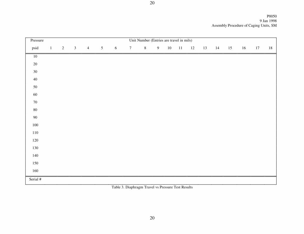
Pressure Unit Number (Entries are travel in mils)
psid 1 2 3 4 5 6 7 8 9 10 11 12 13 14 15 16 17 18
10
20
30
40
50
60
70
80
90
100
110
120
130
140
150
160
Serial #
Table 3. Diaphragm Travel vs Pressure Test Results
P0050
9 Jan 1998
Assembly Procedure of Caging Units, SM
21
21
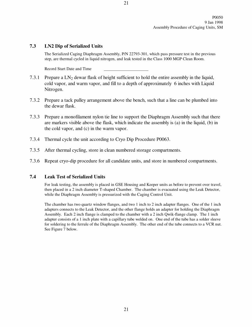
7.3 LN2 Dip of Serialized Units
The Serialized Caging Diaphragm Assembly, P/N 22793-301, which pass pressure test in the previous
step, are thermal cycled in liquid nitrogen, and leak tested in the Class 1000 MGP Clean Room.
Record Start Date and Time
7.3.1 Prepare a LN2 dewar flask of height sufficient to hold the entire assembly in the liquid,
cold vapor, and warm vapor, and fill to a depth of approximately 6 inches with Liquid
Nitrogen.
7.3.2 Prepare a tack pulley arrangement above the bench, such that a line can be plumbed into
the dewar flask.
7.3.3 Prepare a monofilament nylon tie line to support the Diaphragm Assembly such that there
are markers visible above the flask, which indicate the assembly is (a) in the liquid, (b) in
the cold vapor, and (c) in the warm vapor.
7.3.4 Thermal cycle the unit according to Cryo Dip Procedure P0063.
7.3.5 After thermal cycling, store in clean numbered storage compartments.
7.3.6 Repeat cryo-dip procedure for all candidate units, and store in numbered compartments.
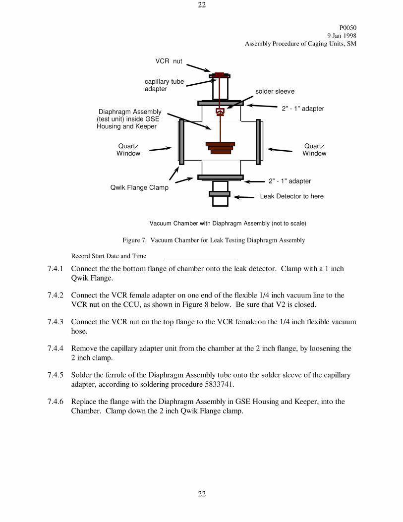
7.4 Leak Test of Serialized Units
For leak testing, the assembly is placed in GSE Housing and Keeper units as before to prevent over travel,
then placed in a 2 inch diameter T-shaped Chamber. The chamber is evacuated using the Leak Detector,
while the Diaphragm Assembly is pressurized with the Caging Control Unit.
The chamber has two quartz window flanges, and two 1 inch to 2 inch adapter flanges. One of the 1 inch
adapters connects to the Leak Detector, and the other flange holds an adapter for holding the Diaphragm
Assembly. Each 2 inch flange is clamped to the chamber with a 2 inch Qwik-flange clamp. The 1 inch
adapter consists of a 1 inch plate with a capillary tube welded on. One end of the tube has a solder sleeve
for soldering to the ferrule of the Diaphragm Assembly. The other end of the tube connects to a VCR nut.
See Figure 7 below.
P0050
9 Jan 1998
Assembly Procedure of Caging Units, SM
22
22
2" - 1" adapter Qwik Flange Clamp
Quartz Window
VCR nut
2" - 1" adapter
Leak Detector to here
Quartz Window
capillary tube adapter solder sleeve
Diaphragm Assembly (test unit) inside GSE Housing and Keeper
Vacuum Chamber with Diaphragm Assembly (not to scale)
Figure 7. Vacuum Chamber for Leak Testing Diaphragm Assembly
Record Start Date and Time
7.4.1 Connect the the bottom flange of chamber onto the leak detector. Clamp with a 1 inch
Qwik Flange.
7.4.2 Connect the VCR female adapter on one end of the flexible 1/4 inch vacuum line to the
VCR nut on the CCU, as shown in Figure 8 below. Be sure that V2 is closed.
7.4.3 Connect the VCR nut on the top flange to the VCR female on the 1/4 inch flexible vacuum
hose.
7.4.4 Remove the capillary adapter unit from the chamber at the 2 inch flange, by loosening the
2 inch clamp.
7.4.5 Solder the ferrule of the Diaphragm Assembly tube onto the solder sleeve of the capillary
adapter, according to soldering procedure 5833741.
7.4.6 Replace the flange with the Diaphragm Assembly in GSE Housing and Keeper, into the
Chamber. Clamp down the 2 inch Qwik Flange clamp.
P0050
9 Jan 1998
Assembly Procedure of Caging Units, SM
23
23
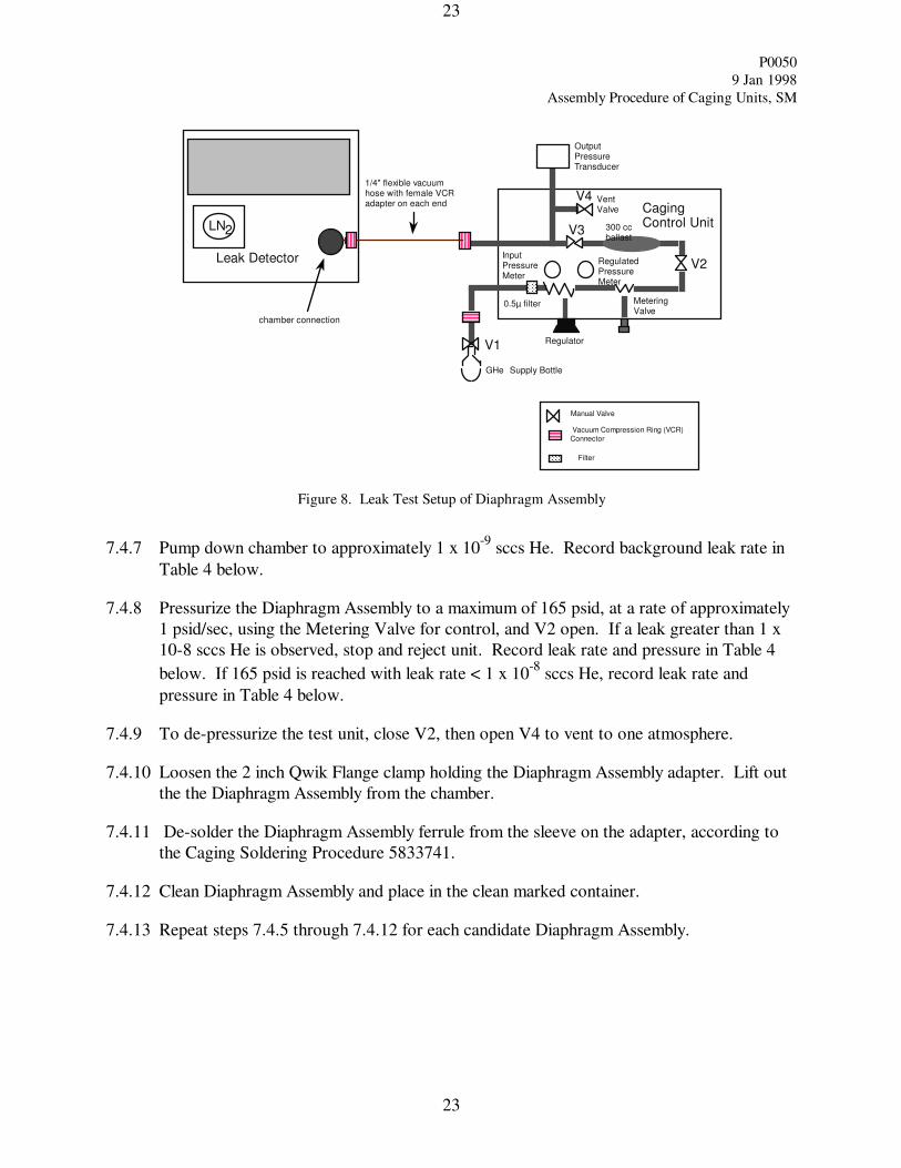
Manual Valve
Filter
Vacuum Compression Ring (VCR) Connector
Regulator
Metering Valve
Vent Valve
GHe Supply Bottle
Input Pressure Meter
Regulated Pressure Meter
Output Pressure Transducer
LN2
Leak Detector
Caging Control Unit
V1
V2
V3
V4
0.5µ filter
300 cc ballast
1/4" flexible vacuum hose with female VCR adapter on each end
chamber connection
Figure 8. Leak Test Setup of Diaphragm Assembly
7.4.7 Pump down chamber to approximately 1 x 10⁻⁹
sccs He. Record background leak rate in
Table 4 below.
7.4.8 Pressurize the Diaphragm Assembly to a maximum of 165 psid, at a rate of approximately
1 psid/sec, using the Metering Valve for control, and V2 open. If a leak greater than 1 x
10-8 sccs He is observed, stop and reject unit. Record leak rate and pressure in Table 4
below. If 165 psid is reached with leak rate < 1 x 10⁻⁸
sccs He, record leak rate and
pressure in Table 4 below.
7.4.9 To de-pressurize the test unit, close V2, then open V4 to vent to one atmosphere.
7.4.10 Loosen the 2 inch Qwik Flange clamp holding the Diaphragm Assembly adapter. Lift out
the the Diaphragm Assembly from the chamber.
7.4.11 De-solder the Diaphragm Assembly ferrule from the sleeve on the adapter, according to
the Caging Soldering Procedure 5833741.
7.4.12 Clean Diaphragm Assembly and place in the clean marked container.
7.4.13 Repeat steps 7.4.5 through 7.4.12 for each candidate Diaphragm Assembly.
P0050
9 Jan 1998
Assembly Procedure of Caging Units, SM
24
24
Leak Rate Requirement per PLSE-12, section 3.7.1.4.7.6 is = 10-8
sccs He
Serial Number Background (sccsHe) Leak Rate
(sccsHe)
Pressure for Leak
Rate (psid)
Accepted
(Y or N)
Table 4. Leak Test Results of Diaphragm Subassemblies
Completed: ___________________________________ date:
Responsible Engineer
Discrepancies if any:
P0050
9 Jan 1998
Assembly Procedure of Caging Units, SM
25
25
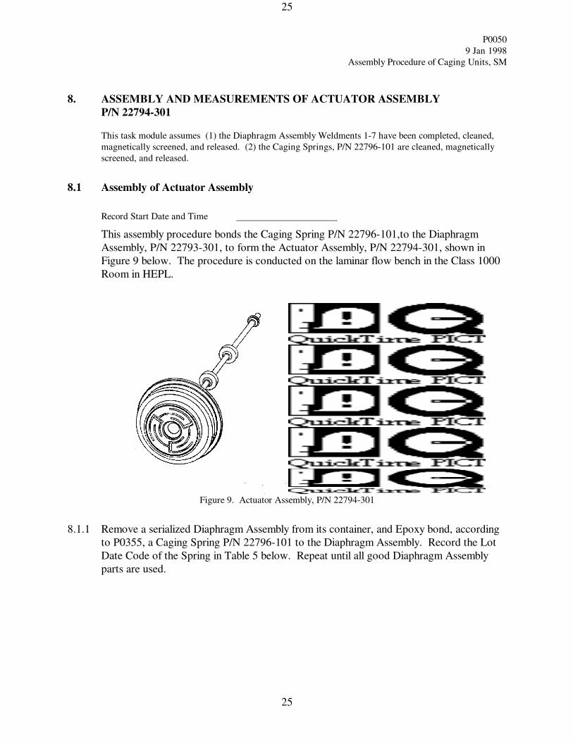
8. ASSEMBLY AND MEASUREMENTS OF ACTUATOR ASSEMBLY
P/N 22794-301
This task module assumes (1) the Diaphragm Assembly Weldments 1-7 have been completed, cleaned,
magnetically screened, and released. (2) the Caging Springs, P/N 22796-101 are cleaned, magnetically
screened, and released.
8.1 Assembly of Actuator Assembly
Record Start Date and Time
This assembly procedure bonds the Caging Spring P/N 22796-101,to the Diaphragm
Assembly, P/N 22793-301, to form the Actuator Assembly, P/N 22794-301, shown in
Figure 9 below. The procedure is conducted on the laminar flow bench in the Class 1000
Room in HEPL.
Figure 9. Actuator Assembly, P/N 22794-301
8.1.1 Remove a serialized Diaphragm Assembly from its container, and Epoxy bond, according
to P0355, a Caging Spring P/N 22796-101 to the Diaphragm Assembly. Record the Lot
Date Code of the Spring in Table 5 below. Repeat until all good Diaphragm Assembly
parts are used.
P0050
9 Jan 1998
Assembly Procedure of Caging Units, SM
26
26
Diaphragm Assembly
(P/N 22793-301)
Serial Number
Caging Spring
(P/N 22796-101)
Lot Date Code
Table 5. Serial Numbers of Diaphragm Assembly and Caging Spring
NOTE: The Actuator Assembly Serial Numbers are identical to the Diaphragm Assembly Serial
Numbers, after installation of the Caging Spring.
8.2 Dimensional Measurements of Actuator Assembly
Dimensional measurements are made of the Actuator Assembly, so that match ups can be made with the
Housing, P/N 22802-101, and Rod, P/N 22798-101. The housings and rods are matched up with the
Actuator Assembly, and sent back out for machining, as required.
Record Start Date and Time
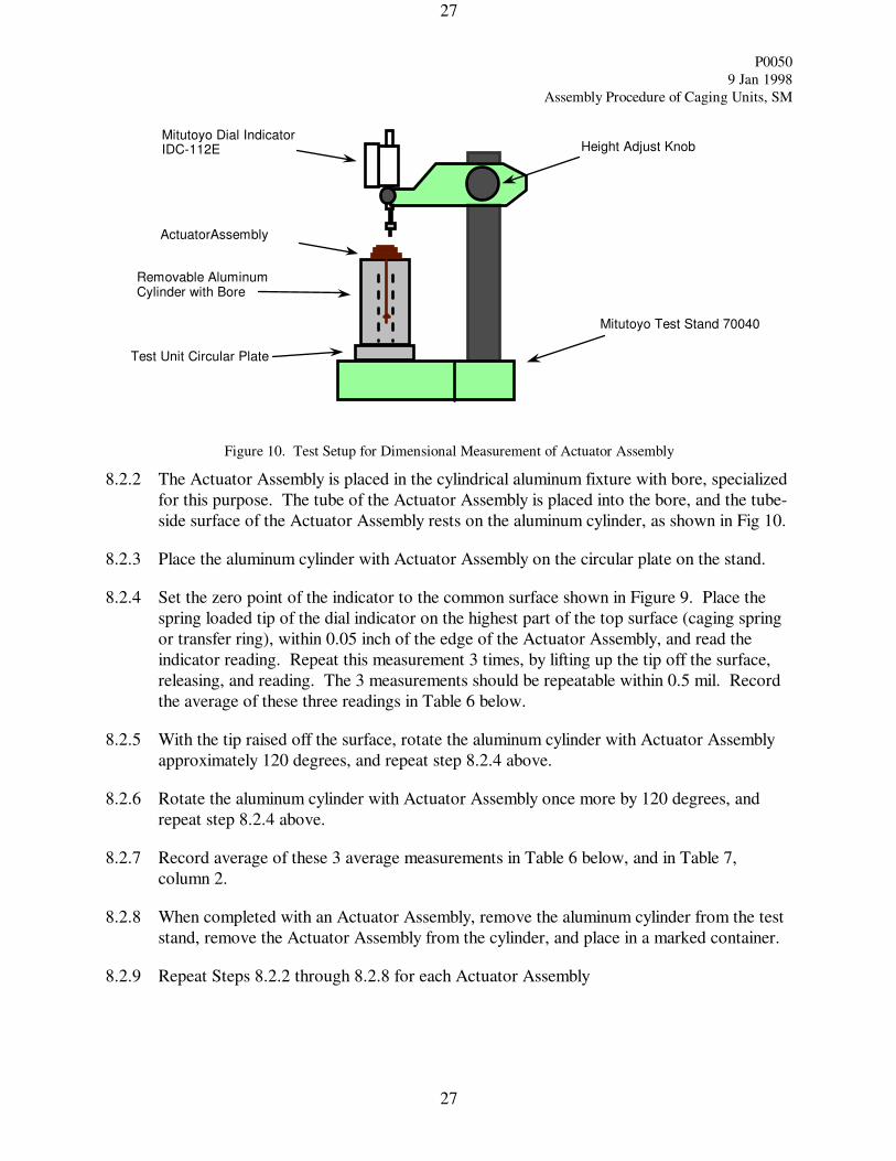
8.2.1 The Mitutoyo Model IDC-112E dial indicator, S/N 300650, with tip, is installed in the
Mitutoyo 70040 stand, as shown in Figure 10 below.
P0050
9 Jan 1998
Assembly Procedure of Caging Units, SM
27
27
Height Adjust Knob
Mitutoyo Test Stand 70040
Mitutoyo Dial Indicator IDC-112E
Test Unit Circular Plate
Removable Aluminum Cylinder with Bore
ActuatorAssembly
Figure 10. Test Setup for Dimensional Measurement of Actuator Assembly
8.2.2 The Actuator Assembly is placed in the cylindrical aluminum fixture with bore, specialized
for this purpose. The tube of the Actuator Assembly is placed into the bore, and the tube-
side surface of the Actuator Assembly rests on the aluminum cylinder, as shown in Fig 10.
8.2.3 Place the aluminum cylinder with Actuator Assembly on the circular plate on the stand.
8.2.4 Set the zero point of the indicator to the common surface shown in Figure 9. Place the
spring loaded tip of the dial indicator on the highest part of the top surface (caging spring
or transfer ring), within 0.05 inch of the edge of the Actuator Assembly, and read the
indicator reading. Repeat this measurement 3 times, by lifting up the tip off the surface,
releasing, and reading. The 3 measurements should be repeatable within 0.5 mil. Record
the average of these three readings in Table 6 below.
8.2.5 With the tip raised off the surface, rotate the aluminum cylinder with Actuator Assembly
approximately 120 degrees, and repeat step 8.2.4 above.
8.2.6 Rotate the aluminum cylinder with Actuator Assembly once more by 120 degrees, and
repeat step 8.2.4 above.
8.2.7 Record average of these 3 average measurements in Table 6 below, and in Table 7,
column 2.
8.2.8 When completed with an Actuator Assembly, remove the aluminum cylinder from the test
stand, remove the Actuator Assembly from the cylinder, and place in a marked container.
8.2.9 Repeat Steps 8.2.2 through 8.2.8 for each Actuator Assembly
P0050
9 Jan 1998
Assembly Procedure of Caging Units, SM
28
28
Actuator
Assembly
Serial
Number
Average of 3
measurements at
Location 1
(mils)
Average of 3
measurements at
Location 2
(mils)
Average of 3
measurements at
Location 3
(mils)
Average of 3
Averages
(mils)
Reqmt: 0.270
±.005 inch
Table 6. Actuator Assembly Dimensional Measurements
Completed: ___________________________________ date:
Responsible Engineer
Discrepancies if any:
P0050
9 Jan 1998
Assembly Procedure of Caging Units, SM
29
29
9. MATCH MACHINING THE HOUSING (P/N 22802-101) AND ROD (P/N 22798-
101) TO THE ACTUATOR ASSEMBLY
This task module assumes (1) the Actuator Assemblies, P/N 228794-301, have been completed, and dimensionally
tested; (2) the Housings, P/N 22802-101, have been machined to their reference measurements; (3) the Caging
Rod Blanks, P/N 22798-102, have been completed.
9.1 Match Machining Housing and Rod to Actuator Assembly
The desired travel of the diaphragm, .029 inch, is achieved by match machining the Housings, P/N 22802-101, to
the Actuator Assemblies. The Caging Rods, P/N 22798-101, are match machined to the Housings to provide the
proper gap between rod and gyro housing.
The critical dimension of the Housing is the difference between Dimension A (reference 0.478 inch), and
Dimension B (reference 0.179 inch), in Figure 11. This difference is nominally 0.299 inch. This actual difference
must match the Actuator Assembly surface measurement from Table 6 (reference 0.270 inch), plus the desired
travel, .029 inch.
Figure 11. Housing, Caging
P0050
9 Jan 1998
Assembly Procedure of Caging Units, SM
30
30
The Housings are first machined to their reference dimensions. These dimensions are measured, and if the actual
difference matches the corresponding dimension of an Actuator Assembly, the Housing and Actuator Assembly are
paired up. If an Actuator Assembly cannot be matched with a Housing without machining, a Housing will be
match machined to it.
For machining, if the Housing difference measurement (Dim A minus Dim B) is greater than the Acuator
Assembly dimension, then dimension A is machined down. If the Housing difference is smaller than the Actuator
dimension, then dimension B is machined down. If the difference between Housing and Actuator dimensions is
large, then both dimensions may require adjustment.
The Caging Rod length L, shown in Figure 12, is machined to equal the sum of 0.232 inch (the desired at-rest
length from the top surface of the Housing to the top center of the Rod), Dimension B (ref .179 inch), and the
desired travel, .029 inch. This rod length is nominally 0.440 inch.
Figure 12. Rod, Caging
Table 7 gives the final after-machining dimensions of the Actuator Assembly, Housing, and Rod. The paired
Serial Numbers of each are given.
P0050
9 Jan 1998
Assembly Procedure of Caging Units, SM
31
31
Actuator
Assembly
Serial
Number
Avg AA
Surface
Difference, inch
( 0.270)
Housing
Serial
Number
Housing
Dim A,
inch
(.478)
Housing
Dim B, inch
(.179)
Dim A
minus
Dim B,
inch
(.299)
Rod Length, L
(Dim B + .232 +
.029),
inch
Total
Calculated
Travel, inch
(.029 ± .001)
Table 7. Final Dimensions of Housing/Actuator Units after Match Machining
P0050
9 Jan 1998
Assembly Procedure of Caging Units, SM
32
32
10. ASSEMBLY AND TEST OF HOUSING/ACTUATOR ASSEMBLY,
P/N 22805-301
This task module assumes (1) the Actuator Assemblies have been completed, cleaned, magnetically screened, and
released. (2) the Housings, P/N 22802-101, have been match machined to the Actuator Assemblies, cleaned,
magnetically screened, and released. (3) the Rods, P/N 22798-101, have been match machined to the Actuator
Assemblies, cleaned, magnetically screened, and released.
10.1 Assembly of Housing/Actuator Assembly
Record Start Date and Time
This assembly integrates the Housing P/N 22802-101, Keeper, P/N 22797-101, and Rod,
P/N 22798-101 to the Actuator Assembly, P/N 22794-301. The Housing /Actuator
Assembly is shown in Figure 13 below.
Figure 13. Housing Actuator Assembly, P/N 22805-301
10.1.1 Pair up the matched machined Caging Rod to an Actuator Assembly. Epoxy bond the
Rod into the Caging Spring of the Actuator Assembly, following Epoxy Bond Procedure
P0355. Let cure according to this procedure.
10.1.2 Pair up the matched machined Housing to an Actuator Assembly. Record Serial Numbers
in Table 8.
10.1.3 Insert the Actuator Assembly with Rod into the Housing.
10.1.4 Holding the Actuator Assembly / Rod / Housing unit in one hand, slide a Keeper over the
tube of the Tubing Assembly into the Housing. Screw the Keeper into the Housing.
Record Lot Date Code of the Keeper in Table 8.
P0050
9 Jan 1998
Assembly Procedure of Caging Units, SM
33
33
Actuator Assembly
(P/N 22796-301)
Serial Number
Housing
(P/N 22802-101)
Serial Number
Keeper
(P/N 22797-101)
Lot Date Code
Housing/Actuator
Assembly
(P/N 22805-301)
Serial Number
Protruding Length of
Rod from Housing,
inch
(.232 ± .001)
Table 8. Serial Numbers of Actuator Assembly andHousing, and Protruding Length of Rod
NOTE: The Housing/Actuator Assembly Serial Numbers are identical to the Housing Serial Numbers,
after completion of this assembly.
10.2 Test and Measurement of Housing/Actuator Assembly
This test is to determine the maximum travel of the Rod in the Housing/Actuator Assembly, and the
maximum amount of force that the Rod will exert on the gyro.
Record Start Date and Time
10.2.1 Verify the protruding length of the Rod in the Housing / Actuator Assembly (note 12 in
drawing 22805-201). Record length in Table 8. This length should be 0.232 ± .001 inch.
P0050
9 Jan 1998
Assembly Procedure of Caging Units, SM
34
34
10.2.2 Maximum Travel Test
Note: This test uses the same set-up as the Diaphragm Assembly Pressure Test of Section 6.2
10.2.2.1 Holding the Housing / Actuator Assembly vertical, place the GSE Pusher (modified
P/N 22804-101) / Bellows (modified P/N 22810-101) on the keeper, over the Tubing
Assembly, held in place by gravity.
10.2.2.2 Thread a GSE Caging Retainer (modified P/N 22897-101) onto the Pusher threads.
10.2.2.3 Place the unit into the bore of the plastic Gyro Caging Simulator Tube, such that the 3
holes in the Retainer go over the bolts of the Simulator Tube. Hand tighten the 3 one-
inch Hex nuts onto the bolts.
10.2.2.4 Install the Mitutoyo Digital Dial Indicator in the Simulator Tube. Place the Simulator
on a V-block, with the Dial Indicator in place.
10.2.2.5 Connect to the CCU as indicated in Section 7.2.5, as shown in Figure 6.
10.2.2.6 Configure the manual valves to their nominal conditions as follows:
V1 open, V2 open, V3 open, V4 closed, Metering Valve closed. The metering valve
shall be used to control the rate of rise.
10.2.2.7 Slowly build up pressure at a rate of approximately 1 psid per second, until the
maximum travel is indicated. Record the maximum travel, and pressure at which it
occurs, in Table 9 below. If the travel does not meet requirement, remachine housing.
10.2.2.8 After completing pressure test of unit, close off pressure at V2 and open V4 to vent to
one atmosphere.
10.2.2.9 Replace the Housing / Actuator Assembly with a new one, by following the
disconnect/connect steps described in Sections 7.2.10 through 7.2.12.
10.2.2.10 Repeat 10.2.2.5 through 10.2.2.9 until all Housing/Actuator Assemblies are tested for
maximum travel.
P0050
9 Jan 1998
Assembly Procedure of Caging Units, SM
35
35
Housing/
Actuator
Assembly
Serial No.
Maximum
Travel
(mils)
Reqmt:
29±1 mils
Pressure
at Max
Travel
(psid)
Maximum
Force (lb)
- Trial 1
Reqmt:
13±1 lb
Pressure
at Max
Force
(psid)
Maximum
Force (lb)
- Trial 2
Reqmt: 13±1
lb
Pressure
at Max
Force
(psid)
Accept
(Y/N)
Table 9. Test Results of Travel and Force Tests, Housing/ Actuator Assembly
P0050
9 Jan 1998
Assembly Procedure of Caging Units, SM
36
36
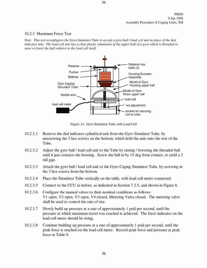
10.2.3 Maximum Force Test
Note: This test reconfigures the Gyro Simulator Tube to accept a gyro ball / load cell unit in place of the dial
indicator unit. The load cell unit has a clear plastic simulation of the upper half of a gyro which is threaded to
raise or lower the ball relative to the load cell itself.
Retainer
Pusher
BellowsHousing/Actuator Assembly
Retainer hex bolts (3)
Model of Gyro Housing upper half
Gyro Caging Simulator Tube
Model of Gyro Rotor upper half
screws for securing unit to tube
nut adjustment
flexible wire
load cell
load cell meter
Figure 14. Gyro Simulator Tube with Load Cell
10.2.3.1 Remove the dial indicator cylindrical unit from the Gyro Simulator Tube, by
unscrewing the 3 hex screws on the bottom, which hold the unit onto the rest of the
Tube.
10.2.3.2 Adjust the gyro ball / load cell unit to the Tube by raising / lowering the threaded ball
until it just contacts the housing. Screw the ball in by 15 deg from contact, to yield a 2
mil gap.
10.2.3.3 Attach the gyro ball / load cell unit to the Gyro Caging Simulator Tube, by screwing in
the 3 hex screws from the bottom.
10.2.3.4 Place the Simulator Tube vertically on the table, with load cell meter connected.
10.2.3.5 Connect to the CCU as before, as indicated in Section 7.2.5, and shown in Figure 6.
10.2.3.6 Configure the manual valves to their nominal conditions as follows:
V1 open, V2 open, V3 open, V4 closed, Metering Valve closed. The metering valve
shall be used to control the rate of rise.
10.2.3.7 Slowly build up pressure at a rate of approximately 1 psid per second, until the
pressure at which maximum travel was reached is achieved. The force indicator on the
load cell meter should be rising.
10.2.3.8 Continue building up pressure at a rate of approximately 1 psid per second, until the
peak force is reached on the load cell meter. Record peak force and pressure at peak
force in Table 9.
P0050
9 Jan 1998
Assembly Procedure of Caging Units, SM
37
37
10.2.3.9 After completing reading, close off pressure at V2 and open V4 to vent to one
atmosphere.
10.2.3.10 Repeat the peak force reading by repeating steps 10.2.3.6 through 10.2.3.9.
If the force does not meet requirement, reject this unit at this point. Indicate in Table
9.
10.2.3.11 Replace the Housing / Actuator Assembly with a new one, by following the
disconnect/connect steps described in Sections 7.2.10 through 7.2.12.
10.2.3.12 Repeat 10.2.3.6 through 10.2.3.11 until all Housing/Actuator Assemblies are tested for
maximum force.
10.2.3.13 Upon completion of all pressure tests, epoxy bond the Keeper to the Housing,
following Epoxy Bond Procedure P0355. Let cure according to this procedure.
Completed: ___________________________________ date:
Responsible Engineer
Discrepancies if any:
P0050
9 Jan 1998
Assembly Procedure of Caging Units, SM
38
38
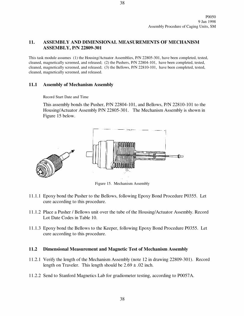
11. ASSEMBLY AND DIMENSIONAL MEASUREMENTS OF MECHANISM
ASSEMBLY, P/N 22809-301
This task module assumes (1) the Housing/Actuator Assemblies, P/N 22805-301, have been completed, tested,
cleaned, magnetically screened, and released; (2) the Pushers, P/N 22804-101, have been completed, tested,
cleaned, magnetically screened, and released; (3) the Bellows, P/N 22810-101, have been completed, tested,
cleaned, magnetically screened, and released.
11.1 Assembly of Mechanism Assembly
Record Start Date and Time
This assembly bonds the Pusher, P/N 22804-101, and Bellows, P/N 22810-101 to the
Housing/Actuator Assembly P/N 22805-301. The Mechanism Assembly is shown in
Figure 15 below.
Figure 15. Mechanism Assembly
11.1.1 Epoxy bond the Pusher to the Bellows, following Epoxy Bond Procedure P0355. Let
cure according to this procedure.
11.1.2 Place a Pusher / Bellows unit over the tube of the Housing/Actuator Assembly. Record
Lot Date Codes in Table 10.
11.1.3 Epoxy bond the Bellows to the Keeper, following Epoxy Bond Procedure P0355. Let
cure according to this procedure.
11.2 Dimensional Measurement and Magnetic Test of Mechanism Assembly
11.2.1 Verify the length of the Mechanism Assembly (note 12 in drawing 22809-301). Record
length on Traveler. This length should be 2.69 ± .02 inch.
11.2.2 Send to Stanford Magnetics Lab for gradiometer testing, according to P0057A.
P0050
9 Jan 1998
Assembly Procedure of Caging Units, SM
39
39
Housing /Actuator
Assembly
(P/N 22805-301)
Serial Number
Pusher
(P/N 22804-101)
Lot Date Code
Bellows
(P/N 22810-101)
Lot Date Code
Retainer
(P/N 22897-101)
Lot Date Code
Table 10. Serial Numbers, Lot Date Code
of Housing /Actuator Assembly, Pusher, Bellows, and Retainer
NOTE: The Mechanism Assembly and Caging Subassembly Serial Numbers are identical to the
Housing/Actuator Serial Numbers, after completion of this assembly.
Completed: ___________________________________ date:
Responsible Engineer
Discrepancies if any:
P0050
9 Jan 1998
Assembly Procedure of Caging Units, SM
40
40
12. ASSEMBLY OF CAGING SUBASSEMBLY, P/N 23190-301
This task module assumes (1) the Mechanism Assemblies, P/N 22809-301, have been completed and tested; (2)
the Retainers, P/N 22897-101, have been completed, cleaned, magnetically screened, etched, and released.
12.1 Assembly of Caging Subssembly
Record Start Date and Time
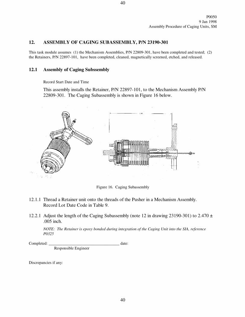
This assembly installs the Retainer, P/N 22897-101, to the Mechanism Assembly P/N
22809-301. The Caging Subassembly is shown in Figure 16 below.
Figure 16. Caging Subassembly
12.1.1 Thread a Retainer unit onto the threads of the Pusher in a Mechanism Assembly.
Record Lot Date Code in Table 9.
12.2.1 Adjust the length of the Caging Subassembly (note 12 in drawing 23190-301) to 2.470 ±
.005 inch.
NOTE: The Retainer is epoxy bonded during integration of the Caging Unit into the SIA, reference
P0325
Completed: ___________________________________ date:
Responsible Engineer
Discrepancies if any:
P0050
9 Jan 1998
Assembly Procedure of Caging Units, SM
41
41
13. ASSEMBLY AND TEST OF TUBING ASSEMBLY, CAGING JUMPER LINE,
P/N 23188-201
13.1 Assembly of Tubing Assembly, Caging Jumper Line
This task module takes place in Stanford’s HEPL building Tube Shop, Rm 141. It assumes the Tubing
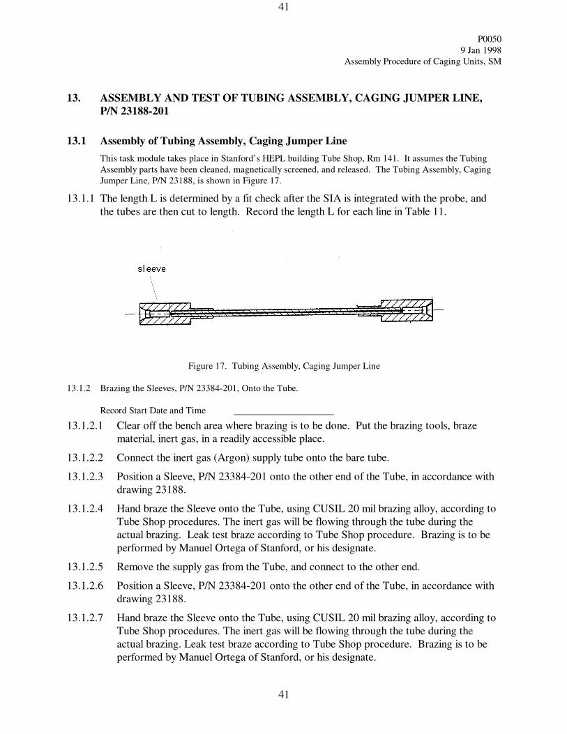
Assembly parts have been cleaned, magnetically screened, and released. The Tubing Assembly, Caging
Jumper Line, P/N 23188, is shown in Figure 17.
13.1.1 The length L is determined by a fit check after the SIA is integrated with the probe, and
the tubes are then cut to length. Record the length L for each line in Table 11.
Figure 17. Tubing Assembly, Caging Jumper Line
13.1.2 Brazing the Sleeves, P/N 23384-201, Onto the Tube.
Record Start Date and Time
13.1.2.1 Clear off the bench area where brazing is to be done. Put the brazing tools, braze
material, inert gas, in a readily accessible place.
13.1.2.2 Connect the inert gas (Argon) supply tube onto the bare tube.
13.1.2.3 Position a Sleeve, P/N 23384-201 onto the other end of the Tube, in accordance with
drawing 23188.
13.1.2.4 Hand braze the Sleeve onto the Tube, using CUSIL 20 mil brazing alloy, according to
Tube Shop procedures. The inert gas will be flowing through the tube during the
actual brazing. Leak test braze according to Tube Shop procedure. Brazing is to be
performed by Manuel Ortega of Stanford, or his designate.
13.1.2.5 Remove the supply gas from the Tube, and connect to the other end.
13.1.2.6 Position a Sleeve, P/N 23384-201 onto the other end of the Tube, in accordance with
drawing 23188.
13.1.2.7 Hand braze the Sleeve onto the Tube, using CUSIL 20 mil brazing alloy, according to
Tube Shop procedures. The inert gas will be flowing through the tube during the
actual brazing. Leak test braze according to Tube Shop procedure. Brazing is to be
performed by Manuel Ortega of Stanford, or his designate.
P0050
9 Jan 1998
Assembly Procedure of Caging Units, SM
42
42
13.1.2.8 Clean subassembly with TF spray according to procedure P0059, bag, and store in
numbered compartment.
13.1.2.9 Repeat 13.1.2.1 through 13.1.2.8 until 16 assemblies are completed.
13.2 LN2 Dip, Leak Test, and Mag Test of Tubing Assembly, Caging Jumper Line
The LN2 dip procedure takes place at Stanford HEPL, Class 1000 Clean Room bench. The Leak Test will
be done in the Class 1000 Clean Room.
Record Start Date and Time
13.2.1 Prepare a LN2 dewar flask of height sufficient to hold the entire assembly in the liquid,
cold vapor, and warm vapor, and fill to a depth of approximately 10 inches with Liquid
Nitrogen.
13.2.2 Prepare a tack pulley arrangement above the bench, such that a line can be plumbed into
the dewar flask.
13.2.3 Prepare a monofilament nylon tie line to support the Tubing Assembly such that there are
markers visible above the flask, which indicate the assembly is (a) in the liquid, (b) in the
cold vapor, and (c) in the warm vapor, when the marker is at the pulley location. See
P0063 for further details.
13.2.4 Thermal cycle the unit according to Cryo Dip Procedure P0063.
13.2.5 After thermal cycling, store in clean numbered storage compartments. Repeat cryo-dip
procedure for all candidate units, and store in numbered compartments.
13.2.6 After thermal cycling all candidate units, perform vacuum leak test of each unit according
to P0054. Record leak rate in Table 11.
13.2.7 Clean subassembly with TF spray according to P0059, bag, and store in numbered
compartment.
13.2.8 Send to Stanford Magnetics Lab for magnetic testing, according to P0057A.
P0050
9 Jan 1998
Assembly Procedure of Caging Units, SM
43
43
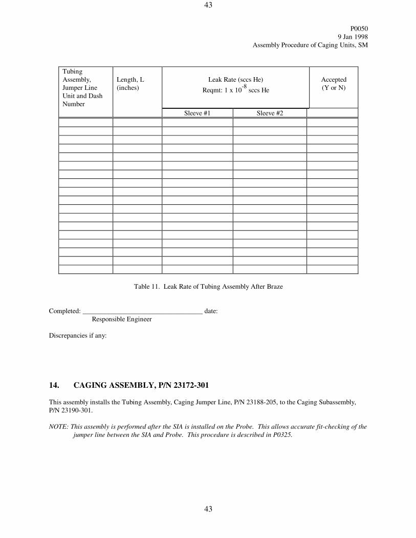
Tubing
Assembly,
Jumper Line
Unit and Dash
Number
Length, L
(inches)
Leak Rate (sccs He)
Reqmt: 1 x 10⁻⁸
sccs He
Accepted
(Y or N)
Sleeve #1 Sleeve #2
Table 11. Leak Rate of Tubing Assembly After Braze
Completed: ___________________________________ date:
Responsible Engineer
Discrepancies if any:
14. CAGING ASSEMBLY, P/N 23172-301
This assembly installs the Tubing Assembly, Caging Jumper Line, P/N 23188-205, to the Caging Subassembly,
P/N 23190-301.
NOTE: This assembly is performed after the SIA is installed on the Probe. This allows accurate fit-checking of the
jumper line between the SIA and Probe. This procedure is described in P0325.
P0050
9 Jan 1998
Assembly Procedure of Caging Units, SM
44
44
15. PROCEDURE COMPLETION
The results obtained in the performance of this procedure are acceptable.
Responsible Engineer ____________________________ Date ______________
Hardware Manager: __________________________ Date ______________
The information obtained under this assembly and test procedure is as represented and the documentation is
complete and correct.
Quality Assurance ____________________________________ Date _____________
16. DATA BASE ENTRY
The following data shall be entered into the GP-B Data Base:
1) Name, number and revision of this procedure
2) Date of successful completion of procedure.


![From Caging to Grasping - Robotics Institutestretching caging proposed in recent algorithmic approaches to the two-finger caging problem [4], [8]. Squeezing and stretching caging](https://img.pdfslide.us/doc/110x75/5f4d528ec252083ae648bee7/from-caging-to-grasping-robotics-institute-stretching-caging-proposed-in-recent.jpg)