Embed Size (px)
Citation preview

WEBSITE
www.reidlifting.com
Assembly & Operation

No. 1 in lightweight, portable, safe lifting solutions
2
CONTENTS
INTRODUCTION
CORRECT OPERATION• Intended Use
• Inspection Prior to Initial Operation
• Inspection Before Starting Work
• Maximum Capacity
NOTES FOR CORRECT USAGE• Warning
• Attaching the Load
• Temperature Range
• Regulations
INSPECTION/MAINTENANCE • Regular Inspections
• Maintenance/Repair
• Storage and Transportation
SOCKETS• Socket Installation
• Verifying the Installation
MARKING
ATEX• ATEX - Classification
• ATEX - Identification
• ATEX - Spark Formation
• ATEX - Static Electricity
• ATEX - Inspection, Maintenance & Repair
IRATA
LANGUAGE
ASSEMBLY INSTRUCTIONS• T-DAVIT - Type W
• T-DAVIT - Type VW
• T-DAVIT - Type T
QUALITY & SAFETY• Accreditations
TESTING
PRODUCT IPR
INSPECTION RECORD

Tel: +44 (0)1291 620796 www.reidlifting.com
INTRODUCTION
All users must read these operating instructions carefully prior to the initial operation. These instructions are intended to acquaint the user with the T-DAVIT and enable him/her to use it to the full extent of its intended capabilities.
The operating instructions contain important information on how to handle the T-DAVIT in a safe, correct and economic manner. Acting in accordance with these instructions helps to avoid dangers, reduce repair costs and down time and to increase reliability and lifetime of the davit.
Anyone involved in doing any of the following work with the T-DAVIT must read the operation instructions and act accordingly:
• Operation, including preparation, trouble shooting during operation and cleaning
• Maintenance, inspection, repair
• Transport
Apart from the operating guide, health & safety and accident prevention act valid for the respective country and area where the equipment is used, the commonly accepted regulations for safe and professional work must be adhered to.
It is incumbent on the user or instigator of work with the equipment that all users have suitable medical and physical capabilities. Likewise the competent person should ensure there is a rescue plan in place in the event of an emergency that could occur during the work.
N.B. This document should form an element of the overriding Risk Assessment and Method Statement required for each lift.

No. 1 in lightweight, portable, safe lifting solutions
4
Before starting work inspect the assembly and all load-bearing components for visual defects.
Check the integrity of all profiles for denting and bolt holes for wear and elongation. Ensure that the overall working load limit (WLL) is adhered to – following the necessary Risk Assessment and Method Statement.
Maximum Capacity
The T-DAVIT is designed to lift and lower loads up to its rated capacity. The capacity indicated on the product is the maximum working load limit (WLL) or safe working load (SWL) which must not be exceeded (definition is country dependent).
When being used as a personnel lifting anchor the user must use a body harness and retractable device or shock absorber that complies with EN355, ANSI Z359.6-09 or CSA Z259.16-04 (whichever is relevant) that limits the maximum allowed force (M.A.F.) to 6kN. Winches used with the T-DAVIT should comply to EN1496:2006 or equivalent.
Only ONE person/load may be attached to the T-DAVIT structure in accordance with the WLLs.
If the T-DAVIT is to be used for personnel winching the WLLs must be observed. It is possible for the T-DAVIT to have a WLL higher than could be used with a fall arrest device. This is for situations where the structure is to be used as an anchor for lifting persons that have no possibility of falling through a free distance or when drafting out a rescue plan and should only be carried out following a comprehensive risk assessment.
N.B. If winching personnel a secondary line/fall arrest unit may also be required.
While the T-DAVIT will have the capabilities stated on the product it is only one part of a fall arrest system which is only as strong as its lowest rated component. Each lift must be properly planned and all weights clearly known along with the WLLs and constraints of all fall arrest system devices.
In the event of simultaneous goods and personnel combined lifting or when being used as a fall arrest system in sub-zero AND wet conditions contact the supplier as capacities may be reduced.
Only a chain hoist up to a capacity of 1000kg may be used with the davit. The structure has been designed such that the weight of a chain block can be neglected,
CORRECT OPERATIONIntended Use
The T-DAVIT range is intended to be used for the lifting of goods, the lifting of persons or for providing a safety anchor for the prevention of falls.
N.B. Not all T-DAVITs are certified for the lifting of personnel! If unsure whether your product is designed for the lifting of persons consult your serial label, see Marking, or Certificate of Test which will indicate the WLL for persons if applicable.
We recommend that the device is dedicated to either goods or personnel use and where reasonably practicable to avoid using the structure for both.
T-DAVIT S & W up to 1600mm radius are suitable for Rope Access. Both devices have been tested to 15KN static load as per test requirements of IRATA International Code of Practice (ICOP).
N.B. Standard socket extensions are suitable for Rope Access when used with a maximum radius of 1200mm.
Inspection Prior to Initial Operation
Each T-DAVIT must be inspected prior to initial operation by a competent person. The inspection is visual and functional and shall establish that the structure is safe and has not been damaged by incorrect assembly, transport or storage. The inspection should particularly concentrate on:
• Dents or indentations on the kingpin, beam and column surfaces
• Straightness of beam and column sections;
• Elongation of the beam holes or signs that beam inserts have become loose
• The condition of the beam clevis pins for damage and straightness
• Damage to the attachments
The above list is not exhaustive. Inspections are instigated by the user.
Inspection Before Starting Work
The inspection procedure requires that a valid inspection/test certificate has been submitted to and checked by the user.

Tel: +44 (0)1291 620796 www.reidlifting.com
• Lift only when load chain/rope forms a vertical line between load and lifting shackle used
• Do not allow the load to swing
• When lifting keep the load as low to the ground as possible
• If the T-DAVIT is to be used in special atmospheres contact your supplier
• When using the T-DAVIT as a fall arrest anchor the required clearance of the fall arrest device should be considered - refer to the device’s Operations and Maintenance manual
• NEVER walk away from structure whilst connected to the equipment i.e. connected by a fall arrest block or winch
• Before the T-DAVIT is used consideration must be given to the potential effects of the ropes running over sharp edges, chemical reagents, electrical conductivity, cutting, abrasion, climatic exposure and the effect of offset forces as a result of pendulum falls
however if using a device with a significant weight it should be included into the WLL.
In the event of using a lifting device other than a manual chain hoist particular attention must be paid to the dynamic effects induced into the structure and it may be required to reduce the WLL of the structure. If in doubt contact your REID Lifting representative.
N.B. Maximum radius would be achieved when the davit is under approximately 75% of the Working Load Limit.
NOTES FOR CORRECT USAGE
• We recommend the use of load-sensing or overload protection devices on all lifts
• The Risk Assessment & Method Statement must consider additional loading resulting from any “wet lift” or ‘break-out force’ situations
• Ensure suitable winches and connection plates are used for all applications
• Due care and attention should be practiced when transporting and storing the product to avoid damage
• Do not throw the product or its components down or stack items on top of it. Always place properly on the ground to avoid damaging the equipment
• Assemble only as instructed (ensure all bolts are present and fitted correctly as per instructions)
• We recommend that gloves should be worn when using this equipment
• Do not assemble davit in non-approved sockets
• Do not use the davit if the kingpin shaft is not seated correctly in the socket
• Do not use the davit if it does not rotate freely in the bearing or the bottom flange is fouled in any way, preventing free rotation of the davit
• Set up the product in its mounting socket ensuring that it is a safe location and there is no risk of falling into the hazard
• Persons are forbidden to walk or stand in dangerous areas
• Attach the load only to the lifting points on the beam or the lifeline/winch-line
DisclaimerAll REID Lifting sockets & extensions have been designed, developed and tested for safe use with REID equipment and form a key part of the integrity of the total system.
• All sockets have a working load limit (WLL) based on the maximum radius setting of the davit, and the socket installation and verification tests performed
• All sockets are supplied in galvanised mild steel, stainless steel (316L grade, passivated) or aluminium
• Sockets can be powder coated upon request e.g. Yellow for trip hazard warning
Should non-standard third party sockets be used, REID Lifting’s Declaration of Conformity & Incorporation on the products is negated. i.e. The system becomes the responsibility of the client.

No. 1 in lightweight, portable, safe lifting solutions
6
Warning
• The equipment shall not be used outside its limitations, or for any purpose other than that for which it is intended
• Do not allow personnel to pass under a suspended load
• NEVER leave a suspended load unattended.
• The T-DAVIT can only be used for lifting or arresting the fall of ONE person
• It is NOT recommended to mix the use of the T-DAVIT with personnel and goods lifting concurrently
• Be aware of hazards when setting up/setting down
• It is essential for safety that the T-DAVIT is withdrawn from use immediately should:
1. Any doubt arise about its condition for safe use
Or
2. It has been used to arrest a fall and not be used again until confirmed in writing by a competent person that it is acceptable to do so
Attaching the Load
The operator must ensure that the load is attached in a manner that does not expose him or other personnel to danger by the hoist, chain(s) or the load.
Temperature Range
The T-DAVIT can be operated in ambient dry temperatures between -20° and +55°C (-4°F to 131°F). Consult your supplier in case of extreme working conditions.
If used in sub-zero and wet conditions, the performance may be affected.
Regulations
The T-DAVIT complies with the following regulations:
PPE Regulation (EU) 2016/425, Machinery Directive 2006/42/EC, ATEX Directive 2014/34/EU, The Provision and Use of Work Equipment Regulations 1998 (S.I. 1998 No. 2306), EN795:2012, The Lifting Operations and Lifting Equipment Regulations 1998 (S.I. 1998 No. 2307). In conformity with AS/NZS 5532:2013*. The safety regulations of the respective country for using manual lifting equipment must be strictly adhered to.
* Applies to radius up to 1600mm
INSPECTION/MAINTENANCERegular Inspections
To ensure that the structure remains in safe working order it must be subjected to thorough periodic inspections by a competent person. Inspections are to be 6 monthly if used for the lifting of persons or 12 monthly otherwise unless adverse working conditions or profile of use dictate shorter periods. The components of the structure are to be inspected for damage, wear, corrosion or other irregularities. To check for worn parts it may be necessary to disassemble the structure. Particular attention should be paid to the areas of the structure described under Inspection Prior to Initial Operation.
Repairs should only be carried out by an approved specialist workshop that uses original spare parts. It is recommended that once inspected the device is marked with the date of next inspection.
Inspections are instigated by the user. If detailed information is required on inspection and test criteria, please refer to your supplier’s technical department.
Please refer to page 23 for the equipment Inspection Record.
If using the T-DAVIT in explosive atmospheres see additional section titled ATEX.

Tel: +44 (0)1291 620796 www.reidlifting.com
Maintenance/Repair
In order to ensure correct operation, not only the operating instructions, but also the conditions for inspection and maintenance must be complied with. If defects are found stop using the T-DAVIT immediately.
No alterations or additions to the equipment should be made without the written consent of the manufacturer. Any repair shall only be carried out in accordance with the manufacturer’s procedures.
It is recommended to maintain the equipment in a clean and dry manner. Cleaning is suggested using a sponge or cloth with warm, soapy water (using diluted domestic washing up liquid), rinsing and allowing to dry.
Storage and Transportation
The T-DAVIT and its accessories are to be stored and transported in the bags provided.
When transporting the components the user must take note of the manual handling considerations.
SOCKETSThe T-DAVIT structure needs to be anchored to a surface/foundation capable of withstanding the applicable loading. The davit can be supplied with one of the sockets specified below (only sockets supplied by REID Lifting are approved to be used with the T-DAVIT):
• The Top Mount socket is for use on flat horizontal surfaces. It can be installed onto concrete using resin anchors or into steel work using bolts
• The Side Mount socket can be installed using resin anchors or mechanical anchors
• The Bridge Mount socket is for mounting in steel work
• The Cast and Resin Bonded sockets can be cast into new concrete or resin bonded into existing concrete
Socket Installation
Depending upon the socket type there are multiple ways that installation can be achieved. When using bolts they are to be minimum grade 8.8 BZP or, if stainless, grade A4, or equivalent.
When installing the socket it is important to ensure that the top face is as level as possible, with installation being not more than 3 degrees misaligned from the horizontal.
Socket installation should only be carried out by a competent person. If specifying the anchors, resin, fasteners or any combination of the afore-mentioned, it is essential that the competent person is of ability to specify an installation that is safe for use. If in any doubt about the calculation of loads contact your REID Lifting representative.
Verifying the Installation
REID Lifting strongly recommends testing the installation of the socket before initial use; especially when using resin bonded anchors.
When verifying the installation we recommend that it is tested to a maximum force of 6kN at the devices maximum radius if used for the lifting of personnel. If only used for the lifting of goods we recommend testing to no greater than 125% of the goods’ WLL at its maximum radius. All tests should be carried out in all anticipated worst case loading directions, sustained for a duration of 3 minutes.
If unable to test the installation as a whole then each anchor can be isolated and tested individually applying the applicable loading, i.e. tension and/or shear loads. For clarification on the loads contact your equipment supplier.
If an installation differs from the sockets referred to above or to that specified by your supplier then the competent person must verify by calculation that the installation can withstand:
• For personnel, 12kN at the device’s maximum radius in all anticipated worst case loading directions, but do not test to more than 6kN at the device’s maximum radius
Top Mount
Side Mount
Bridge Mount
Cast & Resin Bonded
No. 1 in lightweight, portable, safe lifting solutions
8
• For lifting of goods, 150% of the goods WLL at the device’s maximum radius in all anticipated worst case loading directions, but not test to more than 125% of the goods WLL at the device’s maximum radius
If required a sacrificial anchor may need to be installed to verify the installation has the ultimate capacities required.
Following initial socket installation verification tests we do not recommend overload tests for the socket or davit and suggest thorough visual examination only. If the client feels that as a result of a visual examination that a load test is appropriate, we would recommend a 100% load test and certainly no greater than 125%.
MARKINGThe serial labels indicate:
• The product description
• The product identification number
• The product’s unique serial number
• The goods’ working load limit (WLL) of the device
• The year of manufacture
• The standards to which the device is approved (only applicable when rated for the lifting of persons)
• The ATEX rating of the product (if applicable) - see ATEX section
• CE 0088: CE mark plus notified body number (currently LRQA) who are responsible for monitoring REID Lifting’s quality control system in accordance with Modlue D of the PPE Regulation (only applicable when rated for the lifting of persons otherwise CE just stated).
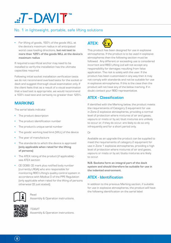
ATEX:
This product has been designed for use in explosive atmospheres. If the product is to be used in explosive atmospheres then the following section must be followed. Any different or exceeding use is considered incorrect and REID Lifting Ltd will not accept any responsibility for damages resulting from false application. The risk is solely with the user. If the product has been customised in any way then it may not comply with standards and not be suitable for use in explosive atmospheres. If this is the case then the product will not have any of the below marking. If in doubt contact your REID representative.
ATEX - Classification
If identified with the Marking below, the product meets the requirements of Category 3 equipment for use in Zone 2 explosive atmospheres, providing a normal level of protection where mixtures of air and gases, vapours or mists or by air/dust mixtures are unlikely to occur or, if they do occur, are likely to do so only infrequently and for a short period only.
Or
Available as an upgrade the product can be supplied to meet the requirements of category 2 equipment for use in Zone 1 explosive atmospheres, providing a high level of protection where mixtures of air and gases, vapours or mists or by air/dusts mixtures are likely to occur.
N.B. Sockets form an integral part of the davit system and should therefore be suitable for use in the indented environment.
ATEX - Identification
In addition to the previous Marking section, if suitable for use in explosive atmospheres, the product will have the following identification on the serial label:
T-DAVIT Assembly & Operation instructions.
Read Assembly & Operation instructions.

Tel: +44 (0)1291 620796 www.reidlifting.com
As Standard for Zone 2 Environments:
II 3 GD T6
Identification for protection against explosions
II: Unit group II – non-mining application3: Category 3 – Normal safety for use in Zone 2
GD: For use in gas (G) & dust (D) atmospheresT6:Temperature class – Max 85°C
Or
As an Upgrade for use in Zone 1 Environments:
II 2 GD T6
Identification for protection against explosions
II: Unit group II – non-mining application2: Category 2 – High safety for use in Zone 1
GD: For use in gas (G) & dust (D) atmospheresT6:Temperature class – Max 85°C
ATEX - Spark Formation
Increased danger of ignition may emanate from clashing of special material pairings. These are non-corrosion resistant steel or cast iron against aluminium, magnesium or pertinent alloys. This applies especially in case of rust or surface rust.
When assembling the product and inserting fastening components; they must be clear of rust and debris of any kind. Care must be taken to ensure the product is handled in a suitable manner and is never thrown, and always placed, onto the ground.
ATEX - Static Electricity
For Zone 2 applications, static electricity has been identified as potential for build-up, leading to an incendive spark. Although the risk of such ignition is unlikely, the structure must have a clear route to earth, which must be considered when installing the sockets for mounting the structure. These sockets should be in direct contact with the ground and there should be no membrane separating the socket from the ground.
If an isolating membrane is to be used, an earthing path must be provided. If the structure is to be used in a larger socket with a nylon sleeve the davit will have to be earthed using a 4mm earthing cable attached to a convenient location on a metallic part of the structure.
ATEX - Inspection, Maintenance & Repair If using the davit in explosive atmospheres, in addition to the Regular Inspection/Maintenance information found on page 6, these additional instructions should be followed.
Inspections shall be instigated by the user and occur at least 6 monthly or sooner if adverse operating conditions or profile of use dictate shorter periods. Inspections and maintenance shall be carried out at a safe distance away from an explosive atmosphere.
Special attention should be given to dust deposits on the structure, especially in areas where the profiles come into contact and should be wiped clean and care taken not to apply materials that could create electrostatic charging. Additionally the kingpin should be checked to ensure it rotates freely and the lower bearing must be ensured to be fixed to the structure with no possibility of a build-up of debris between the contact surfaces.
The structure is predominantly constructed from aluminium which will not rust. However there are steel components used throughout. These are the fasteners, shackles and sockets. Where there is sign of any rust deposits on the aluminium structure it should be wiped clean as above and where there is sign of rust on a steel component, then that component should be removed from use and the structure not used until a replacement is fitted.
IRATAT-DAVIT S & W up to 1600mm radius are suitable for Rope Access. Both devices have been tested to 15KN static load as per test requirements of IRATA International Code of Practice (ICOP).
N.B. Standard socket extensions are suitable for Rope Access when used with a maximum radius of 1200mm.

No. 1 in lightweight, portable, safe lifting solutions
10
LANGUAGE It is essential for the safety of the user that if this product is re-sold outside the original country of destination the reseller shall provide instructions for use, maintenance, for periodic examination and for repair in the language of the country in which the product is to be used.

Tel: +44 (0)1291 620796 www.reidlifting.com
Gloves Hard hatProtective footwear
T-DAVIT - Type WASSEMBLY INSTRUCTIONS
N.B. Appropriate PPE should be worn:
The T-DAVIT and its constituent components are described in the image below. The use of a socket extension is optional and the socket type may vary between a Top Mount, Side Mount, Bridge Mount, Cast In or Resin Bonded depending on application. The T-DAVIT shown is a winched version but an unwinched variant is also available.
N.B. No tools are required for assembly.
Socket Extension (Optional)
(500, 800, 1100mm)
Socket
(Top Mount shown - others available)
ColumnWinch
Cheek Plate
Rear Sheave
Shackle
Shackle/Winch Plate
Beam
Front Sheave
Lifeline/Winch Line

No. 1 in lightweight, portable, safe lifting solutions
12
2. The T-DAVIT has the option to install a winch on the column as illustrated in the image. Ensure the clevis pins are secured in place using the R-clips.
N.B. Winch is for illustration only; winch installation may differ. Contact your REID sales representative for more details.
3. Play out sufficient rope to thread through the length of beam whilst at ground level. Thread the rope over the sheaves and through the beam as shown.
The rope retaining pins need to be removed to fit the rope in the sheave then reinserted ensuring they are secure.
1. Insert the T-DAVIT into the socket as shown.
N.B. Top Mount socket shown.
N.B. If using a socket extension, install first. The use of a ladder may be required.
Assembling the WinchAssembling the T-DAVIT

Tel: +44 (0)1291 620796 www.reidlifting.com
6. Rotate the beam as illustrated.
N.B. In some circumstances the winch can be used to rotate the beam in line for the pin insertion.
7. Insert the clevis pin to take the weight of the beam and secure the pin with the R-clip.
For disassembly, reverse steps 1-7.
4. The T-DAVIT beam can be assembled at 2 positions as shown. Ensure the correct set-up is chosen at this stage.
5. Present the beam to the chosen location and insert the clevis pin. Secure the pin with retaining R-clip.
N.B. If a socket extension is being used, the use of a ladder may be required.
Assembling the Beam
Position B
Position A
Position B
Position A
No. 1 in lightweight, portable, safe lifting solutions
14
Gloves Hard hatProtective footwear
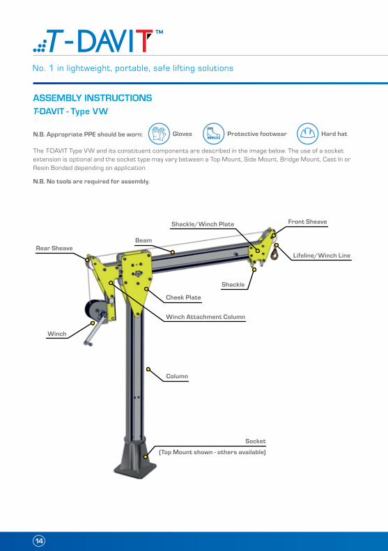
T-DAVIT - Type VWASSEMBLY INSTRUCTIONS
N.B. Appropriate PPE should be worn:
The T-DAVIT Type VW and its constituent components are described in the image below. The use of a socket extension is optional and the socket type may vary between a Top Mount, Side Mount, Bridge Mount, Cast In or Resin Bonded depending on application.
N.B. No tools are required for assembly.
Column
Winch
Cheek Plate
Winch Attachment Column
Rear Sheave
Shackle
Shackle/Winch Plate
Beam
Front Sheave
Lifeline/Winch Line
Socket
(Top Mount shown - others available)

Tel: +44 (0)1291 620796 www.reidlifting.com
1. Insert T-DAVIT column into socket.
N.B. Top Mount socket shown.
N.B. If using a socket extension, install first. The use of a ladder may be required.
2. Place the beam between rollers and slide it in.
3. Insert and secure bolt and spacer as shown.
This will act as a stopper to prevent the beam from disengaging.
4. Place winch attachment column to the beam as shown.
Assembling the T-DAVIT Type VW

No. 1 in lightweight, portable, safe lifting solutions
16
6. Place the winch and bracket in position.
7. Secure assembly with the pins supplied. 8. Thread the rope over the sheaves. The rope retaining pins need to be removed before fitting the rope.
5. Secure attachment with the nuts and bolts supplied.

Tel: +44 (0)1291 620796 www.reidlifting.com
9. Reinsert pins ensuring they are secure.
Please refer to the Operating manual of the winch before use.

No. 1 in lightweight, portable, safe lifting solutions
18
Gloves Protective footwear
T-DAVIT - Type TASSEMBLY INSTRUCTIONS
N.B. Appropriate PPE should be worn:
The T-DAVIT Type T and its constituent components are described in the image below. The use of a socket extension is optional and the socket type may vary between a Top Mount, Side Mount, Bridge Mount, Cast In or Resin Bonded depending on application.
N.B. No tools are required for assembly.
Hard hat
Column
Cheek Plate
Trolley
Beam
Socket
(Top Mount shown - others available)

Tel: +44 (0)1291 620796 www.reidlifting.com
1. Remove bolt and spacer at the front of the beam
Assembling the T-DAVIT Type T
2. Thread beam trolley over the end of the beam
3. Lock trolley with friction brake at approximately centre position
4. Reinsert bolt and spacer ensuring they are secure.

No. 1 in lightweight, portable, safe lifting solutions
20
5. Insert T-DAVIT column into the socket 6. Present the beam to the column and insert clevis pin to take the weight of the beam
7. Secure the pin with retaining R-clip 8. Rotate the beam as illustrated

Tel: +44 (0)1291 620796 www.reidlifting.com
9. Insert rear clevis pin 10. Secure the pin with retaining R-clip
11. Release trolley brake and use the hand chain to move the trolley along the beam.

22
ACCREDITATIONS
Quality and safety are key themes throughout this document and the REID Lifting ethos. It is with this in mind that we have undertaken external accreditations to ensure we stay focused on what is important to our clients and users, and ahead of market trends and developments.
REID Lifting is continuously audited by Lloyds Register Quality Assurance (LRQA) (CE body no. 0088) for approval of its Integrated Management System combining quality systems management, environmental issues and the health and safety practices within the company.
• ISO 9001:2015 - Specifies requirements for a quality management system for any organisation that needs to demonstrate its ability to consistently provide products that meet customer and applicable regulatory requirements and aims to enhance customer satisfaction.
• ISO 14001:2015 - Specifies the requirements for implementing environmental management systems throughout all areas of the company.
• OHSAS 18001:2007 - Occupational health and safety management system.
• LEEA Membership - REID Lifting is a full member of the Lifting Equipment Engineers Association (LEEA membership 000897). REID Lifting conforms to the main aims of the association which is to achieve the highest standards of quality and integrity in the operations of members. Entry qualifications are demanding and strictly enforced through technical audits based on the Technical Requirements for Members.
• IRATA - REID Lifting is an associate member of the Industrial Rope Access Trade Association (IRATA International membership number 148). REID Lifting works in accordance with the IRATA Code of Practice, by doing so, contributes to promote the development of safe systems.
Conformité Européenne (CE)REID Lifting’s products have been designed, tested and approved (as appropriate) by the Conformité Européenne. This certifies that REID Lifting’s products meet the demands of the European Directives and Regulations regarding health and safety requirements. The EC type-examination for this device has been carried out by SGS United Kingdom Ltd, 202b, Worle Parkway, Westonsuper-Mare, BS22 6WA, United Kingdom (CE body no.0120) in accordance with Module B of the PPE Regulation. The EC quality assurance system for this device has been carried out by Lloyd’s Register Quality Assurance Limited, 1, Trinity Park, Bickenhill Lane, Birmingham B37 7ES, United Kingdom (CE body no. 0088) in accordance with Module D PPE Regulation (EU) 2016/425.
The Queen’s Award for EnterpriseREID Lifting has been awarded this prestigious award on four occasions for design, development and sale of lightweight, portable and safe lifting solutions.
• Innovation category 2006 and 2013
• International Trade 2013 and 2018
TESTINGTesting and Technical File review are integral parts of our design and manufacturing process. External verification of products is undertaken where appropriate, using government approved Notified Bodies.
All products have been thoroughly type tested at UKAS accredited laboratories. Each system is supplied with a certificate of conformance and individual record of thorough examination or test.
Full product design and development Technical Files are available for inspection.
PRODUCT IPRIntellectual property rights apply to all REID Lifting Ltd products. There are patents in place, or pending, for:
PORTA-GANTRY | PORTA-GANTRY RAPIDE | PORTA-DAVIT QUANTUM | T-DAVIT
All product names are trade-marks of REID Lifting Ltd:
PORTA-GANTRY | PORTA-GANTRY RAPIDE | PORTA-DAVIT | PORTA-BASE | T-DAVIT | PORTA-QUAD
THE QUEEN’S AWARDS FOR ENTERPRISE:
INTERNATIONAL TRADE2018
QUALITY & SAFETY
E&OE

Tel: +44 (0)1291 620796 www.reidlifting.com
* Insert data from serial numbers found on product into table below
ABCD
INSPECTION RECORD
INSPECTION
Product number(s)* A
Serial number(s)* B
WLL* C
Year of manufacture* D
Name of user
Date of purchase
Date of first use
Periodic Examination and Repair History
Date Inspected by Pass/Fail Comments

24
ASSEMBLY & OPERATION MANUAL
t
f
e
w
t
t
e
e
w
w
t
t
f
f
e
e
w
w
w
t
t
f
f
e
e
w
w
UKREID LiftingUnit 1 Wyeview, Newhouse Farm Ind. Estate, Chepstow, Monmouthshire, NP16 6UD, UK +44 (0)1291 620 796 +44 (0)1291 626 490 [email protected] www.reidlifting.com
SWEDEN2LIFT ABC / O JJ-Group ABTryckarevägen 10434 37 Kungsbacka SWEDEN +46 (0)7342 26155 [email protected] www.jjgruppen.se
ITALYF.A.S. S.p.A.Via dei Lavoratori 118/12020092 Cinisello Balsamo ITALY +39 (0)2612 4951 [email protected] www.fasitaly.com
USA & CANADAThern, Inc.5712 Industrial Park Road PO Box 347, Winona, MN 55987, USA +1 507 454 2996 +1 507 454 5282 [email protected] www.thern.com
FRANCEREID Lifting FranceP.A. de Kerboulard, Rue Gutenberg56250 Saint-Nolff FRANCE +33 (0)297 53 32 99 +33 (0)297 53 04 86 [email protected] www.reidlifting.fr
DE & AUT & CHREID Lifting D-A-CHFinkernstrasse 268280 Kreuzlingen SWITZERLAND +41 (0)71 686 90 40 +41 (0)71 688 51 69 [email protected] www.ecolistec.ch www.reidlifting.de
AUSTRALIAVector Lifting43 Spencer StreetJandakot, WA 6164 AUSTRALIA +61 (0)8 9417 9128 +61 (0)8 9417 4105 [email protected] www.vectorlifting.com.au
t +44 (0)1291 620796 e [email protected] w www.reidlifting.com
TDOM/EN/V7/2018/12
All information herein is copyright protected by REID Lifting Ltd. All company and product names are Trade Mark and Trade Name protected and all REID Product IPR is protected under Patents, Patents Pending and/or Design Rights.
Printed using environment friendly processes and materials
WEBSITE