Embed Size (px)
Citation preview
5Assembling the Cell Phone
In this chapter, you will learn how to place the parts of the cell phone model into an assembly file. Assembly mode lets you assemble parts by locating them in reference to other parts, or to non-part objects like datum planes, datum points, or coordinate systems.
You’ll start assembling the cell phone parts by placing a “base component” into an empty assembly file. You will then use placement constraints to add each subsequent part and orient it to the base component. These constraints determine whether surfaces and edges are aligned, mated, or offset, and by what values or limits.
After you complete the assembly of the cell phone, you’ll learn some modification techniques to make changes to the model. You’ll see how the changes to your assembly are automatically passed back to the parts.
Assembly ConstraintsConstraints in an assembly are similar to those used in Sketcher in that there must be enough of them to complete the placement of a part in relation to another part in 3D. You must establish references in two directions, define a surface or edge relationship (mate or align with an offset if required), and enter values for the references. When enough constraints are on a part in an assembly, the part is considered fully constrained. A part can be added to an assembly without it being fully constrained. In this case, the part is considered packaged.
You can interactively import, place, and constrain parts to build an assembly object by object. You can also use automatically determined placement constraints to speed up the process. The procedures on assembling the cell phone demonstrate both methods.
When you start a new assembly, you must first determine which part should be the base component. All of the subsequent components that you assemble reference this component either directly or indirectly. For this
5-1
reason you should always use a part that you are not likely to remove from the assembly. For this assembly, you’ll use the front cover as the base component.
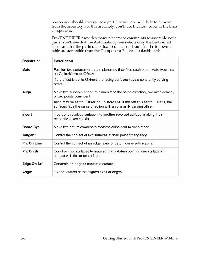
Pro/ENGINEER provides many placement constraints to assemble your parts. You’ll see that the Automatic option selects only the best suited constraint for the particular situation. The constraints in the following table are accessible from the Component Placement dashboard:
Constraint Description
Mate Position two surfaces or datum planes so they face each other. Mate type may be Coincident or Offset.
If the offset is set to Orient, the facing surfaces have a constantly varying offset.
Align Make two surfaces or datum planes face the same direction, two axes coaxial, or two points coincident.
Align may be set to Offset or Coincident. If the offset is set to Orient, the surfaces face the same direction with a constantly varying offset.
Insert Insert one revolved surface into another revolved surface, making their respective axes coaxial.
Coord Sys Make two datum coordinate systems coincident to each other.
Tangent Control the contact of two surfaces at their point of tangency.
Pnt On Line Control the contact of an edge, axis, or datum curve with a point.
Pnt On Srf Constrain two surfaces to mate so that a datum point on one surface is in contact with the other surface.
Edge On Srf Constrain an edge to contact a surface.
Angle Fix the rotation of the aligned axes or edges.
5-2 Getting Started with Pro/ENGINEER Wildfire

Place the Base ComponentThe first step in creating an assembly is importing a base component and automatically aligning its part coordinate system with the assembly’s coordinate system.
1. Click File > New. The New dialog box opens.
2. Select Assembly under Type and enter a name for the assembly. Use the default template.
3. Click OK. The Pro/ENGINEER main window opens and displays the default assembly datum planes, all marked with the prefix ASM_.
4. Click Insert > Component > Assemble on the main menu. The Open dialog box opens.
5. Select front_cover.prt. The front cover of the cell phone model appears and the Component Placement dashboard appears.
6. Click the Default constraint set from the Automatic constraint set list to assemble the front cover in the default constraint position. This constraint aligns the part coordinate system with the assembly coordinate system. You will see the part’s Front, Right, and Top part datum planes align with their respective assembly datum planes. The STATUS line indicates that the base component is fully constrained.
7. Accept and save the assembly.
Assembling the Cell Phone 5-3
Assemble Components to the Base ComponentWith the base component in place, you can start adding the other parts to the assembly. When you select a reference from the assembly and a reference from the part being assembled, Pro/ENGINEER automatically selects a constraint type appropriate to the specified pair of references. How the parts are oriented relative to each other is also considered.
Lens PartIn this procedure you’ll learn how to add the lens part to the assembly using automatically assigned placement constraints.
1. Click Insert > Component > Assemble. Select lens.prt in the directory and click Open. The lens appears next to the base component.
2. Click the Separate Window icon next to the STATUS line in the dashboard. The part is magnified and appears in its own window to improve surface selection. All zoom and pan controls work within the separate window.
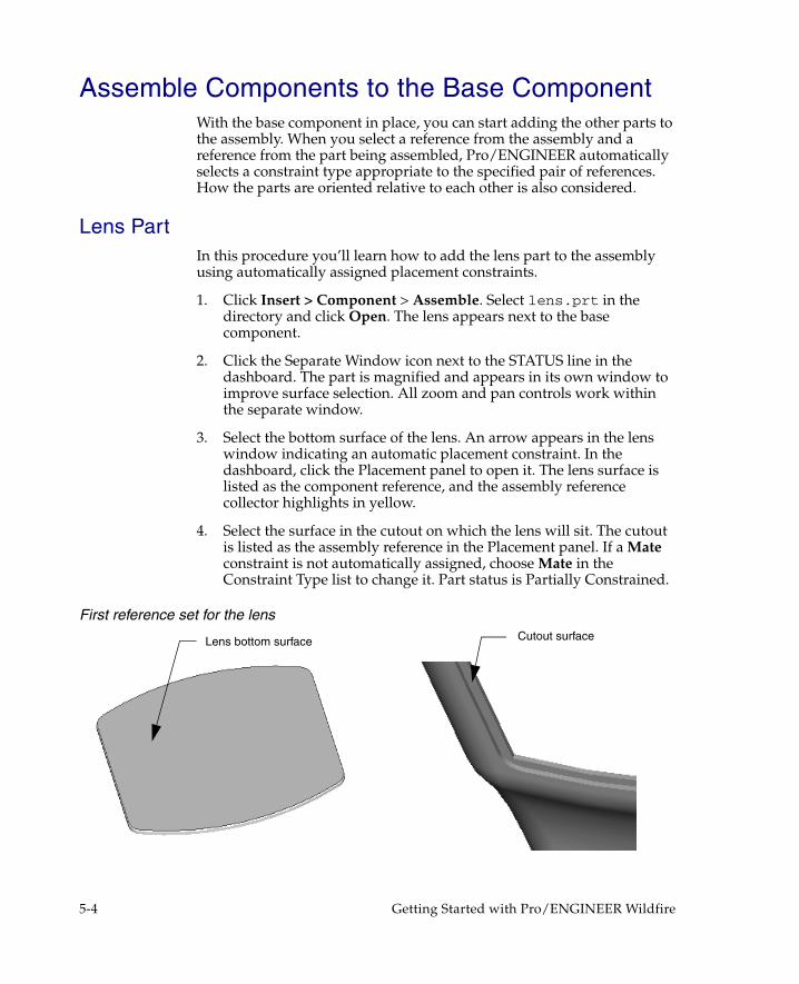
3. Select the bottom surface of the lens. An arrow appears in the lens window indicating an automatic placement constraint. In the dashboard, click the Placement panel to open it. The lens surface is listed as the component reference, and the assembly reference collector highlights in yellow.
4. Select the surface in the cutout on which the lens will sit. The cutout is listed as the assembly reference in the Placement panel. If a Mate constraint is not automatically assigned, choose Mate in the Constraint Type list to change it. Part status is Partially Constrained.
First reference set for the lens
Lens bottom surface Cutout surface
5-4 Getting Started with Pro/ENGINEER Wildfire

5. Click New Constraint in the Placement panel for the next reference set, and then choose Insert from the Constraint Type list. Zoom in to select the bottom edge surface of the lens as the component reference and the bottom surface of the front cover cutout as the assembly reference. The lens is inserted in the cutout area and placement status is Fully Constrained. Click OK and save the assembly.
Second reference set for the lens
Lens fully constrained to the front cover
Lens edge surface
Bottom cutout surface
Assembling the Cell Phone 5-5
Earpiece PartIn this procedure, you will assemble the earpiece to the front cover. The Automatic placement option selects Insert and Mate constraints that were introduced during the lens assembly procedure. This time, you must rotate the cell phone from the default view to select areas inside of the cell phone cover. Use View > View Manager to save a view of the cell phone positioned with the earpiece housing exposed. You can easily return to the same saved view to assemble the microphone to the front cover.
Complete the following steps to assemble the earpiece to the base component:
1. Click Insert > Component > Assemble. Select earpiece.prt in the directory and then click Open. The earpiece appears next to the base component and the Component Placement dashboard appears.
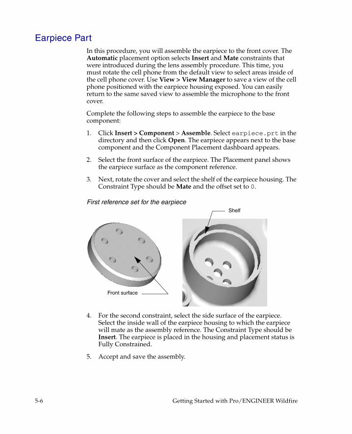
2. Select the front surface of the earpiece. The Placement panel shows the earpiece surface as the component reference.
3. Next, rotate the cover and select the shelf of the earpiece housing. The Constraint Type should be Mate and the offset set to 0.
First reference set for the earpiece
4. For the second constraint, select the side surface of the earpiece. Select the inside wall of the earpiece housing to which the earpiece will mate as the assembly reference. The Constraint Type should be Insert. The earpiece is placed in the housing and placement status is Fully Constrained.
5. Accept and save the assembly.
Shelf
Front surface
5-6 Getting Started with Pro/ENGINEER Wildfire
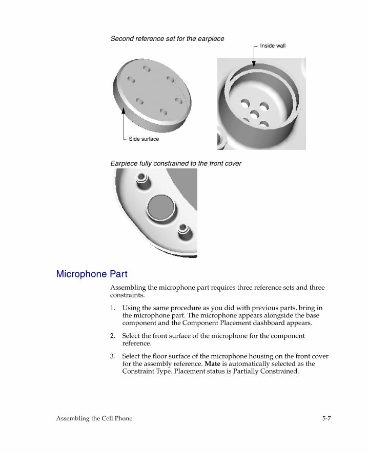
Second reference set for the earpiece
Earpiece fully constrained to the front cover
Microphone PartAssembling the microphone part requires three reference sets and three constraints.
1. Using the same procedure as you did with previous parts, bring in the microphone part. The microphone appears alongside the base component and the Component Placement dashboard appears.
2. Select the front surface of the microphone for the component reference.
3. Select the floor surface of the microphone housing on the front cover for the assembly reference. Mate is automatically selected as the Constraint Type. Placement status is Partially Constrained.
Side surface
Inside wall
Assembling the Cell Phone 5-7

First reference set for the microphone
4. For the next constraint, select one of the long sides of the microphone as the component reference, then select the corresponding microphone housing wall on the front cover for the assembly reference. Constraint Type should be Mate. Placement status is still Partially Constrained. An additional placement constraint is required.
Second reference set for the microphone
5. Select one of the short sides of the microphone as the component reference, then select the corresponding microphone housing wall for the assembly reference. Constraint Type should be Mate. Make sure Coincident is selected as the Offset type. The microphone assembles into its housing, and placement status is Fully Constrained.
6. Accept and save the assembly.
Front surface Floor surface
Corresponding housing wallLong side
5-8 Getting Started with Pro/ENGINEER Wildfire

Third reference set for the microphone
Microphone fully constrained to the front cover
Corresponding housing wall
Offset direction arrowShort side
Assembling the Cell Phone 5-9

PC Board PartYou will use Align and Insert constraints to assemble the PC board to the base component. The front surface of the PC board aligns with the post shelf and with the Right datum planes. The posts on the front cover are then inserted into the PC board’s holes to fully constrain the part.
1. Click Insert > Component > Assemble to import pc_board.prt, as you did with the previous parts.
2. Select the front of the PC board surface (with the datum curve) for the first component reference.
3. Select the shelf located around one of the screw posts on the front cover for the assembly reference. Make sure the Constraint Type is Align.
First reference set for the PC board
4. Now select the Right datum planes on both the PC board and the front cover for the references for the next constraint. The Constraint Type should be Align.
5. For the last constraint, select the outside cylindrical area of one screw post, and then the inside of the corresponding hole on the PC board. The Constraint Type should be Insert. Placement status is Fully Constrained.
6. Accept and save the assembly.
Datum curve
Shelf
Front surface
5-10 Getting Started with Pro/ENGINEER Wildfire

Third reference set for the PC board
PC board fully constrained to the front cover
Outside cylindrical areaInside of the corresponding hole
Assembling the Cell Phone 5-11

Keypad PartThe keypad is the only part that is not assembled directly to the base component. In this procedure, you’ll learn how to hide the front cover so selections on the PC board are easier to make. Next, you’ll assemble the keypad to the board.
When you add a component to an assembly, you may not know where that part fits best, or you might not want to locate it relative to other geometry. You can leave such a component either partially constrained or unconstrained. An unconstrained component is called a packaged component.
In this procedure, you’ll assemble the component, and then close the Component Placement dashboard before the component is fully constrained. The keypad will remain packaged while you create a new assembly datum on the fly to use as a constraint reference. You’ll then use the Edit Definition command to fully constrain the part.
Finally, you’ll use the Unhide command to replace the front cover and create a cutout for the keypad buttons.
Assemble the Keypad1. Select front_cover.prt from the Model Tree. Right-click and
select Hide from the shortcut menu. The cover is now hidden.
2. Bring in keypad.prt to assemble to the PC board.
3. Select the PC board surface between the datum curve boundaries for the assembly reference. Now select the back surface of the keypad for the component reference. The Constraint Type is Mate and Placement Status is Partially Constrained.
First reference set for the keypad
Datum curve boundaries
Back surface
5-12 Getting Started with Pro/ENGINEER Wildfire

4. For the next constraint reference set, select the Right datum planes on the PC board and the keypad. Make sure the Constraint Type is Align and Offset is Coincident. Placement status is Partially Constrained.
5. Click the Check icon to package the assembly and close the Component Placement dashboard. In the Model Tree, a hollow rectangle indicates that the keypad part is a packaged component.
Create a Datum Plane for the PC Board PartA reference surface is required when setting up the final constraint.
1. Right-click pc_board.prt in the Model Tree and then choose Activate from the shortcut menu.
2. Select Insert > Model Datum > Plane. Select the top of the datum curve (closest to the lens cutout on the PC board) for the first reference. The first datum plane reference name and Through constraint appears in the Datum Plane dialog box.
Partially constrained keypad
3. For the second datum plane reference, hold down Ctrl and select the top surface of the PC board. The second datum plane reference name and default constraint appears in the dialog box.
4. Because you want the datum plane perpendicular to the PC board surface, select the second datum plane reference name in the Datum Plane dialog box and choose Normal from the list, and then click OK.
Top of datum curve
Assembling the Cell Phone 5-13

Add the Final Assembly Constraint1. In the Model Tree, right-click the assembly and choose Activate from
the shortcut menu. Right-click keypad.prt and choose Edit Definition from the shortcut menu. The Component Placement dashboard appears. Click New Constraint in the Placement panel to add the final constraint.
2. Select the newly-created datum plane on the PC board, and then the top edge of the keypad. Click OK. Make sure the Constraint Type is Align and Placement Status is Fully Constrained, then click the Check icon and save the assembly.
Third reference set for the keypad
Keypad fully constrained to the PC board
Top surfaceNew datum plane
5-14 Getting Started with Pro/ENGINEER Wildfire

Front Cover PartNow that the keypad is fully constrained to the PC board, you can unhide the front cover. An interference occurs after you unhide the front cover, because the height of the keyboard’s buttons exceeds the cell phone cover thickness. Although the buttons appear to protrude through the front cover, you must cut out the keypad button holes. Using the assembly to cut the holes lets you modify the front cover using the dimensions of the keypad, without opening either part. The holes will be passed back to the cover part as an assembly feature.
Right-click front_cover.prt from the Model Tree and choose Unhide from the shortcut menu.
1. Click Edit > Component Operations > Cut Out.
2. Select the front cover as the part from which to cut out and then click OK.
3. Select the keypad as the design reference for the cutout and then click OK.
4. In the Options menu, click Reference and then Done/Return. The cutout of holes for the keypad buttons is completed.
Move the Keypad to Confirm the CutoutsUse Edit Definition to move the keypad away from the assembly and confirm that the cutouts have been made.
1. Right-click keypad.prt in the Model Tree and click Edit Definition from the shortcut menu.
2. In the Placement panel, select the last Align constraint and clear the Constraint Enabled check box.
3. Open the Move panel. Make sure Translate is selected in the Motion Type list and Relative in View Plane is selected. Click on the keypad to slide it away from the assembly.
4. To replace the keypad, recheck the Constraint Enabled check box and click OK.
Assembling the Cell Phone 5-15
Back Cover PartIn this procedure, you’ll assemble the back cover to the front cover. Because you must select multiple datum planes in this process, click the Settings button on the Model Tree to show the datums so they can be easily located and selected.
1. Click the Settings button above the Model Tree, and then select Tree Filters. The Model Tree Items dialog box opens.
2. Select the Features check box on the Display list, then click OK. All the part features are listed along with the part in the Model Tree.
3. Use Insert > Component > Assemble to bring in back_cover.prt to the cell phone assembly. The Component Placement dashboard appears.
4. Select the Right assembly and back cover datums from the Model Tree as the first Align Coincident constraint set.
5. Continue to add constraint sets to match the assembly Front and Top datums to their respective part datums until Placement Status is Fully Constrained.
6. Click the Check icon. Save the assembly.
5-16 Getting Started with Pro/ENGINEER Wildfire

Antenna PartThe last part to be assembled is the antenna. It is inserted into the hole on the back cover.
1. Bring in antenna.prt to the cell phone assembly.
2. Select the bottom surface of the antenna tip as the component reference and the top surface of the antenna brace as the assembly reference. Make sure the Constraint Type is Mate Coincident.
First reference set for the antenna
3. For the next constraint, select the datum axis for both the antenna and hole into which the antenna will be inserted. An Align constraint is chosen automatically. Placement Status is Fully Constrained.
4. The cell phone is now completely assembled. Click the Check icon and save the assembly.
Second reference set for the antenna
Top surface
Bottom surface
Hole datum axis
Antenna datum axis
Assembling the Cell Phone 5-17

Create an Exploded View of the AssemblyAn exploded view displays part relationships in an assembly. Exploded views do not affect assembly constraints or final part positioning. When a model is exploded, the parts are separated on a random basis and may need to be rearranged. Use View > Explode > Edit Position to change the exploded view.
1. Open the completely assembled cell phone model file.
2. Click View > Explode > Explode View. The assembly explodes to default positions.
Modifying the Exploded Component PositionsTo move the exploded components to new default positions, complete the following steps:
1. Click View > View Manager. The View Manager dialog box opens.
2. Click the Explode tab, the Properties button, and then the Edit Position icon. The Explode Position dialog box opens.
3. Select Plane Normal from the Motion Reference list.
The Explode Position dialog box
5-18 Getting Started with Pro/ENGINEER Wildfire

NoteA surface or a datum plane is used to specify a motion reference when placing components. In the Explode Position dialog box, the Motion References options restrict component movement in various ways, while the View Plane option allows components to move freely within the display area.
4. Select a plane on your cell phone model to use as the motion reference, and then select a component to move on the exploded assembly model.
5. Use the mouse to move and place the component. Middle-click to cancel the movement operation. Repeat to move other components.
6. To save the new explode state, click the List button, and then the Edit tab. Choose Save from the list and close the View Manager.
7. In the View Manager, click the Explode/Unexplode icon to return to the assembled view. Close the View Manager.
Exploded and unexploded views of the assembly
Assembling the Cell Phone 5-19

Modify the AssemblyNow that the model is assembled, you may want to modify some or all of its features. You can make changes from within Assembly mode instead of entering Part mode for each of the components.
This section describes ways to make changes to your design from the assembly level. You can create, delete, suppress, and modify part features from Assembly mode. When you modify a component in Assembly mode, the changes automatically update in Part and Drawing modes.
Redefine Assembly Placement ConstraintsNow you can modify placement constraints for the antenna so it extends further from the cell phone body.
1. Right-click antenna.prt from the Model Tree and choose Edit Definition from the shortcut menu.
2. Enter 50.00 for the Mate offset value. The antenna is extended. Accept the change.
Suppress and Resume PartsSuppressed parts in an assembly behave just like suppressed features in a part. Parts that are surpressed are temporarily removed from an assembly, but they can be returned to the model with the Resume command.
Features may be suppressed to save time and memory when working with large assemblies, improve regeneration and display time, or to try out different design iterations.
NoteClick the Settings button above the Model Tree, and then click Tree Filters. The Model Tree Items dialog box opens. Select the Suppressed Objects check box on the Display list, and then click OK. All suppressed items are now displayed in the Model Tree. Once the parts are displayed, they can be selected and resumed.
5-20 Getting Started with Pro/ENGINEER Wildfire

Modify Part Dimension ValuesYou can modify assembly or part dimension values from within the assembly. In this procedure you modify the dimension of the antenna tip.
1. Right-click antenna.prt on the Model Tree, choose Activate from the shortcut menu, and then double-click the antenna tip. The dimension values are displayed on the model.
2. Double-click the dimension value to be modified (12.50). Enter a new value of 25.00 and then press Enter.
3. Click or Edit > Regenerate. The antenna tip reflects the changed dimension.
Antenna tip: before and after modification
SummaryWith the assembly complete, you can make the drawings for manufacturing. Pro/ENGINEER creates dimensioned drawings using the dimensions that have already been entered in the first two phases of designing the cell phone. The dimensions are viewed selectively as needed.
12.50
25.00
Assembling the Cell Phone 5-21