Embed Size (px)
DESCRIPTION
Citation preview

CHAPTER 7.0 DESIGN OF POROUS PAVEMENTS FOR COMMERCIAL FACILITIES
7.1 INTRODUCTION
Porous asphalt pavements are increasingly in
demand because they offer site planners and public works officials the opportunity to minimize impervious surfaces and manage stormwater in an environmentally friendly way.
Impervious surfaces such as roofs and pavements create runoff, so that dirt and debris are washed into streams and waterways. At the same time, water has often been regarded as the “enemy” of asphalt. Great efforts are taken to assure that water does not enter the roadway material, especially in areas with numerous freeze/thaw cycles.
Ironically enough, porous asphalt offers the opportunity to address both of these problems in many parking lot and paved area applications. With the proper design and installation, porous asphalt parking areas can provide cost-effective, attractive parking lots with a life span of twenty years or more, and at the same time, provide stormwater management systems that promote infiltration, improve water quality, and eliminate the need for a detention basin. While this almost sounds too good to be true, the technology is really quite simple.
The secret to success is to provide the water with a place to go, usually in the form of an underlying, open-graded stone bed. As the water drains through the porous asphalt and into the stone bed, it slowly infiltrates into the soil. The stone bed size and depth must be designed so that the water level never rises into the asphalt. This stone bed, often eighteen to thirty-six inches in depth, provides a tremendous subbase for the asphalt paving. Even after twenty years, porous lots show little if any cracking or pothole problems. The surface wears well, and while slightly coarser than standard asphalt, it is attractive and acceptable – most people parking on the lot will not notice (or believe) that it is porous.
Porous asphalt does not necessarily require additives or proprietary ingredients, although polymers and/or fibers can be used to prevent draindown and to improve durability and shear strength. Constructing a permeable surface does not require the contractor to have special paving equipment or skills. With the proper information, most asphalt plants can easily prepare the mix and general paving contractors can install it. A porous pavement is defined as one that allows water to drain all the way through the pavement structure.
This article will discuss the background and costs
of porous pavement, cite examples of successful installations, explain how it works, and explore design considerations. It will also discuss issues including soil and subsurface conditions, infiltration, water quality, construction, and maintenance.
7.2 BACKGROUND
First developed in the 1970s at the Franklin
Institute in Philadelphia, porous asphalt pavement consists of standard bituminous asphalt in which the aggregate fines (particles smaller than 600 um, or the No. 30 sieve) have been screened and reduced, allowing water to pass through the asphalt (Figure 1).
Figure 7.1 Water Pass Underneath the pavement is placed a bed of
uniformly graded, clean- washed aggregate with a void space of 40 percent. Stormwater drains through the asphalt, is held in the stone bed, and infiltrates slowly into the underlying soil mantle. A layer of geotextile filter fabric separates the stone bed from the underlying soil, preventing the movement of fines into the bed (Figure 2).
Porous pavement is especially well suited for parking lot areas. Several dozen large, successful porous pavement installations, including some that are now 20 years old, have been developed by Cahill Associates (CA) of West Chester, Pennsylvania, mainly in Mid-Atlantic states. These systems continue to work quite well as both parking lots and stormwater management systems. In fact, many of these systems have outperformed their conventionally paved counterparts in terms of both parking lot durability and stormwater management.
7-1

Figure 7.2 – Cross-Section Cost
Porous pavement does not usually cost more than conventional pavement. On a yard-by-yard basis, the asphalt cost is approximately the same as the cost of conventional asphalt. The underlying stone bed is usually more expensive than a conventional compacted sub-base, but this cost difference is generally offset by the significant reduction in stormwater pipes and inlets. Additionally, because porous pavement is designed to “fit into” the topography of a site, there is generally less earthwork and are no deep excavations.
When the cost savings provided by eliminating the detention basin are considered, porous pavement is generally an economically sound choice. On those jobs where unit costs have been compared, the porous pavement has always been the less expensive option. Current jobs are averaging between $2,000 and $2,500 per parking space for parking, aisles, and stormwater management.
A recent installation at the University of North Carolina in Chapel Hill included parking lots where some sections were constructed from porous asphalt and some sections used porous concrete. The cost differential was approximately 4:1 – that is, the porous concrete pavement cost four times as much as the porous asphalt pavement. All other installations cited in this article are asphalt pavements.
7. 3 INSTALLATIONS OLD AND NEW One of the first large-scale porous
pavement/recharge bed systems that CA designed is located in a corporate office park in the suburbs of Philadelphia (East Whiteland Township, Chester County). This particular installation of about 600 parking spaces posed a challenge because of both the sloping topography and the underlying carbonate geology that was prone to sinkhole formation. The site also is immediately adjacent to Valley Creek, designated by Pennsylvania as an Exceptional Value
stream where avoiding nonpoint source pollution is of critical importance.
Constructed in 1983 as part of the Shared Medical Systems (now Seimens) world headquarters, the system consists of a series of porous pavement/recharge bed parking bays terraced down the hillside connected by conventionally paved impervious roadways. Both the top and bottom of the beds are level, as seen in Figure 3, hillside notwithstanding. After twenty years, the system continues to function well and has not been repaved. Although this area is naturally prone to sinkholes, far fewer sinkholes have occurred in the porous asphalt areas than in the conventional asphalt areas, which the site manager attributes to the broad and even distribution of stormwater over the large areas under the porous pavement parking bays.
Figure 7.3 – Benched Parking Bays
Other early 1980s sites, such as the SmithKline Beecham (now Quest) Laboratory in Montgomery County, Pennsylvania, and the Chester County Work Release Center in Chester County, Pennsylvania, also used the system of “terracing” the porous paved recharge beds down the hillside to overcome the issues of slope. At the DuPont Barley Mills office complex in Delaware, the porous pavement was constructed specifically to avoid the construction of a detention basin, which would have destroyed the last wooded portion of the site. More recently (1997), the porous parking lots at the Pennsylvania State Berks Campus were constructed to avoid destroying a wooded campus hillside. The Pennsylvania State Berks lots, also on carbonate bedrock, replaced an existing detention basin and have not experienced the sinkhole problems that another campus detention basin has suffered.
7.4 HOW IT WORKS The porous asphalt mix has a lower concentration
of fines than traditional asphalt, as shown in Table 1, accomplished by straightforward screening. In all other manufacturing aspects, porous asphalt is the same as conventional asphalt and can be mixed at a standard asphalt batch plant. With fewer fines, the asphalt is
7-2

porous and allows water to drain though the material through virtually imperceptible openings (To the untrained eye, porous pavement properly prepared is difficult to distinguish from conventional pavement.). There are several variations of the mix, including gradations developed by various state transportation departments seeking a pavement that also can be used to reduce noise and skidding. For the purposes of stormwater management, we have found the best performance from the mix indicated in Table 1.
US Standard Sieve Size Percent Passing
1/2" 100 3/8" 95 #4 35 #8 15 #16 10 #30 2
Percent bituminous 5.75% to 6.0% by weight
Table 7. 1 – Standard Porous Asphalt Mixes
The underlying stone recharge bed consists of a
uniformly graded (i.e., screened) 1.5- inch to 2.5-inch clean-washed stone mix, such as an AASHTO No. 3. Depending on local aggregate availability, both larger and smaller size stones have been used. The important requirement is that the stone be uniformly graded (to maximize void space) and clean washed. The void space between the stones provides the critical storage volume for the stormwater. Stones that are dusty or dirty may clog the infiltration bed and must be avoided.
The stone bed is usually between eighteen and thirty-six inches deep, depending on stormwater storage requirements, frost depth considerations, and site grading. This depth provides a significant structural base for the pavement. As a result, porous asphalt exhibits very few of the cracking and pothole formation problems encountered in conventional pavement.
The bottom of the recharge bed is excavated to a level surface and is not compacted. This allows water to distribute and infiltrate evenly over the entire bed bottom area. Compaction of the soils will prevent infiltration, so it is important that care be taken during excavation to prevent this. The bottom of the bed cannot be placed on fill material unless that fill material is stone. A layer of non-woven geotextile at the bottom of the bed allows the water to drain into the soil while preventing the soil particles from moving into the stone bed. The steps involved in a typical porous asphalt installation are shown on page 7-9.
Very often, the underlying stone bed can also provide stormwater management for adjacent impervious areas such as roofs and roads. To achieve this, we convey the stormwater directly into the stone bed and then use perforated pipes in the stone bed to distribute the water evenly (Figure 4).
Figure 7.4 – Roof Leaders
Roof leaders can be connected directly to the subsurface infiltration bed. • Precipitation is carried from roof by roof drains to
storage beds. • Stormwater runoff from impervious areas and lawn
areas is carried to storage beds. • Precipitation that falls on pervious paving enters
storage bed directly. • Stone beds with 40 percent void space store storm-
water. Perforated pipes distribute stormwater from impervious surfaces evenly throughout the beds.
• Stormwater exfiltrates from storage beds into soil and recharges the groundwater.
Figure 7.5 – Perforated Pipes
7.5 DESIGN CONSIDERATIONS In the late 1970s and early 1980s, as we designed our first systems, we were uncertain how well the porous asphalt would hold up over time and use. In these first systems, we designed the parking spaces with porous pavement but constructed the aisles and connector roadways with conventional asphalt. We extended the
7-3
stone stormwater storage/infiltration bed under the entire parking area, however, including the areas with impervious paving.
Over time, we have found that the porous asphalt material has held up as well as, or better than, the conventional asphalt, largely due to the solid sub-base provided by the stone storage/infiltration bed. In subsequent designs we have paved the entire surface in the porous asphalt. We have found that sufficient asphalt content is essential to pavement durability (5.75 percent to 6.0 percent bituminous asphalt by weight). In sites where a lower asphalt content was used, some surface scuffing and/or raveling can be observed on the pavement surface. In different situations, we have tried various commercial additives intended to improve strength or performance in cold weather, but in general have avoided any proprietary mixes or additives.
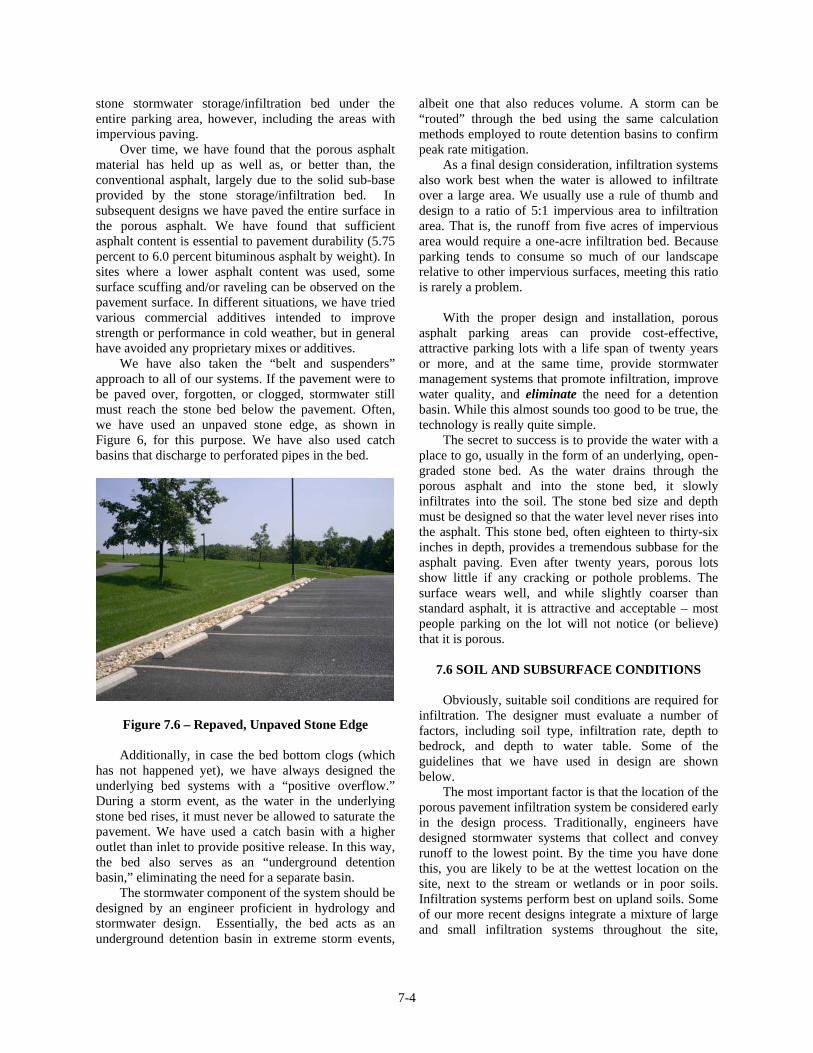
We have also taken the “belt and suspenders” approach to all of our systems. If the pavement were to be paved over, forgotten, or clogged, stormwater still must reach the stone bed below the pavement. Often, we have used an unpaved stone edge, as shown in Figure 6, for this purpose. We have also used catch basins that discharge to perforated pipes in the bed.
Figure 7.6 – Repaved, Unpaved Stone Edge
Additionally, in case the bed bottom clogs (which has not happened yet), we have always designed the underlying bed systems with a “positive overflow.” During a storm event, as the water in the underlying stone bed rises, it must never be allowed to saturate the pavement. We have used a catch basin with a higher outlet than inlet to provide positive release. In this way, the bed also serves as an “underground detention basin,” eliminating the need for a separate basin.
The stormwater component of the system should be designed by an engineer proficient in hydrology and stormwater design. Essentially, the bed acts as an underground detention basin in extreme storm events,
albeit one that also reduces volume. A storm can be “routed” through the bed using the same calculation methods employed to route detention basins to confirm peak rate mitigation.
As a final design consideration, infiltration systems also work best when the water is allowed to infiltrate over a large area. We usually use a rule of thumb and design to a ratio of 5:1 impervious area to infiltration area. That is, the runoff from five acres of impervious area would require a one-acre infiltration bed. Because parking tends to consume so much of our landscape relative to other impervious surfaces, meeting this ratio is rarely a problem.
With the proper design and installation, porous asphalt parking areas can provide cost-effective, attractive parking lots with a life span of twenty years or more, and at the same time, provide stormwater management systems that promote infiltration, improve water quality, and eliminate the need for a detention basin. While this almost sounds too good to be true, the technology is really quite simple.
The secret to success is to provide the water with a place to go, usually in the form of an underlying, open-graded stone bed. As the water drains through the porous asphalt and into the stone bed, it slowly infiltrates into the soil. The stone bed size and depth must be designed so that the water level never rises into the asphalt. This stone bed, often eighteen to thirty-six inches in depth, provides a tremendous subbase for the asphalt paving. Even after twenty years, porous lots show little if any cracking or pothole problems. The surface wears well, and while slightly coarser than standard asphalt, it is attractive and acceptable – most people parking on the lot will not notice (or believe) that it is porous.
7.6 SOIL AND SUBSURFACE CONDITIONS
Obviously, suitable soil conditions are required for infiltration. The designer must evaluate a number of factors, including soil type, infiltration rate, depth to bedrock, and depth to water table. Some of the guidelines that we have used in design are shown below.
The most important factor is that the location of the porous pavement infiltration system be considered early in the design process. Traditionally, engineers have designed stormwater systems that collect and convey runoff to the lowest point. By the time you have done this, you are likely to be at the wettest location on the site, next to the stream or wetlands or in poor soils. Infiltration systems perform best on upland soils. Some of our more recent designs integrate a mixture of large and small infiltration systems throughout the site,
7-4

including porous pavement, to avoid conveying stormwater any distance.
Here is a summary of design guidelines for subsurface infiltration.
Avoid piping water long distances. Look for infiltration opportunities within the immediate project area.
Consider past uses of the site and appropriateness of infiltration design and porous pavement.
Consider the source of runoff. Incorporate sediment reduction techniques as appropriate.
Perform site tests to determine depth to seasonal high water table, depth to bedrock, and soil conditions, including infiltration capabilities. Design accordingly. Maintain three feet above high water table and two feet above bedrock.
Avoid excessive earthwork (cut and fill). Design with the contours of the site. Maintain a sufficient soil buffer above bedrock.
Do not infiltrate on compacted fill. Avoid compacting soils during construction. Maintain erosion and sediment control
measures until site is stabilized. Sedimentation during construction can cause the failure of infiltration systems.
Spread the infiltration over the largest area feasible. Avoid concentrating too much runoff in one area. A good rule of thumb is 5:1 impervious area to infiltration area (i.e., 5 acres of impervious area to 1 acre of infiltration area). A smaller ratio is appropriate in carbonate bedrock areas.
The bottom of the infiltration area should be level to allow even distribution.
The slope on which the porous pavement is placed should not exceed 5 percent. Use conventional pavement in steep areas that receive vehicular traffic.
Provide thorough construction oversight.
Before any infiltration system is designed, soil investigation must be done. This consists of two steps. First, a simple “deep hole” six to eight feet in depth (Figure 7) is excavated with a backhoe and the soil conditions are observed. While some designers prefer an auger, we believe that there is no substitute for physically observing and describing the soil horizons. Next, infiltration measurements are performed at the approximate bed bottom location. We have used both simple percolation tests, which are not very scientific, as well as infiltrometer readings. We do not consider infiltration rates between 0.1 inch per hour and 0.5 inch
per hour too slow; rather, this means that infiltration will occur slowly over a two- to three-day period, which is ideal for water quality improvement.
Figure 7.7 – Deep Hole Excavation
Underlying geology must also be considered in areas such as those underlain by carbonate formations. In that situation, more detailed site investigation may include borings and ground-penetrating radar. Contrary to popular belief, properly designed infiltration systems do not create sinkholes. A number of our systems, including older systems, are located in carbonate areas. In several situations, we have successfully installed porous pavement infiltration systems adjacent to areas where detention basins had previously created sinkholes.
7.7 WHEN INFILTRATION IS LIMITED
Despite the need for infiltration, not all sites and soils are suitable. In those situations, we have designed porous pavement systems to reduce impervious surfaces or as part of a water quality improvement program. The porous pavement parking lots recently constructed at the John Heinz National Wildlife Refuge near the Philadelphia Airport are located in a wet, low-lying site that has been subject to fill over the years. The soils are not well drained. In this situation, a trench was excavated to a lower gravel layer to facilitate infiltration, but the parking lots primarily serve to avoid the creation of new impervious surfaces at this valuable wildlife refuge.
At the Ford Motor Company Rouge River Facility in Dearborn, Michigan, the use of porous pavement is an important part of Ford’s commitment to sustainability. The original manufacturing plant was constructed in a low-lying, wet area and has been subject to a century of industrial use. In 1999, Ford constructed a porous parking lot designed to slowly drain to a series of planted wetland swales (Figures 8 and 9).
7-5

The stormwater stored in the beds beneath the porous pavement supports the vegetated swales by discharging slowly to the planted areas. The system is specifically designed to improve water quality. Referred to as the “Mustang Lot” (because new Ford Mustangs are parked there after assembly), the lot has worked well, and current Ford plans include the construction of additional areas of porous pavement areas that will drain to constructed stormwater wetlands.
David Swisher, have conducted research at the Pennsylvania State University. Dr. Dempsey has been studying a porous pavement system constructed at the Centre County/Pennsylvania State Visitor Center in 1999, comparing the water quality in the infiltration beds to observed runoff from a nearby impervious parking lot. Dr. Dempsey has monitored the infiltration rates of this system and found that the system has maintained a consistent infiltration rate. During a 25-year precipitation event, there was no surface discharge from the stone beds.
Figure 7.8 – Mustang Lot
7.8 WATER QUALITY
There has been limited sampling data on the porous
pavement systems, although the available data indicate a very high removal rate for total suspended solids, metals, and oil and grease (Table 3). More recently, Brian Dempsey, Ph.D., and his research assistant,
Figure 7.9 – Porous & Standard Lot Sections
INFILTRATION BMP TYPE Water Quality Parameter Trench Trench Porous
Paving Porous Paving
Average Removal Efficiency
TSS 90% --- 95% 89% 91% TP 60% 68% 71% 65% 66% TN 60% --- --- 83% 72%
TOC 90% --- --- 82% 86% Pb --- --- 50% 98% 74% Zn --- --- 62% 99% 81%
Metals 90% --- --- --- 90% Bacteria 90% --- --- --- 90%
BOD 75% --- --- --- 75% Cd --- --- 33% --- 33% Cu --- --- 42% --- 42%
TKN --- 53% --- --- 53% Nitrate --- 27% --- --- 27%
Ammonia --- 81% --- --- 81%
Table 2 – Water Quality Benefits of Porous Pavement with Infiltration
7-6

7.9 CONSTRUCTION
Almost always, when an infiltration Best Management Practice (BMP) fails, it is due to difficulties and mistakes in the design and construction process. This is true for porous pavement and all other infiltration BMPs. Carelessness in compacting the subgrade soils, poor erosion control, and poor-quality materials are all causes of failure. For that reason, we provide detailed specifications on site protection, soil protection and system installation.
On every project, we meet with the contractor before construction and discuss the need to prevent heavy equipment from compacting soils, the need to prevent sediment-laden waters from washing on to the pavement, the need for clean stone, etc. We verbally review the installation process with the project foreman. During construction, we routinely stop by the site or provide construction advice. Successful installation of any infiltration BMP is a hands-on process that requires an active role for the designer. While we have prevented failures with this approach, most of the problems we have seen at other infiltration BMPs are a result of construction problems. Often, the failure does not lie with the contractor or with poor soils, but instead is due to a lack of specific guidance for construction procedures.
Because construction sites are inherently messy places, we have often found it best to install the porous pavement towards the end of the construction period. By doing this, there is less risk of creating problems. On many projects, we will excavate the stone bed area to within six inches of the final grade and use the empty bed area as a temporary sediment basin and stormwater structure. Care must be taken to prevent heavy equipment from compacting the soils, but sediment can accumulate.
In the later stages of the project, the sediment is removed, the bed is excavated to final grade, and the porous pavement system is installed. This also avoids the need for a separate sediment basin during construction.
7.10 MAINTENANCE
We recommend that all porous pavement surfaces be vacuum-swept twice per year with an industrial vacuum sweeper. Unfortunately, like many stormwater maintenance requirements, this advice is often overlooked or forgotten. Fortunately, even without regular maintenance, the systems continue to function (We routinely send observers out in heavy storms to confirm this.).
When runoff is conveyed from adjoining areas or roof surfaces into the bed, we often use a drop inlet box or other structure to reduce the amount of detritus and sediment that is conveyed to the bed. This structure also requires regular removal of sediment and debris.
7.11 DEICING AND FREEZING ISSUES
One of the most common questions relates to concerns about freezing conditions. Freezing has not been an issue, even in very cold climates. We were quite surprised when the owners of early installations first told us that there was less need to snowplow on the porous pavement surfaces. The water drains through the pavement and into the bed below with sufficient void space to prevent any heaving or damage, and the formation of “black ice” is rarely observed. The porous surfaces tend to provide better traction for both pedestrians and vehicles than conventional pavement. Not a single system has suffered freezing problems.
Obviously, the use of sand or gravel for deicing would be detrimental to the porous surface. Salt may be used, however, and the surface may be plowed if needed. Most sites have found that light plowing eliminates the need for salt since the remaining snow quickly drains through the asphalt. This has the added benefit of reducing groundwater and soil contamination from deicing salts.
7.12 WHERE IT DOESN’T WORK
Porous asphalt is not recommended for slopes over 6 percent. We have not used the material for roadways, although it has been applied to some degree in Europe. There are also locations where the threat of spills and groundwater contamination is quite real. In those situations (such as truck stops and heavy industrial areas), we have applied systems to treat for water quality (such as filters and wetlands) before any infiltration occurs. The ability to contain spills must also be considered and built into the system. Finally, we have avoided the use of porous asphalt in areas where the pavement is likely to be coated or paved over due to a lack of awareness, such as individual home driveways.
7.13 VARIATIONS ON THE THEME: POROUS WALKWAYS AND PLAYGROUNDS, POROUS
CONCRETE
More recently, we have applied the asphalt to situations such as walkways and playgrounds, including paths at Swarthmore College in Philadelphia (Figure 10)
7-7

Figure 7.10 – Porous Asphalt Walking Paths
and an urban playground at the Penn New School in Philadelphia (Figure 11). At Swarthmore College, the paths are not part of an infiltration bed but are merely intended to reduce impervious cover. The Penn New School project works to reduce the volume of stormwater discharging to the Philadelphia combined sewer overflows. Both of these applications are “retrofits” in urban areas that were previously paved.
Figure 7.11 – Porous Playground
Although we have used other materials such as porous concrete for both sidewalks and parking areas, the asphalt is less expensive and easier to install, and it remains our first choice. Even in hot Southern climates, such as the University of North Carolina in Chapel Hill (Figure 12) where two large commuter parking lots have recently been installed, the porous asphalt has performed quite well.
Figure 7.12 – Large Commuter Parking Lot
7.14 SUMMARY Porous bituminous asphalt for parking lots has
proven itself to be one of the most effective and affordable techniques for addressing stormwater management from development. It performs in both hot and cold climates and in a variety of situations. To date, our installations include pavements at schools and universities, corporate offices, industrial sites, shopping centers, parks, libraries, a prison, and even fast food restaurants. Porous asphalt is cost-effective, long-lasting, and an ideal solution to reducing the environmental effects of pavement.
7.15 REFERENCES This chapter is a reprint of an article written by Thomas H. Cahill, P.E., Michele Adams, P.E., and Courtney Marm of Cahill Associates
7-8

CONSTRUCTION SEQUENCE FOR POROUS ASPHALT PARKING LOT with SUBSURFACE INFILTRATION BED
2. Earthen berms (if used) between infiltration beds should be left in place during excavation. These berms do not require compaction if proven stable during construction.
1. The subsurface infiltration bed located beneath the porous pavement must be excavated without heavy equipment compacting the bed bottom. Fine grading is done by hand.
4. Clean (washed) uniformly graded aggregate is placed in the bed as the storage media.
3. Non-woven geotextile is laid immediately after fine grading is completed.
5. The asphalt is laid down just like standard asphalt.
6. The finished surface looks like standard asphalt – until it rains. Infiltration beds are completely under the parking lots, minimizing the disturbance envelope.
7-9