Embed Size (px)
Citation preview
© 2013 Aspen Technology, Inc. All rights reserved
Compressor Modeling Using Aspen HYSYS Dynamics
Glenn Dissinger, Director of Product Management
Martyn Blanchard, Global Practice Director
Engineering Collaboration Webinar Series
April 23, 2013
© 2013 Aspen Technology, Inc. All rights reserved |
2
Ongoing Series of Technical Webinars Engineering Webinars for Education and Best Practices
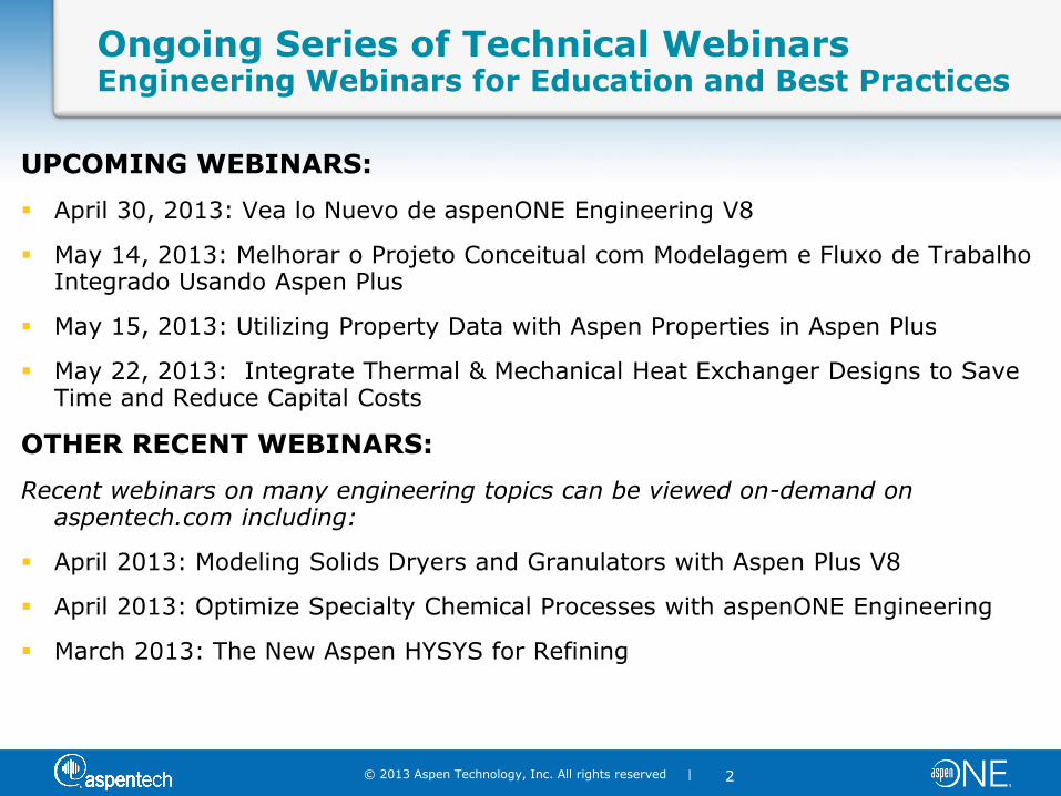
UPCOMING WEBINARS:
April 30, 2013: Vea lo Nuevo de aspenONE Engineering V8
May 14, 2013: Melhorar o Projeto Conceitual com Modelagem e Fluxo de Trabalho Integrado Usando Aspen Plus
May 15, 2013: Utilizing Property Data with Aspen Properties in Aspen Plus
May 22, 2013: Integrate Thermal & Mechanical Heat Exchanger Designs to Save Time and Reduce Capital Costs
OTHER RECENT WEBINARS:
Recent webinars on many engineering topics can be viewed on-demand on aspentech.com including:
April 2013: Modeling Solids Dryers and Granulators with Aspen Plus V8
April 2013: Optimize Specialty Chemical Processes with aspenONE Engineering
March 2013: The New Aspen HYSYS for Refining
© 2013 Aspen Technology, Inc. All rights reserved |
3
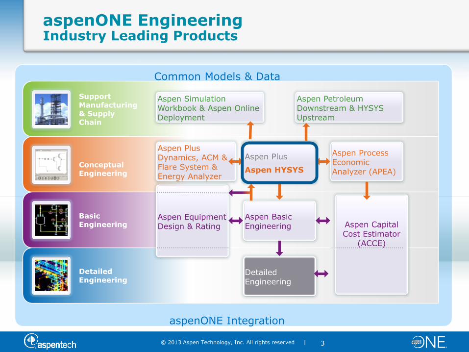
Common Models & Data
aspenONE Integration
Support Manufacturing & Supply Chain
Conceptual Engineering
Basic Engineering
Detailed Engineering
aspenONE Engineering Industry Leading Products
Aspen Simulation Workbook & Aspen Online Deployment
Aspen Petroleum Downstream & HYSYS Upstream
Aspen Equipment Design & Rating
Aspen Basic Engineering Aspen Capital
Cost Estimator (ACCE)
Aspen Plus Dynamics, ACM & Flare System & Energy Analyzer
Aspen Plus
Aspen HYSYS
Aspen Process Economic Analyzer (APEA)
Detailed Engineering
Aspen Plus
Aspen HYSYS
© 2013 Aspen Technology, Inc. All rights reserved |
4
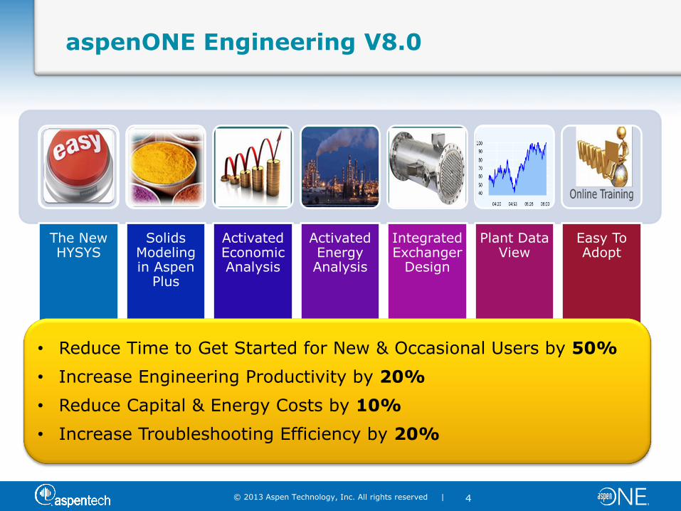
aspenONE Engineering V8.0
The New HYSYS
Solids Modeling in Aspen
Plus
Activated Economic Analysis
Activated Energy Analysis
Integrated Exchanger
Design
Plant Data View
Easy To Adopt
• Reduce Time to Get Started for New & Occasional Users by 50%
• Increase Engineering Productivity by 20%
• Reduce Capital & Energy Costs by 10%
• Increase Troubleshooting Efficiency by 20%
© 2013 Aspen Technology, Inc. All rights reserved |
5
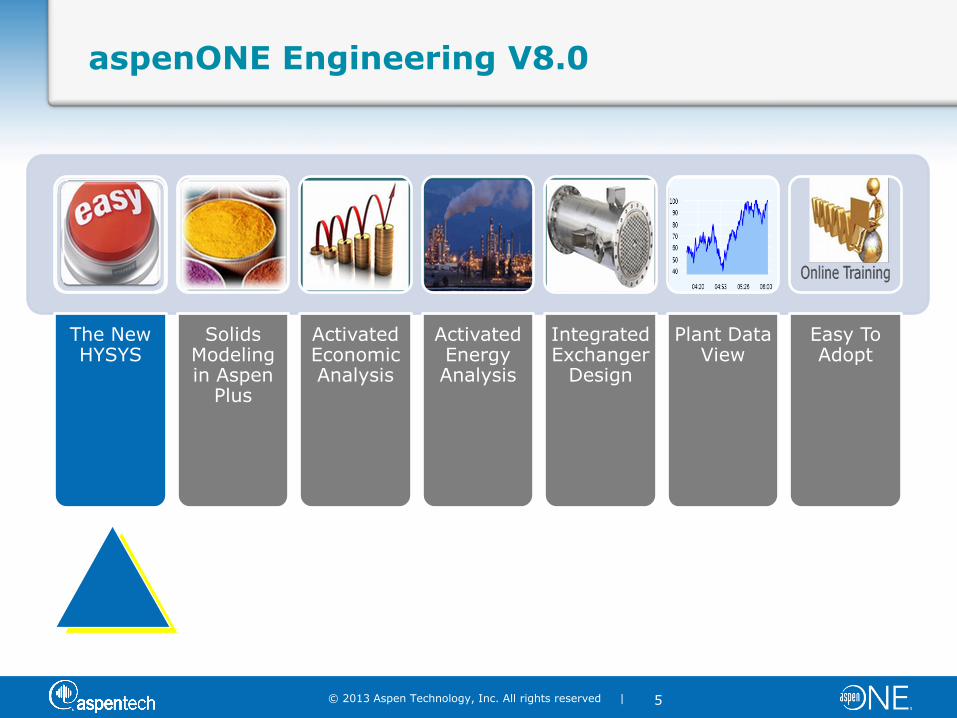
aspenONE Engineering V8.0
The New HYSYS
Solids Modeling in Aspen
Plus
Activated Economic Analysis
Activated Energy Analysis
Integrated Exchanger
Design
Plant Data View
Easy To Adopt
© 2013 Aspen Technology, Inc. All rights reserved |
6
Compressor Modeling Using Aspen HYSYS Dynamics
Glenn Dissinger, Director of Product Management
Martyn Blanchard, Global Practice Director
© 2013 Aspen Technology, Inc. All rights reserved |
7
Disclaimer
Aspen Technology may provide information regarding possible future product developments including new products, product features, product interfaces, integration, design, architecture, etc. that may be represented as “product roadmaps.”
Any such information is for discussion purposes only and does not constitute a commitment by Aspen Technology to do or deliver anything in these product roadmaps or otherwise.
Any such commitment must be explicitly set forth in a written contract between the customer and Aspen Technology, executed by an authorized officer of each company.
© 2013 Aspen Technology, Inc. All rights reserved |
8
Outline
Overview of HYSYS V8
Compressor Overview
– Types
– What’s Important to Consider
– Surge
Modeling Compressors in HYSYS
– Overview
– Demo
Compressor Trip Case Studies
– Best Practices
– Customer Examples
– AspenTech Global Services & Capabilities
Wrap-Up and Q&A
© 2013 Aspen Technology, Inc. All rights reserved |
9
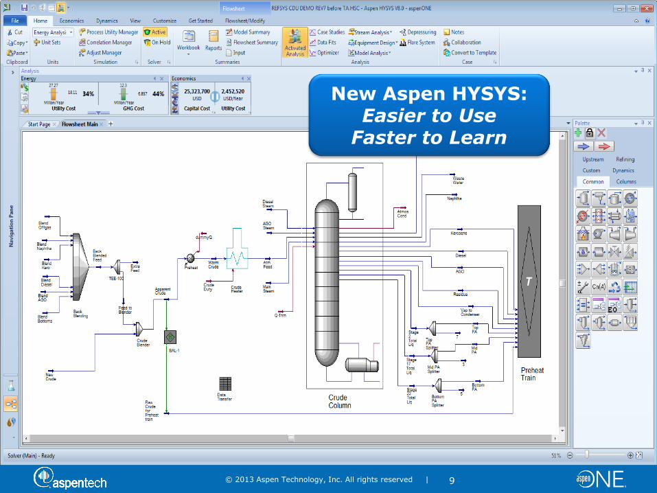
New Aspen HYSYS: Easier to Use
Faster to Learn
© 2013 Aspen Technology, Inc. All rights reserved |
10
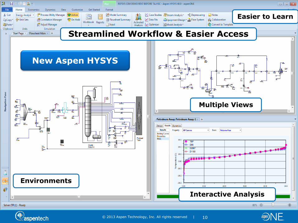
Multiple Views
Interactive Analysis
Environments
Streamlined Workflow & Easier Access
Easier to Learn
New Aspen HYSYS
© 2013 Aspen Technology, Inc. All rights reserved |
11
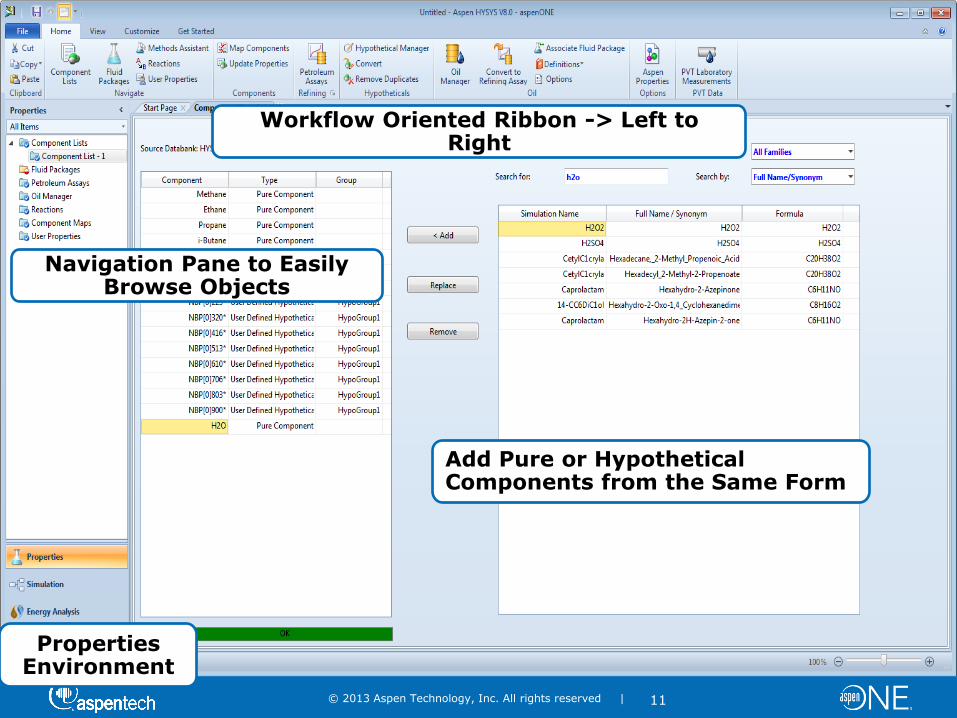
Add Pure or Hypothetical Components from the Same Form
Properties Environment
Workflow Oriented Ribbon -> Left to Right
Navigation Pane to Easily Browse Objects
© 2013 Aspen Technology, Inc. All rights reserved |
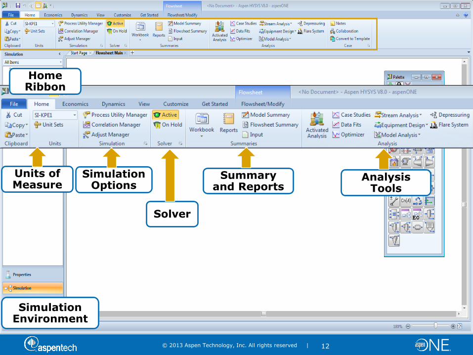
12
Units of Measure
Simulation Options
Home Ribbon
Solver
Summary and Reports
Analysis Tools
Simulation Environment
© 2013 Aspen Technology, Inc. All rights reserved |
13
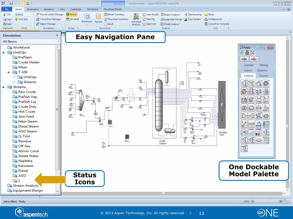
Easy Navigation Pane
Status Icons
One Dockable Model Palette
© 2013 Aspen Technology, Inc. All rights reserved |
14
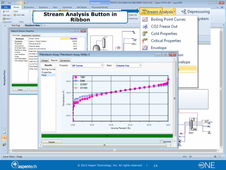
Stream Analysis Button in Ribbon
One Click to Analyze
© 2013 Aspen Technology, Inc. All rights reserved |
15
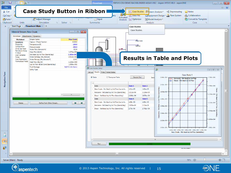
Case Study Button in Ribbon
Drag & Drop Variables Results in Table and Plots
© 2013 Aspen Technology, Inc. All rights reserved |
16
Outline
Overview of HYSYS V8
Compressor Overview
– Types
– What’s Important to Consider
– Surge
Modeling Compressors in HYSYS
– Overview
– Demo
Compressor Trip Case Studies
– Best Practices
– Customer Examples
– AspenTech Global Services & Capabilities
Wrap-Up and Q&A

© 2013 Aspen Technology, Inc. All rights reserved |
17
Poll Question
© 2013 Aspen Technology, Inc. All rights reserved |
18
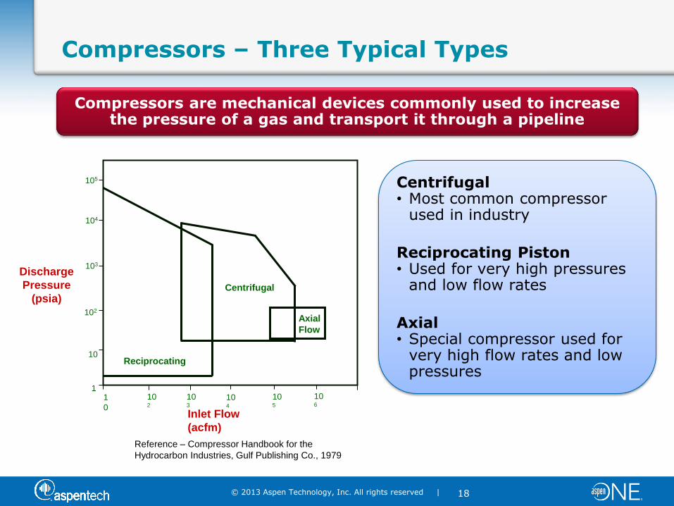
Compressors – Three Typical Types
Centrifugal • Most common compressor
used in industry
Reciprocating Piston • Used for very high pressures
and low flow rates
Axial • Special compressor used for
very high flow rates and low pressures
Inlet Flow
(acfm)
1
0
102
103
104
106
105
1
10
102
105
103
104
Discharge
Pressure
(psia)
Reciprocating
Centrifugal
Axial
Flow
Reference – Compressor Handbook for the
Hydrocarbon Industries, Gulf Publishing Co., 1979
Compressors are mechanical devices commonly used to increase the pressure of a gas and transport it through a pipeline
© 2013 Aspen Technology, Inc. All rights reserved |
19
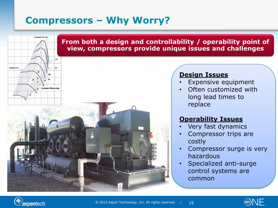
Compressors – Why Worry?
Design Issues • Expensive equipment • Often customized with
long lead times to replace
Operability Issues • Very fast dynamics • Compressor trips are
costly • Compressor surge is very
hazardous • Specialized anti-surge
control systems are common
From both a design and controllability / operability point of view, compressors provide unique issues and challenges
© 2013 Aspen Technology, Inc. All rights reserved |
20
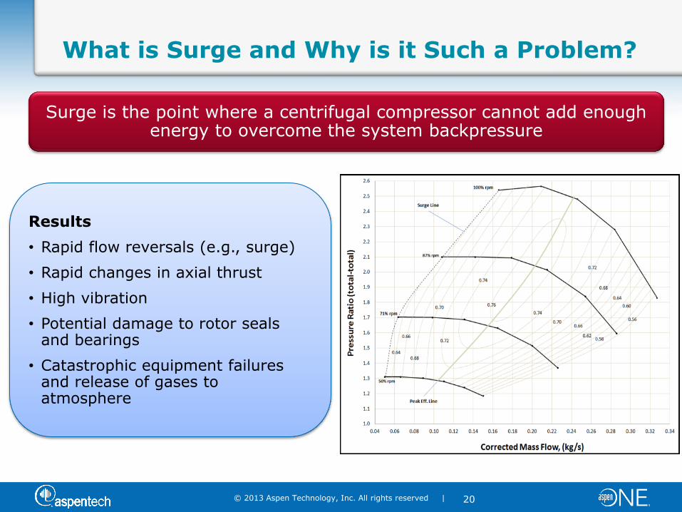
What is Surge and Why is it Such a Problem?
Results
• Rapid flow reversals (e.g., surge)
• Rapid changes in axial thrust
• High vibration
• Potential damage to rotor seals and bearings
• Catastrophic equipment failures and release of gases to atmosphere
Surge is the point where a centrifugal compressor cannot add enough energy to overcome the system backpressure
© 2013 Aspen Technology, Inc. All rights reserved |
21
Outline
Overview of HYSYS V8
Compressor Overview
– Types
– What’s Important to Consider
– Surge
Modeling Compressors in HYSYS
– Overview
– Demo
Compressor Trip Case Studies
– Best Practices
– Customer Examples
– AspenTech Global Services & Capabilities
Wrap-Up and Q&A
© 2013 Aspen Technology, Inc. All rights reserved |
22
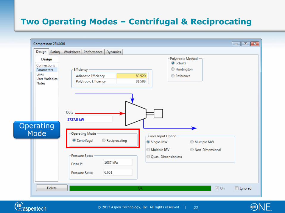
Two Operating Modes – Centrifugal & Reciprocating
Operating Mode
© 2013 Aspen Technology, Inc. All rights reserved |
23
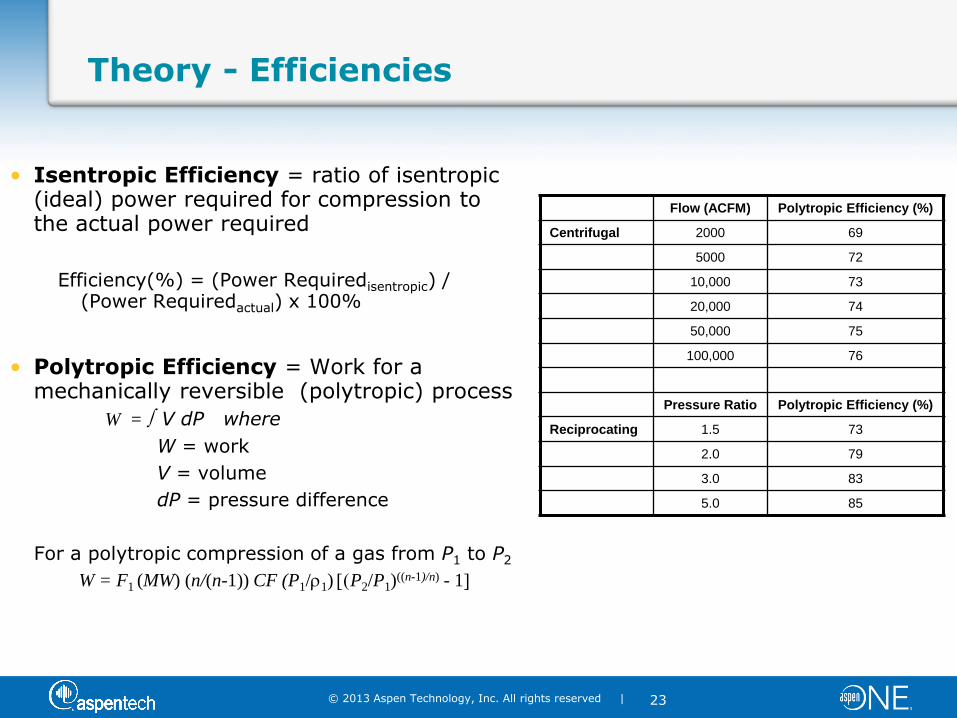
Theory - Efficiencies
• Isentropic Efficiency = ratio of isentropic (ideal) power required for compression to the actual power required
Efficiency(%) = (Power Requiredisentropic) / (Power Requiredactual) x 100%
• Polytropic Efficiency = Work for a mechanically reversible (polytropic) process
W = V dP where
W = work
V = volume
dP = pressure difference
For a polytropic compression of a gas from P1 to P2
W = F1 (MW) (n/(n-1)) CF (P1/r1) (P2/P1)((n-1)/n) - 1]
Flow (ACFM) Polytropic Efficiency (%)
Centrifugal 2000 69
5000 72
10,000 73
20,000 74
50,000 75
100,000 76
Pressure Ratio Polytropic Efficiency (%)
Reciprocating 1.5 73
2.0 79
3.0 83
5.0 85
© 2013 Aspen Technology, Inc. All rights reserved |
24
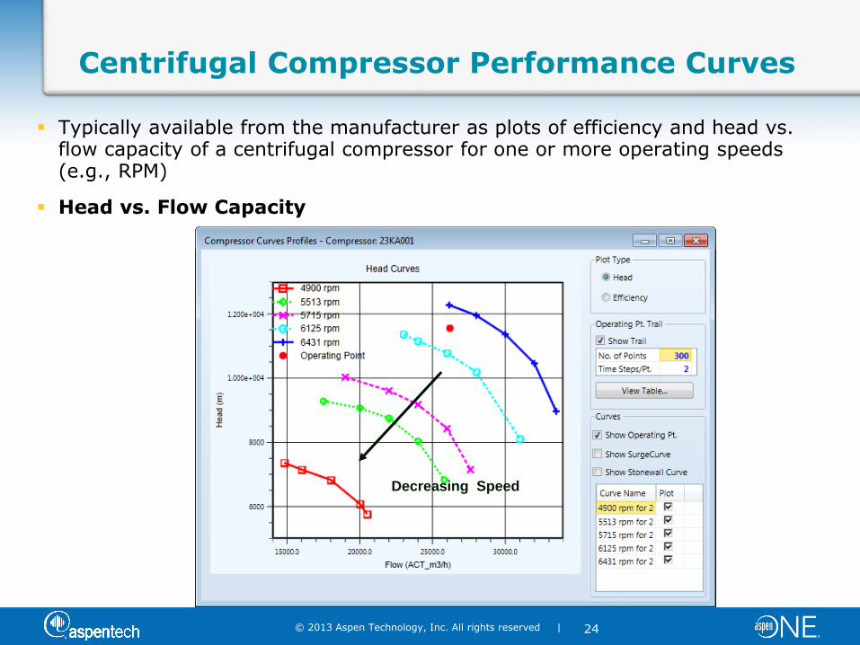
Centrifugal Compressor Performance Curves
Typically available from the manufacturer as plots of efficiency and head vs. flow capacity of a centrifugal compressor for one or more operating speeds (e.g., RPM)
Head vs. Flow Capacity
Decreasing Speed
© 2013 Aspen Technology, Inc. All rights reserved |
25
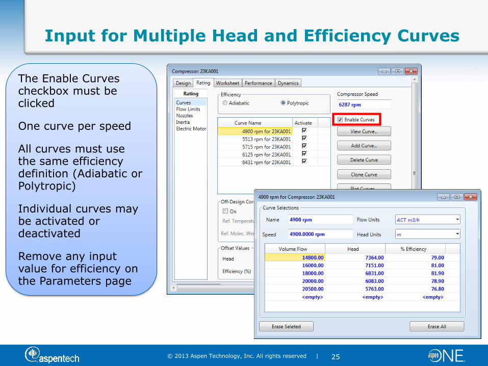
Input for Multiple Head and Efficiency Curves
The Enable Curves checkbox must be clicked
One curve per speed
All curves must use the same efficiency definition (Adiabatic or Polytropic)
Individual curves may be activated or deactivated
Remove any input value for efficiency on the Parameters page
© 2013 Aspen Technology, Inc. All rights reserved |
26
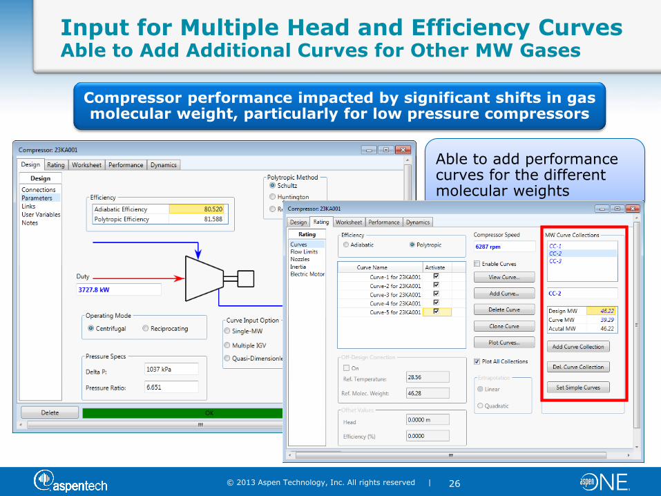
Input for Multiple Head and Efficiency Curves Able to Add Additional Curves for Other MW Gases
Able to add performance curves for the different molecular weights
Compressor performance impacted by significant shifts in gas molecular weight, particularly for low pressure compressors
© 2013 Aspen Technology, Inc. All rights reserved |
27
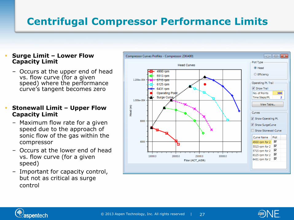
Centrifugal Compressor Performance Limits
Surge Limit – Lower Flow Capacity Limit
– Occurs at the upper end of head vs. flow curve (for a given speed) where the performance curve’s tangent becomes zero
Stonewall Limit – Upper Flow Capacity Limit
– Maximum flow rate for a given speed due to the approach of sonic flow of the gas within the compressor
– Occurs at the lower end of head vs. flow curve (for a given speed)
– Important for capacity control, but not as critical as surge
control
© 2013 Aspen Technology, Inc. All rights reserved |
28
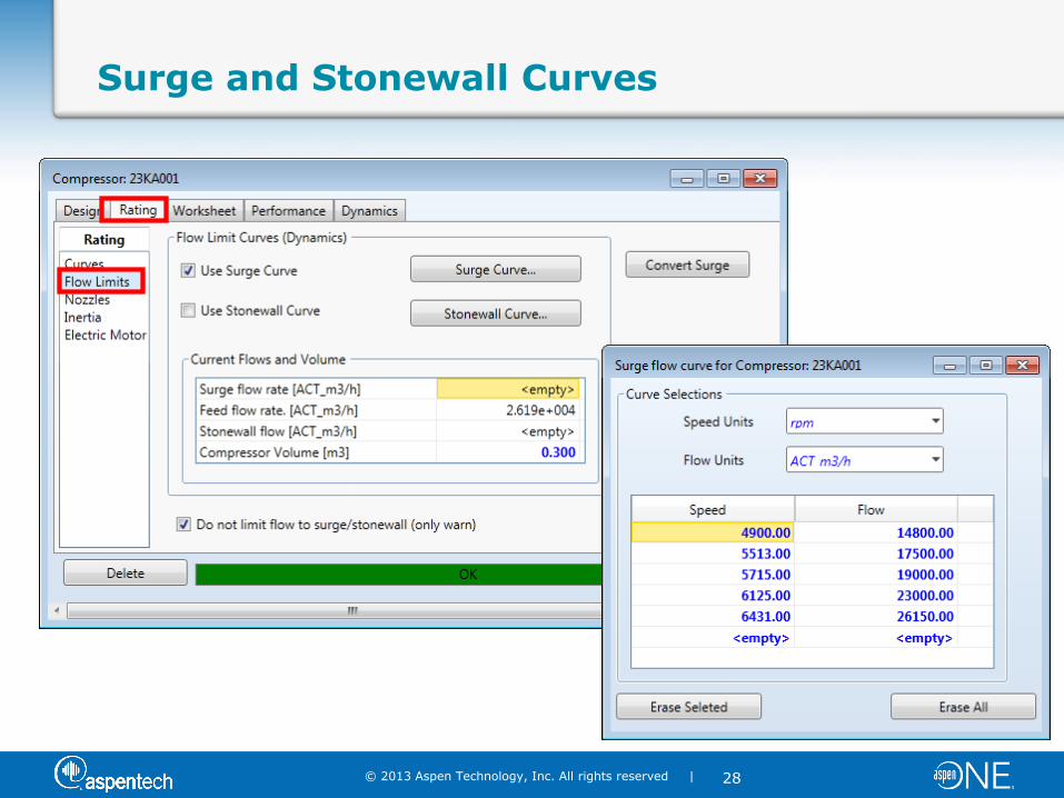
Surge and Stonewall Curves
© 2013 Aspen Technology, Inc. All rights reserved |
29
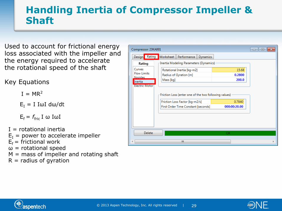
Handling Inertia of Compressor Impeller & Shaft
Used to account for frictional energy loss associated with the impeller and the energy required to accelerate the rotational speed of the shaft Key Equations
I = MR2
EI = I IωI dω/dt Ef = ffric I ω IωI I = rotational inertia EI = power to accelerate impeller Ef = frictional work ω = rotational speed M = mass of impeller and rotating shaft R = radius of gyration
© 2013 Aspen Technology, Inc. All rights reserved |
30
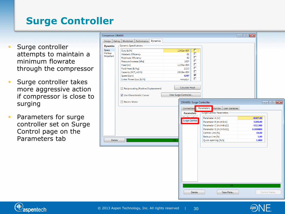
Surge Controller
Surge controller attempts to maintain a minimum flowrate through the compressor
Surge controller takes more aggressive action if compressor is close to surging
Parameters for surge controller set on Surge Control page on the Parameters tab
© 2013 Aspen Technology, Inc. All rights reserved |
31
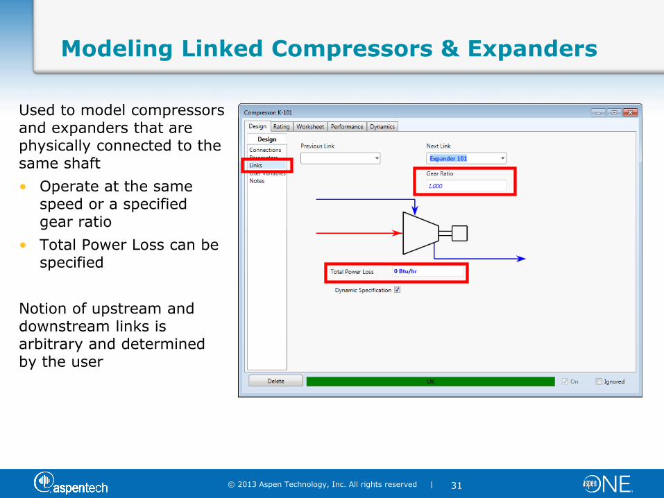
Modeling Linked Compressors & Expanders
Used to model compressors and expanders that are physically connected to the same shaft
• Operate at the same speed or a specified gear ratio
• Total Power Loss can be specified
Notion of upstream and downstream links is arbitrary and determined by the user
© 2013 Aspen Technology, Inc. All rights reserved |
32
Demonstration
© 2013 Aspen Technology, Inc. All rights reserved |
33
Outline
Overview of HYSYS V8
Compressor Overview
– Types
– What’s Important to Consider
– Surge
Modeling Compressors in HYSYS
– Overview
– Demo
Compressor Best Practice & Case Studies
– Best Practices
– Customer Examples
– AspenTech Global Services & Capabilities
Wrap-Up and Q&A
© 2013 Aspen Technology, Inc. All rights reserved |
34
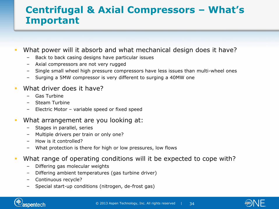
Centrifugal & Axial Compressors – What’s Important
What power will it absorb and what mechanical design does it have? – Back to back casing designs have particular issues
– Axial compressors are not very rugged
– Single small wheel high pressure compressors have less issues than multi-wheel ones
– Surging a 5MW compressor is very different to surging a 40MW one
What driver does it have? – Gas Turbine
– Steam Turbine
– Electric Motor – variable speed or fixed speed
What arrangement are you looking at: – Stages in parallel, series
– Multiple drivers per train or only one?
– How is it controlled?
– What protection is there for high or low pressures, low flows
What range of operating conditions will it be expected to cope with? – Differing gas molecular weights
– Differing ambient temperatures (gas turbine driver)
– Continuous recycle?
– Special start-up conditions (nitrogen, de-frost gas)
© 2013 Aspen Technology, Inc. All rights reserved |
35
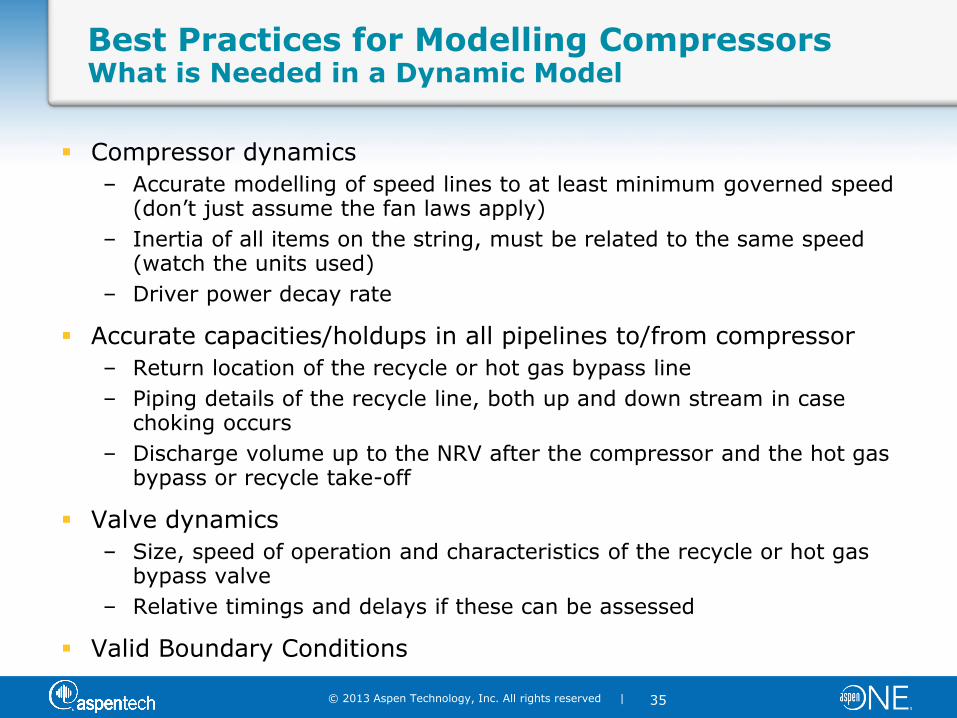
Best Practices for Modelling Compressors What is Needed in a Dynamic Model
Compressor dynamics
– Accurate modelling of speed lines to at least minimum governed speed (don’t just assume the fan laws apply)
– Inertia of all items on the string, must be related to the same speed (watch the units used)
– Driver power decay rate
Accurate capacities/holdups in all pipelines to/from compressor
– Return location of the recycle or hot gas bypass line
– Piping details of the recycle line, both up and down stream in case choking occurs
– Discharge volume up to the NRV after the compressor and the hot gas bypass or recycle take-off
Valve dynamics
– Size, speed of operation and characteristics of the recycle or hot gas bypass valve
– Relative timings and delays if these can be assessed
Valid Boundary Conditions
© 2013 Aspen Technology, Inc. All rights reserved |
36
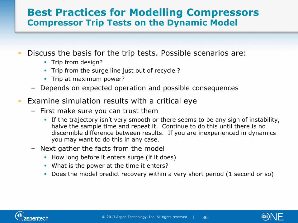
Best Practices for Modelling Compressors Compressor Trip Tests on the Dynamic Model
Discuss the basis for the trip tests. Possible scenarios are: Trip from design?
Trip from the surge line just out of recycle ?
Trip at maximum power?
– Depends on expected operation and possible consequences
Examine simulation results with a critical eye
– First make sure you can trust them
If the trajectory isn’t very smooth or there seems to be any sign of instability, halve the sample time and repeat it. Continue to do this until there is no discernible difference between results. If you are inexperienced in dynamics you may want to do this in any case.
– Next gather the facts from the model
How long before it enters surge (if it does)
What is the power at the time it enters?
Does the model predict recovery within a very short period (1 second or so)
© 2013 Aspen Technology, Inc. All rights reserved |
37
Best Practices for Modelling Compressors Modelling the Compressor under Surge Conditions
The only details you can rely on are the time and power of entry into surge
– No commercially available dynamic compressor model accurately predicts behavior in surge
You may draw some tentative conclusions from the time spent in surge according to the model
– Less than 0.5 seconds on a HYSYS Dynamics model is often unlikely to be real based on feedback from operations
Always discuss with the Compressor Vendor, in the end it is their decision on whether action needs to be taken
Ideally surge should be totally prevented in all cases
© 2013 Aspen Technology, Inc. All rights reserved |
38
Best Practices for Modelling Compressors Possible Design Changes to Avoid Surge
Minimize the discharge volume
Increase the recycle valve size (within the limits of controllability)
Increase the speed of opening of the recycle valve
Consider a parallel cold gas bypass valve around the recycle valve
Consider a hot gas bypass valve
– Considerations such as leakage, vibration etc. often make this an unattractive option
© 2013 Aspen Technology, Inc. All rights reserved |
39
Best Practices for Modelling Compressors Modelling the Anti-Surge Control System
Surge control systems are designed to detect the imminent start of surging, and prevent the compressor from reaching this operating condition
Basic Strategy – Open a surge recycle valve that will allow outlet flow from the compressor to recycle back to the compressor inlet, thus providing a flow rate through the compressor above the minimum surge limit.
For conceptual and FEED studies, use the HYSYS Anti-Surge controller
For detailed design, there may be a need to use a proprietary system:
– CCC, Dresser Rand, Man-Turbo, Solar, Triconex etc
Most of these systems use multiple control lines, linking between serial and parallel units, surge protection by moving lines, various characterizers, algorithm selection etc. and can be quite complex to set up
In some cases the Vendor will provide software (at a cost) or an emulator; in others just the algorithms are used and settings
© 2013 Aspen Technology, Inc. All rights reserved |
40
Challenge Solution Results Challenge
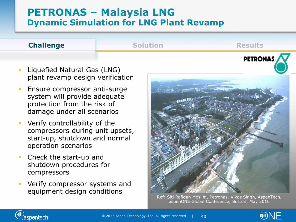
Liquefied Natural Gas (LNG) plant revamp design verification
Ensure compressor anti-surge system will provide adequate protection from the risk of damage under all scenarios
Verify controllability of the compressors during unit upsets, start-up, shutdown and normal operation scenarios
Check the start-up and shutdown procedures for compressors
Verify compressor systems and equipment design conditions
Ref: Siti Rafidah Moslim, Petronas, Vikas Singh, AspenTech, aspenONE Global Conference, Boston, May 2010
PETRONAS – Malaysia LNG Dynamic Simulation for LNG Plant Revamp
© 2013 Aspen Technology, Inc. All rights reserved |
41
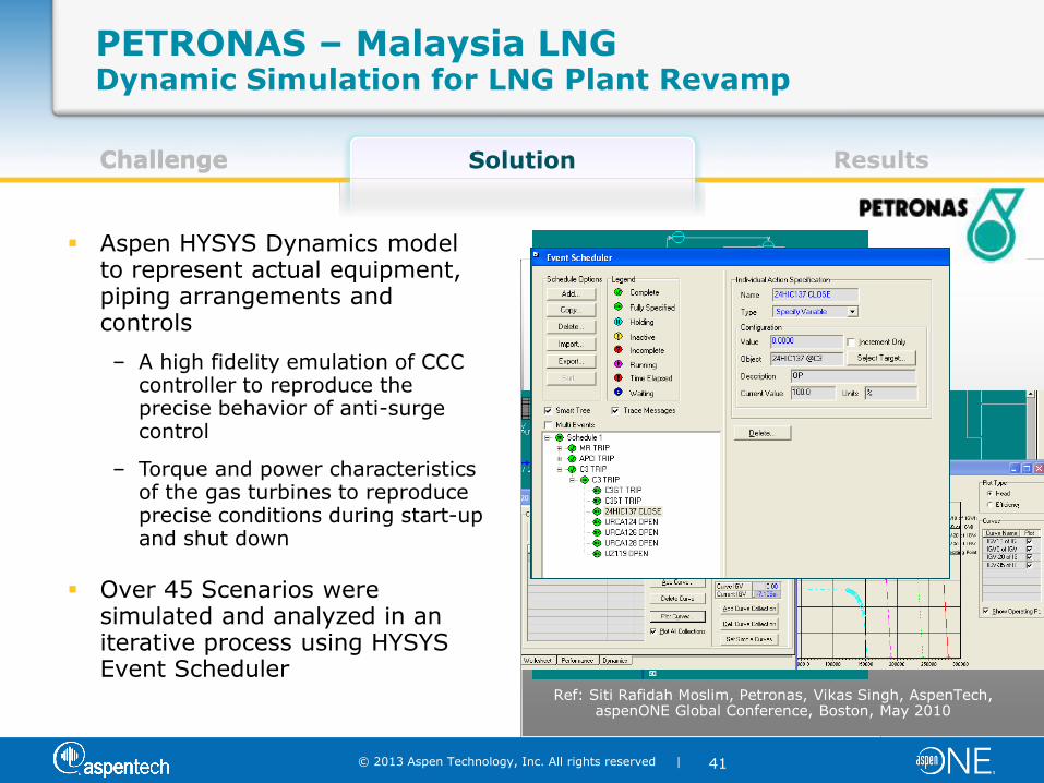
Challenge Solution Results
PETRONAS – Malaysia LNG Dynamic Simulation for LNG Plant Revamp
Challenge
Aspen HYSYS Dynamics model to represent actual equipment, piping arrangements and controls
– A high fidelity emulation of CCC controller to reproduce the precise behavior of anti-surge control
– Torque and power characteristics of the gas turbines to reproduce precise conditions during start-up and shut down
Over 45 Scenarios were simulated and analyzed in an iterative process using HYSYS Event Scheduler
Ref: Siti Rafidah Moslim, Petronas, Vikas Singh, AspenTech, aspenONE Global Conference, Boston, May 2010
© 2013 Aspen Technology, Inc. All rights reserved |
42
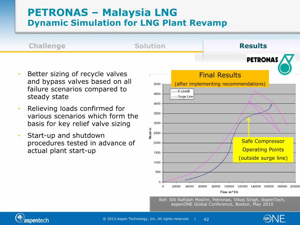
Challenge Solution Results
PETRONAS – Malaysia LNG Dynamic Simulation for LNG Plant Revamp
Challenge
• Better sizing of recycle valves and bypass valves based on all failure scenarios compared to steady state
• Relieving loads confirmed for various scenarios which form the basis for key relief valve sizing
• Start-up and shutdown procedures tested in advance of actual plant start-up
Safe Compressor
Operating Points
(outside surge line)
Final Results
(after implementing recommendations)
Ref: Siti Rafidah Moslim, Petronas, Vikas Singh, AspenTech, aspenONE Global Conference, Boston, May 2010
© 2013 Aspen Technology, Inc. All rights reserved |
43
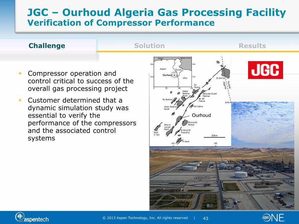
Challenge Solution Results Challenge
Compressor operation and control critical to success of the overall gas processing project
Customer determined that a dynamic simulation study was essential to verify the performance of the compressors and the associated control systems
JGC – Ourhoud Algeria Gas Processing Facility Verification of Compressor Performance
© 2013 Aspen Technology, Inc. All rights reserved |
44
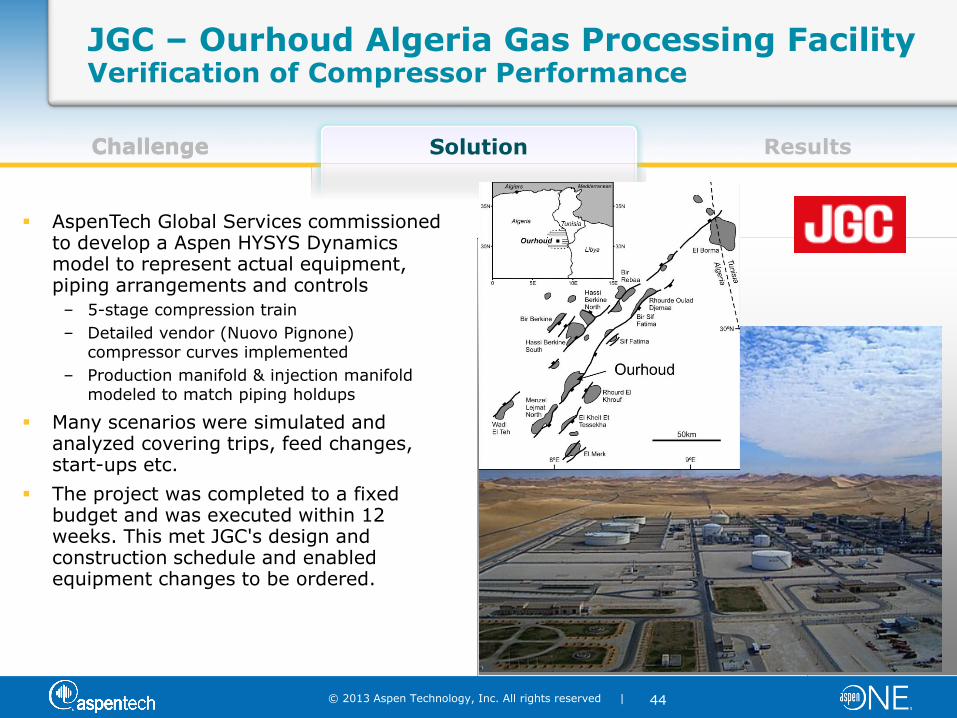
Challenge Solution Results
JGC – Ourhoud Algeria Gas Processing Facility Verification of Compressor Performance
Challenge
AspenTech Global Services commissioned to develop a Aspen HYSYS Dynamics model to represent actual equipment, piping arrangements and controls
– 5-stage compression train
– Detailed vendor (Nuovo Pignone) compressor curves implemented
– Production manifold & injection manifold modeled to match piping holdups
Many scenarios were simulated and analyzed covering trips, feed changes, start-ups etc.
The project was completed to a fixed budget and was executed within 12 weeks. This met JGC's design and construction schedule and enabled equipment changes to be ordered.
© 2013 Aspen Technology, Inc. All rights reserved |
45
Challenge Solution Results
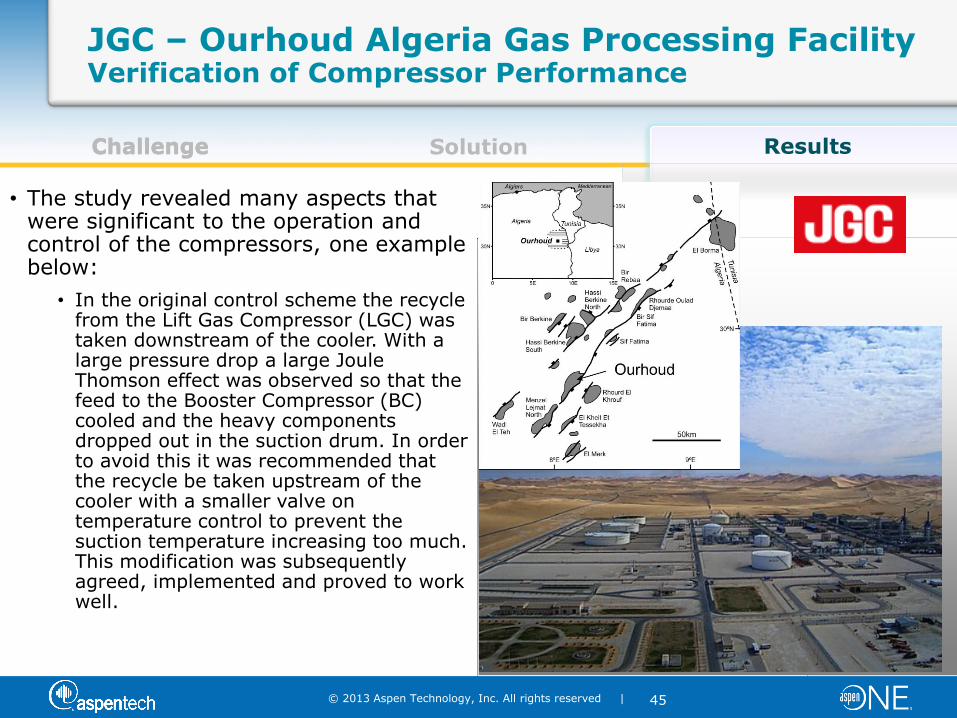
JGC – Ourhoud Algeria Gas Processing Facility Verification of Compressor Performance
Challenge
• The study revealed many aspects that were significant to the operation and control of the compressors, one example below:
• In the original control scheme the recycle from the Lift Gas Compressor (LGC) was taken downstream of the cooler. With a large pressure drop a large Joule Thomson effect was observed so that the feed to the Booster Compressor (BC) cooled and the heavy components dropped out in the suction drum. In order to avoid this it was recommended that the recycle be taken upstream of the cooler with a smaller valve on temperature control to prevent the suction temperature increasing too much. This modification was subsequently agreed, implemented and proved to work well.
© 2013 Aspen Technology, Inc. All rights reserved |
46
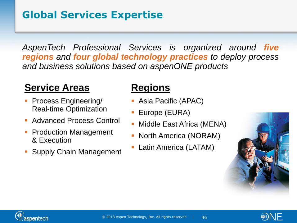
Global Services Expertise
AspenTech Professional Services is organized around five regions and four global technology practices to deploy process and business solutions based on aspenONE products
Service Areas
Process Engineering/ Real-time Optimization
Advanced Process Control
Production Management & Execution
Supply Chain Management
Regions
Asia Pacific (APAC)
Europe (EURA)
Middle East Africa (MENA)
North America (NORAM)
Latin America (LATAM)
© 2013 Aspen Technology, Inc. All rights reserved |
47
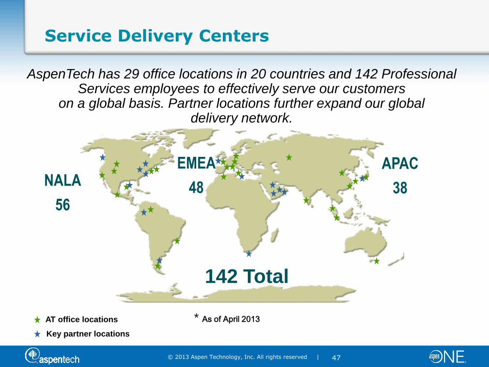
AspenTech has 29 office locations in 20 countries and 142 Professional Services employees to effectively serve our customers
on a global basis. Partner locations further expand our global delivery network.
NALA
56
EMEA
48
APAC
38
142 Total
* As of April 2013 AT office locations
Key partner locations
Service Delivery Centers
© 2013 Aspen Technology, Inc. All rights reserved |
48
Outline
Overview of HYSYS V8
Compressor Overview
– Types
– What’s Important to Consider
– Surge
Modeling Compressors in HYSYS
– Overview
– Demo
Compressor Trip Case Studies
– Best Practices
– Customer Examples
– AspenTech Global Services & Capabilities
Wrap-Up and Q&A
© 2013 Aspen Technology, Inc. All rights reserved |
49
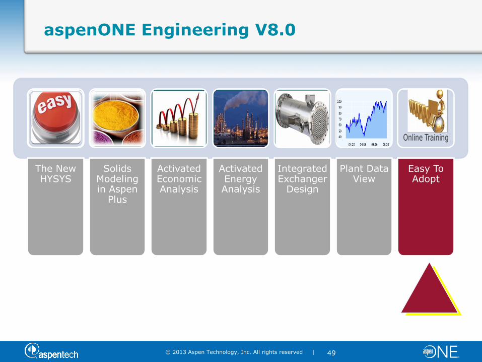
aspenONE Engineering V8.0
The New HYSYS
Solids Modeling in Aspen
Plus
Activated Economic Analysis
Activated Energy Analysis
Integrated Exchanger
Design
Plant Data View
Easy To Adopt
© 2013 Aspen Technology, Inc. All rights reserved |
50
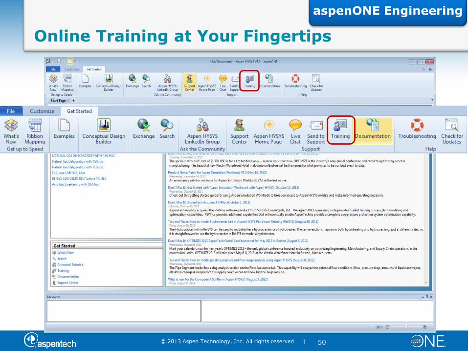
Online Training at Your Fingertips
aspenONE Engineering
© 2013 Aspen Technology, Inc. All rights reserved |
51
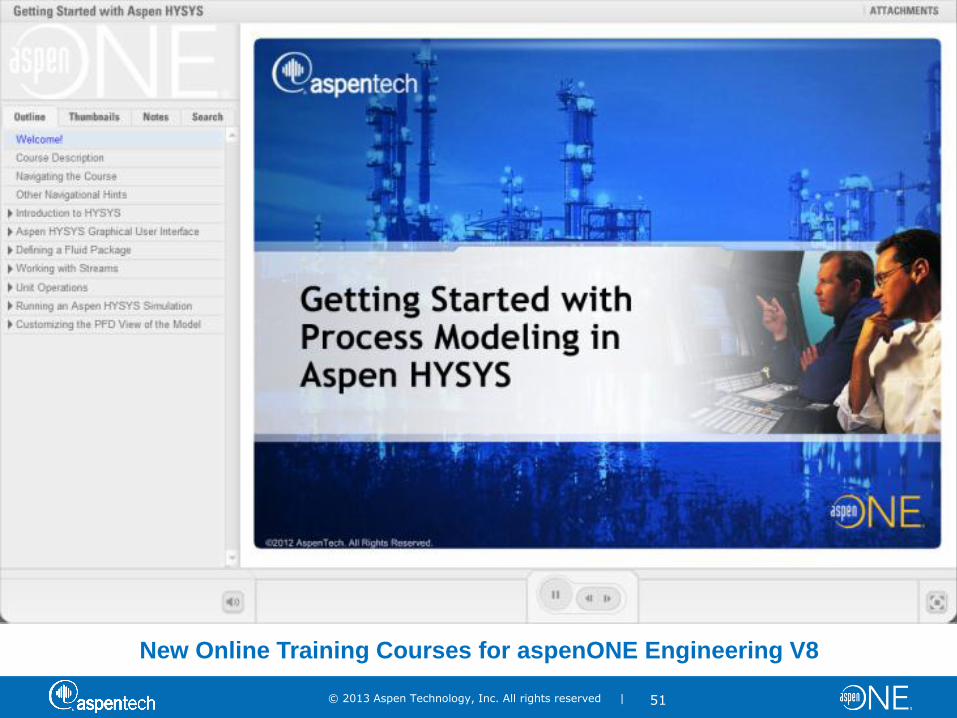
New Online Training Courses for aspenONE Engineering V8

© 2013 Aspen Technology, Inc. All rights reserved |
53
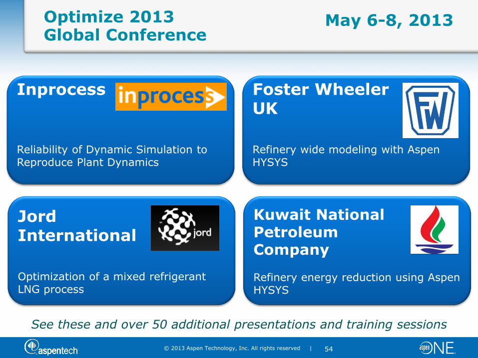
OPTIMIZE™ 2013 Global Conference
Join us in Boston for the industry’s must-attend event!
OPTIMIZE 2013 6 – 8 May 2013
The Westin Waterfront Hotel
Boston, MA USA
For more information, visit www.aspentech.com/agc
© 2013 Aspen Technology, Inc. All rights reserved |
54
Optimize 2013 Global Conference
Foster Wheeler UK Refinery wide modeling with Aspen HYSYS
Jord International Optimization of a mixed refrigerant LNG process
Kuwait National Petroleum Company Refinery energy reduction using Aspen HYSYS
May 6-8, 2013
See these and over 50 additional presentations and training sessions
Inprocess Reliability of Dynamic Simulation to Reproduce Plant Dynamics

© 2013 Aspen Technology, Inc. All rights reserved |
55
What Next?
Get more information now
– Additional resources available at:
http://www.aspentech.com/products/aspen-hysys.aspx
http://www.aspentech.com/products/aspen-hysys-dynamics.aspx
– Videos also available at: www.youtube.com/user/aspentechnologyinc
Contact info for today’s presenters and hosts – Glenn Dissinger [email protected]
– Martyn Blanchard [email protected]
– Luisa Herrmann [email protected]
– Ron Beck [email protected]

© 2013 Aspen Technology, Inc. All rights reserved |
56
Questions?