Embed Size (px)
Citation preview

ASPECT ORIENTED PROGRAMMING
MEETS DESIGN PATTERNS
A dissertation submitted to The University of Manchester for the degree of
Master of Science in the Faculty of Engineering and Physical Sciences
2013
GUILLERMO A. TORO BAYONA
SCHOOL OF COMPUTER SCIENCE

2
List of Contents
ABSTRACT ............................................................................................................ 8
DECLARATION ....................................................................................................... 9
INTELLECTUAL PROPERTY STATEMENT .................................................................. 10
1 INTRODUCTION ............................................................................................. 11
1.1 Project Objectives ................................................................................ 11
1.2 Dissertation Overview ......................................................................... 12
2 BACKGROUND .............................................................................................. 14
2.1 Object Oriented Programming ............................................................. 14
2.2 Design Patterns ................................................................................... 15
2.3 Object Oriented Programming and Design Pattern Issues .................. 15
2.4 A Simple Application with OOP ........................................................... 16
2.4.1 The Observer Pattern ................................................................... 17
2.4.2 Code Implementation ................................................................... 19
2.4.3 Issues Analysis ............................................................................. 22
2.5 Aspect Oriented Programming ............................................................ 24
2.5.1 Relevant Concepts ....................................................................... 24
2.5.2 Development Process with Aspects .............................................. 25
2.6 A Simple Example with AOP ............................................................... 26
2.6.1 Code Implementation ................................................................... 26
2.6.2 Simple Scenario Analysis ............................................................. 27
2.7 The Aspect Oriented Paradigm and Software Development ............... 29
2.7.1 AOP and Software Development Process .................................... 29
2.7.2 Development ................................................................................ 29
2.7.3 Testing .......................................................................................... 30
2.7.4 Unified Modelling Language and AOP .......................................... 30
2.7.5 Design Patterns ............................................................................ 31
3 RESEARCH METHODS ................................................................................... 33
3.1 Aspect Oriented Programming meets Design Patterns ....................... 33
3.2 Metrics ................................................................................................ 33
3.3 Aspect J (Aspect Implementation for Java) ......................................... 35
3.4 Project Methodology ........................................................................... 36

3
3.4.1 Explore a subset of the patterns to apply. ..................................... 36
3.4.2 Develop an application using OOP and AOP. ............................... 36
3.4.3 Assess and review the metrics. .................................................... 37
3.4.4 Identify advantages and disadvantages of AOP. ........................... 37
3.4.5 Document the results. ................................................................... 37
4 THE OBSERVER PATTERN ............................................................................. 38
4.1 Business Scenario .............................................................................. 38
4.2 AOP Implementation ........................................................................... 38
4.3 Metrics ................................................................................................ 41
4.4 Metrics Analysis .................................................................................. 43
4.5 Conclusions ......................................................................................... 46
5 THE COMPOSITE, ADAPTER AND PROXY PATTERNS ......................................... 48
5.1 Business Scenarios ............................................................................. 48
5.2 The Composite Pattern ....................................................................... 49
5.2.1 OOP Approach ............................................................................. 49
5.2.2 AOP Approach .............................................................................. 51
5.3 The Adapter Pattern ............................................................................ 53
5.3.1 OOP Approach ............................................................................. 53
5.3.2 AOP Approach .............................................................................. 54
5.4 The Proxy Pattern ............................................................................... 55
5.4.1 OOP Approach ............................................................................. 55
5.4.2 AOP Approach .............................................................................. 56
5.5 Metrics Analysis .................................................................................. 58
5.6 Conclusions ......................................................................................... 61
6 THE COMMAND, STRATEGY AND TEMPLATE PATTERNS .................................... 64
6.1 Business Scenarios ............................................................................. 64
6.2 The Command Pattern ........................................................................ 65
6.2.1 OOP Approach ............................................................................. 65
6.2.2 AOP Approach .............................................................................. 66
6.3 The Strategy Pattern ........................................................................... 68
6.3.1 OOP Approach ............................................................................. 68
6.3.2 AOP Approach .............................................................................. 69
6.4 The Template Pattern .......................................................................... 70
6.4.1 OOP Approach ............................................................................. 70
6.4.2 AOP Approach .............................................................................. 71

4
6.5 Metrics Analysis .................................................................................. 72
6.6 Conclusions ......................................................................................... 75
7 THE ABSTRACT FACTORY AND SINGLETON PATTERNS ..................................... 78
7.1 Business Scenarios ............................................................................. 78
7.2 The Abstract Factory Pattern ............................................................... 78
7.2.1 OOP Approach ............................................................................. 78
7.2.2 AOP Approach .............................................................................. 80
7.3 The Singleton Pattern ......................................................................... 81
7.3.1 OOP Approach ............................................................................. 81
7.3.2 AOP Approach .............................................................................. 83
7.4 Metrics Analysis .................................................................................. 84
7.5 Conclusions ......................................................................................... 86
8 PATTERN INTERACTIONS ............................................................................... 88
8.1 Overview ............................................................................................. 88
8.2 Pattern Dependencies ......................................................................... 88
8.2.1 Strategy and Observer patterns .................................................... 88
8.2.2 Abstract Factory and Singleton patterns ....................................... 90
8.2.3 Template and Proxy patterns ........................................................ 90
8.2.4 Composite pattern ........................................................................ 91
8.3 Domain Classes .................................................................................. 93
8.3.1 Monitoring Stations ....................................................................... 93
8.3.2 Local and Remote Stations ........................................................... 94
9 CONCLUSIONS AND FUTURE WORK ................................................................ 95
9.1 Conclusions ......................................................................................... 95
9.2 Recommendations .............................................................................. 97
9.3 Future Work ........................................................................................ 98
10 REFERENCES ............................................................................................. 102
APPENDIX A: METRICS RESULTS ........................................................................ 107
Word Count: 22487
5
List of Figures
Figure 2-1. Observer Pattern for the Security System using OOP. ............................... 18
Figure 2-2. Observer Class. .......................................................................................... 19
Figure 2-3. Monitoring Station class extending Observer. ............................................ 19
Figure 2-4. Remote Station extending Monitoring Station. ........................................... 20
Figure 2-5. Subject Interface definition. ........................................................................ 20
Figure 2-6. Camera class extending Device class and implementing Subject. ............ 21
Figure 2-7. Concrete implementation of operations: Add and Remove Observer. ........ 21
Figure 2-8. Concrete implementation of the operation Notify Observer. ....................... 22
Figure 2-9. An OOP approach to solve the logging operations of a Room Sensor. ...... 26
Figure 2-10. Aspect implementing the logging requirement for the Room Sensor........ 27
Figure 2-11. The Security System modifying a Room Sensor. ..................................... 28
Figure 2-12. Output generated by the Aspect in the advice implementations. ............. 28
Figure 2-13. Aspect UML representing the Logging requirement. ................................ 31
Figure 4-1. Observer pattern for the Security System using AOP. ................................ 39
Figure 4-2. Remote Station Aspect for the Security System. ........................................ 39
Figure 5-1. Composite pattern for the Security System using OOP. ............................. 50
Figure 5-2. Composite pattern for the Security System using AOP. ............................. 52
Figure 5-3. Adapter pattern for the Security System using OOP. .................................. 53
Figure 5-4. Adapter pattern for the Security System using AOP. .................................. 55
Figure 5-5. Proxy pattern for the Security System using OOP. ..................................... 56
Figure 5-6. Proxy pattern for the Security System using AOP. ..................................... 57
Figure 6-1. Command pattern for the Security System using OOP. ............................. 66
Figure 6-2. Command pattern for the Security System using AOP. .............................. 67
Figure 6-3. Strategy pattern for the Security System using OOP. ................................. 68
Figure 6-4. Strategy pattern for the Security System using AOP. ................................. 69
Figure 6-5. Template pattern for the Security System using OOP. ............................... 70
Figure 6-6. Template pattern for the Security System using AOP. ................................ 71
Figure 7-1. Abstract Factory pattern for the Security System using OOP. .................... 79
Figure 7-2. Abstract Factory pattern for the Security System using AOP. ..................... 80
Figure 7-3. Singleton pattern for the Security System using OOP. ............................... 81
Figure 7-4. Singleton approach using OOP. ................................................................. 82
Figure 7-5. Singleton pattern for the Security System using AOP. ................................ 83
Figure 7-6. Marking classes with the Singleton interface in the aspect. ....................... 84

6
Figure 8-1. Modifying the list of observers with the OOP approach. ............................. 88
Figure 8-2. Modifying the list of observers with the AOP approach. ............................. 89
Figure 8-3. Accessing children devices of the Device Group with OOP. ....................... 91
Figure 8-4. Accessing children devices of the Device Group with AOP. ....................... 92
Figure A-1. Bars diagram with the CDC metric. .......................................................... 107
Figure A-2. Bars diagram with the CDO metric. .......................................................... 108
Figure A-3. Bars diagram with the CDLOC metric. ..................................................... 109
Figure A-4. Bars diagram with the CBC metric. .......................................................... 110
Figure A-5. Bars diagram with the LOC metric. ........................................................... 111
Figure A-6. Bars diagram with the NOA metric. .......................................................... 112

7
List of Tables
Table 3-1. The Metrics Suite. ........................................................................................ 34
Table 4-1. Assessment guidelines for the metrics suite. ............................................... 42
Table 4-2. Metrics results for the Observer patterns. .................................................... 43
Table 5-1. Metrics results for the Composite, Adapter and Proxy patterns. .................. 58
Table 6-1. Metrics results for the Command, Strategy and Template patterns. ............ 72
Table 7-1. Metrics results for the Abstract Factory and Singleton patterns. .................. 85
Table A-1. Concern Diffusion over Components (CDC metric). .................................. 107
Table A-2. Concern Diffusion over Operations (CDO metric). ..................................... 108
Table A-3. Concern Diffusions over LOC (CDLOC). ................................................... 109
Table A-4. Coupling Between Components (CBC) ..................................................... 110
Table A-5. Lines of Code (LOC) ................................................................................... 111
Table A-6. Number of Attributes (NOA). ...................................................................... 112
Table A-7. Depth of the Inheritance Tree (DIT metric). ............................................... 114
Table A-8. Lack of Cohesion over Operations (LCOO metric). ................................... 116
8
ABSTRACT
Object Oriented Programming (OOP) is a programming paradigm that has
been used for several years by the software engineering community. Some of
the best practices of OOP have been gathered to provide guidelines for
developing flexible software applications. These practices are known as Design
Patterns. Recent studies claim that some patterns have limitations and their
implementations could be improved. Researchers claim that Aspect Oriented
Programming (AOP) is a paradigm that provides features to overcome the
limitations of OOP and patterns. However, it is possible to cause side effects in
code by using AOP. This MSc project implements a subset of the design
patterns with AOP and identifies merits and demerits in comparison with the
traditional OOP implementations.
The AOP approach improves some features in the implementation of the
patterns. This approach localises the pattern code in a common place,
improving reusability and maintenance for some patterns. However, in most of
the cases the coupling increases and the pattern logic inside aspects is not
easy to understand. In addition to that, the values of some evaluated metrics
with AOP are similar to those for the OOP approach without any significant
difference.

9
DECLARATION
No portion of the work referred to in the dissertation has been submitted in
support of an application for another degree or qualification of this or any other
university or other institute of learning.

10
INTELLECTUAL PROPERTY STATEMENT
i. The author of this dissertation (including any appendices and/or
schedules to this dissertation) owns certain copyright or related rights
in it (the “Copyright”) and s/he has given The University of Manchester
certain rights to use such Copyright, including for administrative
purposes.
ii. Copies of this dissertation, either in full or in extracts and whether in
hard or electronic copy, may be made only in accordance with the
Copyright, Designs and Patents Act 1988 (as amended) and
regulations issued under it or, where appropriate, in accordance with
licensing agreements which the University has entered into. This page
must form part of any such copies made.
iii. The ownership of certain Copyright, patents, designs, trademarks and
other intellectual property (the “Intellectual Property”) and any
reproductions of copyright works in the dissertation, for example
graphs and tables (“Reproductions”), which may be described in this
dissertation, may not be owned by the author and may be owned by
third parties. Such Intellectual Property and Reproductions cannot and
must not be made available for use without the prior written
permission of the owner(s) of the relevant Intellectual Property and/or
Reproductions.
iv. Further information on the conditions under which disclosure,
publication and commercialisation of this dissertation, the Copyright
and any Intellectual Property and/or Reproductions described in it may
take place is available in the University IP Policy (see
http://documents.manchester.ac.uk/display.aspx?DocID=487), in any
relevant Dissertation restriction declarations deposited in the
University Library, The University Library’s regulations (see
http://www.manchester.ac.uk/library/aboutus/regulations) and in The
University’s Guidance for the Presentation of Dissertations.

11
1 INTRODUCTION
Object Oriented Programming (OOP) is a well known programming paradigm
in the software industry. The level of maturity of OOP allows software
developers to create flexible and reusable applications [1].
In addition to that, many OOP best practices have been collected in a
catalogue called design patterns. They offer suitable ways to implement
software, keeping the principles of OOP such as reusability, high cohesion, low
coupling and others [2].
However, researchers claim that some patterns could be improved using
Aspect Oriented Programming (AOP) [3]. This is a programming paradigm that
emerged at the end of the 1990s as a complement to OOP [4]. Investigating the
combination of AOP and design patterns is the main motivation of this project.
1.1 Project Objectives
The structure of this project in terms of the aim, the specific objectives and
the deliverables is presented as follows:
Aim of the Project
• Apply AOP to design patterns and identify its impact on pattern
implementation.
Specific Objectives
• Develop an application implementing a subset of the patterns with OOP
and AOP.
• Identify specific measures and methods to assess the OOP and AOP
patterns.
• Describe the advantages and disadvantages of implementing patterns
with AOP.

12
Deliverables
• Software application with the implementation of patterns with OOP and
AOP.
• Development of metrics to assess the OOP and AOP approach.
The main deliverable is the code that shows an OOP and AOP
implementations of some design patterns. Additionally to the code, a list of
metrics is presented in order to support conclusions.
Previous research concluded that AspectJ is a suitable implementation to
develop applications with AOP for Java in terms of documentation, stability and
continuing improvements in the core language [5]. Based on the results of that
research, the project is developed with AspectJ.
1.2 Dissertation Overview
The structure of this document is as follows:
Chapter 2 – Background: This chapter contains information about the topics
related to the project. First, it provides an overview of OOP and design patterns.
After that, all the basic information about AOP is given. These concepts are
illustrated with an example by using the well known Observer pattern.
Chapter 3 – Research Methods: This chapter gives the aim of the project, the
specific objectives and the methodology applied.
Chapter 4 – The Observer Pattern: This chapter gives a complete
explanation of the implementation of this pattern by using AOP. The
implementation with OOP is given in the Chapter 2 as an example. This chapter
shows the metrics results and presents the conclusion of both pattern
implementations.

13
Chapters 5, 6 and 7 – Pattern implementations: These chapters give a
detailed explanation of the OOP and AOP implementations of the patterns
selected. These chapters present the conclusions and the metrics results for
each group of patterns.
Chapter 8 – Pattern Interactions: This chapter analyses the interactions
between patterns and domain classes in the AOP implementations.
Chapter 9 – Conclusions: This chapter draws the conclusions based on the
analysis of the metrics and the implementation process of the patterns by using
AOP.

14
2 BACKGROUND
This chapter gives an overview of the concepts and topics related to the
project. It offers general information on the areas involved, but is not an
extensive explanation of them. Additionally, it presents relevant studies on these
areas of research to set the context of the project. This chapter assumes that
the reader knows the software engineering discipline, but a high level of
expertise is not required. An overview of each topic is given, followed by
information relevant to the project.
2.1 Object Oriented Programming
A process to develop a software application based on user requirements is
called a software development process. Object oriented analysis and design are
techniques applied in this process. They lead software designers to think about
abstract concepts from the domain and represent them as objects [1].
The result of analysing and designing the domain is usually a set of
diagrams, useful to present the relationships between classes and how they
interact [2]. The next step is implementing the user requirements in an
appropriate programming language. The implementation of code must follow
the decisions and constraints from the design.
Object Oriented Programming (OOP) is one of the most well known
paradigms in programming languages. This paradigm works with classes as
abstract concepts in order to perform business logic and data manipulation [6].
Furthermore, one of the key characteristics of OOP is the way in which
classes interact to solve problems [1]. It provides features in order to implement
a variety of relationships such as inheritance and encapsulation. Good software
applications make use of them, in order to support principles of object oriented
analysis such as good assignation of responsibilities, high cohesion and low
coupling. The set of principles is called General Responsibility Assignment
Software Patterns (GRASP) [1].

15
In some cases, complex relationships and specific interactions between
classes are identified in a design model. There are useful ways to create
relationships among classes, in order to adhere to the GRASP principles. Those
special relationships and design approaches have been gathered and they are
called design patterns.
2.2 Design Patterns
These are well known best practices in object oriented design [2]. Patterns
solve specific problems in terms of behaviour and relationships among classes
by using the features of OOP [1]. One of the main objectives of patterns is to
provide software engineers with diverse ways to design specific software
scenarios. In fact, they promote the GRASP principles in software applications.
Patterns have been used for several years in software industry [2]. However,
researchers claim that some of the patterns have issues that could be
overcome by combining other technologies with OOP [3].
2.3 Object Oriented Programming and Design Pattern Issues
Despite the benefits offered by design patterns, there are characteristics of
OOP that are considered not ideal when a software application is being
developed. The foundations of patterns are OOP and GRASP principles [7], but
researchers claim that the limitations of OOP have effects in their
implementation [3].
One of the limitations is managing specific requirements located among
classes. These requirements are called cross-cutting concerns, because they
are not easily separable and require multiple occurrences in code [8].
The problem with these concerns is that the code created to solve them is
mixed with the code in charge of business logic [9]. Examples of these concerns
are logging operations, security validations, auditing operations, monitoring
object behaviour, data validation, exceptions handling and others.

16
In addition to that, another problem with OOP patterns is the scattering and
tangling of code [5]. These effects are present when the code for a specific
requirement (usually a cross-cutting concern), is spread among classes
(scatter) and mixed with code created for other functionalities (tangle). This kind
of code is difficult to maintain [10].
In terms of language implementations, some OOP languages impose
additional constraints. For example, C++ is an object oriented language that
allows multiple inheritance. On the other hand, Java and C# are languages that
restrict direct inheritance to a single class, and implement multiple inheritance
only through interface definitions [11].
Moreover, most patterns require hierarchical relationships between classes
[7], but when classes are participating in more than one pattern or they have
another hierarchical relationship, the implementation of the pattern is not
straightforward and clear [3]. In these cases, software engineers sometimes
implement multiple inheritance by changing slightly the pattern.
Previous studies claim that some characteristics of patterns produce
undesirable effects in code. For example, patterns can be considered invasive,
because they add code (properties and methods) in classes that are
participating in them, and that code is not part of the original class [12].
Locality and reusability are considered as issues for some patterns. If the
number of instances of the patterns is large, the pattern code is replicated in a
large number of classes, meaning that the maintenance is difficult [13].
Therefore, the pattern is not reusable because its code is not located in a
centralised place [3].
2.4 A Simple Application with OOP
The best way to explain the previous concepts such as design patterns, OOP
implementation and possible issues is by showing an example.

17
The following example is taken and modified from the lecture notes of the
academic course called Pattern-Based Software Development developed and
taught by Dr. John Sargeant, who is the supervisor of this project.
A Security System is described as follows: A building has a collection of
electronic Devices. The system needs to keep record about the electrical safety
test of all the Devices in the building. In addition to that, there are Monitoring
Stations that keep track of all the events that happen in the building. Some
Devices are able to provide information (events) about the places where they
are located such as Cameras, Room Sensors and Security Doors.
There are two types of Monitoring Stations: Local and Remote. Local stations
are located on each floor of the building, and Remote stations are located far
away from the building. The system should allow stations to monitor devices
dynamically. For example, at night, the building is nearly empty and some
Devices must be monitored just by one station, but during the day, all the
Devices should be monitored by at least one station.
In order to decouple the relationships between each Device and the Remote
and Local stations, a design pattern should be apply to solve this situation. The
Observer pattern is the most suitable solution for this scenario.
2.4.1 The Observer Pattern
In this pattern, the objective is to identify many-to-many relationships
between classes. Once a class of interest changes the state, the classes
interested in it should be notified to execute specific operations [2].
The pattern adds two roles to implement the relationships: Subject and
Observer. The Subject is the class which is observable for other classes. The
Observer is the class which observes the Subject and performs operations
based on its changes [7].

18
In the Security System, the Camera, the Room Sensor and the Security
Doors classes act as a Subject and the Monitoring Station class acts as
Observer. The specific Devices have an inheritance relationship with Subject,
which is an abstract class. Additionally, those classes have an inheritance
relationship with Device, as part of the domain analysis. On the other hand, the
Monitoring Station class has an inheritance relationship with Observer.
Figure 2-1. Observer Pattern for the Security System using OOP.
The Camera, the Room Sensor and the Security Doors classes have to add
a new property called “observers” to store references to the Monitoring Stations.
Additionally, these classes have to provide operations called “addObserver” and
“removeObserver” to modify that collection, and one extra operation called
“notifyObservers” to inform each observer when their state have changed. The
Monitoring Station classes (Remote and Local) have to add an extra operation
called “update”, in order to perform specific tasks to update their state (Figure
2-1).
A complete flow of the pattern should be as follows: The Camera, the Room
Sensor and the Security Door classes have a collection of “observers”, and
have a set of operations to add and remove observers. The Remote and Local
Stations must subscribe to the specific Devices using these operations.

19
The application changes the state of the Cameras, Room Sensors and
Security Doors; therefore the operation “notifyObservers” is called. The stations
receive a Subject with the new state and update their internal state.
2.4.2 Code Implementation
In order to make simple the explanation of the pattern, the Camera class is
selected as Subject and the Remote Station is selected as Observer, but the
same pieces of code are implemented in the Room Sensor, Security Doors and
the Local Station respectively.
This implementation is developed using Java as an OOP language. The
Observer is declared as an abstract class (Figure 2-2 Line 6) with the definition
of one operation called “update” which receives a Subject as a parameter
(Figure 2-2 Line 11).
Figure 2-2. Observer Class.
The Monitoring Station has a hierarchical relationship with the Observer class
as part of the pattern relationships (Figure 2-3 Line 15).
Figure 2-3. Monitoring Station class extending Observer.

20
The Remote Station class has a hierarchical relationship with the Monitoring
Station (Figure 2-4 Line 21). This class provides concrete implementation for
the operation “update” (Figure 2-4 Line 28). In that method, the station receives
a Subject, and performs tasks to update its state based on the information of
the Subject received.
Figure 2-4. Remote Station extending Monitoring Station.
Subject is defined as an interface (Figure 2-5 Line 6), and provides
definitions of the operations “addObserver”, “removeObserver” and
“notifyObservers”.
Figure 2-5. Subject Interface definition.

21
The Camera class extends Device as part of the domain analysis, and
implements the Subject interface as part of the pattern relationships (Figure 2-6
Line 14). This class has a property called “secondsRecorded” (Figure 2-6 Line
18), and additionally a collection called “observers” to store references to all of
them (Figure 2-6 Line 22).
Figure 2-6. Camera class extending Device class and implementing Subject.
The operations “removeObserver” and “addObserver” (Figure 2-7 Lines 39
and 46) perform those respective tasks in the collection.
Figure 2-7. Concrete implementation of operations: Add and Remove Observer.

22
The operation “notifyObservers” (Figure 2-8 Line 53) executes a loop through
the collection of observers, and for each of them, calls the operation “update”
and passes the reference to the object itself. In that way, each observer
receives a Camera object when the notification is triggered. The operation
“setSecondsRecorded” (Figure 2-8 Line 64) is a simple example in which the
Camera changes its state. In this case, when the property “secondsRecorded”
receives a new value, the next step is to call the operation “notifyObservers”.
Figure 2-8. Concrete implementation of the operation Notify Observer.
2.4.3 Issues Analysis
The previous example explained a simple scenario in which an application
could apply the Observer pattern using Java. This is useful to point out the
issues discussed related to OOP and patterns.
Multiple Inheritance: The class diagram of the Observer pattern shows the
presence of two roles called Subject and Observer. These roles are represented
as abstract classes in the diagram. In the Security System, the Camera, the
Room Sensor and the Security Door classes have a hierarchical relationship
with Device (Figure 2-6 Line 14). Therefore, the Subject class is changed to an
interface (Figure 2-5 Line 6), because Java restricts to a single inheritance
relationship and multiple inheritance through interface implementation [6].
23
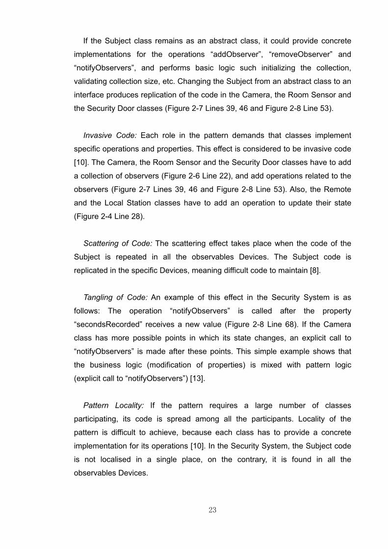
If the Subject class remains as an abstract class, it could provide concrete
implementations for the operations “addObserver”, “removeObserver” and
“notifyObservers”, and performs basic logic such initializing the collection,
validating collection size, etc. Changing the Subject from an abstract class to an
interface produces replication of the code in the Camera, the Room Sensor and
the Security Door classes (Figure 2-7 Lines 39, 46 and Figure 2-8 Line 53).
Invasive Code: Each role in the pattern demands that classes implement
specific operations and properties. This effect is considered to be invasive code
[10]. The Camera, the Room Sensor and the Security Door classes have to add
a collection of observers (Figure 2-6 Line 22), and add operations related to the
observers (Figure 2-7 Lines 39, 46 and Figure 2-8 Line 53). Also, the Remote
and the Local Station classes have to add an operation to update their state
(Figure 2-4 Line 28).
Scattering of Code: The scattering effect takes place when the code of the
Subject is repeated in all the observables Devices. The Subject code is
replicated in the specific Devices, meaning difficult code to maintain [8].
Tangling of Code: An example of this effect in the Security System is as
follows: The operation “notifyObservers” is called after the property
“secondsRecorded” receives a new value (Figure 2-8 Line 68). If the Camera
class has more possible points in which its state changes, an explicit call to
“notifyObservers” is made after these points. This simple example shows that
the business logic (modification of properties) is mixed with pattern logic
(explicit call to “notifyObservers”) [13].
Pattern Locality: If the pattern requires a large number of classes
participating, its code is spread among all the participants. Locality of the
pattern is difficult to achieve, because each class has to provide a concrete
implementation for its operations [10]. In the Security System, the Subject code
is not localised in a single place, on the contrary, it is found in all the
observables Devices.
24
Improvements to OOP and patterns are being developed with the help of
other techniques and technologies [14]. The next section gives an overview of
an approach to solve these issues.
2.5 Aspect Oriented Programming
Aspect Oriented Programming (AOP) is a programming paradigm that
emerged at the end of the 1990s as a complement to OOP [15]. AOP was
created as a result of different initiatives to manage separation of concerns [16].
Basically, it allows software developers to work with cross-cutting concerns in
separate units of processing to improve maintenance and reusability [17].
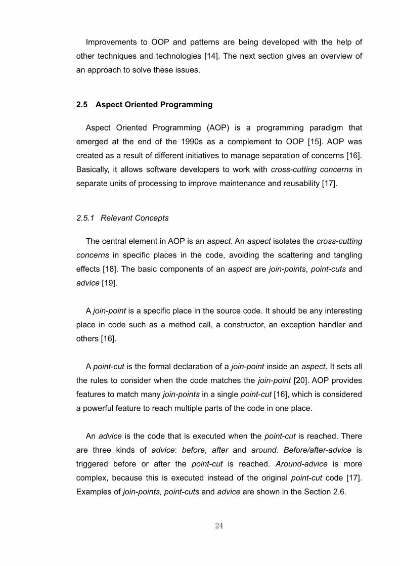
2.5.1 Relevant Concepts
The central element in AOP is an aspect. An aspect isolates the cross-cutting
concerns in specific places in the code, avoiding the scattering and tangling
effects [18]. The basic components of an aspect are join-points, point-cuts and
advice [19].
A join-point is a specific place in the source code. It should be any interesting
place in code such as a method call, a constructor, an exception handler and
others [16].
A point-cut is the formal declaration of a join-point inside an aspect. It sets all
the rules to consider when the code matches the join-point [20]. AOP provides
features to match many join-points in a single point-cut [16], which is considered
a powerful feature to reach multiple parts of the code in one place.
An advice is the code that is executed when the point-cut is reached. There
are three kinds of advice: before, after and around. Before/after-advice is
triggered before or after the point-cut is reached. Around-advice is more
complex, because this is executed instead of the original point-cut code [17].
Examples of join-points, point-cuts and advice are shown in the Section 2.6.
25
AOP offers a new approach to managing cross-cutting concerns. It is
considered a promising technology to solve problems in many areas of software
engineering such as design, architecture [21], development and testing [22].
Researchers are working in a variety of topics in order to improve AOP as a
technology [23] [24], and create new areas of research with it [25] [26]. This
paradigm has been used in a wide range of projects with a variety of results in
the industry and the academia [9].
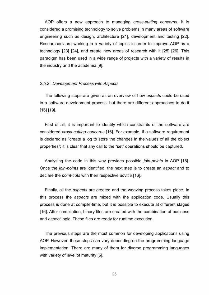
2.5.2 Development Process with Aspects
The following steps are given as an overview of how aspects could be used
in a software development process, but there are different approaches to do it
[16] [19].
First of all, it is important to identify which constraints of the software are
considered cross-cutting concerns [16]. For example, if a software requirement
is declared as “create a log to store the changes in the values of all the object
properties”; it is clear that any call to the “set” operations should be captured.
Analysing the code in this way provides possible join-points in AOP [18].
Once the join-points are identified, the next step is to create an aspect and to
declare the point-cuts with their respective advice [16].
Finally, all the aspects are created and the weaving process takes place. In
this process the aspects are mixed with the application code. Usually this
process is done at compile-time, but it is possible to execute at different stages
[16]. After compilation, binary files are created with the combination of business
and aspect logic. These files are ready for runtime execution.
The previous steps are the most common for developing applications using
AOP. However, these steps can vary depending on the programming language
implementation. There are many of them for diverse programming languages
with variety of level of maturity [5].

26
2.6 A Simple Example with AOP
In order to explain the concepts of AOP, the Security System explained in the
previous sections is considered with an extra requirement useful to show a
simple use of AOP. Imagine that one of the requirements of the system is that
all the changes in the properties of a Room Sensor must be recorded in a log.
That log must contain the previous value and the new value of the property.
This requirement is an example of a cross-cutting concern. In order to solve it
with OOP, software developers add code inside every set operation of the
Room Sensor. That code takes the value before and after any modification of
the property, and then records that information in a log (Figure 2-9 Lines 92,
98). If a Room Sensor has a large number of properties, that code is replicated
among all the “set” operations. This is one of many approaches to satisfy this
requirement, maybe it is not the most suitable way to do it but it is useful to
illustrate the potential problems.
Figure 2-9. An OOP approach to solve the logging operations of a Room Sensor.
2.6.1 Code Implementation
In order to show the approach using aspects, the example has been
developed using AspectJ, which is one of the implementations of AOP for Java
[16]. Relevant information about AspectJ is given in the Section 3, but the
purpose of this example is to show how is possible to solve the logging
requirement with AOP. The structure of the aspect created is as follows:

27
The aspect is declared and called Logging Operation with the keyword
aspect (Figure 2-10 Line 8). An aspect looks similar to a Java class, but
contains an extra set of keywords specifically for AOP manipulation.
A point-cut called “personDetectedChanges” is declared (Figure 2-10 Line
13). It specifies that the join-point of interest is the execution of the operation
“setPersonsDetected” of the Room Sensor class (Figure 2-10 Line 14). In
addition to that, a before-advice (Figure 2-10 Line 20) and an after-advice
(Figure 2-10 Line 28) are declared, each of them with a simple code to be
executed when the point-cut is reached.
Figure 2-10. Aspect implementing the logging requirement for the Room Sensor.
2.6.2 Simple Scenario Analysis
The Security System is compiled using the AspectJ compiler. This means
that the code of the aspect is mixed with the Java source code. The application
is executed as follows: First of all, a new Room Sensor is created (Figure 2-11
Line 102). After that, the application changes the value of the property
“personsDetected” using the operation “setPersonsDetected” with a value of 10
(Figure 2-11 Line 106). That specific line of code matches with the point-cut
declaration (Figure 2-10 Line 14).

28
The aspect calls the before-advice (Figure 2-10 Line 20), and prints on the
console the value of the property “personsDetected”. At this moment the value
is 0. Once the advice is finished, the operation “setPersonsDetected” is
executed.
Once this operation is finished, the after-advice of the aspect is executed
(Figure 2-10 Line 28) and prints on the console the property “personsDetected”
after the modification. At this moment, the value is 10 because the modification
was carried out. After that, the application continues changing the values and
the appropriate outputs are printed on the console (Figure 2-12 Lines 1 to 6).
Figure 2-11. The Security System modifying a Room Sensor.
Figure 2-12. Output generated by the Aspect in the advice implementations.
Using AOP, the cross-cutting concern (logging requirement) was solved
without modifying the code of Room Sensor class (in contrast to the OOP
approach). All the logic related to the logging operation is localised in the
aspect. If it is necessary to create a log for more properties, it should be
declared in the aspect adding more point-cuts and advice if necessary.

29
This simple example shows an AOP approach to solve the logging issue. An
AOP implementation for the issues identified in the Observer pattern is
developed in the Chapter 4.
2.7 The Aspect Oriented Paradigm and Software Development
This section presents a summary of relevant research in the area of AOP and
design patterns. It presents how AOP is changing the way in which software
development is carried out, and how it could modify the implementation of
design patterns.
2.7.1 AOP and Software Development Process
AOP has been applied in a variety of projects by the software engineering
community, and has reached a significant level of maturity [9]. The influence of
aspects in diverse areas of software development is increasing [27] [28] and is
shown as follows.
2.7.2 Development
Some studies present how AOP promotes new approaches to developing
software applications [21] [29]. Those approaches require adding extra steps in
the software development process to identify requirements with cross-cutting
concerns [19]. It is important to design a suitable implementation with AOP to
meet those requirements, using point-cuts and advice properly [30].
Other research discusses how aspects could impact software component
development. That research claims that AOP is a suitable technique to improve
the adaptability of third-party software components. Moreover, it allows
developers to extend and modify software components without modifying the
source code [28].
30
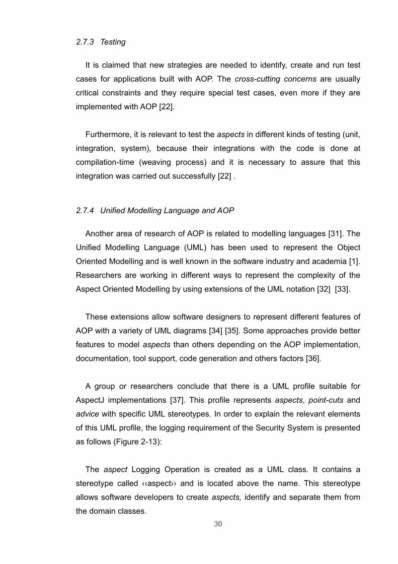
2.7.3 Testing
It is claimed that new strategies are needed to identify, create and run test
cases for applications built with AOP. The cross-cutting concerns are usually
critical constraints and they require special test cases, even more if they are
implemented with AOP [22].
Furthermore, it is relevant to test the aspects in different kinds of testing (unit,
integration, system), because their integrations with the code is done at
compilation-time (weaving process) and it is necessary to assure that this
integration was carried out successfully [22] .
2.7.4 Unified Modelling Language and AOP
Another area of research of AOP is related to modelling languages [31]. The
Unified Modelling Language (UML) has been used to represent the Object
Oriented Modelling and is well known in the software industry and academia [1].
Researchers are working in different ways to represent the complexity of the
Aspect Oriented Modelling by using extensions of the UML notation [32] [33].
These extensions allow software designers to represent different features of
AOP with a variety of UML diagrams [34] [35]. Some approaches provide better
features to model aspects than others depending on the AOP implementation,
documentation, tool support, code generation and others factors [36].
A group or researchers conclude that there is a UML profile suitable for
AspectJ implementations [37]. This profile represents aspects, point-cuts and
advice with specific UML stereotypes. In order to explain the relevant elements
of this UML profile, the logging requirement of the Security System is presented
as follows (Figure 2-13):
The aspect Logging Operation is created as a UML class. It contains a
stereotype called ‹‹aspect›› and is located above the name. This stereotype
allows software developers to create aspects, identify and separate them from
the domain classes.

31
All the advice and point-cuts are represented as operations with additional
stereotypes in each case. The point-cut “personDetectedChanges” contains the
stereotype ‹‹pointcut›› before its name.
Figure 2-13. Aspect UML representing the Logging requirement.
In a similar way, both advice declarations have the stereotype ‹‹advice››
before their names. Additionally they have the appropriate modifiers that
indicate if they are executed before or after the point-cut is reached. A
relationship with the class Room Sensor is represented as a UML association
with a stereotype called ‹‹crosscut››. It means that the aspect uses that class
and contains the cross-cutting concerns that are related to the class Room
Sensor.
2.7.5 Design Patterns
It is claimed that AOP solves the issues with design patterns discussed in the
previous example. Aspects remove the invasive code of the patterns and put it
in a centralised place [13], avoiding the scattering and tangling effects in the
code [10], and improving reusability and locality of patterns [14]. AOP allows
aspects to add properties, operations and even interfaces to classes without
modifying their source code [3]. As a result, the issue of multiple inheritance in
pattern code is solved [12].
However, researchers have pointed out possible issues and improvements
for AOP [38]. In some cases, the aspect code causes unexpected effects in
complex patterns. It increases the number of classes participating in the
patterns (including aspects) and is difficult to understand them [39].

32
In general, this project investigates and analyses the trade-offs presented in
the OOP and AOP approaches. Based on the information presented in this
chapter, the next one gives details about the project, the main objectives and
methodology applied.
33
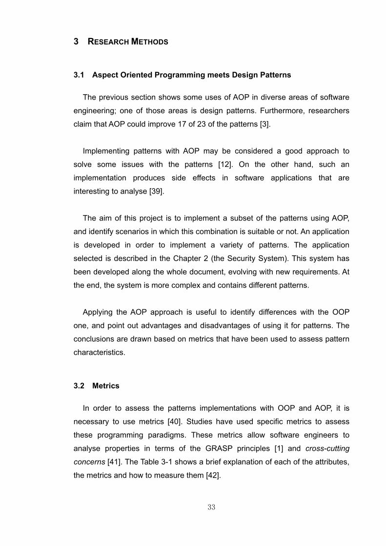
3 RESEARCH METHODS
3.1 Aspect Oriented Programming meets Design Patterns
The previous section shows some uses of AOP in diverse areas of software
engineering; one of those areas is design patterns. Furthermore, researchers
claim that AOP could improve 17 of 23 of the patterns [3].
Implementing patterns with AOP may be considered a good approach to
solve some issues with the patterns [12]. On the other hand, such an
implementation produces side effects in software applications that are
interesting to analyse [39].
The aim of this project is to implement a subset of the patterns using AOP,
and identify scenarios in which this combination is suitable or not. An application
is developed in order to implement a variety of patterns. The application
selected is described in the Chapter 2 (the Security System). This system has
been developed along the whole document, evolving with new requirements. At
the end, the system is more complex and contains different patterns.
Applying the AOP approach is useful to identify differences with the OOP
one, and point out advantages and disadvantages of using it for patterns. The
conclusions are drawn based on metrics that have been used to assess pattern
characteristics.
3.2 Metrics
In order to assess the patterns implementations with OOP and AOP, it is
necessary to use metrics [40]. Studies have used specific metrics to assess
these programming paradigms. These metrics allow software engineers to
analyse properties in terms of the GRASP principles [1] and cross-cutting
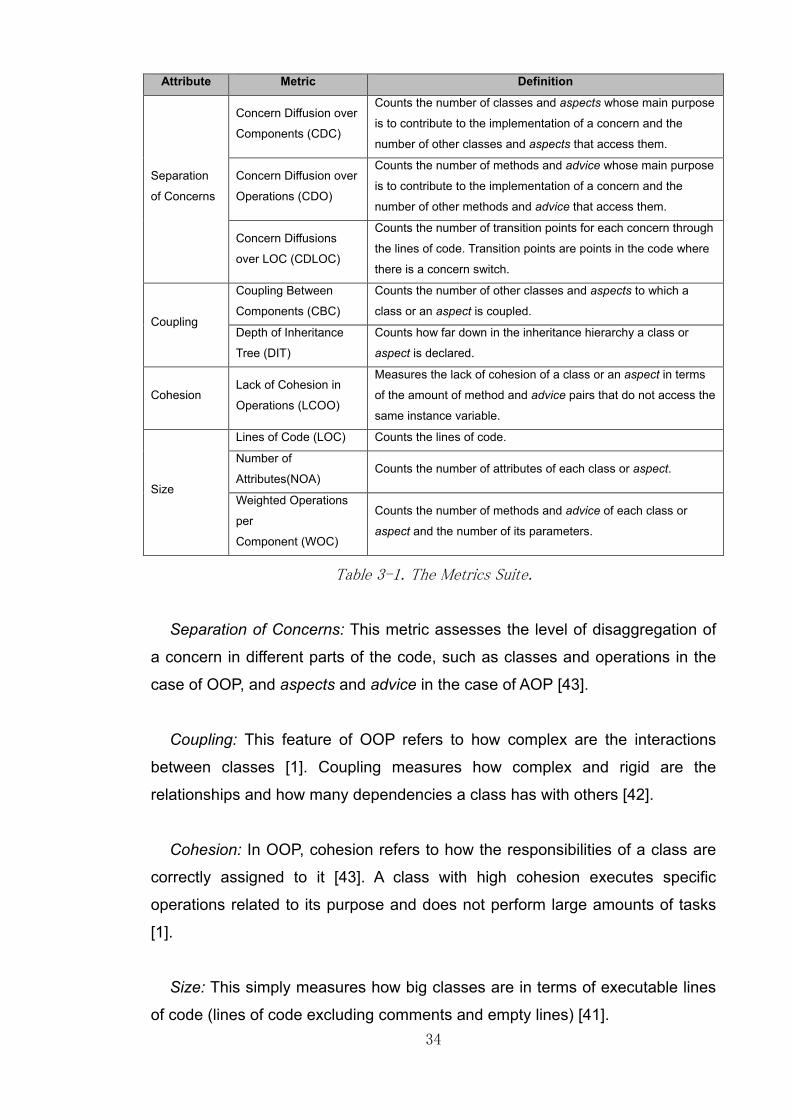
concerns [41]. The Table 3-1 shows a brief explanation of each of the attributes,
the metrics and how to measure them [42].
34
Attribute Metric Definition
Separation
of Concerns
Concern Diffusion over
Components (CDC)
Counts the number of classes and aspects whose main purpose
is to contribute to the implementation of a concern and the
number of other classes and aspects that access them.
Concern Diffusion over
Operations (CDO)
Counts the number of methods and advice whose main purpose
is to contribute to the implementation of a concern and the
number of other methods and advice that access them.
Concern Diffusions
over LOC (CDLOC)
Counts the number of transition points for each concern through
the lines of code. Transition points are points in the code where
there is a concern switch.
Coupling
Coupling Between
Components (CBC)
Counts the number of other classes and aspects to which a
class or an aspect is coupled.
Depth of Inheritance
Tree (DIT)
Counts how far down in the inheritance hierarchy a class or
aspect is declared.
Cohesion Lack of Cohesion in
Operations (LCOO)
Measures the lack of cohesion of a class or an aspect in terms
of the amount of method and advice pairs that do not access the
same instance variable.
Size
Lines of Code (LOC) Counts the lines of code.
Number of
Attributes(NOA) Counts the number of attributes of each class or aspect.
Weighted Operations
per
Component (WOC)
Counts the number of methods and advice of each class or
aspect and the number of its parameters.
Table 3-1. The Metrics Suite.
Separation of Concerns: This metric assesses the level of disaggregation of
a concern in different parts of the code, such as classes and operations in the
case of OOP, and aspects and advice in the case of AOP [43].
Coupling: This feature of OOP refers to how complex are the interactions
between classes [1]. Coupling measures how complex and rigid are the
relationships and how many dependencies a class has with others [42].
Cohesion: In OOP, cohesion refers to how the responsibilities of a class are
correctly assigned to it [43]. A class with high cohesion executes specific
operations related to its purpose and does not perform large amounts of tasks
[1].
Size: This simply measures how big classes are in terms of executable lines
of code (lines of code excluding comments and empty lines) [41].

35
3.3 Aspect J (Aspect Implementation for Java)
AspectJ is one of the most popular implementations of AOP for Java [16]. It
has been developed by XPARC (Xerox Palo Alto Research Centre) and the
main researcher on AOP called Gregor Kiczales.
Recent research concluded that AspectJ is one of the most mature
implementations of AOP. It continuously presents improvements in terms of
documentation, stability, integration with tools and core language features [5].
Based on these facts, the project is being developed with AspectJ.
Furthermore, AspectJ is considered as an implementation with scalability
properties. This feature allows software engineers to use it in large-scale
systems with good results. It helps to achieve a relevant reduction in scattered
code with a low performance overhead. These results support the maturity of
AspectJ as an implementation of AOP [44].
AspectJ works with the following procedure: Firstly, the Java code that
reflects the business logic of an application is developed. Secondly, the aspects
are developed in separate units (source code files) with elements such as point-
cuts, marker interfaces and advice.
Once all the business logic and aspects are developed, the next step is the
weaving process. This is done by the AspectJ compiler, which compiles Java
source code, identifies in it the point-cuts and mixes the aspect code with the
Java code [4]. Finally, the compiler produces Java runtime files that contain the
business logic and the aspect logic combined [19].
There are implementations of AspectJ for most of the Integrated
Development Environments (IDEs). Those implementations provide tools to
help developers to work properly with AOP and Java code. The advantage of
using IDEs is that they offer features such as debugging and cross-references
between the Java code and aspect code [45].The applications for this project
are developed using Eclipse Indigo IDE 3.7, the AspectJ Development Tools for
Eclipse 2.2, AspectJ 1.7.0 and the Java Development Kit version 1.6.0.
36
3.4 Project Methodology
The project has been developed following some of the best practices of
iterative development. It involves a series of iterations in which a set of activities
are carried out in order to develop different stages of the project. Those
iterations are time-boxed and the results of each iteration is executable and
tested code for the system [1].
A single iteration contains an exploration of patterns, implementing a subset
of the patterns with OOP and AOP, measuring the metrics, analysing the results,
writing the conclusions and refining all the tasks before the next iteration. This
approach allows the Security System (discussed in Chapter 2) to be developed
incrementally with high adaptability to change [1]. The tasks performed per
iteration are as follows and are explained in detail:
3.4.1 Explore a subset of the patterns to apply.
The project selects iteratively a subset of the 23 well known design patterns
[2]. Small software modules for the Security System are developed applying the
patterns. The patterns are chosen based on a suitable scenario for the Security
System and for being promising to improve by using AOP.
3.4.2 Develop an application using OOP and AOP.
In order to develop the Security System and analyse its behaviour, the
implementation is divided in two approaches: OOP and AOP. The first stage is
to code the application using OOP. In this approach the patterns are applied as
usual based on the guidelines for each pattern [2]. After that, the second stage
is the implementation of the pattern using AOP. All the code presented in this
document has been developed by the author of this project, except for the
aspect library that has been developed by Gregor Kiczales and Jan
Hannemann [3].
37
3.4.3 Assess and review the metrics.
Once the Security System is running and basic tests of functionalities are
done, the next step is assessing both approaches with the metrics. The values
of the metrics show differences between OOP and AOP approaches, in that way
some conclusions are drawn to identify improvements and drawbacks in the
patterns selected.
3.4.4 Identify advantages and disadvantages of AOP.
This analysis examines possible situations in which patterns with AOP are
suitable or not in comparison with the conventional OOP implementations.
These conclusions support or otherwise the results of research that claims
improvements in patterns using AOP [3].
3.4.5 Document the results.
Finally, the results are summarised and written. All the conclusions are
gathered in order to identify useful information for the next iteration. The
organisation of the results before the next iteration is important. It is useful to
prepare the next set of patterns, and to refine the previous application with more
patterns.
The next chapters go through different patterns selected for the Security
System. They are grouped in order to associate similar business scenarios,
identify pattern interactions and draw some conclusions in terms of the analysis
of the metrics.

38
4 THE OBSERVER PATTERN
This chapter contains the AOP implementation of the Observer pattern.
Additionally, it presents the metrics analysed for both approaches (OOP and
AOP) and draws the first set of conclusions of the pattern implementation by
using AOP.
4.1 Business Scenario
The description of the application selected (the Security System) to apply the
Observer pattern is given in the Chapter 2 (Section 2.4) as well as the business
scenario that motivates this pattern with OOP. That implementation is based on
the guidelines presented in the design pattern catalogue [2].
4.2 AOP Implementation
The AOP approach is based on the guidelines and examples provided by the
aspect library [3]. This approach changes the pattern structure and the code
implementation. First of all, Subject and Observer classes are not needed;
instead of them an abstract aspect called Observer Protocol is declared.
This aspect contains nearly all the code implementation of the pattern. The
class diagram with the AOP implementation using an appropriate UML notation
[37] (see Chapter 2 - Section 2.7.4 for details) is shown in the Figure 4-1.
The aspect declares two marker interfaces related to the pattern roles:
Subject and Observer. A point-cut called “subjectChange” is declared as
abstract in order to be specified by the concrete aspects [3].
An after-advice is declared in order to execute the logic of the operation
“notifyObservers”. It takes the Subject, gets its list of observers, and calls the
operation “update” for each of them. The aspect contains the operations
“addObserver” and “removeObserver”. The operation “update” is declared as
abstract in order to be specified in the concrete aspects [3].

39
Figure 4-1. Observer pattern for the Security System using AOP.
Figure 4-2. Remote Station Aspect for the Security System.

40
Two concrete aspects are declared in order to represent pattern instances
(Remote Station Observer Aspect and Local Station Observer Aspect). They
have a hierarchical relationship with the abstract Observer Protocol (Figure 4-2
Line 15). The operation “update” is implemented with concrete code (Figure 4-2
Line 37).
The application of the roles Subject and Observer is carried out in the aspect
by using the declare parents keyword (Figure 4-2 Lines 19 to 22). This feature
allows aspects to add new properties, methods and hierarchical relationships to
a class without modifying its actual source code [13].
The Remote and Local stations act as Observers and the Devices act as
Subjects. Applying the roles in the aspects is how AOP solves the issue of
multiple inheritance in Java. AOP declares in the aspects new hierarchical
relationships without modifying the source code of the classes involved [3].
The point-cut called “subjectChange” is implemented to match any call to the
operations “setSecondsRecorded” of the Camera class, “setPersonsDetected”
of the Room Sensor class and “setLockLevel” of the Security Door (Figure 4-2
Lines 28,29 and 30). This point-cut shows the AOP approach to solve the
scattering and tangling effects [12].
The aspect declares in this point-cut all the possible places where the
Subjects can change their state. There is no need to replicate and mix the
business code with an explicit call to the operation “notifyObservers” [3].
However, this approach implies that the aspect is coupled with three classes
from the domain in just one instruction.
Basically, all the logic of the Observer pattern remains similar, but the
structure of the pattern with AOP is different. Most of the pattern code is
localised in the abstract aspect Observer Protocol, and specific pieces of code
are implemented in the concrete aspects [3].

41
4.3 Metrics
The metrics suite discussed in the Chapter 3, has been developed by a large
group of researchers in order to analyse the object oriented paradigm [46]. This
set of metrics has been applied in different approaches of OOP and AOP [39]
[40] [41] in order to understand their implications in design and code
implementations.
These metrics are important to understand the cross-cutting concerns and
their behaviour in the software development [43] [42]. The metrics used in the
Security System have been applied following the next guidelines (Table 4-1):
Attribute Metric Criteria / Approach
OOP AOP
Separation
of
Concerns
Concern
Diffusion
over
Components
(CDC)
Take into account the classes that
contain pattern code (For example
pattern classes such as Observer
and Subject, and domain classes
such as Camera and Room
Sensor).
Additionally include the most
relevant client classes (classes
that interact directly with the
pattern classes).
Take into account just the classes and
aspects that contain pattern code. If a
class participates in the pattern but
does not have any pattern code, it is
not included.
This is because that class is
participating in the pattern but indirectly
through the aspect. For example the
Camera and the Room Sensors are
participating in the pattern but do not
contain any pattern code at all. All the
pattern code is in the aspects, for that
reason those classes are not
considered into this approach.
Additionally include the most relevant
client classes.
Concern
Diffusion
over
Operations
(CDO)
Take into account the operations
of the classes included in the
previous metric.
Take into account the
operations/advice of the
classes/aspects included in the
previous metric.
Concern
Diffusions
over LOC
(CDLOC)
Take into account all the switch
points and multiply them by two. A
switch point is the place where the
code changes from a line of code
with business logic to a line of
Take into account the same rules for
the OOP, but this metric does not
include any aspects because each of
them are developed to contain the
pattern code (cross-cutting concern)

42
Attribute Metric Criteria / Approach
OOP AOP
code with cross-cutting concern.
For example, in the Observer
pattern a switch point is located
before and after the
“notifyObservers” operation is
called.
The organisation of the code
could affect this metric, so it is
assumed that the appearance of
the pattern code is not organised
(worst-case). For more details
review [43] [42]
and is not mixed with the business
logic. In that way there are no switch
points in the aspects.
Coupling
Coupling
Between
Components
(CBC)
For each class and aspect that is participating in the pattern (directly and
indirectly), take into account all the listed components in the import
statement plus the components in the same package that interact with each
of them.
Depth of
Inheritance
Tree (DIT)
Take into account the pattern classes and aspect that have any kind of
hierarchical relationships in order to fulfil the pattern structure. The
hierarchical relationships included in this metric are part of the domain
analysis and part of the pattern code.
Cohesion
Lack of
Cohesion in
Operations
(LCOO)
Take the total amount of operations and the total amount of properties of
each class or aspect that is participating in the pattern (directly and
indirectly). Classes and aspects without any attribute are not considered in
this metric. Then apply the formula and guidelines for this metric [43] [47].
Size
Lines of
Code (LOC)
Count the lines of code of the classes that are participating in the pattern
(directly and indirectly) and add them to calculate the total amount of lines of
code involved in the pattern.
Number of
Attributes
(NOA)
Count the number of properties of the classes that are participating in the
pattern (directly and indirectly) and add them to calculate the total amount of
properties involved in the pattern.
Weighted
Operations
per
Component
(WOC)
Count the number of parameters listed in the signature of the operations that
are participating in the pattern. Then identify the amount of operations from 0
to N levels of complexity depending on the number of the N parameters.
Table 4-1. Assessment guidelines for the metrics suite.

43
The metric values and their formulas are recorded to keep track of all the
classes and aspects involved. These records are in a spreadsheet that helps to
calculate the metrics values easily. Information about classes, aspects,
properties, operations and point-cuts are the main source for the metrics.
This data is collected directly from the source code and put into special
information cells in the spreadsheet. For example, a class name with its list of
properties and operations, or an aspect with its advice and point-cuts are put in
the information cells. The spreadsheet contains specific formulas to calculate
the metrics based on the information provided in the information cells. Most of
the metrics are shown in each chapter, but the DIT and CBC metrics are shown
in detail in Appendix A.
4.4 Metrics Analysis
The different attributes of the metrics for the Observer pattern are discussed
as follows (Table 4-2):
Metric Observer
OOP AOP
Concern Diffusion over Components (CDC) 12 7
Concern Diffusion over Operations (CDO) 22 11
Concern Diffusions over LOC (CDLOC) 72 40
Coupling Between Components (CBC) 65 84
Lines of Code (LOC) 663 740
Number of Attributes (NOA) 17 14
Weighted Operations per Component (WOC)
0 Parameters 34 29
1 Parameters 26 13
2 Parameters 4 9
3 Parameters 3 3
Table 4-2. Metrics results for the Observer patterns.
Separation of Concerns: In general terms, the metric values show that the
AOP implementation provides an improvement of the separation of concerns for
the Observer pattern. The OOP contains 12 classes related to the pattern; on
the other hand the AOP contains 7 classes including aspects (CDC metrics).

44
AOP reduces the number of classes because a large amount of the pattern
code is localised in the Observer Protocol avoiding replication and increasing
reusability of the pattern [13].
In terms of the operations participating in the pattern (CDO metric), the OOP
approach gives 22 operations and the AOP one contains 11 operations and
advice. The number is higher with OOP because the operations defined in the
Subject class have to be replicated in the Devices due to the multiple
inheritance issue.
The AOP implementation has a reduction because the abstract aspect
implements most of the code of the Subject and the Observer classes in the
Observer Protocol [3]. Additionally the aspect manages the multiple inheritance
in a different way that helps to reduce the replication of code.
In terms of the tangling and scattering effects, the CDLOC metric shows that
the OOP approach contains 72 switch points in contrast to the 40 provided by
the AOP implementation. These values show how the cross-cutting concern
(pattern code) is mixed with the business code. AOP reduces that effect nearly
by 44% because most of the pattern code is developed in the aspect rather than
in the participating classes.
However, this effect is still present in the AOP approach, because other
classes require the aspects to interact with pattern operations such as
“addObserver” or “removeObserver” (discussed later in the Chapter 8). That is
why the cross-cutting concern is not removed completely.
Coupling: In terms of hierarchical relationships, the AOP approach reduces
the size of the inheritance tree (DIT metric) by one level for all the pattern
classes. The hierarchical relationships are applied in the aspect rather than
directly in the code. This means that the domain classes could have a direct
hierarchical relationship (extending rather than implementing) [13].

45
The domain classes Camera, Room Sensor and Security Door do not have
the Subject hierarchical relationships, and the Remote and Local stations do not
have the relationships with the Observer class. These relationships are applied
in the pattern without imposing any additional restriction to the class in the
source code (Table A-7).
The number of dependencies (CBC metric) in the classes with the OOP
approach is lower than the AOP one. In the OOP scenario, the dependencies
with the Subject and the Observer classes are replicated in all the different
pattern classes. On the other hand, in the AOP implementation these
relationships are implemented once in the aspect, but it is still coupled with
other pattern classes, increasing the number of its dependencies [39].
Cohesion: The AOP implementation increases slightly the cohesion in most
of the participating classes (LCOO metric). A low value in this metric means
better cohesion. By using AOP, all the domain classes are more cohesive
because the attributes and operations added by the pattern are managed in the
aspects.
However, this improvement is not significant in terms of the metric value.
Additionally, the aspect Observer Protocol is a component with low cohesion,
because it contains a small amount of attributes and a large number of
operations/advice, and that behaviour scores low in this metric (Table A-8).
Size: The number of lines of code of classes participating in the pattern (LOC
metric) increases with the AOP implementation in comparison to the OOP one.
It means that even thought the scattering and tangling effects are reduced in
this particular scenario, this approach adds aspects (more classes) into the
code in order to perform the cross-cutting concern code [39].
The number of attributes (NOA metric) involved in the pattern is slightly
reduced in the AOP approach in comparison with the OOP one. In this scenario,
the list of observers is replicated in the OOP approach per class that plays the
Subject role.

46
By using AOP, the list is controlled once by the Observer Protocol and it is
not necessary to replicate it [3]. Additionally the concrete aspects do not have
attributes.
The WOC metric assumes that the operations are more complex based on
their number of the parameters. AOP reduces the amount of operations
involved in the pattern code, but it does not help to reduce the complexity of
them. There is no significant difference between both approaches with this
metric of complexity.
4.5 Conclusions
AOP provides a different approach to the implementation of the Observer
pattern. It takes the pattern code and put it into the aspects. One of the
advantages of this is the reduction of the inheritance tree in the pattern classes,
because all the hierarchical relationships of the pattern are implemented in the
aspect rather than directly implemented in the domain classes [3]. This feature
allows software developers to use the single inheritance relationships for
domain classes rather than pattern constraints.
Another advantage is the localisation of the pattern code in the aspects,
avoiding the tangling and scattering effects. Any possible modifications in the
pattern logic (for example adding new possible points of change for the Subject
classes or changing the rules for adding or removing observers) are easier to
implement with AOP. These changes are localised in the aspects and are not
mixed with the business code, creating a code cleaner in terms of these effects
[12].
On the other hand, some features about coupling and size are not good
enough in comparison to the OOP implementation. There are no significant
differences in these features by using AOP. In fact, the number of lines of code
increases with the AOP implementation, meaning that the code is larger in size
with more classes (or aspects) participating in the pattern [39].
47
One of the drawbacks of the AOP approach is the code complexity. The
pattern logic contained in the aspect is not easy to understand and requires a
good understanding of the features of AOP as well as a good level of
abstraction of the pattern itself. In addition to that, the tangling and scattering
effects are not removed at all with AOP. This approach created new complex
dependencies in other classes that use the pattern, meaning that the code is
more coupled and difficult to maintain.
However, it is possible to have different approaches of this pattern by using
AOP. If the structure of the domain classes changes slightly to avoid the
multiple inheritance issue, the hierarchical relationships between classes are
not an obstacle for the Observer pattern. In this scenario, the notification issue
is the only concern managed by the aspects. This change could make the
aspect cleaner and could improve its cohesion. Multiples way of developing
patterns by using AOP should be explored to avoid the side effects discussed in
this section.

48
5 THE COMPOSITE, ADAPTER AND PROXY PATTERNS
In order to introduce the Composite, Adapter and Proxy patterns and their
implementations with both programming approaches, it is necessary to set the
business scenarios that motivate the implementations of these patterns. These
patterns are related in terms of their business rules and their group of
participating classes. These are as follows:
5.1 Business Scenarios
The Security System requires managing groups of devices. This feature is
useful because a group of devices can be located in different places of the
building, such as Cameras with Room Sensors, or Laptops with Printers.
A group of devices can be created with different levels of composition; it
means that it is possible to create a group with all the Printers in a room, all the
Cameras in a floor or any other combination of devices. This kind of
composition of devices allows the Security System to review the electrical
safety check per group of devices and single devices. The Monitoring Stations
have the responsibility of generating a report with the Devices that require a
safety check for the next week.
If a Device requires an electrical safety check, the Monitoring Station reports
the issue and some actions are taken into consideration, such as replace the
Device or avoid using the room for health and safety rules. In the case of a
group of devices, if any of its Devices require the safety check, the Monitoring
Station might report the whole group to be checked.
The safety check report can be generated every time that the Monitoring
Stations are initialized. In that way it is possible to have information about the
Devices earlier because the stations are initialized early in the morning. The
system can use different third-party classes to generate reports in different
format such as TXT, CSV and XML formats.

49
The system should be ready to use other third-party classes for other formats
of reports such as Spreadsheets or Table Documents. In that way, the
interactions between the Monitoring Stations and the report classes should be
flexible and prepare the code for future changes.
The Monitoring Station uses two basic operations to generate the report: Set
the folder where the report is stored, and create the report by providing the list
of Devices that require the safety check. Each third-party class has specific
properties and operations to create the report, so the issue is trying to unify all
the different interfaces to generate the report with the two basic operations.
Additionally, there are new conditions in terms of Monitoring Stations. The
Security System has a set of Monitoring Stations. There are two types of
stations: Remote and Local Stations. Local Stations are located in the same
building facilities and the Remote Stations are located far away from it.
The system requires managing both stations equally in terms of common
operations. This means that the system does not need to know all the details of
localisation of the Remote Stations. The behaviour of the Remote Stations
should be the same as the Local ones without any concerns about
communication, localisation, performance, etc.
5.2 The Composite Pattern
5.2.1 OOP Approach
The Composite pattern represents one of the best practices to create and
manipulate a tree-like structure. Basically, this pattern is comprised of three
classes, one represents an abstract component, another represents a single
component or “leaf” in the tree-structure, and finally another represents the
composite component [2].

50
In the Security System, the OOP approach to this pattern is described as
follows: The Device class is the abstract component and contains the definitions
of all its operations. For example, it provides the business operations called
“safetyCheck” and “getDescription” that should be implemented for both single
and composite components.
Figure 5-1. Composite pattern for the Security System using OOP.
A single component or “leaf” is represented by the Single Device class. This
class is abstract due to the fact that there are different kinds of devices such as
IT and Security Devices, and all of them share similar properties and
operations. A composite component is represented by the Device Group class.
This class has an aggregation relationship with the abstract Device class to
represent the tree-like structure. The two relationships between Device Group
and Device classes are the key feature of the pattern to achieve flexibility with
different levels of composition [2] (Figure 5-1).
The “safetyCheck” operation is implemented in both classes Single Device
and Device Group. In the Single Device implementation, the code validates the
business rules of a safety check (weekly/annual review).

51
In the case of Device Group, the implementation of this operation traverses
the tree-like structure and asks each element of the group for the safety check
validation, treating each of them as an abstract Device. If the element is a
Single Device, the appropriate business logic is executed, but if the element is a
Device Group, the traversal algorithm is executed again until all the Single
Devices or “leaves” are reached [7].
The Monitoring Station has a collection of Devices. For each of them, the
station calls the “safetyCheck” operation, and stores the Devices that require a
check in order to generate the appropriate report. The creation of reports is
discussed later on with another pattern. At this point, the important thing is to
point out that the Monitoring Stations in a specific moment calls the operation
“safetyCheck” for each of its Devices and the tree-like structure is traversed.
5.2.2 AOP Approach
The AOP implementation of the Composite pattern is presented as follows:
The aspect library has an abstract aspect called Composite Protocol that
contains all the reusable code of the pattern [3]. This aspect identifies the three
roles played in the pattern, Component, Leaf and Composite components and
declares them as marker interfaces (Figure 5-2).
Additionally, this aspect contains a hash-map that represents the aggregation
relationship between the Composite component and the abstract Component. In
that hash-map for each Composite a list of Components is stored [3].
In order to instantiate the Composite pattern, a concrete aspect called
Composite Devices Aspect is created. This aspect extends the Composite
Protocol and applies the roles of Component, Leaf and Composite components
to Device, Single Device and Device Group respectively. Additionally, the
generalisation relationships between Device and Single Device and between
Device and Device Group are set in the aspect.

52
Figure 5-2. Composite pattern for the Security System using AOP.
The aspect provides concrete implementations for the operation
“safetyCheck” for both roles Leaf and Composite. In the case of a Leaf
component, the implementation is basically the same business logic
implemented in the Single Device with OOP. For a Composite component, the
aspect uses the functions provided in the Composite Protocol for getting the
hash-map and the list, going through the list of Components and calling the
specific operations for each of them.
In this implementation the traversing algorithm is not the same as the OOP
approach due to the fact that the Composite Protocol uses a different tree-like
structure. It implements the relationships between the Composite and abstract
Component with a hash-map and a list [3]. In order to traverse the composite
structure, the Composite element gets from the hash-map the list of its children.

53
It is possible to have Single Devices or another Device Group as children.
Once the list is retrieved, the iteration process is carried out per each
component until all the Devices in the structure are reached. Basically, the
aspect uses an indirection (hash-map) in order to decouple the relationships
between a Composite component and its children.
5.3 The Adapter Pattern
5.3.1 OOP Approach
The Adapter pattern is the appropriate approach to solve the flexibility issue
related to the creation of reports and future changes to include other formats.
The Adapter pattern solves the problem of managing different interfaces and
allows the system to work with a common interface to interact with classes that
have different interfaces [2].
Figure 5-3. Adapter pattern for the Security System using OOP.
In the Security System, the Monitoring Stations are responsible for
generating the safety check report. A Report Handler interface is created with
the definition of the two basic operations to create a report such as
“setOutputPath” and “createReport”.

54
Three concrete adapters are created to handle the different kinds of reports
[7]. XML Report Adapter, CSV Report Adapter and TXT Report Adapter. The
third-party classes are XML Report, CSV Report and TXT Report (Figure 5-3).
Each third-party class provides different number of operations to create the
report in the appropriate format. The corresponding Report Adapter has the
responsibility to manage the different operations within the two basic operations
provided by the interface. In that way, the Monitoring Stations call the
“setOutputPath” and “createReport” operations of the adapter independently of
the concrete third-party class. If in the future more third-party classes are added
to include more report formats, a concrete adapter should be created for each
of them [7].
For example, the XML Report provides the operations “setFilePath”,
“saveInfoToReport” and “saveXMLFile” to create a report. The Monitoring
Station calls the “setOutputPath” of the XML Report Adapter, which internally
instantiates the XML Report and calls the operation “setFilePath”. Then the
Monitoring Station provides the data to generate the report and calls the
operation “createReport” of the XML Report Adapter. It invokes internally two
operations, the first one called “saveInfoToReport” and then the operation
“saveXMLFile”, that actually flush the information into the physical file in the
folder.
5.3.2 AOP Approach
The AOP implementation of the Adapter is not structurally different from the
OOP one. Clearly the third-party classes remain the same because it is
suppose that they are not modified. The Report Handler interface remains the
same in order to provide the same two operations to generate a report. The
specific adapter classes are created, but they do not have any hierarchical
relationship with the interface and they do not have any concrete
implementation at all. These classes are empty because the whole pattern code
relies on the aspects [3] (Figure 5-4).

55
Figure 5-4. Adapter pattern for the Security System using AOP.
Three aspects are created to represent the pattern code called CSV Report
Adapter Aspect, XML Report Adapter Aspect and TXT Report Adapter Aspect. In
each aspect the hierarchical relationship between the adapter interface and the
concrete adapter is done through a declare-parents definition [3]. The concrete
implementations of the operations “setOutputPath” and “createReport” are in
the aspects.
Basically all the pattern code from the concrete adapter is moved into the
aspect. The only difference is that the AOP implementation does not apply
direct inheritance to the adapters, so it is possible to have another relationship
in them.
5.4 The Proxy Pattern
5.4.1 OOP Approach
The Proxy pattern is one of the best practices to control the access and
manipulation of a class through another or surrogate class [2]. The business
scenario requires the implementation of a Remote Proxy that is a local
representation of an object which is actually remote [7].

56
Figure 5-5. Proxy pattern for the Security System using OOP.
The Security System implements the Proxy pattern as follows: The Security
System class acts as a client that interacts with both Local and Remote
stations. The Monitoring Station is the common interface with the set of
operations for both stations. The Remote Station is the remote object for the
Security System. There is a Proxy Station that has a relationship with the
Remote Station and extends the Monitoring Station [2] (Figure 5-5).
The Security System is modified in order to do not have direct access to the
remote class. The only way to communicate with the Remote Station is through
the Proxy Station class. This proxy is in charge of all the issues about
communication, instantiation and localisation. At the same time, it deals with the
execution of the corresponding operations. The Proxy Station is a kind of
Monitoring Station, so the Security System calls the operations of the Proxy
Station class that are provided by the common interface, and this internally calls
the appropriate method of the actual Remote Station.
5.4.2 AOP Approach
The AOP implementation of the Proxy pattern is as follows: The aspect
library contains a Proxy Protocol [3]. This is an aspect with the common pattern
code. It provides a marker interface called Subject to be applied to the classes
that act as the common interface.

57
It declares an abstract point-cut called “requestByCaller” that must be
implemented in a concrete aspect to declare the specific points in the code to
be intercepted. The aspect provides an around-advice to be executed when the
point-cut is reached and executes the code to make the appropriate method
calling to the Remote Station (Figure 5-6).
Figure 5-6. Proxy pattern for the Security System using AOP.
A concrete aspect called Proxy Station Aspect is an instance of the Proxy
pattern. In this aspect the implementation of the Subject interface is applied to
the Monitoring Station. The Proxy Station class receives the hierarchical
relationships with the Monitoring Station.
The Proxy Station Aspect has a private property of type Remote Station, in
that way all the operations are handed over to this instance. The point-cut is
declared in order to intercept all the invocations for operations of the Monitoring
Station when the real object is a Proxy Station.
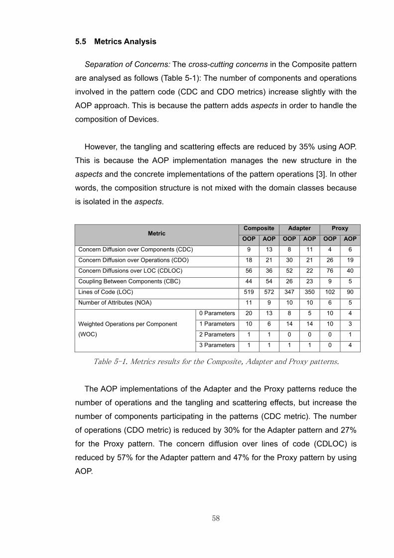
58
5.5 Metrics Analysis
Separation of Concerns: The cross-cutting concerns in the Composite pattern
are analysed as follows (Table 5-1): The number of components and operations
involved in the pattern code (CDC and CDO metrics) increase slightly with the
AOP approach. This is because the pattern adds aspects in order to handle the
composition of Devices.
However, the tangling and scattering effects are reduced by 35% using AOP.
This is because the AOP implementation manages the new structure in the
aspects and the concrete implementations of the pattern operations [3]. In other
words, the composition structure is not mixed with the domain classes because
is isolated in the aspects.
Metric Composite Adapter Proxy
OOP AOP OOP AOP OOP AOP
Concern Diffusion over Components (CDC) 9 13 8 11 4 6
Concern Diffusion over Operations (CDO) 18 21 30 21 26 19
Concern Diffusions over LOC (CDLOC) 56 36 52 22 76 40
Coupling Between Components (CBC) 44 54 26 23 9 5
Lines of Code (LOC) 519 572 347 350 102 90
Number of Attributes (NOA) 11 9 10 10 6 5
Weighted Operations per Component
(WOC)
0 Parameters 20 13 8 5 10 4
1 Parameters 10 6 14 14 10 3
2 Parameters 1 1 0 0 0 1
3 Parameters 1 1 1 1 0 4
Table 5-1. Metrics results for the Composite, Adapter and Proxy patterns.
The AOP implementations of the Adapter and the Proxy patterns reduce the
number of operations and the tangling and scattering effects, but increase the
number of components participating in the patterns (CDC metric). The number
of operations (CDO metric) is reduced by 30% for the Adapter pattern and 27%
for the Proxy pattern. The concern diffusion over lines of code (CDLOC) is
reduced by 57% for the Adapter pattern and 47% for the Proxy pattern by using
AOP.

59
For the Adapter pattern, this reduction is the result of moving the pattern
code into the aspects. However, the number of participating components in the
pattern increases (CDC metric) due to the fact that the AOP implementation
creates new aspects for each adapter [39].
In the case of the Proxy pattern, the complete interaction between the Proxy
and the Remote Station is executed in the aspects. The aspect intercepts the
invocations of operations of the Proxy and calls the appropriate method in the
Remote Station. There is no direct mapping between the operations of the
Proxy and the Remote Station, which is the reason why these two metrics are
reduced considerably.
Coupling: In terms of the coupling between components (CBC metric), the
AOP implementation of the Composite pattern has 10 more classes/aspects
participating. The AOP approaches of the Adapter and Proxy reduce the metric
value by 3 and 4 components respectively. These two patterns reduce slightly
the metrics but this improvement is not relevant.
In terms of the inheritance relationships, the DIT metric is reduced by one
level in the inheritance tree for these patterns. All these patterns have a
hierarchical structure in their OOP approach that is not needed with the AOP
one. In the AOP implementation of the Composite pattern, the Single Device
and the Device Group classes are not descendants from the abstract Device
class. The hierarchical relationships of these components are applied in the
aspect through the roles of Leaf and Composite. The complete structure of this
pattern is different due to the fact that these kind of hierarchical relationships
are the core of the pattern in the OOP approach (Table A-7).
For the Adapter and Proxy patterns, the AOP implementation removes the
hierarchical relationships between the Adapter interface and the concrete
adapters, and the relationships between Proxy Station with the abstract
Monitoring Station. These relationships are applied directly in the aspects. This
approach allows developers to use another single hierarchical relationship over
the concrete Adapter and the Proxy Station if it is needed, but does not give any
particular advantage at all.

60
In the case of the Adapter pattern, this feature actually is not an improvement
due to the fact that the only purpose of a concrete adapter is being an adapter,
they are Pure Fabrications [1] and they are not part of the domain, so normally
there are no potential extra hierarchical relationships to apply. In the case of the
Proxy pattern, the proxy and the remote classes must extend directly the
common interface, so removing the hierarchical relationships do not give any
immediate advantage.
Cohesion: The cohesion (LCOO metric) of the individual participating classes
in the Composite pattern does not improve at all. The Device class reduces the
metric slightly, but the Device Group increases the value in the same proportion
(Table A-8).
This effect is because the Device with AOP has a small number of
operations, because most of the operations are defined and implemented in the
Composite Protocol. In a similar way the operations of the Device Group are
implemented in the aspect, in that way the metric shows poor results with this
kind of behaviour [39]. Additionally, the Composite Protocol has a low value in
the cohesion metric. The relationships between the number of attributes and the
number of operations are not balanced to reach good cohesion in this aspect.
The AOP implementations of the Adapter and Proxy patterns do not provide
any improvement in the cohesion of their classes or aspects. The pattern
structure of the Adapter changes by using AOP, so the relationships between
the attributes and operations in the concrete adapters mean that these classes
are not cohesive. In the case of the Proxy pattern, the classes have the same
cohesion as the OOP approach, but the Proxy Protocol gives poor results on
cohesion for the same reasons mentioned for the Composite Protocol.
Size: The number of attributes (NOA metric) in the three patterns is similar
between both approaches. The Composite and the Proxy patterns reduce the
numbers slightly with the AOP implementations. The Composite pattern does
not need the collection of Devices in the Device Group, because this
relationship is managed by the aspect with another data structure.

61
The Proxy pattern does not need the reference in the Proxy to the Remote
Station in the AOP approach, this reference and all its method invocations are
handled in the aspect. The Adapter pattern has the same number of attributes in
both approaches. This pattern implementation just moves the pattern code into
the aspects, making no difference in this metric.
The total size of the participating classes in the pattern (LOC metric) is
reduced in the AOP implementation of the Proxy. However, the AOP approach
of the Composite and the Adapter increase the metric value. The Composite
pattern is implemented in the aspects, removing pieces of code to be replicated
in the Single Device and the Device Group.
However, it involves a set of new aspects that increase this metric [39]. The
Adapter pattern moves the pattern code into the aspects and increases the size
without any relevant difference. The Proxy pattern is implemented in the aspect.
The mapping of the operations between the Proxy and the Remote Station is
done in just one method, reducing the amount of lines of code.
In terms of complexity in operations (WOC metric), the AOP implementations
of the three patterns reduce the number of operations in general, but the Proxy
pattern adds more operations with two and three parameters that are
considered more complex for the pattern by using AOP. These operations are in
the Proxy Protocol and means that the complexity of the operations increases
for this pattern.
5.6 Conclusions
The implementation of the Composite pattern using AOP does not give any
significant improvements. The AOP approach takes the structure of the
composite pattern (tree-like structure) and manages it in the aspect [17]. This
implementation helps to reduce the inheritance tree because this pattern uses
hierarchical relationships to deal with the pattern composition.
62
However, it increases the number of classes involved. One of the drawbacks
of this approach is that the pattern structure is more complicated to understand
rather than the tree-like structure of the OOP approach. This approach is clear
due to the fact that the tree structure makes sense in the domain (composition
of classes). In the AOP implementation the composition structure changes and
is managed by the aspects. The composition is replaced by another data
structure (hash-maps and lists) [3]. The traversing mechanism is much more
complicated in the aspect.
In the OOP implementation, a simple recursive function is useful to traverse
the structure, but with AOP the traversing mechanism uses other mechanisms
that are not easy to understand at first glance and requires good knowledge of
the aspects and design pattern features.
The AOP implementation of the Adapter pattern is not beneficial at all. This
implementation just moves the pattern code into the aspects, but there are no
relevant advantages of doing that. Using aspects to implement this pattern
increases the number of components participating, meaning that the pattern is
difficult to follow even when the OOP implementation is easy to understand. The
AOP implementation provides all the pattern code in the aspects, in that way all
the restrictions and constraints are applied there and not in the classes directly.
In the case of the Proxy pattern, the AOP implementation reduces the
tangling and scattering effects. The pattern code is localised in the aspect and it
manages some of the common proxies (virtual, remote, security). This feature
developed by the aspect library [3] could be considered as a disadvantage for
the Proxy Protocol. This sets all the properties and operations in one aspect
(Proxy Protocol) to implement three different types of proxies. It seems that this
class is uncohesive in terms of mixing the concerns of various proxies in one
place.
In addition to that, the OOP implementation is clearer and easier to
understand than the AOP one. Using AOP it is not easy to understand how to
implement the possible proxies because the Proxy Protocol is flexible enough to
implement all of them.

63
The developer needs to be clear how to implement the specific Proxy in
OOP, and then map all the key features in the aspects approach. It is not easy
to understand how to develop the possible Proxy responsibilities and at the
same time, write code with high cohesion and low coupling.

64
6 THE COMMAND, STRATEGY AND TEMPLATE PATTERNS
The Command, Strategy and Template patterns require a short description of
particular business scenarios in the Security System. These patterns are not
related in terms of their pattern interactions and business scenarios, but they
involved a common set of classes, so that is the reason why they are grouped
in this section. Each scenario is described as follows:
6.1 Business Scenarios
The Security System has two different types of Monitoring Stations: Remote
and Local. The Local Stations are able to turn on/off all their Devices. These
operations are carried out through a Control Panel. Once a Device is turned on,
it starts working and the Monitoring Stations receive its notifications. In the
same way, the Local Stations turn off a Device, then it stops working and the
monitoring tasks are finished until it is turned on again.
Each Device has specific properties that need to be set before it starts
working. The Local Stations are able to turn on/off all the Devices in a generic
way via the Control Panel, without considering specific details about properties
of each Device or how to manipulate concrete operational modes (such as stop
recording, start recording, activate sensors, etc.).
Additionally, the Monitoring Stations have the possibility to change
dynamically their monitoring behaviour. Once the Monitoring Stations are
initialized, the Security System varies the way in which the stations monitor the
Devices depending on some timing rules.
The business logic of monitoring Devices should be flexible, in that way if
new algorithms for monitoring are added to the code in the future, the
Monitoring Stations and the Security System are ready to integrate them.
65
In addition to that, all the stations require a set of specific steps to be
initialized. Some of these steps are common for all the stations, but others are
specialised for each station (Remote and Local stations) depending on its
information, its status and its responsibilities.
The Security System should be decoupled from all the specific tasks to
initialize each station. The system calls a generic operation to start the
initialization process, and this operation provides an outline of the steps
required to initialize a station.
6.2 The Command Pattern
6.2.1 OOP Approach
The Command pattern allows the code to encapsulate invocation of
operations [2]. This pattern hides the invocation of an operation through a
generic operation that all the commands must implement in order to be
executed. The class that needs to invoke operations of other classes is not
aware about which specific operations are being invoked.
The Security System implements this pattern as follows: The Control Panel is
the class that calls the turn on/off operations of each Device. A Command
interface is created with an operation called “execute”. The concrete commands
are created in order to represent the possible commands of each Device [7].
For example, in the business scenario the Control Panel requires turn on/off
a Camera, but a Camera has its business logic to perform those tasks that
differs from other Devices. In order to decouple the Control Panel from those
specific properties and operations, concrete commands are created to handle
operations such as Camera Start Recording and Camera Stop Recording
commands [7]. The same relationships apply for the Security Doors and Room
Sensors classes, but the Figure 6-1 just shows the Camera class for simplicity.

66
Figure 6-1. Command pattern for the Security System using OOP.
The Control Panel contains two lists to store commands, one list for the turn
on commands and the other for the turn off commands. The Local Station
creates all the commands for each Device and set them to the appropriate list of
the Control Panel. The concrete commands implement the Command interface
and provide code for the operation called “execute” [2].
This operation calls the appropriate operations to turn on/off each Device. If
the Control Panel requires starting all the Devices, it calls the operation
“execute” for all the commands in its list of turn on commands.
6.2.2 AOP Approach
The AOP implementation of the Command pattern requires four aspects from
the aspect library called Command, Command Invoker, Command Receiver and
Command Protocol [3]. The Command aspect is the same interface as the OOP
implementation. It contains the operation “executeCommand”.
The Command Invoker and Receiver are marker interfaces without any
operation. The Figure 6-2 shows these relationships for the Camera class, but
the same relationships apply for the Security Doors and Room Sensors classes.

67
Figure 6-2. Command pattern for the Security System using AOP.
The aspect Command Protocol contains all the pattern logic. It has two hash-
maps, one to store the relationship between a Control Panel (the Invoker) and
its list of commands, and the second hash-map to store the relationship
between a concrete Command and its Device (the Receiver). Additionally, this
aspect declares an abstract point-cut called “commandTrigger” [3].
Two aspects are created as instances of the pattern: Control Panel
Commands Off Aspect and Control Panel Commands On Aspect, both of them
extend Command Protocol. In each of them the domain classes play the roles
of Invoker (Control Panel), Receiver (each Single Device) and Commands.
The point-cut “commandTrigger” is implemented to intercept the code when
the operations “startDevices” and “stopDevices” of the Control Panel are called.
Additionally, a concrete code implementation for the operation
“executeCommand” is set for each command.

68
6.3 The Strategy Pattern
6.3.1 OOP Approach
The Strategy pattern is one of the best practices for modifying behaviour in
classes, improving flexibility and reducing coupling between them. This pattern
allows classes to run a set of algorithms to change their state and behaviour
dynamically [2].
Figure 6-3. Strategy pattern for the Security System using OOP.
In the Security System the pattern is implemented as follows: The Monitoring
Station provides an operation called “setMonitoringMode” that allows clients to
set the monitoring strategy (Figure 6-3).
An abstract Monitoring Strategy is created with an operation called
“monitorDevices”. A set of concrete strategies are created to represent the
different algorithms for monitoring Devices during the Day, Night, Weekdays
and Weekends. These classes provide concrete implementations for the
monitoring algorithm. Finally, the Security System changes the strategy of the
stations based on some timing rules [7].
Basically, each strategy takes the current Monitoring Station and its collection
of Devices. The algorithm removes/adds the station from/to the list of observers
of each Device. For example, the strategy called Day Mode takes each Device
from the list and does the following: If the Device is a Camera, it adds the
station to its list of observers; otherwise it removes the station from its list.

69
This algorithm means that the station monitors just Cameras during the
daytime and is not interested in other kind of Devices whilst this strategy is
running. Later on, the Security System changes the strategy and the Monitoring
Stations monitors others Devices such as Room Sensor or Security Doors.
6.3.2 AOP Approach
The AOP implementation of the Strategy pattern contains the following
components: It has the same concrete strategies and algorithms. The abstract
Strategy disappears, instead of that an aspect called Strategy Protocol is taken
from the aspect library [3]. This aspect contains the reusable pattern logic of the
pattern. It declares two marker interfaces called Context and Strategy that are
applied in the concrete aspects. It has a hash-map to store the relationship
between each Context and its current Strategy [17].
An instance of the pattern is called Monitoring Strategy Aspect (Figure 6-4).
This aspect extends the Strategy Protocol. The aspect provides the
implementation of the operation “monitorDevices”, which calls the Strategy
Protocol to set and get the appropriate strategy for the station and execute the
algorithm.
Figure 6-4. Strategy pattern for the Security System using AOP.
The AOP approach provides reusable pattern code in terms of setting and
getting the Strategies for the Monitoring Stations (Context). The concrete
algorithms run in the specific strategies as in the OOP approach.

70
The Strategy Protocol stores the strategies for each Context in the hash-
map, and all the strategies are free from any inheritance relationships. It means
that the strategies can extend another class if it is needed [3].
6.4 The Template Pattern
6.4.1 OOP Approach
The Template pattern provides a generic operation called a Template
Method. This operation is called by the clients in order to start a process with a
specific set of steps. It invokes a set of internal operations to execute an
algorithm. Some of these operations are implemented in the Template class, but
others are implemented by concrete classes extending the Template class [2].
The Template pattern in the Security System is implemented as follows: The
Template class is represented by the abstract Monitoring Station. This class
provides the operation “initializeStation” as the Template Method (Figure 6-5).
This operation contains calls to the internal operations called “checkDevices”,
“selectInitialMonitoringMode” and “startStation” in that specific order. The
operation “checkDevices” is private and is implemented in the Monitoring
Station because its business logic is common for both Remote and Local
stations.
Figure 6-5. Template pattern for the Security System using OOP.

71
The operations “selectInitialMonitoringMode” and “startStation” are
implemented in each concrete station. The operation
“selectInitialMonitoringMode” selects the appropriate monitoring mode (Strategy
pattern) for each station. The operation “startStation” is different for each
station. The Local Station provides in this operation the business logic to create
all the commands for its Devices (Command pattern). On the other hand, the
Remote Station implements in this operation the creation of the report (Adapter
pattern) related to the safety check.
The Security System creates both Local and Remote stations. Then it
populates these stations with all the Devices of the building and initializes them
calling the Template Method “initializeStation”. This operation is executed for
each station and the system is not coupled with specific operations to initialize
the concrete stations [7].
6.4.2 AOP Approach
The AOP implementation of the Template pattern is as follows: Basically, the
AOP approach of this pattern is based on moving the pattern code into the
aspect [17]. The aspect called Monitoring Station Aspect is created and
contains the actual implementation of the Template Method called
“initializeStation” (Figure 6-6).
Figure 6-6. Template pattern for the Security System using AOP.

72
The concrete implementation of the operation “checkDevices” is implemented
in the aspect. The aspect declares both abstract operations
“selectInitialMonitoringMode” and “startStation”, and they are implemented in
the Local and Remote stations classes [3]. This pattern does not represent any
reusable code, this approach just move the pattern code into the aspects.
6.5 Metrics Analysis
This section provides an analysis of the metric results for the three patterns
implementations using the AOP and the OOP approaches.
Metric Command Strategy Template
OOP AOP OOP AOP OOP AOP
Concern Diffusion over Components (CDC) 14 19 9 9 4 6
Concern Diffusion over Operations (CDO) 29 32 16 15 11 10
Concern Diffusions over LOC (CDLOC) 56 4 40 22 22 12
Coupling Between Components (CBC) 25 31 31 46 36 35
Lines of Code (LOC) 167 230 187 301 267 239
Number of Attributes (NOA) 10 4 3 1 6 4
Weighted Operations per Component
(WOC)
0 Parameters 16 10 10 10 13 10
1 Parameters 8 12 5 4 16 9
2 Parameters 0 3 5 5 0 0
3 Parameters 0 2
Table 6-1. Metrics results for the Command, Strategy and Template patterns.
Separation of Concerns: The Command pattern presents an increase in the
number of components and the attributes in the pattern (CDC and CDO metrics)
by using AOP. The values in these metrics are slightly higher than the values
presented with the OOP approach because this pattern adds aspects (more
classes) to the pattern implementation (Table 6-1). However, the tangling and
scattering effects (CDLOC metric) are considerably reduced in the pattern with
AOP (a 92% reduction). This value is given because all the pattern code is part
of the aspects. Basically most of the tasks of the pattern are developed in the
aspects and they are not considered by this metric [42]. The remaining effect is
because there are some domain classes (Local Station and Control Panel) that
depend on the aspects to perform some tasks.

73
The Strategy and Template patterns have similar results in both
implementations in the CDC metric. In the case of the Strategy pattern, the
numbers of components in both approaches are equal. The Template pattern
increases by two units the number of components with the AOP approach,
because in order to perform the Template pattern, two aspects are taken into
account in addition to the domain classes.
In terms of operations involved in the patterns (CDO metric), both the
Strategy and Template patterns with AOP reduce the metric values but without
any significant difference to the OOP implementation.
On the other hand, the tangling and scattering effects are reduced in these
two patterns by using AOP (CDLOC metric). The AOP implementations of the
Strategy and Template patterns reduce these effects by 45%. These values are
given because the pattern code is localised in the aspects (Strategy Protocol,
Monitoring Strategy Aspect and Monitoring Station Aspect) and most of the
domain classes remain unaware of any pattern code [3]. AOP provides a
relevant reduction of these effects in the three patterns.
Coupling: In terms of the coupling (CBC metric), the AOP implementations of
the Command and Strategy patterns increase the coupling between the classes
participating in them. The Command and the Strategy patterns add aspects that
create new dependencies with other domain classes, meaning that the code is
more coupled [39]. The Template pattern has a reduction in this metrics with the
AOP implementation but is not relevant.
In terms of the inheritance tree (DIT metric), the AOP implementations
reduce this by one level for the Command and Strategy patterns (Table A-7). It
is not necessary that each concrete command has a hierarchical relationship
with the Command interface by using AOP. These relationships are applied in
the aspect and the concrete commands are free to extend another class [3].

74
However, these classes are Pure Fabrications [1] and their only purpose is to
be concrete commands, so this particular improvement does not represent any
advantage at all. In the case of the Strategy pattern, the concrete strategies do
not depend on the abstract strategy. In this case, the strategies could be
derived from the domain classes, and the reduction of the inheritance tree could
be beneficial. The strategies could inherit directly from another class without
any restriction.
The Template pattern does not give any improvement with AOP in terms of
this metric. The implementation of AOP uses an existing hierarchical
relationship from the domain to apply the template method (relationships
between the Monitoring Station and the Remote and Local stations). In that way
there is no improvement at all in term of hierarchical relationships.
Cohesion: The three patterns give improvements to the cohesion of some of
the domain classes (LCOO metric) by using AOP (Table A-8). This is because
the AOP approach of the patterns removes most of the pattern logic and put into
the aspects, in that way the domain classes have only the business logic
(properties and operations).
However, the aspect Command Protocol is a component with a low cohesion
due to the relationship between its properties and its operations. This aspect
has 2 hash-maps and 10 operations, and this unbalanced relationship makes
that the aspect has a low value in this metric. In addition to that, the aspects
need to know all the possible commands of the application, creating a high
coupled component with code for all the commands and specific Devices [39].
In the case of the Strategy and the Template patterns, they add aspects to the
code without any attributes, and this metric does not consider components with
no attributes.
Size: In terms of the lines of code of the classes participating in the pattern
(LOC metric), the AOP implementation of Template pattern adds more classes
and aspects, but they are not large in terms of lines of code, on the contrary,
they help to reduce the amount of replicated code [13].

75
On the other hand, the Command and Strategy patterns have a higher
number of lines of code with the AOP implementations. The Command
implements more classes and aspects to perform the pattern logic. In the case
of the Strategy, this effect is because the concrete strategies are coupled with
two aspects from the Observer pattern, and the code to interact with this pattern
is more complex than the OOP approach [39].
The number of attributes participating in the pattern (NOA metric) is reduced
in the three AOP pattern implementations. This is because they do not require a
large number of imposed attributes in the domain classes to perform the pattern
logic. The locality of the pattern relies now in the aspects and the domain
classes are not affected by the pattern code, but the change is not relevant [3].
The WOC metric presents the complexity of the operations in terms of their
number of parameters. The Strategy and Template patterns with AOP reduce
the number of operations with complexity from 0 to 1. However, the Command
pattern increases the number of operations with 1 parameter.
The Command and the Template patterns with AOP add new operations with
complexities of 2 and 3 parameters that are not present in the OOP approach. It
means that the AOP adds more complex operations to the pattern
implementation. Both patterns add advice code with this number of parameters.
Apart from that, this metric does not provide any relevant difference between
the AOP and the OOP implementations of these patterns.
6.6 Conclusions
The tangling and scattering effects of the Command pattern are reduced with
the AOP implementation. The invocation of domain operations through specific
commands is executed in the aspects in a reusable way, avoiding the need for
classes to add the imposed operation by the pattern [3] (execute method).

76
However, the number of aspects, classes and operations increases in this
approach in comparison with the OOP one. It includes new aspects for each of
the roles involved in the pattern, increasing the number of dependencies
between them. The AOP implementation reduces the inheritance tree because
the concrete command does not depend directly from the Command interface.
However, these hierarchical relationships make sense in the pattern structure
because the concrete classes are commands and act as Pure Fabrications in
the pattern [1], in that way this reduction maybe is not useful at all.
In addition to that, there is a particular feature of the Command pattern that is
not explored in the aspect library [3] so far. That feature is the “undo” and “redo”
operations of commands. The OOP approach usually involves these operations
because they provide the functionality to move backward or forward on a list of
previous executed commands [7]. These features should be explored in the
AOP approach in order to separate these operations as cross-cutting concerns
and evaluate their implications in code.
The Strategy pattern with AOP reduces the tangling and scattering effects.
The pattern structure remains similar to the OOP implementation. The only
difference is that the AOP approach does not have the abstract class that
represents the generic strategy. Instead of that, the aspects control the
strategies without imposing any hierarchical constraint on them.
In addition to that feature, the inheritance tree is reduced with the AOP
implementation, giving the chance to use another hierarchical relationship to the
concrete strategies if needed. In this case, it is possible that the strategies are
part of the domain algorithms and it should be useful to have the chance to
apply new hierarchical relationships to them.
However, the amount of lines of code increases with the AOP
implementation. In this particular scenario, the strategies contain more complex
code to interact with another pattern (the Observer pattern), meaning that the
code is more coupled and difficult to maintain.

77
The Template pattern does not show any significant advantage with the AOP
implementation. The pattern structure is similar to the OOP implementation. The
difference between the approaches is that AOP puts the common pattern code
in the aspects, but the concrete operations need to be implemented in the
concrete classes. This approach does not give any particular advantage at all.
The Template pattern is a pattern in which the whole pattern logic is
applicable to domain classes without imposing any particular behaviour. It is
common to have an abstract class with a set of operations; some of them with
concrete implementations and other are overridden by the descendant classes.
This pattern behaviour is not intrusive and in that way the aspect approach does
not give any improvement at all.
78
7 THE ABSTRACT FACTORY AND SINGLETON PATTERNS
Before introducing the Abstract Factory and the Singleton patterns, it is
important to state the main reasons that motivate the use of both patterns.
These patterns are related to technical and design details that do not require
extensive business rules.
7.1 Business Scenarios
The Security System is able to create devices. Each Device contains specific
parameters for its creation. The system manages two main categories of
devices such as Security Devices and IT Devices, but it should be possible to
add new kinds of devices for other purposes in the future. It is expected that the
system can control a wide range of devices without affecting existing code. The
system should not be coupled with all the possible concrete Devices and should
manage these future improvements in a flexible way.
Additionally, the Security System requires a unique object in memory in
charge of creating instances of Devices. This requirement aims to improve the
process of creating objects. These improvements aim to manage techniques of
optimising memory allocation, caching, copying and cloning objects, etc.
Managing just one instance should be beneficial in the case that the creation of
it is expensive in terms of memory consuming and external resources
(databases, external files, network communication, etc.)
7.2 The Abstract Factory Pattern
7.2.1 OOP Approach
The Abstract Factory provides a way to create objects in different categories.
At the same time, it manages all the complexity of creation and initialization of
each object [2].

79
The Abstract Factory is implemented as follows: The Device Factory is an
interface that defines an operation called “createDevice”. In that way the
concrete factories (Security Device Factory and IT Device Factory) have to
provide concrete implementation for this operation. Each concrete factory
creates specific objects (Single Devices or Device Groups) based on some
parameters that are provided by the Security System [7].
The Figure 7-1 shows the abstract class Device and the additional classes to
illustrate the different categories of Devices (Composite pattern).
Figure 7-1. Abstract Factory pattern for the Security System using OOP.
The system calls the operation “createDevice” of one of its factories and
provides the type of Device that is required. The concrete factory validates that
type, and runs the code to create a specific object instance. The Device object
is created and is returned to the Security System [7].
In the case of Device Group, the system provides that specific type to the
factories and each of them return an empty Device Group. Later on the Security
System received concrete IT or Security Devices created by the factories and
add them to the specific group.

80
7.2.2 AOP Approach
The implementation of this pattern is not part of the list of patterns that
improves by using AOP [3]. This pattern is selected because it is suitable in the
business scenario to decouple the Security System from the creation of
concrete Devices [7].
Basically, the AOP implementation of the Abstract Factory does not differ
from the OOP one. The Device Factory interface is exactly the same as for the
OOP approach. The Security and IT factories are declared as empty classes
without any concrete code implementation. All the code to create Devices is
moved into the aspects. Two aspects are created in order to contain all the
pattern logic [3]. The aspect factories set the hierarchical relationships between
the concrete factories and the Device Factory interface. The Security and IT
Device factories without any code implementation exist in order to decouple the
Security System from the aspects. These aspects inject the code of the
operation “createDevice” into each factory. In that way for the Security System
is clear that the operation is declared in the factories and not into the aspects.
The Figure 7-2 represents the AOP approach only with the Security Device
Factory for simplicity, but the same relationships are applied for the IT Device
Factory.
Figure 7-2. Abstract Factory pattern for the Security System using AOP.

81
In addition, a point-cut and an around-advice are declared in each aspect, in
order to intercept any call to the operation “createDevice” of each concrete
factory. In that way, every time that the Security System calls the operation
“createDevice” of each concrete factory, the advice is triggered and the code for
creating objects runs in the aspect.
7.3 The Singleton Pattern
7.3.1 OOP Approach
The Singleton pattern fulfils the requirement of the unique instance described
in the business scenario. It assures that only one instance of an object is
created and is accessible in memory [2].
Figure 7-3. Singleton pattern for the Security System using OOP.
In the Security System, the concrete factories called Security Device Factory
and IT Device Factory are the Singleton classes. The combination of the
Singleton and Abstract Factory patterns is carried out.
Each factory has a private constructor and a private property of type Device
Factory. This property is initialized in the declaration statement in order to create
the unique instance once the class is load in memory [7]. Both concrete
factories provide the static operation called “getInstance” that contains the code
to return the value of the property Device Factory (Figure 7-3).
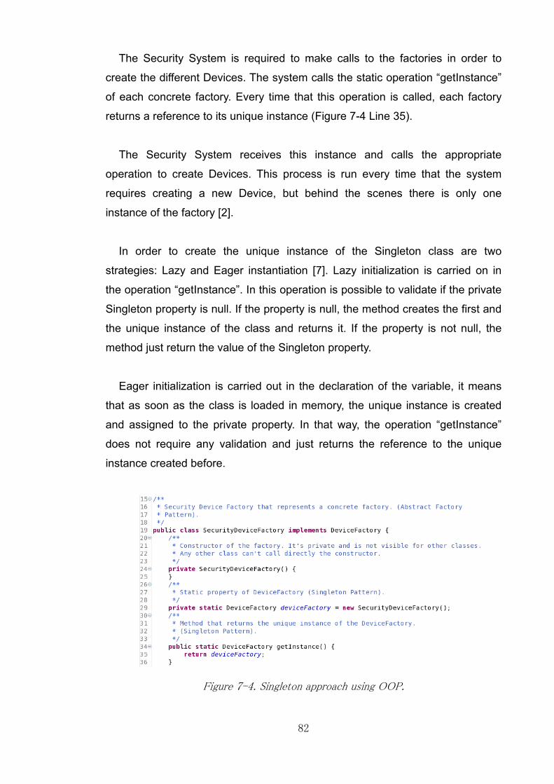
82
The Security System is required to make calls to the factories in order to
create the different Devices. The system calls the static operation “getInstance”
of each concrete factory. Every time that this operation is called, each factory
returns a reference to its unique instance (Figure 7-4 Line 35).
The Security System receives this instance and calls the appropriate
operation to create Devices. This process is run every time that the system
requires creating a new Device, but behind the scenes there is only one
instance of the factory [2].
In order to create the unique instance of the Singleton class are two
strategies: Lazy and Eager instantiation [7]. Lazy initialization is carried on in
the operation “getInstance”. In this operation is possible to validate if the private
Singleton property is null. If the property is null, the method creates the first and
the unique instance of the class and returns it. If the property is not null, the
method just return the value of the Singleton property.
Eager initialization is carried out in the declaration of the variable, it means
that as soon as the class is loaded in memory, the unique instance is created
and assigned to the private property. In that way, the operation “getInstance”
does not require any validation and just returns the reference to the unique
instance created before.
Figure 7-4. Singleton approach using OOP.
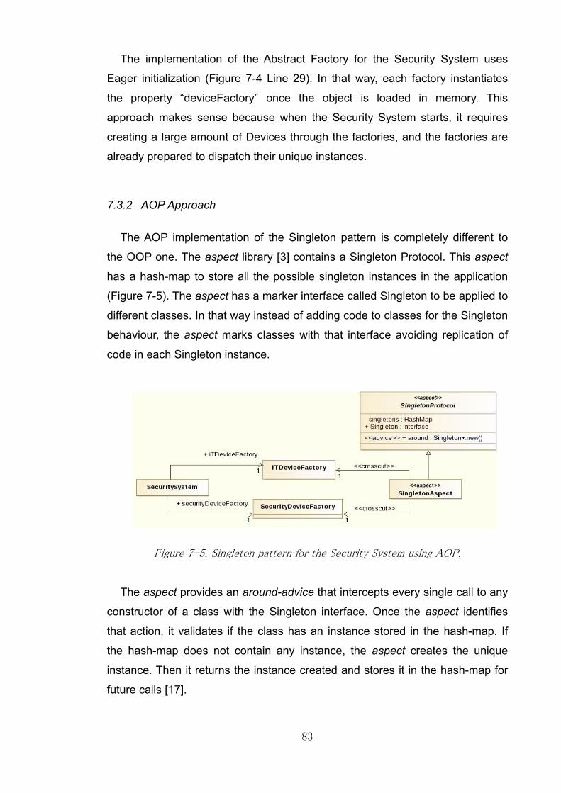
83
The implementation of the Abstract Factory for the Security System uses
Eager initialization (Figure 7-4 Line 29). In that way, each factory instantiates
the property “deviceFactory” once the object is loaded in memory. This
approach makes sense because when the Security System starts, it requires
creating a large amount of Devices through the factories, and the factories are
already prepared to dispatch their unique instances.
7.3.2 AOP Approach
The AOP implementation of the Singleton pattern is completely different to
the OOP one. The aspect library [3] contains a Singleton Protocol. This aspect
has a hash-map to store all the possible singleton instances in the application
(Figure 7-5). The aspect has a marker interface called Singleton to be applied to
different classes. In that way instead of adding code to classes for the Singleton
behaviour, the aspect marks classes with that interface avoiding replication of
code in each Singleton instance.
Figure 7-5. Singleton pattern for the Security System using AOP.
The aspect provides an around-advice that intercepts every single call to any
constructor of a class with the Singleton interface. Once the aspect identifies
that action, it validates if the class has an instance stored in the hash-map. If
the hash-map does not contain any instance, the aspect creates the unique
instance. Then it returns the instance created and stores it in the hash-map for
future calls [17].

84
A concrete aspect called Singleton Aspect is created in the system. This
aspect extends the Singleton Protocol, and the only code it contains is the
marking of the classes with the Singleton interface (Figure 7-6 Line 17 and 18).
In this particular scenario, the aspect attaches the Singleton interface to
Security Device Factory and IT Device Factory classes.
Figure 7-6. Marking classes with the Singleton interface in the aspect.
The AOP implementation of the Singleton pattern implies that the constructor
of the class marked as Singleton is public instead of private as in the OOP
approach (Figure 7-4 Line 24). In addition to that, the initialization of the unique
instance is Lazy with AOP. This is because the instances are created just until
the constructor of the Singleton class is invoked. This type of initialization
implies other issues related to performance and thread-safe access to the
around-advice.
7.4 Metrics Analysis
This section provides an analysis of the metric results for the two
implementations of the patterns using the AOP and OOP approaches (Table
7-1).
Separation of Concerns: In terms of the cross-cutting concerns, the Abstract
Factory does not show any improvement at all by using AOP. The CDC and
CDO metrics have a higher value in comparison with the OOP approach. This is
because AOP adds more classes (aspects) to execute the pattern code [39]. In
terms of the CDLOC metric, AOP reduces slightly the number of lines of code in
which the pattern code has the scattering and tangling effects.

85
The Singleton pattern adds two more aspects to the code (CDC metric).
However, this implementation reduces by 40% the scattering and tangling
effects (CDLOC). This is a significant reduction because the pattern code is
completely implemented in the aspects. Additionally, it removes from the
classes the “getInstance” operation, achieving a reduction in the number of
operations involved in the pattern code (CDO metric).
Metric Abstract Factory Singleton
OOP AOP OOP AOP
Concern Diffusion over Components (CDC) 8 10 4 6
Concern Diffusion over Operations (CDO) 8 10 5 2
Concern Diffusions over LOC (CDLOC) 22 18 40 24
Coupling Between Components (CBC) 16 16 22 18
Lines of Code (LOC) 143 159 238 167
Number of Attributes (NOA) 2 0 4 3
Weighted Operations per Component (WOC) 0 Parameters 4 0 7 4
1 Parameters 3 5 2 3
Table 7-1. Metrics results for the Abstract Factory and Singleton patterns.
Coupling: The AOP implementation reduces slightly the coupling between
components participating in these patterns (CBC metric). In the Abstract Factory
and the Singleton patterns the number of internal dependencies is less than the
number with the OOP implementation. Additionally, the hierarchical relationships
(DIT metric) are reduced in the Abstract Factory by one level. The factories do
not implement direct inheritance relationships with the abstract factory because
they are implemented in the aspects. The Singleton pattern does not require
any hierarchical relationships [2], however it increase the level of inheritance in
the classes due to the fact that includes a new aspect called Singleton Aspect
that has a hierarchical relationships with the Singleton Protocol (Table A-7).
Cohesion: In terms of cohesion (LCOO metric) the AOP implementation does
not provide any improvement for each pattern. In the OOP approach the IT
Device Factory and Security Device Factory are uncohesive because their
relationships between their properties and their number of operations are
unbalanced, and this behaviour is reflected with low values in this metric (Table
A-8).

86
In the AOP approach the classes do not have any implementation at all, but
this is not an improvement in the cohesion, just represents the effect of
allocating all the pattern code into the aspects.
Size: The AOP implementation reduces the number of operations in the
Abstract Factory (WOC metric). However, in the Singleton pattern the AOP
implementation includes one extra operation with more complexity in
comparison with the OOP. In general terms, there is no significant difference
between both implementations for these two patterns. The complexity of the
operations is not reduced with any of both implementations.
The number of attributes in the patterns (NOA metric) is reduced with AOP.
This is because in the OOP implementation, the factories have a property that is
part of the Singleton pattern. However, in the AOP implementation there is no
need to use that property.
The overall lines of codes (LOC metric) of the classes participating in the
Singleton pattern with AOP is reduced by nearly 30%. The Singleton is much
more reusable because it does not require to be replicated in all the possible
instances, all the code is controlled in the aspect Singleton Protocol and just a
few lines of code in the pattern instance are needed to set the unique classes.
The Abstract Factory increases the value of this metric with the AOP
implementation because this approach adds aspects without any reusable
purpose, just to put the code of the factory into the aspect. The factories classes
are still part of the code to decupled the Security System class from the
aspects.
7.5 Conclusions
The implementation of the Abstract Factory pattern using AOP does not give
any significant improvement. Basically, the aspect contains the same pattern
code as the OOP approach.

87
The AOP implementation applies the hierarchical relationships of the Abstract
Factory in the aspect, allowing concrete factories to receive a direct inheritance
relationship in the source code [3]. Apart from that feature, the metrics results
are similar to the OOP approach. This is not beneficial at all because the
factories are Pure Fabrications [1]. The only purpose of a factory is to create
objects. Removing the hierarchical relationships with the factory interface does
not give any improvement at all.
The AOP approach to the Singleton pattern changes the way in which this
pattern is usually implemented with OOP. This new approach declares which
classes are considered Singletons in the application, stores references to them,
and then intercepts all the possible calls to their constructors and returns always
the same reference previously created and stored for each of them.
This implementation is useful to reuse the behaviour of the Singleton pattern
without replicating the pattern code in all the possible instances of it. The
reusability of the pattern is maximised with the AOP implementation. It is
possible to have a large number of Singleton classes in the application without
duplicating the pattern code in each of them. This implementation is a clear and
a clean way to implement the pattern without affecting any class involved in it.

88
8 PATTERN INTERACTIONS
8.1 Overview
This section discusses some of the results obtained when two or more
patterns interact, or a class participates in more than one pattern. The idea is to
point out some of the effects of these pattern interactions with the AOP
implementations and draw some conclusions.
8.2 Pattern Dependencies
8.2.1 Strategy and Observer patterns
These two patterns interact closely in the Security System. The Observer
pattern provides the functionalities of removing/adding Observers from/to the list
allocated in each Subject [2]. In the case of the Security System, the observers
are Local Stations and Remote Stations and the subjects are concrete Devices.
In addition to that, the Strategy pattern based on some business rules
removes/adds stations from/to the list of each Device.
In the OOP approach this interaction is clear because the Strategy pattern
receives the list of Devices from a specific station, and then removes/adds the
station from/to the list of each Device, because the list of observers is
associated directly to each Device (Figure 8-1 Lines 48 and 51).
Figure 8-1. Modifying the list of observers with the OOP approach.

89
However, with the AOP implementation this is not possible. The list of
observers is not part of the Device because it is managed by the aspects [3].
This means that the concrete strategies need to be coupled with the aspects
that manage the observer instances (Figure 8-2 Lines 52 and 56). This kind of
coupling makes the Strategy pattern code difficult to understand and maintain,
because the pattern now depends on another set of aspects, producing the
tangling effect [39].
In fact, the strategies are classes that could be part of the domain because
they represent different algorithms to be executed in the application. In this
case, the AOP pattern is mixed with the domain classes creating the tangling
and scattering effects for the pattern code. It seems that the AOP
implementation in these kinds of situations does not help to isolate the cross-
cutting concern at all.
Figure 8-2. Modifying the list of observers with the AOP approach.
Additionally, all the roles of the Observer pattern such as Subject and
Observer are contained in the aspects as marker interfaces. If the source code
requires validating an object against these roles (for example a casting
validation), it requires now an extra dependency on the aspects in order to
access these interfaces. These new dependencies are scattered in all the
possible places of the code where this kind of validations are needed (Figure
8-2 Line 48).

90
8.2.2 Abstract Factory and Singleton patterns
The OOP implementation of the Singleton pattern requires imposing some
properties and operations on the factories. Once these features are added into
the factories, the clients of the factories have to use them to interact with them
[7].
On the other hand, the AOP implementation changes completely the
Singleton pattern. The Abstract Factory does not have any substantial change
with the AOP, just moving the pattern code into the new aspects. However, the
AOP implementation of the Singleton pattern is much more flexible than the
OOP one. It does not impose any features (properties or operations) on the
factories, keeping the pattern code isolated and reusable.
8.2.3 Template and Proxy patterns
The Template pattern uses the Monitoring Station in order to implement the
Template Method and its concrete operations. The Proxy pattern uses the
Monitoring Station as the common interface for the Proxy, Local and Remote
Stations. The interactions between these two patterns are complex in terms of
the Proxy pattern.
The AOP implementation of the Proxy pattern requires intercepting the
operations of the Monitoring Station in an aspect. At the same time the aspect
has to differentiate between intercepted operations from Local and Remote
Stations. This is possible with a proper definition of join-points and point-cuts in
the aspect, but is not an easy task.
This complexity is created because the Proxy pattern intercepts the
operations of the appropriate class and then redirects the method invocations to
the Remote Station. The interactions between these two patterns are not easy
to understand because some operations of the Remote Station are declared in
the class and other are declared directly in the aspects through the Template
pattern, so the point-cut declarations are complex.

91
8.2.4 Composite pattern
This pattern creates a tree-like structure in the core domain classes
(Devices). Most of the patterns in the system interact with these core domain
classes to manage specific scenarios. A simple change in the code of the
Composite pattern is reflected in the rest of the application.
Using OOP the interaction between the Composite and the other patterns is
clear due to the fact that the Composite pattern is part of the structure of these
core domain classes (Devices). All the system knows the abstract Device class
and its dependant classes, so it is possible to manipulate and to interact with
the tree-like structure easily. For example, the Local Station with the operation
“startStation” uses recursion to traverse the tree-like structure. This recursive
operation calls the list of Devices for each Device Group directly due to the fact
that the list is attached to the Device Group class (Figure 8-3 Line 47).
Figure 8-3. Accessing children devices of the Device Group with OOP.
On the other hand, the AOP implementation manages the Composite
structure completely differently. First of all the new structure of the pattern is
managed in the aspects, it is a tree-like structure with one more level of
indirection (hash-map).

92
It means that other classes in the system require the Composite aspects in
order to traverse the new composition of Devices. The traversing mechanism is
not trivial and must be managed by the aspect. If any other class or pattern in
the system needs to go through the composite structure, they need to have a
relationship with the aspect and use the operations that it provides for traversing
the composition of Devices. The Local Station of the AOP approach now has a
new dependency with the Composite Device Aspect in order to access the list of
Devices of each Device Group (Figure 8-4 Line 49). Additionally, it has to
perform a transformation of data types using extra utility classes to convert the
return type into a Java List (Figure 8-4 Line 51).
Figure 8-4. Accessing children devices of the Device Group with AOP.
The impact of this change is high because nearly all of the classes and
patterns are coupled with the Composite aspect. This level of coupling is difficult
to maintain because a simple change in the aspect could cause side effects in
others patterns or domain classes. This is one of the most critical effects
identified in the AOP implementation of the pattern with the described business
scenarios.
93
8.3 Domain Classes
The AOP implementations of the patterns help to improve the cohesion of the
classes that participates in the patterns, specifically the domain classes. Some
of these classes take part in different patterns, but at the same time, thanks to
the AOP features these classes remain unaware of any pattern code, remaining
cohesive and easy to maintain [13].
This is a positive feature of the AOP implementations, since it helps to
improve the cohesion of the domain classes. Specific examples in the Security
System are described as follows.
8.3.1 Monitoring Stations
The Monitoring Station is a class that participates in different patterns. The
Template pattern uses this class to represent the abstract class that contains
the Template Method. The Observer pattern uses this class to play the role of
Observer. The Proxy pattern uses this class as the interface for both the Proxy
and the Remote stations.
The AOP implementations of these three patterns provide a flexible way in
which this class participates in the patterns. The pattern code relies in the
aspects developed for each pattern. It means that the class remains clean of
any pattern code in it. This is an advantage due to the fact the structure and the
purpose of the class remains clear from the domain analysis [12].
Moreover, there is no need to impose any additional pattern code in the class
to fulfil the pattern requirements. The locality of the pattern is isolated in the
aspects and the class remains unaware of the cross-cutting concerns that the
pattern code represents (apart from the side effect mentioned in the Template
and Proxy patterns).

94
8.3.2 Local and Remote Stations
These two classes from the domain analysis participate in different design
patterns. The Local Stations are part of the Command and the Observer
patterns. The Remote Stations are part of the Adapter and the Observer
pattern.
The AOP implementation provides the code for these patterns in the aspects
developed and these classes are not affected at all by complex pattern
interactions [3] (apart from the side effect mentioned for the Composite pattern).
The AOP implementation isolates the pattern code and it is possible to have
free-pattern-code domain classes. There are some operations of these stations
that participate in the patterns, but they contain business rules and domain
business logic. In general terms the classes remain clean of any pattern code
imposed.

95
9 CONCLUSIONS AND FUTURE WORK
9.1 Conclusions
In general terms, AOP is a paradigm that works closely with the OOP one
and helps to solve some of its limitations [3]. OOP languages such as Java
have the restriction of the single direct inheritance and multiple inheritance
through interface implementation. This restriction is sensible most of the time
due to the fact that multiple inheritance has been overused causing complex
problems in code.
In some cases is possible to overcome this restriction by using AOP features.
AOP provides a mechanism to apply hierarchical relationships to classes
without modifying source code [17]. However, this feature of AOP should be
managed carefully because it allows software developers to apply multiple
behaviours to classes. These behaviours are not easily visible because they are
applied in the aspects, so developers have to be aware of the extra behaviour
of a class outside of the class itself. Moreover, based on the results of this
project this feature should be used just in some specific and particular scenarios
in order to avoid creating complex code in the aspects.
The combination of the Design Patterns [2] and AOP is an interesting area of
software engineering, because it is possible to analyse the behaviour of the
AOP features and the cross-cutting concerns present in the patterns and draw
some conclusions. However, based on the outcome of this project not all the
pattern implementations with AOP are successful, most of them create side
effects in code that are not easy to understand and maintain.
The selection criteria for all the patterns in the Security System scenarios are
based on the suitability of the pattern in the domain, and the list of design
patterns that could be improved by using AOP. This project implements 9
patterns, 8 of which are among of the 17 patterns listed that are claimed to
improve with the AOP implementation [3].

96
However, based on the implementations and the metric analysis just two
patterns (Observer and Singleton) give obvious improvements in their AOP
implementations. In the 7 remaining patterns, some of them involve Pure
Fabrications [1] that do not give any advantage at all (Abstract Factory, Adapter
and Template). Their AOP implementations are based on moving the code into
new aspects without any real change in the pattern code. Other patterns
present some features of reusability and locality of the pattern code (Strategy,
Command, Composite and Proxy) that could be considered as an advantage in
comparison with the OOP approach in some specific conditions and scenarios.
The pattern structures of the AOP implementations are different in most of
the cases. Therefore, classes that need to interact with the pattern (domain
classes, indirections or aspects) require new dependencies with the aspects
that contain the pattern code. This effect creates more coupled classes and
increases the number of dependencies between them.
It is claimed that the AOP helps to reduce the properties and operations
imposed by the patterns with the OOP approach [3]. This is partially true
because the AOP implementations of the patterns rely completely on the
aspects, and domain classes do not require adding properties and operations
that are part of the pattern. In addition to that, the pattern code (considered as
the cross-cutting concern) is isolated in the aspects, avoiding completely the
tangling and scattering effects in the code. The AOP approach helps to keep the
domain classes clean of any pattern code even when the classes are
participating in more than one pattern, improving their cohesion and
maintenance.
However, the increase of the cohesion in the domain classes is achieved
through a complex and tangled aspect. In fact, most of the aspects have the
worst values in the cohesion metric. Basically, based on the implementations
developed in this project, AOP helps to improve slightly the cohesion of the
domain classes by using uncohesive aspects.

97
To sum up, there are some features of the AOP that help to manage in a
better way the cross-cutting concerns of the pattern code. However, the AOP
approach implies more coupled and uncohesive aspects in its pattern
implementations. This new approach requires a good understanding of all the
features that AOP provides and a high level of abstraction of the pattern
implementation.
9.2 Recommendations
On the basis of this project, it appears that there is no reason to apply AOP to
implement the design patterns that involve Pure Fabrications [1] features for the
multiple inheritance issue. In these specific scenarios the pattern code is moved
into the aspects and there is no significant advantage of doing that.
On the contrary, the number of dependencies between the domain classes
and the aspects increase with more coupled classes in these particular
scenarios. However, in some particular scenarios, the Pure Fabrication features
could be scattered in the code, meaning that is possible to use features of AOP
(point-cuts and advice) to remove these effect.
However, if a scenario involves classes from the domain with specific
business logic and at the same time pattern logic, the AOP implementation is a
good approach to removing the pattern code from the classes and improving
their cohesion (for example in the Observer pattern). In this scenario the AOP
implementation isolates the pattern code in the aspects and avoids the tangling
and scattering effects in the code. Additionally, the reusability of the pattern
code is improved, meaning that future changes in the rules of the pattern are
easy to implement.
In terms of the metric suite, it gives reasonable guidelines to analyse the
code with both approaches. The selected metric suite has been used in similar
studies related to code comparisons between OOP and AOP approaches.

98
However, not all the metrics give useful information for assessing the pattern
code. There are different studies that show a wide range of metrics to apply for
OOP but not all of them are really useful to draw concrete conclusion in terms of
the pattern implementations and to analyse deeply the AOP features.
Metrics such as Concern Diffusion over Components (CDC), Concern
Diffusion over Operations (CDO) and Concern Diffusion over Lines of Code
(CDLOC) are really useful to analyse how the cross-cutting concerns (in this
case the pattern code) are present in the code. The Coupling between
Components (CBC) metric gives a good assessment of how coupled a
component is in terms of its relationships and dependencies. The Lack of
Cohesion in Operations (LCOO) metric gives an overview of how cohesive a
component is in terms of its attributes and operations, but there are multiple
ways to assess these properties. In that way the results could be interpreted
and analysed in different ways with different outcome.
On the other hand, the metrics in the Size category such as Lines of Code
(LOC), Number of Attributes (NOA) or Weighted Operations per Component
(WOC) do not provide significant information at all. These metrics provide a
general idea of the size of the code but without any complexity feature involved.
A general rule is less lines of code represent better code. However, in the
scenarios analysed, most of the times when the metrics show less lines of code,
the code is more complex and difficult to understand. The Depth of Inheritance
Tree (DIT) metric makes sense when the pattern implies generalisation and
when the hierarchical relationships are a big issue in the modelling.
9.3 Future Work
UML and AOP: This project works with one of the approaches to combine the
UML and AOP features. However, this area of research is still ongoing and
different surveys show advantages and disadvantages depending on the AOP
implementation, tool support, code generation, maturity, etc [36].

99
It seems that it is worthy to evaluate and analyse this topic in more detail in
order to investigate which kinds of tools are supporting Aspect Oriented
Modelling to represent properly the AOP features.
Actually, Aspect Oriented Modelling is an active area of research. There are
different initiatives and research about how to combine all the features of the
Aspect Oriented paradigm in software architectures [21] and cross-cutting
concerns in high level designs [43]. It seems that the Aspect Oriented paradigm
is being developed in this direction as well as the code implementations.
AOP patterns: Most of the features of AOP are quite powerful in terms of
code interception and cross-cutting concern isolation [16]. However, since its
inception and during these years of different implementations, there are some
best practices related to the AOP. These guidelines are called “AOP Patterns”
and allow software developers to use the features of this paradigm in an
appropriate way [30]. These patterns should be explored in detail in order to
identify possible future application or combinations with the well known design
patterns.
Alternative Pattern Implementations: The project implements the design
patterns following the guidelines and examples developed in the aspect library
[3]. These guidelines give an approach to implement the patterns by using “role
separation” analysis and pattern code locality [10]. The project developed all the
patterns with this approach and this library because this approach is part of the
outcome of the research that claims the improvement of the patterns with AOP.
However, this is not the only approach to do it. AOP provides features to
implement the design patterns in different ways with a variety of approaches. It
is possible to explore new ways to implement the patterns with AOP and
investigate if there are new implementations that overcome the OOP limitations
and the side effects that AOP produces in the code in the scenario evaluated in
this project.

100
Metrics: The previous section mentions that not all the metrics selected for
the evaluation are good enough for showing particular features in AOP and
OOP. This is an area of research that is still active and it seems that is evolving
to a more complex metrics analysis [43]. Researchers are working on
evaluating advanced modularization techniques such as Aspect Oriented
Modelling and Aspect Oriented Software Design [43].
The metrics used in this project analysed the code according to the most
relevant characteristics of the OOP and AOP. Based on the results of this
project, most of the metrics tend to show an improvement in these
characteristics.
However, the AOP implementations have different side effects in code and
other drawbacks analysed in the previous sections that are not shown by the
metrics. It seems that the metrics are not well developed to explain the
complexity of AOP.
Most of the metrics assess the AOP implementation in terms of the
properties, operations (OOP features) and in some cases advice (an AOP
feature). However, the complexity of AOP includes others important features
such as point-cuts, the weaving process, code injection and complex advice
such as around-advice. These features should be explored in order to identify
which set of metrics are appropriate to understand and analyse the AOP
features.
In addition to that, the project used a plug-in for Eclipse IDE, but not all of the
features are well developed for AOP. The plug-in calculates a wide range of
metrics for OOP, but it seems that it does not work properly for AOP features
such as advice and point-cuts. In the end the project used manual calculation
and formulation for all of the metrics selected. An exploration of tools and plug-
in for AOP metrics should be carried out in order to apply them in similar
analysis and future projects.

101
In summary, the implementation of design patterns by using AOP in most of
the cases is based on moving the complexity and concerns of the pattern from
one place to another (classes to aspects). This approach provides potential
benefits in a couple of patterns; benefits such as pattern code locality or making
domain classes more cohesive.
However, for the rest of the patterns this approach causes side effects in
code such as highly coupled domain classes and uncohesive aspects.
Sometimes is better to leave the complexity of patterns in the classes rather
than move it into another place. This project has shown an approach of the
patterns by using AOP, but it points out some potential areas of future work in
which AOP can be investigated and applied in more detail.
102
10 REFERENCES
[1] Craig Larman, Applying UML and Patterns - An Introduction to Object-
Oriented Analysis and Design and the Unified Process.: Prentice Hall,
2005.
[2] Erich Gamma, Richard Helm, Johnson Ralph, and Vlissides John, Design
Patterns: Elements of Reusable Object-Oriented Software.: Addison
Wesley Longman Inc., 1995.
[3] Jan Hannemann and Gregor Kiczales, "Design Pattern Implementation in
Java and AspectJ," Object-Oriented Programming, Systems, Languages &
Applications OOPSLA, 2002.
[4] Gregor Kiczales et al., "An Overview of AspectJ," European Conference on
Object-Oriented Programming ECOOP, 2001.
[5] George William Howarth, "An Investigation into Aspect-Oriented
Programming," School of Computer Science. The University of Manchester,
MSc Dissertation 2012.
[6] Danny Poo, Derek Kiong, and Swarnalatha Ashok, Object Oriented
Programming and Java, 2nd ed.: Springer, 2008.
[7] Eric Freeman, Elisabeth Freeman, Kathy Sierra, and Bert Bates, Head First
Design Patterns.: O’Reilly Media Inc, 2004.
[8] Hidehiko Masuhara and Gregor Kiczales, "Modeling Crosscutting in Aspect-
Oriented Mechanisms," European Conference on Object-Oriented
Programming ECOOP, 2003.
[9] Sarmad Ali Muhammad, Ali Babar Muhammad, Chen Lianping, and Stol
Klaas-Jan, "A Systematic Review of Comparative Evidence of Aspect-
Oriented Programming," Information and Software Technology, vol. 52,
2010.
[10] Jan Hannemann, Gail C Murphy, and Gregor Kiczales, "Role-Based
Refactoring of Crosscutting Concerns," Aspect-Oriented Software
Development AOSD, 2005.
[11] Steven John Metsker, Design Patterns Java Workbook.: Addison Wesley,
2002.

103
[12] Ouafa Hachani and Daniel Bardou, "Using Aspect-Oriented Programming
for Design Patterns Implementation," in In Proc. Workshop Reuse in
Object-Oriented Information Systems Design, Montpellier, France, 2002.
[13] Nicholas Lesiecki. (2005, May) Developerworks - AOP@Work: Enhance
design patterns with AspectJ. [Online].
http://www.ibm.com/developerworks/library/j-aopwork5/. Last Accessed:
(2013-May-03)
[14] Pavol Baca and Valentino Vranic, "Replacing Object-Oriented Design
Patterns with Intrinsic Aspect-Oriented Design Patterns," Faculty of
Informatics and Information Technologies. Slovak University of Technology,
Bratislava, 2011.
[15] Gregor Kiczales et al., "Aspect-Oriented Programming," European
Conference on Object-Oriented Programming ECOOP, vol. 1241, 1997.
[16] Joseph D Gradecki and Nicholas Lesiecki, Mastering AspectJ: Aspect-
Oriented Programming in Java.: Wiley Publishing, Inc, 2003.
[17] Russ Miles, AspectJ Cookbook: Aspect Oriented Solutions to Real-World
Problems.: O'Reilly Media Inc, 2004.
[18] Gregor Kiczales and Mira Mezini, "Separation of Concerns with
Procedures, Annotations, Advice and Pointcuts," European Conference on
Object-Oriented Programming ECOOP, vol. 3586, 2005.
[19] Ivan Kiselev, Aspect-Oriented Programming with AspectJ.: Sams
Publishing, 2003.
[20] Terry Hon and Gregor Kiczales , "Fluid AOP Join Point Models," Object-
Oriented Programming, Systems, Languages & Applications OOPSLA,
2006.
[21] Elisa Y Nakagawa, Fabiano C Ferrari, Mariela M.F Sasaki, and José C
Maldonado, "An Aspect-Oriented Reference Architecture for Software
Engineering Environments," The Journal of Systems and Software, vol. 84,
2011.
[22] Peng Wang and Xiaochun Zhao, "The Research of Automated Select Test
Cases for Aspect-oriented Software," Information Engineering Research
Institute, 2012.

104
[23] Ryan M Golbeck, Samuel Davis, Immad Naseer, Igor Ostrovsky, and
Gregor Kiczales, "Lightweight Virtual Machine Support for AspectJ,"
Aspect-Oriented Software Development AOSD, 2008.
[24] Ryan M Golbeck, Peter Selby, and Gregor Kiczales, "Late Binding of
AspectJ Advice," Lecture Notes in Computer Science LNCS, vol. 6141,
2010.
[25] Éric Tanter, Rodolfo Toledo, Guillaume Pothier, and Jacques Noyé,
"Flexible metaprogramming and AOP in Java," Science of Computer
Programming, vol. 72, 2008.
[26] Mitchell Wand and Gregor Kiczales, "A Semantics for Advice and Dynamic
Join Points in Aspect-Oriented Programming," Transactions on
Programming Languages and Systems TPLS, vol. 26, 2004.
[27] Pasquale Arpaia, Mario Luca Bernardi, Giuseppe Di Lucca, Vitaliano
Inglese, and Giovanni Spiezia, "An Aspect-Oriented Programming-based
approach to software development for fault detection in measurement
systems," Computer Standards & Interfaces, vol. 32, 2010.
[28] Javier Camara, Carlos Canal, Javier Cubo, and Juan Manuel Murillo, "An
Aspect-Oriented Adaptation Framework for Dynamic Component
Evolution," Electronic Notes in Theoretical Computer Science, vol. 189,
2007.
[29] Kevin Hoffman and Patrick Eugster, "Cooperative aspect-oriented
programming," Science of Computer Programming, vol. 74, 2009.
[30] James Noble, Arno Schmidmeier, David J Pearce, and Andrew P Black,
"Patterns of Aspect-Oriented Design," European Conference on Pattern
Languages of Programs. EuroPLoP, 2008.
[31] Mohamed Kandé, Jörg Kienzle, and Alfred Strohmeier, "From AOP to UML:
Towards an Aspect-Oriented Architectural Modeling Approach," Software
Engineering Laboratory. Swiss Federal Institute of Technology Lausanne,
Switzerland, 2002.
[32] Zhang Zhang, Guangyuan Liu, and Yuejuan Chen, "Modeling Aspect-
Oriented Programming with UML Profile," First International Workshop on
Education Technology and Computer Science, 2009.
[33] Omar Aldawud, Tzilla Elrad, and Atef Bader, "A UML Profile for Aspect

105
Oriented Modeling," Workshop on Aspect Oriented Programming.
OOPSLA, 2001.
[34] Georg Geri and Robert France, "UML Aspect Specification Using Role
Models," Object-Oriented Information Systems. Lecture Notes in Computer
Science, vol. 2425, 2002.
[35] Shaukat Ali Khan and Aamer Nadeem, "UML Extensions for Modeling of
Aspect Oriented Software: A Survey," Proceedings of the 2010 National
Software Engineering Conference, 2010.
[36] Manuel Wimmer et al., "A Survey on UML-Based Aspect-Oriented Design
Modeling," ACM Computing Surveys, vol. 43, no. 4, 2011.
[37] Dominik Stein, Stefan Hanenberg, and Rainer Unland, "An UML-based
Aspect-Oriented Design Notation For AspectJ," AOSD Proceedings of the
1st international conference on Aspect-oriented software development,
2002.
[38] Walter Binder, Danilo Ansaloni, Alex Villazón, and Philippe Moret, "Flexible
and efficient profiling with aspect-oriented programming," Concurrency And
Computation: Practice And Experience. Wiley Online Library, 2011.
[39] Nelio Cacho et al., "Composing Design Patterns: A Scalability Study of
Aspect-Oriented Programming," Aspect-Oriented Software Development
AOSD, 2006.
[40] Fernando Castor Filho, Ceciılia Mary F. Rubira, and Alessandro Garcia, "A
Quantitative Study on the Aspectization of Exception Handling," Institute of
Computing - State University of Campinas, 2006.
[41] Alessandro Garcia et al., "Modularizing Design Patterns with Aspects: A
Quantitative Study," Computer Science Department. Pontifical Catholic
University of Rio de Janeiro, Rio de Janeiro, 2005.
[42] Claudio Sant’Anna, Alessandro Garcia, Christina Chavez, Carlos Lucena,
and Arndt Von Staa, "On the Reuse and Maintenance of Aspect-Oriented
Software: An Assessment Framework," Proc. of Brazilian Symposium on
Software Engineering (SBES-03), 2003.
[43] Cláudio Nogueira Sant’Anna, "On the Modularity of Aspect-Oriented
Design: A Concern-Driven Measurement Approach," Pontifica Universidade
Catolica do Rio de Janeiro. Computer Science Department., Rio de

106
Janeiro, PhD Thesis 2008.
[44] Arjun Singh and Gregor Kiczale, "The Scalability of AspectJ," University of
British Columbia, 2007.
[45] Adrian Colyer, Andy Clement, George Harley, and Matthew Webster,
Eclipse AspectJ: Aspect-oriented Programming with AspectJ and the
Eclipse AspectJ Development Tools.: Addison-Wesley, 2004.
[46] Laurie Williams. (2008) An Introduction to Object-Oriented Metrics. [Online].
http://agile.csc.ncsu.edu/SEMaterials/OOMetrics.htm. Last Accessed:
(2013-08-30)
[47] Letha Etzkorn, Carl Davis, and Wei Li, "A Statistical Comparison of Various
Definitions of the LCOM Metric," The University of Alabama in Huntsville,
Alabama, 1997.

APPENDIX
PPENDIX A: METRICS
Table A-1
Figure A
ETRICS RESULTS
Pattern
Observer
Composite
Command
Abstract Factory
Singleton
Adapter
Strategy
Proxy
Template
1. Concern Diffusion over Components (CDC
Figure A-1. B
107
ESULTS
Pattern Number of Components
Observer
Composite
Command
Abstract Factory
Singleton
Template
. Concern Diffusion over Components (CDC
Bars diagram
107
Number of Components
OOP
12
9
14
8
4
8
9
4
4
. Concern Diffusion over Components (CDC
ars diagram with the CDC metric.
Number of Components
AOP
7
13
19
10
6
11
9
6
6
. Concern Diffusion over Components (CDC
with the CDC metric.
. Concern Diffusion over Components (CDC metric).
with the CDC metric.

Table A-
Figure A
Pattern
Observer
Composite
Command
Abstract Factory
Singleton
Adapter
Strategy
Proxy
Template
-2. Concern Diffusion over Operations (CDO
Figure A-2. Bars diagram with the
108
Pattern Number of Operations
Observer
Composite
Command
Abstract Factory
Singleton
Adapter
Strategy
Template
Concern Diffusion over Operations (CDO
Bars diagram with the
108
Number of Operations
OOP
22
18
29
8
5
30
16
26
11
Concern Diffusion over Operations (CDO
Bars diagram with the
Number of Operations
AOP
11
21
32
10
2
21
15
19
10
Concern Diffusion over Operations (CDO
Bars diagram with the CDO metric
Concern Diffusion over Operations (CDO metric).
CDO metric.
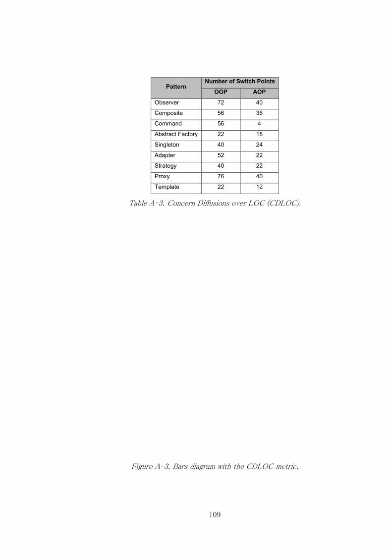
Table A
Figure A
Pattern
Observer
Composite
Command
Abstract Factory
Singleton
Adapter
Strategy
Proxy
Template
Table A-3. Concern Diffusions over LOC (CDLOC)
Figure A-3. Bars diagram with the CDLOC metric.
109
Pattern Number of Switch Points
Observer
Composite
Command
Abstract Factory
Singleton
Template
Concern Diffusions over LOC (CDLOC)
Bars diagram with the CDLOC metric.
109
Number of Switch Points
OOP
72
56
56
22
40
52
40
76
22
Concern Diffusions over LOC (CDLOC)
Bars diagram with the CDLOC metric.
Number of Switch Points
AOP
40
36
4
18
24
22
22
40
12
Concern Diffusions over LOC (CDLOC)
Bars diagram with the CDLOC metric.
Concern Diffusions over LOC (CDLOC).
Bars diagram with the CDLOC metric.

Table A
Figure A
Pattern
Observer
Composite
Command
Abstract Factory
Singleton
Adapter
Strategy
Proxy
Template
Table A-4. Coupling Between Components (CBC)
Figure A-4. Bars diagram with the CBC metric.
110
Pattern Number of Dependencies
Observer
Composite
Command
Abstract Factory
Singleton
Template
Coupling Between Components (CBC)
Bars diagram with the CBC metric.
110
Number of Dependencies
OOP
65
44
25
16
22
26
31
9
36
Coupling Between Components (CBC)
Bars diagram with the CBC metric.
Number of Dependencies
AOP
84
54
31
16
18
23
46
5
35
Coupling Between Components (CBC)
Bars diagram with the CBC metric.
Coupling Between Components (CBC)
Bars diagram with the CBC metric.

Figure A
Pattern
Observer
Composite
Command
Abstract Factory
Singleton
Adapter
Strategy
Proxy
Template
Table A
Figure A-5. Bars diagram with the LOC metric.
111
Pattern Number of Lines of Code
Observer
Composite
Command
Abstract Factory
Singleton
Template
Table A-5. Lines of Code (LOC)
Bars diagram with the LOC metric.
111
Number of Lines of Code
OOP
663
519
167
143
238
347
187
102
267
Lines of Code (LOC)
Bars diagram with the LOC metric.
Number of Lines of Code
AOP
740
572
230
159
167
350
301
90
239
Lines of Code (LOC)
Bars diagram with the LOC metric.Bars diagram with the LOC metric.
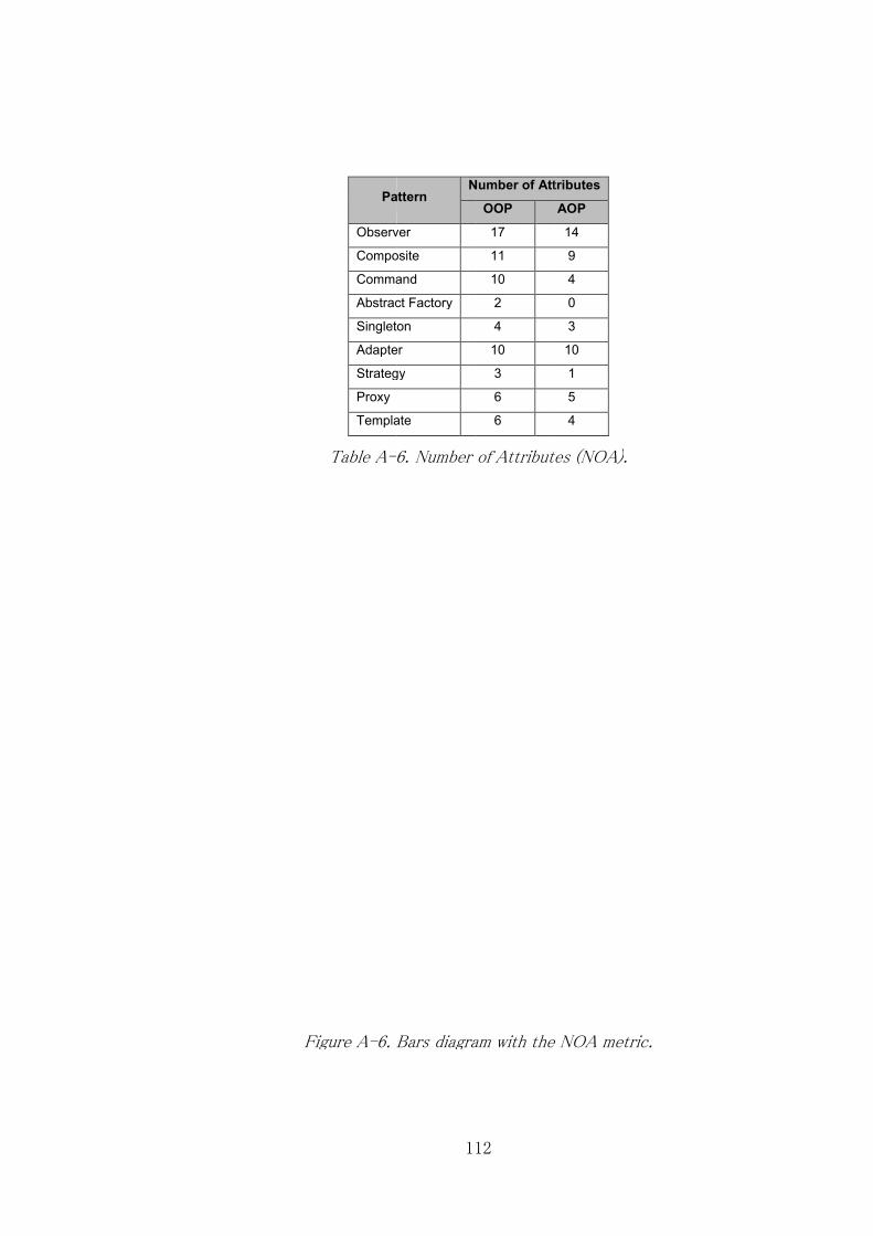
Figure A
Pattern
Observer
Composite
Command
Abstract Factory
Singleton
Adapter
Strategy
Proxy
Template
Table A-6
Figure A-6. Bars diagram with the NOA metric.
112
Pattern Number of Attributes
Observer
Composite
Command
Abstract Factory
Singleton
Adapter
Strategy
Template
6. Number of Attributes (NOA)
Bars diagram with the NOA metric.
112
Number of Attributes
OOP
17
11
10
2
4
10
3
6
6
Number of Attributes (NOA)
Bars diagram with the NOA metric.
Number of Attributes
AOP
14
9
4
0
3
10
1
5
4
Number of Attributes (NOA).
Bars diagram with the NOA metric.
Bars diagram with the NOA metric.

113
Pattern
Approach
OOP AOP
Class Inheritance Class Inheritance
Observer
Camera
SecurityDevice
4 Camera
SecurityDevice
3 SingleDeive SingleDeive
Device Device
Subject
RoomSensor
SecurityDevice
4 RoomSensor
SecurityDevice
3 SingleDeive SingleDeive
Device Device
Subject
SecurityDoor
SecurityDevice
4 SecurityDoor
SecurityDevice
3 SingleDeive SingleDeive
Device Device
Subject
LocalStation MonitoringStation
2 LocalStation MonitoringStation
1 Observer
RemoteStation MonitoringStation
2 RemoteStation MonitoringStation
1 Observer
RemoteStationObserverAs
pect ObserverProtocol 1
LocalStationObserverAspe
ct ObserverProtocol 1
Composite
DeviceGroup Device 1 DeviceGroup 0
SingleDevice Device 1 SingleDevice 0
CompositeDevicesAspect CompositeProtocol 1
Command
CameraStartRecordi
ng Command 1 CameraStartRecording 0
CameraStopRecordi
ng Command 1 CameraStopRecording 0
RoomSensorActivat
e Command 1 RoomSensorActivate 0
RoomSensorDeactiv
ate Command 1 RoomSensorDeactivate 0
SecurityDoorActivat
e Command 1 SecurityDoorActivate 0
SecurityDoorDeactiv
ate Command 1 SecurityDoorDeactivate 0
ControlPanelCommandsO
ffAspect CommandProtocol 1
ControlPanelCommandsO
nAspect CommandProtocol 1
Abstract
Factory
ITDeviceFactory DeviceFactory 1 ITDeviceFactory
0
SecurityDeviceFacto
ry DeviceFactory 1 SecurityDeviceFactory
0
SecurityDevice SingleDevice 1 SecurityDevice SingleDevice 1
ITDevice SingleDevice 1 ITDevice SingleDevice 1
Singleton
SingletonAspect SingletonProtocol 1

114
Pattern
Approach
OOP AOP
Class Inheritance Class Inheritance
Adapter
CSVReportAdapter ReportHandler 1 CSVReportAdapter
0
TXTReportAdapter ReportHandler 1 TXTReportAdapter
0
XMLReportAdapter ReportHandler 1 XMLReportAdapter
0
CSVReportAdapterAspect
0
TXTReportAdapterAspect
0
XMLReportAdapterAspect
0
Strategy
DayMode MonitoringStrategy 1 DayMode
0
NightMode MonitoringStrategy 1 NightMode
0
WeekdayMode MonitoringStrategy 1 WeekdayMode
0
WeekendMode MonitoringStrategy 1 WeekendMode
0
MonitoringStrategyAspect StrategyProtocol 1
Proxy
ProxyStation MonitoringStation 1 ProxyStation
0
RemoteStation MonitoringStation 1 RemoteStation MonitoringStation 1
ProxyStationAspect ProxyProtocol 1
Template RemoteStation MonitoringStation 1 RemoteStation MonitoringStation 1
LocalStation MonitoringStation 1 LocalStation MonitoringStation 1
Table A-7. Depth of the Inheritance Tree (DIT metric).

115
Pattern Class/Aspect Approach
OOP AOP
Observer
Camera 0.795 0.750
RoomSensor 0.795 0.750
SecurityDoor 0.818 0.792
MonitoringStation 0.778 0.667
LocalStation 0.500 0.333
RemoteStation 1.000 1.000
ObserverProtocol N/A 1.000
LocalStationObserverAspect N/A N/A
RemoteStationObserverAspect N/A N/A
Composite
Device 0.800 0.667
DeviceGroup 0.417 0.500
SingleDevice 0.813 0.800
CompositeProtocol N/A 1.000
CompositeDevicesAspect N/A N/A
Command
ControlPanel 0.500 N/A
CameraStartRecording 0.500 N/A
CameraStopRecording 0.500 N/A
RoomSensorActivate 0.500 N/A
RoomSensorDeactivate 0.500 N/A
SecurityDoorActivate 0.500 N/A
SecurityDoorDeactivate 0.500 N/A
CommandProtocol N/A 0.833
ControlPanelCommandsOffAspect N/A N/A
ControlPanelCommandsOnAspect N/A N/A
Abstract Factory
ITDeviceFactory 1.000 N/A
SecurityDeviceFactory 1.000 N/A
ITDeviceFactoryAspect N/A N/A
SecurityDeviceFactoryAspect N/A N/A
Singleton SingletonProtocol N/A 0.000
SingletonAspect N/A N/A
Adapter
CSVReport 0.667 0.667
TXTReport 0.500 0.500
XMLReport 0.500 0.500
CSVReportAdapter 0.000 N/A
TXTReportAdapter 0.000 N/A
XMLReportAdapter 0.000 N/A
CSVReportAdapterAspect N/A 0.000
TXTReportAdapterAspect N/A 0.000
XMLReportAdapterAspect N/A 0.000
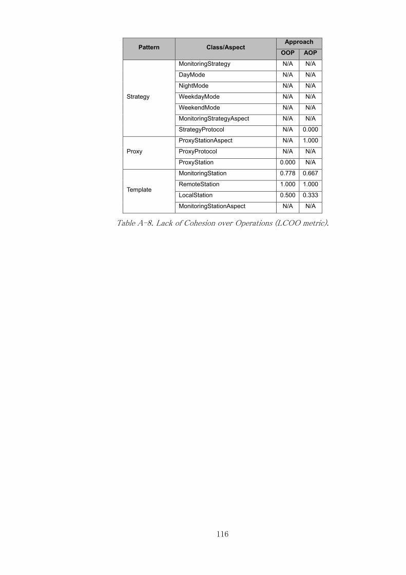
116
Pattern Class/Aspect Approach
OOP AOP
Strategy
MonitoringStrategy N/A N/A
DayMode N/A N/A
NightMode N/A N/A
WeekdayMode N/A N/A
WeekendMode N/A N/A
MonitoringStrategyAspect N/A N/A
StrategyProtocol N/A 0.000
Proxy
ProxyStationAspect N/A 1.000
ProxyProtocol N/A N/A
ProxyStation 0.000 N/A
Template
MonitoringStation 0.778 0.667
RemoteStation 1.000 1.000
LocalStation 0.500 0.333
MonitoringStationAspect N/A N/A
Table A-8. Lack of Cohesion over Operations (LCOO metric).