Embed Size (px)
Citation preview
Issued by: Network Compliance & Authorisations Date Issued: 07 January 2020
Copy to: level 1 ASPs How: [email protected]
p
Alert Number: GI01_20 07 January 2020
Subject: Siemens 8DJH 11kV Distribution Switchgear
Ausgrid have introduced another supplier of 11kV distribution switchgear for installation within chamber or basement distribution substations. The new switchgear is the Siemens 8DJH which is now available for purchase.
Ausgrid’s Network Standards, associated drawings and the Approved Materials List have been updated on Ausgrid’s website.
Information provided within this document is supplementary technical information to assist ASP1s when installing the new
Siemens’ 8DJH 11kV switchgear.
1.0 Background
As part of the new supply contract AG8077/16 for 11kV Distribution Switchgear, Siemens Pty Ltd has been approved
to supply the following items.
• Three-way I & E for use in Chamber and Basement Substations (S/C 185191, Siemens designation ‘RRR’)
• RMU with a 200A tee-off fuse switch for use in Chamber and Basement Substations and potential future inclusion in kiosk package solutions. (S/C 185192, Siemens designation ‘RTR’)
• RMU with a 250A tee-off circuit breaker for use in Chamber and Basement Substations and potential future inclusion in kiosk package solutions. (S/C 185193, Siemens designation ‘RLR’)
• RMU with a 630A tee-off circuit breaker for use in Chamber and Basement Substations and potential future inclusion in kiosk package solutions. (S/C 185194, also designated ‘RLR’)
• Four-way RMU with three ring feeders and a 200A tee-off fuse switch for use in Chamber and Basement Substations (S/C 185195, Siemens designation ‘RRTR’).
1.1 Overview
Siemens 8DJH switchgear is a type-tested, low maintenance, single busbar ring-main type distribution high voltage
switchgear. It is three-phase metal-enclosed and gas-insulated. The switchgear conforms to the requirements of IEC
62271-200, which is identical to the Australian equivalent standard in almost all aspects.
The gas-insulated switchgear tank of the 8DJH switchgear is classified according to IEC as a ‘sealed pressure
system’. It is gas-tight for life.
Basic Inclusions:
Each item of 8DJH switchgear for Ausgrid’s network includes:
• A single base frame, operating panel and enclosed pedestal stand;
• A common vessel for accommodation of all switching devices (such as vacuum circuit-breaker and three-position switch) and the busbar system; and
• Three (or four) segregated cable end boxes.
An electronic fault indicator of the Horstmann Sigma type, with associated bushing CTs, will be pre-installed on units
that include a fuse-switch or a 630 A circuit breaker.
ASP General Information Network Compliance & Authorisations
Issued by: Network Compliance & Authorisations Date Issued: 07 January 2020
Copy to: level 1 ASPs How: [email protected]
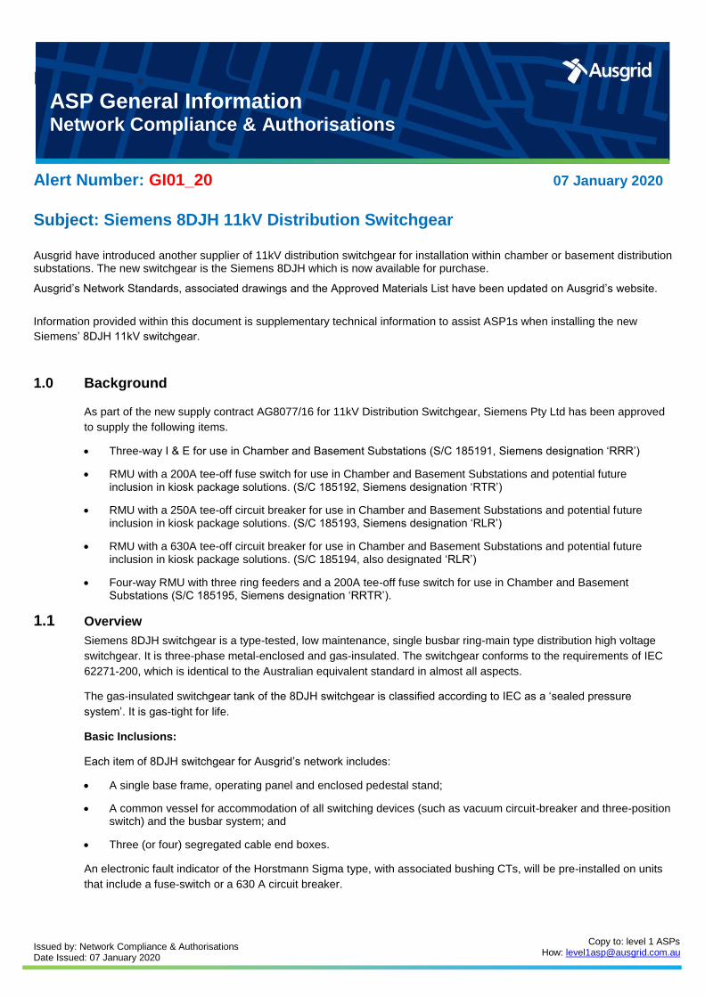
Figure 1 – 8DJH ‘RRR’ unit.
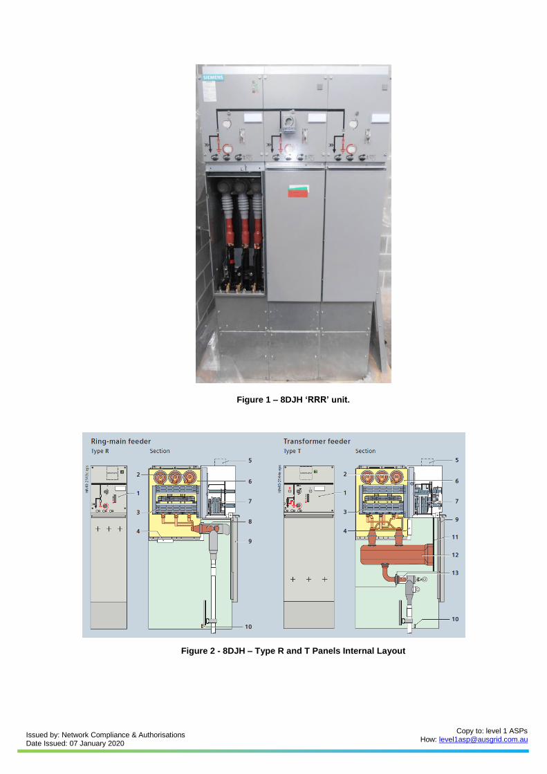
Figure 2 - 8DJH – Type R and T Panels Internal Layout
Issued by: Network Compliance & Authorisations Date Issued: 07 January 2020
Copy to: level 1 ASPs How: [email protected]
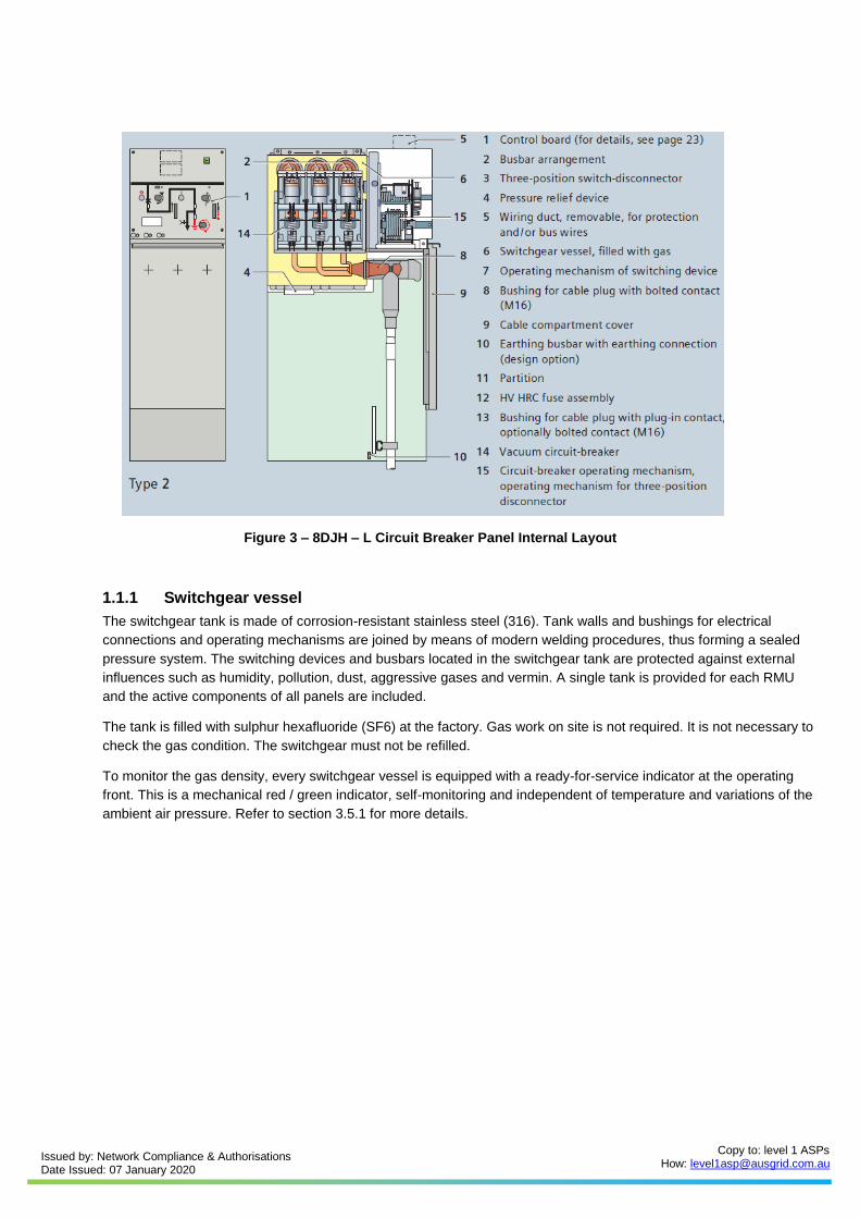
Figure 3 – 8DJH – L Circuit Breaker Panel Internal Layout
1.1.1 Switchgear vessel
The switchgear tank is made of corrosion-resistant stainless steel (316). Tank walls and bushings for electrical
connections and operating mechanisms are joined by means of modern welding procedures, thus forming a sealed
pressure system. The switching devices and busbars located in the switchgear tank are protected against external
influences such as humidity, pollution, dust, aggressive gases and vermin. A single tank is provided for each RMU
and the active components of all panels are included.
The tank is filled with sulphur hexafluoride (SF6) at the factory. Gas work on site is not required. It is not necessary to
check the gas condition. The switchgear must not be refilled.
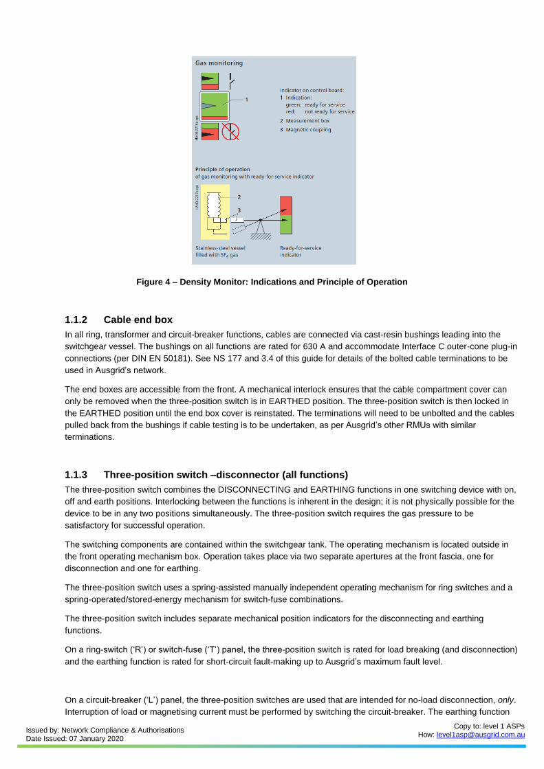
To monitor the gas density, every switchgear vessel is equipped with a ready-for-service indicator at the operating
front. This is a mechanical red / green indicator, self-monitoring and independent of temperature and variations of the
ambient air pressure. Refer to section 3.5.1 for more details.
Issued by: Network Compliance & Authorisations Date Issued: 07 January 2020
Copy to: level 1 ASPs How: [email protected]
Figure 4 – Density Monitor: Indications and Principle of Operation
1.1.2 Cable end box
In all ring, transformer and circuit-breaker functions, cables are connected via cast-resin bushings leading into the
switchgear vessel. The bushings on all functions are rated for 630 A and accommodate Interface C outer-cone plug-in
connections (per DIN EN 50181). See NS 177 and 3.4 of this guide for details of the bolted cable terminations to be
used in Ausgrid’s network.
The end boxes are accessible from the front. A mechanical interlock ensures that the cable compartment cover can
only be removed when the three-position switch is in EARTHED position. The three-position switch is then locked in
the EARTHED position until the end box cover is reinstated. The terminations will need to be unbolted and the cables
pulled back from the bushings if cable testing is to be undertaken, as per Ausgrid’s other RMUs with similar
terminations.
1.1.3 Three-position switch –disconnector (all functions)
The three-position switch combines the DISCONNECTING and EARTHING functions in one switching device with on,
off and earth positions. Interlocking between the functions is inherent in the design; it is not physically possible for the
device to be in any two positions simultaneously. The three-position switch requires the gas pressure to be
satisfactory for successful operation.
The switching components are contained within the switchgear tank. The operating mechanism is located outside in
the front operating mechanism box. Operation takes place via two separate apertures at the front fascia, one for
disconnection and one for earthing.
The three-position switch uses a spring-assisted manually independent operating mechanism for ring switches and a
spring-operated/stored-energy mechanism for switch-fuse combinations.
The three-position switch includes separate mechanical position indicators for the disconnecting and earthing
functions.
On a ring-switch (‘R’) or switch-fuse (‘T’) panel, the three-position switch is rated for load breaking (and disconnection)
and the earthing function is rated for short-circuit fault-making up to Ausgrid’s maximum fault level.
On a circuit-breaker (‘L’) panel, the three-position switches are used that are intended for no-load disconnection, only.
Interruption of load or magnetising current must be performed by switching the circuit-breaker. The earthing function
Issued by: Network Compliance & Authorisations Date Issued: 07 January 2020
Copy to: level 1 ASPs How: [email protected]
of the three-position switch is fully rated for fault-making.
The three-position switch can be locked in its current position, or prevented from entering a particular position, by
padlocking the control gate.
1.1.4 Circuit breaker (L Function)
The circuit-breakers of 8DJH switchgear operate based on vacuum switching technology. The vacuum interrupter unit
is installed in the switchgear tank together with the accompanying three-position switch. The operating mechanisms of
the circuit-breaker are located outside the switchgear tank. Both the interrupters and the operating mechanisms are
maintenance-free under normal conditions.
The circuit breaker has a trip-free, stored-energy spring-operated mechanism. The act of charging the closing spring
manually (or by a spring-charging motor, as optionally fitted) is independent of the act of closing the circuit breaker;
the circuit breaker can be left in a spring-charged and ready-to-close state indefinitely.
The circuit breaker’s position and the state of spring are shown by mechanical indicators on the front panel.
Mechanical close and open pushbuttons are provided, along with trip coil(s) for protection tripping. Electrical spring
charging and a spring-release coil for electronic closing are fitted to S/C 185194 only.
The circuit breaker found in Ausgrid’s applications is called a ‘Type 2’ Vacuum Circuit Breaker (VCB) by Siemens. The
Type 2 circuit breaker is not suitable for reclosing.
Access to the spring-charging device can be prevented using a padlock.
A circuit breaker ‘L’ panel contains the circuit breaker itself for disconnection and a downstream three-position switch
for isolation and earthing.
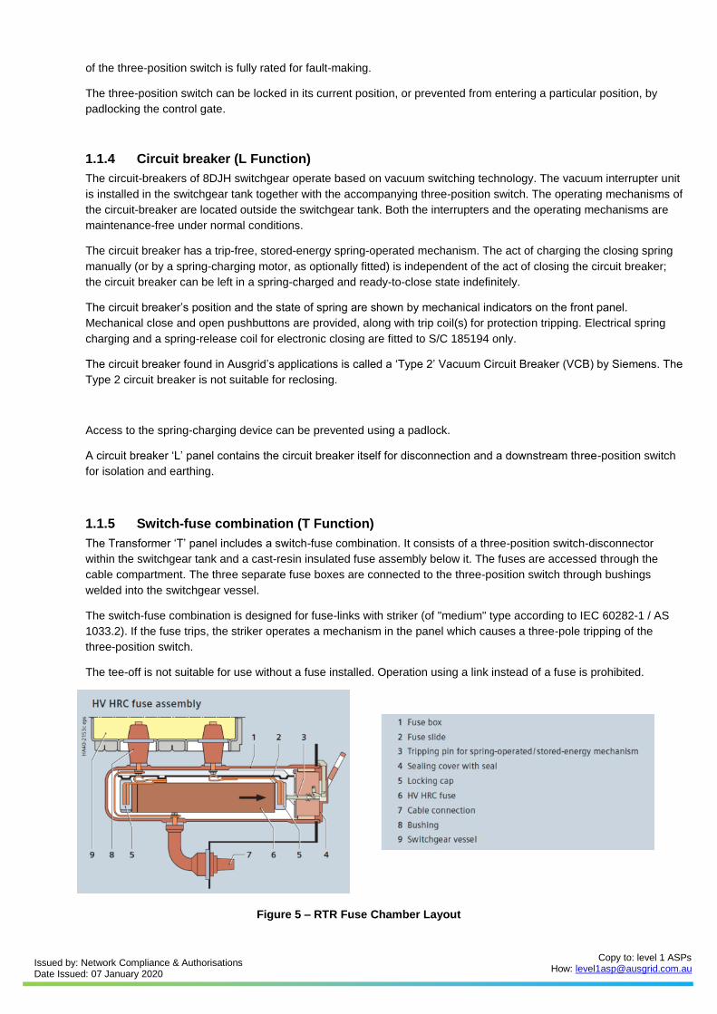
1.1.5 Switch-fuse combination (T Function)
The Transformer ‘T’ panel includes a switch-fuse combination. It consists of a three-position switch-disconnector
within the switchgear tank and a cast-resin insulated fuse assembly below it. The fuses are accessed through the
cable compartment. The three separate fuse boxes are connected to the three-position switch through bushings
welded into the switchgear vessel.
The switch-fuse combination is designed for fuse-links with striker (of "medium" type according to IEC 60282-1 / AS
1033.2). If the fuse trips, the striker operates a mechanism in the panel which causes a three-pole tripping of the
three-position switch.
The tee-off is not suitable for use without a fuse installed. Operation using a link instead of a fuse is prohibited.
Figure 5 – RTR Fuse Chamber Layout
Issued by: Network Compliance & Authorisations Date Issued: 07 January 2020
Copy to: level 1 ASPs How: [email protected]
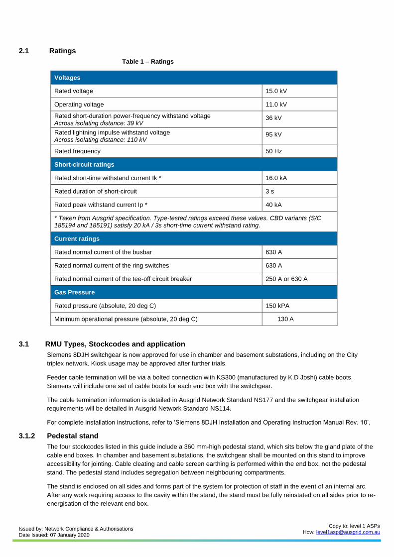
2.1 Ratings
Table 1 – Ratings
Voltages
Rated voltage 15.0 kV
Operating voltage 11.0 kV
Rated short-duration power-frequency withstand voltage Across isolating distance: 39 kV
36 kV
Rated lightning impulse withstand voltage Across isolating distance: 110 kV
95 kV
Rated frequency 50 Hz
Short-circuit ratings
Rated short-time withstand current Ik * 16.0 kA
Rated duration of short-circuit 3 s
Rated peak withstand current Ip * 40 kA
* Taken from Ausgrid specification. Type-tested ratings exceed these values. CBD variants (S/C 185194 and 185191) satisfy 20 kA / 3s short-time current withstand rating.
Current ratings
Rated normal current of the busbar 630 A
Rated normal current of the ring switches 630 A
Rated normal current of the tee-off circuit breaker 250 A or 630 A
Gas Pressure
Rated pressure (absolute, 20 deg C) 150 kPA
Minimum operational pressure (absolute, 20 deg C) 130 A
3.1 RMU Types, Stockcodes and application
Siemens 8DJH switchgear is now approved for use in chamber and basement substations, including on the City
triplex network. Kiosk usage may be approved after further trials.
Feeder cable termination will be via a bolted connection with KS300 (manufactured by K.D Joshi) cable boots.
Siemens will include one set of cable boots for each end box with the switchgear.
The cable termination information is detailed in Ausgrid Network Standard NS177 and the switchgear installation
requirements will be detailed in Ausgrid Network Standard NS114.
For complete installation instructions, refer to ‘Siemens 8DJH Installation and Operating Instruction Manual Rev. 10’,
3.1.2 Pedestal stand
The four stockcodes listed in this guide include a 360 mm-high pedestal stand, which sits below the gland plate of the
cable end boxes. In chamber and basement substations, the switchgear shall be mounted on this stand to improve
accessibility for jointing. Cable cleating and cable screen earthing is performed within the end box, not the pedestal
stand. The pedestal stand includes segregation between neighbouring compartments.
The stand is enclosed on all sides and forms part of the system for protection of staff in the event of an internal arc.
After any work requiring access to the cavity within the stand, the stand must be fully reinstated on all sides prior to re-
energisation of the relevant end box.
Issued by: Network Compliance & Authorisations Date Issued: 07 January 2020
Copy to: level 1 ASPs How: [email protected]
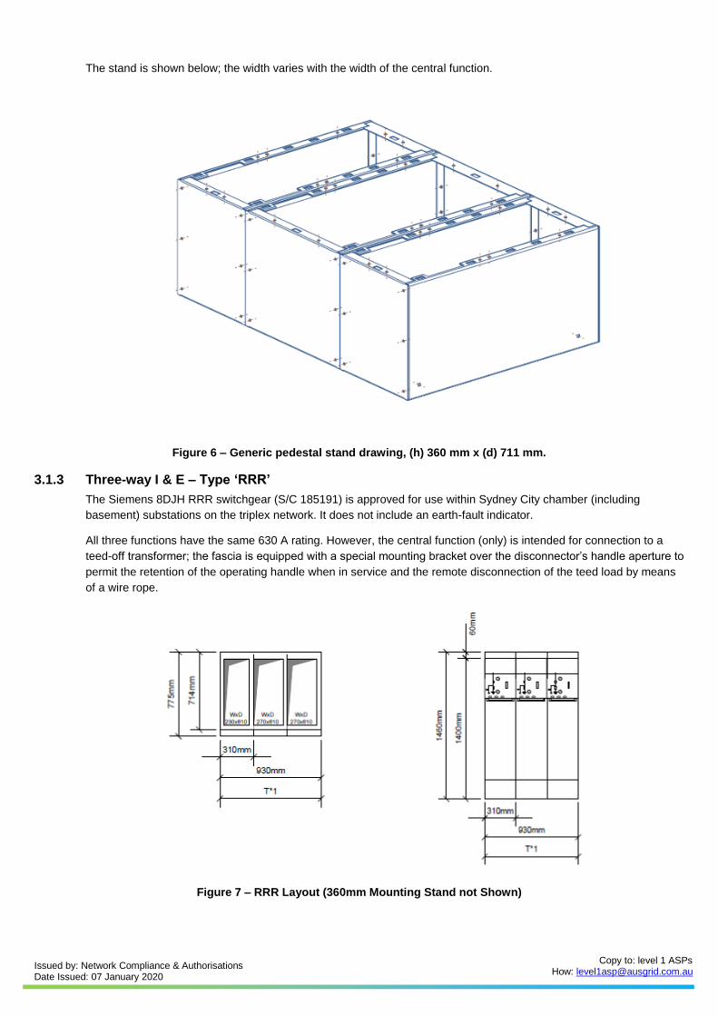
The stand is shown below; the width varies with the width of the central function.
Figure 6 – Generic pedestal stand drawing, (h) 360 mm x (d) 711 mm.
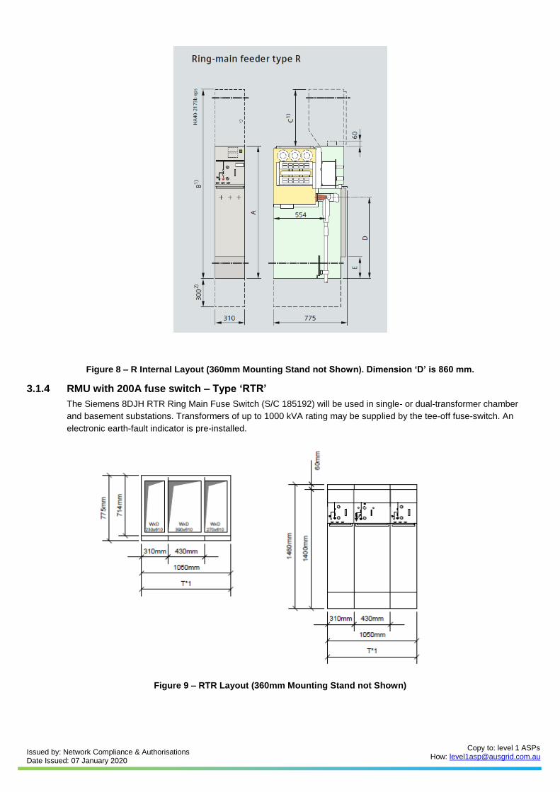
3.1.3 Three-way I & E – Type ‘RRR’
The Siemens 8DJH RRR switchgear (S/C 185191) is approved for use within Sydney City chamber (including
basement) substations on the triplex network. It does not include an earth-fault indicator.
All three functions have the same 630 A rating. However, the central function (only) is intended for connection to a
teed-off transformer; the fascia is equipped with a special mounting bracket over the disconnector’s handle aperture to
permit the retention of the operating handle when in service and the remote disconnection of the teed load by means
of a wire rope.
Figure 7 – RRR Layout (360mm Mounting Stand not Shown)
Issued by: Network Compliance & Authorisations Date Issued: 07 January 2020
Copy to: level 1 ASPs How: [email protected]
Figure 8 – R Internal Layout (360mm Mounting Stand not Shown). Dimension ‘D’ is 860 mm.
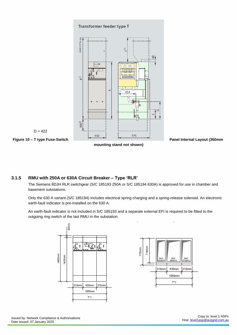
3.1.4 RMU with 200A fuse switch – Type ‘RTR’
The Siemens 8DJH RTR Ring Main Fuse Switch (S/C 185192) will be used in single- or dual-transformer chamber
and basement substations. Transformers of up to 1000 kVA rating may be supplied by the tee-off fuse-switch. An
electronic earth-fault indicator is pre-installed.
Figure 9 – RTR Layout (360mm Mounting Stand not Shown)
Issued by: Network Compliance & Authorisations Date Issued: 07 January 2020
Copy to: level 1 ASPs How: [email protected]
D = 422
Figure 10 – T type Fuse-Switch Panel Internal Layout (360mm
mounting stand not shown)
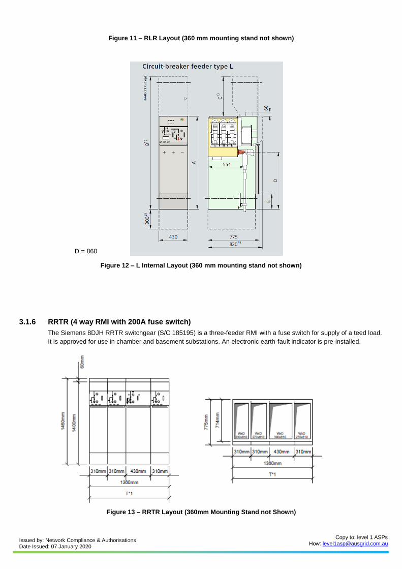
3.1.5 RMU with 250A or 630A Circuit Breaker – Type ‘RLR’
The Siemens 8DJH RLR switchgear (S/C 185193 250A or S/C 185194 630A) is approved for use in chamber and
basement substations.
Only the 630 A variant (S/C 185194) includes electrical spring charging and a spring-release solenoid. An electronic
earth-fault indicator is pre-installed on the 630 A.
An earth-fault indicator is not included in S/C 185193 and a separate external EFI is required to be fitted to the
outgoing ring switch of the last RMU in the substation.
Issued by: Network Compliance & Authorisations Date Issued: 07 January 2020
Copy to: level 1 ASPs How: [email protected]
Figure 11 – RLR Layout (360 mm mounting stand not shown)
D = 860
Figure 12 – L Internal Layout (360 mm mounting stand not shown)
3.1.6 RRTR (4 way RMI with 200A fuse switch)
The Siemens 8DJH RRTR switchgear (S/C 185195) is a three-feeder RMI with a fuse switch for supply of a teed load.
It is approved for use in chamber and basement substations. An electronic earth-fault indicator is pre-installed.
Figure 13 – RRTR Layout (360mm Mounting Stand not Shown)
Issued by: Network Compliance & Authorisations Date Issued: 07 January 2020
Copy to: level 1 ASPs How: [email protected]
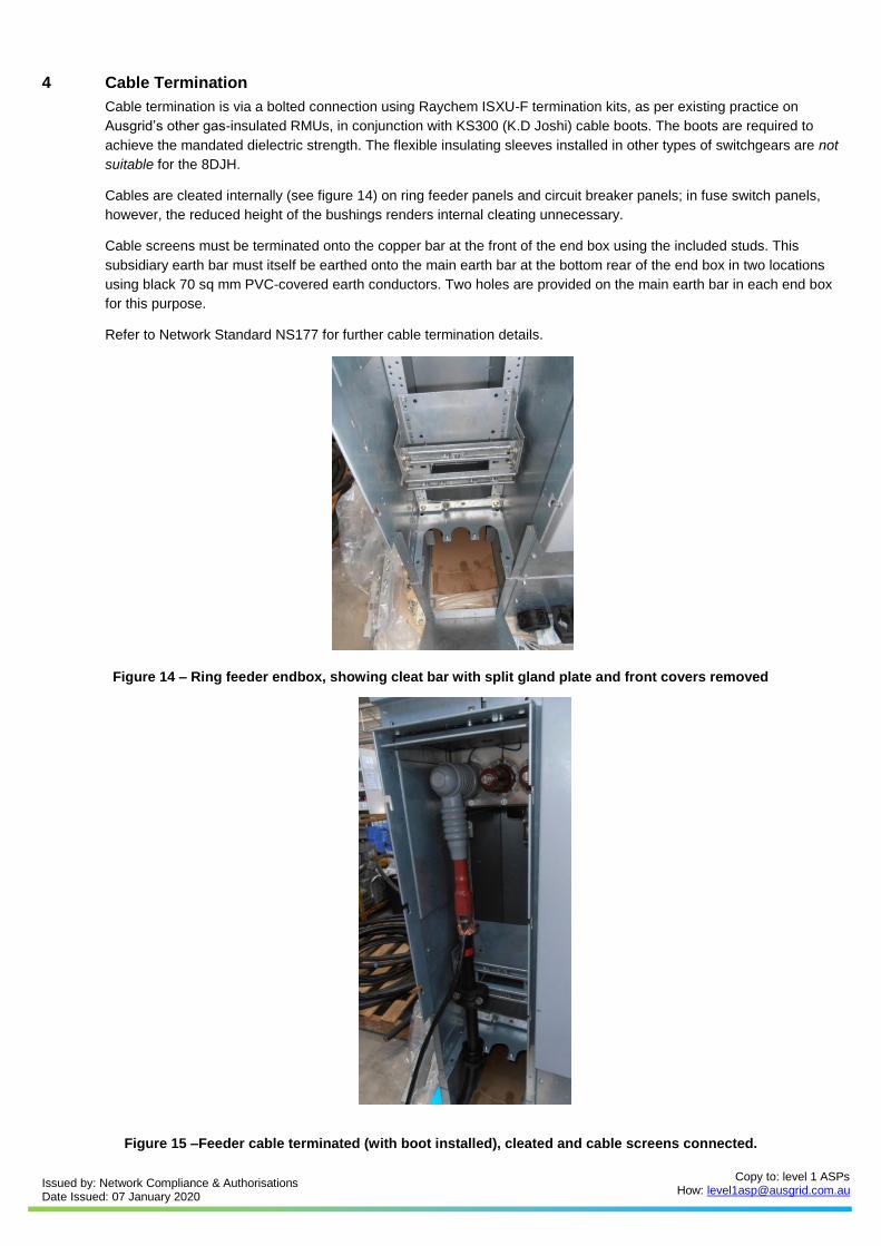
4 Cable Termination
Cable termination is via a bolted connection using Raychem ISXU-F termination kits, as per existing practice on
Ausgrid’s other gas-insulated RMUs, in conjunction with KS300 (K.D Joshi) cable boots. The boots are required to
achieve the mandated dielectric strength. The flexible insulating sleeves installed in other types of switchgears are not
suitable for the 8DJH.
Cables are cleated internally (see figure 14) on ring feeder panels and circuit breaker panels; in fuse switch panels,
however, the reduced height of the bushings renders internal cleating unnecessary.
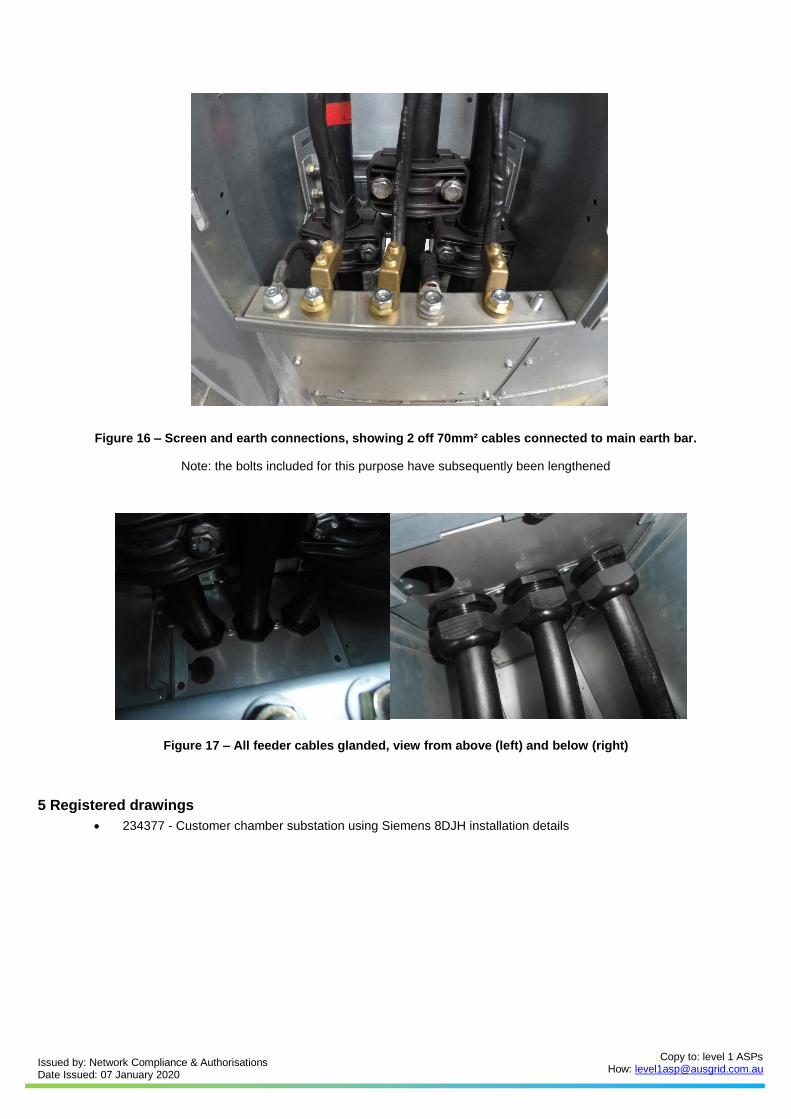
Cable screens must be terminated onto the copper bar at the front of the end box using the included studs. This
subsidiary earth bar must itself be earthed onto the main earth bar at the bottom rear of the end box in two locations
using black 70 sq mm PVC-covered earth conductors. Two holes are provided on the main earth bar in each end box
for this purpose.
Refer to Network Standard NS177 for further cable termination details.
Figure 14 – Ring feeder endbox, showing cleat bar with split gland plate and front covers removed
Figure 15 –Feeder cable terminated (with boot installed), cleated and cable screens connected.
Issued by: Network Compliance & Authorisations Date Issued: 07 January 2020
Copy to: level 1 ASPs How: [email protected]
Figure 16 – Screen and earth connections, showing 2 off 70mm² cables connected to main earth bar.
Note: the bolts included for this purpose have subsequently been lengthened
Figure 17 – All feeder cables glanded, view from above (left) and below (right)
5 Registered drawings
• 234377 - Customer chamber substation using Siemens 8DJH installation details
Issued by: Network Compliance & Authorisations Date Issued: 07 January 2020
Copy to: level 1 ASPs How: [email protected]
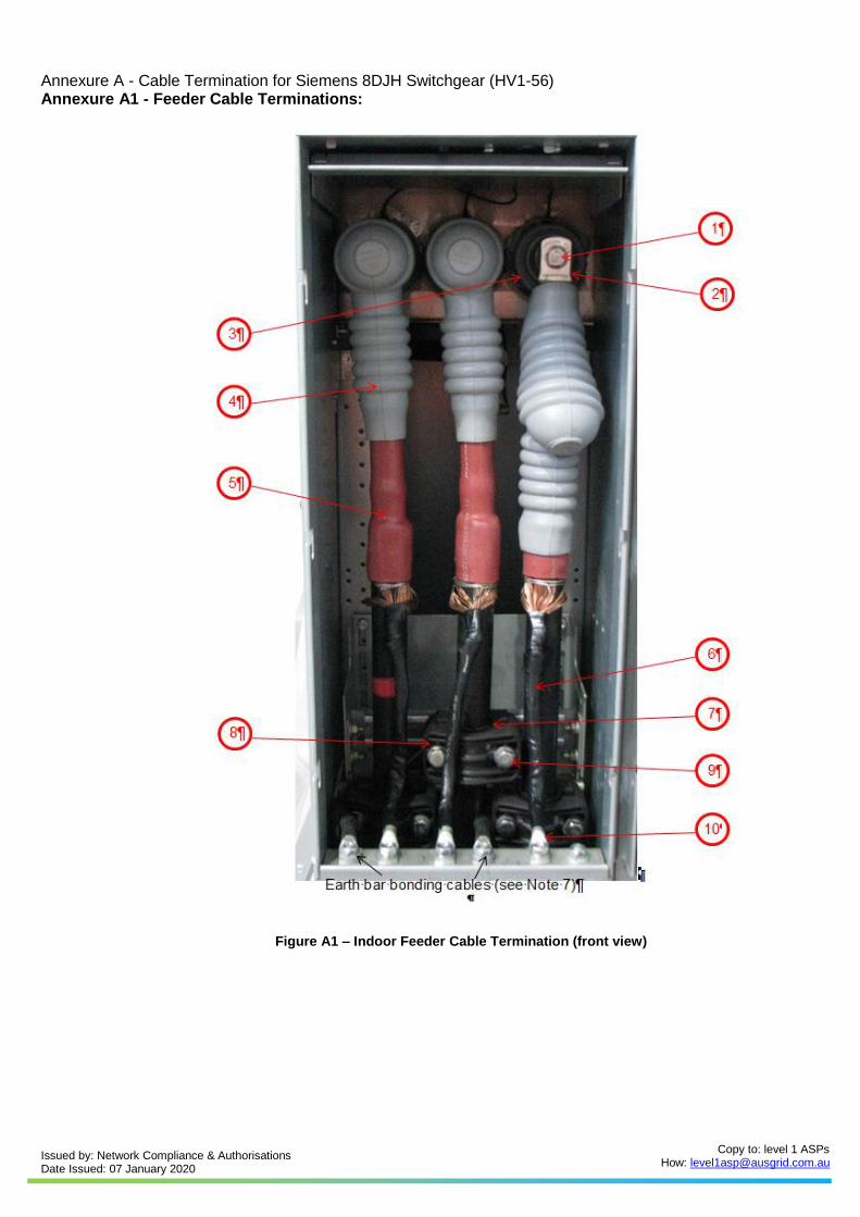
Annexure A - Cable Termination for Siemens 8DJH Switchgear (HV1-56) Annexure A1 - Feeder Cable Terminations:
Figure A1 – Indoor Feeder Cable Termination (front view)
Issued by: Network Compliance & Authorisations Date Issued: 07 January 2020
Copy to: level 1 ASPs How: [email protected]
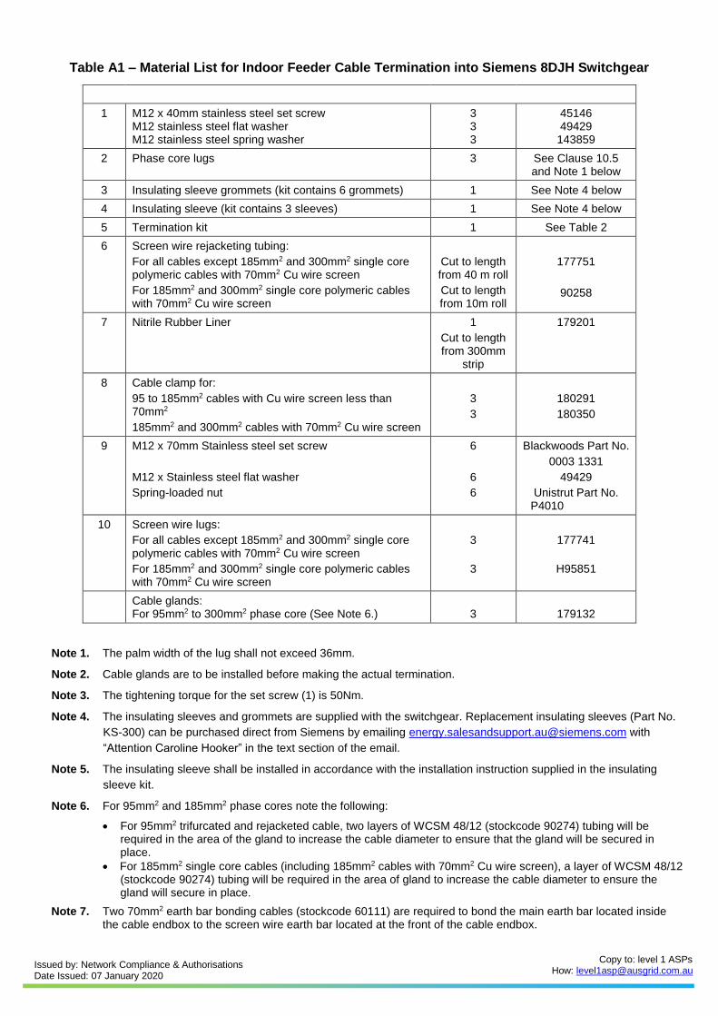
Table A1 – Material List for Indoor Feeder Cable Termination into Siemens 8DJH Switchgear
Item Description Qty Stockcode
1 M12 x 40mm stainless steel set screw M12 stainless steel flat washer M12 stainless steel spring washer
3 3 3
45146 49429
143859
2 Phase core lugs 3 See Clause 10.5 and Note 1 below
3 Insulating sleeve grommets (kit contains 6 grommets) 1 See Note 4 below
4 Insulating sleeve (kit contains 3 sleeves) 1 See Note 4 below
5 Termination kit 1 See Table 2
6 Screen wire rejacketing tubing:
For all cables except 185mm2 and 300mm2 single core polymeric cables with 70mm2 Cu wire screen
For 185mm2 and 300mm2 single core polymeric cables with 70mm2 Cu wire screen
Cut to length from 40 m roll
Cut to length from 10m roll
177751
90258
7 Nitrile Rubber Liner 1
Cut to length from 300mm
strip
179201
8 Cable clamp for:
95 to 185mm2 cables with Cu wire screen less than 70mm2
185mm2 and 300mm2 cables with 70mm2 Cu wire screen
3
3
180291
180350
9 M12 x 70mm Stainless steel set screw
M12 x Stainless steel flat washer
Spring-loaded nut
6
6
6
Blackwoods Part No.
0003 1331
49429
Unistrut Part No. P4010
10 Screen wire lugs:
For all cables except 185mm2 and 300mm2 single core polymeric cables with 70mm2 Cu wire screen
For 185mm2 and 300mm2 single core polymeric cables with 70mm2 Cu wire screen
3
3
177741
H95851
Cable glands: For 95mm2 to 300mm2 phase core (See Note 6.)
3
179132
Note 1. The palm width of the lug shall not exceed 36mm.
Note 2. Cable glands are to be installed before making the actual termination.
Note 3. The tightening torque for the set screw (1) is 50Nm.
Note 4. The insulating sleeves and grommets are supplied with the switchgear. Replacement insulating sleeves (Part No.
KS-300) can be purchased direct from Siemens by emailing [email protected] with
“Attention Caroline Hooker” in the text section of the email.
Note 5. The insulating sleeve shall be installed in accordance with the installation instruction supplied in the insulating
sleeve kit.
Note 6. For 95mm2 and 185mm2 phase cores note the following:
• For 95mm2 trifurcated and rejacketed cable, two layers of WCSM 48/12 (stockcode 90274) tubing will be required in the area of the gland to increase the cable diameter to ensure that the gland will be secured in place.
• For 185mm2 single core cables (including 185mm2 cables with 70mm2 Cu wire screen), a layer of WCSM 48/12 (stockcode 90274) tubing will be required in the area of gland to increase the cable diameter to ensure the gland will secure in place.
Note 7. Two 70mm2 earth bar bonding cables (stockcode 60111) are required to bond the main earth bar located inside the cable endbox to the screen wire earth bar located at the front of the cable endbox.
Issued by: Network Compliance & Authorisations Date Issued: 07 January 2020
Copy to: level 1 ASPs How: [email protected]
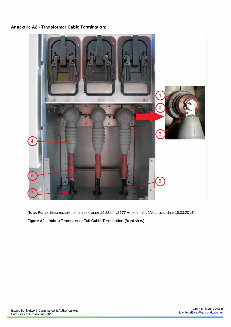
Annexure A2 - Transformer Cable Termination:
Note: For earthing requirements see clause 10.22 of NS177 Amendment 1(Approval date 15.03.2018).
Figure A2 – Indoor Transformer Tail Cable Termination (front view)
Issued by: Network Compliance & Authorisations Date Issued: 07 January 2020
Copy to: level 1 ASPs How: [email protected]
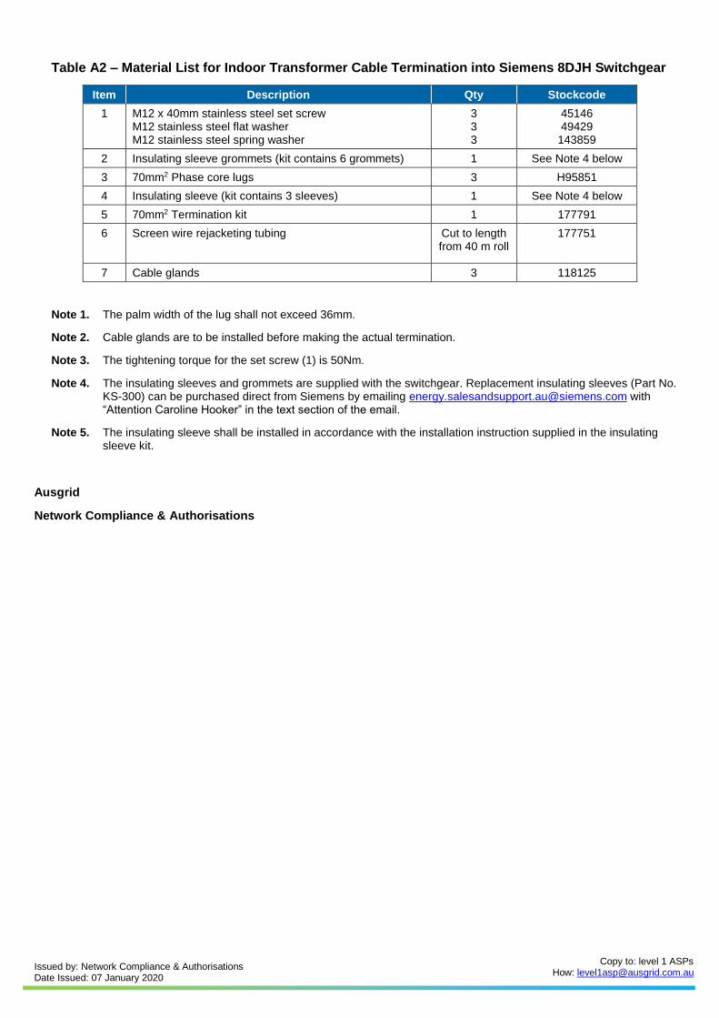
Table A2 – Material List for Indoor Transformer Cable Termination into Siemens 8DJH Switchgear
Item Description Qty Stockcode
1 M12 x 40mm stainless steel set screw M12 stainless steel flat washer M12 stainless steel spring washer
3 3 3
45146 49429
143859
2 Insulating sleeve grommets (kit contains 6 grommets) 1 See Note 4 below
3 70mm2 Phase core lugs 3 H95851
4 Insulating sleeve (kit contains 3 sleeves) 1 See Note 4 below
5 70mm2 Termination kit 1 177791
6 Screen wire rejacketing tubing Cut to length from 40 m roll
177751
7 Cable glands 3 118125
Note 1. The palm width of the lug shall not exceed 36mm.
Note 2. Cable glands are to be installed before making the actual termination.
Note 3. The tightening torque for the set screw (1) is 50Nm.
Note 4. The insulating sleeves and grommets are supplied with the switchgear. Replacement insulating sleeves (Part No. KS-300) can be purchased direct from Siemens by emailing [email protected] with “Attention Caroline Hooker” in the text section of the email.
Note 5. The insulating sleeve shall be installed in accordance with the installation instruction supplied in the insulating sleeve kit.
Ausgrid
Network Compliance & Authorisations


![National Environmental Management: Integrated Coastal Management Amendment Bill [B8F-2013] PORTFOLIO COMMITTEE 29 JULY 2014 Legal Authorisations Compliance](https://img.pdfslide.us/doc/110x75/56649d6f5503460f94a50d85/national-environmental-management-integrated-coastal-management-amendment.jpg)