Embed Size (px)
Citation preview

Title:
Licensee:
Date:
Conditions of use (Click here for full conditions of Licence)
WWWWEB EB EB EB SSSSEARCHEARCHEARCHEARCHCheck if current
StandardsWatch (Info and Login)
Find similar documents
Visit our website
Standards AustraliaLICENCE
AS/NZS 4268:2003
Australian/New Zealand Standard™
Radio equipment and systems—Short range devices—Limits and methods of measurement
AS
/NZ
S 4
268
Lice
nsed
to S
PA
RA
MA
NA
NT
HA
N o
n 14
Apr
200
4. 1
use
r pe
rson
al u
ser
licen
ce o
nly.
Sto
rage
, dis
trib
utio
n or
use
on
netw
ork
proh
ibite
d.
AS/NZS 4268:2003
This Joint Australian/New Zealand Standard was prepared by Joint Technical Committee RC-006, Radiocommunications Equipment—General. It was approved on behalf of the Council of Standards Australia on 29 September 2003 and on behalf of the Council of Standards New Zealand on 30 September 2003. It was published on 29 December 2003.
The following are represented on Committee RC-006:
Australian Communications Authority Australian Electrical and Electronic Manufacturers Association Civil Aviation Safety Authority Department of Defence, Australia Electromagnetic Compatibility Society of Australia Electromagnetic Technical Evaluation Committee Ministry of Economic Development, New Zealand SingTel Optus Telstra Corporation
Keeping Standards up-to-date
Standards are living documents which reflect progress in science, technology and systems. To maintain their currency, all Standards are periodically reviewed, and new editions are published. Between editions, amendments may be issued. Standards may also be withdrawn. It is important that readers assure themselves they are using a current Standard, which should include any amendments which may have been published since the Standard was purchased.
Detailed information about joint Australian/New Zealand Standards can be found by visiting the Standards Australia web site at www.standards.com.au or Standards New Zealand web site at www.standards.co.nz and looking up the relevant Standard in the on-line catalogue.
Alternatively, both organizations publish an annual printed Catalogue with full details of all current Standards. For more frequent listings or notification of revisions, amendments and withdrawals, Standards Australia and Standards New Zealand offer a number of update options. For information about these services, users should contact their respective national Standards organization.
We also welcome suggestions for improvement in our Standards, and especially encourage readers to notify us immediately of any apparent inaccuracies or ambiguities. Please address your comments to the Chief Executive of either Standards Australia International or Standards New Zealand at the address shown on the back cover.
This Standard was issued in draft form for comment as DR 03333.Lice
nsed
to S
PA
RA
MA
NA
NT
HA
N o
n 14
Apr
200
4. 1
use
r pe
rson
al u
ser
licen
ce o
nly.
Sto
rage
, dis
trib
utio
n or
use
on
netw
ork
proh
ibite
d.
AS/NZS 4268:2003
Australian/New Zealand Standard™
Radio equipment and systems—Short range devices—Limits and methods of measurement
Originated as AS 4268.1—1996 and AS 4268.2—1995. Jointly revised, amalgamated and redesignated as AS/NZS 4268:2003.
COPYRIGHT
© Standards Australia/Standards New Zealand
All rights are reserved. No part of this work may be reproduced or copied in any form or by any means, electronic or mechanical, including photocopying, without the written permission of the publisher.
Jointly published by Standards Australia International Ltd, GPO Box 5420, Sydney, NSW 2001 and Standards New Zealand, Private Bag 2439, Wellington 6020
ISBN 0 7337 5540 2
Lice
nsed
to S
PA
RA
MA
NA
NT
HA
N o
n 14
Apr
200
4. 1
use
r pe
rson
al u
ser
licen
ce o
nly.
Sto
rage
, dis
trib
utio
n or
use
on
netw
ork
proh
ibite
d.
AS/NZS 4268:2003 2
PREFACE
This Standard was prepared by the Joint Standards Australia/Standards New Zealand
Committee RC-006, Radiocommunications Equipment—General to supersede
AS 4268.1—1996 and AS 4268.2—1995.
The objective of this Standard is to provide limits and methods of measurement for short
range devices placed on the Australian market, and authorized for use by the
Radiocommunications (Low Interference Potential Devices) Class Licence 2000 (LIPD) and
Radiocommunications (Radio-controlled Models) Class Licence 2002 Class Licences issued
by the Australian Communications Authority, or short range devices placed on the New
Zealand market, and authorized for use by the General User Radio Licence (GURL) issued
by the New Zealand Ministry of Economic Development.
Lice
nsed
to S
PA
RA
MA
NA
NT
HA
N o
n 14
Apr
200
4. 1
use
r pe
rson
al u
ser
licen
ce o
nly.
Sto
rage
, dis
trib
utio
n or
use
on
netw
ork
proh
ibite
d.
3 AS/NZS 4268:2003
CONTENTS
Page
1 SCOPE......................................................................................................................... 4
2 REFERENCED DOCUMENTS................................................................................... 4
3 DEFINITIONS............................................................................................................. 5
4 TEST CONDITIONS................................................................................................... 6
5 RADIATED MEASUREMENTS ................................................................................ 9
6 INTERPRETATION OF TEST RESULTS AGAINST LIMITS TO DETERMINE
COMPLIANCE.......................................................................................................... 10
7 FREQUENCY BANDS ............................................................................................. 11
8 TRANSMITTER PARAMETERS............................................................................. 11
9 RECEIVER PARAMETERS ..................................................................................... 14
10 FURTHER INFORMATION..................................................................................... 26
Lice
nsed
to S
PA
RA
MA
NA
NT
HA
N o
n 14
Apr
200
4. 1
use
r pe
rson
al u
ser
licen
ce o
nly.
Sto
rage
, dis
trib
utio
n or
use
on
netw
ork
proh
ibite
d.
AS/NZS 4268:2003 4
COPYRIGHT
STANDARDS AUSTRALIA/STANDARDS NEW ZEALAND
Australian/New Zealand Standard
Radio equipment and systems—Short range devices—Limits and methods of measurement
1 SCOPE
This Standard applies to Short Range Devices (SRDs) commonly used for
radiocommunication in Australia and New Zealand. Examples of SRDs are: alarms, baby
monitors, garage door openers, data collection systems, retail and logistic systems,
telecommand applications, wireless home data telemetry and/or security systems, and
keyless automobile entry systems. SRDs use all types of modulation, may be fixed, mobile
or portable and have dedicated, and/or integral antennas.
In Australia and New Zealand, SRDs may be referred to as Low Interference Potential
Devices (LIPDs). In New Zealand, before 2002, SRDs were known as Restricted Radiation
Devices (RRDs).
This Standard specifies the minimum performance and methods of measurement for Short
Range Devices whose use is supported by the following Radiocommunications Licences:
(a) Australia The Radiocommunications (Low Interference Potential Devices) Class
Licence 2000 and the Radiocommunications (Radio-controlled Models) Class Licence
2002. Other requirements also exist under the Radiocommunications Compliance and
Labelling scheme.
(b) New Zealand The Radiocommunications Regulations (General User Radio Licence
for Short Range Devices) Notice hereafter referred to as the General User Radio
Licence or GURL.
SRDs can be expected to be sharing radiofrequency spectrum with other
radiocommunications devices. It is a condition of operation of an SRD that the device not
cause interference to other radiocommunications devices. If an SRD causes harmful
interference to authorized radiocommunications devices, even if the SRD complies with all
of the technical Standards and equipment authorization requirements in the National rules,
the user of that device is in breach of the conditions of operation of that device. As well,
SRDs are not afforded protection from interference caused by other radiocommunications
services.
2 REFERENCED DOCUMENTS
The following documents are referred to in this Standard:
AS/NZS
CISPR 11 Industrial, scientific and medical (ISM) radio-frequency equipment—
Electromagnetic disturbance characteristics—Limits and methods of
measurement
CISPR 16 CISPR specification for radio disturbance and immunity measuring
apparatus and methods
CISPR 16.1 Part 1: Radio disturbance and immunity measuring apparatus
CISPR 22 Information technology equipment—Radio disturbance characteristics—
Limits and methods of measurement
Lice
nsed
to S
PA
RA
MA
NA
NT
HA
N o
n 14
Apr
200
4. 1
use
r pe
rson
al u
ser
licen
ce o
nly.
Sto
rage
, dis
trib
utio
n or
use
on
netw
ork
proh
ibite
d.
5 AS/NZS 4268:2003
COPYRIGHT
ANSI
C63.4 American National Standard for Methods of Measurement of Radio-
Noise Emissions from Low-Voltage Electrical and Electronic Equipment
in the Range of 9 kHz to 40 GHz
ETSI
EN 300 220 ElectroMagnetic Compatibility and Radio Spectrum Matters (ERM);
Short Range Devices (SRD); Radio equipment to be used in the 25 MHz
to 1 000 MHz frequency range with power levels ranging up to 500 mW
EN 300 220-1 Part 1: Technical characteristics and test methods
EN 300 330 ElectroMagnetic Compatibility and Radio Spectrum Matters (ERM);
Short Range Devices (SRD); Radio equipment in the frequency range 9
kHz to 25 MHz and inductive loop systems in the frequency range 9 kHz
to 30 MHz
EN 300 330-1
V1.3.2
Part 1: Technical characteristics and test methods
EN 300 440 Electromagnetic Compatibility and Radio spectrum Matters (ERM);
Short range devices; Radio equipment to be used in the 1 GHz to 40 GHz
frequency range
EN 300 440-1
V1.3.1
Part 1: Technical characteristics and test methods
ETR 273 Electromagnetic Compatibility and Radio spectrum Matters (ERM);
Improvement of radiated methods of measurement (using test sites) and
evaluation of the corresponding measurement uncertainties
ETR 273-1-1 Part 1: Uncertainties in the measurement of mobile radio equipment
characteristics; Sub-part 1: Introduction
Australian
Communications
Authority
Radiocommunications (Low Interference Potential Devices) Class
Licence 2000
Radiocommunications (Radio-controlled Models) Class Licence 2002
New Zealand
Ministry for
Economic
development
Radiocommunications Regulations (General User Radio Licence for
Short Range Devices) Notice
3 DEFINITIONS
For the purpose of this Standard, the following definitions apply.
3.1 Alarm
Use of radiocommunication for indicating an alarm condition at a distant location.
3.2 Dedicated antenna
Removable antenna supplied and type tested with the radio equipment, designed as an
indispensable part of the equipment.
3.3 Digital modulation transmitter
A digital modulation transmitter is an intentional radiator (device) that may use digital
modulation techniques such as direct sequence spread spectrum modulation, or other forms
of complex digital modulation such as coded orthogonal frequency division multiplexing.
Lice
nsed
to S
PA
RA
MA
NA
NT
HA
N o
n 14
Apr
200
4. 1
use
r pe
rson
al u
ser
licen
ce o
nly.
Sto
rage
, dis
trib
utio
n or
use
on
netw
ork
proh
ibite
d.
AS/NZS 4268:2003 6
COPYRIGHT
3.4 Effective radiated power (ERP)
The product of the power supplied to the antenna and its gain relative to a half wave dipole
in a given direction (normally the direction of maximum radiation).
3.5 Emission bandwidth
The width of a frequency band such that, below the lower and above the upper frequency
limits, the mean powers emitted are each equal to 0.5% of the total mean power of a given
emission.
3.6 Equivalent isotropically radiated power (EIRP)
The product of the power supplied to the antenna and its gain in a given direction (normally
the direction of maximum radiation) relative to an isotropic antenna (absolute or isotropic
gain).
NOTE: ERP will always be 2.15 dB less than EIRP for the same radiator in a given direction.
3.7 Far field
Region where the electric and magnetic fields exist as closed loops independently of the
source antenna. The far field begins approximately where the power density begins to
decrease in proportion to the inverse square of the distance to the antenna.
NOTE: For a dipole antenna this corresponds to a distance greater than λ/2π metres, (where λ is
wavelength).
3.8 Fixed station
Equipment intended for use in a fixed location.
3.9 Integral antenna
Permanent fixed antenna, which may be built in, designed as an indispensable part of the
equipment.
3.10 Mobile station
Equipment normally fixed in a vehicle.
3.11 Portable station
Equipment intended to be carried, attached or implanted.
3.12 Radiated measurements
Measurements that involve the measurement of a radiated field.
3.13 Telecommand
Use of radiocommunication for the transmission of signals to initiate, modify or terminate
functions of equipment at a distance.
3.14 Telemetry
Use of radiocommunication for indicating or recording data at a distance.
4 TEST CONDITIONS
Where doubt exists with regard to test conditions or any test parameter, the National
Regulator is to be consulted.
4.1 Number of test samples
Only one sample representative of production need be tested.
Lice
nsed
to S
PA
RA
MA
NA
NT
HA
N o
n 14
Apr
200
4. 1
use
r pe
rson
al u
ser
licen
ce o
nly.
Sto
rage
, dis
trib
utio
n or
use
on
netw
ork
proh
ibite
d.
7 AS/NZS 4268:2003
COPYRIGHT
4.2 Normal test conditions
4.2.1 Temperature and humidity
The temperature and humidity conditions for tests shall be any convenient combination of
ambient temperature and humidity within the following ranges:
Temperature: +15°C to +30°C
Relative humidity: 20% to 75%
4.2.2 Test power source
4.2.2.1 a.c. mains voltage
The standard test source voltages for equipment to be connected to the a.c. mains network
shall be the nominal mains voltage and frequency.
4.2.2.2 Regulated lead-acid battery power source
When the equipment is intended for operation from the usual type of regulated lead-acid
battery source, the standard test voltage shall be 1.15 times the nominal voltage of the
battery (e.g. 13.8 V in the case of a vehicle lead-acid battery with a nominal voltage of
12 V).
4.2.2.3 Nickel-cadmium battery
When the equipment is intended for operation from the usual type of nickel-cadmium
battery, the standard test voltage shall be the nominal voltage of the battery (i.e. 1.2 V per
cell).
4.2.2.4 Other power sources
For operation from other power sources or types of battery, the standard test voltage shall
be that declared by the equipment manufacturer.
4.3 Extreme test conditions
These tests only relate to tests conducted under Clause 4.4.
4.3.1 Extreme temperatures
For tests at extreme temperatures, measurements shall be in accordance with the procedures
specified in Clause 4.4 at an upper value of +55°C and at a lower value of −10°C.
4.3.2 Extreme test source voltages
4.3.2.1 a.c. mains voltage
The extreme test source voltages for equipment to be connected to the a.c. mains network
shall be 0.9 and 1.1 times the nominal mains voltage at the nominal mains frequency.
4.3.2.2 Power source (other than battery)
When the equipment is intended for operation from an external d.c. power source (other
than battery) the extreme test voltages shall be 0.9 and 1.1 times the manufacturer’s stated
standard test voltage.
4.3.2.3 Regulated lead-acid battery power sources
When the equipment is intended for operation from the usual type of lead-acid power
source, the extreme test voltages shall be 0.9 and 1.3 times the nominal voltage of the
battery.
4.3.2.4 Nickel-cadmium battery
When the equipment is intended for operation from a nickel-cadmium battery source, the
extreme test voltage shall be 0.9 times the nominal voltage of the battery source.
Lice
nsed
to S
PA
RA
MA
NA
NT
HA
N o
n 14
Apr
200
4. 1
use
r pe
rson
al u
ser
licen
ce o
nly.
Sto
rage
, dis
trib
utio
n or
use
on
netw
ork
proh
ibite
d.
AS/NZS 4268:2003 8
COPYRIGHT
4.3.2.5 Other power sources
The lower extreme test voltage for equipment with power sources using primary batteries
shall be as follows:
(a) For Leclanché type of battery—0.85 times the nominal voltage.
(b) For mercury type of battery—0.9 times the nominal voltage.
(c) For other types of primary battery—end point voltage declared by the equipment
manufacturer.
For equipment using other power sources, or capable of being operated from a variety of
power sources, the extreme test voltages shall be those agreed between the equipment
manufacturer and the testing authority, and shall be recorded with the test results.
4.4 Procedure for tests at extreme temperatures
4.4.1 General
Before measurements are made the equipment shall have reached thermal balance in the test
chamber. The equipment shall be switched off during the temperature stabilizing period.
The sequence of measurements shall be chosen so that excessive condensation does not
occur.
In the case of equipment containing temperature stabilization circuits designed to operate
continuously, the temperature stabilization circuits may be switched on for 15 min after
thermal balance has been attained.
4.4.2 Procedure for equipment designed for continuous operation
If the manufacturer states that the equipment is designed for continuous operation, the test
procedure shall be as follows.
Before conducting tests at the upper temperature, the equipment shall be placed in the test
chamber and left until thermal balance is attained. The equipment shall then be switched on
in the transmit condition for a period of 30 min after which the equipment shall meet the
specified requirements. For tests conducted at the lower temperature the equipment shall be
left in the test chamber until thermal balance is attained, then switched to the stand-by or
receive condition for 1 min after which the equipment shall meet the specified
requirements.
4.4.3 Procedure for equipment designed for intermittent operation
If the manufacturer states that the equipment is designed for intermittent operation, the test
procedure shall be as follows.
Before conducting tests at the upper temperature, the equipment shall be placed in the test
chamber and left until thermal balance is attained. The equipment shall then be switched on
for 1 min in the transmit condition, followed by 4 min in the receive condition, after which
the equipment shall meet the specified requirements. For tests conducted at the lower
temperature, the equipment shall be left in the test chamber until thermal balance is
attained, then switched to the stand-by or receive condition for 1 min after which the
equipment shall meet the specified requirements.
NOTE: In the transmit condition, the transmitter is permitted to automatically cease operation
within the one minute period if it is not intended to have that duration of transmission.
Lice
nsed
to S
PA
RA
MA
NA
NT
HA
N o
n 14
Apr
200
4. 1
use
r pe
rson
al u
ser
licen
ce o
nly.
Sto
rage
, dis
trib
utio
n or
use
on
netw
ork
proh
ibite
d.
9 AS/NZS 4268:2003
COPYRIGHT
4.5 Normal test signals for analogue speech
A third analogue test signal is introduced for non-speech analogue equipment. This test
signal has the designation of A-M3 and is to be used in the case where analogue signals
other than speech are generated and decoded in the equipment. The A-M3 test signal to be
used shall be agreed between the equipment manufacturer and the National Regulator. The
test signal used and the rationale behind its selection shall be reported with the result.
NOTE: A typical non-speech analogue signal is video.
5 RADIATED MEASUREMENTS
5.1 ERP and EIRP
Where a referenced method of measurement produces a measurand of Effective Radiated
Power (ERP) in dBm and, the limit is provided as Equivalent Isotropically Radiated Power
(EIRP) in Watts, then ERP shall be converted to EIRP in dBm by the addition of 2.15 dB
then the result should be converted to, and reported in, Watts.
An alternative method is to convert the ERP in dBm to an ERP in Watts and then multiply
that figure by 1.64 to give the EIRP in Watts.
5.2 High power levels in the 25 MHz to 40 GHz frequency range
The ERP method of measurement for equipment with integral or dedicated antennas in the
25 MHz to 1 000 MHz frequency range (Refer ESTI EN 300 220-1 Clause 8.3) is specified
for power levels ranging up to 500 mW. Also, the EIRP substitution method of
measurement in the frequency range 1 GHz to 40 GHz (Refer ETSI EN 300 400-1
Clause 7.1) is intended to measure power levels up to 4 W. However, the Class Licence and
the General User Radio Licence have some applications above these power levels. The
power levels of these measurement methods may be extended through the use of a
calibrated attenuator fitted between the test antenna and receiver. The value of the
attenuation used must be added when correcting for the gain of the substitution antenna. All
values generated by this process shall be reported with the result.
NOTES:
1 Care must be taken to ensure that the measurement system is capable of accepting the
magnitude of signal under test, i.e. the measurement system should be analysed to ensure
adequate minimum discernible signal, third order intercept, dynamic range and noise figure.
2 Measurement uncertainty will need to be expanded to include the calibrated attenuator
calibration data (Refer ETSI ETR 273-1-1 Clause 10.4).
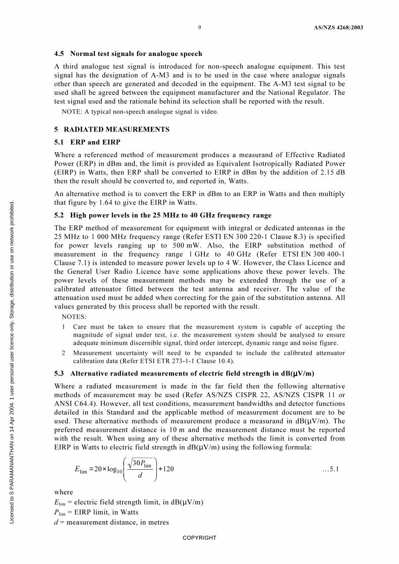
5.3 Alternative radiated measurements of electric field strength in dB(µµµµV/m)
Where a radiated measurement is made in the far field then the following alternative
methods of measurement may be used (Refer AS/NZS CISPR 22, AS/NZS CISPR 11 or
ANSI C64.4). However, all test conditions, measurement bandwidths and detector functions
detailed in this Standard and the applicable method of measurement document are to be
used. These alternative methods of measurement produce a measurand in dB(µV/m). The
preferred measurement distance is 10 m and the measurement distance must be reported
with the result. When using any of these alternative methods the limit is converted from
EIRP in Watts to electric field strength in dB(µV/m) using the following formula:
12030
log20lim
10lim+×=
d
PE …5.1
where
Elim = electric field strength limit, in dB(µV/m)
Plim = EIRP limit, in Watts
d = measurement distance, in metres Lice
nsed
to S
PA
RA
MA
NA
NT
HA
N o
n 14
Apr
200
4. 1
use
r pe
rson
al u
ser
licen
ce o
nly.
Sto
rage
, dis
trib
utio
n or
use
on
netw
ork
proh
ibite
d.
AS/NZS 4268:2003 10
COPYRIGHT
NOTES:
1 When using Open Area Test Site (OATS) alternatives to the substitution test method, results
will be approximately 5 dB higher due to coincidental addition of direct and reflected signals
over a ground plane (Refer ETSI ETR 273-1-1 Clause 7.7.1.2). Consequently, measurement
results obtained over a reflecting ground plane should be reduced by 5 dB before being
compared to the limit, Elim.
2 Where a limit changes amplitude over a band of frequencies, logarithmic interpolation of
frequency (i.e. a straight line on a graph with a logarithmic frequency axis) is to be used.
3 Generally the above alternatives can only be applied above 25 MHz
(Refer ETSI ETR 273-1-1 Clause 7.2).
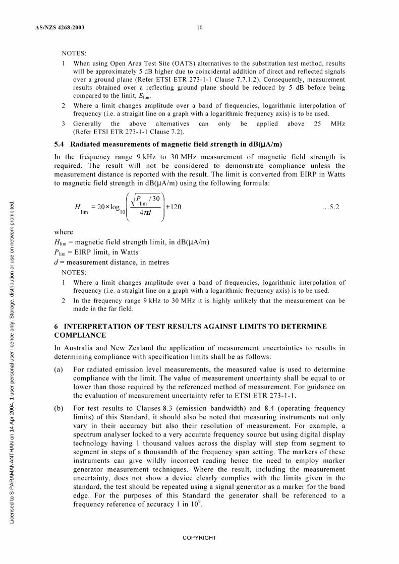
5.4 Radiated measurements of magnetic field strength in dB(µµµµA/m)
In the frequency range 9 kHz to 30 MHz measurement of magnetic field strength is
required. The result will not be considered to demonstrate compliance unless the
measurement distance is reported with the result. The limit is converted from EIRP in Watts
to magnetic field strength in dB(µA/m) using the following formula:
1204
30/log20
lim
10lim+×=
d
P
Hπ
…5.2
where
Hlim = magnetic field strength limit, in dB(µA/m)
Plim = EIRP limit, in Watts
d = measurement distance, in metres
NOTES:
1 Where a limit changes amplitude over a band of frequencies, logarithmic interpolation of
frequency (i.e. a straight line on a graph with a logarithmic frequency axis) is to be used.
2 In the frequency range 9 kHz to 30 MHz it is highly unlikely that the measurement can be
made in the far field.
6 INTERPRETATION OF TEST RESULTS AGAINST LIMITS TO DETERMINE
COMPLIANCE
In Australia and New Zealand the application of measurement uncertainties to results in
determining compliance with specification limits shall be as follows:
(a) For radiated emission level measurements, the measured value is used to determine
compliance with the limit. The value of measurement uncertainty shall be equal to or
lower than those required by the referenced method of measurement. For guidance on
the evaluation of measurement uncertainty refer to ETSI ETR 273-1-1.
(b) For test results to Clauses 8.3 (emission bandwidth) and 8.4 (operating frequency
limits) of this Standard, it should also be noted that measuring instruments not only
vary in their accuracy but also their resolution of measurement. For example, a
spectrum analyser locked to a very accurate frequency source but using digital display
technology having 1 thousand values across the display will step from segment to
segment in steps of a thousandth of the frequency span setting. The markers of these
instruments can give wildly incorrect reading hence the need to employ marker
generator measurement techniques. Where the result, including the measurement
uncertainty, does not show a device clearly complies with the limits given in the
standard, the test should be repeated using a signal generator as a marker for the band
edge. For the purposes of this Standard the generator shall be referenced to a
frequency reference of accuracy 1 in 109.
Lice
nsed
to S
PA
RA
MA
NA
NT
HA
N o
n 14
Apr
200
4. 1
use
r pe
rson
al u
ser
licen
ce o
nly.
Sto
rage
, dis
trib
utio
n or
use
on
netw
ork
proh
ibite
d.
11 AS/NZS 4268:2003
COPYRIGHT
7 FREQUENCY BANDS
The radiofrequency spectrum regulators of Australia and New Zealand do not necessarily
support the use of devices in the frequency bands identified in ETSI documents. ETSI
documents are referred to in this paragraph for their methods of measurement; the limits
provided in this Standard are to be used in conjunction with the referenced methods of
measurement. Unless specifically referenced, the frequency limits provided in the ETSI
document do not apply to Australia or New Zealand.
8 TRANSMITTER PARAMETERS
8.1 Maximum EIRP for Australia and New Zealand
8.1.1 Limits for EIRP
8.1.1.1 Australian limits
Refer to Tables 1 and 2 (Table 3 is provided for reference purposes).
8.1.1.2 New Zealand limits
Refer to the General User Radio Licence.
8.1.2 Methods of measurement for ERP
Equipment and frequency range Method of measurement
Radio equipment 9 kHz to 25 MHz; and,
inductive loop systems 9 kHz to 30 MHz
ETSI EN 300 330-1 V1.3.2
Clause 7.2
Radio equipment 25 MHz to 1000 MHz ETSI EN 300 220-1 V1.3.1
Clause 8.2 for equipment with a permanent
external antenna connector presenting an
impedance of 50Ω; use Clause 8.3 for all
other equipment.
Radio equipment 1 GHz to 40 GHz ETSI EN 300 440-1 V1.3.1
Clause 7.1
NOTES:
1 Frequency bands for specific applications do apply, see the Class Licence and GURL.
2 Where the measurement method states ‘The measure of the effective radiated power is the
larger of the two levels recorded at the input to the substitution antenna, corrected for gain of
the substitution antenna, if necessary.’ Then subtract the calibrated gain of the substitution
antenna from the result..
3 See Clause 5.3 for radiated measurement alternatives.
8.2 Transmitter spurious emissions for Australia and New Zealand
8.2.1 Limits
Limits are specified in clauses 8.2.1.1 and 8.2.1.2 below. For transmitter spurious emissions
above 1GHz, the emissions shall not exceed the limits as specified, but without the need to
be below 1.64µW EIRP (1.0µW ERP).
NOTE: This is in recognition of the rise in measuring receiver noise floor when the test receiver
bandwidth according to CISPR measurement practices is increased from 120kHz to 1MHz above
test frequencies of 1GHz.
8.2.1.1 Australian limits Refer to Tables 1 and 2 (Table 3 is provided for reference purposes).
8.2.1.2 New Zealand limits
Refer to the General User Radio Licence.
Lice
nsed
to S
PA
RA
MA
NA
NT
HA
N o
n 14
Apr
200
4. 1
use
r pe
rson
al u
ser
licen
ce o
nly.
Sto
rage
, dis
trib
utio
n or
use
on
netw
ork
proh
ibite
d.
AS/NZS 4268:2003 12
COPYRIGHT
8.2.2 Methods of measurement for transmitter spurious emissions Australia and New
Zealand
Equipment and frequency range Method of measurement
Radio equipment 9 kHz to 25 MHz; and,
inductive loop systems 9 kHz to 30 MHz
ETSI EN 300 330-1 V1.3.2
Clause 7.4
Radio equipment 25 MHz to 1000 MHz ETSI EN 300 220-1 V1.3.1
Clause 8.7
Radio equipment 1 GHz to 40 GHz ETSI EN 300 440-1 V1.3.1
Clause 7.3
NOTES:
1 See the notes associated with Clause 8.1.2 for measurement guidance.
2 Transmitter spurious emissions are of an unmodulated transmitter.
8.3 Emission bandwidth
8.3.1 Emission bandwidth limits
NOTE: The upper and lower frequency limits of the emission bandwidth shall at all times remain
within the operating frequency limits given in Clause 8.4.
8.3.1.1 Australian limits
Refer to Tables 1 and 2 (Table 3 is provided for reference purposes).
8.3.1.2 New Zealand limits
Refer to the General User Radio Licence
Some transmitter categories require a specific limit for emission bandwidth. In such cases
the emission bandwidth established by testing in accordance with Clause 8.3.2 must not
exceed the specified value.
8.3.2 Method of measurement for emission bandwidth
A spectrum analyser or similar device shall be used to observe a sample of the modulated
transmitter’s radio frequency power output. The frequencies of the upper and lower markers
indicating the edges of the transmitters ‘99% power’ emission bandwidth shall be recorded.
The emission bandwidth shall then be calculated.
When making a measurement of the emission bandwidth:
(a) An rms detector function must be used. The measurement bandwidth used must be
stated with the result. The rms detector used must comply with AS/NZS CISPR 16.
(b) A measurement instrument with an integrated 99% power bandwidth function may be
used to automate the test process.
(c) The measurement instrument bandwidth and span must be set sufficiently wide, and,
the scan time set sufficiently slow, to ensure all major modulation products are
captured. Note that the measurement bandwidth should also be set sufficiently narrow
to avoid adding significant error to the test result.
(d) ‘Maximum Hold’ mode may be used to accumulate the measurement result over
several scans provided the emission is repetitive in nature.
NOTES:
1 For non-speech analogue equipment refer Clause 4.5 regarding the test signal.
2 For telecommand or telemetry transmissions it is desirable to have the transmission enabled
for at least 3 s so that all sidebands and modulation products may be observed.
3 Alternative test methods to the one above may be required for pulse modulated transmitters
(e.g. radar), spread spectrum and more complex digital modulation types.
Lice
nsed
to S
PA
RA
MA
NA
NT
HA
N o
n 14
Apr
200
4. 1
use
r pe
rson
al u
ser
licen
ce o
nly.
Sto
rage
, dis
trib
utio
n or
use
on
netw
ork
proh
ibite
d.
13 AS/NZS 4268:2003
COPYRIGHT
8.4 Operating Frequencies for Australia and New Zealand
8.4.1 Operating frequency limits. (Operation within permitted operating frequency band)
Emission bandwidth shall be within the designated frequency band. This requirement
applies to all transmitters, whether single frequency or multi-channel.
8.4.1.1 Australian limits
Testing is to be conducted under normal and extreme test conditions. Refer to Tables 1 and
2 (Table 3 is provided for reference purposes).
8.4.1.2 New Zealand limits
Refer to the General User Radio Licence. Testing is to be conducted under normal and
extreme test conditions.
8.4.2 Method of measurement for operating frequency in Australia and New Zealand
For testing purposes, multi-channel transmitters may be tested on the highest and lowest
available channels only (for upper and lower band edges respectively), to demonstrate
compliance.
Compliance is determined by using the emission bandwidth test method given in
Clause 8.3.2. The upper and lower frequency limits of the emission bandwidth shall lay
within the permitted frequency band at all times to meet requirements. The test report shall
include details of the modulation scheme used as per Article 2, Appendix 1 of the
International Telecommunication Union Radio Regulation (Edition of 2001).
An alternative method of assessment is to use a combination of results for the measured
emission bandwidth test and frequency stability test performed according to the standards
listed below. If the modulated emission is symmetrical about the carrier frequency, then the
upper and lower frequency limits of the emission can be determined by adding and
subtracting half the emission bandwidth from the unmodulated carrier frequency measured
under all test conditions. This assumes that the application of modulation does not affect
frequency stability.
Equipment and frequency range Method of measurement
Radio equipment 9 kHz to 25 MHz; and,
inductive loop systems 9 kHz to 30 MHz
ETSI EN 300 330-1 V1.3.2
Clause 7.3.2
Radio equipment 25 MHz to 1000 MHz ETSI EN 300 220-1 V1.3.1
Clause 8.6.2
Radio equipment 1 GHz to 40 GHz ETSI EN 300 440-1 V1.3.1
Clause 7.2.2; or, for FHSS use Clause 7.2.3
The designated frequency band is the permitted operating frequency band in Table 1 or 2 or
the operating frequency limits of the GURL.
NOTES:
1 For telecommand or telemetry transmissions it is desirable to have the transmission enabled
for at least 3 s so that all sidebands and modulation products may be observed.
2 Alternative test methods to the one above may be required for pulse modulated transmitters
(e.g. radar), spread spectrum and more complex digital modulation types.
Lice
nsed
to S
PA
RA
MA
NA
NT
HA
N o
n 14
Apr
200
4. 1
use
r pe
rson
al u
ser
licen
ce o
nly.
Sto
rage
, dis
trib
utio
n or
use
on
netw
ork
proh
ibite
d.
AS/NZS 4268:2003 14
COPYRIGHT
9 RECEIVER PARAMETERS
9.1 Receiver emissions
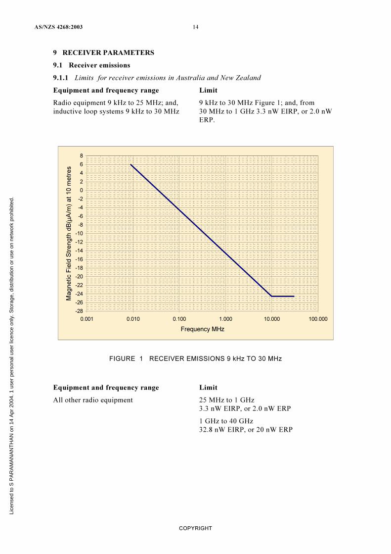
9.1.1 Limits for receiver emissions in Australia and New Zealand
Equipment and frequency range Limit
Radio equipment 9 kHz to 25 MHz; and,
inductive loop systems 9 kHz to 30 MHz
9 kHz to 30 MHz Figure 1; and, from
30 MHz to 1 GHz 3.3 nW EIRP, or 2.0 nW
ERP.
-28
-26
-24
-22
-20
-18
-16
-14
-12
-10
-8
-6
-4
-2
0
2
4
6
8
0.001 0.010 0.100 1.000 10.000 100.000
Frequency MHz
Magnetic F
ield
Str
ength
dB
( µA
/m)
at 10 m
etr
es
FIGURE 1 RECEIVER EMISSIONS 9 kHz TO 30 MHz
Equipment and frequency range Limit
All other radio equipment 25 MHz to 1 GHz
3.3 nW EIRP, or 2.0 nW ERP
1 GHz to 40 GHz
32.8 nW EIRP, or 20 nW ERP
Lice
nsed
to S
PA
RA
MA
NA
NT
HA
N o
n 14
Apr
200
4. 1
use
r pe
rson
al u
ser
licen
ce o
nly.
Sto
rage
, dis
trib
utio
n or
use
on
netw
ork
proh
ibite
d.
15 AS/NZS 4268:2003
COPYRIGHT
9.1.2 Methods of measurement for receiver emissions in Australia and New Zealand
Equipment and frequency range Method of measurement
Radio equipment 9 kHz to 25 MHz; and, ETSI EN 300 330-1 V1.3.2
inductive loop systems 9 kHz to 30 MHz Clause 8.3
Radio equipment 25 MHz to 1000 MHz ETSI EN 300 220-1 V1.3.1
Clause 9.4
Radio equipment 1 GHz to 40 GHz ETSI EN 300 440-1 V1.3.1
Clause 8.4
NOTE: For measurement guidance refer to the notes associated with Clause 8.1.2.
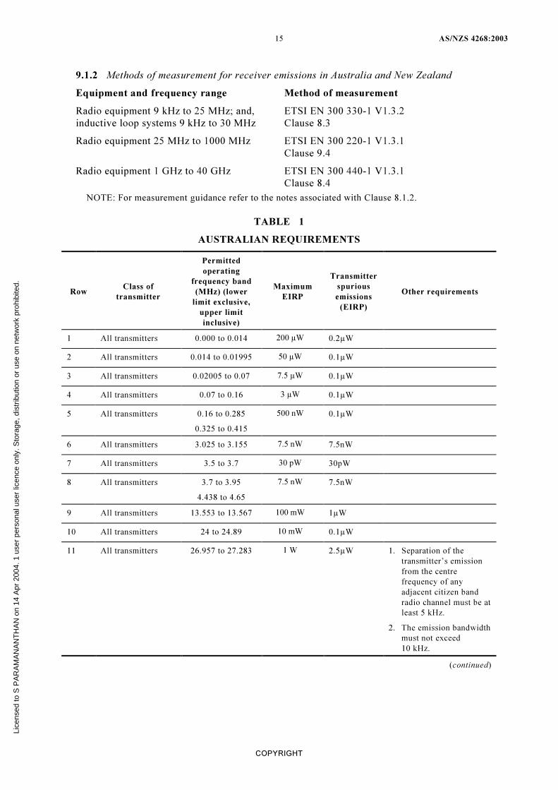
TABLE 1
AUSTRALIAN REQUIREMENTS
Row Class of
transmitter
Permitted
operating
frequency band
(MHz) (lower
limit exclusive,
upper limit
inclusive)
Maximum
EIRP
Transmitter
spurious
emissions
(EIRP)
Other requirements
1 All transmitters 0.000 to 0.014 200 µW 0.2µW
2 All transmitters 0.014 to 0.01995 50 µW 0.1µW
3 All transmitters 0.02005 to 0.07 7.5 µW 0.1µW
4 All transmitters 0.07 to 0.16 3 µW 0.1µW
5 All transmitters 0.16 to 0.285
0.325 to 0.415
500 nW 0.1µW
6 All transmitters 3.025 to 3.155 7.5 nW 7.5nW
7 All transmitters 3.5 to 3.7 30 pW 30pW
8 All transmitters 3.7 to 3.95
4.438 to 4.65
7.5 nW 7.5nW
9 All transmitters 13.553 to 13.567 100 mW 1µW
10 All transmitters 24 to 24.89 10 mW 0.1µW
11 All transmitters 26.957 to 27.283 1 W 2.5µW
1. Separation of the
transmitter’s emission
from the centre
frequency of any
adjacent citizen band
radio channel must be at
least 5 kHz.
2. The emission bandwidth
must not exceed
10 kHz.
(continued)
Lice
nsed
to S
PA
RA
MA
NA
NT
HA
N o
n 14
Apr
200
4. 1
use
r pe
rson
al u
ser
licen
ce o
nly.
Sto
rage
, dis
trib
utio
n or
use
on
netw
ork
proh
ibite
d.
AS/NZS 4268:2003 16
COPYRIGHT
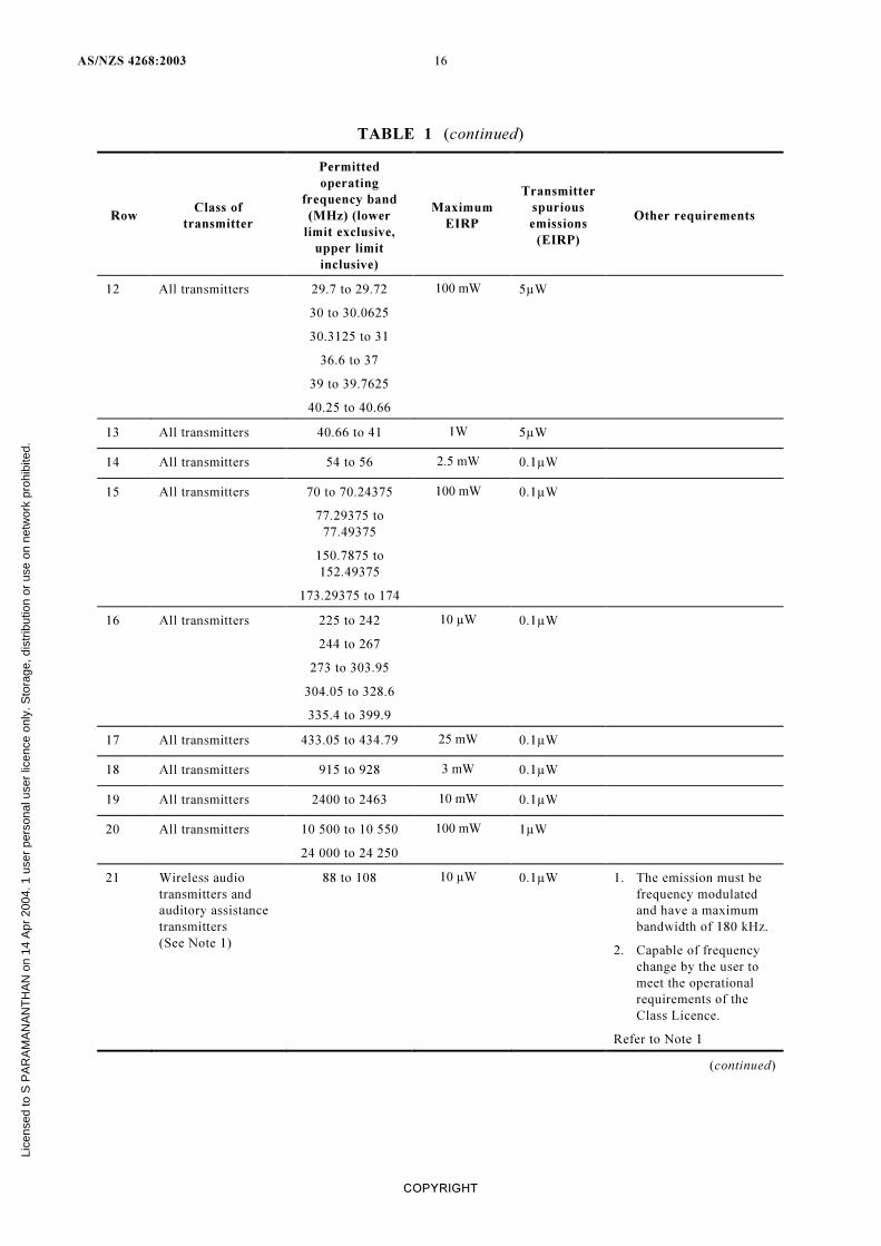
TABLE 1 (continued)
Row Class of
transmitter
Permitted
operating
frequency band
(MHz) (lower
limit exclusive,
upper limit
inclusive)
Maximum
EIRP
Transmitter
spurious
emissions
(EIRP)
Other requirements
12 All transmitters 29.7 to 29.72
30 to 30.0625
30.3125 to 31
36.6 to 37
39 to 39.7625
40.25 to 40.66
100 mW 5µW
13 All transmitters 40.66 to 41 1W 5µW
14 All transmitters 54 to 56 2.5 mW 0.1µW
15 All transmitters 70 to 70.24375
77.29375 to
77.49375
150.7875 to
152.49375
173.29375 to 174
100 mW 0.1µW
16 All transmitters 225 to 242
244 to 267
273 to 303.95
304.05 to 328.6
335.4 to 399.9
10 µW 0.1µW
17 All transmitters 433.05 to 434.79 25 mW 0.1µW
18 All transmitters 915 to 928 3 mW 0.1µW
19 All transmitters 2400 to 2463 10 mW 0.1µW
20 All transmitters 10 500 to 10 550
24 000 to 24 250
100 mW 1µW
21 Wireless audio
transmitters and
auditory assistance
transmitters
(See Note 1)
88 to 108 10 µW 0.1µW 1. The emission must be
frequency modulated
and have a maximum
bandwidth of 180 kHz.
2. Capable of frequency
change by the user to
meet the operational
requirements of the
Class Licence.
Refer to Note 1
(continued)
Lice
nsed
to S
PA
RA
MA
NA
NT
HA
N o
n 14
Apr
200
4. 1
use
r pe
rson
al u
ser
licen
ce o
nly.
Sto
rage
, dis
trib
utio
n or
use
on
netw
ork
proh
ibite
d.
17 AS/NZS 4268:2003
COPYRIGHT
Row Class of
transmitter
Permitted
operating
frequency band
(MHz) (lower
limit exclusive,
upper limit
inclusive)
Maximum
EIRP
Transmitter
spurious
emissions
(EIRP)
Other requirements
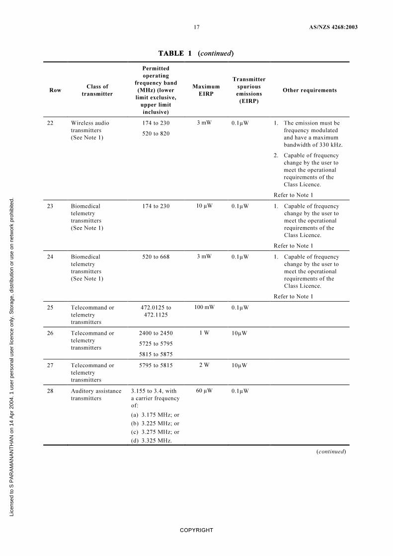
22 Wireless audio
transmitters
(See Note 1)
174 to 230
520 to 820
3 mW 0.1µW 1. The emission must be
frequency modulated
and have a maximum
bandwidth of 330 kHz.
2. Capable of frequency
change by the user to
meet the operational
requirements of the
Class Licence.
Refer to Note 1
23 Biomedical
telemetry
transmitters
(See Note 1)
174 to 230 10 µW 0.1µW 1. Capable of frequency
change by the user to
meet the operational
requirements of the
Class Licence.
Refer to Note 1
24 Biomedical
telemetry
transmitters
(See Note 1)
520 to 668 3 mW 0.1µW 1. Capable of frequency
change by the user to
meet the operational
requirements of the
Class Licence.
Refer to Note 1
25 Telecommand or
telemetry
transmitters
472.0125 to
472.1125
100 mW 0.1µW
26 Telecommand or
telemetry
transmitters
2400 to 2450
5725 to 5795
5815 to 5875
1 W 10µW
27 Telecommand or
telemetry
transmitters
5795 to 5815 2 W 10µW
28 Auditory assistance
transmitters
3.155 to 3.4, with
a carrier frequency
of:
(a) 3.175 MHz; or
(b) 3.225 MHz; or
(c) 3.275 MHz; or
(d) 3.325 MHz.
60 µW 0.1µW
(continued)
TABLE 1 (continued) TABLE 1 (continued)
Lice
nsed
to S
PA
RA
MA
NA
NT
HA
N o
n 14
Apr
200
4. 1
use
r pe
rson
al u
ser
licen
ce o
nly.
Sto
rage
, dis
trib
utio
n or
use
on
netw
ork
proh
ibite
d.
AS/NZS 4268:2003 18
COPYRIGHT
TABLE 1 (continued)
Row Class of
transmitter
Permitted
operating
frequency band
(MHz) (lower
limit exclusive,
upper limit
inclusive)
Maximum
EIRP
Transmitter
spurious
emissions
(EIRP)
Other requirements
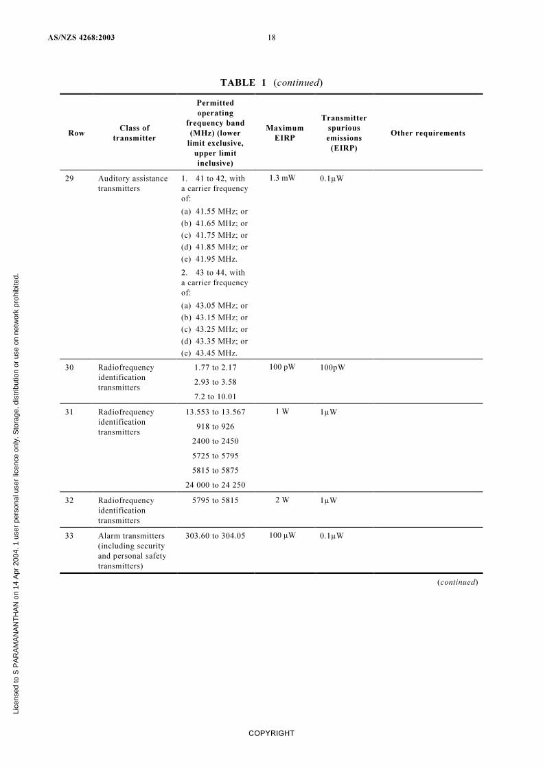
29 Auditory assistance
transmitters
1. 41 to 42, with
a carrier frequency
of:
(a) 41.55 MHz; or
(b) 41.65 MHz; or
(c) 41.75 MHz; or
(d) 41.85 MHz; or
(e) 41.95 MHz.
2. 43 to 44, with
a carrier frequency
of:
(a) 43.05 MHz; or
(b) 43.15 MHz; or
(c) 43.25 MHz; or
(d) 43.35 MHz; or
(e) 43.45 MHz.
1.3 mW 0.1µW
30 Radiofrequency
identification
transmitters
1.77 to 2.17
2.93 to 3.58
7.2 to 10.01
100 pW 100pW
31 Radiofrequency
identification
transmitters
13.553 to 13.567
918 to 926
2400 to 2450
5725 to 5795
5815 to 5875
24 000 to 24 250
1 W 1µW
32 Radiofrequency
identification
transmitters
5795 to 5815 2 W 1µW
33 Alarm transmitters
(including security
and personal safety
transmitters)
303.60 to 304.05 100 µW 0.1µW
(continued)
Lice
nsed
to S
PA
RA
MA
NA
NT
HA
N o
n 14
Apr
200
4. 1
use
r pe
rson
al u
ser
licen
ce o
nly.
Sto
rage
, dis
trib
utio
n or
use
on
netw
ork
proh
ibite
d.
19 AS/NZS 4268:2003
COPYRIGHT
Row Class of
transmitter
Permitted
operating
frequency band
(MHz) (lower
limit exclusive,
upper limit
inclusive)
Maximum
EIRP
Transmitter
spurious
emissions
(EIRP)
Other requirements
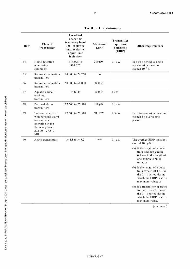
34 Home detention
monitoring
equipment
314.075 to
314.325
200 µW 0.1µW In a 10 s period, a single
transmission must not
exceed 10−3 s.
35 Radio-determination
transmitters
24 000 to 24 250 1 W
36 Radio-determination
transmitters
60 000 to 61 000 20 mW
37 Aquatic-animal-
tracking
transmitters
48 to 49 10 mW 1µW
38 Personal alarm
transmitters
27.500 to 27.510 100 µW 0.1µW
39 Transmitters used
with personal alarm
transmitters
operating in the
frequency band
27.500 – 27.510
MHz
27.500 to 27.510 500 mW 2.5µW Each transmission must not
exceed 4 s over a 60 s
period.
40 Alarm transmitters 344.8 to 345.2 1 mW 0.1µW The average EIRP must not
exceed 100 µW:
(a) if the length of a pulse
train does not exceed
0.1 s— in the length of
one complete pulse
train; or
(b) if the length of a pulse
train exceeds 0.1 s— in
the 0.1 s period during
which the EIRP is at its
maximum value; or
(c) if a transmitter operates
for more than 0.1 s—in
the 0.1 s period during
which the EIRP is at its
maximum value.
(continued)
TABLE 1 (continued)
Lice
nsed
to S
PA
RA
MA
NA
NT
HA
N o
n 14
Apr
200
4. 1
use
r pe
rson
al u
ser
licen
ce o
nly.
Sto
rage
, dis
trib
utio
n or
use
on
netw
ork
proh
ibite
d.
AS/NZS 4268:2003 20
COPYRIGHT
Row Class of
transmitter
Permitted
operating
frequency band
(MHz) (lower
limit exclusive,
upper limit
inclusive)
Maximum
EIRP
Transmitter
spurious
emissions
(EIRP)
Other requirements
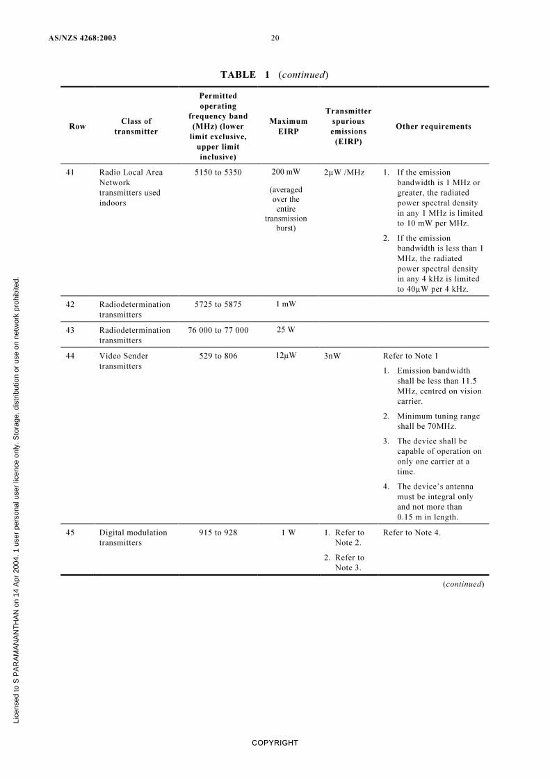
41 Radio Local Area
Network
transmitters used
indoors
5150 to 5350 200 mW
(averaged
over the
entire
transmission
burst)
2µW /MHz 1. If the emission
bandwidth is 1 MHz or
greater, the radiated
power spectral density
in any 1 MHz is limited
to 10 mW per MHz.
2. If the emission
bandwidth is less than 1
MHz, the radiated
power spectral density
in any 4 kHz is limited
to 40µW per 4 kHz.
42 Radiodetermination
transmitters
5725 to 5875 1 mW
43 Radiodetermination
transmitters
76 000 to 77 000 25 W
44 Video Sender
transmitters
529 to 806 12µW 3nW Refer to Note 1
1. Emission bandwidth
shall be less than 11.5
MHz, centred on vision
carrier.
2. Minimum tuning range
shall be 70MHz.
3. The device shall be
capable of operation on
only one carrier at a
time.
4. The device’s antenna
must be integral only
and not more than
0.15 m in length.
45 Digital modulation
transmitters
915 to 928 1 W 1. Refer to
Note 2.
2. Refer to
Note 3.
Refer to Note 4.
(continued)
TABLE 1 (continued)
Lice
nsed
to S
PA
RA
MA
NA
NT
HA
N o
n 14
Apr
200
4. 1
use
r pe
rson
al u
ser
licen
ce o
nly.
Sto
rage
, dis
trib
utio
n or
use
on
netw
ork
proh
ibite
d.
21 AS/NZS 4268:2003
COPYRIGHT
TABLE 1 (continued)
Row Class of
transmitter
Permitted
operating
frequency band
(MHz) (lower
limit exclusive,
upper limit
inclusive)
Maximum
EIRP
Transmitter
spurious
emissions
(EIRP)
Other requirements
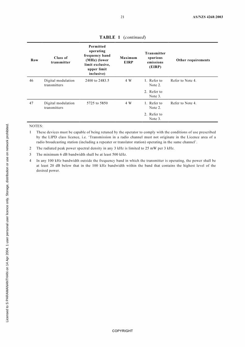
46 Digital modulation
transmitters
2400 to 2483.5 4 W 1. Refer to
Note 2.
2. Refer to
Note 3.
Refer to Note 4.
47 Digital modulation
transmitters
5725 to 5850 4 W 1. Refer to
Note 2.
2. Refer to
Note 3.
Refer to Note 4.
NOTES:
1 These devices must be capable of being retuned by the operator to comply with the conditions of use prescribed
by the LIPD class licence, i.e. ‘Transmission in a radio channel must not originate in the Licence area of a
radio broadcasting station (including a repeater or translator station) operating in the same channel’.
2 The radiated peak power spectral density in any 3 kHz is limited to 25 mW per 3 kHz.
3 The minimum 6 dB bandwidth shall be at least 500 kHz.
4 In any 100 kHz bandwidth outside the frequency band in which the transmitter is operating, the power shall be
at least 20 dB below that in the 100 kHz bandwidth within the band that contains the highest level of the
desired power.
Lice
nsed
to S
PA
RA
MA
NA
NT
HA
N o
n 14
Apr
200
4. 1
use
r pe
rson
al u
ser
licen
ce o
nly.
Sto
rage
, dis
trib
utio
n or
use
on
netw
ork
proh
ibite
d.
AS/NZS 4268:2003 22
COPYRIGHT
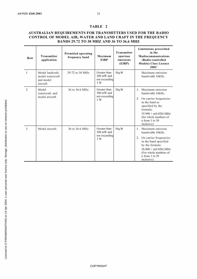
TABLE 2
AUSTRALIAN REQUIREMENTS FOR TRANSMITTERS USED FOR THE RADIO
CONTROL OF MODEL AIR, WATER AND LAND CRAFT IN THE FREQUENCY
BANDS 29.72 TO 30 MHZ AND 36 TO 36.6 MHZ
Row Transmitter
application
Permitted operating
frequency band
Maximum
EIRP
Transmitter
spurious
emissions
(EIRP)
Limitations prescribed
in the
‘Radiocommunications
(Radio-controlled
Models) Class Licence
2002’
1 Model landcraft,
model watercraft
and model
aircraft
29.72 to 30 MHz Greater than
300 mW and
not exceeding
1 W
50µW Maximum emission
bandwidth 10kHz
2 Model
watercraft, and
model aircraft
36 to 36.6 MHz Greater than
300 mW and
not exceeding
1 W
50µW 1. Maximum emission
bandwidth 10kHz.
2. On carrier frequencies
in the band as
specified by the
formula:
35.990 + n(0.020) MHz
(for whole numbers of
n from 1 to 30
inclusive)
3 Model aircraft 36 to 36.6 MHz Greater than
300 mW and
not exceeding
1 W
50µW 1. Maximum emission
bandwidth 10kHz.
2. On carrier frequencies
in the band specified
by the formula:
36.000 + n(0.020) MHz
(For whole numbers of
n from 1 to 29
inclusive)
Lice
nsed
to S
PA
RA
MA
NA
NT
HA
N o
n 14
Apr
200
4. 1
use
r pe
rson
al u
ser
licen
ce o
nly.
Sto
rage
, dis
trib
utio
n or
use
on
netw
ork
proh
ibite
d.
23 AS/NZS 4268:2003
COPYRIGHT
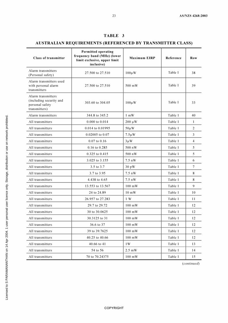
TABLE 3
AUSTRALIAN REQUIREMENTS (REFERENCED BY TRANSMITTER CLASS)
Class of transmitter
Permitted operating
frequency band (MHz) (lower
limit exclusive, upper limit
inclusive)
Maximum EIRP Reference Row
Alarm transmitters
(Personal safety) 27.500 to 27.510 100µW Table 1 38
Alarm transmitters used
with personal alarm
transmitters
27.500 to 27.510 500 mW Table 1 39
Alarm transmitters
(including security and
personal safety
transmitters)
303.60 to 304.05 100µW Table 1 33
Alarm transmitters 344.8 to 345.2 1 mW Table 1 40
All transmitters 0.000 to 0.014 200 µW Table 1 1
All transmitters 0.014 to 0.01995 50µW Table 1 2
All transmitters 0.02005 to 0.07 7.5µW Table 1 3
All transmitters 0.07 to 0.16 3µW Table 1 4
All transmitters 0.16 to 0.285 500 nW Table 1 5
All transmitters 0.325 to 0.415 500 nW Table 1 5
All transmitters 3.025 to 3.155 7.5 nW Table 1 6
All transmitters 3.5 to 3.7 30 pW Table 1 7
All transmitters 3.7 to 3.95 7.5 nW Table 1 8
All transmitters 4.438 to 4.65 7.5 nW Table 1 8
All transmitters 13.553 to 13.567 100 mW Table 1 9
All transmitters 24 to 24.89 10 mW Table 1 10
All transmitters 26.957 to 27.283 1 W Table 1 11
All transmitters 29.7 to 29.72 100 mW Table 1 12
All transmitters 30 to 30.0625 100 mW Table 1 12
All transmitters 30.3125 to 31 100 mW Table 1 12
All transmitters 36.6 to 37 100 mW Table 1 12
All transmitters 39 to 39.7625 100 mW Table 1 12
All transmitters 40.25 to 40.66 100 mW Table 1 12
All transmitters 40.66 to 41 1W Table 1 13
All transmitters 54 to 56 2.5 mW Table 1 14
All transmitters 70 to 70.24375 100 mW Table 1 15
(continued)
Lice
nsed
to S
PA
RA
MA
NA
NT
HA
N o
n 14
Apr
200
4. 1
use
r pe
rson
al u
ser
licen
ce o
nly.
Sto
rage
, dis
trib
utio
n or
use
on
netw
ork
proh
ibite
d.
AS/NZS 4268:2003 24
COPYRIGHT
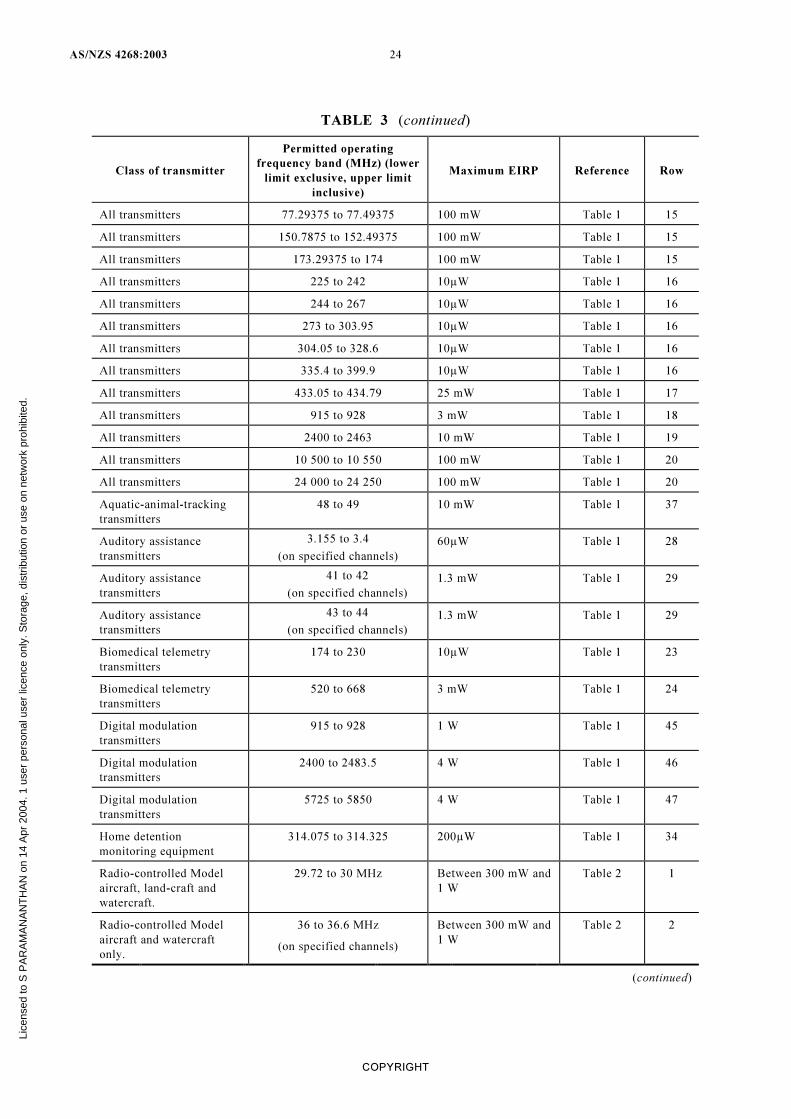
TABLE 3 (continued)
Class of transmitter
Permitted operating
frequency band (MHz) (lower
limit exclusive, upper limit
inclusive)
Maximum EIRP Reference Row
All transmitters 77.29375 to 77.49375 100 mW Table 1 15
All transmitters 150.7875 to 152.49375 100 mW Table 1 15
All transmitters 173.29375 to 174 100 mW Table 1 15
All transmitters 225 to 242 10µW Table 1 16
All transmitters 244 to 267 10µW Table 1 16
All transmitters 273 to 303.95 10µW Table 1 16
All transmitters 304.05 to 328.6 10µW Table 1 16
All transmitters 335.4 to 399.9 10µW Table 1 16
All transmitters 433.05 to 434.79 25 mW Table 1 17
All transmitters 915 to 928 3 mW Table 1 18
All transmitters 2400 to 2463 10 mW Table 1 19
All transmitters 10 500 to 10 550 100 mW Table 1 20
All transmitters 24 000 to 24 250 100 mW Table 1 20
Aquatic-animal-tracking
transmitters
48 to 49 10 mW Table 1 37
Auditory assistance
transmitters
3.155 to 3.4
(on specified channels)
60µW Table 1 28
Auditory assistance
transmitters
41 to 42
(on specified channels)
1.3 mW Table 1 29
Auditory assistance
transmitters
43 to 44
(on specified channels)
1.3 mW Table 1 29
Biomedical telemetry
transmitters
174 to 230 10µW Table 1 23
Biomedical telemetry
transmitters
520 to 668 3 mW Table 1 24
Digital modulation
transmitters
915 to 928 1 W Table 1 45
Digital modulation
transmitters
2400 to 2483.5 4 W Table 1 46
Digital modulation
transmitters
5725 to 5850 4 W Table 1 47
Home detention
monitoring equipment
314.075 to 314.325 200µW Table 1 34
Radio-controlled Model
aircraft, land-craft and
watercraft.
29.72 to 30 MHz Between 300 mW and
1 W
Table 2 1
Radio-controlled Model
aircraft and watercraft
only.
36 to 36.6 MHz
(on specified channels)
Between 300 mW and
1 W
Table 2 2
(continued)
Lice
nsed
to S
PA
RA
MA
NA
NT
HA
N o
n 14
Apr
200
4. 1
use
r pe
rson
al u
ser
licen
ce o
nly.
Sto
rage
, dis
trib
utio
n or
use
on
netw
ork
proh
ibite
d.
25 AS/NZS 4268:2003
COPYRIGHT
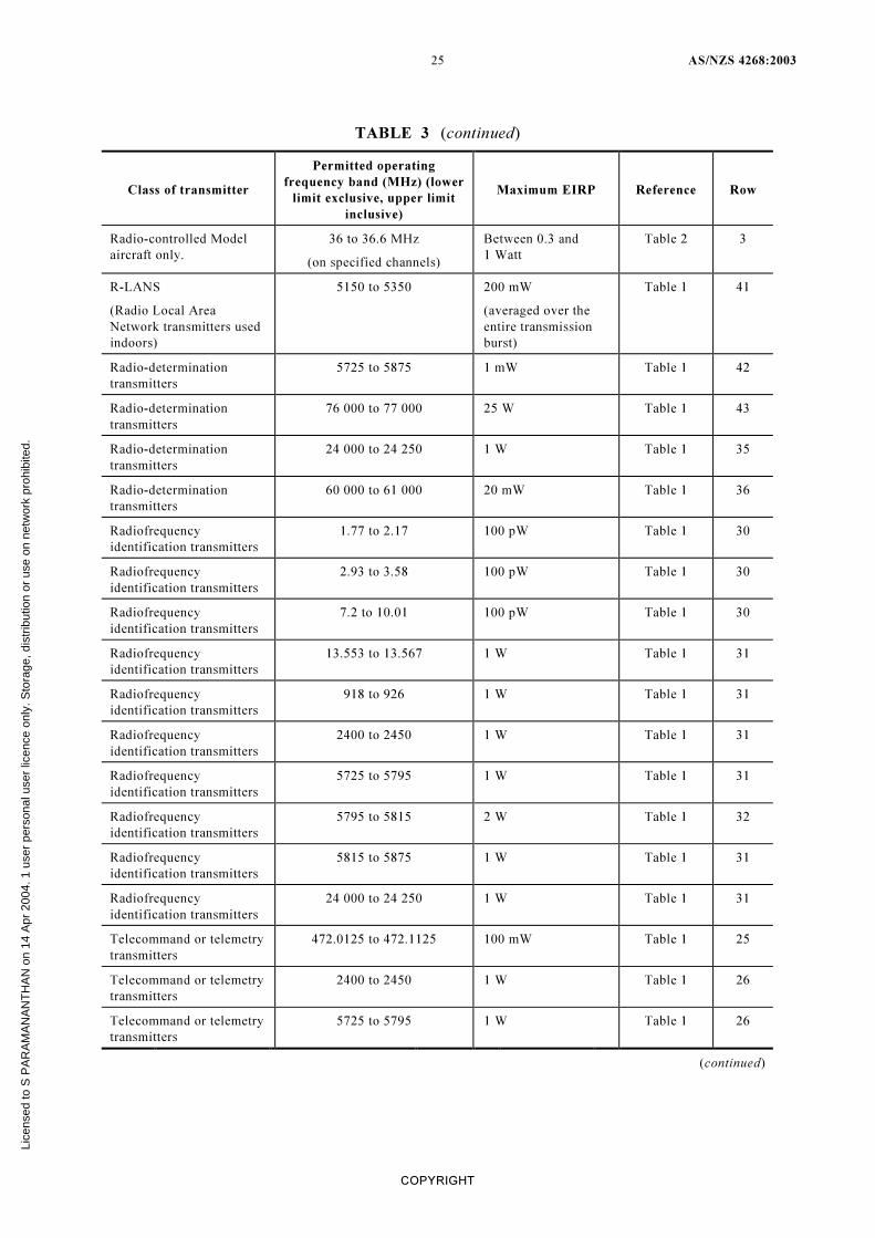
TABLE 3 (continued)
Class of transmitter
Permitted operating
frequency band (MHz) (lower
limit exclusive, upper limit
inclusive)
Maximum EIRP Reference Row
Radio-controlled Model
aircraft only.
36 to 36.6 MHz
(on specified channels)
Between 0.3 and
1 Watt
Table 2 3
R-LANS
(Radio Local Area
Network transmitters used
indoors)
5150 to 5350 200 mW
(averaged over the
entire transmission
burst)
Table 1 41
Radio-determination
transmitters
5725 to 5875 1 mW Table 1 42
Radio-determination
transmitters
76 000 to 77 000 25 W Table 1 43
Radio-determination
transmitters
24 000 to 24 250 1 W Table 1 35
Radio-determination
transmitters
60 000 to 61 000 20 mW Table 1 36
Radiofrequency
identification transmitters
1.77 to 2.17 100 pW Table 1 30
Radiofrequency
identification transmitters
2.93 to 3.58 100 pW Table 1 30
Radiofrequency
identification transmitters
7.2 to 10.01 100 pW Table 1 30
Radiofrequency
identification transmitters
13.553 to 13.567 1 W Table 1 31
Radiofrequency
identification transmitters
918 to 926 1 W Table 1 31
Radiofrequency
identification transmitters
2400 to 2450 1 W Table 1 31
Radiofrequency
identification transmitters
5725 to 5795 1 W Table 1 31
Radiofrequency
identification transmitters
5795 to 5815 2 W Table 1 32
Radiofrequency
identification transmitters
5815 to 5875 1 W Table 1 31
Radiofrequency
identification transmitters
24 000 to 24 250 1 W Table 1 31
Telecommand or telemetry
transmitters
472.0125 to 472.1125 100 mW Table 1 25
Telecommand or telemetry
transmitters
2400 to 2450 1 W Table 1 26
Telecommand or telemetry
transmitters
5725 to 5795 1 W Table 1 26
(continued)
Lice
nsed
to S
PA
RA
MA
NA
NT
HA
N o
n 14
Apr
200
4. 1
use
r pe
rson
al u
ser
licen
ce o
nly.
Sto
rage
, dis
trib
utio
n or
use
on
netw
ork
proh
ibite
d.
AS/NZS 4268:2003 26
COPYRIGHT
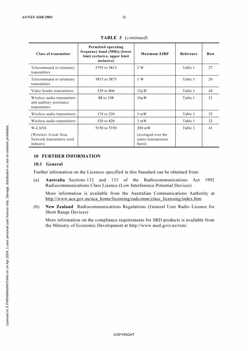
TABLE 3 (continued)
Class of transmitter
Permitted operating
frequency band (MHz) (lower
limit exclusive, upper limit
inclusive)
Maximum EIRP Reference Row
Telecommand or telemetry
transmitters
5795 to 5815 2 W Table 1 27
Telecommand or telemetry
transmitters
5815 to 5875 1 W Table 1 26
Video Sender transmitters 529 to 806 12µW Table 1 44
Wireless audio transmitters
and auditory assistance
transmitters
88 to 108 10µW Table 1 21
Wireless audio transmitters 174 to 230 3 mW Table 1 22
Wireless audio transmitters 520 to 820 3 mW Table 1 22
W-LANS
(Wireless -Local Area
Network transmitters used
indoors)
5150 to 5350 200 mW
(averaged over the
entire transmission
burst)
Table 1 41
10 FURTHER INFORMATION
10.1 General
Further information on the Licences specified in this Standard can be obtained from:
(a) Australia Sections 132 and 135 of the Radiocommunications Act 1992
Radiocommunications Class Licence (Low Interference Potential Devices)
More information is available from the Australian Communications Authority at
http://www.aca.gov.au/aca_home/licensing/radcomm/class_licensing/index.htm
(b) New Zealand Radiocommunications Regulations (General User Radio Licence for
Short Range Devices)
More information on the compliance requirements for SRD products is available from
the Ministry of Economic Development at http://www.med.govt.nz/rsm/.
Lice
nsed
to S
PA
RA
MA
NA
NT
HA
N o
n 14
Apr
200
4. 1
use
r pe
rson
al u
ser
licen
ce o
nly.
Sto
rage
, dis
trib
utio
n or
use
on
netw
ork
proh
ibite
d.
27 AS/NZS 4268:2003
NOTES
Lice
nsed
to S
PA
RA
MA
NA
NT
HA
N o
n 14
Apr
200
4. 1
use
r pe
rson
al u
ser
licen
ce o
nly.
Sto
rage
, dis
trib
utio
n or
use
on
netw
ork
proh
ibite
d.
AS/NZS 4268:2003 28
NOTES
Lice
nsed
to S
PA
RA
MA
NA
NT
HA
N o
n 14
Apr
200
4. 1
use
r pe
rson
al u
ser
licen
ce o
nly.
Sto
rage
, dis
trib
utio
n or
use
on
netw
ork
proh
ibite
d.
Standards Australia
Standards Australia is an independent company, limited by guarantee, which prepares and publishes
most of the voluntary technical and commercial standards used in Australia. These standards are
developed through an open process of consultation and consensus, in which all interested parties are
invited to participate. Through a Memorandum of Understanding with the Commonwealth
government, Standards Australia is recognized as Australia’s peak national standards body.
Standards New Zealand
The first national Standards organization was created in New Zealand in 1932. The Standards
Council of New Zealand is the national authority responsible for the production of Standards.
Standards New Zealand is the trading arm of the Standards Council established under the Standards
Act 1988.
Australian/New Zealand Standards
Under an Active Co-operation Agreement between Standards Australia and Standards New Zealand,
Australian/New Zealand Standards are prepared by committees of experts from industry,
governments, consumers and other sectors. The requirements or recommendations contained
in published Standards are a consensus of the views of representative interests and also take
account of comments received from other sources. They reflect the latest scientific and industry
experience. Australian/New Zealand Standards are kept under continuous review after publication
and are updated regularly to take account of changing technology.
International Involvement
Standards Australia and Standards New Zealand are responsible for ensuring that the Australian
and New Zealand viewpoints are considered in the formulation of international Standards and that
the latest international experience is incorporated in national and Joint Standards. This role is vital
in assisting local industry to compete in international markets. Both organizations are the national
members of ISO (the International Organization for Standardization) and IEC (the International
Electrotechnical Commission).
Visit our Web sites
www.standards.com.au www.standards.co.nz
Lice
nsed
to S
PA
RA
MA
NA
NT
HA
N o
n 14
Apr
200
4. 1
use
r pe
rson
al u
ser
licen
ce o
nly.
Sto
rage
, dis
trib
utio
n or
use
on
netw
ork
proh
ibite
d.
GPO Box 5420 Sydney NSW 2001
Administration
Phone (02) 8206 6000
Fax (02) 8206 6001
Email [email protected]
Customer Service
Phone 1300 65 46 46
Fax 1300 65 49 49
Email [email protected]
Internet www.standards.com.au
Level 10 Radio New Zealand House
155 The Terrace Wellington 6001
(Private Bag 2439 Wellington 6020)
Phone (04) 498 5990
Fax (04) 498 5994
Customer Services (04) 498 5991
Information Service (04) 498 5992
Email [email protected]
Internet www.standards.co.nz
ISBN 0 7337 5540 2 Printed in Australia
Lice
nsed
to S
PA
RA
MA
NA
NT
HA
N o
n 14
Apr
200
4. 1
use
r pe
rson
al u
ser
licen
ce o
nly.
Sto
rage
, dis
trib
utio
n or
use
on
netw
ork
proh
ibite
d.