Embed Size (px)
Citation preview
ASNU Corporation Europe Ltd 65-67 Glencoe Road, Bushey, Herts, WD23 3DP, UK
Tel: +44 (0) 208 4204494 Email: [email protected] Web: www.asnu.com
ASNU Battleship MK2 Fitting Instructions
You will be required to disassemble certain parts from the stock fuel system and then integrate them
into the battleship before reinstalling the system into the tank. If you are unsure of your ability to fit
this kit, we advise that you consult your supplier or a trained mechanic before you start.
Before you commence any work, log any security or access codes that are battery dependant before
disconnecting the battery.
Please ensure that this work is carried out in a well ventilated area away from any possible point of
ignition as fuel or fuel vapour will be present and could present a fire hazard.
We advise the use of appropriate clothing and safety glasses
Also ensure that a fire extinguisher of the appropriate type is available.
When working with fuel we advise that the correct protective equipment is worn including glasses
and gloves where appropriate.
Kit Contents:
Battleship main assembly
Stainless steel fuel module lid complete with quick connect scavenge connectors
Fuel return pipe with quick connect connector
Fuel pickup pipes with filters
Appropriate flange mounting bolts
Male 4-way connector and terminals
Cable ties
Hose clamps
ASNU Corporation Europe Ltd 65-67 Glencoe Road, Bushey, Herts, WD23 3DP, UK
Tel: +44 (0) 208 4204494 Email: [email protected] Web: www.asnu.com
Section 1: System removal
Prepare car by running it until the fuel warning lamp is illuminated leaving only 15 /
20 litres of fuel in the tank
Open vehicle windows fully to allow fumes to vent
Disconnect vehicle battery and remove any sources of ignition from the work area
Remove rear seat squab in line with Nissan workshop manual
Remove tank cover plate from floor plan
Disconnect fuel module electrical harnesses
Remove OE fuel module in line with Nissan workshop manual
Refit tank cover plate temporarily to prevent excess fuel vapour entering the car
whilst the fuel system is being prepared.
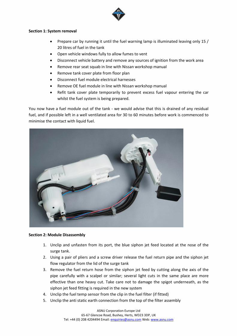
You now have a fuel module out of the tank - we would advise that this is drained of any residual
fuel, and if possible left in a well ventilated area for 30 to 60 minutes before work is commenced to
minimise the contact with liquid fuel.
Section 2: Module Disassembly
1. Unclip and unfasten from its port, the blue siphon jet feed located at the nose of the
surge tank.
2. Using a pair of pliers and a screw driver release the fuel return pipe and the siphon jet
flow regulator from the lid of the surge tank
3. Remove the fuel return hose from the siphon jet feed by cutting along the axis of the
pipe carefully with a scalpel or similar; several light cuts in the same place are more
effective than one heavy cut. Take care not to damage the spigot underneath, as the
siphon jet feed fitting is required in the new system
4. Unclip the fuel temp sensor from the clip in the fuel filter (if fitted)
5. Unclip the anti static earth connection from the top of the filter assembly
ASNU Corporation Europe Ltd 65-67 Glencoe Road, Bushey, Herts, WD23 3DP, UK
Tel: +44 (0) 208 4204494 Email: [email protected] Web: www.asnu.com
6. The surge tank can now be disassembled.
7. Around the side of the surge tank are 4 locking tags. Starting at the front of the tank
unclip with a small flat blade screw driver each of the lock tabs in turn. It may be
nessecery to wedge the lock tab up to prevent it relocking when you move onto the next
tab. We advise the use of a wooden coffee stirrer cut into short lengths for this.
8. Remove the tank level sensor from the OE top plate by depressing the locking leg and
sliding upwards towards the top plate
9. Disconnect the wiring for the sensors from the underside of the top plate
10. You will require the module base, the level and fuel temp sensors with their wiring, and
the siphon feed jet. Separate these parts for reuse
11. Safely store the remaining parts of the OE module (top plate, pump & filter assembly).
These will still have residual fuel in so should be stored in a well ventilated area free
from sources of ignition
Section 3: Reassembly of Fuel Module & return fuel line.
1. Insert end of the return hose (without quick connect fitting) into a cup of boiling water
and leave to soften for 5 mins - it may need to be stretched slightly which can be
performed by inserting a pair of long nose pliers and gently opening them to stretch the
hose
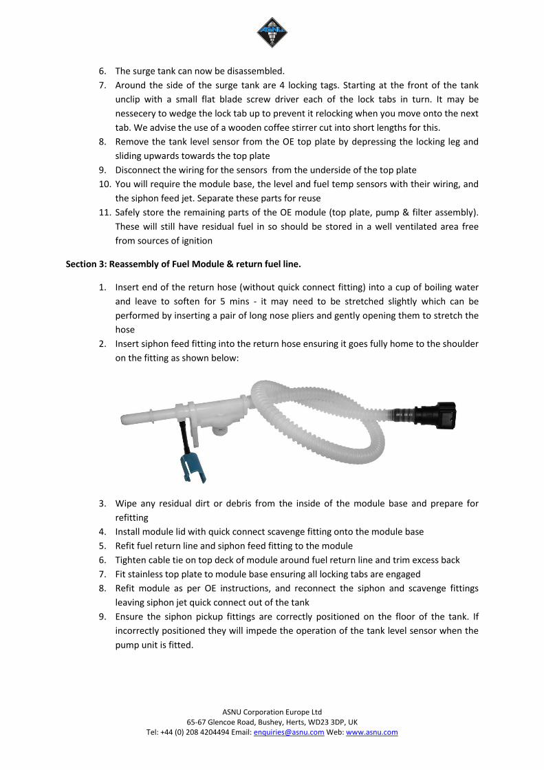
2. Insert siphon feed fitting into the return hose ensuring it goes fully home to the shoulder
on the fitting as shown below:
3. Wipe any residual dirt or debris from the inside of the module base and prepare for
refitting
4. Install module lid with quick connect scavenge fitting onto the module base
5. Refit fuel return line and siphon feed fitting to the module
6. Tighten cable tie on top deck of module around fuel return line and trim excess back
7. Fit stainless top plate to module base ensuring all locking tabs are engaged
8. Refit module as per OE instructions, and reconnect the siphon and scavenge fittings
leaving siphon jet quick connect out of the tank
9. Ensure the siphon pickup fittings are correctly positioned on the floor of the tank. If
incorrectly positioned they will impede the operation of the tank level sensor when the
pump unit is fitted.
ASNU Corporation Europe Ltd 65-67 Glencoe Road, Bushey, Herts, WD23 3DP, UK
Tel: +44 (0) 208 4204494 Email: [email protected] Web: www.asnu.com
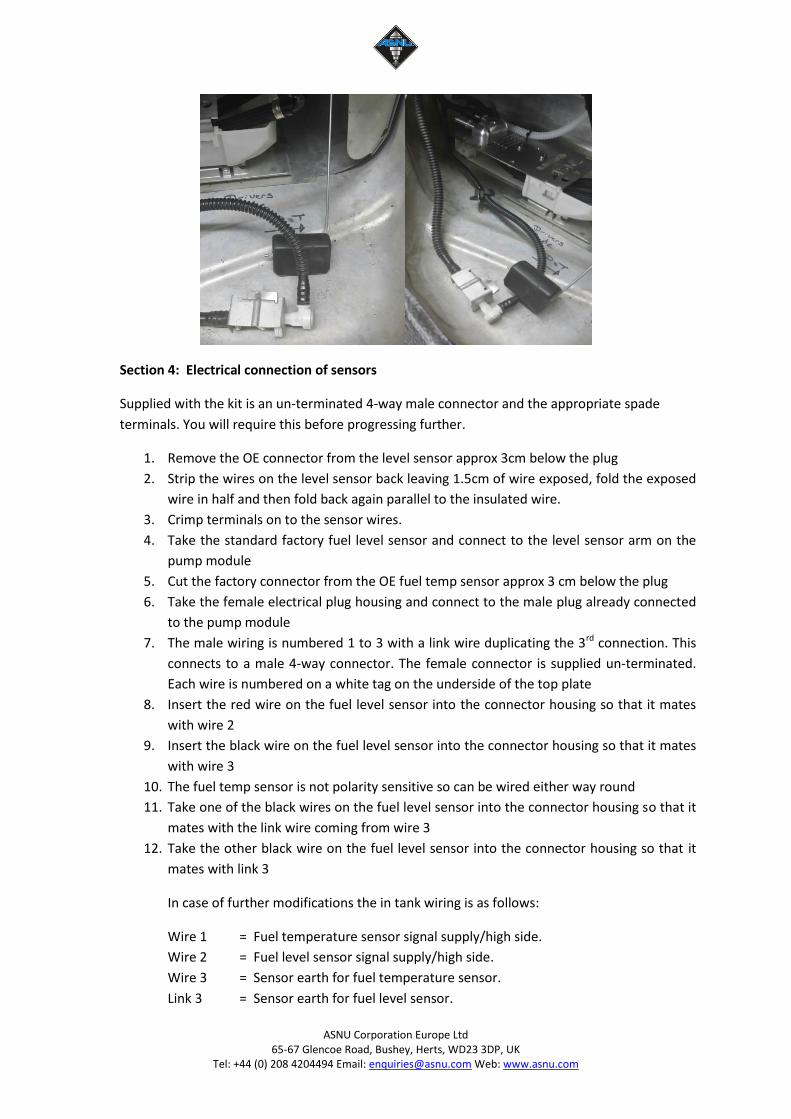
Section 4: Electrical connection of sensors
Supplied with the kit is an un-terminated 4-way male connector and the appropriate spade
terminals. You will require this before progressing further.
1. Remove the OE connector from the level sensor approx 3cm below the plug
2. Strip the wires on the level sensor back leaving 1.5cm of wire exposed, fold the exposed
wire in half and then fold back again parallel to the insulated wire.
3. Crimp terminals on to the sensor wires.
4. Take the standard factory fuel level sensor and connect to the level sensor arm on the
pump module
5. Cut the factory connector from the OE fuel temp sensor approx 3 cm below the plug
6. Take the female electrical plug housing and connect to the male plug already connected
to the pump module
7. The male wiring is numbered 1 to 3 with a link wire duplicating the 3rd connection. This
connects to a male 4-way connector. The female connector is supplied un-terminated.
Each wire is numbered on a white tag on the underside of the top plate
8. Insert the red wire on the fuel level sensor into the connector housing so that it mates
with wire 2
9. Insert the black wire on the fuel level sensor into the connector housing so that it mates
with wire 3
10. The fuel temp sensor is not polarity sensitive so can be wired either way round
11. Take one of the black wires on the fuel level sensor into the connector housing so that it
mates with the link wire coming from wire 3
12. Take the other black wire on the fuel level sensor into the connector housing so that it
mates with link 3
In case of further modifications the in tank wiring is as follows:
Wire 1 = Fuel temperature sensor signal supply/high side.
Wire 2 = Fuel level sensor signal supply/high side.
Wire 3 = Sensor earth for fuel temperature sensor.
Link 3 = Sensor earth for fuel level sensor.
ASNU Corporation Europe Ltd 65-67 Glencoe Road, Bushey, Herts, WD23 3DP, UK
Tel: +44 (0) 208 4204494 Email: [email protected] Web: www.asnu.com
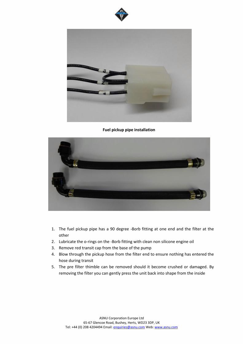
Fuel pickup pipe installation
1. The fuel pickup pipe has a 90 degree -8orb fitting at one end and the filter at the
other
2. Lubricate the o-rings on the -8orb fitting with clean non silicone engine oil
3. Remove red transit cap from the base of the pump
4. Blow through the pickup hose from the filter end to ensure nothing has entered the
hose during transit
5. The pre filter thimble can be removed should it become crushed or damaged. By
removing the filter you can gently press the unit back into shape from the inside
ASNU Corporation Europe Ltd 65-67 Glencoe Road, Bushey, Herts, WD23 3DP, UK
Tel: +44 (0) 208 4204494 Email: [email protected] Web: www.asnu.com
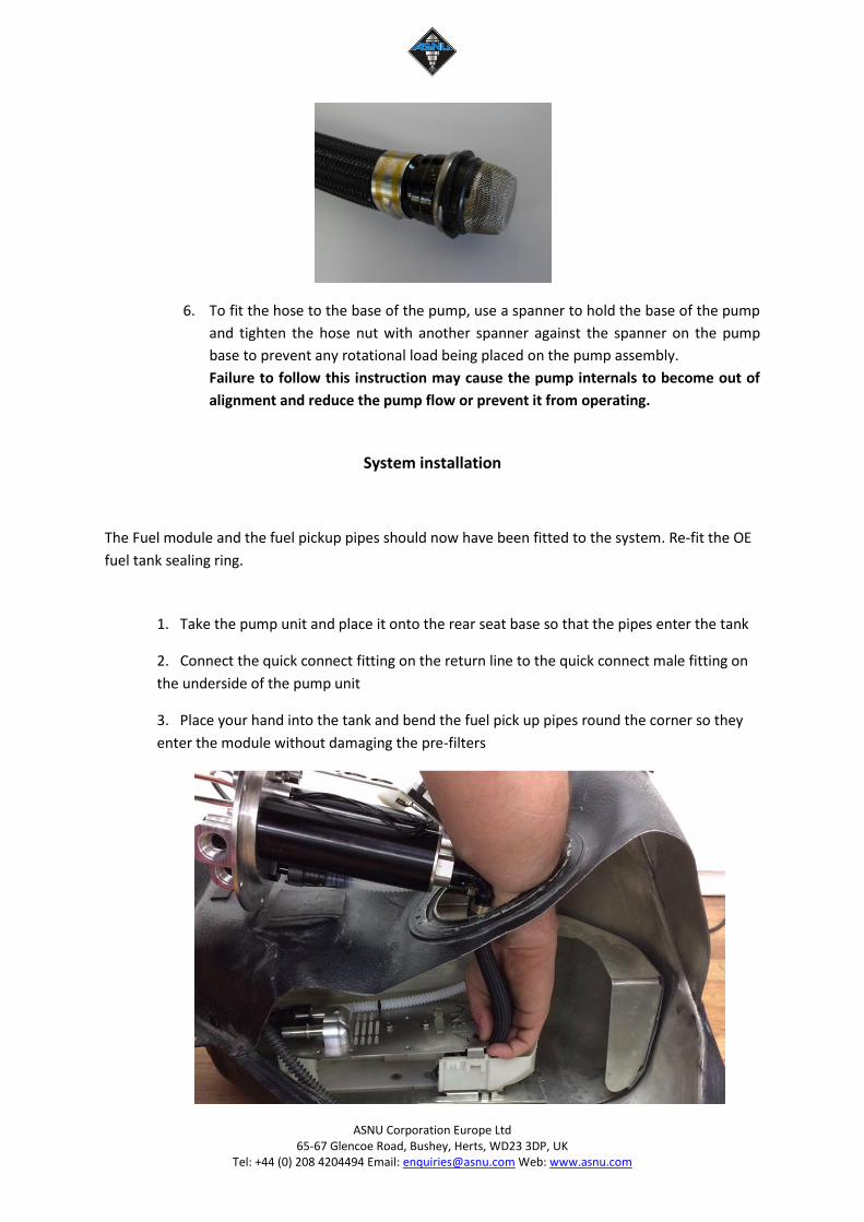
6. To fit the hose to the base of the pump, use a spanner to hold the base of the pump
and tighten the hose nut with another spanner against the spanner on the pump
base to prevent any rotational load being placed on the pump assembly.
Failure to follow this instruction may cause the pump internals to become out of
alignment and reduce the pump flow or prevent it from operating.
System installation
The Fuel module and the fuel pickup pipes should now have been fitted to the system. Re-fit the OE
fuel tank sealing ring.
1. Take the pump unit and place it onto the rear seat base so that the pipes enter the tank
2. Connect the quick connect fitting on the return line to the quick connect male fitting on
the underside of the pump unit
3. Place your hand into the tank and bend the fuel pick up pipes round the corner so they
enter the module without damaging the pre-filters
ASNU Corporation Europe Ltd 65-67 Glencoe Road, Bushey, Herts, WD23 3DP, UK
Tel: +44 (0) 208 4204494 Email: [email protected] Web: www.asnu.com
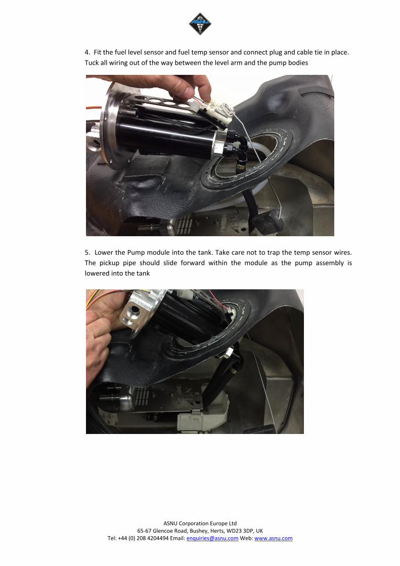
4. Fit the fuel level sensor and fuel temp sensor and connect plug and cable tie in place.
Tuck all wiring out of the way between the level arm and the pump bodies
5. Lower the Pump module into the tank. Take care not to trap the temp sensor wires.
The pickup pipe should slide forward within the module as the pump assembly is
lowered into the tank
ASNU Corporation Europe Ltd 65-67 Glencoe Road, Bushey, Herts, WD23 3DP, UK
Tel: +44 (0) 208 4204494 Email: [email protected] Web: www.asnu.com
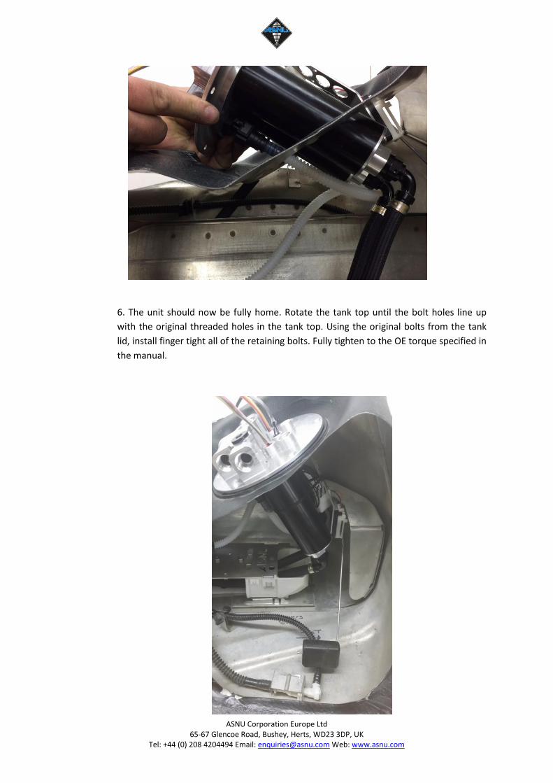
6. The unit should now be fully home. Rotate the tank top until the bolt holes line up
with the original threaded holes in the tank top. Using the original bolts from the tank
lid, install finger tight all of the retaining bolts. Fully tighten to the OE torque specified in
the manual.
ASNU Corporation Europe Ltd 65-67 Glencoe Road, Bushey, Herts, WD23 3DP, UK
Tel: +44 (0) 208 4204494 Email: [email protected] Web: www.asnu.com
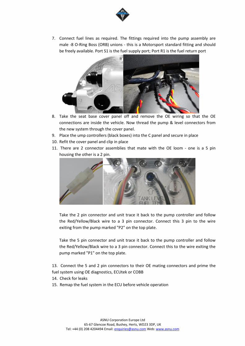
7. Connect fuel lines as required. The fittings required into the pump assembly are
male -8 O-Ring Boss (ORB) unions - this is a Motorsport standard fitting and should
be freely available. Port S1 is the fuel supply port; Port R1 is the fuel return port
8. Take the seat base cover panel off and remove the OE wiring so that the OE
connections are inside the vehicle. Now thread the pump & level connectors from
the new system through the cover panel.
9. Place the ump controllers (black boxes) into the C panel and secure in place
10. Refit the cover panel and clip in place
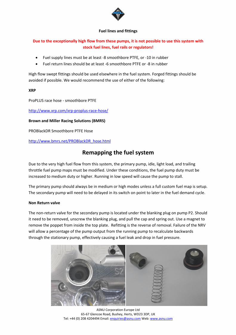
11. There are 2 connector assemblies that mate with the OE loom - one is a 5 pin
housing the other is a 2 pin.
Take the 2 pin connector and unit trace it back to the pump controller and follow
the Red/Yellow/Black wire to a 3 pin connector. Connect this 3 pin to the wire
exiting from the pump marked "P2" on the top plate.
Take the 5 pin connector and unit trace it back to the pump controller and follow
the Red/Yellow/Black wire to a 3 pin connector. Connect this to the wire exiting the
pump marked "P1" on the top plate.
13. Connect the 5 and 2 pin connectors to their OE mating connectors and prime the
fuel system using OE diagnostics, ECUtek or COBB
14. Check for leaks
15. Remap the fuel system in the ECU before vehicle operation
ASNU Corporation Europe Ltd 65-67 Glencoe Road, Bushey, Herts, WD23 3DP, UK
Tel: +44 (0) 208 4204494 Email: [email protected] Web: www.asnu.com
Fuel lines and fittings
Due to the exceptionally high flow from these pumps, it is not possible to use this system with
stock fuel lines, fuel rails or regulators!
Fuel supply lines must be at least -8 smoothbore PTFE, or -10 in rubber
Fuel return lines should be at least -6 smoothbore PTFE or -8 in rubber
High flow swept fittings should be used elsewhere in the fuel system. Forged fittings should be
avoided if possible. We would recommend the use of either of the following:
XRP
ProPLUS race hose - smoothbore PTFE
http://www.xrp.com/xrp-proplus-race-hose/
Brown and Miller Racing Solutions (BMRS)
PROBlackDR Smoothbore PTFE Hose
http://www.bmrs.net/PROBlackDR_hose.html
Remapping the fuel system
Due to the very high fuel flow from this system, the primary pump, idle, light load, and trailing
throttle fuel pump maps must be modified. Under these conditions, the fuel pump duty must be
increased to medium duty or higher. Running in low speed will cause the pump to stall.
The primary pump should always be in medium or high modes unless a full custom fuel map is setup.
The secondary pump will need to be delayed in its switch on point to later in the fuel demand cycle.
Non Return valve
The non-return valve for the secondary pump is located under the blanking plug on pump P2. Should
it need to be removed, unscrew the blanking plug, and pull the cap and spring out. Use a magnet to
remove the poppet from inside the top plate. Refitting is the reverse of removal. Failure of the NRV
will allow a percentage of the pump output from the running pump to recalculate backwards
through the stationary pump, effectively causing a fuel leak and drop in fuel pressure.
ASNU Corporation Europe Ltd 65-67 Glencoe Road, Bushey, Herts, WD23 3DP, UK
Tel: +44 (0) 208 4204494 Email: [email protected] Web: www.asnu.com
Pump swap
In an emergency, the primary pump can be swapped with the secondary unit by swapping the
connectors P1 and P2. The non return poppet will need to be swapped with pump P1 as outlined
above.
Filters
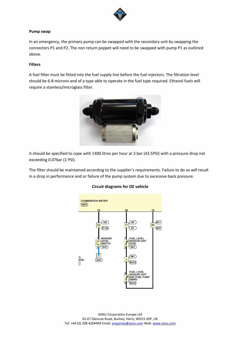
A fuel filter must be fitted into the fuel supply line before the fuel injectors. The filtration level
should be 6-8 microns and of a type able to operate in the fuel type required. Ethanol fuels will
require a stainless/microglass filter.
It should be specified to cope with 1400 litres per hour at 3 bar (43.5PSI) with a pressure drop not
exceeding 0.07bar (1 PSI).
The filter should be maintained according to the supplier’s requirements. Failure to do so will result
in a drop in performance and or failure of the pump system due to excessive back pressure.
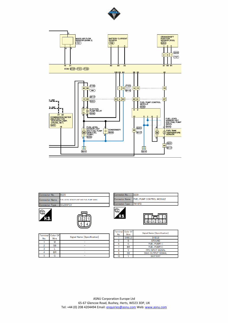
Circuit diagrams for OE vehicle
ASNU Corporation Europe Ltd 65-67 Glencoe Road, Bushey, Herts, WD23 3DP, UK
Tel: +44 (0) 208 4204494 Email: [email protected] Web: www.asnu.com
ASNU Corporation Europe Ltd 65-67 Glencoe Road, Bushey, Herts, WD23 3DP, UK
Tel: +44 (0) 208 4204494 Email: [email protected] Web: www.asnu.com
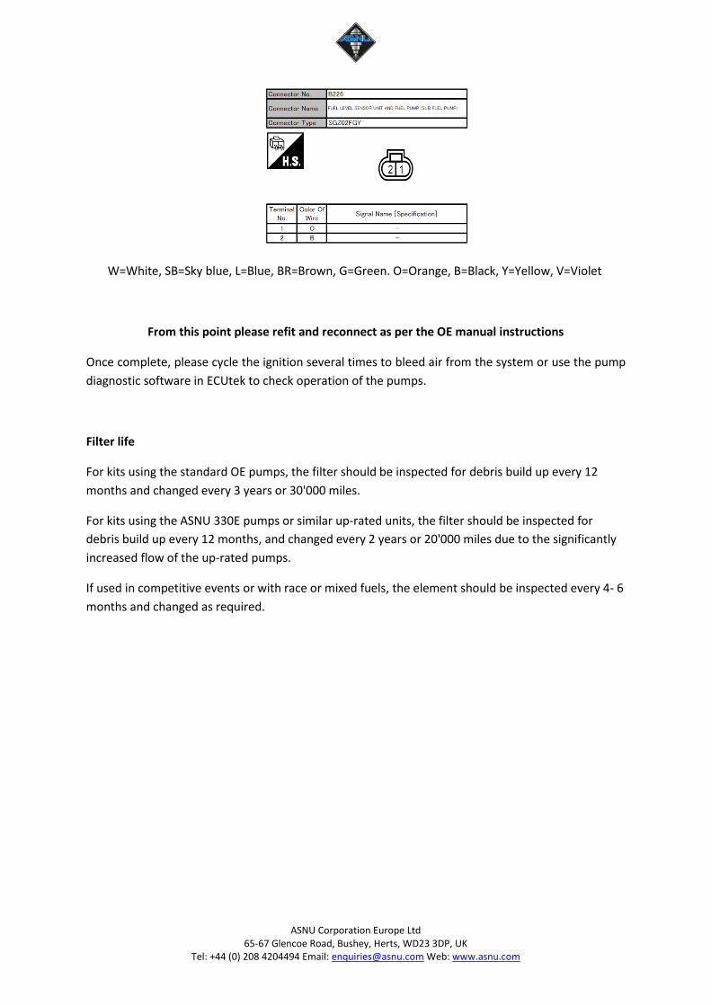
W=White, SB=Sky blue, L=Blue, BR=Brown, G=Green. O=Orange, B=Black, Y=Yellow, V=Violet
From this point please refit and reconnect as per the OE manual instructions
Once complete, please cycle the ignition several times to bleed air from the system or use the pump
diagnostic software in ECUtek to check operation of the pumps.
Filter life
For kits using the standard OE pumps, the filter should be inspected for debris build up every 12
months and changed every 3 years or 30'000 miles.
For kits using the ASNU 330E pumps or similar up-rated units, the filter should be inspected for
debris build up every 12 months, and changed every 2 years or 20'000 miles due to the significantly
increased flow of the up-rated pumps.
If used in competitive events or with race or mixed fuels, the element should be inspected every 4- 6
months and changed as required.