Embed Size (px)
DESCRIPTION
orifice flange design standards
Citation preview
INDD BZb.36 88 - 2595512 0078093 T48 -
ASME-B16.36
ADOPTION NOTICE
ASME-B16.36, "Flanges, Orifice," was adopted on October 3, 1994 for use by the Department of Defense (DOD). Proposed changes by DOD activities must be submitted to the DOD Adopting Activity: Commanding Officer, Naval Construction Battalion Center, Code 156, 1000 23rd Avenue, Port Hueneme, CA 93043-4301. DOD activities may obtain copies of this standard from the Standardization Document Order Desk, 700 Robbins Avenue, Building 4D, Philadelphia, PA 19111-5094. The private sector and other Government agencies may purchase copies from the American Society of Mechanical Engineers, 345 East 47th Street, New York, NY 10017.
Custodians: Army - ME Navy - YD-1 Air Force - 99
Adopting Activity Navy - YD-1
.
FSC 4730
DISTRIBUTION STATEMENT A. Approved for public release; distribution is unlimited.
COPYRIGHT American Society of Mechanical EngineersLicensed by Information Handling ServicesCOPYRIGHT American Society of Mechanical EngineersLicensed by Information Handling Services
INDD B1|I=.3I= BB _ E5“l551|E EIEI'?BU“l3 Tll —
ASME-B16.36
ADOPTION NOTICE
ASME—B16.36, "Flanges, Orifice," was adopted on October 3,1994 for use by the Department of Defense (DoD). Proposedchanges by DoD activities must be submitted to the DoDAdopting Activity: Commanding Officer, Naval ConstructionBattalion Center, Code 156, 1000 23rd Avenue, Port Hueneme,CA 93043-4301. DoD activities may obtain copies of thisstandard from the Standardization Document Order Desk, 700Robbins Avenue, Building 4D, Philadelphia, PA 19111-5094.The private sector and other Government agencies maypurchase copies from the American Society of MechanicalEngineers, 345 East 47th Street, New York, NY 10017.
Custodians: Adopting ActivityArmy - ME Navy — YD—lNavy — YD—lAir Force — 99
FSC 4730
DISTRIBUTION STATEMENT A. Approved for public release;distribution is unlimited.

COPYRIGHT American Society of Mechanical EngineersLicensed by Information Handling ServicesCOPYRIGHT American Society of Mechanical EngineersLicensed by Information Handling Services
/\
v
\
STD - ASHE BLl= - Eil=—ENGL 1.=i=ii= I U?5'=ii=?U u5?=1e=i1. TH '-I u at
(Revision nl ASME/ANSI Biii.3B-1988)
ll|i|F||JEFU\|\|[iESAN AMERICAN NATIONALSTANDARD
-1 The American Society of® Mechanical Engineers
~~ -
STD-ASME B l b - 3 b - E N G L L77b - 0757b70 0577272 980
The American Society of Mechanical Engineers
A N A M E R I C A N N A T I O N A L S T A N D A R D
ORIFICE LANCES .
ASME B16.36-1996 (Revision of ASMVANSI B16.36-1988)
COPYRIGHT American Society of Mechanical EngineersLicensed by Information Handling ServicesCOPYRIGHT American Society of Mechanical EngineersLicensed by Information Handling Services
STD ASHE B1ii= ai. ENGL ]i‘i'=ib I nvsaevu i;i5?=ia'=ia aiici I
The American Society oi® Mechanical Engineers
AN AMERICAN NATIONAL STANDARD
lllililllli FU\l\|liES
ASME B1B.3li—199Biniiiiiii ii iisiiii/iiiisi iiiiiriii-iiiasi
, STD-ASME B L b - 3 b - E N G L L77b 0757b70 0577273 AL7
Date of Issuance: January 31, 1997
The 1996 edition of this Standard is being issued with an automatic addenda subscription service. The use of an addenda allows revisions made in response to public review comments or committee actions to be published as necessary; revisions published in addenda will become effective 6 months after the Date of Issuance of the addenda. The next edition of this Standard is scheduled for publication in 2001.
ASME issues written replies to inquiries concerning interpretations of technical aspects of this Standard. The interpretations will be included with the above addenda service. Interpretations are not part of the addenda to the Standard.
ASME is the registered trademark of the American Society of Mechanical Engineers.
This code or standard was developed under procedures accredited as meeting the criteria for American National Standards. The Consensus Committee that approved the code or standard was balanced to assure that individuals from competent and concerned interests have had an opportunity to participate. The proposed code or standard was made available for public review and comment which provides an opportunity for additional public input from industry, academia, regulatory agencies, and the public-at-large.
ASME does not "approve," "rate," or "endorse" any item, construction, proprietary device, or activity.
ASME does not take any position with respect to the validity of any patent rights asserted in connection with any items mentioned in this document, and does not undertake to insure anyone utilizing a standard against liability for infringement of any applicable Letters Patent, nor assume any such liability. Users of a code or standard are expressly advised that determination of the validity of any such patent rights, and the risk of infringement of such rights, is entirely their own responsibility.
Participation by federal agency representative(s1 or person(s) affiliated with industry is not to be interpreted as government or industry endorsement of this code or standard.
ASME accepts responsibility for only those interpretations issued in accordance with governing ASME procedures and policies which preclude the issuance of interpretations by individual volunteers.
No part of this document may be reproduced in any form, in an electronic retrieval system or otherwise,
without the prior written permission of the publisher.
The American Society of Mechanical Engineers 345 East 47th Street, New York, NY 10017
Copyright Q 1997 by THE AMERICAN SOCIETY OF MECHANICAL ENGINEERS
All Rights Reserved Printed in U.S.A.
COPYRIGHT American Society of Mechanical EngineersLicensed by Information Handling ServicesCOPYRIGHT American Society of Mechanical EngineersLicensed by Information Handling Services
STD-ASHE B1il=-Ell;-ENGL ]i'=l“lb I |J75“ll=?D El57'3E'=l3 Elli? K
Date of Issuance: January 31, 1997
The 1996 edition of this Standard is being issued with an automatic addendasubscription service. The use of an addenda allows revisions made in responseto public review comments or committee actions to be published as necessary;revisions published in addenda will become effective 6 months after the Dateof Issuance of the addenda. The next edition of this Standard is scheduled forpublication in 2001.
ASME issues written replies to inquiries concerning interpretations of technicalaspects of this Standard. The interpretations will be included with the aboveaddenda sen/ice. Interpretations are not part of the addenda to the Standard.
ASME is the registered trademark of the American Society of Mechanical Engineers.
This code or standard was developed under procedures accredited as meeting the criteria forAmerican National Standards. The Consensus Committee that approved the code or standard wasbalanced to assure that individuals from competent and concerned interests have had anopportunity to participate. The proposed code or standard was made available for public reviewand comment which provides an opportunity for additional public input from industry, academia,regulatory agencies, and the public-at-large.
ASME does not "approve," "rate," or "endorse" any item, construction, proprietary device, oractivity.
ASME does not take any position with respect to the validity of any patent rights asserted inconnection with any items mentioned in this document, and does not undertake to insureanyoneutilizing a standard against liability for infringement of any applicable Letters Patent, nor assumeany such liability. Users of a code or standard are expressly advised that determination of thevalidity oi any such patent rights, and the risk of infringement of such rights, is entirely their ownresponsibility.
Participation by federal agency representetivelsl or personlsl affiliated with industry is not to beinterpreted as government or industry endorsement of this code or standard.
ASME accepts responsibility for only those interpretations issued in accordance with governingASME procedures and policies which preclude the issuance of interpretations by individualvolunteers.
No part of this document may be reproduced in any form,in an electronic retrieval system or otherwise,
without the prior written permission of the publisher.
The American Society of Mechanical Engineers345 East 47th Street, New York, NY 10017
Copyright © 1997 byTHE AMERICAN SOCIETY OF MECHANICAL ENGINEERS
All Rights Resen/edPrinted in U.S.A.
FOREWORD
(This Foreword is not part of ASME 616.36-1996.)
August of 1956 marked the first recorded correspondence noting the lack of standardization for orifice flanges. There were, and still are, several codes for the performance and calibration of orifice flanges, but there had been no standardization of the flanges themselves. Over the ensuing 3 years, correspondence continued among the Instrument Society of America, American Gas Association, and the B 16 Standards Committee.
On December 3, 1959, Subcommittee 3 (now Subcommittee C) of B16 authorized the appointment of a Task Force to undertake drafting of a standard. Although the intial work progressed smoothly, a controversy developed over the standard size of taps to be specified for the flanges. This required many years to resolve. It was finally achieved in 1973 with the issuance of a draft from the Task Force. Comments and objections to this draft from members of Subcommittee C were resolved, and a redraft was approved by the Subcommittee late in 1974. The B16 Standards Committee was balloted in the spring of 1975 and approval was gained. Comments from B16 members from the gas industry requested that the Class 400 orifice flange be included, and the B16 Subcommittee C agreed to consider this for a possible addendum. The Standard was approved by ANSI on August 15, 1975.
On April 30, 1979, an addenda was issued which added Class 400 flanges and Annex B covering reference documents and organizations.
In 1982, American National Standards Committee B16 was reorganized as an ASME Committee operating under procedures accredited by ANSI. In the 1988 edition, figures were added to illustrate jack bolts and corner taps, metric units have been omitted, and references to other standards have been updated. Following approval by the B 16 Main Committee and the ASME Supervisory Board, the Standard was approved as an American National Standard by ANSI on February 18, 1988.
This 1996 Edition adds angular meter taps for ring joint flanges in sizes not previously covered and includes several other revisions. Following approval by the B 16 Main Committee and the ASME Supervisory Board, this Standard was approved as an American National Standard by ANSI on November 6, 1996.
Requests for interpretations or suggestions for revisions should be sent to the Secretary, B 16 Committee, The American Society of Mechanical Engineers, United Engineering Center, 345 East 47th Street, New York, NY 10017.
... 111
COPYRIGHT American Society of Mechanical EngineersLicensed by Information Handling ServicesCOPYRIGHT American Society of Mechanical EngineersLicensed by Information Handling Services
STD-ASHE B1il=-Elb-ENGL ]i"i"ll= I El?5"ll=?[l El5?"lE'=lLl 753 -
FOREWORD
(This Foreword is not part of ASME 816.36-1996.)
August of 1956 marked the rst recorded correspondence noting the lack of standardizationfor ori ce anges. There were, and still are, several codes for the performance and calibrationof ori ce anges, but there had been no standardization of the anges themselves. Overthe ensuing 3 years, correspondence continued among the Instrument Society of America,American Gas Association, and the B16 Standards Committee.
On December 3, 1959, Subcommittee 3 (now Subcommittee C) of B16 authorized theappointment of a Task Force to undertake drafting of a standard. Although the intial workprogressed smoothly, a controversy developed over the standard size of taps to be speci edfor the anges. This required many years to resolve. It was nally achieved in 1973 withthe issuance of a draft from the Task Force. Comments and objections to this draft frommembers of Subcommittee C were resolved, and a redraft was approved by the Subcommitteelate in 1974. The B16 Standards Committee was balloted in the spring of 1975 and approvalwas gained. Comments from B16 members from the gas industry requested that the Class400 ori ce ange be included, and the B16 Subcommittee C agreed to consider this for apossible addendum. The Standard was approved by ANSI on August 15, I975.
On April 30, 1979, an addenda was issued which added Class 400 anges and AnnexB covering reference documents and organizations.
In I982, American National Standards Committee B16 was reorganized as an ASMECommittee operating under procedures accredited by ANSI. In the 1988 edition, gureswere added to illustrate jack bolts and comer taps, metric units have been omitted, andreferences to other standards have been updated. Following approval by the B16 MainCommittee and the ASME Supervisory Board, the Standard was approved as an AmericanNational Standard by ANSI on February 18, 1988.
This 1996 Edition adds angular meter taps for ring joint anges in sizes not previouslycovered and includes several other revisions. Following approval by the B16 Main Committeeand the ASME Supervisory Board, this Standard was approved as an American NationalStandard by ANSI on November 6, 1996.
Requests for interpretations or suggestions for revisions should be sent to the Secretary,B16 Committee, The American Society of Mechanical Engineers, United Engineering Center,345 East 47th Street, New York, NY 10017.
iii
ASME B16 COMMlllEE Standardization of Valves, Flanges, Fittings, Gaskets, and Valve
Actuators
(The following is the roster of the Committee at the time of approval of this Standard.)
OFFICERS
W. N. McLean, Chair R. A. Schmidt, Vice Chair K. M. Ciciora, Secretary
COMMITTEE PERSONNEL
W. L. Ballis, Columbia Gas Distribution Co., Columbus, Ohio R. R. Brodin, Fisher Controls International, Inc., Marshalltown, Iowa M. A. Clark, Nibco Inc., Elkhart, Indiana A. Cohen, Copper Development Association, Inc., New York, New York W. C. Farrell, Jr., Consultant, Birmingham, Alabama C. E. Floren, Mueller Co., Decatur, Illinois D. R. Frikken, Monsanto Co., St. Louis, Missouri M. W. Garland, Frick Co., Waynesboro, Pennsylvania J. C. Inch, Mueller Refrigeration Products Co., Hartsville, Tennessee G. A. Jolly, The Henry Vogt Machine Co., Louisville, Kentucky W. G. Knecht, Consultant, Williamsport, Pennsylvania R. A. Koester, The William Powell Co., Cincinnati, Ohio W. N. McLean, Newco Valve Co., Palos Park, Illinois M. L. Nayyar, Bechtel Corp., Gaithersburg, Maryland R. A. Schmidt, Ladish Co., Rucsellville, Arkansas W. M. Stephan, Flexitallic Inc., Pennsauken, New Jersey T. F. Ctroud, Ductile Iron Research Association, Birmingham, Alabama M. D. Wasicek, ABS Americas, Houston, Texas R. E. White, Richard E. White Et Associates, South Bend, Indiana D. A. Williams, Southern Company Services, Birmingham, Illinois L. A. Willis, Dow Chemical Co., Freepori, Texas W. R. Worley, Union Carbide Corp., South Charleston, West Virginia
PERSONNEL OF SUBCOMMllTEE C - STEEL FLANGES AND FLANGED FITTINGS
D. R. Frikken, Chair, Monsanto Co., St. Louis, Missouri K. M. Ciciora, Secretary, ASME International, New York, New York V. C. Bhasin, Sigmatech, Pittsburgh, Pennsylvania G. D. Conlee, Consultant, St. Louis, Missouri W. C. Farrell, Jr. Consultant, Birmingham, Alabama M. L. Henderson, Coffer Corp., Houston, Texas R. E. Johnson, Flowline Div., New Castle, Pennsylvania R. Koester, The William Powell Co., Cincinnati, Ohio R. Madewell, Flo-Bend Inc., Sand Springs, Oklahoma
V
COPYRIGHT American Society of Mechanical EngineersLicensed by Information Handling ServicesCOPYRIGHT American Society of Mechanical EngineersLicensed by Information Handling Services
STD-ASHE B1rl=-3!:-ENGL 1r"l“lI= - [l?5'=ll=?l] l]5?'=lE“lS |=°lT -
ASME B16 COMMITTEEStandardization of Valves, Flanges, Fittings, Gaskets, and Valve
Actuators
(The following is the roster of the Committee at the time of approval of this Standard.)
OFFICERS
5.: ;.>§N. McLean, ChairSchmidt, Vice Chair
Ciciora, Secretary
COMMITTEE PERSONNEL
§FpP55§?3§?§9*5p9§?5?§ p??FpTg?Fz?oP9§?@OQP?F
we‘‘L5:
Ballis, Columbia Gas Distribution Co., Columbus, OhioBrodin, Fisher Controls International, lnc., Marshalltown, IowaClark, Nibco lnc., Elkhart, Indianahen, Copper Development Association, lnc., New York, New YorkFarrell, Jr., Consultant, Birmingham, Alabama
Floren, Mueller Co., Decatur, IllinoisFrikken, Monsanto Co., St. Louis, MissouriGarland, Frick Co., Waynesboro, Pennsylvaniach, Mueller Refrigeration Products Co., Hartsville, Tennesseeolly, The Henry Vogt Machine Co., Louisville, KentuckyKnecht, Consultant, Williamsport, Pennsylvania
Koester, The William Powell Co., Cincinnati, OhioMcLean, Newco Valve Co., Palos Park, IllinoisNayyar, Bechtel Corp., Gaithersburg, MarylandSchmidt, Ladish Co., Russellville, ArkansasStephan, Flexitallic lnc., Pennsauken, New Jerseytroud, Ductile Iron Research Association, Birmingham, AlabamaWasicek, ABS Americas, Houston, Texas
White, Richard E. White 8 Associates, South Bend, IndianaWilliams, Southern Company Services, Birmingham, IllinoisWillis, Dow Chemical Co., Freeport, TexasWorley, Union Carbide Corp., South Charleston, West Virginia
PERSONNEL OF SUBCOMMITTEE C —- STEEL FLANGES AND FLANGEDFITTINGS
?7PP§§§3.<?<.U §7<!'"g-pP.°_§?'
°?g2
kken, Chair, Monsanto Co., St. Louis, Missouriiora, Secretary, ASME International, New York, New York
asin, Sigmatech, Pittsburgh, Pennsylvaniaonlee, Consultant, St. Louis, Missouri
Farrell, Jr. Consultant, Birmingham, AlabamaHenderson, Coffer Corp., Houston, TexasJohnson, Flowline Div., New Castle, Pennsylvania
oester, The William Powell Co., Cincinnati, Ohioadewell, Flo-Bend lnc., Sand Springs, Oklahoma
V
~ -~ -~
S T D - A S M E B L b - 3 b - E N G L L77b 0757b70 057927b 52b
W. N. Mclean, Newco Valve Co., Palos Park, Illinois M. L. Nayyar, Bechtel Corp., Gaithersburg, Maryland R. A. Schmidt, Ladish Co., Russellville, Arkansas D. L. Shira, Taylor Forge, Cordova, Tennessee J. C. Thompson, Milwaukee Valve, Rising Sun, Maryland L. A. Willis, Dow Chemical Co., Freeport, Texas
vi
COPYRIGHT American Society of Mechanical EngineersLicensed by Information Handling ServicesCOPYRIGHT American Society of Mechanical EngineersLicensed by Information Handling Services
ST1>.AS|“lE B1|l=-Ell:-ENGL 1-‘Flb I u?s=u=.?u u5?=1e=u= sen, —
!'!-PPEE .>9!'?r-‘Z
McLean, Newco Valve Co., Palos Park, IllinoisNayyar, Bechtel Corp., Gaithersburg, MarylandSchmidt, Ladish Co., Russellville, ArkansasShira, Taylor Forge, Cordova, TennesseeThompson, Milwaukee Valve, Rising Sun, MarylandWillis, Dow Chemical Co., Freeport, Texas
vi
CONTENTS
Foreword ....................................................................... iii Standards Committee Roster ...................................................... v
1 2 3 4 5 6 7 8 9
10 11 12
Scope .................................................................... 1 Pressure-Temperature Ratings .............................................. 1 Material .................................................................. 1 Size ...................................................................... 1 Marking .................................................................. 1 Flange Facing Finish ...................................................... 2 Gaskets for Raised Face Flanges ........................................... 2 Pressure Taps ............................................................. 2 Jack Screw Provision ...................................................... 2 Dimensions ............................................................... 2 Flange Threads ............................................................ 2 Tolerances ................................................................ 3
Figures 1 Comer Taps .............................................................. 4 2 Jack Bolts ................................................................ 4 3 Angular Meter Tap for RTJ Flanges ....................................... 5
Tables 1 Class 300 Orifice Flanges. Welding Neck. Slip.On. and Threaded ............ 6 2 Class 400 Orifice Flanges. Welding Neck .................................. 8 3 Class 600 Orifice Flanges. Welding Neck .................................. 10 4 Class 900 Orifice Flanges. Welding Neck .................................. 12 5 Class 1500 Orifice Flanges. Welding Neck ................................. 14 6 Class 2500 Orifice Flanges. Welding Neck ................................. 16
Annex A Quality System Program ................................................... 17 B References ................................................................ 19
Interpretations ............................................................... 21
vii
COPYRIGHT American Society of Mechanical EngineersLicensed by Information Handling ServicesCOPYRIGHT American Society of Mechanical EngineersLicensed by Information Handling Services
STD-ASHE B1|l=-3b-ENGL 1|“l'il= - El?5‘ll=?[l El57‘lE‘l? lll=E -
CONTENTS
Foreword . . . . . . . . . . . . . . . . . . . . . . . . . . . . . . . . . . . . . . . . . . . . . . . . . . . . . . . . . . . . . . . . . . . . . .. iiiStandards Committee Roster . . . . . . . . . . . . . . . . . . . . . . . . . . . . . . . . . . . . . . . . . . . . . . . . . . . . . . v
Scope . . . . . . . . . . . . . . . . . . . . . . . . . . . . . . . . . . . . . . . . . . . . . . . . . . . . . . . . . . . . . . . . . . ..Pressure—Temperature Ratings . . . . . . . . . . . . . . . . . . . . . . . . . . . . . . . . . . . . . . . . . . . . ..Material . . . . . . . . . . . . . . . . . . . . . . . . . . . . . . . . . . . . . . . . . . . . . . . . . . . . . . . . . . . . . . . . ..Size . . . . . . . . . . . . . . . . . . . . . . . . . . . . . . . . . . . . . . . . . . . . . . . . . . . . . . . . . . . . . . . . . . . . ..Marking . . . . . . . . . . . . . . . . . . . . . . . . . . . . . . . . . . . . . . . . . . . . . . . . . . . . . . . . . . . . . . . . ..Flange Facing Finish . . . . . . . . . . . . . . . . . . . . . . . . . . . . . . . . . . . . . . . . . . . . . . . . . . . . ..Gaskets for Raised Face Flanges . . . . . . . . . . . . . . . . . . . . . . . . . . . . . . . . . . . . . . . . . ..Pressure Taps . . . . . . . . . . . . . . . . . . . . . . . . . . . . . . . . . . . . . . . . . . . . . . . . . . . . . . . . . . . ..
9 Jack Screw Provision . . . . . . . . . . . . . . . . . . . . . . . . . . . . . . . . . . . . . . . . . . . . . . . . . . . . ..10 Dimensions . . . . . . . . . . . . . . . . . . . . . . . . . . . . . . . . . . . . . . . . . . . . . . . . . . . . . . . . . . . . . ..11 Flange Threads . . . . . . . . . . . . . . . . . . . . . . . . . . . . . . . . . . . . . . . . . . . . . . . . . . . . . . . . . . ..12 Tolerances . . . . . . . . . . . . . . . . . . . . . . . . . . . . . . . . . . . . . . . . . . . . . . . . . . . . . . . . . . . . . . ..
OO\lU\§J1-I=~UJl\7*—‘
UJlQl\Jl\)I\)l\)l\JI-“'-‘I-'-"-‘
Figures1 Comer Taps . . . . . . . . . . . . . . . . . . . . . . . . . . . . . . . . . . . . . . . . . . . . . . . . . . . . . . . . . . . . .. 42 Jack Bolts . . . . . . . . . . . . . . . . . . . . . . . . . . . . . . . . . . . . . . . . . . . . . . . . . . . . . . . . . . . . . . .. 43 Angular Meter Tap for RTJ Flanges . . . . . . . . . . . . . . . . . . . . . . . . . . . . . . . . . . . . . .. 5
Tables1 Class 300 Ori ce Flanges, Welding Neck, Slip-On, and Threaded . . . . . . . . . . .. 62 Class 400 Ori ce Flanges, Welding Neck . . . . . . . . . . . . . . . . . . . . . . . . . . . . . . . . .. 8
Class 600 Ori ce Flanges, Welding Neck . . . . . . . . . . . . . . . . . . . . . . . . . . . . . . . . .. 10Class 900 Ori ce Flanges, Welding Neck . . . . . . . . . . . . . . . . . . . . . . . . . . . . . . . . .. 12Class 1500 Ori ce Flanges, Welding Neck . . . . . . . . . . . . . . . . . . . . . . . . . . . . . . . .. 14Class 2500 Ori ce Flanges, Welding Neck . . . . . . . . . . . . . . . . . . . . . . . . . . . . . . . .. 16C\LI1->03
AnnexA Quality System Program . . . . . . . . . . . . . . . . . . . . . . . . . . . . . . . . , . . . . . . . . . . . . . . . . .. 17B References . . . . . . . . . . . . . . . . . . . . . . . . . . . . . . . . . . . . . . . . . . . . . . . . . . . . . . . . . . . . . . .. 19
Interpretations . . . . . . . . . . . . . . . . . . . . . . . . . . . . . . . . . . . . . . . . . . . . . . . . . . . . . . . . . . . . . . . 21
V11
1 SCOPE
1.1 General
ASME B16.36-1996
ORIFICE FLANGES Classes 300,400,600,900,1500, and 2500
This Standard covers flanges (similar to those covered in ASME B 16.5) that have orifice pressure diffential connections. Coverage is limited to the following:
(a) welding neck flanges Classes 300, 400, 600, 900, 1500, and 2500
(b) slip-on and threaded Class 300
1.2 References
1.2.1 Referenced Standards. Standards and spec- ifications adopted by reference in this Standard are shown in Annex B, which is part of this Standard. It is not considered practical to identify the specific edition of each standard and specification in the individual references. Instead, the specific edition reference is identified in Annex B. A flange manufactured in accord- ance with earlier editions of the referenced standards and in all other respects conforming to this Standard will be considered to be in accordance with this Standard.
1.2.2 Codes and Regulations. A flange used under the jurisdiction of the ASME Boiler and Pressure Vessel Code, the ASME Code for Pressure Piping, or a governmental regulation is subject to any limitation of that Code or regulation. This includes any maximum temperature limitation, or rules governing the use of a material at low temperature, or provisions for operation at pressure exceeding the pressure-temperature ratings in this Standard.
1.3 Content
The requirements of this Standard include: (a) pressure ratings (6) marking (c) materials (d) dimensions (e) tolerances
1.4 Quality Systems
Non-mandatory requirements relating to the product manufacturer’s Quality System Program are described in Annex A.
2 PRESSURE-TEMPERATURE RATINGS
The pressure-temperature ratings, including all use recommendations and limitations, and the method of rating given in ASME B16.5 apply to these flanges.
3 MATERIAL
3.1 General
Flange materials shall meet all requirements of ASME B16.5.
3.2 Bolting
Material shall be in accordance with ASME B16.5.
3.3 Plugs
Pressure retaining plugs shall conform to ASME B 16.1 1, unless otherwise agreed between purchaser and manufacturer. Plug material shall be at least as corrosion resistant as the corresponding flange material.
4 SIZE
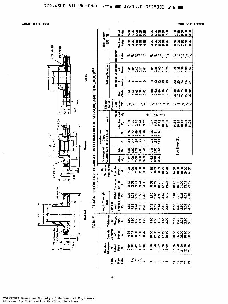
Orifice flange sizes are indicated by the nominal pipe size to which they are attached. Only those listed in Tables 1 through 6 are considered standard.
5 MARKING
Flanges shall be marked as required in ASME B16.5. For welding neck flanges only, the bore diameter shall be marked.
1
COPYRIGHT American Society of Mechanical EngineersLicensed by Information Handling ServicesCOPYRIGHT American Society of Mechanical EngineersLicensed by Information Handling Services
STD-ASHE B]il=|-31:-ENGL 1l“l“lI=| - I]75"lI=|7l] |]5?“lE'=lB 3T“| -
ASME B1636-1996
ORIFICE FLANGESClasses 300, 400, 600, 900, 1500, and 2500
1 SCOPE
1.1 General
This Standard covers anges (similar to those coveredin ASME Bl6.5) that have ori ce pressure diffentialconnections. Coverage is limited to the following:
(a) welding neck anges Classes 300, 400, 600, 900,1500, and 2500
(b) slip-on and threaded Class 300
1.2 References
1.2.1 Referenced Standards. Standards and spec-i cations adopted by reference in this Standard areshown in Annex B, which is part of this Standard. Itis not considered practical to identify the speci c editionof each standard and speci cation in the individualreferences. Instead, the speci c edition reference isidenti ed in Annex B. A ange manufactured in accord-ance with earlier editions of the referenced standardsand in all other respects conforming to this Standard willbe considered to be in accordance with this Standard.
1.2.2 Codes and Regulations. A ange usedunder the jurisdiction of the ASME Boiler and PressureVessel Code, the ASME Code for Pressure Piping, ora governmental regulation is subject to any limitationof that Code or regulation. This includes any maximumtemperature limitation, or rules governing the use ofa material at low temperature, or provisions for operationat pressure exceeding the pressure—temperature ratingsin this Standard.
1.3 Content
The requirements of this Standard include:(a) pressure ratings(b) marking(c) materials(d) dimensions(e) tolerances
1.4 Quality Systems
Non-mandatory requirements relating to the productmanufacturer’s Quality System Program are describedin Annex A.
2 PRESSURE-TEMPERATURE RATINGS
The pressure—temperature ratings, including all userecommendations and limitations, and the method ofrating given in ASME B16.5 apply to these anges.
3 MATERIAL
3.1 GeneralFlange materials shall meet all requirements of ASME
B 16.5.
3.2 Bolting
Material shall be in accordance with ASME Bl6.5.
3.3 Plugs
Pressure retaining plugs shall conform to ASMEBl6.l 1, unless otherwise agreed between purchaser andmanufacturer. Plug material shall be at least as corrosionresistant as the corresponding ange material.
4 SIZE
Ori ce ange sizes are indicated by the nominalpipe size to which they are attached. Only those listedin Tables 1 through 6 are considered standard.
5 MARKING
Flanges shall be marked as required in ASME B16.5.For welding neck anges only, the bore diameter shallbe marked.
ASME 616.36-1996
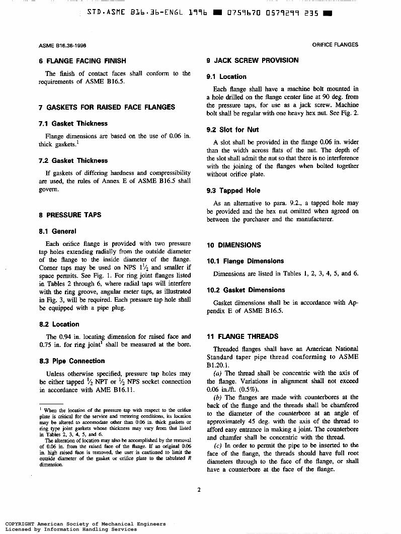
6 FLANGE FACING FINISH
The finish of contact faces shall conform to the requirements of ASME B16.5.
7 GASKETS FOR RAISED FACE FLANGES
7.1 Gasket Thickness
thick gaskets.' Flange dimensions are based on the use of 0.06 in.
7.2 Gasket Thickness
If gaskets of differing hardness and compressibility are used, the rules of Annex E of ASME B16.5 shall govern.
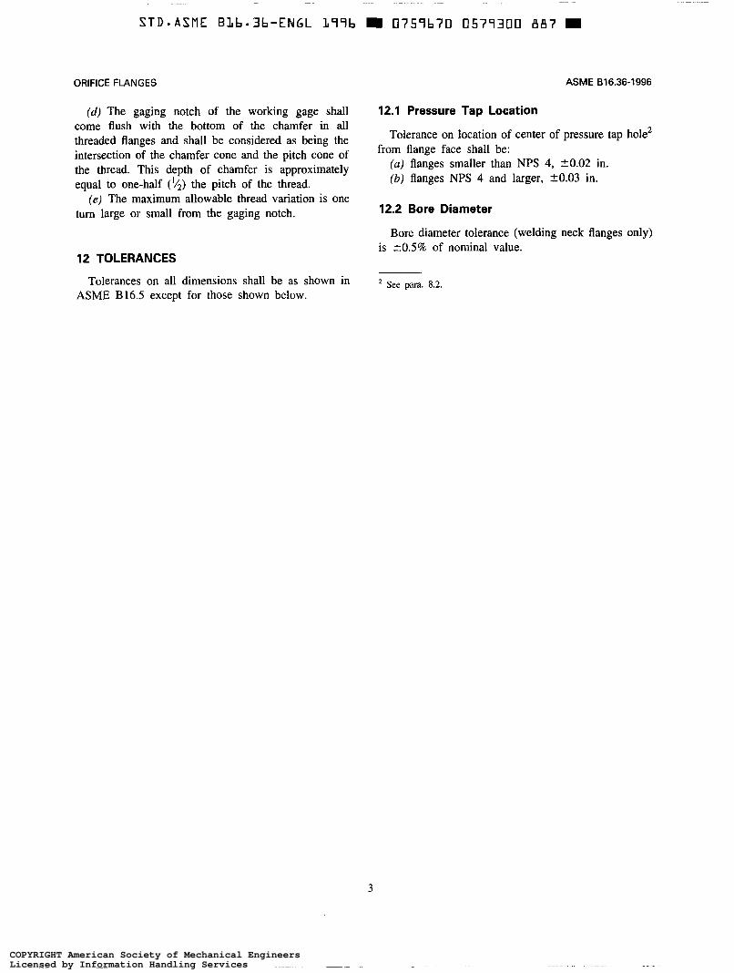
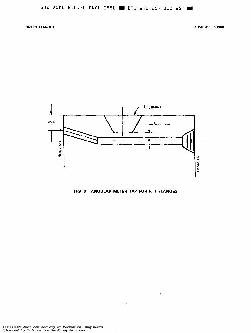
8 PRESSURE TAPS
8.1 General
Each orifice flange is provided with two pressure tap holes extending radially from the outside diameter of the flange to the inside diameter of the flange. Comer taps may be used on NPS 1p2 and smaller if space permits. See Fig. 1. For ring joint flanges listed in Tables 2 through 6, where radial taps will interfere with the ring groove, angular meter taps, as illustrated in Fig. 3, will be required. Each pressure tap hole shall be equipped with a pipe plug.
8.2 Location
The 0.94 in. locating dimension for raised face and 0.75 in. for ring joint' shall be measured at the bore.
8.3 Pipe Connection
Unless otherwise specified, pressure tap holes may be either tapped v2 NPT or v2 N P S socket connection in accordance with AME B16.11.
When the location of the pressure tap with respect to the orifice plate is critical for the service and metering conditions, its location may be altered to accomodate other than 0.06 in. thick gaskets or ring type joint gaskets whose thickness may vary from that listed in Tables 2, 3, 4, 5, and 6.
The alteration of location may also be accomplished by the removal of 0.06 in. from the raised face of the flange. If an original 0.06 in. high raised face is removed, the user is cautioned to limit the outside. diameter of the gasket or orifice plate to the tabulated R dimension.
ORIFICE FLANGES
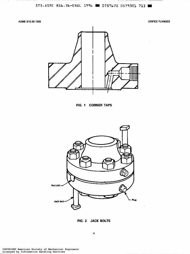
9 JACK SCREW PROVISION
9.1 Location
Each flange shail have a machine bolt mounted in a hole drilled on the flange center line at 90 deg. from the pressure taps, for use as a jack screw. Machine bolt shall be regular with one heavy hex nut. See Fig. 2.
9.2 Slot for Nut
A slot shall be provided in the flange 0.06 in. wider than the width across flats of the nut. The depth of the slot shall admit the nut so that there is no interference with the joining of the flanges when bolted together without orifice plate.
9.3 Tapped Hole
As an alternative to para. 9.2., a tapped hole may be provided and the hex nut omitted when agreed on between the purchaser and the manufacturer.
10 DIMENSIONS
10.1 Flange Dimensions
Dimensions are listed in Tables 1, 2, 3, 4, 5, and 6.
10.2 Gasket Dimensions
Gasket dimensions shall be in accordance with Ap- pendix E of ASME B16.5.
11 FLANGE THREADS
Threaded flanges shall have an American National Standard taper pipe thread conforming to ASME B1.20.1.
(a) The thread shall be concentric with the axis of the flange. Variations in alignment shall not exceed 0.06 in./ft. (0.5%).
(b) The flanges are made with counterbores at the back of the flange and the threads shall be chamfered to the diameter of the counterbore at an angle of approximately 45 deg. with the axis of the thread to afford easy entrance in making a joint. The counterbore and chamfer shall be concentric with the thread.
(c) In order to permit the pipe to be inserted to the face of the flange, the threads should have full root diameters through to the face of the flange, or shall have a counterbore at the face of the flange.
2
COPYRIGHT American Society of Mechanical EngineersLicensed by Information Handling ServicesCOPYRIGHT American Society of Mechanical EngineersLicensed by Information Handling Services
L STD-ASME Bllb-3|:-ENGL L"l°Il= I EI?5“II=7EI I]57“lE"I'=l E35 -
ASME B16.36-1996
6 FLANGE FACING FINISH
The nish of contact faces shall conform to therequirements of ASME Bl6.S.
7 GASKETS FOR RAISED FACE FLANGES
7.1 Gasket Thickness
Flange dimensions are based on the use of 0.06 in.thick gaskets}
7.2 Gasket ThicknessIf gaskets of differing hardness and compressibility
are used, the rules of Annex E of ASME Bl6.5 shallgovern.
8 PRESSURE TAPS
8.1 GeneralEach ori ce ange is provided with two pressure
tap holes extending radially from the outside diameterof the ange to the inside diameter of the ange.Comer taps may be used on NPS 11/2 and smaller ifspace permits. See Fig. 1. For ring joint anges listedin Tables 2 through 6, where radial taps will interferewith the ring groove, angular meter taps, as illustratedin Fig. 3, will be required. Each pressure tap hole shallbe equipped with a pipe plug.
8.2 LocationThe 0.94 in. locating dimension for raised face and
0.75 in. for ring joint‘ shall be measured at the bore.
8.3 Pipe ConnectionUnless otherwise speci ed, pressure tap holes may
be either tapped ‘/2 NPT or 1/2 NPS socket connectionin accordance with AME B16.11.
1 When the location of the pressure tap with respect to the ori ceplate is critical for the service and metering conditions, its locationmay be altered to accomodate other than 0.06 in. thick gaskets orring type joint gaskets whose thickness may vary from that listedin Tables 2, 3, 4, 5, and 6.
The alteration of location may also be accomplished by the removalof 0.06 in. from the raised face of the ange. If an original 0.06in. high raised face is removed, the user is cautioned to limit theoutside diameter of the gasket or ori ce plate to the tabulated Rdimension.
ORIFICE FLANGES
9 JACK SCREW PROVISION
9.1 Location
Each ange shall have a machine bolt mounted ina hole drilled on the ange center line at 90 deg. fromthe pressure taps, for use as a jack screw. Machinebolt shall be regular with one heavy hex nut. See Fig. 2.
9.2 Slot for NutA slot shall be provided in the ange 0.06 in. wider
than the width across ats of the nut. The depth ofthe slot shall admit the nut so that there is no interferencewith the joining of the anges when bolted togetherwithout ori ce plate.
9.3 Tapped HoleAs an altemative to para. 9.2., a tapped hole may
be provided and the hex nut omitted when agreed onbetween the purchaser and the manufacturer.
10 DIMENSIONS
10.1 Flange DimensionsDimensions are listed in Tables 1, 2, 3, 4, 5, and 6.
10.2 Gasket Dimensions
Gasket dimensions shall be in accordance with Ap-pendix E of ASME B16.5. A
11 FLANGE THREADS
Threaded anges shall have an American NationalStandard taper pipe thread conforming to ASMEB1.20.l.
(a) The thread shall be concentric with the axis ofthe ange. Variations in alignment shall not exceed0.06 in./ft. (0.5%).
(b) The anges are made with counterbores at theback of the ange and the threads shall be chamferedto the diameter of the counterbore at an angle ofapproximately 45 deg. with the axis of the thread toafford easy entrance in making a joint. The counterboreand chamfer shall be concentric with the thread.
(c) In order to permit the pipe to be inserted to theface of the ange, the threads should have full rootdiameters through to the face of the ange, or shallhave a counterbore at the face of the ange.
ORIFICE FLANGES
(d) The gaging notch of the working gage shall come flush with the bottom of the chamfer in all threaded flanges and shall be considered as being the intersection of the chamfer cone and the pitch cone of the thread. This depth of chamfer is approximately equal to one-half ('I2) the pitch of the thread.
(e) The maximum allowable thread variation is one turn large or small from the gaging notch.
12 TOLERANCES
Tolerances on all dimensions shall be as shown in ASME B16.5 except for those shown below.
ASME 816.36-1996
12.1 Pressure Tap Location
from flange face shall be: Tolerance on location of center of pressure tap hole'
(a) flanges smaller than NPS 4, 20.02 in. (b) flanges NPS 4 and larger, 20.03 in.
12.2 Bore Diameter
Bore diameter tolerance (welding neck flanges only) is + O S % of nominal value.
* See para. 8.2.
3
COPYRIGHT American Society of Mechanical EngineersLicensed by Information Handling ServicesCOPYRIGHT American Society of Mechanical EngineersLicensed by Information Handling Services
STD-ASHE B1lI=-3|;-ENGL 1|'1'=lI= - [l75“Il=?U El5?“IElIJl] BB? _
ORIFICE FLANGES
(d) The gaging notch of the working gage shallcome ush with the bottom of the chamfer in allthreaded anges and shall be considered as being theintersection of the chamfer cone and the pitch cone ofthe thread. This depth of chamfer is approximatelyequal to one-half (I/2) the pitch of the thread.
(e) The maximum allowable thread variation is onetum large or small from the gaging notch.
12 TOLERANCES
Tolerances on all dimensions shall be as shown inASME Bl6.5 except for those shown below.
ASME B16.36-1996
12.1 Pressure Tap Location
Tolerance on location of center of pressure tap holezfrom ange face shall be:
(a) anges smaller than NPS 4, $0.02 in.(b) anges NPS 4 and larger, $0.03 in.
12.2 Bore Diameter
Bore diameter tolerance (welding neck anges only)is i0.5% of nominal value.
2 See para. 8.2.
ASME 816.36-1996 ORIFICE FLANGES
FIG. 1 CORNER TAPS
FIG. 2 JACK BOLTS
4
COPYRIGHT American Society of Mechanical EngineersLicensed by Information Handling ServicesCOPYRIGHT American Society of Mechanical EngineersLicensed by Information Handling Services
STD-ASHE B1|I=-Ell:-ENGL ]r°l'=lb I El?5‘=ll=?[l I]5?'=lElEI]l 7L3 I
ASME B16 36 1996 ORIFICE FLANGES
Z /
//,
V4.
Nut slot
Jock bolt
FIG. 1 CORNER TAPS
§-I\_4
&-r\_/
2-1‘trer
‘Lis-"’
iI I (Q
V
FIG. 2 JACK BOLTS
4
i ir,if‘‘i all 55$?-i‘-1~—/
~_¢"1
PI
STD-ASME BLb.3b-ENGL L99b 0757b70 0577302 b5T
ASME 816.36-1996 ORIFICE FLANGES
FIG. 3 ANGULAR METER TAP FOR RTJ FLANGES
5
COPYRIGHT American Society of Mechanical EngineersLicensed by Information Handling ServicesCOPYRIGHT American Society of Mechanical EngineersLicensed by Information Handling Services
STD-ASME B].l=-3l=-ENGL 1.=l'=l'a — l]?5=lb?EI lIl5?=lEI[lE l=5T —
ORIFICE FLANGES ASME erase-1996
Fangebore
-l /—Ring groove
I‘ I "3/4 l | [3/16 in. min.
,__ T-
FIG. 3 ANGULAR METER TAP FOR RTJ FLANGES
5
FangeO.D
Out
side
X
amet
er
of
Rai
sed
Face
R 2.00
2.
88
3.62
4.
12
5.00
6.19
8.
50
10.6
2 12
.75
15.0
0
16.2
5 18
.50
21.0
0 23
.00
27.2
5
Out
side
D
iam
eter
of
fla
nge
O
4.88
6.
12
6.50
7.
50
8.25
10.0
0 12
.50
15.0
0 17
.50
20.5
0
23.0
0 25
.50
28.0
0 30
.50
36.0
0
Dia
met
er of
E
ount
erbo
re C
ount
erbo
re
Dep
th
(Fro
m F
ace)
rh
ickn
ess
of
Flan
ge,
Min
. C
1.50
1.
50
1.50
1.
50
1.50
1.50
1.
50
1.62
1.
88
2.00
2.12
2.
25
2.38
2.
50
2.75
Slip
-On
and
Thre
aded
Y
2
1.88
1.
88
1.94
2.
00
2.06
2.12
2.
12
2.44
2.
62
2.88
3.00
3.
25
3.50
3.
75
4.19
i(5L
Iach
ine
Bol
ts
4.50
4.
75
4.50
4.
75
4.75
4.75
4.
75
5.00
5.
75
6.25
6.50
7.
00
7.25
7.
50
8.25
(611
Stu
d B
ob
5.00
5.
25
5.00
5.
25
5.25
5.25
5.
25
5.75
6.
50
7.00
7.25
8.00
y,
8.50
7.75
g
9.50
7
Mel
d Ue
ck
BI - - I- P) c. g $
0
Pres
sure
C
on-
nect
ion
77
;I4
14
k4
14
18
l12
12
5;
12
'/2 '/2 ?;
12
'/2
1 3 ;I2
1 1
0.W
J I
0.06
z
GI
I- TA
BLE
1
CLA
SS 3
00 O
RIF
ICE
FLA
NG
ES, W
ELD
ING
NEC
K, S
LIP-
ON
, AN
D T
HR
EAD
ED3P
ter
of
I Hub
D
iam
eter
Ie
ginn
ing
of
Cha
mfe
r (W
.N.)
A
1.32
1.
90
2.38
2.
88
3.50
4.50
6.
63
8.63
10
.75
12.7
5
14.0
0 16
.00
18.0
0 20
.00
24.0
0
I+ n
n
0-
Dri
llin -
lum
bei
of
Hol
es
4 4 8 8 8 8 12
12
16
16
20
20
24
24
24
- ie
mpl
ate
T-T
Bac
k Fa
ce
-
G
0.75
0.
72
0.69
0.
56
0.56
0.56
0.31
0.
44
-
- -
lip-O
r B2
1.36
1.
95
2.44
2.
94
3.57
4.57
6.
72
8.72
10
.88
12.8
8
14.1
4 16
.16
18.1
8 20
.20
24.2
5
-
-
Bol
t C
ircle
3.50
4.
50
5.00
5.
88
6.62
7.88
10
.62
13.0
0 15
.25
17.7
5
20.2
5 22
.50
24.7
5 27
.00
32.0
0
-
o!
Nom
- in
al
Pip
e S
ize 1 2 1 '12
2 '/2
3
Wel
d N
eck
Y1
biam
eter
of
Hub
X 2.12
2.
75
3.31
3.
94
4.62
5.75
8.
12
10.2
5 12
.62
14.7
5
16.7
5 19
.00
21.0
0 23
.12
27.6
2
3.25
3.
38
3.38
3.
50
3.50
3.62
3.
94
4.38
4.
62
5.12
5.62
5.
75
6.25
6.
38
6.62
0.69
0.
81
0.69
0.
81
0.81
4 6 8 10
12
0.81
0.
88
1 .oo
1.12
1.
25
1.25
1.
38
1.38
1.
38
1.62
14
16
18
20
24
See
Not
e (8
).
COPYRIGHT American Society of Mechanical EngineersLicensed by Information Handling ServicesCOPYRIGHT American Society of Mechanical EngineersLicensed by Information Handling Services
SEGWFEmWRO6991_6361BEWA
H568686“KsgCOR86$56£6$6QqmmgCO6m dCD6
adSSggO2adEdCO6mm:WW4‘“KiM“:8_€mm:8*
N\_____\__q\__m\___
SQ"$QMX"gmQMQM
Nw___asms“SmN__mgN_‘_8__mgFwdEdEdQQQEdWQQ
UNCONN¢NCORN_‘N@h_QNQNQqg8@N_ON2_|_K_:_232NFOqg2N2“:QQQNQN06Q$6QO3QCg?Qgm“
N\__N\_N\_Q_N\_Q_N\_N\FN\_N\_Q\MQ\_Q\_{F‘\_
S99Nw9UI‘
MMNQN33:226?:_:QQNP32NF“NR6BeRx“QQNSN8__©M_F
56$6S6$6QQON502.6
Q_N$38___:3ms8;5*;S: Ag£02gm
mg$6mm:EN“QQNQMNQQ__Oq__
SWOP
mgQ56Mg?MQMO06HENQQF;__
8_§89Oqg8_2Oq:R2RA:MQW“$6CW3‘HidQ2WM“QqFNqF
NQNNN___MNOqKQqggm:m :NqQNOFNF“EBNQ€iq56MENN__N
$6ad£6MED$6@PdNq8636NQMadhadQM“22"ad
Q__Q£8SMadCO6QQNNQNgdadad8dOQNVG;m®___WW;
Q5“9”“QQNmgN__NCONQQFNQF8___3;°__m__O5O38__OQF
Oq86MOQQN8_mNQQMNOQQN9____:_OqOqg8_Q_MqSN86ad86
MNBNOQMNOqKOWEqgCOMPgNQ2“EdMP6gmNPdNQMQQNCON
_&8223Q2MQQMNQ;?
EON___3W
ugom
n o
._______:_z3
:_°___*0
83:°_“____°
°____:9_n_3__.__
N
tQQ
3=8__£§___832___°_A___m
‘£255__2O____Ia£532____O°ED;
Q
M
__°8:
_g‘gm
=2__m__._.______8_9________°____28__$________g _.5is
20e8____QO ta-“_
EOE
20____z_____O°BBgsla
Q___’__;_8::‘O__._______O=:_:_O
*0
X
_____o_z2.;
"L__'____2_;
E.82.:*0_:O_:___°_____w3_82__I_n__°______,_
°________2n| l|=U5_2_____.2830__:2__a_n_agsgna___Q3830________i__°_______ab‘:
U£2
O5:5
Q8:
:5:__n_
_
§Dm_n_<m__“_E_DZ<_Z°_n__._M_v_UuZ0Z_n___m__s$62‘Q85ii-___F{'2‘$3
°8DQ8
86
36
"_._\_l\.FaEN“||‘,>h_\_LQ
____§_~\_‘R\'UN_______t
(IENUEEOO2"WWSUPWJE:
i_u_‘i~w|'__i_Ed?itli6361%ll‘Fl“-A_\_l\~"R__|lhh|'|||__IIllI___"llum|_|‘____|.||">__
\II\
‘iI_\L‘_,.N‘_'\\\b‘
ll‘\UQw\.U___*
TEL_:_EZN\__EmaX_?___L
:2N:i‘Eso:8:
E______t‘\8_________%t
GE
NE
RA
L N
OTE
: Dim
ensi
ons
are
in in
ches
.
NO
TES
: (1
) O
ther
NPT
siz
es m
ay b
e fu
rnis
hed
if re
quire
d.
(2)
For s
lip-o
n an
d th
read
ed fl
ange
s, v
erify
that
77d
rilli
ng e
xten
ds to
insi
de d
iam
eter
of p
ipe
afte
r ass
embl
y an
d is
free
from
bur
rs.
(3)
Wel
d ne
ck fl
ange
s N
PS
3 a
nd s
mal
ler
are
iden
tical
to C
lass
600
flan
ges
and
may
be
so m
arke
d.
(4)
All
othe
r di
men
sion
s ar
e in
acc
orda
nce
with
AS
ME
816
.5.
(5)
Bolt
leng
ths
incl
ude
allo
wan
ce fo
r or
ifice
and
gas
ket t
hick
ness
of 0
.25
in. f
or N
PS
1-1
2 an
d 0.
38 in
. for
NPS
14-
24.
(6)
In c
onfo
rman
ce w
ith A
SM
E 8
16.5
, stu
d bo
lt le
ngth
s do
not
incl
ude
poin
t he
ight
s.
(7)
Bor
e di
amet
er o
f wel
d ne
ck R
ange
s is
to b
e sp
ecifi
ed b
y th
e pu
rcha
ser.
(8
) Th
read
ed fl
ange
s ar
e fu
rnis
hed
in N
PS 1
-8 o
nly.
E 2 m
VI
-I U * VI x
m
m
P
U- w 71
m
U-
D z m
rn
COPYRIGHT American Society of Mechanical EngineersLicensed by Information Handling ServicesCOPYRIGHT American Society of Mechanical EngineersLicensed by Information Handling Services
69946361BEMSASEGMFEmWHO
_>_COml?mmzC_B __'___aENgmgc_g_u8E___av
_$§_8__QQ55nQ£OQQMB9Egag:V_U®___E0;u_O_2QE_w__U20mE
_B_'_mmB_EOQmi___UC_HOEOn_m___“m5_:3E5_m_w_mM22FE;85E_£COOC_A8
_qN\:mlz_2_____mgU5N_l__w_“__,_H2Emg*0$gv_O____H“Bag“CUQUELOhe8C__U_>>O__@%_1__QC_M£m5_~_OmEV
dd;w_>_m<PE;8___%__8gEENQ_o_w$E_U550__<E>
5
______9___NE8On$5EN895:O8$20OH_8_E%_pa__Q__NEWEaMmmz$95:V3222>
625E0:GP;EU5>_n_____$g5:3MiaB‘_w_mE~_°0°559gcgxwmE__%t“gta___mv>_gm:_w_‘_um_ug___L_HENColgmatAN“
U___JUU__hm_8___W______e3>NEgumIE2__U£OA:
“E02
$205EmgWCO_WCQE_QE02émmzmw_
77 d
rill
mus
t be
PiiR
in(m
d Da
tdl
Orifh
Q
lm
Rabd
Fm
Rh
w Ty
poJo
lrn
-MY
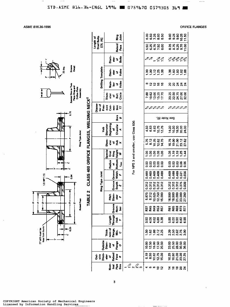
TABL
E 2
CLA
SS
400
OR
IFIC
E FL
ANG
ES,
WEL
DIN
G
NEC
K2 I I
Ring
Ty
pe
Join
t
Thick
- ne
ss
of
Leng
th
l-l-l
Piich
1
flang
e,
Thro
ugh
Groo
ve
Diam
- M
in.
Hub
Num
- et
er
C Y
ber
P
Ring
Ty
pe
Join
t Hu
b Th
ick-
Spec
ial
Diam
- Di
amet
er
ness
of
Le
ngth
Pi
ich
Radi
us
Oval
eter
Be
ginn
ing
flang
e,
Thro
ugh
Groo
ve
Diam
- Gr
oove
Gr
oove
at
Ri
ng
of
of
Min
. Hu
b Nu
m-
eter
De
pth
Wid
th
Botto
m
Heig
ht
Hub
Cham
fer
Bore
C
Y be
r P
E F
rma
W
X A
B
Groo
ve L De
pth
E
1 Rad
ius
e?I
I I
Hub
Diam
- Di
amet
er
eter
Be
ginn
ing
l-L
of
of
Hub
Cham
fer
Bore
X
A B
Xam
e te
r of
Pr
es-
sure
Co
n-
nec-
tio
n 77
Drilli
ng
Tem
plat
e
Leng
th
of
Stud
Bo
lts
W).
(411
Diam
- et
er
of
Bolt
Num
- be
r of
Ho
les
03
inal
Pi
pe
Size
eter
of
Ho
les
1 1'/2
2 2'/2
3
For
NPS
3 an
d sm
aller
,use
Clas
s 80
0.
4 6.1
9 10
.00
1.50
3.50
R37
5.87
5 0.
312
0.46
9 0.0
3 6
8.50
12.5
0 1.6
2 4.0
6 R4
5 8.
312
0.31
2 0.
469
0.03
8 10
.62
15.0
0 1.8
8 4.6
2 R4
9 10
.625
0.
312
0.46
9 0.0
3 10
12
.75
17.5
0 2.1
2 4.8
8 R5
3 12
.750
0.
312
0.46
9 0.0
3 12
15
.00
20.5
0 2.2
5 5.3
8 R5
7 15
.000
0.
312
0.46
9 0.0
3
14
16.2
5 23
.00
2.39
5.88
R61
16.5
00
0.31
2 0.
469
0.03
16
18.5
0 25
.50
2.50
6.00
R65
18.5
00
0.31
2 0.
469
0.03
18
21.0
0 28
.00
2.62
6.50
R69
21.0
00
0.31
2 0.
469
0.03
20
23.0
0 30
.50
2.75
6.62
R73
23.0
00
0.37
5 0.
531
0.06
24
27.2
5 36
.00
3.00
6.88
R77
27.2
50
0.93
8 0.
656
0.06
1.06
5.75
4.50
1.06
8.12
6.63
1.06
10.2
5 8.6
3 1.0
6 12
.62
10.7
5 1.0
6 14
.75
12.7
5
1.06
16.7
5 14
.00
1.19
19.0
0 16
.00
1.19
21.0
0 18
.00
1.25
23.1
2 20
.00
1.44
27.6
2 24
.00
s 0 5 z 8 v) - 1
7.88
10.6
2 13
.00
15.2
5 17
.75
20.2
5 22
.50
24.7
5 27
.00
32.0
0
8 12
12
16
16
20
20
24
24
24
1.00
1.00
1.12
1.25
1.38
1.38
1.50
1.50
1.62
1.88
5.50
6.00
6.25
6.50
6.75
7.25
7.50
8.00
8.00
8.50
8.25
8.75
9.25
9.75
11.0
0
9.00
9.25
9.50
10.2
5 g
11.5
0 5 R g E
COPYRIGHT American Society of Mechanical EngineersLicensed by Information Handling ServicesCOPYRIGHT American Society of Mechanical EngineersLicensed by Information Handling Services
SEGNMFEmWRO69946361BEMSA
8::H36mgCO6S“OQQ8R$6CO6 mN_O_
OQ___FDR“DNQEEGmgCgasmidmg8d
__\m_N\__xi$__#\___m\___P
ehQ5
H5;cm:mgmgmgé2: mg__“Q__°°_?
€@CONMHQNCONNQN@N__‘NONHENNAN@N_ON2ESP2$2gOqgN__NQ2QQQN
Q_N\_XN\_Q_N\_Q_N\_N\_N
S39NO\'8G
QQVNOqgCqgOQ2Dq:WNNF@§d__Q:NW68___
NQBNgOO___NOqg_'_=|_Q_M5:NQNF£9dMK6
s___msm __Q:OH:8F8F8__8___0°.F
862;M668686gdmugM568625
@@©‘QEHHOQ21“@©Q_O®©_‘_O@©§_Q@219Q@QdQ36®©¢_D
82EhdN36N56gN56NFQONgdN56N56
252OOO_KOOQEOOQ2COCA:$:_®N©_Q_N5“MKQM Ran
NFCMRI$9“m©E__$_REMWIGS‘__§_59*
$6ND6H56CO6QM““*2$6NQQQQQOnm
CO6m dNQNOQN2"“QNNNFN®W___N©___8__
8836%OQWNEa9:“8_ON3:OqSNFQQS
MNSN8_MN8_Z$2gm:QC“__“KN__NQ2OmdQ_6
QNQN223N__2®QQ
dew820Um:___m__mEmUsMw _Z‘_°"_
MNN\_?
?
u___°__
8:
£0“*0H30_E___°
2_°___33
02°:225
EON
BU:HUD‘O
i‘Eggi__________,_i
__U“U_Eg
=3_E_3:53“‘O gs _H____"_i__om_____i
8_w_%_°___m_______ _
_______“_n_h:9:_:___‘goBalg;EB“
NQXi23__£_E“___Ue____“___E°___Eog£3;___=__g_3%‘E5:_________
S3
u________m__masE6m__=___E___§___5233as__80EIE____g__w3__w___“_______
________“_NE3
A>O
_c_____
O__m_=_“_
*0as_EU_°
t8:Sso
8::D2830IEIE
“____O__D__>____n___EO
“E:LEiO>°°__wiO>OO_ui‘ERGO.>O°__w _-SO______'_a_____“_
E“go
352:‘IE0:
K
____§_‘Eu_§2MT
~_
Nv_UmZ0Z_D___u>>WWUZ<J"_m_o_"___“_o2;WWSUNW._ <___
>15____°_____>__________8-L‘S-i5-K_§_O___________8.:sh52°32$26 VadBN6%
\>\\~Flti‘
\Q
i\_._\__‘_AmiE“‘\\'__\>> ‘i\a_v‘\.\_._>FMm_
____:2N:QE3Es.at
3“___E___i_:_
_U $_‘lMH'_|'_Ui
GE
NE
RA
L N
OTE
: Dim
ensi
ons
are
in in
ches
.
NO
TES
: (1
) O
ther
NP
T si
zes
may
be
furn
ishe
d if
requ
ired.
(2
) A
ll ot
her
dim
ensi
ons
are
in a
ccor
danc
e w
ith A
SM
E B
16.5
. (3
) In
con
form
ance
with
AS
ME
B16
.5, s
tud
bolt
leng
ths
do n
ot in
clud
e po
int h
eigh
ts.
(4)
Bol
t len
gths
for
rais
ed fa
ce fl
ange
s in
clud
e al
low
ance
for
orifi
ce a
nd g
aske
t thi
ckne
ss o
f 0.2
5 in
. for
NP
S 4
-12
and
0.38
in. f
or
NP
S 1
4-24
. B
olt l
engt
hs fo
r rin
g ty
pe jo
int f
lang
es in
clud
e al
low
ance
of
0.62
in. f
or N
PS
4-1
0,
0.75
in. f
or N
PS
12-
18, a
nd 0
.88
in. f
or N
PS
20.
(5
) B
ore
is to
be
spec
ified
by
the
purc
hase
r.
(6)
Rin
g jo
int
flang
e in
NP
S 2
4 w
ill r
equi
re a
n an
gula
r met
er ta
p as
sho
wn
in F
ig. 3
.
W
0-
I m
GI
=I
0
0
Ln
4
d
W 0
0-
m
-I
u-
1
D
Ln m
COPYRIGHT American Society of Mechanical EngineersLicensed by Information Handling ServicesCOPYRIGHT American Society of Mechanical EngineersLicensed by Information Handling Services
699___'6361BEMSASEGNMFEmFmO
_m_m_“_E___>>9_mWMasL205E___m_;CM25g_____;QNwmzEggzEam__EE
___32_U5Q$5>5_vg__UgWOn22BowE
_°NW125_C_
$6Ea_m__'N_w_“_zhe_____mhd67¢wlz__e_c_NM;*085>>°__NQ_U:_UEWgcg“E2atmE__h°*Q__~m5_“Em_§l_‘__mm:/_he_c_“MdE5N__|_‘wmz__°“__C_mwd3$2_v_U_£gigENgiro__£8___g6___w%J_UEmDmCN=83B298*M___ag_tom5
_&_,_Q2_E_°n_%___U___HOEcug_m5_:2gm_m_w__mm_s_m<5_>>QOCNE__2_C°UE5
_m_w_mw_>_m<ts8__aEO8_mEP5W___°_m___QE%65°__<E
_€______g__u_uU__bW____‘__:2>9:W@N_MPLZ$50E
“E02
_$___U___EU5W___°_m___QE_QE02é zmo
l-----
----4
0.
;5
8p&
l on
e or
Tw
o G
-
RaM
Fw
r Ri
ng T
YPO
Join
t
Piiw
R
ing
and
orifk
a Pl
ate
Asse
mbl
y
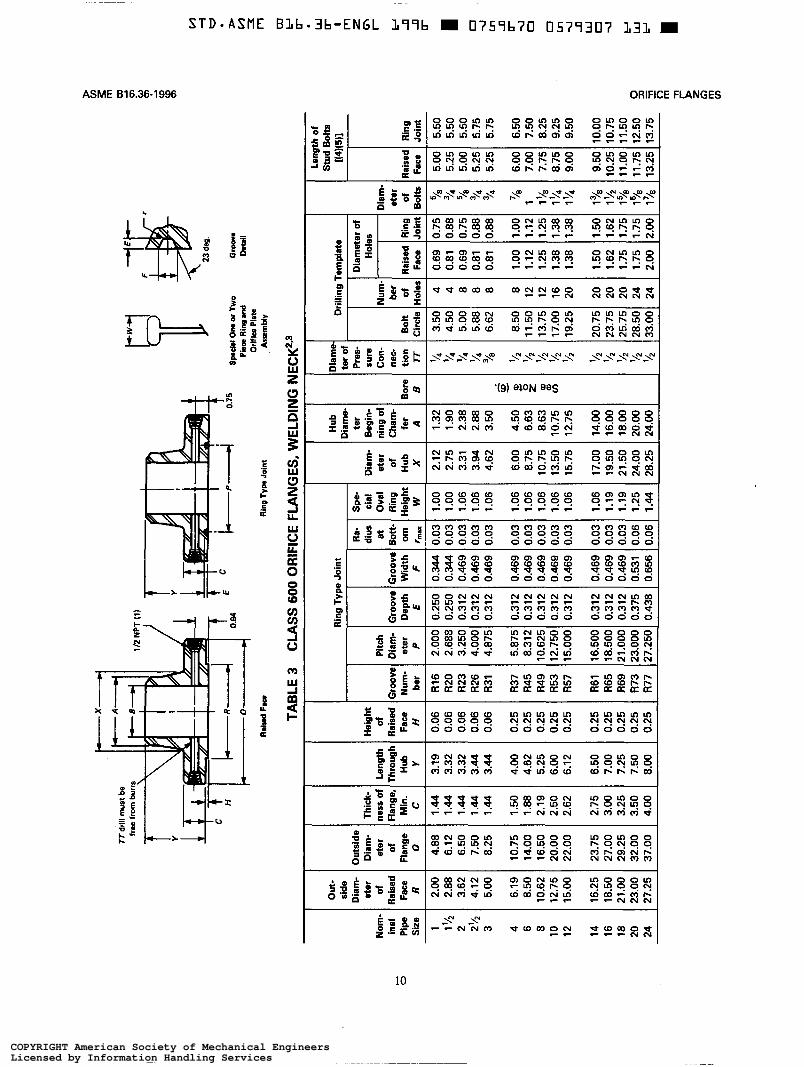
TABL
E 3
CLA
SS
600
OR
IFIC
E FL
ANG
ES,
WEL
DIN
G
NEC
K2r3
- Bo
re
I3 g E e t VI
-
T T
T T
Leng
th
of
Stud
Bo
lts
[(4)(5
11
liam
e :e
r of
Nom
- in
al
E,
Pipe
Si
ze
OUt-
side
Diam
- et
er
of
Zaise
d Fa
ce
R
Duts
ide
Diam
- et
er
of
Flan
ge
0
rhick
- les
s of
Ia
nge,
M
in.
c
1 Leng
th
rhro
ugh
Hub Y
of
Raise
d Fa
ce
H
iroov
e
ber
1 2.0
0 4.8
8 1.
44
3.19
0.0
6 R1
6 1 '
/2 2.8
8 6.1
2 1.4
4 3.3
2 0.0
6 R2
0 2
3.82
6.50
1.44
3.32
0.06
R23
2'/*
4.12
7.50
1.44
3.44
0.06
R26
3 5.0
0 8.2
5 1.4
4 3.4
4 0.0
6 R3
1
4 6.1
9 10
.75
1.50
4.00
0.25
R37
6 8.5
0 14
.00
1.88
4.62
0.25
R45
8 10
.62
16.5
0 2.1
9 5.2
5 0.2
5 R4
9 10
12
.75
20.0
0 2.5
0 6.0
0 0.2
5 R5
3 12
15
.00
22.0
0 2.6
2 6.1
2 0.2
5 R5
7
14
16.2
5 23
.75
2.75
6.50
0.25
R61
16
18.5
0 27
.00
3.00
7.00
0.25
R65
18
21.0
0 29
.25
3.25
7.25
0.25
R69
20
23.0
0 32
.00
3.50
7.50
0.25
R73
24
27.2
5 37
.00
4.00
8.00
0.25
R77
Ring
Ty
l
Pitc
h Di
am-
Groo
ve
eter
De
pth
P E
2.00
0 0.
250
2.68
8 0.
250
3.25
0 0.
312
4.00
0 0.
312
4.87
5 0.
312
sroov
e W
idth
F
Ra-
dius
at
Bo
tt-
om
rtttu
cial
Oval
Ring
ie
ight
W
t
eter
of
Hu
b X
Hub
Xam
e-
ter
Begi
n-
ling
of
Cham
- fe
r A
0.34
4 0.0
3 1.0
0 2.1
2 1.3
2 0.
344
0.03
1.00
2.75
1.90
0.
469
0.03
1.06
3.31
2.38
0.46
9 0.0
3 1.0
6 3.9
4 2.8
8 0.
469
0.03
1.06
4.62
3.50
6.87
5 0.
312
0.46
9 0.0
3 1.0
6 6.0
0 4.5
0 8.
312
0.31
2 0.
469
0.03
1.06
8.75
6.63
10.6
25
0.31
2 0.
469
0.03
1.06
10.7
5 8.6
3 12
.750
0.
312
0.46
9 0.0
3 1.0
6 13
.50
10.7
5 15
.000
0.
312
0.46
9 0.0
3 1.0
6 15
.75
12.7
5
16.5
00
0.31
2 0.
469
0.03
1.06
17.0
0 14
.00
18.5
00
0.31
2 0.
469
0.03
1.19
19.5
0 16
.00
!l.OOO
0.
312
0.46
9 0.0
3 1.1
9 21
.50
18.0
0 !3.
000
0.37
5 0.
531
0.06
1.25
24.0
0 20
.00
!7.25
0 0.
438
0.65
6 0.0
6 1.4
4 28
.25
24.0
0
Drilli
ng
Tem
plat
e
Diam
eter
of
Ho
les
Bolt
Circ
le
Iurn
, be
r of
lole
z
-T 4 8 8 8
I Pai
sed
Ring
Fa
ce
Join
1
3.50
4.50
5.00
5.88
6.62
0.69
0.75
0.81
0.88
0.69
0.75
0.81
0.88
0.81
0.88
8.50
8 1.0
0 1.0
0 11
.50
12
1.12
1.12
13.7
5 12
1.2
5 1.2
5 17
.00
16
1.38
1.38
19.2
5 20
1.3
8 1.3
8
20.7
5 23
.75
25.7
5 28
.50
33.0
0
20
20
20
24
24
-
1.50
1.50
1.62
1.62
1.75
1.75
1.75
1.75
2.00
2.00
sure
Co
n-
eter
of
I
tion TT
la
isec
Ring
Jo
int
I
5.00
5.25
5.00
5.25
5.25
6.00
7.00
7.75
8.75
9.00
9.50
10.2
5 Il.0
0 11
.75
13.2
5
6.50
7.50
8.25
9.25
9.50
10.0
0 10
.75
11.5
0 12
.50
g 13
.75
3 8 c x El
COPYRIGHT American Society of Mechanical EngineersLicensed by Information Handling ServicesCOPYRIGHT American Society of Mechanical EngineersLicensed by Information Handling Services
SEGWFEmWRO%91cw361BEWA
R___U__8“?%_:QH28_Q__86£6mgSN86nkd“K6OWEOD_mCD6
gQ“____Sq:an:gmOQQRd£5HEN86£6gmCgmgCOM
w\h_$__QtN\____MfQ\_____\__SF
{EQ"_\m__\mQMgm
OQNgFMN;NQF8PM2mgmN___N_____OQFNW6QQO£6£6mg
CON___§_____NQF9:mgmm;MN;N___2:5656®©_¢EdGQQ
¢N¢NQNONg
82OQMWNggm@F_HK
ON322OQ:N__gN__0%:WadQNQWWww_mQCgQ“EdQHEM
N\__QFN\_N\_N\__~\__N\_Q_Q_Q_QMV\_Q\____\_‘\_
Se9NO19m(
OQQNOQONOQ9OqgCg:MKNPBRA:ma$6Cw?H54“MadmugQ®___$M___
gQO_QNS_PNH52Oqt@N____”__Owemh_2$6QQQ$6#56__M_MMNNNFM
3;mgm:2;weQ3Q2wewem°___mgwem°___Q3o°___
CO686gdM56M66M06MadM66N66MQQM06Mad86Mg86
$2:56$2“Qg_OQ368;$€_O_§____QQYO@910gg@$_Oas¢g_OS56
Qgd£2N86N56N56
ENHNOOQMNOOQ__NQQQ225.2
ghdN__M_ON56N36N56
OOQ9OD§N__ax:N8622
N56N56N56OWNS$2
@Bq_‘02:‘OgdMWWQNCOQN
“NEMRIGQI_§___$_REMDIQ3“__§_59‘atDNEMNIONEQFm
£6BN6MNQDMD£6mad£6$6$6@qQQQOQQOQ06Q0686
gd8‘was8‘86NPdO06mgNQ12:‘3:"36NQM"N:26
HadOmdMNMCOMMR“NQNOm_N2“wD___QQF3;S“;S‘;3___3___
OOSMOQNNMNQNOQNNQBMNQQNNOQON8gOQ:$2:QNQSK862686
£_RDQMNOQFNH52@N_©_Cg?MEN?NQOFA5626CO6NS‘NQMHQWNCON
¢NON2_232M“myQMNaNN\_?_
g______EE
OOH‘
8_°D
__:_:_*0
at
“___O__“CE
all
W20:225
____:_g_*0=8
____=El
:_O___*0__3’E£ _
an|_______z
_§E_._________:9_____5go“Ea“_°_€__”__
tCO:'3:‘CODP5“‘QUE*0__$
N23
<__£_____w__u3m_________m£_
H0“'OEw_°________
V“_______338‘ENE
2“__m_°___“CEE6E9aim
ifE0.89“S2%‘ g
RWK__“____s‘EGOH86IE5:26962596‘Ego2°96‘aim__’__O__=__°m___H_“_
£8:3__s__q_8mug
E
“E2.g>___GE‘
I8:
>_______
U____s_
Q°Q_‘_"_
F5°
t“owl2%“:
8
___u_$____“______________D33
2____§°_____B
OED*6
35HE______
=50=85U82
m_~v_Um__’_UZ_O___m_>>_WmUZ<|_"_WU_“___"_o25WWSUMHJ <___>:E*’<_u_________;___EE8-13.‘
8-:‘SEOE‘EEa-E°E’ad________:__°_I_0wmgTl__
_u*|+U
___WQI
F
_:|IE:ElIf
_“\_
tEUM\“Fi,§'i
F
4!.
Etzg
L
MNQX
‘\A_I_‘
|_
ggED:0°:2356E6t
l
HV%
0_
GE
NE
RA
L N
OTE
: D
imen
sion
s ar
e in
inch
es.
NO
TES
: (1
) O
ther
NP
T si
zes
may
be
furn
ishe
d if
requ
ired.
(2) W
eldn
eck
flang
es N
PS
3 a
nd s
mal
ler
are
iden
tical
to C
lass
300
flan
ges
exce
pt fo
r bo
lting
and
may
be
use
d fo
r su
ch s
ervi
ce.
(3)
All
othe
r di
men
sion
s ar
e in
acc
orda
nce
with
AS
ME
816
.5.
(4)
Bol
t len
gths
for
rais
ed fa
ce fl
ange
s in
clud
e al
low
ance
for
orifi
ce a
nd g
aske
t thi
ckne
ss o
f 0.2
5 in
. for
NP
S 1
-12
and
0.38
in.
for
NP
S 1
4-24
. B
olt l
engt
hs fo
r rin
g ty
pe jo
int f
lang
es in
clud
e al
low
ance
of 0
.62
in. f
or N
PS
1-1
0, 0
.75
in. f
or N
PS
12-
18,
and
0.88
in
. for
NP
S 2
0.
(5)
In c
onfo
rman
ce w
ith A
SM
E B
16.5
, st
ud b
olt
leng
ths
do
not
incl
ude
poin
t he
ight
s.
(6)
Bor
e is
to b
e s
peci
fied
by
the
purc
hase
r.
(7)
Rin
g jo
int f
lang
e in
NP
S 2
4 w
ill r
equi
re a
n an
gula
r m
eter
tap
as s
how
n in
Fig
. 3.
v)
-I
W
W
U- I I
COPYRIGHT American Society of Mechanical EngineersLicensed by Information Handling ServicesCOPYRIGHT American Society of Mechanical EngineersLicensed by Information Handling Services
6994636-IBEMSASEGNMFEmFmO
_m_m_“_E___>>°_‘_MWMas__D“QC__a_Dm____w5P_=_g_____;‘NmmzE%r__£E2GCEE
___QWN___U__3QU5>3RE_Um__%OnOH290mQ
_mEm_2_ESQ%___OE“QCQtW£m5_=2Ea_m_o_m_m__>_w<___§>QUCMESEOQEE
ONW12__£E
mg ggigmmzhe_____mg_o_|_225_C_N2“PO§_g>O___wOBOE$mC_m_¥E_O_25gt5£m___m__=3_¢Nl:wmzLO*_C_andEaN__|FwmzLO‘_EmN_o*OWMUCXUEH“EggUCNDU_“____O__O*QOCN>>O__N0U___U____m%__gQUEU029‘_O*MF:mCQ_“_Om__E
_m_m__mm_2m<FE;QOCNu__DOOQ____EN%___O_mC@E_“_hm____6__<av
mWWWB_NUE__UEpa__Q___wEWEaWwlzgs:v_8C_u_g>E
_UU_>__mWEa__2ggma>NE35“C502L2E86WUCggm5
_u2_:g__UU___w___:Dhv2>GEMQNE__I _Z$50
A:
“E02
_§_2_____M5p_%_BE_n_M62émwzwo
lI
D cn m
Bor
e
Dia
m-
eter
of
P
ress
ure
Con
nec-
ti
on
B
TT
iid
riil
mus
t be
free
from
bu
rs
Y
TAB
LE 4
C
LAS
S 9
00 O
RIF
ICE
FLA
NG
ES, W
ELD
ING
NEC
K'
-
Dia
m-
eter
of
Hub
X
I
OU
t- si
de
Dia
m-
eter
of
R
aise
d Fa
ce
R -
-
5.00
6.19
8.50
10.62
12.75
15.00
16.25
18.50
21 .o
o 23.00
27.25 -
Len
gth
of
Stu
d B
ob
I(
3. (4
)l
Rai
sed
Rin
g I
Face
Jo
int
I R
ing
Typ
e Jo
int (
6)
Dri
llin
g T
emp
late
Dia
met
er
Hu
b
Dia
met
er
Beg
inni
ng
of
Cha
mfe
r A
I+ n
r
n
Len
gth
R
adiu
s Th
roug
h H;b
1 Gr oov] F- 1 1
IB;;; N
um
ber
Spe
cial
O
val
Rin
g H
eig
ht
W
No
mi-
na
l P
ipe
e
Siz
e
1 2
N -
1 Y2
2Y2 -
3 4 6 8 10
12
14
16
18
20
24 -
Flan
ge
For
NPS
2v2 an
d sm
alle
r, use
Cla
ss 1500.
~
6.50
7.50
8.25
9.50
10.00
10.75
I 1.50
12.00
13.75
14.75
Eg
5 2 fi m z v
)
-
8 8 12
12
16
20
20
20
20
20
20 -
-
6.00
7.00
7.75
9.00
9.50
10.25
11.00
11.50
13.00
14.00
17.50 -
0.469
0.469
0.469
0.469
0.469
0.469
0.656
0.656
0.781
0.781
1.062
0.03
0.03
0.03
0.03
0.03
0.03
0.06
0.06
0.06
0.06
0.09
1.06
1.06
1.06
1.06
1.06
1.06
1.31
1.44
1.56
1.56
1.88
5.00
6.25
9.25
11.75
14.50
16.50
17.75
20.00
22.25
24.50
29.50
3.50
4.50
6.63
8.63
10.75
12.75
14.00
16.00
18.00
20.00
24.00
7.50
9.25
12.50
15.50
18.50
21.00
22.00
24.25
27.00
29.50
35.50
1 .oo
1.25
1.25
1.50
1.50
1.50
1.62
1.75
2.00
2.12
2.62
I
COPYRIGHT American Society of Mechanical EngineersLicensed by Information Handling ServicesCOPYRIGHT American Society of Mechanical EngineersLicensed by Information Handling Services
SEGWFECHRO6991_6361BEWA
QQQ_|_g_E_@$_OO_N__OQ___gsOQOPadma8586
Oq:Dq¢__QqgCg:OQ:DNA:A56CO6mCOSCO6
NiNweQ”_N\__QM_Q1@\__m\__“S
NQNN__NQQNQB;NQF8__8__asmsmg3F
23%N\_33%g3gm~\_8 gN\_88%N\_ON83~\_2S2N\_NFs_2_N\_2gQ_MWmgN\_QO2__\m
S99NO19G
CHINOQQNOO_@__O06’OqgMFNPgs85“$69:“Q:
OQQNOQQNQNNNOQHHgtS23:AIME____ad£6DOM
mm;Q3as3;5;m°___wemsmgmiQ:
23$0686QQC86MQOM56M66mO_O26gd
N2:BN6g d$56$2@$_OQgd@219®@¢_O$2QQYO
MNQOO36OOQGNQEU$36N56N____H_ON____U_ON56N56N66
DamOOQMN§_aOOQEOQQSQQQEOm@N@_O_Nad£3WFWJ‘
GD‘_REOD“@@INQEREMWIgé_|#_“_DWIEC
3P_mg2;OWNwgasQNNNW6O3On?OQQ
Om d@N_QOqq9:"$6NP“WBNas2“m:Om;
8S‘,QNMMCqPMQHQHgCQQN3:3282O@____Omd
anOQMUNOO__N$2magOQ2QIMFNQ2“Ed26CO6
QNONMP2Eg2M@QM
dampMMEUOMS_kO__ EWgN\_Nwt:at
N\_NNN\___
“____°_'2E
Ou l$33“__O"Q__CN_D__O“UEIm°__3______z
tQ1X‘SM
__‘__§£3_____w_° gs
8__________h9______n___§________2_>___E:
ags a‘Egg_ _°2_wii
3‘2:___“_____PO2“______I_n_
=0“3S:20“_8____2_un_____________O___E080“52>)__2_2____E_g_=_°o3__°“E:angage
9___ng__“_m________gm53E6m_______m
iU>OO__oW__“__3
K__2_F___z
UOt£235¢8:
_E-E__u__°___=__g_____“__°_:£:__2_
l-Elma~08‘
Fab*6DE"
33”3:_°___*002°:3226_a______
3
‘so
~_Em
3%2_O°__un______25ii__§_s_°3:3_______z
K
__8.D-EU__€9
5?_
__
NZUNZUZ_Dl_H>>wm_UZ<|_“_WOEEO25WMSUQWJm<___
ii__________________Ein3________________°_____xi8__________________OEmg
QW
%‘\>\\~
___|l
UWQ£6
Q!pbF“H;Y\'\_
__:__ZgQE_____§___£
QX
__J_|'__‘III__l_Q
8:35________:
GEN
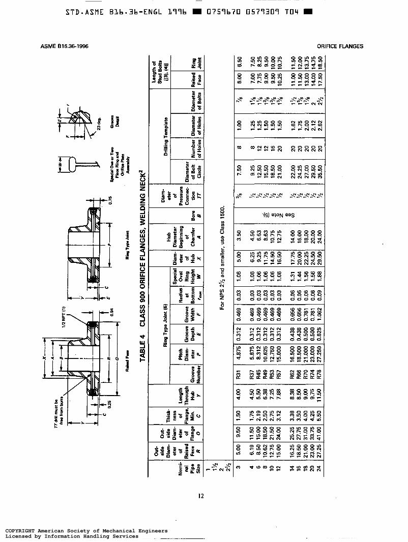
ERA
L N
OTE
: D
imen
sion
s ar
e in
inch
es.
NO
TES:
(1
) O
ther
NPT
siz
es m
ay b
e fu
rnis
hed
if re
quire
d.
(2)
All
othe
r di
men
sion
s ar
e in
acc
orda
nce
with
AS
ME
B16
.5.
(3)
In c
onfo
rman
ce w
ith A
SM
E B
16.5
, st
ud b
olt
leng
ths
do n
ot in
clud
e po
int
heig
hts.
(4
) B
olt l
engt
hs fo
r ra
ised
face
flan
ges
incl
ude
allo
wan
ce fo
r or
ifice
and
gas
ket t
hick
ness
of
0.25
in.
for
NPS
3-1
2 an
d 0.
38 i
n. fo
r
(5)
Bor
e is
to b
e sp
ecifi
ed b
y th
e pu
rcha
ser.
(6
) R
ing
join
t fla
nges
larg
er th
an N
PS 1
2 w
ill r
equi
re a
ngul
ar m
eter
taps
as
show
n in
Fig
. 3.
NPS
14-
24.
Bol
t len
gths
for
ring
type
join
t fla
nges
incl
ude
allo
wan
ce o
f 0.6
2 in
. for
NP
S 3
-10
and
0.75
in. f
or N
PS 1
2.
VI x
m
m
t-'
0-
W
0-
I m z
E; m
COPYRIGHT American Society of Mechanical EngineersLicensed by Information Handling ServicesCOPYRIGHT American Society of Mechanical EngineersLicensed by Information Handling Services
69946361BEMSASEGWFECMRO
_m_m_“_E___>>°___WWm33LQMQE5___mg2562___>>N_wmz___m~_(_“__g=w_MQGCN:E2UEEav_
__%_w_‘_2__a$55BEUBWUps2Eomav
_N_22he_____mgU5elm$2é_C_N06*08=_w>>o__m~m__g_g_Mgrégatact6*gm;tomgt:mmz
_2_C_“MdU5NT“mmz_2_____mN_o$0WMUCv_UEH_Hmggmug8_t__o_£UU___M>>°__mQ_g_u:_$m___w_*83U35__2m mcgtomE
_m_£m_Q£EaQ_u:_OC_6:onW£mCU_:8“S3_m_m_mm__2m<£3)ggshovegC_5
_m_m__mm__>_w< g8c%__8U_wEmago_2__QE__u55°__<E
__v2___U2t_u2_mE__aB:5WQN_MPmzagoE
“$62
_$_l_U________P52_°_m_EE_D"Ebz__<_u_mzm_o
31
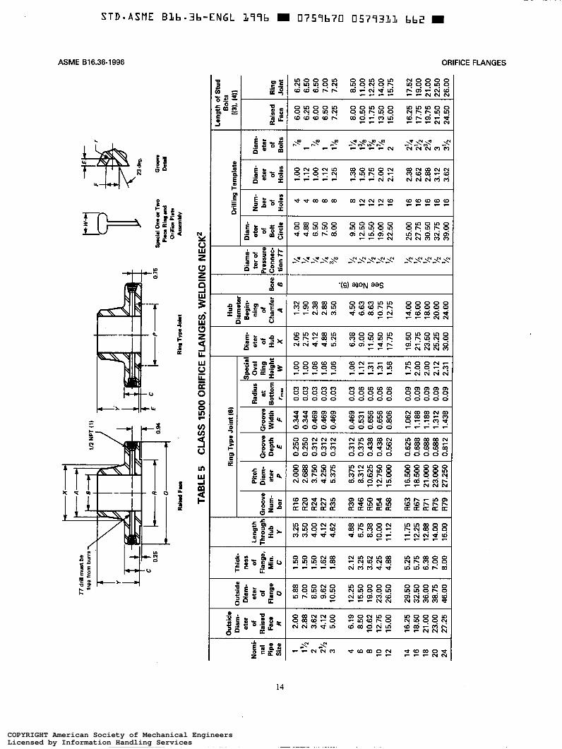
No
mi-
n
al
Pip
e S
ize
1 11/2
2 2'12
3 4 6 8 10
12
14
16
18
20
24
+
P
r
Tid
rill
mus
l be
free
from
bur
rs
Ou
tsid
e D
iam
- et
er
of
Rai
sed
Face
R
2.00
2.
88
3.62
5.00
6.19
8.
50
10.6
2 12
.75
15.0
0
16.2
5 18
.50
21.0
0 23
.00
27.2
5
4.12
Juts
ide
Dia
m-
eter
of
Fl
ange
0
5.88
7.
00
8.50
9.
62
10.5
0
12.2
5 15
.50
19.0
0 23
.00
26.5
0
29.5
0 32
.50
36.0
0 38
.75
46.0
0
Pw
Rin
g an
d O
iifim
Pla
ts
Thic
k-
ness
of
Fl
ange
, M
in.
C
1.50
1.
50
1.50
1.
62
1.88
2.12
3.
25
3.62
4.
25
4.88
5.25
5.
75
6.38
7.
00
8.00
Rai
md Fr
r R
ing
Ty
p J
oh
l A
ssem
bly
TAB
LE 5
C
LASS
150
0 O
RIF
ICE
FLA
NG
ES, W
ELD
ING
NE
CK
2
Sro
ove
Dep
th
E
0.25
0 0.
250
0.31
2 0.
312
0.31
2
0.31
2 0.
375
0.43
8 0.
438
0.56
2
0.62
5 0.
688
0.68
8 0.
688
0.81
2
Rin
g Ty
pe J
oin
t (6)
Gro
ove
Wid
th
F
0.34
4 0.
344
0.46
9 0.
469
0.46
9
0.46
9 0.
531
0.65
6 0.
656
0.80
6
1.06
2 1.
188
1.18
8 1.
312
1.43
8
3adi
us
at
lott
om
rm
a.
0.03
0.
03
0.03
0.
03
0.03
0.03
0.
06
0.06
0.
06
0.06
0.09
0.
09
0.09
0.
09
0.09
Pitc
h D
iam
- et
er
P
Spe
cia
Ova
l R
ing
Hei
gh
i W
1.00
1.
00
1.06
1.
06
1.06
1.06
1.
12
1.31
1.
31
1.56
1.75
2.
00
2.00
2.
12
2.31
2.00
0 2.
688
3.75
0 4.
250
5.37
5
6.37
5 8.
312
10.6
25
12.7
50
15.0
00
16.5
00
18.5
00
21.0
00
23.0
00
27.2
50
Nu
m-
ber
of
Hol
es
4 4 8 8 8 8 12
12
12
16
16
16
16
16
16
Dia
m-
eter
of
H
oles
1.00
1.
12
1.00
1.
12
1.25
1.38
1.
50
1.75
2.
00
2.12
2.38
2.
62
2.88
3.
12
3.62
Leng
th
ihro
ug
h
Hub
Y 3.25
3.
50
4.00
4.
12
4.62
4.88
6.
75
8.38
10
.00
11.1
2
11.7
5 12
.25
12.8
8 14
.00
16.0
0
I Hub
I G
roov
e N
um
- be
r
R16
R
20
R24
R
27
R35
R39
R
46
R50
R
54
R58
R63
R
67
R71
R
75
R79
Dia
met
er
4.12
Dia
m-
eter
of
B
olts
78
1 1 ?$
1'/8
lk4
13/8
178
178
2 2'14
23/4
2'1'
3 3'/2
Rai
sed
Rin
g Fa
ce
Join
t
6.00
6.
25
6.25
6.
50
6.50
7.
00
6.00
6.
50
7.25
7.
25
8.00
8.
50
10.5
0 11
.00
11.7
5 12
.25
13.5
0 14
.00
15.0
0 15
.75
16.2
5 17
.52
17.7
5 19
.00
21.5
0 22
.50
24.5
0 26
.00
19.7
5 21
.00
Ti
6.38
9.
00
14.5
0 11
.50
-
Dia
me-
te
r of
're
ssun
:o
nnec
. tio
n 7i -
1 14
Y4 '/4 '14 /a 92 '4
5;
12
'12 12
72 72 4 5;
3 1 1 1
rn -
4.50
E
6.63
8.
63
p>
10.7
5 2
Dia
m-
eter
of
B
olt
Cir
cle
17.7
5
19.5
0 21
.75
23.5
0 25
.25
30.0
0
4.00
4.
88
6.50
7.
50
8.00
9.50
12
.50
15.5
0 19
.00
22.5
0
25.0
0 27
.75
30.5
0 32
.75
39.0
0
12.7
5
14.0
0 16
.00
18.0
0 20
.00
24.0
0
Len
gth
of S
tud
I Bo
b
Dri
llin
g T
emp
late
i(3
L (4
1
VI
z
m
W
I+ r
w
n-
I m
z
GI
I- I.' n
n
r
0
4
vi
d
r
4 0
0
vi
4
d
w
I+ I+ n-
n-
m
COPYRIGHT American Society of Mechanical EngineersLicensed by Information Handling ServicesCOPYRIGHT American Society of Mechanical EngineersLicensed by Information Handling Services
SEGNMFEmWRO69946361BEMSA
CQQNQMNNOQPN8_@__NQ:£9OQ_q_mN_N_2:__hidgsODSOmdOmdmN_@
OQVN3R@N_2@N_:_gm:QQE9w___H_@N_____32CO6as$62;__N_m86
M§~\_~v\_N
NQ\N__m\m_m\n_m\___
PN
__N
x"NFMadNQNadNPMHadM”:OM‘WM;mg2;°°___N____2:
288N\_2gsN\_M:3%N\_2gsN\_28%N\_9SmN\_282N\_2g__|=N\_2ggN\_MO:N\_QSHm85_\_Q8?_\_QQ3_\_ MW8dw\m
__\_
S33NO18Q
OQQNOO_ONDQ_Q__QO_@__QQSm§N__gsM66$6OQQHEMMugndQQF§_u___
OQOMgOQMNQ____N%_d__gtOw:Oq:OQQ“W2mgMQQNS‘mmQVN
ENN___NCONCON£|___Q35;__m___éQ3aswe9':O3o°___
Q06M86gd868686©qOQQO86MQOMQQM668686M06
mm:N5___8:mm:N2:
NEdQQQQQWQOgg@N®_O
OMNSNQOQMNOOO___NOOQ282:
QtMEXKIREmg
OqgOq:8_m:_g:
CO684%86R6mug
COM;gQOdM“3%82
266MEQD©@©dEQQQgd
$2Q36Q92“____NM_ON36
OOQEOQNFmN@_O_g dand
QUESIREQVIQWI
N__:OQ2W3_kd8*
8*Q“?NO“mug@_N
gOQMNOqg“EMF@N_N_
asQQYOQ$_O$2Q_g_O
N:3N56N56gadHEQO
mhqmOm“?___m:"WQQNOOON
mgNI__‘NIONEOE
N3N3“OQQ86W3
8‘No;Q28;°m__
QQ2NQQHid9:MM“
DNNN_&QQMNONQqa2H522magS89NP_H_N__2NQ2Qand@26¢86MN;N\_NN:Nad
N\__
8_N_
____°_’2E
8:‘:_:_
£0”_Oat
:_O___*0=3_________
02°:20:0t=0:*0=0“-OOCCOQ2°”__o*F_ ___°anSO____gO____
*°
_E__z333__8“EC
=3__n__£0”
____ S__5__3
*_______*0as
E
:5‘
“________:____8___m__“__§EaS£006_N>°“Siam
£55_25_°____m£‘Egg____g__wmg:
U‘WQ__g>OO
gnas_______z________E:ODCIE:86____“_°U>O°__°__u_____________g§_“_3
:35£233=3
__5E
‘a sgn'8°_____'
____w________h_w______5_______E“_______atDE:
o___a__°____g
$58tgmM3:g__“___:_._“__I___
3'____°258°
kK
=85
NZQNZw_’__n___m__s_m_oZ5"_m_U_"___“_oA52WWSQMWJ <___
>1E031Ea‘ac_EE8.:sis“E.____Eit
i
‘S
it3-‘
\I\\l“i\
‘A
Mi‘_V>
M _A“_
éu____________!°_._MloTllmUW 3°_E_;~“V____i_\_‘_\_m‘I5
__|%‘_‘_x\
Lt'_
A::2N:m8:55°:3:
3$2:______t
QX
GENE
RAL
NO
TE: D
imen
sion
s ar
e in
inch
es.
NO
TES
: (1
) O
ther
NPT
siz
es m
ay b
e fu
rnis
hed
if re
quire
d.
(2)
All
othe
r di
men
sion
s ar
e in
acc
orda
nce
with
AS
ME
B16
.5.
(3) I
n co
nfor
man
ce w
ith A
SME
B16
.5,
stud
bol
t len
gths
do
not i
nclu
de p
oint
hei
ghts
. (4
) B
olt l
engt
hs fo
r ra
ised
face
flan
ges
incl
ude
allo
wan
ce fo
r or
ifice
and
gas
ket t
hick
ness
of 0
.25
in. f
or N
PS
1-1
2 an
d 0.
38 in
. for
(5)
Bor
e is
to b
e sp
ecifi
ed b
y th
e pu
rcha
ser.
(6)
Rin
g jo
int
flang
es la
rger
than
NPS 6
will
req
uire
ang
ular
met
er ta
ps s
how
n in
Fig
. 3.
NP
S 1
4-24
. B
olt
leng
ths
for
ring
type
join
t fla
nges
incl
ude
allo
wan
ce o
f 0.
62 in
. fo
r N
PS
1-6
.
w
r
I m
z
COPYRIGHT American Society of Mechanical EngineersLicensed by Information Handling ServicesCOPYRIGHT American Society of Mechanical EngineersLicensed by Information Handling Services
69946361B_____WASEGMFEmWRO
_m_m_“_EESOLWasEEE___N_DmC@Q______g____;Qmlz55$95@095:E_O__GEEQ
__$22___a2:5UUEUUQWBOH290mQ
_w’_mlzL8_E3°B_8Cm_>>O___mg3_U____Wwm gE2atgt5W:a5_g__‘N|3mlz
__2_C_wmdE5NF;mmz6*_C_mN_o*0$2v_U_£“gigEa8E6__2QuCN>>O__Ng___U____WWm___N_*asE28_£m£mg_H_Om5
dzggHEOQ%J_OC_HOEOwWEm5_:3new_m_w_mm__>_w<£_>>QOCUF___O__COQE5
_m_®_mw_>_m<___H__>>8__5E8gEpaW___O_WC®E_u550__<E
_g____Jg\_=8__mm_l__aB>558%_Ez$56E
“B02
_$___U____EpaQOEHOEE“E102A<r_m_2mo
5I
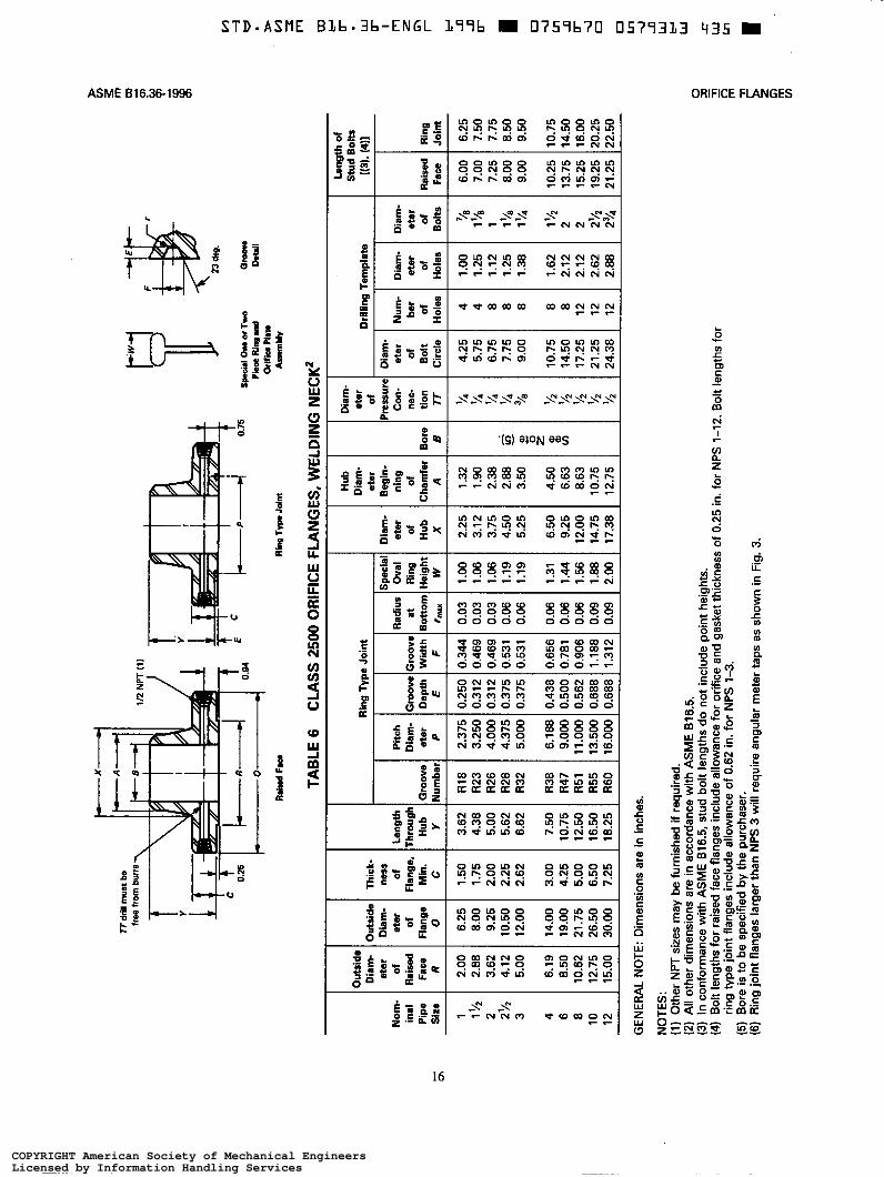
Spe
cial
b
diu
s O
val
at
Rin
g Lo
ttom
Hei
ght
rmax
w
0.03
1.00
0.03
1.06
0.03
1.06
0.06
1.19
0.06
1.19
0.06
1.31
0.06
1.44
0.06
1.56
0.09
1.88
0.09
2.00
Dia
m-
eter
of
H
ub
x 2.25
3.12
3.75
4.50
5.25
6.50
9.25
12.00
14.75
17.38
Ot
ress
ure
Con
- ne
c-
tio
n
77
94
/4 5% 51,
/s '/2 '/z '/2 '/2 '/2
1 3
Dia
m-
eter
of
B
olt
C
ircl
e
4.25
5.75
6.75
7.75
9.00
10.75
14.50
17.25
21.25
24.38
Dia
m-
eter
of
B
olts
'/s
ll/s
1 l1/S
1'/4 11/2
2 2 2l/2
274
.. .
Rai
sed
Face
6.00
7.00
7.25
8.00
9.00
10.25
13.75
15.25
19.25
21.25
Num
- be
r of
Holes
4 4 8 8 8 8 8 12
12
12 -
.
Dia
m-
eter
of
H
oles
1.00
1.25
1.12
1.25
1.38
1.62
2.12
2.12
2.62
2.88
TTdr
ill m
u% b
e fr
ee fr
om b
uns
rwl D
Sp
c*l
On a T
wo
r
23 d
eg.
0-
VI 3
m
Rin
g T
yp
. Join
t
TAB
LE 6
C
LAS
S 2
500
OR
IFIC
E FL
AN
GES
, WE
LDIN
G N
ECK
' a3
I+ D-
W
0-
I m
-
Bor
e B
-
)uts
ide
Dia
m-
eter
of
R
aise
d Fa
ce
R
-
)uts
ide
Dia
m-
eter
of
Fl
ange
0
-
Leng
th
'hm
ugh
Hub
Y
-
No
m-
inal
P
ipe
c
Siz
e m
1 2 3 4 6 8 10
12 1 '/2
2Y2
Dia
m-
I Le
ngth
of
I Stu
d H
ub
Dia
m-
eter
B
egin
- ni
ng
of
:har
der
A
Ob
011 -
Rin
g Jo
int
6.25
7.50
7.75
8.50
9.50
10.75
14.50
16.00
20.25
22.50
-
-
Rin
g Ty
pe J
oint
D
rilli
ng
Tem
pla
te
I N
3).
eter
I
Thic
k-
ness
of
Fl
ange
, M
in.
C
-
Sroo
ve
Dep
th
E
Pec
h D
iam
- et
er
P
üroo
vr
Wid
th
F Sr
oove
lu
mbe
i
2.00
2.88
3.62
4.12
5.00
6.19
8.50
10.62
12.75
15.00 -
6.25
8.00
9.25
10.50
12.00
14.00
19.00
21.75
26.50
30.00
1.50
1.75
2.00
2.25
2.62
3.00
4.25
5.00
6.50
7.25
3.62
4.38
5.00
5.62
6.62
7.50
10.75
12.50
16.50
18.25
R18
R23
R26
R28
R32
R38
R47
R51
R55
R60
2.375
3.250
4.000
4.375
5.000
6.188
9.000
11 .oo
o 13.500
16.000
0.250
0.312
0.312
0.375
0.375
0.438
0.500
0.562
0.688
0.688
0.344
0.469
0.469
0.531
0.531
0.656
0.781
0.906
1.188
1.312
1.32
1.90
2.38
3.50
4.50
6.63
8.63
10.75
12.75
2.88
GEN
ERA
L N
OTE
: D
imen
sion
s ar
e in
inch
es.
NO
TES
: (1
) O
ther
NPT
siz
es m
ay b
e fu
rnis
hed
if re
quire
d.
(2) A
ll ot
her
dim
ensi
ons
are
in a
ccor
danc
e w
ith A
SM
E 816.5.
(3) I
n co
nfor
man
ce w
ith A
SM
E B16.5,
stud
bol
t len
gths
do
not i
nclu
de p
oint
hei
ghts
. (4) B
olt l
engt
hs fo
r ra
ised
face
flan
ges
incl
ude
allo
wan
ce fo
r or
ifice
and
gas
ket t
hick
ness
of 0.25 i
n. fo
r N
PS 1-12. B
olt l
engt
hs fo
r
(5) B
ore
is to b
e sp
ecifi
ed by
the
purc
hase
r. (6) R
ing
join
t fla
nges
larg
er th
an N
PS 3 w
ill r
equi
re a
ngul
ar m
eter
taps
as
show
n in
Fig
. 3.
ring
type
join
t fla
nges
incl
ude
allo
wan
ce o
f 0.62 in
. for
NPS
13.
J=
W
z A Ln
n 6" z
I
c4Y
COPYRIGHT American Society of Mechanical EngineersLicensed by Information Handling ServicesCOPYRIGHT American Society of Mechanical EngineersLicensed by Information Handling Services
SEGWFEmWRO%91"W3&1BEMSA
_mat_______>>OMGMagassa___m___wp___a2E;MwlzCs:__¢m___N_mgsz_EO_DEEav_
ag__"____a2:3BEOQQMB92PamE
“IFwmzhe_C_Nwd*9QUCN>>O__@%____“____895:“E2Quagt
heM£m___O_H_Om_N_|_22kg____mg*0QQEEE“gagg8550heOUCN>>O__N%___U___$2288_Va_g_heM£m5_H_OmAs
_§%__HEOQ%____g_gO”EBCBH_Ongs_m_Q_mm_S_m<___=>>8____wE_2__OO____5
damw_)_w< gQUCNEOUUNE9520§_m_E__vE50__<E
_g_____g__tg___2Ee3>9:MON“___n_ZB50E
“$52
_w9_OC_EENWCO_W_aE_QE02émmzww
HENNgOO_@__O@_S_$52‘36Q3AK‘OMS$Nd
8:g$2$22__mN_EHadHadHHS8NCO6
§N\_NNNN\__Q;Q;_'
w\__Q“
_:__N_@ _O__mug$6Had
8“NF83N\_N2NFanN\_N;NFatN\_adQ3:N\_%$__N£9N\_3
WQg
adad3;NM__
Q2Q86QMmgQMm:'\_MN:N£6_\_mgQmg__\_8__QEN‘?_“\_
QQ:__K_:_OONFmad86MgA56EaNF“@N_N
oz8;mg3;2:2;2___2:2:°°___
@qOQQQ86gd8686868686MQD
§h___$2;Q86EEOQMQO
QQQO£66$2828;
__Mm_OFMQOQ92“$_‘_OS86
_EU_O£2N56N5682
OQQSOQ__m_M__OOQ____CD06M630Q86__gQ<OOQQ82£2
OME_§_SCNQKQMINMCWNIQNIWNIWE
gQQ2Oqm‘_\'_O_qmNW6N3COM“QQVNQM
as86OQW@N_QgmNQN@N_NCONmm:OD___
OQOM88Ak_ROqgDq:Dqg82mgQ3@Nd
__q£QPNPNQ236edCO6N5‘$6QQN8“
NFOF_QQVMQRNN\___‘
v___°____=_____
8:‘wag
8_°D3‘O33:‘EEO‘EggIE5:as
tN<8:2°”__:____2_Q'02*0ecum______
3:‘:3:°_°___°
=0”
‘O:2*0
_§_E_£8E5_°£25
:3.E§mc_§_°______
XA5:3=3
E_______
:5‘
“_____£_____§m_
u.
_I>°n_____8_
_EQ_n_D_____nMU_£EEO“_EIEEugwO8:
K“_________;_____8D)OO__°26059
13‘_§_n___SE
__2_E__z*20056______
__?O________g__I_“___a__3
Q____:3
82__EO___’_____mEEas“____O__'a>___“E:_:_____'
Og_:_“_
__°is_______°’___8__°
t0°C“_§_-_u_
S=3“_______ _Q2550
=5at_I____£52
___§~__‘_§
k_.\&
KA
_K_‘__WT§_
NMUNZo_’__q_m__s_m_w_,_<l_"_MOEEOQBNWMSUQm___2_F
552“=5EF'51in‘.1:‘EL£26
_!R_3.PE‘ t
5!
Um+llU
F1
_mgTli_‘I Qxi
si}
_R_>wiy
=__K2N:
Q1X
>
E3:53.2‘3:2:______h
AS ME B 16.36- 1 996
ANNEX A QUALITY SYSTEM PROGRAM
(This Annex is not part of ASME 616.36-1996 and is included for information only.)
The products manufactured in accordance with this Standard shall be produced under a quality system program following the principles of an appropriate standard from the IS0 9000 series.’ A determination of the need for registration andor certification of the
’ The series is also available from the American National Standards Institute (ANSI) and the American Society for Quality Control (ASQC) as American National Standards that are identified by a prefix “ Q replacing the prefix “ISO. Each standard of the series is listed under Annex B.
product manufacturer’s quality system program by an independent organization shall be the responsibility of the manufacturer. The detailed documentation demon- strating program compliance shall be available to the puchaser at the manufacturer’s facility. A written sum- mary description of the program utilized by the product manufacturer shall be available to the purchaser upon request. The product manufacturer is defined as the entity whose name or trademark appears on the product in accordance with the marking or identification require- ments of this Standard.
17
COPYRIGHT American Society of Mechanical EngineersLicensed by Information Handling ServicesCOPYRIGHT American Society of Mechanical EngineersLicensed by Information Handling Services
STD-ASHE B1il=-Ell:-ENGL ]i“l‘l|= K [l75“ll=?El E|5?'=lEl1|Ll El71| —
ASME B16.36-1996
ANNEX A
QUALITY SYSTEM PROGRAM
(This Annex is not part of ASME B16.36-1996 and is included for information only.)
The products manufactured in accordance with thisStandard shall be produced under a quality systemprogram following the principles of an appropriatestandard from the ISO 9000 series.‘ A determinationof the need for registration and/or certi cation of the
1 The series is also available from the American National StandardsInstitute (ANSI) and the American Society for Quality Control(ASQC) as American National Standards that are identi ed by apre x "Q" replacing the pre x “ISO”. Each standard of the seriesis listed under Annex B.
product manufacturer’s quality system program by anindependent organization shall be the responsibility ofthe manufacturer. The detailed documentation demon-strating program compliance shall be available to thepuchaser at the manufacturer’s facility. A written sum-mary description of the program utilized by the productmanufacturer shall be available to the purchaser uponrequest. The product manufacturer is de ned as theentity whose name or trademark appears on the productin accordance with the marking or identi cation require-ments of this Standard.
~
STD-ASME BLb.3b-ENGL 377b m 0757b70 0577335 208 m
ORIFICE FLANGES ASME 816.36-1996
ANNEX B
REFERENCES
(This Annex is an integral part of ASME 816.36-1996 and is placed after the main text for convenience.)
The following is a list of standards and specifications referenced in this Standard showing the year of approval.
ASME Publications (Approved as American National Standards)
ASME B1.20.1-1983 (R1992) ASME B16.5-1996 ASME B16.11-1991
Pipe Threads, General Purpose (Inch) Pipe Flanges and Flanged Fittings Forged Fittings, Socket-Welding and Threaded
ASME Boiler and Pressure Vessel Code, 1995 Edition (Including Addenda through 1995)
Section 1 Power Boilers Section I1 Materials Section I11 Section VIII, Division 1 & 2
Nuclear Power Plant Components Pressure Vessels
International Standards Organization (ISO)
IS0 9000-1: 1994
IS0 9000-2: 1993
Quality management and quality assurance standards - Part 1: Guidelines for selection and use Quality management and quality assurance standard - Part 2: Generic guidelines for the application of IS0 9001, IS0 9002, and IS0 9003 Quality management and quality assurance standards - Part 3: Guidelines for the application of IS0 9001 to the devel- opment, supply and maintenance of software Quality systems - Model for quality assurance in design, de- velopment, production, istallation, and servicing Quality systems - Model for quality assurance in produc- tion and servicing Quality systems - Model for quality assurance in final in- spection and test
IS0 9000-3: 1991
IS0 9001: 1994
IS0 9002: 1994
IS0 9003: 1994
COPYRIGHT American Society of Mechanical EngineersLicensed by Information Handling ServicesCOPYRIGHT American Society of Mechanical EngineersLicensed by Information Handling Services
STD-ASME BLl=.Elb-ENGL i=1=u= — |]?5“lb?E| u5?=131.s ans —
ORIFICE FLANGES ASME B16.36-1996
ANNEX BREFERENCES
(This Annex is an integral part of ASME B16.36-1996 and is placed after the main text for convenience.)
The following is a list of standards and speci cations referenced in this Standard showingthe year of approval.
ASME Publications (Approved as American National Standards)ASME Bl.20.l-1983 (R1992) Pipe Threads, General Purpose (Inch)ASME Bl6.5-1996 Pipe Flanges and Flanged FittingsASME B16.l1-1991 Forged Fittings, Socket-Welding and Threaded
ASME Boiler and Pressure Vessel Code, 1995 Edition (Including Addendathrough 1995)Section 1 Power BoilersSection II MaterialsSection III Nuclear Power Plant ComponentsSection VIII, Division 1 & 2 Pressure Vessels
International Standards Organization (ISO)ISO 9000-1: 1994 Quality management and quality assurance standards - Part
1: Guidelines for selection and useISO 9000-2: 1993 Quality management and quality assurance standard - Part
A 2: Generic guidelines for the application of ISO 9001, ISO9002, and ISO 9003
ISO 9000-3: 1991 Quality management and quality assurance standards - Part3: Guidelines for the application of ISO 9001 to the devel-opment, supply and maintenance of software
ISO 9001: 1994 Quality systems - Model for quality assurance in design, de-velopment, production, istallation, and sen/icing
ISO 9002: 1994 Quality systems - Model for quality assurance in produc-tion and servicing
ISO 9003: 1994 Quality systems - Model for quality assurance in nal in-spection and test
19
~~ ~
STD-ASME B L b - 3 b - E N G L L99b 0759b70 05793Lb 144
ASME B16.36- 1996 ORIFICE FLANGES
ASQC
IS0
Publications of the following organizations appear in the above list:
ASME The American Society of Mechanical Engineers 345 East 47th Street, New York, NY 10017-2392
ASME Order Department 22 Law Drive, Box 2300, Fairfield, NJ 07007-2300
American Society for Quality Control P.O. Box 3005, Milwaukee, WI 53201-3005
International Organization for Standardization 1, rue de Varembe, Case postale 56, CH - 1121 Genthe 20, SwitzerlandSuisse
IS0 documents are also available from ANSI. Publications appearing above which have been approved as American National Standards may also be obtained from ANSI.
ANSI American National Standards Institute, Inc. 11 West 42nd St., New York, NY 10036
20
COPYRIGHT American Society of Mechanical EngineersLicensed by Information Handling ServicesCOPYRIGHT American Society of Mechanical EngineersLicensed by Information Handling Services
STD.ASl‘1E B].l=-3b-ENGL 1.=|=u= I nvsasvu lJ5?=lElLl= inn I
ASME B16.36-1996 ORIFICE FLANGES
Publications of the following organizations appear in the above list:
ASME The American Society of Mechanical Engineers345 East 47th Street, New York, NY 10017-2392
ASME Order Department22 Law Drive, Box 2300, Fair eld, NJ 07007-2300
ASQC American Society for Quality ControlP.O. Box 3005, Milwaukee, WI 53201-3005
ISO International Organization for Standardization1, rue de Varembé, Case postale 56, CH - 1121 Genéve 20,Switzerland/Suisse
ISO documents are also available from ANSI. Publications appearing above which havebeen approved as American National Standards may also be obtained from ANSI.
ANSI American National Standards Institute, Inc.11 West 42nd St., New York, NY 10036
20