Embed Size (px)
Citation preview

1
ASL T6 / T7 / T8 / T9 FLOOR GRINDING MACHINES
MANUAL

2
Contents
Preface 3
1.1 Safety Guide 4 1.2 Precautions 4 Chapter II 5
Purchase Check, Technical Parameter and Product Description 5
2.1 Purchase Check 5 2.2 Nameplate and Model Description 5 2.3 Technical Parameter Description 6 2.3.3 7 2.3.4 7 Chapter III 7
Operation Instruction 7
3.1 Equipment Operation Method 7 3.2 Equipment Storage after Use 9 3.3 Instructions for using Floor Grinding Machine 9 3.4 Equipment Dismounting Steps and Precaution 10 Chapter IV 10
Equipment Wiring and Inverter Reset 10
Wiring the equipment, please be sure to operate strictly as per the following instruction, so as to prevent
unnecessary loss 10
4.1 Notices for Wiring 10 4.2 The general wiring diagram of switch box, inverter and motor 11 4.4 Real object of motor wiring box & indicating lights 11 4.5 Inverter Reset 12 Chapter V 12
Equipment Maintenance and Overhauling 12
Machine Diagram 13 / 14 / 15 / 16 5.1 Maintenance and Overhauling 17 Chapter VI 17
Quality Assurance 17
6.1 Warranty Scope and Period 18
6.2 Warranty Condition 18

3
Preface
Thank you for purchasing the ASL-T6 / T7 / T8 / T9 floor grinding machine.
This ASL-T6 / T7 / T8 / T9 floor grinding machine is the newest generation of equipment independently developed by ASL. This machine is multi-function integrating grinding, renovating, polishing, and cleaning into one. The machine greatly improves surface preparation and maintenance efficiency of concrete, stone and epoxy floor so as to meet the high-standard requirements of floor surface treatment and maintenance as well as saving the contractor time and money.
This manual is a detailed description for the application, maintenance, precaution, fault diagnosis and countermeasures of the ASL-T6 / T7 / T8 / T9 machine. This is the instructive document used to ensure the machines excellent performance and safe operation, please read it carefully and keep it in a readily available place.
If there are any problems or special requirements in application, please contact us.
Our company always commits to the constant innovation and improvement of the equipment. If there are any changes for the relevant information of this equipment of this type, we will update it as soon as possible.
Chapter I Safety and Precautions
For your safety, and the protection of the equipment, before using this machine, please make sure to read this manual carefully,
and strictly follow it for the process of transporting, commissioning, operating and troubleshooting.

4
1.1 Safety Guide
[1]: The operator must wear water-proof and insulating work shoes and gloves, and barefooted operation is prohibited to prevent personal casualty from electric shock. [2]: The external connecting wire must be more than 4m2 and must be grounded to prevent electric shock. [3]: Before using the equipment, you must check whether the power wire is damaged or aging. If so, immediately replace the power wire to prevent the equipment from short circuit and electric leakage. [4]: The operator on the machine is prohibited from preventing equipment shut-down for over-load or personal casualty for electric leakage. Don’t put the equipment, the power and the socket into water or over-humid environment for preventing the equipment damage from the short circuit. [5]: When conducting wet grinding, waterproof protection should be conducted for the water tank, inverter and control panel for preventing the equipment non-operation or personal casualty from equipment short circuit or electric leakage. [6]: When using the equipment, don’t roll on the electric wire to prevent potential safety risk from electric wire damage. [7]: When using the equipment, don’t insert the plug with wet hands for preventing injuries and deaths from electric shock.
1.2 Precautions
[1]: After dry grinding and wet grinding treatment, completely clean the bottom part of the equipment to increase the
service life.
[2]: When conducting dry grinding with the equipment, please connect the vacuum cleaner, to ensure there is dust-free
operation, decrease the inverter load and guarantee the equipment is running normal.
[3]: In the process of replacing tooling and transporting, please be sure to put down the equipment gently for preventing
the strike and oil leakage of the gear box from the improper operation (If one person can’t carry the equipment easily in
the operation process, please look for other people to assist).
[4]: In a certain range of output frequency, the frequency inverter may produce the resonance which will cause the
equipment to stop working, under such a circumstance, please avoid the resonant frequency operation.
[5]: When conducting operation on the floor with a large difference of level, please be sure to grind from the higher to the
lower to prevent damage to the grinding plate and gear box from oversize difference of floor level.
[6]: Regularly check the grinding plate, if you find any loose screws on the grinding plate, tighten and maintain.
Chapter II
Purchase Check, Technical Parameter and Product

5
Description
2.1 Purchase Check
[1]: Please check whether the product package is damaged for improper transportation before opening the
case.
[2]: Check whether the specification and the model of the product conform to those of the purchased
machine.
[3]: All ASL-T2 floor grinding machines have passed strict quality inspections. Please check for certificate of quality, product
user manual and warranty card.
[4]: Check whether there are any damages inside of the machine. If there is obvious damages, please don’t operate and
use the machine, and timely contact our company or the dealer to avoid accidents.
[5]: Check whether the items are complete, including the machine and standard fittings (the standard fittings are as
follows).
2.2 Nameplate and Model Description

6
2.3 Product Description
2.3.1 Product Structure Description

7
2.3.2 Main Product Feature
[1]: U-handle, which can rotate around 360°, and is safe and reliable with convenient operation conforming to operator
ergonomics.
[2]: Special big multi-functional magnet chassis, which enables the grinding material installation and replacement to be
more convenient and quicker, and high-speed running to be safer.
[3]: The central integrated design of the control panel, which can choose the speed and improve the equipment stability
as well as achieve a low-noise working environment.
[4]: The built-in vacuum cleaner connection device, which can achieve a dust-free working environment,
thus good for staff’s health and equipment’s maintenance.
[5]: Easy operation, which enables the operator to easily complete the whole construction process by strictly following the
manual.
2.3.4 Product Design Concept
In order to satisfy the high-quality floor pursuit of concrete and stone industry in recent years, ASL Machines USA has
independently developed a professional dry and wet amphibious floor grinding machine integrating multi-functions for
grinding, polishing and refurbishing into one so as to meet the grinding, polishing and refurbishing requirements of various
kinds of floors.
Chapter III
Operation Instruction
3.1 Equipment Operation Method

8
3.1.1 Equipment Operation Preparation
[1]: Prior to starting, check whether the power switch is in the off state to ensure the safety.
[2]: First adjust the handle in the line-style, and then hold the handle and with one foot stepping on the step bar and press
downwardly; after the equipment is fixed on the ground, check whether the external parts are complete, whether there is
any wrong installation of tools, neglected installation and loose parts. Immediately solve the problem if finding these issues.
[3]: After checking, press the equipment down until the chassis touch the ground, and lay it flat.
[4]: Apply grinding tooling onto the equipment, and the basic steps on the following page:
(1) As shown in Figure 2-1, the equipment chassis is loaded with a polishing plate
(2) Place desired tooling on machine utilizing the magnetic plates.
(3) After loading, check whether the parts are complete once again.
(4) Install or tighten the handle, clockwise rotate the black rotary handle to the tightest state. Rotate in the reverse
direction when dismounting the handle as shown in Figure 3.
(5): Pull the handle of the swing arm, adjust the handle to the height suitable using the chuck
3.1.2 Mechanical Operation
[1]: Check to ensure the voltage parameters are normal, and then connect both ends of the power wire into the
corresponding plug as shown in Figure 5. As shown in Figure 6, if the red indicating light is on, everything is okay. When
beginning to operate, ensure the green indicating light is on.
[2]: The co-rotation and inversion switch controls the grinding direction, if the switch is on the forward setting, the machine
will grind clockwise; if it is on the inversion, it grinds reversely. The real object of co-rotation and inversion switch is as
shown in Figure 7.
[3]: The chassis rotation direction is as shown in Figure 8 and 9.
[4]: The rotation speed controller can regulate the grinding speed, clockwise rotation means speed up, counter clockwise
rotation means it slows down. The real object of rotation speed controller is as shown in Figure 10.
[5]: When conducting wet grinding, infuse proper amount of water into the water tank and regulate the water switch. When
the water switch rotates clockwise, it begins infusing water, to stop infusing water, rotate counter-clockwise. The real
object of water switch are as shown in Figure 11.
[6]: When dry grinding, the machine can connect with a vacuum cleaner to ensure dust-free operation.
The connector of vacuum cleaner is as shown in Figure 12, and the equipment connecting with the
vacuum cleaner are as shown in Figure 13, 14, 15 and 16.
Figure 13 shows the vacuum cleaner socket on the equipment.

9
Figure 14 is a picture about sweep-up pipe connecting.
Figure 15 is an overall connecting diagram of the equipment and the vacuum cleaner.
[7]: When everything is ready, turn on the power switch and regulate it to an appropriate rotation speed to
grind in a “double-cross” shape.
3.2 Equipment Storage after Use
[1]: Place the handle into the vertical position, disconnect and place the power wire in dry place.
[2]: Dismount the small grinding head from the machine, clean and dry them.
[3]: Use a half-dry clean rag to clean the machine. Pay attention to cleaning the machine surface after being used in wet
environment.
[4]: Use dry rag to clean the dust on air vent of the inverter and the motor to prevent fault from dust blocking in the next
application.
[5]: Check whether the machine and the accessories are in good condition, and make necessary repair and maintenance
before storage.
[6]: Keep the machine in the clean and dry place, and when storing, place the handset in the vertical position and fasten
tightly.
3.3 Instructions for using Floor Grinding Machine
[1]: In flattening the base plane, mount the diamond tooling on the machine and grind.
[2]: ensure to clean ground dust.
3.4 Equipment Dismounting Steps and Precaution
3.4.1 Carrying Steps
[1]: First, ensure machine is disconnected from power [2]: Ensure vacuum cleaner is disconnected.
[3]: Insert and lock the lifting bar into the socket.
[4]: One person lifts the lifting bar at ①, and one person lifts the handle at ②. Two
people together lift the machine at the same time.

10
3.4.2 Notes for Carrying [1]: Before carrying the machine, make sure the power switch is in off state, and there is no redundant water in the water tank. [2]: When carrying, please act lightly and carefully so as to avoid collision with small parts and the wall; if one person can’t complete this operation independently, please deploy other persons to assist. [3]: When break-down shipping, be sure to store all dismounted parts or screws to prevent loss. [4]: After using the lifting rob, return it to the original place for next use.
Chapter IV
Equipment Wiring and Inverter Reset
Wiring the equipment, please be sure to operate strictly as per the following instruction, so as to prevent unnecessary loss.
4.1 Notices for Wiring
[1]: If necessary self-wiring, wiring must be operated under the instruction of professional electricians or the technicians of the manufacturer. [2]: The electrical system of this equipment must strictly follow the parameters (voltage and frequency) designated on the nameplate, and before being connected with the input power, please check to ensure the voltage and the frequency of the external power supply are coincident. [3]: This equipment must be connected to the power system equipped with grounded electrically to prevent electric shock of the operator.
Note: The power wire (380V) of this equipment is equipped with 3 main traverse wire, 1 ground wire and 1 null wire. Connect the plug into appropriate power socket. The green-and-yellow core wire in the power wire is the ground wire, and don’t connect the ground wire to non-power socket.
4.2 The general wiring diagram of switch box, inverter and
motor
Figure 18
4.3 Real object of switch box & inverter

11
For switch box wiring details, please refer to Part A in Figure 18. For inverter wiring detail, please refer to Part
B and C in Figure 18.
4.4 Object of motor wiring box & indicating lights
For motor wiring detail, please refer to Part B in Figure 18. The indicating lights wiring details are as shown in
Part D of Figure 18.
4.5 Inverter Reset
When the equipment is shut down because of over-low voltage or overload, please turn off the power supply. Turn on the
power supply again after three minutes, and the equipment will recover to normal. If not, use the control panel to reset (reset
setting is as shown in Figure 19). The control panel of inverter is as shown in Figure 20.
Figure19

12
Figure 20
Equipment Diagram

13
T6
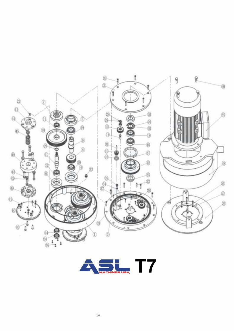
T7
14

15
T8
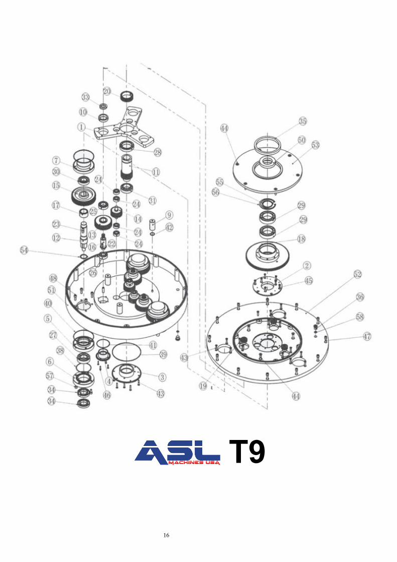
T9
16

17
Chapter V
Equipment Maintenance and Overhauling
5.1 Maintenance and Overhauling
[1]: Ensure the operator checks the grinding plate before using, if any loose bolts are located on the grinding plate or the
bolt, timely fasten the bolt and the nut for preventing uneven abrasion.
[2]: Using this equipment to grind, the operator shall ensure the surface is flat end even.
[3]: When using this machine, you must not block the vent hole. Ensure to clean the vent hole to ensure the normal
ventilation of the motor.
[4]: After 20 days in using, please clean the dust in the inverter and the vent hole, this operation can be done after trouble
shooting.
[5]: When dry grinding with this equipment, it must be equipped with a vacuum cleaner.
[6]: Please replace the gear oil (150#) regularly. The new machine needs to replace the gear oil after grinding
for about 1000m2, and once every 5 months after the run-in period.
[7]: Clean the external housing of this equipment after every use in the premise of outage, and put it
in dry and cool place for next use, thus extending the service life.
[8]: Please operate this equipment strictly following the instructions, so as to avoid unnecessary loss.

18
Machine Warranty Information
The quality of this product is warranted to be free from defects in both materials and workmanship. The machine warranty is as follows.
Part
Engine 2 Year Warranty Fuel System 2 Year Warranty
LP Tank (On select models) 1 Year Warranty Machine Body Parts 2 Year Warranty
Battery 1 Year Warranty
Note: this warranty does not cover certain wearable parts such as belts and engine tune up parts.
LP Engines are warranted by the engine manufacturer for the term specified by the engine manufacturer.
ASL Machines USA promises, at their discretion, to repair or replace any product or part(s) which
examination proves to be defective in either workmanship or materials used. ASL Machines USA must be notified directly within the warranty period.
This warranty does not cover damage, or failure caused by abuse, misuse, neglect, disassembly,
alteration, unauthorized modification, lack of proper maintenance, theft, or any damage by freight carriers. This warranty applies to parts and labor only, and does not cover any incidental or
consequential damages.
This warranty is non-transferable. ASL Machines USA
Chapter VII Fault Diagnosis

19
7.1 If the machine stops working suddenly during the operation, please follow the below instruction. [1]: Check to ensure the main power switch on the control panel is in the on position and is not damaged in any way. [2]: Check the internal wiring of the power socket of the machine to ensure it is not loose and the wire has a good connection. [3]: Check the motor wire connection box to ensure it is not moist and whether there are burned wires. [4]: To ensure there is sufficient current to operate this machine, we suggest customers to use 3*6square cable to operate 220V 11KW motor and 4*4square meter cable to operate 380V 11KW motor.

20
ERROR CODES
Fault Code Fault Name Possible reasons of fault Counter-measures
-Lu- DC Bus under voltage
• At the beginning of powering on and
at the end of powering off
• Input Voltage is too low
• Improper wiring leads to under
voltage of hardware
• It is normal status of
powering on and powering
off
• Please Check input power
voltage
• Please Check wiring and
wire the inverter properly
E0001
Inverter output
overcurrent (In
acceleration process) • Improper connection between inverter
and motor
• Improper motor parameters
• The rating of the used inverter is too
small
• Acceleration/deceleration time is too
short
• Instant stop occurs, the running motor
is restarted
• Connect the inverter
motor properly
• Please set correct motor
parameters (F08.00-
F08.04, F13.01-F13.05)
• Select inverter with higher
rating
• Please set proper
acceleration time and
deceleration time (F03.01-
F03.08)
• Please set start mode to
be speed tracking (F02.00
= 2)
E0002
Inverter output
overcurrent (in
deceleration process)
E0003
Inverter output
overcurrent (in constant
speed process)
E0004 DC Bus Over Voltage (In
acceleration process) • Input voltage is too high
• Deceleration time is too short
• Improper wiring leads to overvoltage
of hardware
• Instant stop occurs, the running motor
is restarted
• Improper selection of the braking
devices
• Please check power input
• Please set a proper value
for deceleration time
(F03.02, F03..04, F03.06,
F03.08)
• Please check wiring and
wire the inverter properly
• Please set start mode to
be speed tracking (F02.00
= 2)
E0005 DC Bus Over Voltage (in
deceleration process)
E0006 DC Bus Over Voltage (in
constant speed process)
E007 Stall overvoltage
• Bus voltage is too high
• The setting of stall overvoltage is too
low
• Please check power input
of the function of brake
• Set the value of stall
overvoltage (F19.19)
Properly
E0008 Fault of power module
• Short circuit between phases output
• Short circuit to the ground
• Output current is too high
• Power module is damaged
• Please check the
connection and connect
the wire properly
• Please check the
connection and
mechanism
• Please contact the
supplier for repairing
E0009 Heatsink overheat • Ambient temperature is too high
• Inverter external ventilation is not
• Please use inverter with
higher power capacity

21
good
• Fan fault
• Fault occurs to temperature detection
circuit
• Improve the ventilation
around the inverter
• Replace the cooling fan
• Please seek technical
support
E0010 Fault of braking unit • Circuit fault of braking unit• Please seek technical
support
E0011 CPU fault • CPU abnormal
• Please detect at power on
after completely power
outage
• Please seek technical
support
E0012 Parameters auto-tuning
fault • Parameter auto-tuning is time out
• Please check the motor’s
connection
• Input the correct motor
parameters (F08.00-
F08.04,F13.01-F13.05)
• Please seek technical
support
E0013 Contactor is not actuated • Contactor fault
• Fault of control circuit
• Replace the contactor
• Please seek technical
support
E0014 Fault of current detection
circuit • Current detection circuit is damaged
• Please contact the
supplier for repairing
E0015 Fault of input phase • For three-phase input inverter input
phase loss fault occurs to power input
• Please check the three-
phase power input
• Please seek technical
support
E0016 Fault of output phase
• Output phase disconnection or loss
• Heavy imbalance of inverter’s three-
phase load
• Please check the
connection between
inverter and motor
• Please check the quality
of motor
E0017 Inverter overload
• Acceleration time is too short
• Improper setting of V/f curve or
torque boost leads to over current
• Instant power-off occurs, the running
motor is restarted
• Mains supply voltage is too low
• Motor load is too high
• Adjust acceleration time
(F03..01,F03.03, F03.05,
F03.07)
• Adjust V/f curve (F09.00 –
F09.06) or torque boost
(F09.07,F09.08)
• Please set start mode to
be speed tracking
(F02.00=2)
• Please check mains
supply voltage
• Please use inverter with
proper power rating
E0018 Inverter output is
unloaded
• Load disappeared or comes down
suddenly
• Parameters are not set properly
• Please check load and
mechanical transmission
devices
• Please set the parameters

22
properly (F20.03-F20.05)
E0019 Motor Overload
• Improper setting of V/f curve
• Mains supply voltage is too low
• Normal motor runs for a long time
with heavy load at low speed
• Motor runs with blocked torque or
load is too heavy
• Adjust the setting of V/f
curve (F09.00-F09.06)
• Check the power input
• Please use special motor
if the motor needs to
operate for a long time
with heavy load
• Please check the load and
mechanical transmission
devices
E0020 Reserved
E0021 Access fault of Control
Board EEPROM
• Memory circuit fault of control board
EEPROM
• Please contact the
supplier for repairing
E0022 Access fault of display
panel EEPROM
• Memory circuit fault of display panel
EEPROM
• Replace the display panel
• Please contact the
supplier for repairing
E0023 Fault setting of
parameters
• The power rating between motor and
inverter is too different
• Improper setting of motor parameters
• Select an inverter with
suitable power rating
• Please set correct value of
motor parameters
(F08.00-F08.04,F13.01-
F13.05)
E0024 Fault of external
equipment
• Fault terminal of external equipment
operated
• Please Check external
equipment
E0025 PID reference loss
• Analogue reference signal is smaller
than F20.12
• Analogue input circuit fault
• Please check the
connection
• Please seek technical
support
E0026 PID feedback loss
• Analogue setting signal is smaller
than F20.14
• Analogue input circuit fault
• Please check the
connection
• Please seek technical
support
E0027 PID feedback out of
limiting
• Analogue setting signal is bigger than
F20.16
• Analogue input circuit fault
• Please check the
connection
• Please seek technical
support
E0028 SCI communication time-
out
• Connection fault of communication
cable
• Disconnected or not well connected
• Please check the
connection
E0029 SCI communication error
• Connection fault of communication
cable
• Disconnected or not well connected
• Communication setting error
• Communication data error
• Please check the
connection
• Please correctly set the
communication format
(F17.00) and the baud

23
rate (F17.01)
• Send the data according
to MODBUS protocol