Embed Size (px)
Citation preview
- 1 -
ASKAP Antenna Project CSIRO Australia Telescope National Facility Version 2: 20/07/07
ASKAP Antennas & Control Systems
Project Brief
Project Overview
To achieve the cost-specification for the ASKAP (previously known as xNTD) antennas we require at least
one novel, realistic, inexpensive complete antenna design which can be assembled at a remote radio-quiet
site, with minimal on-site commissioning and on-going maintenance requirements. Most notably, the
ASKAP specification requires that the antenna support high-dynamic range imaging via pipeline
processing, and this has raised a number of specification decision points based on the as-yet un-optimised
FPA receiver performance. We discuss these decision points, resolution actions and options in this paper
(refer to page 5 onwards).
To address aspects of this design challenge, CSIRO has entered into a 3-way R&D collaborative design
project with Connell Wagner and Tenix. The results of this work are being made publicly available on an on-
going basis. Any party who is interested in joining this collaboration on a similar co-investment basis should
contact the project team listed on the final page of this document.
This paper is intended to give an overview of the current overall ASKAP antenna requirements and some
background on the constraints to the design. This document is not an invitation to tender a solution to the
team, nor will an apparently-compliant design solution imply any established relationship with CSIRO. As
part of an ongoing R&D project, many aspects of the antenna specification will be refined: therefore any
party interested in pursuing a design option is urged to consult with the project team.
All antenna designs which meet the required specification will be assessed at the ASKAP project Concept
Design Review scheduled for late 2007: we expect to include antenna designs derived by other astronomy
projects (SKA pathfinders) as well as those offered by external vendors.
Due to the highly innovative nature of several aspects of the ASKAP design, we will initially build an
array of 6 antennas at the WA site to gain experience with this type of instrument. The addition of 24
(or more) antennas will be as soon as possible afterwards - minor technical modifications might be
necessary in the light of the experience gained.
- 2 -
ASKAP Antenna Project CSIRO Australia Telescope National Facility Version 2: 20/07/07
ASKAP Antenna specification
Operating conditions at the WA site The limits given in this section are provisional and are subject to refinement as data from the site is analysed on an ongoing basis - The antenna and its control system need to be designed for a lifetime of 20 years, given normal operating
conditions at the site are
(i) operating wind speed less than 45 km/hour; and safe drive to stow position up to 60 km/hour;
(ii) ambient T in the range -10 to +55 degrees C; and
(iii) operating to an elevation limit of 15 degrees above the horizon. The minimum instantaneous
accessible sky coverage that the antenna must achieve is discussed later.
The antenna must be capable of surviving wind gusts up to 160 km/hour when in safe stow mode.
Lightning protection must be built into all components of the control and drive system.
Timescale
We expect that the choice of ASKAP antenna design made in late 2007 will apply to all antennas which will
comprise the radio telescope - i.e. we do not anticipate radical design changes between the initial 6
antennas and the full ASKAP array.
Target costs
The target cost for the ASKAP antenna is for fabrication, installation and commissioning for a unit cost of
AUD 300k, including foundations, but not including any control systems. This is clarified later in the
document.
Target specification
The target specification for the antenna components are -
An antenna mount, pedestal, encoders and drive to support a reflector suitable for operation up to 10 GHz
We have adopted a 12-m unshaped paraboloid reflector, with a prime focus F/D of 0.4 as the base
specification. However given the FPA performance a secondary focus solution may be preferable –
consideration of these options will be finalised by the end of 2007.
For all antenna components the following applies -
(a) Minimisation of build, operations and maintenance costs and power consumption,
(b) Ease of erection and commissioning at a remote site,
(c) Materials and construction method are open for all components of the antennas
(d) A design lifetime of 20 years with minimal in-field servicing.
- 3 -
ASKAP Antenna Project CSIRO Australia Telescope National Facility Version 2: 20/07/07
ASKAP Antenna Mount
The mount should provide acceptable sky coverage determined to be at least 75% of the half-sphere above
the observatory over any 24-hour period.
The mount components must support a ‘typical’ day’s radio astronomy tracking: Taking the ATCA as an
example, each antenna cycles over a total of ~2400 degrees in azimuth and ~1000 degrees in elevation in
a 24-hour period. These total distances comprise reasonably short drives in that the average distance is 6
degrees, spread over 150 – 250 separate drives in a day.
Alt-Az mount (horizontal elevation axis mounted above a vertical azimuth axis)
Under normal operating conditions:
• The drive system must be capable of precision astronomical tracking, and provide slew rates of at least
1.0 deg/sec az and 0.5 deg/sec elevation which result in acceptable sky coverage, given the ‘keyhole’ i.e.
loss of sky coverage near the zenith.
• The limit for the azimuth cable wrap must be +/- 270 degrees about the stow position at az = 90 degrees.
Equatorial mount (declination axis installed normal to a polar axis, parallel to the earth's axis)
Under normal operating conditions:
• The drive system must be capable of precision astronomical tracking, and provide an effective slew rate of
at least 20 degrees/minute.
• The limit for the HA wrap must be +/- 180 degrees about the neutral position at HA = 0 degrees; and +/-
90 degrees about Dec =0 degrees.
For either mount type, the full drive speed should be reached within 1 sec of operation. Note, however that
this isn’t a primary requirement and if this is costly then a slower acceleration would be acceptable.
Consideration of power consumption may also limit acceleration.
Pointing accuracy must be 30 arcsec (rms) in all operational modes. (the pointing error here is defined as
the radial distance between the actual position of the antenna's optical axis and the requested position; it is
a true angle on the sky)
Due to the likelihood of operating one or more antennas in close proximity, the antenna must be designed
to operate within the smallest reasonable maximum operating footprint. The entire antenna should be
constrained within a vertical cylinder of diameter 17 metres, independent of the position it is pointing to.
If applicable, the additional cost and design issues to enable access a larger fraction of the sky should be
quantified for each design.
ASKAP antenna reflector surface
- 4 -
ASKAP Antenna Project CSIRO Australia Telescope National Facility Version 2: 20/07/07
The reflector surface must be suitable for radio astronomical observations up to 10 GHz. The rms fit of the
actual surface to a best-fit paraboloid must be maintained at less than 0.6mm under normal operating
conditions (i.e. over all elevation angles). The transmission loss must be less than 1%.
The dish surface need not be designed as load-bearing – i.e. no one will walk on it.
It is anticipated that a solid panel solution will be adopted.
Focus & receiver frame
The antenna design should include a quadripod focal plane receiver support structure.
1. attached to either the rim of the reflector or at a radial rib (refer to the discussion of sidelobes in
later sections)
2. to include a feed rotator to operate at 20 deg/min and to include a cable wrap mechanism
3. the rotator and support frame will house a FPA receiver (CSIRO built) of max dimension of 1.4m
diameter and a weight of no more than 200 kg..
- The front face of the FPA will be positioned at the prime focus; +/- 10 cm axial adjustment will
be required.
- the centre of the rotator to be fixed relative to the reflector surface within +/- 3mm at all
- operating elevations.
- the quadripod should resist torsion about the optical axis to within +/- 0.35 deg (3 GHz
- operation) at all operating elevations.
- the plane of the FPA should be normal to the antenna optical axis at all elevations, to within an
angle of +/- 0.2 degrees.
Shadowing of the dish surface by the quadripod support legs must be less than 10% of the reflector
aperture. Note that the calculation of the spherical shadowing is to be referenced to the on-axis primary
reflector focal point.
Other
A number of cable wrap mechanisms are required to guide the set of cables from the receiver frame to the
base of the pedestal. At present the specification includes a set of 128 receiver cables (of thin coax or fibre
type), plus power and communications. The size of the bundle of cables is to be determined (contact the
project for more information).
The pedestal should be designed to house ASKAP control systems (i.e. leave as much free space as
possible). At a minimum this is likely to be a commercial 19 inch wide rack, 2 metres high. The pedestal
and turning head may be built from any material but they must be water-tight and include natural
(vented/grill) ventilation. The CSIRO equipment housed in the pedestal will present a thermal load of
several kW (contact the project team for more information).
The antenna must be designed to include suitable safety limit switches and emergency stops to ensure
safe operation.
- 5 -
ASKAP Antenna Project CSIRO Australia Telescope National Facility Version 2: 20/07/07
Antenna Control Systems
Given the specialised (astronomical) operations required, the ASKAP project will develop the antenna
control systems which interface to the drive system. Prospective designers will need to confirm that their
proposed drive and encoder systems are acceptable to the ASKAP group. The encoders, for example,
must be able to accommodate the required pointing precision.
- 6 -
ASKAP Antenna Project CSIRO Australia Telescope National Facility Version 2: 20/07/07
ASKAP Specification – Major Decision Points
As highlighted at the start of this document, there are a number of major decision points which the ASKAP
project cannot yet resolve: These decision points (for example, F/D, focus options etc) depend on the
performance of the FPA and finding the best combination of antenna and FPA mount/rotator to meet the
high dynamic range imaging specification.
It is anticipated that these issues will be resolved by the end of 2007 and in time for the project CDR.
ASKAP Antennas – focus options
The choice of focus type (primary or dual reflector) depends most critically on the FPA performance
(including the overall efficiency of the reflector/receiver systems).
The project started with the philosophy of a prime focus configuration antenna: However it is now clear
that a secondary focus system may have significant advantages, particularly if the FPA has more efficient
illumination of the reflector for an F/D > 0.4. CSIRO ICT experts are currently modelling Cassegrain and
Schwarzschild secondary optics and there are indications that a primary reflector with F/D = 0.4 and a
modest secondary (to yield F/D(eff) of about 0.6), results in a better illumination of the FPA. There may also
be some major mechanical and operational advantages in realising a dual reflector system (easier to
mount/control FPA, ease of cabling, especially for cooling systems).
ASKAP Antennas - Mount and FPA Feed rotator options The definition of mount type and FPA feed rotator are coupled, and these choices are also related to the
antenna optics. If a dual reflector system is chosen, then a simple monopod feed support is all that would
be required and the mount can be any type i.e. alt-az or equatorial – in practice this would most likely be
alt-az. The table below summarises the options. Note that a dual-reflector alt-az telescope with a monopod
feed support avoids the major sidelobe response issues which are discussed later in this document.
Reflector Type
Antenna Mount
Feed Support
Operation
Equatorial
Quadripod; but rigidity of FPA support is an issue
Antenna structures and FPA are stationary on sky due to equatorial mount
Prime focus
Alt-Az
Quadripod; but rigidity of FPA support is an issue and now needs precision rotator
FPA stationary on sky due to FPA rotator. Need to minimise quadripod sidelobes (use composite material?)
Dual-reflector
Equatorial or Alt-Az
Monopod
Rotate entire feed structure – FPA stationary on sky
- 7 -
ASKAP Antenna Project CSIRO Australia Telescope National Facility Version 2: 20/07/07
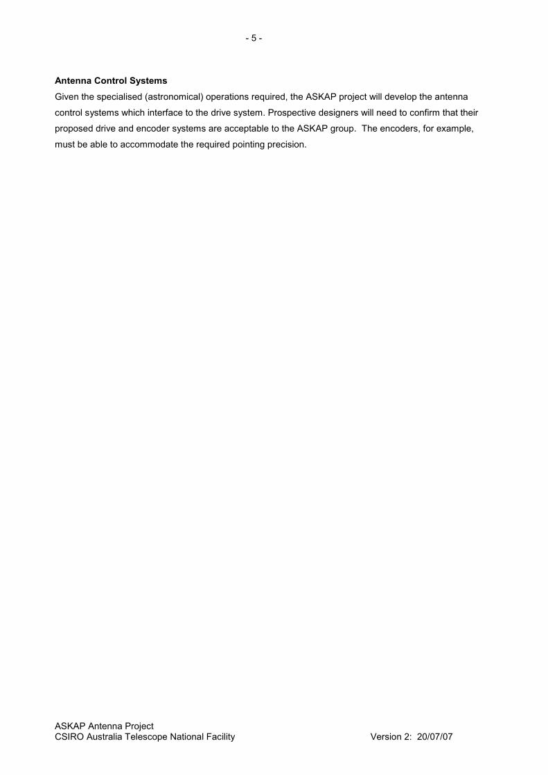
Figure – NASA JPL 34-m DSN antenna with monopod feed support.
Most radio telescopes have adopted an "alt-az" mount. However, this type of mount is not necessarily the
best choice from the perspective of achieving the highest dynamic range imaging. This becomes even truer
with the increasing complexity of imaging technology and the requirement to model (time-variable) sidelobe
responses.
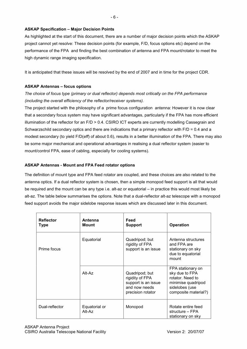
The Westerbork Array antennas, built in the late 1960's, are recognised as demonstrating the benefits of
equatorial mounts (i.e. excellent dynamic range imaging).
Figure – Equatorial mount Westerbork array antennas (www.astron.nl)
- 8 -
ASKAP Antenna Project CSIRO Australia Telescope National Facility Version 2: 20/07/07
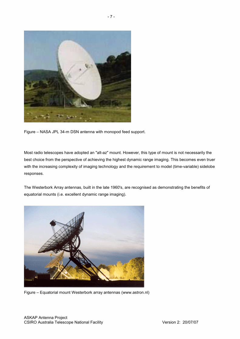
Conventional wisdom has it that the alt-az mount is significantly cheaper to build, and combined with the
capability of delivering all sky coverage the alt-az has become the mount of choice for radio telescopes
(e.g. the Australia Telescope Compact Array at Narrabri (ATCA) ).
Figure – alt-az mount ATCA antenna (www.atnf.csiro.au)
The choice of mount for ASKAP needs to be carefully considered – we are investigating whether critical
technologies have evolved to the point that the potential costs and benefits for the mount decision need to
be recast.
Impact of the sidelobe response on imaging
An antenna's response to a distant transmitter (source) depends on the orientation of the source relative to
the antenna's main axis. The response function is called the beam pattern; it consists of a main beam - the
response when the source is near boresight, and the sidelobes, the low level responses when the antenna
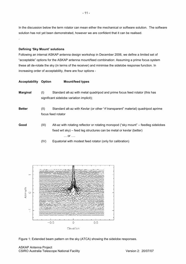
is pointing away from the source. Figure 1 shows the beam pattern for the ATCA 22m antenna. The plot
was obtained by executing a set of raster scans centred on a geostationary satellite. We see a strong
response on boresight; there is also a circular sidelobe around the main beam, whose peak is about 3% of
boresight. And there are a number of weaker circular sidelobes at larger radii. These all relate to the
general symmetry of the reflector. In addition, there are two linear sidelobe structures, one vertical, one
horizontal, which are the sidelobes due to the quadripod structure.
The following outlines one approach to calculating the full beam pattern -
1. Invoke the Reciprocity Theorem which shows that the radiation patterns for receive and transmit are
identical.
2. Launch a wave from the feed horn and follow its progress to the reflector and then out into space. In
this way we can account for all the obstacles in the path - diffraction around, and blockage by the quadripod
legs and any structure in the focal plane.
- 9 -
ASKAP Antenna Project CSIRO Australia Telescope National Facility Version 2: 20/07/07
It is useful to take a snapshot of the progress at the aperture plane - the plane parallel to the plane defined
by the rim of the main reflector, positioned just above the focus. The far-field pattern is obtained from a
Fourier transform of the aperture plane distribution.
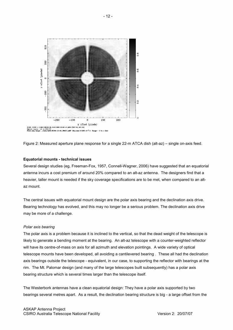
Figure 2 shows the aperture plane distribution for the 22m ATCA antenna with a single pixel receiver. The
main features are:
1. A symmetrical "pill-box" distribution. This is the dominant feature which provides the main beam. The
transform of a "pill box" is a Bessel function J1(r)/r, with a strong central peak, followed by sidelobes which
decrease gradually in strength as a function of the radial distance
2. A central blockage due to the 2.8m sub-reflector. This provides an additional set of circular sidelobes.
3. Blockage shadows of the quadripod legs. These shadows come in two flavours:
a) The inner section, where rays from the feed hit the underside of the quadripod legs after
reflection from the main reflector. These shadows are rectangular in appearance. This section
extends from the edge of the subreflector blockage out to the point where the quadripod leg
attaches to the main reflector surface.
b) The outer section, where the rays hit the underside of the quadripod and are prevented from
reaching the reflector. This section extends from the end of the inner section out to the rim of the
main reflector. This shadow is far from rectangular: it flares out at the main reflector rim.
The Fourier transform of the aperture plane is the sum of the transform of each component - items 1, 2 and
3. The magnitude of the quadripod sidelobes is set by the area of the blockage shadows scaled to the 22m
reflector area. Fat, opaque legs produce significant sidelobes; transparent, or very narrow legs have faint
sidelobes. The requirement for high-dynamic range images with the ATCA has led us to implement
complex corrections in the imaging software.
It is important to note that the sidelobes are related to the location of the receiving element with respect to
the antenna structures – in the case of ASKAP with FPA receivers, each made up of N x N elements, each
element will see the quadripod legs from a different angle, leading to different shadowing.
Basic theory of radio astronomical imaging (interferometry)
We observe a celestial target (field) for a period of time, T, with an array of N antennas. The data collected
will consist of all the cross-correlations between all the antennas in the array.
∫+
−=
τ
τ
t
tdttjVtiVtjiC ),(),(),,(
- 10 -
ASKAP Antenna Project CSIRO Australia Telescope National Facility Version 2: 20/07/07
is the correlation between antennas (i) and (j) at time t, averaged over a small interval (2.
The imaging process, which is achieved with a 2-dimensional Fourier transform, in effect looks for the
signature of all the possible point sources in the field. This will work well as long as the system is stable
and calibrated. A source offset from the field centre will appear with an intensity related to its position in the
full beam pattern. In an ideal world the beam pattern's sidelobes are all concentric circles centred on the
boresight, and the offset sources will appear with constant amplitude, and will image correctly. In the real
world there will be linear shadows and non-circular sidelobes. As a result the imaging process will be
imperfect, with artefacts generated by the apparent gain fluctuations. The magnitude of the artefacts will be
related to the magnitude of these non-linear sidelobes, and temporal variations due to field rotation in these
exacerbates the difficulty of calibration.
A number of strategies have been suggested to address this problem and the two simplest options are
either to use
- RF transparent quadripod legs, to eliminate the sidelobes, or
- equatorial antenna mount to lock the sidelobes to the sky, to eliminate the apparent variation in amplitude,
or
- rotate monopod feed support.
These, and other options, are discussed in more detail in the following sections.
The case for ‘Sky Mount’ antennas
The simplest (and traditional) implementation of a ‘sky mount’ antenna is one using an equatorial mount.
This fixes the relationship between the pattern of the receiver “pixels” and the sky, so that there is no
rotation of the field as it is tracked across the sky. To the receiver, the sky and the feed mount (i.e.
quadripod) will be stable on the sky.
The data processing pipeline is predicated on the presence of some form of stabilisation of the focal plane
with respect to the sky, so that the processor is presented with N data streams, from N beams fixed on the
sky. The image quality is dependent on the quality of those data streams. Ideally, no source should exhibit
temporal variations, irrespective of where it is in the synthesised (by the beamformer) antenna primary
beam. The advantage of the sky mount is that it minimizes such temporal variations, which greatly
simplifies the data processing process. The equatorial mount does this by the nature of its geometry, and
minimizes the need for additional compensating mechanisms or software. It is possible that a
feed rotator may still be desirable on an equatorial mount telescope, but it would only be used for
calibration and thus have a lower drive specification.
With an alt-azimuth mount the sky rotates with respect to the antenna, so some form of image stabilisation
is required, either as a virtual rotator (via software in the beamformer) or a mechanical rotator. The software
rotator may be highly complex, costly and may have significant issues regarding calibration.
- 11 -
ASKAP Antenna Project CSIRO Australia Telescope National Facility Version 2: 20/07/07
In the discussion below the term rotator can mean either the mechanical or software solution. The software
solution has not yet been demonstrated, however we are confident that it can be realised.
.
Defining ‘Sky Mount’ solutions
Following an internal ASKAP antenna design workshop in December 2006, we define a limited set of
“acceptable” options for the ASKAP antenna mount/feed combination: Assuming a prime focus system
these all de-rotate the sky (in terms of the receiver) and minimise the sidelobe response function. In
increasing order of acceptability, there are four options -
Acceptability Option Mount/feed types
Marginal (I) Standard alt-az with metal quadripod and prime focus feed rotator (this has
significant sidelobe variation implicit);
Better (II) Standard alt-az with Kevlar (or other “rf transparent” material) quadripod aprime
focus feed rotator
Good (III) Alt-az with rotating reflector or rotating monopod (“sky mount” – feedleg sidelobes
fixed wrt sky) – feed leg structures can be metal or kevlar (better)
… or ….
(IV) Equatorial with modest feed rotator (only for calibration)
Figure 1: Extended beam pattern on the sky (ATCA) showing the sidelobe responses.
- 12 -
ASKAP Antenna Project CSIRO Australia Telescope National Facility Version 2: 20/07/07
Figure 2: Measured aperture plane response for a single 22-m ATCA dish (alt-az) – single on-axis feed.
Equatorial mounts - technical issues
Several design studies (eg, Freeman-Fox, 1957, Connell-Wagner, 2006) have suggested that an equatorial
antenna incurs a cost premium of around 20% compared to an alt-az antenna. The designers find that a
heavier, taller mount is needed if the sky coverage specifications are to be met, when compared to an alt-
az mount.
The central issues with equatorial mount design are the polar axis bearing and the declination axis drive.
Bearing technology has evolved, and this may no longer be a serious problem. The declination axis drive
may be more of a challenge.
Polar axis bearing
The polar axis is a problem because it is inclined to the vertical, so that the dead weight of the telescope is
likely to generate a bending moment at the bearing. An alt-az telescope with a counter-weighted reflector
will have its centre-of-mass on axis for all azimuth and elevation pointings. A wide variety of optical
telescope mounts have been developed, all avoiding a cantilevered bearing . These all had the declination
axis bearings outside the telescope - equivalent, in our case, to supporting the reflector with bearings at the
rim. The Mt. Palomar design (and many of the large telescopes built subsequently) has a polar axis
bearing structure which is several times larger than the telescope itself.
The Westerbork antennas have a clean equatorial design: They have a polar axis supported by two
bearings several metres apart. As a result, the declination bearing structure is big - a large offset from the

- 13 -
ASKAP Antenna Project CSIRO Australia Telescope National Facility Version 2: 20/07/07
polar axis is needed to ensure that the reflector does not foul the polar axis structure when pointing towards
sources significantly south of the celestial equator. The figure below illustrates the layout.
Figure: Typical equatorial mount design
Wind loading is an additional force that has to be supported by the main bearing; the torque at the bearing
cannot be cancelled with a counterweight. This may lessen the advantage of this mount, depending on the
relative magnitudes of dead-weight and wind loading.
The drive machinery on the polar axis is an additional problem: the loads are heavier than is the case for
an alt-az antenna. Unless there is a counterweight the weight of the reflector will lead to an hour angle
dependent moment that the drive system will need to support.
Declination axis drive
The problem with the declination axis drive is the large range of angles that we need to accommodate -
roughly +/- 90 degrees. This is more than is comfortably provided by a jack-screw mechanism. For
comparison, the elevation drive needs less than 90 degrees. This has meant, in previous equatorial
designs, that a 180 degree bull-gear of large diameter is required.
Counterweights
Counterweighting an antenna has advantages and disadvantages. It allows the drive system in the relevant
axes to use less power (other than for acceleration, where the increased rotational inertia requires more
power), and be under less continuous strain when compared with unbalanced systems. The additional
power consumption to move unbalanced systems can be a significant cost over the operating life of the
telescope. In addition, unbalanced systems are potentially more dangerous if a critical part of the drive
- 14 -
ASKAP Antenna Project CSIRO Australia Telescope National Facility Version 2: 20/07/07
system fails, with more serious runaway consequences possible. The disadvantage of counterweighted
systems is the cost of the additional, “dead” material that increases weight, bearing loads, etc.
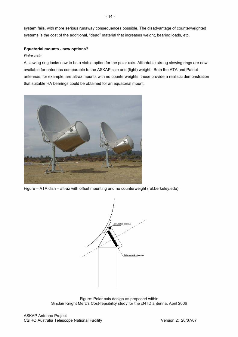
Equatorial mounts - new options?
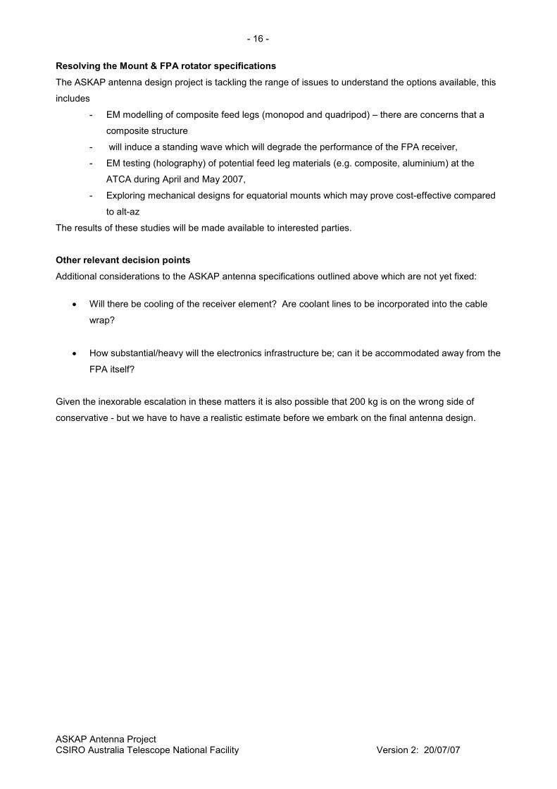
Polar axis
A slewing ring looks now to be a viable option for the polar axis. Affordable strong slewing rings are now
available for antennas comparable to the ASKAP size and (light) weight. Both the ATA and Patriot
antennas, for example, are alt-az mounts with no counterweights; these provide a realistic demonstration
that suitable HA bearings could be obtained for an equatorial mount.
Figure – ATA dish – alt-az with offset mounting and no counterweight (ral.berkeley.edu)
Figure: Polar axis design as proposed within Sinclair Knight Merz’s Cost-feasibility study for the xNTD antenna, April 2006

- 15 -
ASKAP Antenna Project CSIRO Australia Telescope National Facility Version 2: 20/07/07
FPA Feed Rotators
As noted previously, some form of focal plane rotator is almost certainly required independent of whichever
antenna mount type is adopted. A mechanical feed rotator will need to meet the following specifications:
• To support a load of 200 kg
• Shape: circular
• Access from above is required
• Rotation required : +/- 190 degrees.
• Positioning precision: 0.1 degrees
• A cable wrap is required.
A possible implementations for a mechanical feed rotator is shown below.
Figure: Feed Rotator “Model 1” Assuming that the FPA is light weight, and symmetrical, no significant safety measures are required - a
simple brake on the motor will be adequate.
- 16 -
ASKAP Antenna Project CSIRO Australia Telescope National Facility Version 2: 20/07/07
Resolving the Mount & FPA rotator specifications
The ASKAP antenna design project is tackling the range of issues to understand the options available, this
includes
- EM modelling of composite feed legs (monopod and quadripod) – there are concerns that a
composite structure
- will induce a standing wave which will degrade the performance of the FPA receiver,
- EM testing (holography) of potential feed leg materials (e.g. composite, aluminium) at the
ATCA during April and May 2007,
- Exploring mechanical designs for equatorial mounts which may prove cost-effective compared
to alt-az
The results of these studies will be made available to interested parties.
Other relevant decision points
Additional considerations to the ASKAP antenna specifications outlined above which are not yet fixed:
• Will there be cooling of the receiver element? Are coolant lines to be incorporated into the cable
wrap?
• How substantial/heavy will the electronics infrastructure be; can it be accommodated away from the
FPA itself?
Given the inexorable escalation in these matters it is also possible that 200 kg is on the wrong side of
conservative - but we have to have a realistic estimate before we embark on the final antenna design.
- 17 -
ASKAP Antenna Project CSIRO Australia Telescope National Facility Version 2: 20/07/07
Further Project Information & Contacts
ASKAP – the large-Number small-diameter antenna Array is a new radio telescope to be built in WA from
2008 onwards.
Up-to-date information on ASKAP can be found at www.atnf.csiro.au
CSIRO Australia Telescope National Facility Cnr Vimiera & Pembroke Roads Marsfield NSW 2122 Postal: PO Box 76 EPPING NSW 1710 Tel: +61 (0) 2 9372 4100 ATNF Director, and SKA Director, Australia Dr Brian Boyle ATNF Assistant Director – ASKAP & SKA Phase I Project Leader Dr David Deboer ASKAP Antenna Project personnel
Carole Jackson ([email protected]) Mike Kesteven ([email protected]) Ross Forsyth ([email protected])