Embed Size (px)
Citation preview
8/20/2019 ASHRAE Journal - How to Design & Control Waterside Economizers-Taylor
http://slidepdf.com/reader/full/ashrae-journal-how-to-design-control-waterside-economizers-taylor 1/7
A S H RA E J O U RN A L a s h r a e . or g J U N E 2 0 1 43 0
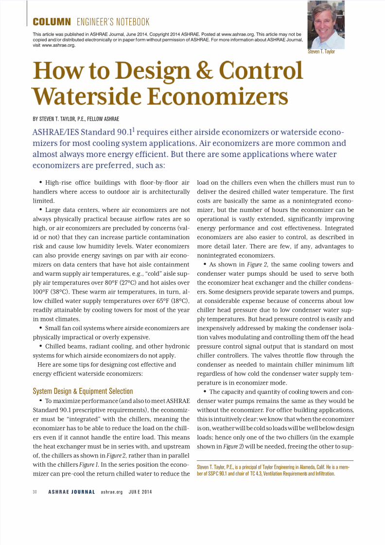
COLUMN ENGINEER’S NOTEBOOK
Steven T. Taylor
Steven T. Taylor, P.E., is a principal of Taylor Engineering in Alameda, Calif. He is a mem-ber of SSPC 90.1 and chair of TC 4.3, Ventilation Requirements and Infiltration.
BY STEVEN T. TAYLOR, P.E., FELLOW ASHRAE
• High-rise office buildings with floor-by-floor air
handlers where access to outdoor air is architecturallylimited.
• Large data centers, where air economizers are not
always physically practical because airflow rates are so
high, or air economizers are precluded by concerns (val-
id or not) that they can increase particle contamination
risk and cause low humidity levels. Water economizers
can also provide energy savings on par with air econo-
mizers on data centers that have hot aisle containment
and warm supply air temperatures, e.g., “cold” aisle sup-
ply air temperatures over 80°F (27°C) and hot aisles over
100°F (38°C). These warm air temperatures, in turn, al-
low chilled water supply temperatures over 65°F (18°C),
readily attainable by cooling towers for most of the year
in most climates.
• Small fan coil systems where airside economizers are
physically impractical or overly expensive.
• Chilled beams, radiant cooling, and other hydronic
systems for which airside economizers do not apply.
Here are some tips for designing cost effective and
energy efficient waterside economizers:
System Design & Equipment Selection • To maximize performance (and also to meet ASHRAE
Standard 90.1 prescriptive requirements), the economiz-
er must be “integrated” with the chillers, meaning the
economizer has to be able to reduce the load on the chill-
ers even if it cannot handle the entire load. This means
the heat exchanger must be in series with, and upstream
of, the chillers as shown in Figure 2, rather than in parallel
with the chillers Figure 1. In the series position the econo-
mizer can pre-cool the return chilled water to reduce the
load on the chillers even when the chillers must run to
deliver the desired chilled water temperature. The firstcosts are basically the same as a nonintegrated econo-
mizer, but the number of hours the economizer can be
operational is vastly extended, significantly improving
energy performance and cost effectiveness. Integrated
economizers are also easier to control, as described in
more detail later. There are few, if any, advantages to
nonintegrated economizers.
• As shown in Figure 2, the same cooling towers and
condenser water pumps should be used to serve both
the economizer heat exchanger and the chiller condens-
ers. Some designers provide separate towers and pumps,
at considerable expense because of concerns about low
chiller head pressure due to low condenser water sup-
ply temperatures. But head pressure control is easily and
inexpensively addressed by making the condenser isola-
tion valves modulating and controlling them off the head
pressure control signal output that is standard on most
chiller controllers. The valves throttle flow through the
condenser as needed to maintain chiller minimum lift
regardless of how cold the condenser water supply tem-
perature is in economizer mode. • The capacity and quantity of cooling towers and con-
denser water pumps remains the same as they would be
without the economizer. For office building applications,
this is intuitively clear: we know that when the economizer
is on, weather will be cold so loads will be well below design
loads; hence only one of the two chillers (in the example
shown in Figure 2) will be needed, freeing the other to sup-
This article was published in ASHRAE Journal, June 2014. Copyright 2014 ASHRAE. Posted at www.ashrae.org. This article may not becopied and/or distributed electronically or in paper form without permission of ASHRAE. For more information about ASHRAE Journal,visit www.ashrae.org.

8/20/2019 ASHRAE Journal - How to Design & Control Waterside Economizers-Taylor
http://slidepdf.com/reader/full/ashrae-journal-how-to-design-control-waterside-economizers-taylor 2/7
J U N E 2 0 1 4 a s h r a e . or g A S H RA E J O U RN A L 3 1
ply tower water to the economizer heat exchanger. But this
is also true for data centers where the load may require all
chillers to run even in cold weather. The reason is that the
load on the towers is actually reduced by the economizer
since compressor heat is reduced, and condenser water
flow to the chiller condensers may be less than design be-
cause it is colder (and in fact may be reduced by the throt-
tling of the head pressure control valves discussed earlier),
making water available to the economizer heat exchanger
without the need to add pumps.
• While cooling tower capacity is not affected by the
economizer, it may be necessary to reduce the designapproach temperature to meet Standard 90.1 Section
6.5.1.2.1 waterside economizer requirements, particu-
larly for plants with high loads in cold weather. This is
discussed further in the sidebar, “Example Design Pro-
cedure” (Page 34).
• It is critical that cooling towers be very efficient since
they will be running at full speed many hours of the year.
A minimum of 90 gpm/hp (7.6 L[s·kW]) at Standard 90.1
conditions (95°F to 85°F at 75°F [35°C to 29°C at 24°C] wet
bulb) is recommended for office type applications and 110
gpm/hp (9.3 L[s·kW]) for 24/7 applications such as data
centers. These efficiencies are 10% above those shown to
be cost effective for non-economizer applications.2
• Cooling towers should be selected so that as many
tower cells as possible can be enabled when the econo-
mizer is enabled to maximize efficiency and capacity
while maintaining minimum flow rates required by the
tower manufacturer to prevent scaling. Low minimum
flow rates can be achieved using weir dams and special
nozzles in the hot water distribution pans.
• Chilled water pump head increases due to the pres-
sure drop of the heat exchanger when in economizermode. However, in applications such as offices where
the loads are low when the economizer is on, pump head
may not need to increase above design head when the
economizer is off; excess head may be available for the
heat exchanger when the economizer is active due to the
reduced chilled water flow to coils.
• The heat exchanger should be a plate & frame type and
selected for an approach of about 3°F (1.7°C) (i.e., the tem-
perature of the chilled water leaving the heat exchanger is
equal to 3°F (1.7°C) above the temperature of the condenser
FIGURE 1 Nonintegrated economizer.
Cooling Tower 1 Cooling Tower 2
Chiller 1
Chiller 2
Plate and FrameHeat Exchanger Minimum Chiller
Flow Bypass
FIGURE 2 Integrated economizer.
Cooling Tower 1 Cooling Tower 2
Plate and FrameHeat Exchanger
Chiller 1
Chiller 2
Modulating
Valve
BypassWSE-Only
Minimum ChillerFlow Bypass

8/20/2019 ASHRAE Journal - How to Design & Control Waterside Economizers-Taylor
http://slidepdf.com/reader/full/ashrae-journal-how-to-design-control-waterside-economizers-taylor 3/7
Adverti sement formerl y in this space.

8/20/2019 ASHRAE Journal - How to Design & Control Waterside Economizers-Taylor
http://slidepdf.com/reader/full/ashrae-journal-how-to-design-control-waterside-economizers-taylor 4/7
J U N E 2 0 1 4 a s h r a e . or g A S H RA E J O U RN A L 3 3
water entering the heat exchanger).
Heat exchanger cost increases expo-
nentially with approach temperature
so very close approaches should be
tested for cost effectiveness. The heat
exchanger pressure drop on the con-
denser water side should be similar to
that of the condensers so the flow rate
will be similar when serving either
the condensers or heat exchanger.
On the chilled water side, pressure
drop is typically limited to about 5 or
6 psi (34 or 41 kPa) to limit the chilled
water pump energy impact. The heat
exchanger performance must be cer-
tified per AHRI Standard 4003 as re-quired by Standard 90.1.
• To maximize economizer perfor-
mance, and also performance of the
system even when not on economizer,
the chilled water system must be de-
signed for a very high temperature
rise (∆T ). This maximizes the chilled
water return temperature which al-
lows the economizer to operate more
hours. The design procedure is sim-
ple: all cooling coils should be the larg-
est they can be within the cleanability
limitations of Standard 62.1,4 which
requires that dry coil pressure drop at
500 fpm (2.5 m/s) face velocity must
not exceed 0.75 in. w.c. (188 Pa).* This
will typically be an eight row coil with
about 12 fins per inch (5 fins per cm).
Using high ∆T coils also reduces first
costs, energy demand, and annual
energy costs and should be used forall designs5 but especially those with
waterside economizers.
Waterside Economizer ControlsControl systems for waterside
economizer are generally the same
as for conventional plants except
they require one added sensor that
is optional on conventional plants: a
wet-bulb temperature sensor. This is
usually a combination temperature
and relative humidity sensor with
software or electronics that converts
the two signals to wet-bulb tem-
perature. Unfortunately, humidity
sensors are notoriously unreliable
and require frequent recalibration.
To improve reliability it is essential
to specify a high quality sensor (seeReference 8 for recommendations)
and also provide a quality check by
having the control system compare
local dew-point temperature to the
dew-point temperature data mea-
sured at the nearest National Oceanic
and Atmospheric Administration
(NOAA) site via the Internet. If the
local dew-point temperature (calcu-
lated from the wet-bulb temperature
using psychrometric routines stan-
dard in most digital control systems)
substantially differs from the NOAA
dew-point temperature, alarms can
be generated indicating a need for
humidity sensor recalibration.
Recommended control sequences
for waterside economizers:‡
• Reset chilled water supply tem-
perature setpoint based on valve de-
mand, i.e., raise the water tempera-ture until one chilled water control
valve is full wide open.§
*Here is a simple way to test a coil for Standard 62.1 compliance with a manufacturer’s coil selection program: Start with the desiredcoil including desired rows, fin type, and fin density; adjust the airflow rate up or down until the face velocity is 500 fpm (9 km/h);reduce the entering drybulb temperature to 60ºF (15ºC) to ensure a dry coil; then run the selection. To comply, the pressure drop underthese conditions must be 0.75 in. w.c. (188 Pa) or less.‡Time delays required to prevent rapid mode changes are required but not included here for clarity.§Many engineers have concerns about the impact of CHWST reset on humidity control. When the waterside economizer is active, outdoorair is cool so humidity should not be a concern. But if the reset logic is based on chilled water valve position, CHWST reset will never have asignificant impact on space humidity control regardless of weather. This is because space humidity is a function of the supply air humidityratio which in turn is a function of the coil leaving dry-bulb temperature setpoint. Regardless of CHWST, the air leaving a wet coolingcoil is nearly saturated; lowering CHWST only slightly reduces supply air humidity ratio. So as long as the supply air temperature can bemaintained at the desired setpoint, which resetting off valve position ensures, resetting CHWST will not impact space humidity.
Adverti sement formerl y in this space.

8/20/2019 ASHRAE Journal - How to Design & Control Waterside Economizers-Taylor
http://slidepdf.com/reader/full/ashrae-journal-how-to-design-control-waterside-economizers-taylor 5/7
A S H RA E J O U RN A L a s h r a e . or g J U N E 2 0 1 43 4
• Enable the economizer if the chilled water return
temperature is greater than the predicted heat exchang-
er leaving water temperature (PHXLWT) plus 2°F (1.1°C). The 2°F (1.1°C) differential is needed to avoid expending
a lot of cooling tower fan energy for only minimal econo-
mizer load reduction. PHXLWT is estimated using the
equation:
PHXLWT = T WB + PA HX + PA CT
PA HX = DA HX × PLR HX
PA CT = m × ( DT WB – T WB) + DA CT
where
T WB
= current wet-bulb temperature
PA HX = predicted heat exchanger approach
PA CT = predicted cooling tower approach
DA HX = design heat exchange approach PLR HX = predicted heat exchanger part-load ratio
(current chilled water flow rate divided by
design HX chilled water flow rate)
DT WB = design wet-bulb temperature
DA CT = design cooling tower approach
m = slope developed from the manufacturer’s
cooling tower selection program or empiri-
cally after the plant is operational. Typical
values are 0.2 to 0.5 for near constant load
applications like data centers. For office
1. Calculate the chilled water load at50°F (10ºC) dry-bulb temperature and45°F (7.2ºC) wet-bulb temperature.
This is the performance test conditionprescribed by Standard 90.1 for build-ings other than data centers.† This canbe done using standard load calculationsoftware by selecting a spring or fallmonth and overriding design outdoor airtemperatures. All other load assumptionsremain the same. Loads should be re-duced from design loads due to reducedconduction and outdoor air conditioningloads.
2. Use coil selection software or othercoil models to determine the warmestchilled water supply temperature thatcan meet 100% of the chilled water loaddetermined above for all coils. To do this,first determine the warmest supply watertemperature that can meet the load at thedesign flow for each coil, then select thecoldest of these and use it to determinethe chilled water flow through all the othercoils. The coil software will also determinethe chilled water return temperature fromeach coil. Typically, the chilled water sup-ply temperature can be reset 5ºF (3ºC) ormore above the design chilled water sup-ply temperature. This can be true even fordata centers despite the consistently highload by taking advantage of redundant air
handlers to effectively increase availablecoil area.
3. Select the condenser water flow rateequal to a multiple of design condenserwater pump flow rates as required toclosely match the chilled water flow ratedetermined above.
TABLE 1 Chiller design conditions (each).
ChilledWater Side
CondenserWater Side
CAPACITY, TONS 300 345
FLOW, GPM 290 550
ENTERING WATER, °F 69 75
LEAVIN G WATER, °F 44 90
DP , PSI 6.5 6.7
TABLE 2 Waterside economizer heat exchanger
design conditions.Chilled Water
(Hot) SideCondenser Water
(Cold) Side
TOTAL LOAD, TONS 350 350
FLOW, GPM 560 550
ENTERING WATER, °F 65 47.0
LEAVIN G WATER, °F 50 62.3
DP , PSI 5 4.8
†Data center performance test conditions vary by climate zone. See Standard 90.1, Table 6.5.1.2.1 for details.
Example Design Procedure6,7
4. Determine the heat exchanger condenserwater supply temperature equal to the re-quired reset chilled water supply temperature
determined above less the 3ºF (1.7ºC) ap-proach temperature.
5. Calculate the condenser water return
temperature to match the chilled water loadbased on the condenser water flow and sup-ply temperature determined above.
6. Use cooling tower selection software toverify that the cooling towers can provide therequired condenser water supply temperatureat 45ºF (7ºC) wet-bulb temperature. If not,
then cooling towers (and/or heat exchang-ers) will need to be reselected for closerapproach temperatures.
Example. Assume the plant in Figure 2
served an office building with floor-by-
floor air handlers. The design conditions ofthe two chillers at the design cooling peakare shown in Table 1. The pump flow ratesmatch the chiller design rates and coolingtowers were selected at 68ºF (20ºC) wet-bulb temperature, a 7ºF (3.9ºC) approach.The cooling loads were then recalculatedat 50ºF/45ºF (10ºC/7.2ºC) outdoor airtemperature conditions; the load dropsfrom 600 tons to 350 tons (2110 kW to1231 kW). Coil selection programs werethen used to determine the chilled waterconditions required at the air handlers,and condenser water conditions weredetermined using the steps above. The
resulting heat exchanger design condi-tions are shown in Table 2.
Then, cooling tower selection soft-ware was used to see if the selectedcooling towers could cool 550 gpm (35L/s) (275 gpm (17.5 L/s) across eachtower) from 62.3ºF (16.8ºC) to 47ºF(8.3ºC), a 2ºF (1.1ºC) approach to the45ºF (7.2ºC) wet bulb temperature. But,the software indicated that the towerswere only able to deliver 48ºF (8.9ºC).So, the towers had to be reselected for a73ºF (22.8ºC) leaving water temperature(5ºF/2.8ºC approach to design wet-bulbtemperature) to achieve a 2ºF (1.1ºC)
approach at the conditions above. Notethat heat exchanger approach also couldhave been reduced to deliver the desiredchilled water temperature, but it is usu-ally more cost effective to invest in largercooling towers since they also improveefficiency when the economizer is off.
COLUMN ENGINEER’S NOTEBOOK

8/20/2019 ASHRAE Journal - How to Design & Control Waterside Economizers-Taylor
http://slidepdf.com/reader/full/ashrae-journal-how-to-design-control-waterside-economizers-taylor 6/7
J U N E 2 0 1 4 a s h r a e . or g A S H RA E J O U RN A L 3 5
type applications, m is typically in the range
–0.2 to 0.
• Disable the waterside economizer if it is not reduc-
ing the chilled water return temperature by at least 1°F
(0.6°C).
• Disable chillers when HXLWT is at or below the de-
sired chilled water supply temperature setpoint.
• Enable chillers when chilled water supply tempera-
ture is greater than desired setpoint. Note that multiple
chillers may need to be enabled if the current chilled wa-
ter flow is well above the design flow of a single chiller.
• Run as many tower cells as tower minimum flow
limits will allow.
• Control condenser water flow to roughly match the
current chilled water flow but reduce flow (within tow-
er minimum flow constraints) as needed to maintain aminimum 5°F (2.8°C) range. The lower flow and higher
range improves tower efficiency and reduces pump pow-
er. Flow can be controlled by staging pumps, modulat-
ing speed on variable speed pumps, and/or modulating
isolation valves on the heat exchanger. Flow rate can be
measured directly with a flow meter (full bore magnetic
or ultrasonic type are recommended to prevent fouling)
or deduced from heat exchanger pressure drop.
• Tower speed control:
1. When waterside economizer is disabled: Control
speed to maintain normal condenser water tempera-
tures which should be reset from load or wet-bulb tem-
perature.9
2. When waterside economizer and chillers are en-
abled: Run tower fans at 100% speed.
3. When chillers are disabled: Control speed to
maintain HXLWT at desired chilled water supply tem-
perature setpoint.
The only complex sequence above is predicting when
the economizer should be enabled. Fortunately, if the
prediction calculation is off and the economizer isenabled prematurely, it will shortly be disabled and
the plant will see no disruptions in chilled water flow
or supply temperature. This contrasts with noninte-
grated economizers where switching from economizer
to chillers can be disruptive and guessing wrong about
Adverti sement formerly in this space.

8/20/2019 ASHRAE Journal - How to Design & Control Waterside Economizers-Taylor
http://slidepdf.com/reader/full/ashrae-journal-how-to-design-control-waterside-economizers-taylor 7/7
A S H RA E J O U RN A L a s h r a e . or g J U N E 2 0 1 43 6
economizer performance can result in chiller short
cycling and temporary loss of chilled water supply tem-
perature control.
Conclusions Waterside economizers are preferred to airside
economizers in some applications despite being
less energy efficient. When waterside economizers
are used, they usually require only the addition of
a heat exchanger between the condenser water and
chilled water; other components remain the same,
although cooling tower approach sometimes must
be reduced to meet Standard 90.1 performance
requirements. Economizers should always be piped
in an integrated (series) arrange-
ment. Controls are straightfor-
ward except predicting when the
economizer should be enabled
which requires knowledge of wet-
bulb temperature and predicted
heat exchanger and cooling tower
approaches. But with integrated
economizer design, this predic-tion is not critical to reliable plant
performance.
References1. ASHRAE/IES Standard 90.1-2013, Energy
Standard for Buildings Except Low-Rise Residential
Buildings.
2. Taylor, S. 2012. “Optimizing the design
and control of chilled water plants, part 4:
chiller & cooling tower selection.” ASHRAE
Journal, March.
3. AHRI 400-2001, Liqui d-to -Liq uid Heat Exchangers.
4. ASHRAE Standard 62.1-2010,Ventilation for
Acceptable Indoor Air Quality.
5. Taylor, S. 2011. “Optimizing the design
and control of chilled water plants part 3:
pipe sizing and optimizing ∆T .” ASHRAE Jour-
nal December.
6. Stein, J. 2009. “Waterside economizing
in data centers: design and control consider-
ations.” ASHRAE Transactions 115(2).
7. Stein, J., S. Taylor. 2013. “Seminar 21:
Water Side Economizers, a.k.a. Free Cooling,
Integrated Water Side Economizer.” ASHRAE Annual Conference.
8. NBCIP. 2005. “Supplement Product
Test ing Repor t: Duc t-Mounted Relat ive
Humidity Transmitters.” http://tinyurl.com/
of6leku.
9. Taylor, S. 2012. “Optimizing the design
and control of chilled water plants, part 5:
optimized control sequences.” ASHRAE Journal
June.
COLUMN ENGINEER’S NOTEBOOK
Adverti sement formerly in this space.