Embed Size (px)
Citation preview

ASHE and AHARequest for Proposals
Energy to Care Program Expansion
*All responses are due by 5:00 pm CT on June 22, 2018.
1
Table of Contents
1. Introduction ...................................................................................................................................... 2 1 Purpose .......................................................................................................................................... 2 1.2 Background .................................................................................................................................. 3
2. Schedule of Events .......................................................................................................................... 4
3. Proposal Format Guidelines ........................................................................................................... 4 3.1 Cover letter .................................................................................................................................. 5 3.2 Summary of qualifications ............................................................................................................ 5 3.3 Technology features and implementation plan ............................................................................ 5 3.4 Cost proposal ............................................................................................................................. 6 3.5 Staffing......................................................................................................................................... 7 3.6 Protections and assurances ......................................................................................................... 7
4. Proposal Submission and Eligibility .............................................................................................. 8 4.1 Eligibility ...................................................................................................................................... 8 4.2 Preparation .................................................................................................................................. 8 4.3 Submission and due date ............................................................................................................. 8 4.4 Inquiries ....................................................................................................................................... 8 4.5 Proposal validity ........................................................................................................................... 8 4.6 Modification and withdrawal ......................................................................................................... 9 4.7 Right to Revise or Cancel the RFP: .............................................................................................. 9 4.7 Right to reject proposals .............................................................................................................. 9 4.8 Confidential material ................................................................................................................. 10 4.9 Terms and conditions ................................................................................................................ 10
5. Evaluation and Selection Criteria ................................................................................................. 10 5.1. Evaluation method .................................................................................................................... 10 5.2. Point-scoring method ................................................................................................................ 11
6. Scope of Work ................................................................................................................................ 13 6.1 Technology capabilities .............................................................................................................. 13 6.2. IT Requirements ....................................................................................................................... 17 6.3. Technical warranty, support, and training .................................................................................. 19 6.4. Testing and commissioning ....................................................................................................... 19
Glossary of Terms ............................................................................................................................. 20
Appendix A: Table of Metering and Gateway requirements ........................................................... 21
Appendix B: Visualization Charts: General Guidance .................................................................... 22
Appendix C: Informational Architecture for Data Acquisition ........................................................ 23
Appendix D. Pilot Sites Characteristics ........................................................................................... 24

2
1. Introduction
The American Society for Healthcare Engineering (“ASHE”), a professional membership group of the American Hospital Association (“AHA”) and the AHA are issuing this Request for Proposal (“RFP”) soliciting proposals for qualified companies to help develop and implement an Energy Information System (“EIS”) solution for the AHA and ASHE members (collectively, the “Association”). The development and implementation of the EIS are expected to begin following the vendor selection, or as soon thereafter as directed by the Association.
1 Purpose
The Association is soliciting proposals for qualified companies to help develop and implement an Energy Information System (EIS) solution to be owned by the Association that includes:
1) An EIS software solution: that consolidates and displays energy data it had received fromvarious sources, through an interactive graphic user interface for Association members toconduct building energy benchmarking and enable optimizing energy performance in theirhealth care facilities. The new EIS tool will be utilized to expand the Energy to Care programand bring greater value to Association members. The EIS solution receives energy consumptiondata by way of input from meters located throughout the healthcare facility. The solutionprovides a method of gathering data and translating the data into a dashboard tool.
2) An EIS package: comprising necessary new metering integrated with any legacy hardware,communications gateway; and the software platform described in (1) above; system training;ongoing maintenance and support for 3 pilot sites identified by Association.
i. An EIS package will provide graphical representation of energy use for the users based onreal time energy metering data. Sample dashboards can be found in Appendix B of thisRFP.
ii. EIS package will be implemented in three (3) pilot facilities. It is anticipated that the pilotfacilities will be of the following characteristics: Large facility in central Colorado with FaultDetection Diagnostics, Small facility in Rural Central Arkansas, Mid-sized facility in CentralCalifornia.
Vendor shall provide a comprehensive solution that enables teams across the Association’s membership, including facility managers, energy managers, sustainability managers, operations staff
3
and executives/stakeholders, to drive action from building energy data, guiding them in decisions regarding building energy efficiency, operations and maintenance, and retrofit investments.
You are invited to submit a proposal in accordance with this Request for Proposals (RFP).
1.2 Background
a. Organizational and facilities overview:
OVERVIEW OF THE COMPANY:
The Association, headquartered in Chicago, Illinois, is an amalgam of eight nonprofit and for profit entities. The AHA itself is a 501(c)(6) trade association offering institutional and professional memberships. It works with its members, state, regional, and metropolitan hospital associations and other organizations to shape and influence federal legislation and regulation to improve the ability of its members to deliver quality health care. Other core AHA businesses include major event planning and hosting, hospital governance guidance and education, a physician leadership forum, and a training certification center. Additional information on the Association and its programs can be found at www.AHA.org.
ASHE is a professional membership group of the AHA. With more than 12,000 members, ASHE is the largest association devoted to professionals who design, build, maintain, and operate hospitals and other health care facilities. ASHE members include health care facility managers, engineers, architects, designers, constructors, infection control specialists, and others, across the United States. While our membership is diverse, ASHE members share a dedication to optimizing health care facilities and creating and maintaining safe healing environments. ASHE is a trusted industry resource that provides education, regulatory guidance, networking, advocacy representation, and professional development for our members. ASHE is committed to our members, the facilities they build and maintain, and the patients they serve.
ASHE’s board of directors voted to make Sustainability a strategic imperative in 2014. With the adoption of the strategic imperative, ASHE implemented the Energy to Care program (www.energytocare.org). The program has become the primary program supporting the advancement of ASHE’s strategic imperative. Energy to Care offers users a free benchmarking tool and award program designed to be easy to use, easy to implement and provide recognition for energy reduction in facilities.
The current Energy to Care Program provides the tools and resources to help members reduce energy consumption and learn from others in the profession who have had success. The primary tool provided to members is the ability to visualize and share energy data with key stakeholders using the Energy to Care dashboard which pulls data directly from ENERGY STAR Portfolio Manager.
b. Project scope:
The Association is expanding the current Energy to Care program to provide real time data to its membership. This project includes two (2) phases: First the development of a software platform, Second the implementation of the hardware and software in three (3) pilot facilities.
4
c. Project objectives:
It is the intention of the Association to expand the current Energy to Care program. The goal of expanding the Energy to Care program is to respond to the changing needs of ASHE membership. While the current program has seen great success, it does not uniformly address the needs of its participants. Expanding the program and providing a more useful tool to gather realtime energy data will enhance ASHE’s Sustainability strategic aim to “Increase the ability of members to reduce their energy usage through the implementation of simple low or no cost actions and obtain support from the C‐Suite for infrastructure renewal funded by energy consumption reduction activities.”
The technology selected as a result of this RFP will be expected to: Facilitate continuous energy management and increased operational efficiency Enable the Association member organizations to reduce portfolio energy use. Perform portfolio, building, and system-level energy performance analysis Track the impact of energy efficiency projects, and measure and verify project and utility
cost savings Track and manage peak demand Calculate and report greenhouse gas emissions Produce reports to inform energy and utility management, operations, and maintenance
d. Project budget:
Project budget will be negotiated prior to contract signing - fees will include a not to exceed budget.
2. Schedule of EventsThis RFP will be governed by the following schedule:
Event Date
Release of RFP May 29, 2018 Optional Proposer’s conference June 7, 2018 Last day to submit written questions June 11, 2018 – 5:00
pm CT Last day for the Association to respond to questions June 14, 2018 Proposal due date (Late proposals will not be accepted) June 22, 2018 – 5:00
pm CT Optional interviews with Proposers July 9-11, 2018 Notice of intent to award July 13-30, 2018 Contract award Following Vendor
Selection
3. Proposal Format Guidelines
5
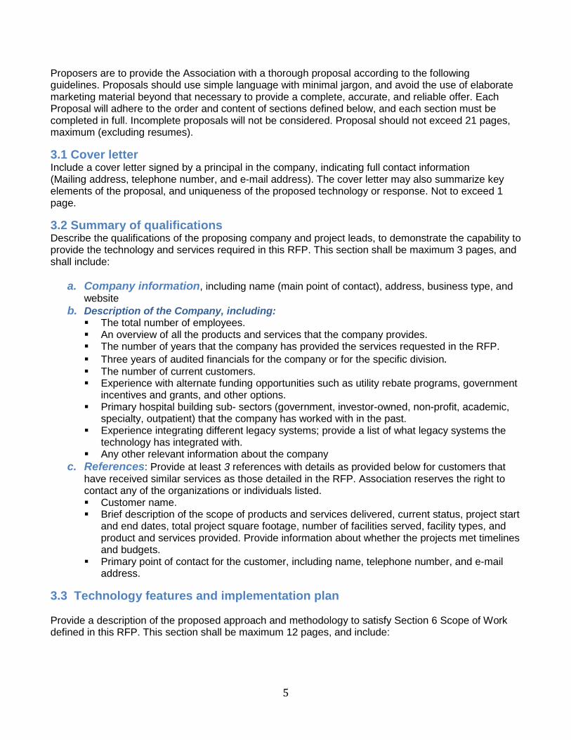
Proposers are to provide the Association with a thorough proposal according to the following guidelines. Proposals should use simple language with minimal jargon, and avoid the use of elaborate marketing material beyond that necessary to provide a complete, accurate, and reliable offer. Each Proposal will adhere to the order and content of sections defined below, and each section must be completed in full. Incomplete proposals will not be considered. Proposal should not exceed 21 pages, maximum (excluding resumes).
3.1 Cover letter Include a cover letter signed by a principal in the company, indicating full contact information (Mailing address, telephone number, and e-mail address). The cover letter may also summarize key elements of the proposal, and uniqueness of the proposed technology or response. Not to exceed 1 page.
3.2 Summary of qualifications Describe the qualifications of the proposing company and project leads, to demonstrate the capability to provide the technology and services required in this RFP. This section shall be maximum 3 pages, and shall include:
a. Company information, including name (main point of contact), address, business type, andwebsite
b. Description of the Company, including: The total number of employees. An overview of all the products and services that the company provides. The number of years that the company has provided the services requested in the RFP. Three years of audited financials for the company or for the specific division. The number of current customers. Experience with alternate funding opportunities such as utility rebate programs, government
incentives and grants, and other options. Primary hospital building sub- sectors (government, investor-owned, non-profit, academic,
specialty, outpatient) that the company has worked with in the past. Experience integrating different legacy systems; provide a list of what legacy systems the
technology has integrated with. Any other relevant information about the company
c. References: Provide at least 3 references with details as provided below for customers thathave received similar services as those detailed in the RFP. Association reserves the right tocontact any of the organizations or individuals listed. Customer name. Brief description of the scope of products and services delivered, current status, project start
and end dates, total project square footage, number of facilities served, facility types, andproduct and services provided. Provide information about whether the projects met timelinesand budgets.
Primary point of contact for the customer, including name, telephone number, and e-mailaddress.
3.3 Technology features and implementation plan
Provide a description of the proposed approach and methodology to satisfy Section 6 Scope of Work defined in this RFP. This section shall be maximum 12 pages, and include:

6
a. Network diagrams: Explanation of the basic system architecture of the proposed technologythat includes (1) EIS software platform and (2) EIS package with metering, gateway andsoftware.
b. Proposed technology: See section 6 of this RFP for details.c. Required capabilities description: A detailed description of how the proposed
technology provides the “required” capabilities listed in Scope of Work in the RFP.d. Optional capabilities description: A detailed description of how the proposed technology
provides the “optional” capabilities listed in the Scope of Work in the RFP.e. Additional capabilities: A description of any additional capabilities that may be of interest to
ASHE but are not specified as either “required” or “optional” in the Scope of Work in the RFP.f. Visualization: Where applicable, screenshots to clearly illustrate key reporting, visualization,
or analysis capabilities.g. IT integration: A description of how the proposed technology satisfies the IT requirements
listed in the Scope of Work in the RFP.h. Legacy integration: An overview of system compatibility with respect to sensing and control
technology provided by others. (See also the integration requirements in the RFP andassociated appendices.)
i. Wireless components: For any wireless components, note the number of sensors orchannels accommodated in gateway and router hardware.
j. Training and support: A description of the training and ongoing technical support andmaintenance services that will be provided.
k. A detailed project implementation plan, including all tasks and subtasks, durations,l. milestones, and deliverables. Include project management methods that will be used to ensure
that the time schedule will be met.m. Association responsibilities: A thorough description of specific responsibilities required of
Association (e.g., site access, provision of electrical and network diagrams, network access,etc.) in conducting the project.
3.4 Cost proposal
The cost proposal shall explain the pricing structure for all software, hardware, integration, data commissioning, and other services required, and separated by (1) EIS software technology platform, and (2) EIS package pilot implementations. (3) Include an estimated range of direct and indirect costs (e.g., personnel, travel, supplies, fringe benefits) associated with proposed EIS pilot implementations, assuming 2-3 types of potentially existing configurations.
The cost proposal shall be a maximum of 3 pages and include:
a. Sensing and metering hardware purchase, installation, integration, and commissioningfees for the pilot implementation. (Refer to Section Appendix C of the RFP).b. Communication hardware purchase and installation fees. (Refer to Appendix C of the RFP).c. Software set-up fees (e.g., software configuration, programming, license, training, etc.).d. Ongoing software fees (e.g., data storage and hosting, maintenance, access, technicalsupport and maintenance, etc.).e. Any specified technology or capabilities that add significantly to project costs.f. Any additional optional or bundled services or fees.

7
3.5 Staffing
Describe the team that will be assigned to the project, with each member’s areas of responsibility. Identify lead personnel and include a resume for each lead. This shall be a maximum of 1 page (excluding resume).
3.6 Protections and assurances
Describe the specific measures and protections that the responding company can provide to Association to ensure continuity of services in the event of bankruptcy, transfers of ownership, or other disruptions to business-as-usual operations. This shall be a maximum of 1 page.
8
4. Proposal Submission and EligibilityThis section describes the RFP procedures, including Association’s point of contact for respondent inquires, submission instructions, modification and withdrawal process, confidentiality, and other details.
4.1 Eligibility
Any U.S. companies with relevant experience and expertise. The company should have at least 5 similar projects completed, and have minimum 3 years of experience.
4.2 Preparation The Proposal content and format must follow the guidelines provided in Section 3, Proposal Format Guidelines, in the RFP.
4.3 Submission and due date
Proposals shall be submitted to the Association electronically at the following email address:
Paper submissions will not be accepted. Please clearly indicate the contents in the email subject line (Energy to Care Proposal). It is the responsibility of the vendor to ensure that all required documentation arrives on time and through the designated method. Any submissions received after the stated date and time, or those that do not contain the required information, will be considered incomplete and unresponsive, and will be disqualified from consideration.
Proposals are due by June 22, 2018, 5:00 pm CST. Late Proposals will not be accepted.
4.4 Inquiries
Questions about this RFP must be directed in writing, via e-mail, no later than June 11, 2018, 5:00 pm CST. The association will respond to questions by June 15, 2018. Questions shall be directed to at the following email address (no phone questions will be accepted):
Please clearly indicate the contents in the email subject line (Energy to Care RFP Questions). It is the responsibility of the vendor to ensure that all required documentation arrives on time and through the designated method. Any submissions received after the stated date and time, or those that do not contain the required information, will be considered incomplete and unresponsive, and will be disqualified from consideration.
4.5 Proposal validity
Proposals are to be valid for a minimum of 90 days to allow sufficient time for evaluation and selection, and any unforeseen delays in the review process.

9
4.6 Modification and withdrawal
Any proposal may be modified or withdrawn by written request of the Proposer, provided that the request is received prior to the submission deadline.
4.7 Right to Revise or Cancel the RFP:
Association reserves the right to revise this RFP prior to the date set for receiving proposals. Such revisions, if any, will be announced electronically with an amendment to this document. Association also reserves the right to cancel this RFP, in whole or in part, at any time prior to executing a contract for services. Issuance of this RFP creates no obligation to award a contract.
4.7 Right to reject proposals
Association reserves the right to reject any and all proposals for any reason, including if the firm takes exception to the terms and conditions of the RFP or fails to meet the terms, conditions, standards, specifications, and requirements of the RFP. Association reserves the right to reject all proposals in whole or in part where the Project Lead, Project Manager, and/or President and CEO have determined, after evaluation of the proposals, that award of the contract is not in the best interests of the Association.
10
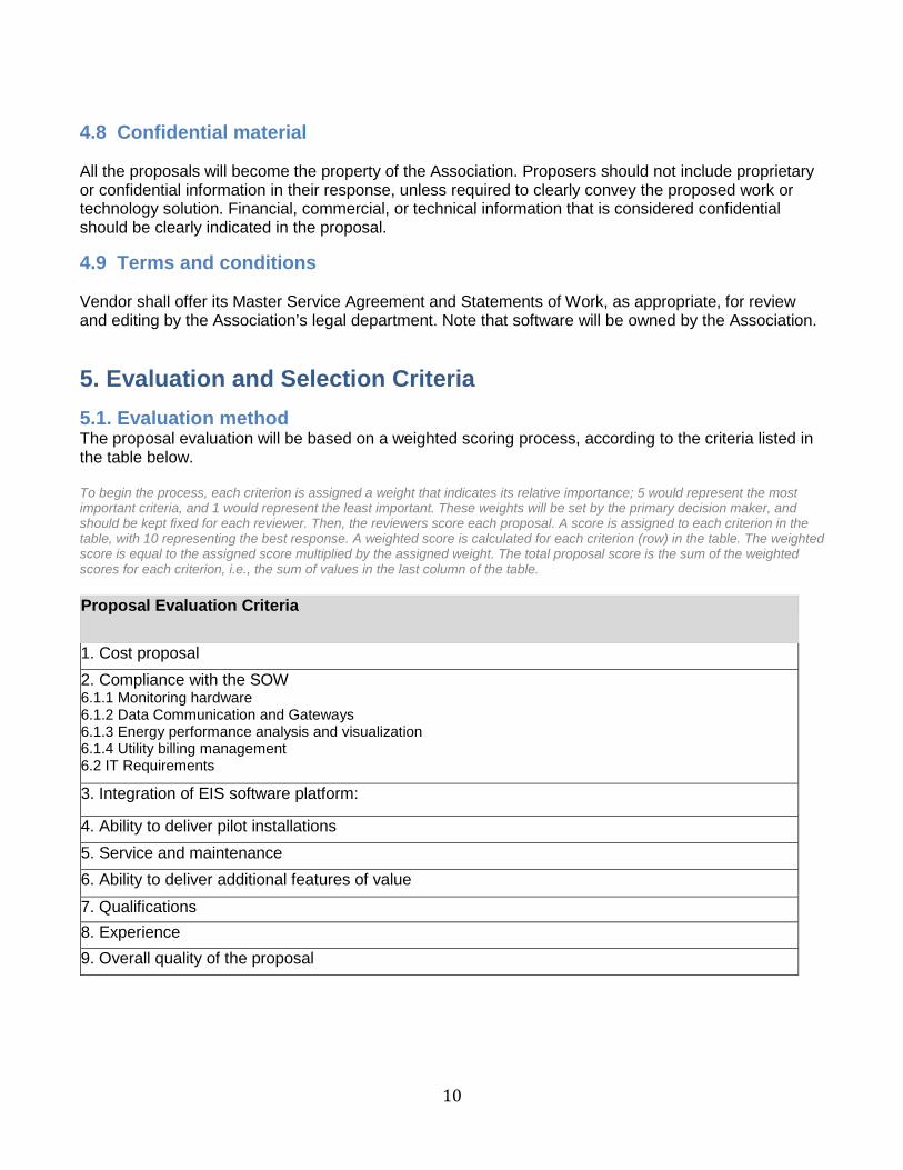
4.8 Confidential material
All the proposals will become the property of the Association. Proposers should not include proprietary or confidential information in their response, unless required to clearly convey the proposed work or technology solution. Financial, commercial, or technical information that is considered confidential should be clearly indicated in the proposal.
4.9 Terms and conditions
Vendor shall offer its Master Service Agreement and Statements of Work, as appropriate, for review and editing by the Association’s legal department. Note that software will be owned by the Association.
5. Evaluation and Selection Criteria5.1. Evaluation method The proposal evaluation will be based on a weighted scoring process, according to the criteria listed in the table below.
To begin the process, each criterion is assigned a weight that indicates its relative importance; 5 would represent the most important criteria, and 1 would represent the least important. These weights will be set by the primary decision maker, and should be kept fixed for each reviewer. Then, the reviewers score each proposal. A score is assigned to each criterion in the table, with 10 representing the best response. A weighted score is calculated for each criterion (row) in the table. The weighted score is equal to the assigned score multiplied by the assigned weight. The total proposal score is the sum of the weighted scores for each criterion, i.e., the sum of values in the last column of the table.
Proposal Evaluation Criteria
1. Cost proposal2. Compliance with the SOW6.1.1 Monitoring hardware6.1.2 Data Communication and Gateways6.1.3 Energy performance analysis and visualization6.1.4 Utility billing management6.2 IT Requirements 3. Integration of EIS software platform:
4. Ability to deliver pilot installations5. Service and maintenance6. Ability to deliver additional features of value
7. Qualifications8. Experience9. Overall quality of the proposal
11
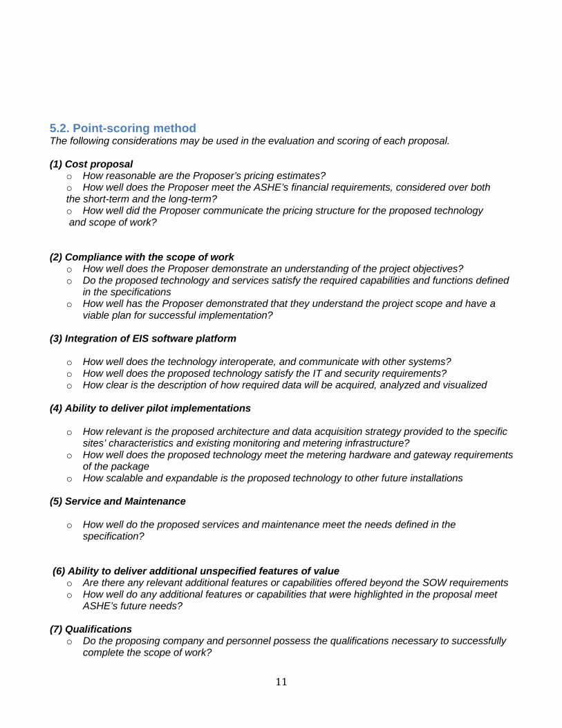
5.2. Point-scoring method The following considerations may be used in the evaluation and scoring of each proposal.
(1) Cost proposalo How reasonable are the Proposer’s pricing estimates?o How well does the Proposer meet the ASHE’s financial requirements, considered over boththe short-term and the long-term?o How well did the Proposer communicate the pricing structure for the proposed technologyand scope of work?
(2) Compliance with the scope of worko How well does the Proposer demonstrate an understanding of the project objectives?o Do the proposed technology and services satisfy the required capabilities and functions defined
in the specificationso How well has the Proposer demonstrated that they understand the project scope and have a
viable plan for successful implementation?
(3) Integration of EIS software platform
o How well does the technology interoperate, and communicate with other systems?o How well does the proposed technology satisfy the IT and security requirements?o How clear is the description of how required data will be acquired, analyzed and visualized
(4) Ability to deliver pilot implementations
o How relevant is the proposed architecture and data acquisition strategy provided to the specificsites’ characteristics and existing monitoring and metering infrastructure?
o How well does the proposed technology meet the metering hardware and gateway requirementsof the package
o How scalable and expandable is the proposed technology to other future installations
(5) Service and Maintenance
o How well do the proposed services and maintenance meet the needs defined in thespecification?
(6) Ability to deliver additional unspecified features of valueo Are there any relevant additional features or capabilities offered beyond the SOW requirementso How well do any additional features or capabilities that were highlighted in the proposal meet
ASHE’s future needs?
(7) Qualificationso Do the proposing company and personnel possess the qualifications necessary to successfully
complete the scope of work?

12
(8) Experience
o Do the proposing company and personnel possess the qualifications necessary to successfully complete the scope of work?
o Does the Proposer have a good history of experience with portfolios or sites similar to yours? o Does the Proposer demonstrate strong experience with technology design, provisioning,
installation, and commissioning? o Has the Proposer demonstrated timely and successful completion of similar projects, within
budget? o How strong are the references that the Proposer has provided?
(9) Overall quality of the proposal
o Have all the elements addressed in the Proposal Format Guidelines Part 1, Section 3 of the RFP been addressed?
o Are the protections and assurances for continuity of services, in the event of disruptions to the Proposer’s business as usual operations sufficiently addressed
o Is the writing clear and concise? o Is the proposal content well-organized and easy to follow? o Are the technical aspects of the proposal described clearly, with minimal jargon and with a
sufficient level of detail
13
6. Scope of Work
This section has a detailed description of the technology and project requirements. Please refer to the following appendixes in conjunction with this section
(1) Appendix A: Metering and Gateway Requirements provides technical requirements for thehardware selection at the pilot installations
(2) Appendix B: Visualization Charts: General Guidance provides general guidance regarding thetype of data visualization for both the EIS platform and pilot demonstrations, but is not intendedto be prescriptive.
(3) Appendix C: Informational Architecture for Data Acquisition provides an overview of variousconfigurations of how energy data may be acquired from various facilities. This is not intendedto be prescriptive.
(4) Association is currently developing a list of 3 pilot facilities. The documentation of existing sitecharacteristics, and any existing metering and monitoring infrastructure will be provided towinning vendor during the development of the solution, as Appendix D.
6.1 Technology capabilities The technology will comprise of three main components: monitoring hardware, data communication gateway and energy analysis and visualization interface, as detailed below:
6.1.1 Monitoring hardware
For the EIS Platform, the technology will integrate with existing energy meters in the member facilities - this should include utility meters for those providing monthly data and address the required wholebuilding interval meters and sub-meters for those providing real-time data, as listed under “For thepilots demonstrations” below. Data from existing meters at member facilities should be remotelyaccessed (see sub-section ‘Energy data communications and inputs’ below) and the technology shouldacquire the meter points on a monthly or sub-hourly (e.g., 15- minute) basis, based on the arrangementwith the member. See Appendix C for examples of how facilities may acquire, communicate and storedata. Provide information about your approach(es) for data acquisition, including any additionalapproaches that different from the configurations provided in Appendix C. Proposer can choose toexempt, and note any specific systems that they may exclude from integration.
For the pilot demonstrations, additional required new hardware must be provided at the pilot sites to comprehensively address the required metering points, as follows: (See Appendix A for details on each type of meter, and gateway requirements)
a. Whole-building level: Electricity, gas, oil, steam, backup powerb. Submetered level: Inpatient room cluster, chiller plant, boiler/furnace, emergency (light,
equipment, plugs), fans at distributed locations, BTU meters for cooling and heating, andradiology equipment.
c. Any renewable energy sources: Solar photovoltaic etc.
6.1.2 Data communication and gateways
6.1.2.1 Data sources
14
The technology will centralize data from various data sources as described below. The desired data sources include: (Also see Appendix A for details on each type of meter, and gateway requirements)
a. For facilities where real time data from interval meters and sub-meters is to be acquired, and forthe pilot demonstrations
o Technology must be able to integrate with and collect data in realtime, i.e 15-minuteintervals from whole building meters and submeters listed in sub-section 6.1.1.1.
o Technology must be able to support pulse output readings from meterso The technology should be able to collect interval data from remotely readable meters
using industry standard communication protocols1, with authentication and authorizationput into place. Vendors should specify the protocols supported.
b. For facilities where monthly data is to be acquired: Technology should be able to integrate withand collect data from the member’s utility bill, utility meter, or Energy Star Portfolio Manager orGreen Button account. It should push and pull data to and from the member’s Energy StarPortfolio Manager account. (optional)
c. Building data: The EIS platform should include the following data for each member facility,including pilot demonstrations:
o Building metadata: Name, location, year built, area, and year of last renovation. Customcharacteristics such as building type (government/for-profit/academic/specialty/general orspecialty outpatient/ medical office/inpatient), ownership status, campus or single facility,LEED status.
o List of metering and submetering points included
6.1.2.2 Data consolidation and storage:
a. The technology will have the capability to consolidate meter readings, to create virtual meterpoints. In other words, it can add and subtract the readings from multiple meters at the sameinterval, to produce a calculated time series of energy use.
b. The technology will be able to upload and store a minimum history of 5 years of energy use orother data from standard spreadsheet or text file format
c. The technology will have the capacity to store at least 5 years of data, trended at intervals of 15minutes for analysis, reporting, and visualization.
6.1.2.3 Integration with external data sources The technology will integrate with external data sources as follows:
a. Weather data: Technology must integrate with weather data sources such as local or on-siteweather stations, or third-party weather providers. Degree-days should be automaticallycalculated and charted for inclusion in longitudinal benchmarking analysis
b. Occupancy data: Technology must centralize occupancy data in a variety of formats, includingdesign occupancy (# patient beds for inpatient facilities; maximum designed occupancy foroutpatient facilities)
c. Utility meter data: Technology must be able to integrate with and collect data from any utilitymeter that has a pulse output option. (See Appendix C)
1 There are several possible network protocols, for e.g. BACnet, LonTalk, Modbus, DALI, C-Bus, ZigBee etc.

15
d. Utility bill data: Technology must be able to collect utility bill data from multiple sources. It mustsupport manual bill entry, bulk bill upload, and automated bill import direct from utility companiesand/or third party utility data providers. Automated bill import should be an offering for accountsat all large utility providers. (See Appendix C)
6.1.2.4 Reporting and data export Desired requirements for reports generated by the technology and data that can be exported
a. The technology must provide year-over-year, month-over- month, week-over-week and day-by-day energy, cost, or equipment health and performance reports. Reports will be generated forsingle or multiple sites in a format specified by, or acceptable to ASHE
b. The technology must provide users the ability to set thresholds for alerts and notifications(provide information whether it will be e-mail, phone, text message, etc., to individual and/orgroup recipients]
c. The technology must have the ability to create and save custom reports.d. The technology will export reports to the following file formats
.pdf .xlsx/xls .html
e. The technology will allow users to export data (all, or selected points or totalizations) to thefollowing file formats for use in external tools such as MS Excel and MS Access. .xlsx/.xls .csv .xml
6.1.2.5 Data quality checking a. The technology will provide data validation to detect quality issues such as gaps, spikes, andflat-lines, and will provide an option or service to automatically fill and/or correct data.b. The technology will provide customizable notification schemes (specifye-mail, phone, text message, etc., to individual and/or group recipients] for data quality alerting.
6.1.2.6 Energy unit conversion a. The technology will have the ability to normalize the data according to factors that are knownto affect energy consumption, such as floor area, number of beds, designed maximumoccupancy, heating degree days, and cooling degree days.b. The technology will have the capability to convert, display, and report energy use inequivalent environmental metrics such as CO2 equivalent (minimum requirement), miles drivenin a car (optional requirement), hours of laptop use (optional requirement), etc., and define anydesired conversion standards (optional requirement).
6.1.3 Energy performance analysis and visualization
The technology will analyze interval energy data and provide actionable information with the following capabilities. Appendix B provides guidance regarding data visualization but is not intended to be prescriptive.
6.1.3.1 Energy use simple tracking with baseline energy consumption modeling and alerts [see Appendix B, Chart S1 Energy Use Area chart for more information]

16
a. The technology will characterize and predict the typical or expected energy usage based onkey drivers such as weather (degree days/outside air temperature), occupancy, time ofday/week, and other variables. The baseline will be used for energy savings calculations,energy use comparisons, and energy anomaly detection. The technology will presentstatistics explaining the baseline model fitness (e.g. R2, CV-RMSE).
b. Energy anomaly detection, as variances beyond a certain percentage from the baseline.The technology will identify and flag unexpectedly high or low energy use at the buildinglevel.
c. The technology will provide the ability to track the duration, persistence of energy anomaliesto facilitate response and resolution. (optional)
d. The technology will provide notification schemes (e-mail, phone, text message, or othermessaging; individual and group recipients) for anomaly notification. The alert threshold willuser-definable.
6.1.3.2 Time series load profiling [see Appendix B, Chart S2 Power Demand Trendlines Chart for more information]
a. The technology will provide plots of at least 24-hour periods of interval energy usage versustime. It will be able to toggle the visualization between hourly, daily, weekly, monthly or annualdatab. The technology will provide options to select the time period and data points that are plotted.c. The technology will plot a typical load profile for the building type, incorporating the operatingschedule from the building automation system control sequenced. The technology will provide daily/ monthly/annual peak load monitoring.e. The technology will provide notification (e-mail/ text message) to an individual and/or groupof recipients when the demand for critical metered loads crosses a user-defined threshold.f. The technology will provide the capability to display whether a demand response event isactive or pending and to visualize and quantify demand responsive load reductions. (Optional)g. The technology will allow users to annotate charts and displays with key events, and willstore those annotations. (optional)
6.1.3.3 Longitudinal benchmarking [see Appendix B, Chart L3 Longitudinal Benchmarking Chart for more information]
a. The technology will provide the ability to compare the energy usage and costs in a fixedperiod (day/week/month/year) for a building or system against past performance of the sameperiod length.
6.1.3.4 Cross-sectional benchmarking [see Appendix B , Chart L4 Cross-sectional Benchmarking Chart more information]
a. The technology will allow the user to create “peer groups” that will contain anonymized datawith minimum view of 10 facilities, and will rank buildings by a performance index. Criticalindices are kBtu per sf, $ per year, kW per bed/occupant for inpatient facilities , or per designedoccupancy for outpatient facilities. Toggles for visualization per hour, per day or per year willprovided.b. The technology will integrate with the ENERGY STAR Portfolio Manager to automaticallyproduce ENERGY STAR scores for user-selected buildings.
6.1.3.5 Heat map visualization [see Appendix B Chart L5 Heat Map Chart for more information] a. The technology will provide heat maps of energy consumption, color-coding the magnitude ofthe metered energy usage for a user-selected time period of historic data.
17
6.1.3.6 Energy costs tracking [see Appendix B Chart L5 Heat Map Charts L2 and L3 for more information]
a. The technology will calculate and provide visualizations of real-time (and historic) fuel useand energy costs using estimated (blended) flat rates in $/energy unit or site-specific tariffs
6.1.4 Utility billing management The technology will incorporate and analyze utility billing information with capabilities as described below:
a. Billing data inputi. The technology will provide the capability to upload utility billing data (i.e., electricity,
gas, steam, water) [Specify associated file formats, such as.csv and .xlsx.]ii. The technology will provide the capability to import utility billing data directly from utility
providers [Note specific providers]iii. The technology will record all relevant utility bill details including total usage, cost,
credits/adjustments, demand charges, etc.iv. The technology will provide the capability to allocate and totalize utility costs for each
calendar month [as opposed to billing periods, which may not fall within a single month].b. The technology will provide the capability to allocate utility costs to different tenants or occupant
groups sharing a building, to enable recharges and tenant billing.
6.2. IT RequirementsVendor should seek to restrict technologies leveraged to items supported by AHA IT, these include:
• Traditional LAMP Stack Technologies (Linux, Apache, MySQL, PHP)• Amazon Web Services (AHA’s Environment/Account)• Frameworks/Libraries: Angular, React, Highcharts, JQuery, CakePHP• MarkLogic NoSQL Database• GraphQL• DrupalCMS
6.2.1 Data storage, backup, and hosting
a. Data archival will use a database (e.g., SQL, Oracle, DB2) and provide a periodic data backupoption (e.g., monthly, quarterly, yearly). The data should be accessible in a cost-effective way.
b. The technology will offer sufficient capacity to store all required data (see sub section 6.1.2.2)c. Software hosting
o For the EIS platformi. Software as a service (SaaS) operated and maintained by Association. The tool hosted by
the vendor that can be accessed from any computer (desktop or laptop) or tablet (e.g. iPad)via any web browser (Internet Explorer, Google Chrome, Firefox, Safari etc.) by allindividuals with user credentials.
ii. The solution must not require software installation on users’ computers, or installation ononsite servers
iii. Adding buildings and data in the future must be straightforward and cost effective.iv. The solution must be able to easily add additional features to their subscription without
system redesigno For the pilot demonstrationsi. On-premise maintenance will be conducted by the technology provider. Solution must includeautomatic upgrades at no additional cost to the members as they become available as part of the
18
subscription. These upgrades should happen in the background, not disrupt service, and not require any action by users.
6.2.2 Security Desired requirements for data security shall include:
a. The technology will use industry standard security protocols that comply with Association requirements for privacy and network and system protection.
b. The technology provider will indicate specific security frameworks and certifications that are utilized.
c. The technology should provide notes about what feature area supported among the following: secure socket layer (SSL) encryption, physical security, intrusion detection, security monitoring
d. The technology must include firewalls, vulnerability scans, and automated patch updates. e. The technology provider will explain their software developing life cycles (SDLC) methodology
and also indicate whether secure coding practices are followed, and how security controls are considered and built into the product.
f. The technology provider will indicate encryption capabilities for stored data.
6.2.3 Permissions, access control and backup Desired requirements for end-user access to websites, servers, and mobile applications:
a. The technology provider will indicate any limits on the number of users and/or accounts that can be accessed via web browser or mobile web applications.
b. The technology will allow user access and permissions to be constrained to specific buildings, departments, people, etc.
c. Login to the system will require a unique username and password for all users, and allow for multiple users per organization with unique logins to aid collaboration.
d. The technology provider will indicate how users have upload authentication and access control e. The technology will make provisions for a secure off-site backup
6.2.4 Usability Desired requirements for the technology user interface include:
a. The technology will condense large amounts of real-time and historical energy usage data into a graphical format that is rich, intuitive, and user friendly.
b. The technology will be accessible through multiple hardware platforms (i.e., smart phone, tablet, PCs or Macs).
c. The technology will support common browsers, including Internet Explorer, Firefox, Chrome, and Safari.
6.2.5 Networking Bandwidth requirements and communication protocol include:
a. The technology provider will indicate which protocols their technology is compatible with, including all relevant elements of the system, such as building metering and control communications, databases, web services, and Internet communications.
b. The technology provider will indicate any web browser version dependencies. c. The technology provider will specify anticipated bandwidth requirements at interfaces within the
building monitoring and control networks. d. The technology provider will address the approach to interfacing with legacy systems and
avoiding network overload
19
6.3. Technical warranty, support, and training
6.3.1 Warranty The technology provider will include a warranty that will begin after implementation, testing, and commissioning. The duration of the warranty will be at least one year from contract close-out. During the warranty period, all software and services listed will be provided to Association on a no-charge basis.
6.3.2 Technical support The duration of the technical support will be at least one year from contract close-out. Technical support will include:
6.3.2.1 The technology will provide the following help system for end users. a. A service help desk with a guaranteed response time of no more than one day
i. Vendor must provide telephone support from a dedicated support teamii. Vendor must provide easy access to support from a dedicated support team via
email.iii. Vendor must clearly define hours during which phone and email support is available
b. An online help system that includes comprehensive system documentationb. Printed documentation
6.3.2.2 The technology provider will provide a detailed list of technical support and maintenance options.
6.3.2.3 The technology provider will provide estimates of the frequency of software updates during a year and any associated system downtime.
6.3.2.4 Vendor must provide tech support structure and escalation protocols as apart of the RFP submittal.
6.3.2.5 For all hardware and software installed under this RFP for the pilot sites, provide a bound Owner’s Manual, which shall include the following:
a. Summary table detailing the makes, model #s, serial #s, installation date(s), installationlocation(s) and output data communication format/protocol.
b. Specification table, cut sheet or owner’s manual.c. Warranty information.
6.3.3 Training The technology provider will offer user training that may include the following options:
a. Tools and instructional materials in video, electronic format or hard copyb. Initial 4 hour onsite training programs at each site/campusc. Ongoing group training sessions [twice a year] to update personnel and instruct new staff
6.4. Testing and commissioning
Prior to hand-off, the technology provider will fully commission all meters, sensors, data acquisition and communications systems, and analytical functions supported by the technology for both the EIS platform and pilots. The provider will document the test and assurances that were conducted, and will make this documentation available to Association.
20
Glossary of Terms Baseline: A representation of “standard” or typical energy performance, used for comparative purposes. Baseline may be expressed according to a variety of metrics and may account for weather or other independent variables that influence energy consumption. Benchmarking: Comparing building energy performance to that of similar buildings (cross-sectional benchmarking) or its own historic performance (longitudinal benchmarking). Benchmarking may also be performed at the system or component level. Building Automation System (BAS): A system that is designed to control building operations and indoor climate. Communication Protocols: Standardized rules governing the transmission of information between devices. Common protocols for building data include, for example, BACnet, LonTalk, and Modbus. Cumulative Energy Savings: Sum of the total accrued energy savings or increases over a certain time frame, relative to the baseline. Degree Day: A measure of the heating or cooling load on a building relative to a “base” outside air temperature (e.g. 65°F). It is commonly calculated as the difference between the mean daily temperature and the “base” temperature. Demand: The rate of energy use by a particular building or system, i.e., power. Common units of energy demand are kilowatts (kW) for electricity, tons for chilled and hot water, and therms per hour or cubic feet per minute for gas. Demand Response: Changes in electric usage by customers in response to changes in the price of electricity over time or when system reliability is jeopardized. Energy Information System (EIS): Software, data acquisition hardware, and communication systems used to store, analyze, and display building energy data. Energy Management and Information System (EMIS): A broad family of tools and services to manage commercial building energy use. These technologies include, for example, energy information system, equipment-specific fault detection and diagnostic systems, benchmarking and utility tracking tools, automated system optimization tools, and building automation systems. Energy Savings: A reduction in energy use often quantified by accounting for key factors such as weather or hours of operation. Greenhouse Gas (GHG) Emissions: The carbon dioxide (CO2), methane (CH4), and nitrous oxide (N2O) gases released into the atmosphere as a result of energy consumption at the facility. Measurement and Verification (M&V): The process of using measured data and other operational information to confirm the energy savings from energy efficiency projects. The International Protocol for Measurement and Verification defines four standard M&V approaches. Peak Load: The maximum load during a specified period of time Real time data: Information that is delivered immediately after collection without delay in the timeliness of the information provided. Real-time data is often used for tracking. For the purpose of this document, the real time data should be collected and transmitted to the server every 15 minutes

Appendix A: Table of metering and gateway requirements Table 1: Metering and gateway requirements for EIS packages
Meters Submetering Points Physical Location Communication Measured
Parameters Accuracy and
Turndown
Electric meter
Whole Building electricity; Spaces or
end uses: Inpatient room cluster,
chiller plant, boiler/furnace,
emergency (light, equipment, plugs),
distributed fan locations, BTU meters
for cooling and heating, and radiology
equipment
1 Main distribution
board (DB) + representative spaces / Floor
panel
Modbus or BACnet protocol
kWh, kW, V, A, Power Factor,
For WB: current and
voltage harmonics
1% with 10:1 turndown
Gas meter
Whole Building gas; 1 major space heating
load (boiler or furnace)
1 main piping location, at all
boilers/ furnaces
Pulse output or Modbus or BACnet protocol
Submeter reads out in
cubic ft, data
required as therms
U.S. ANSI B109 standard;
1% with 100:1 turndown
Fuel oil meter Fuel oil
1 main location at each
generator unit, providing
supply and return flows
Pulse output or Modbus or BACnet protocol
Gallon 1% accuracy at 10:1 turndown
BTU meter
Cooling and heating water
At chiller and boiler plant
Pulse output or Modbus or BACnet protocol
BTU
Precision matched temperature sensors, 2% accuracy 10:1 or
4% accuracy with 100:1; Standard EN
1434
Steam vortex meter
Steam flow At boiler plant Pulse output or Modbus or BACnet protocol
lbs/hr
BTU 10:1 turn down rating or greater
The following parameters should be measured and displayed by electric submeters: i. Instantaneous phase voltage (V); phase-to-phase, phase-to-neutralii. Instantaneous phase current (A)iii. Instantaneous apparent power (VA), active power (W), and reactive power (VAR)iv. Maximum demand (W) over a specific time intervalv. Power factorvi. Frequency (Hz)vii. Active energy (kWh)

Appendix B
Visualization Charts: General GuidanceThe following visualization charts are intended to be indicative, and not prescriptive. They are mapped to RFP subsection 6.1.3
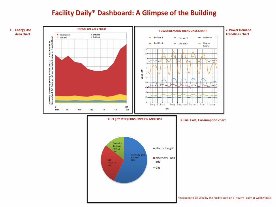
Facility Daily* Dashboard: A Glimpse of the Building
1. Energy Use Area chart
ENERGY USE AREA CHART
Time
Load
kW
End use 1
End Use 2
End use 3
End use 4
End use 5
Degree hours
2. Power Demand Trendlines chart
POWER DEMAND TRENDLINES CHART
3. Fuel Cost, Consumption chart
electricity- grid
electricity ( non-grid)
Gas
Electricity- grid400 BTUs57%
Electricity (back up)50 BTUs14%
Gas100 BTUs28%
FUEL ( BY TYPE) CONSUMPTION AND COST
*Intended to be used by the facility staff on a hourly, daily or weekly basis
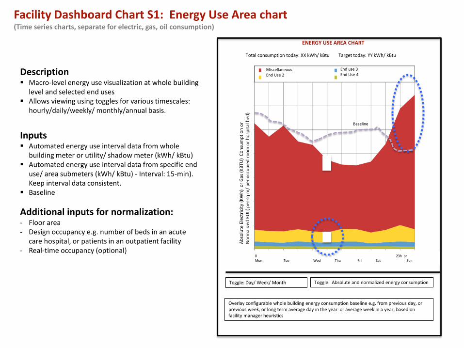
Facility Dashboard Chart S1: Energy Use Area chart(Time series charts, separate for electric, gas, oil consumption)
Description Macro-level energy use visualization at whole building
level and selected end uses Allows viewing using toggles for various timescales:
hourly/daily/weekly/ monthly/annual basis.
Inputs Automated energy use interval data from whole
building meter or utility/ shadow meter (kWh/ kBtu) Automated energy use interval data from specific end
use/ area submeters (kWh/ kBtu) - Interval: 15-min).Keep interval data consistent.
Baseline
Additional inputs for normalization: - Floor area- Design occupancy e.g. number of beds in an acute
care hospital, or patients in an outpatient facility- Real-time occupancy (optional)
Toggle: Day/ Week/ Month Toggle: Absolute and normalized energy consumption
Overlay configurable whole building energy consumption baseline e.g. from previous day, or previous week, or long term average day in the year or average week in a year; based on facility manager heuristics
Abso
lute
Ele
ctric
ity (K
Wh)
or G
as (K
BTU
) Co
nsum
ptio
n or
Nor
mal
ized
EUI (
per
sqm
/ per
occ
upie
d ro
om o
r hos
pita
l bed
)0 23h orMon Tue Wed Thu Fri Sat Sun
End use 3End Use 4
MiscellaneousEnd Use 2
Baseline
ENERGY USE AREA CHART
Total consumption today: XX kWh/ kBtu Target today: YY kWh/ kBtu
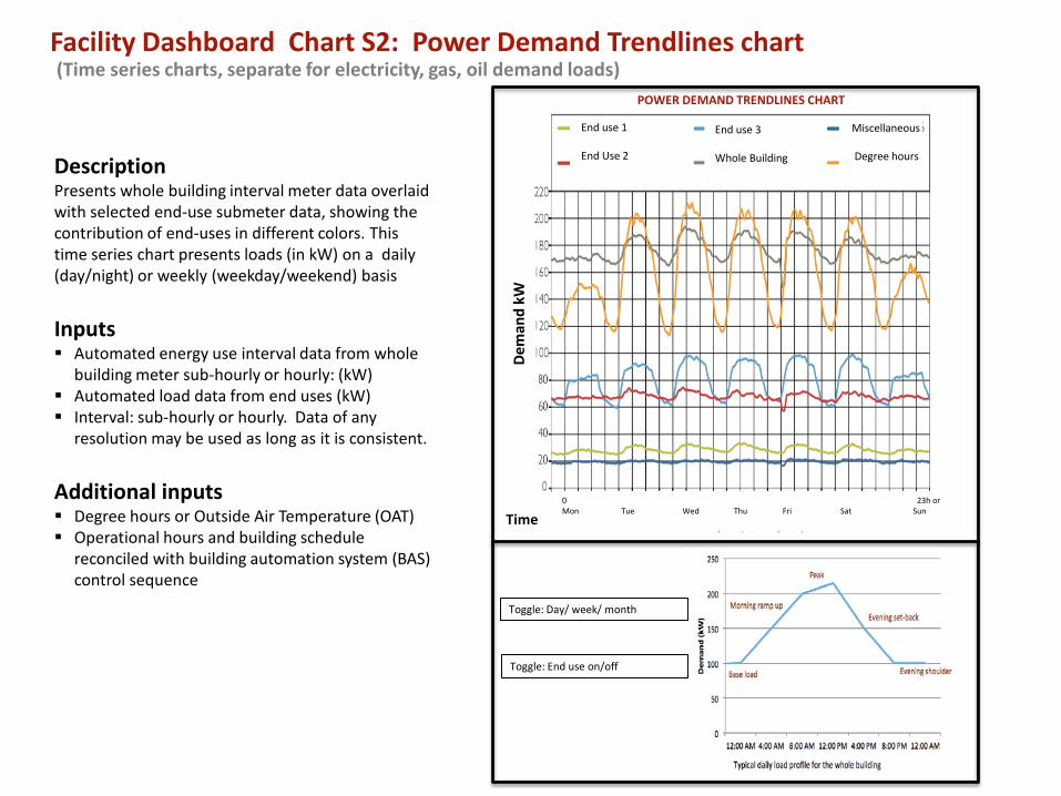
Facility Dashboard Chart S2: Power Demand Trendlines chart(Time series charts, separate for electricity, gas, oil demand loads)
DescriptionPresents whole building interval meter data overlaid with selected end-use submeter data, showing the contribution of end-uses in different colors. This time series chart presents loads (in kW) on a daily (day/night) or weekly (weekday/weekend) basis
Inputs Automated energy use interval data from whole
building meter sub-hourly or hourly: (kW) Automated load data from end uses (kW) Interval: sub-hourly or hourly. Data of any
resolution may be used as long as it is consistent.
Additional inputs Degree hours or Outside Air Temperature (OAT) Operational hours and building schedule
reconciled with building automation system (BAS)control sequence
Dem
and
kW
End use 1
End Use 2
End use 3
Whole Building
Miscellaneous
Degree hours
Time
Toggle: Day/ week/ month
Toggle: End use on/off
0 23h orMon Tue Wed Thu Fri Sat Sun
POWER DEMAND TRENDLINES CHART
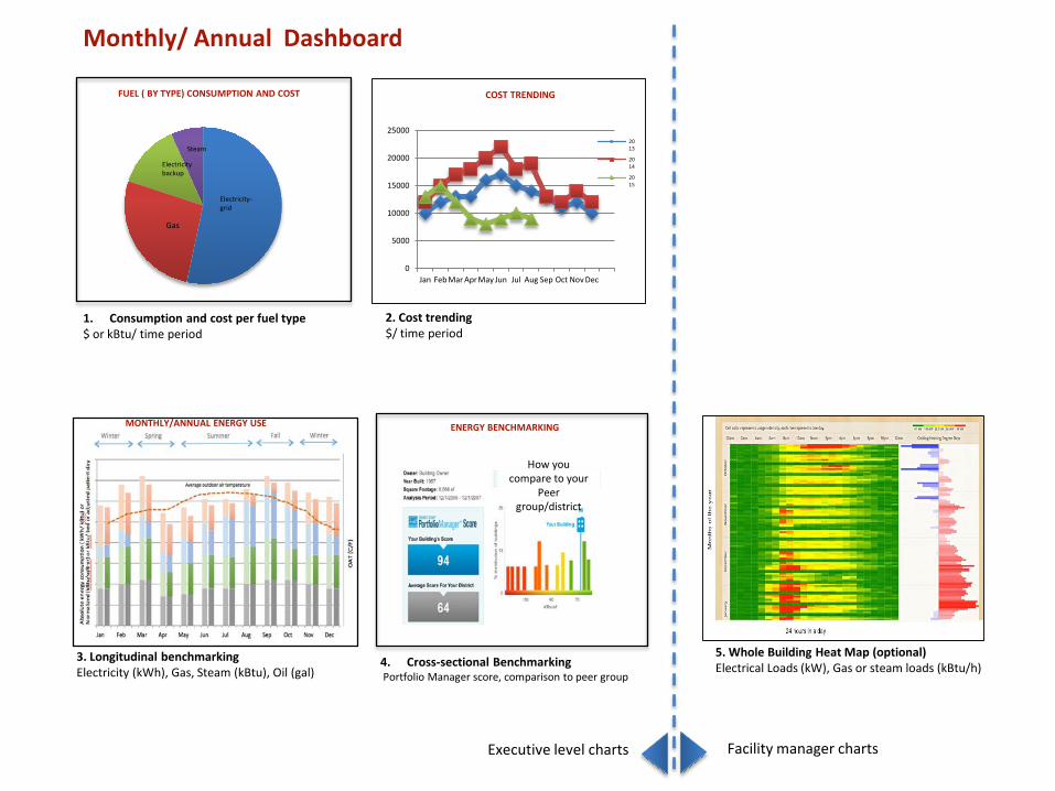
Monthly/ Annual Dashboard
5. Whole Building Heat Map (optional) Electrical Loads (kW), Gas or steam loads (kBtu/h)
Electricity-grid
Gas
FUEL ( BY TYPE) CONSUMPTION AND COST
Electricity backup
Steam
1. Consumption and cost per fuel type $ or kBtu/ time period
3. Longitudinal benchmarking Electricity (kWh), Gas, Steam (kBtu), Oil (gal)
MONTHLY/ANNUAL ENERGY USE
0
5000
10000
15000
20000
25000
Jan Feb Mar AprMay Jun Jul Aug Sep Oct Nov Dec
2013
2014
2015
2. Cost trending$/ time period
COST TRENDING
4. Cross-sectional Benchmarking Portfolio Manager score, comparison to peer group
ENERGY BENCHMARKING
Facility manager chartsExecutive level charts
How you compare to your
Peer group/district
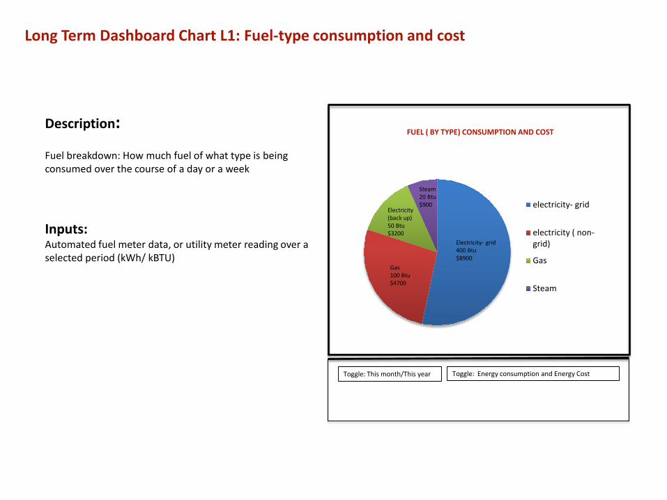
Long Term Dashboard Chart L1: Fuel-type consumption and cost
Description:
Fuel breakdown: How much fuel of what type is being consumed over the course of a day or a week
Inputs:Automated fuel meter data, or utility meter reading over a selected period (kWh/ kBTU)
Toggle: This month/This year Toggle: Energy consumption and Energy Cost
electricity- grid
electricity ( non-grid)
Gas
Steam
Electricity- grid400 Btu$8900
Gas100 Btu $4700
FUEL ( BY TYPE) CONSUMPTION AND COST
Electricity (back up)50 Btu$3200
Steam20 Btu$900
0
5000
10000
15000
20000
25000
Jan Feb Mar Apr May Jun Jul Aug Sep Oct Nov Dec
Cost trend ($/month): 2013-2015
2013
2014
2015
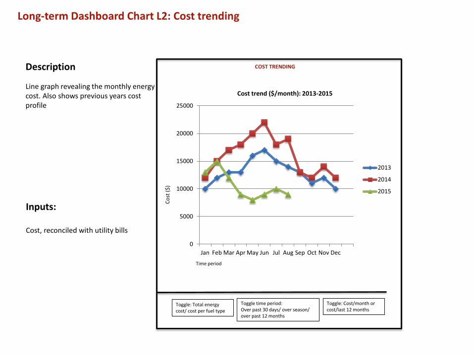
Long-term Dashboard Chart L2: Cost trending
Inputs:
Cost, reconciled with utility bills
Description
Line graph revealing the monthly energy cost. Also shows previous years cost profile
Toggle: Total energy cost/ cost per fuel type
Toggle time period: Over past 30 days/ over season/ over past 12 months
Cost
($)
Time period
COST TRENDING
Toggle: Cost/month or cost/last 12 months
0
10
20
30
40
50
60
70
80
Jan Feb Mar Apr May Jun Jul Aug Sep Oct Nov Dec
Average outdoor air temperature
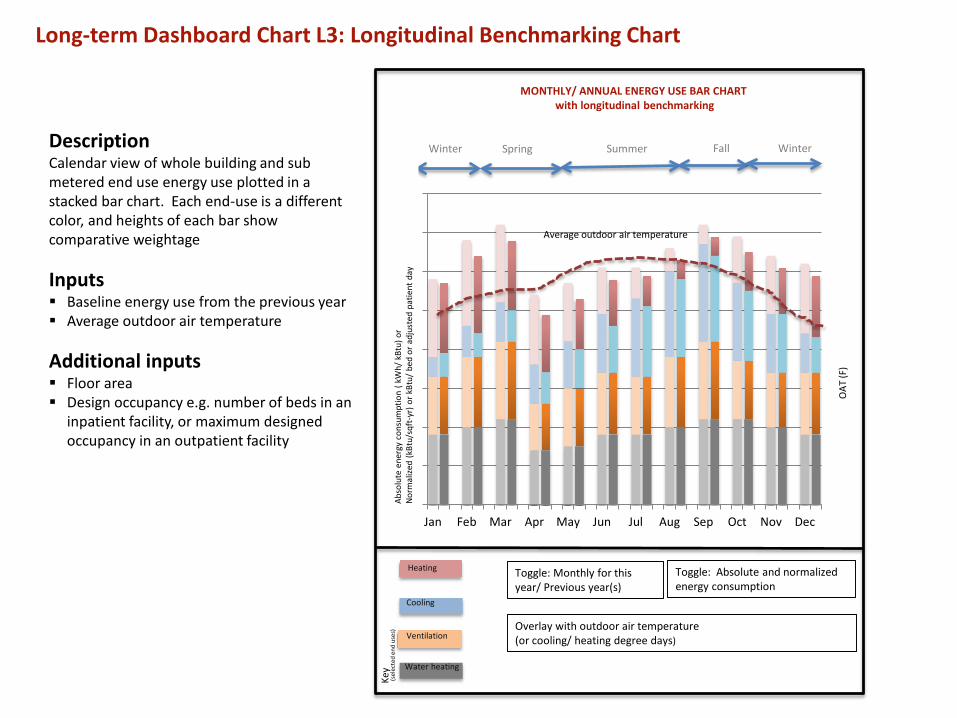
Long-term Dashboard Chart L3: Longitudinal Benchmarking Chart
DescriptionCalendar view of whole building and sub metered end use energy use plotted in a stacked bar chart. Each end-use is a different color, and heights of each bar show comparative weightage
Inputs Baseline energy use from the previous year Average outdoor air temperature
Additional inputs Floor area Design occupancy e.g. number of beds in an
inpatient facility, or maximum designedoccupancy in an outpatient facility
Toggle: Monthly for this year/ Previous year(s)
Heating
Cooling
Ventilation
Water heating
Toggle: Absolute and normalized energy consumption
Overlay with outdoor air temperature (or cooling/ heating degree days)
Winter Spring Summer Fall Winter
OAT
(F)
MONTHLY/ ANNUAL ENERGY USE BAR CHARTwith longitudinal benchmarking
Key
(sel
ecte
d en
d us
es)
Abso
lute
ene
rgy
cons
umpt
ion
( kW
h/ k
Btu)
or
Nor
mal
ized
(kBt
u/sq
ft-y
r) o
r kBt
u/ b
ed o
r adj
uste
d pa
tient
day
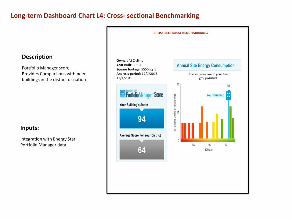
Long-term Dashboard Chart L4: Cross- sectional Benchmarking
Inputs:
Integration with Energy Star Portfolio Manager data
Description
Portfolio Manager scoreProvides Comparisons with peer buildings in the district or nation
CROSS-SECTIONAL BENCHMARKING
Owner: ABC clinicYear Built: 1987Square footage: 5555 sq ftAnalysis period: 12/1/2018-12/1/2019
How you compare to your Peer group/district
Description
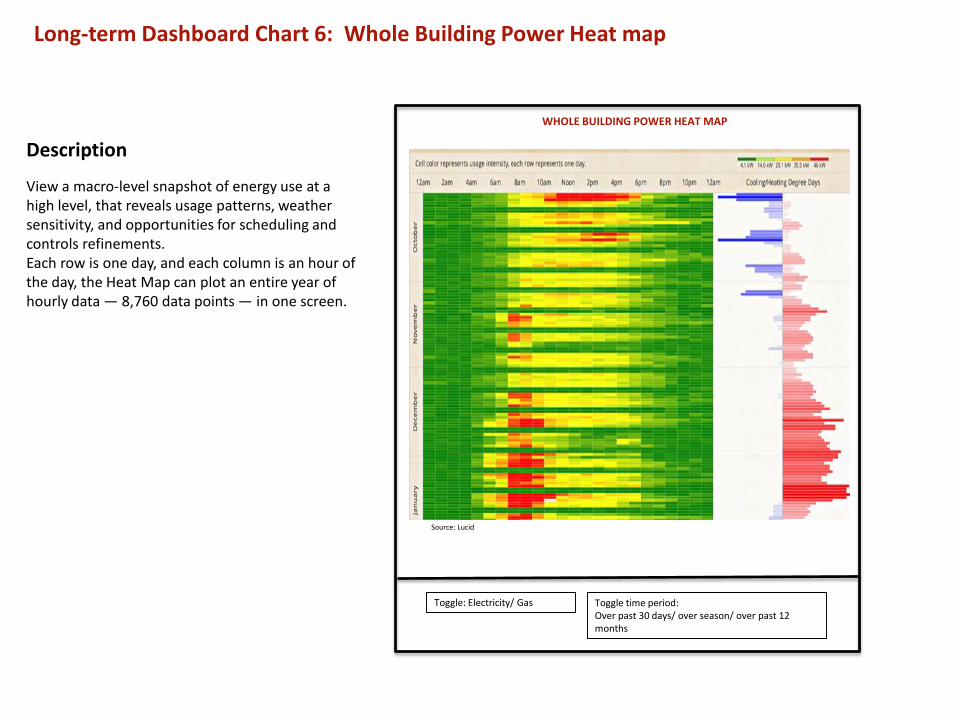
View a macro-level snapshot of energy use at a high level, that reveals usage patterns, weather sensitivity, and opportunities for scheduling and controls refinements. Each row is one day, and each column is an hour of the day, the Heat Map can plot an entire year of hourly data — 8,760 data points — in one screen.
Long-term Dashboard Chart 6: Whole Building Power Heat map
Source: Lucid
Toggle: Electricity/ Gas Toggle time period: Over past 30 days/ over season/ over past 12 months
WHOLE BUILDING POWER HEAT MAP
Appendix C
Informational Architecture for Data Acquisition
The following data acquisition architecture is intended to be indicative, and not prescriptive. They are mapped to subsection 6.1.2 of the RFP.

Data acquisition : Monthly data
Utility site meters
Additional h/w Pulse transceiver
*1
Data collector (gateway)*2
Pulse output
ASHE database/platform
Site Utility bills
ManualASHE database/platform
Utility site meters ASHE database/platformEnergy Star or
Green Button
M3
M1
M2
For facilities providing monthly energy data. M1 is manual, M2 and M3 are automated configuration options for data acquisition
Central database
*1 Wireless modbus/pulse transceiver, wirelessly transmits meter data from multiple meter points over long distances. allow systems integratorsthe ability to communicate with remote locations while avoiding the costs associated with running low voltage wiring to multiple locations in asingle or between multiple buildings. *2: Data Collector is a mechanism/device that provides connectivity to systems (HVAC, electrical etc) within abuilding. An example is a JACE box that provides the above via the Niagara framework. It connects common network protocols such as LonWorks,BACnet, and Modbus, along with proprietary networks for a unified system.
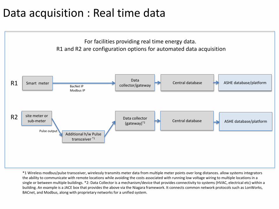
Data acquisition : Real time data
site meter or sub-meter
Additional h/w Pulse transceiver *1
Data collector (gateway)*2
Pulse output
Smart meter ASHE database/platform
*1 Wireless modbus/pulse transceiver, wirelessly transmits meter data from multiple meter points over long distances. allow systems integrators the ability to communicate with remote locations while avoiding the costs associated with running low voltage wiring to multiple locations in a single or between multiple buildings. *2: Data Collector is a mechanism/device that provides connectivity to systems (HVAC, electrical etc) within a building. An example is a JACE box that provides the above via the Niagara framework. It connects common network protocols such as LonWorks, BACnet, and Modbus, along with proprietary networks for a unified system.
Data collector/gateway
For facilities providing real time energy data. R1 and R2 are configuration options for automated data acquisition
R2
R1 BacNet IPModbus IP
Central database
Central database
ASHE database/platform

Appendix D. Pilot Sites CharacteristicsProposers can use this information in combination with the Scope of Work in Section 6 of the RFP to understand key aspects of scope, data acquisition and integration, and estimated project costs.
The Association is currently refining the pilot facilities for implementation. It is anticipated that the pilot facilities will be of the following characteristics: Large facility in central Colorado withfFault detection diagnostics, Small facility in rural central Arkansas, Mid-sized facility in central California. The following information will be provided for each pilot. Proposers can use this information in combination with the Scope of Work in Section 6 of the RFP to understand key aspects of scope, data acquisition and integration, and estimated project costs.
1) Description of the sites or campuses relevant details of lighting and HVAC equipment and design, criticalloads and services, building floor plans, etc.
2) List of existing sensors and meters that are available for integration into the monitoring, diagnostic, andanalysis technology.
a. Describe the make, model, and type of meter or sensor, what it measures (e.g., electric demand,steam flow), and the level of measurement (e.g., whole-building, system).b. Describe for each sensor and meter the associated networking and communication protocols,and where the information is stored.
3) If there is a need to integrate data from other preexisting monitoring and diagnostic systems, describethe system, and their communication and data storage protocols.
4) Provide sample historical energy consumption records if available
5) Include diagrams where possible, given information availability, and considerations of company privacyand confidentiality.