Embed Size (px)
Citation preview
ASE 1 - Engine Repair
Module 7General Engine Diagnosis
AcknowledgementsGeneral Motors, the IAGMASEP Association Board of Directors, and Raytheon ProfessionalServices, GM's training partner for GM's Service Technical College wish to thank all of thepeople who contributed to the GM ASEP/BSEP curriculum development project 2002-3. Thisproject would not have been possible without the tireless efforts of many people. Weacknowledge:
• The IAGMASEP Association members for agreeing to tackle this large project to createthe curriculum for the GM ASEP/BSEP schools.
• The IAGMASEP Curriculum team for leading the members to a single vision andimplementation.
• Direct contributors within Raytheon Professional Services for their support of translatinga good idea into reality. Specifically, we thank:
– Chris Mason and Vince Williams, for their leadership, guidance, and support.– Media and Graphics department under Mary McClain and in particular, Cheryl
Squicciarini, Diana Pajewski, Lesley McCowey, Jeremy Pawelek, & NancyDeSantis.
– For his help on the Engine Repair curriculum volume, Subject Matter Expert,Stephen Scrivner, for his wealth of knowledge.
Finally, we wish to recognize the individual instructors and staffs of the GM ASEP/BSEPColleges for their contribution for reformatting existing General Motors training material, addingcritical technical content and the sharing of their expertise in the GM product. Separatecommittees worked on each of the eight curriculum areas. For the work on this volume, wethank the members of the Engine Repair committee:
– Rick Frazier, Owens Community College– Victor Ginoba, Northern Virginia Community College– Marty Kamimoto, Fresno City College– Tony Kossman, Hudson Valley Community College– Mike Parker, New Hampshire Community Technical College– Rory Perrodin, Longview Community College
ContentsModule 7 – General Engine DiagnosisAcknowledgements .......................................................................................... 2Introduction ...................................................................................................... 5Objectives ........................................................................................................ 5
Lesson 1: Oil/Fluid Leak Diagnosis ................................................................................. 8Introduction ..................................................................................................................... 8Objective ......................................................................................................................... 8Fluid Leaks ..................................................................................................................... 8Lesson 2: Engine Mechanical Noises ........................................................................... 14Introduction ................................................................................................................... 14Objective ....................................................................................................................... 14Primary Abnormal Engine Noises ................................................................................. 14Lower Engine Noise ...................................................................................................... 16Internal Components..................................................................................................... 20Inspections for the Various Components ...................................................................... 22Lower Engine Noise ...................................................................................................... 30Internal Causes of Lower Engine Knock ....................................................................... 33Lesson 3: Base Engine Misfire Test .............................................................................. 37Introduction ................................................................................................................... 37Objective ....................................................................................................................... 37Base Engine Misfire Procedure .................................................................................... 37OBD System Check ...................................................................................................... 39DTC P0300 Engine Misfire Diagnosis Chart ................................................................. 41Misfire Counter Check (Single) ..................................................................................... 43Test Lamp J 26792 / ST 125 Spark Testing .................................................................. 44Injector Coil Test ........................................................................................................... 44Base Engine Misfire Table ............................................................................................ 45
Lesson 4: Static Compression Test ............................................................................... 46Introduction ................................................................................................................... 46Objective ....................................................................................................................... 46Static Compression Test ............................................................................................... 46Lesson 5: Running Compression Test .......................................................................... 48Introduction ................................................................................................................... 48Objective ....................................................................................................................... 48How to Perform a Running Compression Test .............................................................. 48Lesson 6: Cylinder Leakage Test .................................................................................. 50Introduction ................................................................................................................... 50Objective ....................................................................................................................... 50Cylinder Leakage Test - Testing Procedure .................................................................. 50Lesson 7: Restricted Exhaust Test ................................................................................ 53Introduction ................................................................................................................... 53Objective ....................................................................................................................... 53Restricted Exhaust Diagnostic Chart ............................................................................ 53Lesson 8: Vacuum Test ................................................................................................. 55Introduction ................................................................................................................... 55Objective ....................................................................................................................... 55Vacuum Test Diagnosis Chart ....................................................................................... 57Lesson 9: Oil Pressure Test .......................................................................................... 58Introduction ................................................................................................................... 58Objective ....................................................................................................................... 58Engine Oil Functions ..................................................................................................... 58Lesson 10: Engine Speed-Related Vibrations .............................................................. 62Introduction ................................................................................................................... 62Objective ....................................................................................................................... 62Isolating Vibrations........................................................................................................ 62Exercise 7-1 .................................................................................................................. 66
© 2002 General Motors CorporationAll Rights Reserved
ASE 1 - EngineRepair
Module 7 - GeneralEngine Diagnosis
7-5
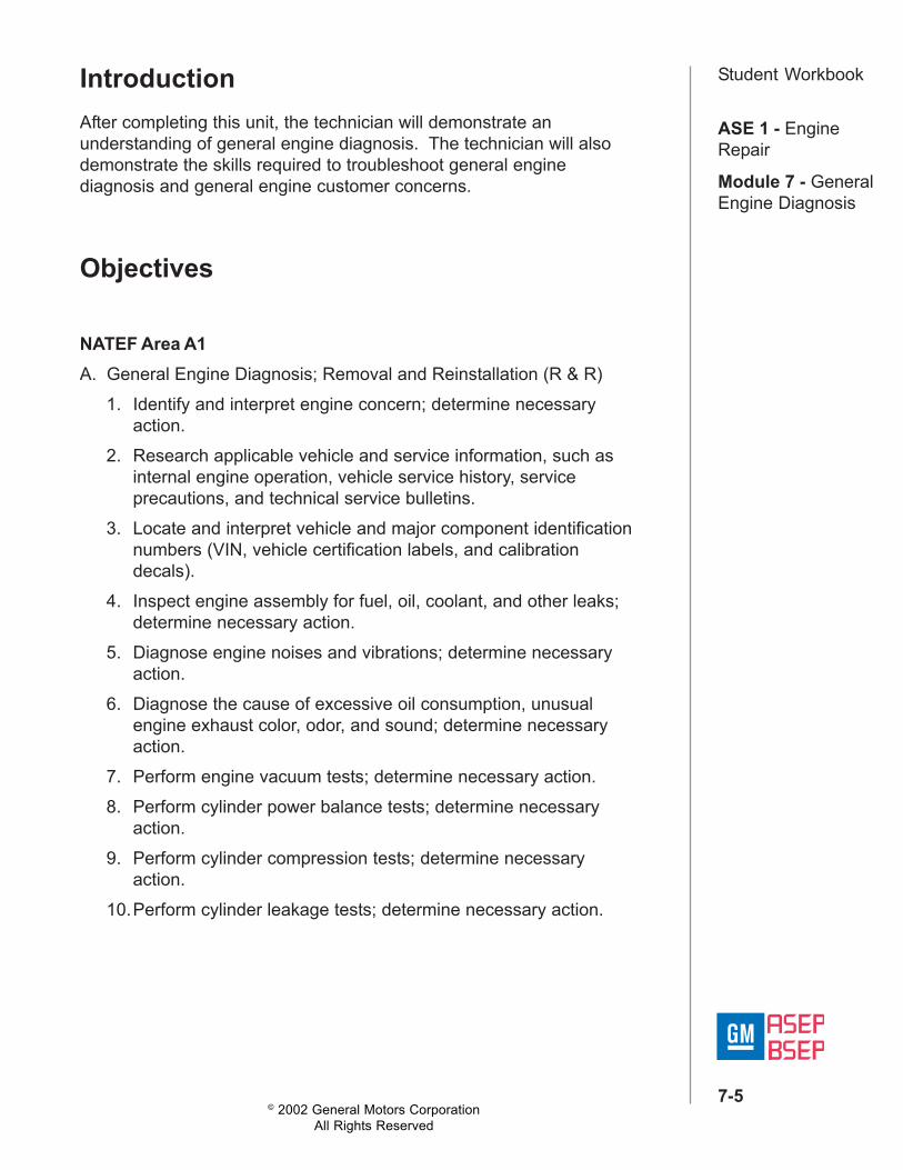
Student WorkbookIntroductionAfter completing this unit, the technician will demonstrate anunderstanding of general engine diagnosis. The technician will alsodemonstrate the skills required to troubleshoot general enginediagnosis and general engine customer concerns.
Objectives
NATEF Area A1A. General Engine Diagnosis; Removal and Reinstallation (R & R)
1. Identify and interpret engine concern; determine necessaryaction.
2. Research applicable vehicle and service information, such asinternal engine operation, vehicle service history, serviceprecautions, and technical service bulletins.
3. Locate and interpret vehicle and major component identificationnumbers (VIN, vehicle certification labels, and calibrationdecals).
4. Inspect engine assembly for fuel, oil, coolant, and other leaks;determine necessary action.
5. Diagnose engine noises and vibrations; determine necessaryaction.
6. Diagnose the cause of excessive oil consumption, unusualengine exhaust color, odor, and sound; determine necessaryaction.
7. Perform engine vacuum tests; determine necessary action.8. Perform cylinder power balance tests; determine necessary
action.9. Perform cylinder compression tests; determine necessary
action.10.Perform cylinder leakage tests; determine necessary action.
© 2002 General Motors CorporationAll Rights Reserved
ASE 1 - EngineRepair
Module 7 - GeneralEngine Diagnosis
7-6
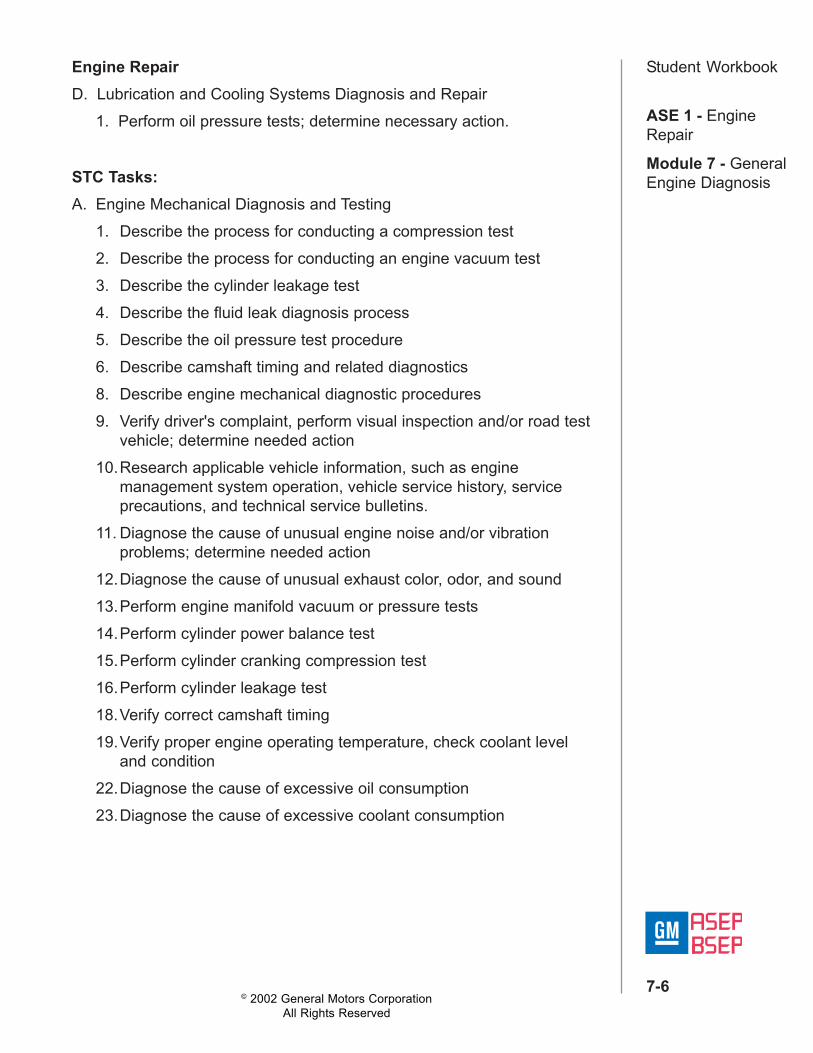
Student WorkbookEngine RepairD. Lubrication and Cooling Systems Diagnosis and Repair
1. Perform oil pressure tests; determine necessary action.
STC Tasks:A. Engine Mechanical Diagnosis and Testing
1. Describe the process for conducting a compression test2. Describe the process for conducting an engine vacuum test3. Describe the cylinder leakage test4. Describe the fluid leak diagnosis process5. Describe the oil pressure test procedure6. Describe camshaft timing and related diagnostics8. Describe engine mechanical diagnostic procedures9. Verify driver's complaint, perform visual inspection and/or road test
vehicle; determine needed action10.Research applicable vehicle information, such as engine
management system operation, vehicle service history, serviceprecautions, and technical service bulletins.
11. Diagnose the cause of unusual engine noise and/or vibrationproblems; determine needed action
12.Diagnose the cause of unusual exhaust color, odor, and sound13.Perform engine manifold vacuum or pressure tests14.Perform cylinder power balance test15.Perform cylinder cranking compression test16.Perform cylinder leakage test18.Verify correct camshaft timing19.Verify proper engine operating temperature, check coolant level
and condition22.Diagnose the cause of excessive oil consumption23.Diagnose the cause of excessive coolant consumption
© 2002 General Motors CorporationAll Rights Reserved
ASE 1 - EngineRepair
Module 7 - GeneralEngine Diagnosis
7-7
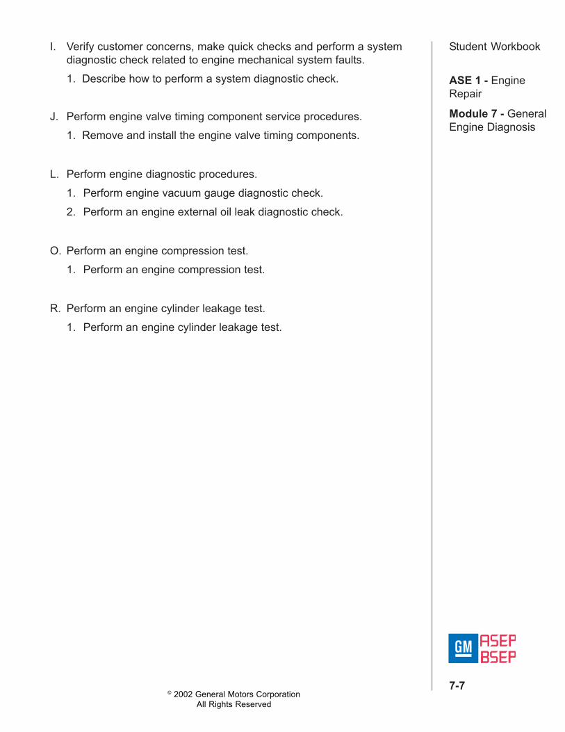
Student WorkbookI. Verify customer concerns, make quick checks and perform a systemdiagnostic check related to engine mechanical system faults.1. Describe how to perform a system diagnostic check.
J. Perform engine valve timing component service procedures.1. Remove and install the engine valve timing components.
L. Perform engine diagnostic procedures.1. Perform engine vacuum gauge diagnostic check.2. Perform an engine external oil leak diagnostic check.
O. Perform an engine compression test.1. Perform an engine compression test.
R. Perform an engine cylinder leakage test.1. Perform an engine cylinder leakage test.
© 2002 General Motors CorporationAll Rights Reserved
ASE 1 - EngineRepair
Module 7 - GeneralEngine Diagnosis
7-8
Student WorkbookLesson 1: Oil/Fluid Leak DiagnosisIntroductionAfter completing this unit, the technician will demonstrate anunderstanding of oil leak diagnosis. The technician will also demonstratethe skills required to troubleshoot oil leak diagnosis and address customerconcerns.
ObjectiveDescribe the procedures to check for oil leaks and identify possiblesources of oil leaks.
Notice:It is important to correctly identify the source of an oil leak. A powersteering fluid leak or spillage can travel across the valley area of theengine and run out the weep hole, which is located at the back of theblock. Failure to correctly identify the source of an oil leak can lead to theincorrect or unnecessary replacement of components.
Fluid LeaksAlthough oil is one of the main fluids in the engine compartment, there areseveral other types of fluid that can be mistaken for an oil leak. Manytimes as fluid migrates through the engine compartment, it will pick updebris and may not be easy to identify.
Engine Compartment Fluids• Coolant• Power steering fluid• A/C PAG oil• Transmission fluid• Front axle lube• Electrolyte
© 2002 General Motors CorporationAll Rights Reserved
ASE 1 - EngineRepair
Module 7 - GeneralEngine Diagnosis
7-9
Student WorkbookAny of these fluids can migrate from the leak point and travel down theengine. You can repair most fluid leaks by first visually locating the leak,repairing or replacing the component, or by resealing the gasket surface.Once the leak is identified, determine the cause of the leak. Repair thecause of the leak as well as the leak itself.To determine if the leaking fluid is engine oil, transmission fluid, powersteering fluid, brake fluid, or some other fluid, use the visual inspectionmethod.
Visual Inspection Method1. Bring the vehicle to normal operating temperature.2. Park the vehicle over a large sheet of paper, or other clean surface.3. Wait several minutes, and then check for drippings.4. Identify the type of fluid, and the approximate location of the leak. 5. Visually inspect the suspected area. Use a small mirror to assist in
looking at hard to see areas. 6. Check for leaks at sealing surfaces, fittings, or from cracked or
damaged components. 7. If you cannot locate the leak, do the following:
a. Completely clean the entire engine and surrounding components.b. Operate the vehicle for several miles at normal operation
temperature and at varying speeds.c. Park the vehicle over a large sheet of paper, or other clean surface.d. Wait several minutes, and then check for drippings.e. Identify the type of fluid, and the approximate location of the leak.f. Visually inspect the suspected area. Use a small mirror to assist in
looking at hard to see areas.g. See possible causes for leaks.
If you still cannot locate the leak, use the powder method or the black lightand dye method.
© 2002 General Motors CorporationAll Rights Reserved
ASE 1 - EngineRepair
Module 7 - GeneralEngine Diagnosis
7-10
Student WorkbookPowder Method1. Completely clean the entire engine and surrounding components.2. Apply an aerosol-type powder (baby powder, foot powder, etc.) to the
suspected area.3. Operate the vehicle for several miles at normal operation temperature
and at varying speeds.4. Identify the type of fluid, and the approximate location of the leak, from
the discolorations in the powder surface. 5. Visually inspect the suspected area. Use a small mirror to assist in
looking at hard to see areas. 6. See possible causes for leaks.
To identify the source of the leak, it's often necessary to use leak dye toidentify the leak point and thus the type of fluid.
Black Light and Dye Method1. A dye and light kit is available for finding leaks. Use the J 28428-E
or equivalent. Refer to the manufacturer's instructions when usingthe tool.
2. Visually inspect the suspected area. Use a small mirror to assist inlooking at hard to see areas.
3. See possible causes for leaks.
© 2002 General Motors CorporationAll Rights Reserved
ASE 1 - EngineRepair
Module 7 - GeneralEngine Diagnosis
7-11
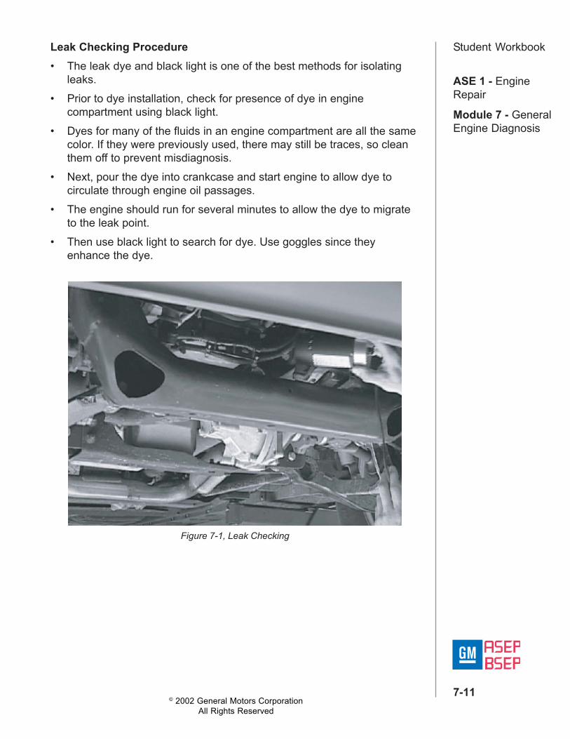
Student WorkbookLeak Checking Procedure• The leak dye and black light is one of the best methods for isolating
leaks.• Prior to dye installation, check for presence of dye in engine
compartment using black light.• Dyes for many of the fluids in an engine compartment are all the same
color. If they were previously used, there may still be traces, so cleanthem off to prevent misdiagnosis.
• Next, pour the dye into crankcase and start engine to allow dye tocirculate through engine oil passages.
• The engine should run for several minutes to allow the dye to migrateto the leak point.
• Then use black light to search for dye. Use goggles since theyenhance the dye.
Figure 7-1, Leak Checking
© 2002 General Motors CorporationAll Rights Reserved
ASE 1 - EngineRepair
Module 7 - GeneralEngine Diagnosis
7-12
Student WorkbookNotice:Remember, small leaks may require additional time to become visible.Leak may only occur as the engine cools down.
Important:Do not get dye on the vehicle finish since it can damage the paint.
Possible Causes for LeaksCheck for the following conditions:• Higher than recommended fluid levels• Higher than recommended fluid pressures• Plugged or malfunctioning fluid filters or pressure bypass valves• Plugged or malfunctioning engine ventilation system• Improperly tightened or damaged fasteners• Cracked or porous components• Improper sealants or gaskets where required• Improper sealant or gasket installation• Damaged or worn gaskets or seals• Damaged or worn sealing surfaces
© 2002 General Motors CorporationAll Rights Reserved
ASE 1 - EngineRepair
Module 7 - GeneralEngine Diagnosis
7-13
Student WorkbookLoss of Coolant1. Check for an incorrect or faulty surge tank cap.2. Ensure that the cooling system is full.3. Pressure test the cooling system.4. While the cooling system is pressurized, inspect for any external
coolant leaks.5. Repair or replace the leaking component(s) as necessary.6. Check the heater core for leakage7. Start the engine and inspect.8. Check for excessive white smoke from the exhaust and/or rough
engine idle.9. Road test the vehicle and allow the engine to reach full operating
temperature.10.Make sure the engine does not overheat.11. Remove the oil level indicator stick and inspect.
Important:Ensure that the cause of the creamy or milky substance is not caused byshort drive cycles or a faulty thermostat. Either of these conditions willcause creamy or milky deposits to form in the engine oil because theengine cannot reach full operating temperature in order to dissipate thecondensation/moisture.
12.Make sure the engine reached full operating temperature during all ofthe vehicle drive cycles. The probable cause of the coolant loss is anengine internal coolant leak. If the spark plug electrodes or theporcelain surrounding the spark plug electrodes exhibit signs ofcoolant, replace the applicable cylinder head(s) or cylinder headgasket(s).
13.Ensure that the cooling system is full. (Refer to Draining and FillingCooling System).
14.Operate the system in order to verify the repair.
© 2002 General Motors CorporationAll Rights Reserved
ASE 1 - EngineRepair
Module 7 - GeneralEngine Diagnosis
7-14
Student WorkbookLesson 2: Engine Mechanical NoisesIntroductionAfter completing this unit, the technician will be able to apply concepts andprocedures to diagnose engine mechanical concerns.
Objective• Identify the primary types of engine mechanical noise.• Explain what engine noises sound like.• Explain how engine noise can be affected by load.• Identify the type of engine faults that can cause the various engine
noises.• Explain how engine noise can cause a misfire DTC.There are four steps to diagnosing engine noise. You must determine thefollowing conditions:• Type of noise.• Determine the exact operating condition under which the noise exists.• At what rate, and at what location in the engine.• Compare sounds in other engines to make sure you are not trying to
correct a normal condition.
Primary Abnormal Engine NoisesThere are two broad categories that the service information uses toclassify noise.• Upper engine or valve train noise: generally associated with tick.• Lower engine noise: generally associated with knockIn order to make the best use of the service information you must be ableto classify an engine noise in one of these two categories.
© 2002 General Motors CorporationAll Rights Reserved
ASE 1 - EngineRepair
Module 7 - GeneralEngine Diagnosis
7-15
Student WorkbookUpper Engine (Valve Train) NoiseValve train noise is generally associated with a ticking noise. Although notall valve train noises make the same type of ticking noise, their occurrencewill be related to the speed of the camshaft.Valve train noise is related to engine speed:• The camshaft drives valve train components.• The camshaft rotates at half the speed of the crankshaft; therefore,
valve train noises will be at 1/2 engine speed.• Engine speed is based on the crankshaft speed.• For example, if the engine speed is 600 RPM, the cam speed will be
300 RPM. The valve train noise will occur 5 times per second.
General Sources of Valve Train Noise• Camshaft(s)• Lifters/Stationary Hydraulic Lash Adjusters (SHLA)• Pushrods• Rocker arms• Valve components• Guides• Carbon build up on valves• Timing chain• Balance shaft
Noises related to these items will increase in frequency as the engineRPM increases. For example, as the engine RPM increases they willoccur more often, but still at half engine RPM.
© 2002 General Motors CorporationAll Rights Reserved
ASE 1 - EngineRepair
Module 7 - GeneralEngine Diagnosis
7-16
Student WorkbookLower Engine NoiseGeneral SourcesLower engine noise is generally associated with a knocking noise, andoccurs once per engine revolution. At 600 RPM, a lower engine noise willoccur 10 times per second.Lower Engine Knocking Sources• Piston slap• Main/rod bearing knock• Piston pin knock• Flywheel (loose or broken)• Carbon in the combustion chamberNoises related to these items will increase in frequency as the engineRPM increases, and are directly related to engine RPM. However, someknock noises will be more pronounced when the cylinder is underpressure during the compression and power strokes. Engine noises canchange with engine load or temperature.
How Load Affects Engine Noises• Engine load can change the intensity of the noise.• The noise may only occur or be more noticeable under a heavy load• For example, a bearing with excessive clearance may not create a
noise at idle, but will knock when in gear.
How Temperature Affects Engine Noises• Some noises may only occur when the engine is either cold or at
operating temperature.• Some clearance-related noises will decrease in intensity when the
engine warms-up and the engine components expand, taking up theclearance.
• Lubrication concerns may only appear when the engine is at operatingtemperature.
• Carbon in the cylinder will generally only cause noise when the engineis cold and it goes away when the engine warms-up.
© 2002 General Motors CorporationAll Rights Reserved
ASE 1 - EngineRepair
Module 7 - GeneralEngine Diagnosis
7-17
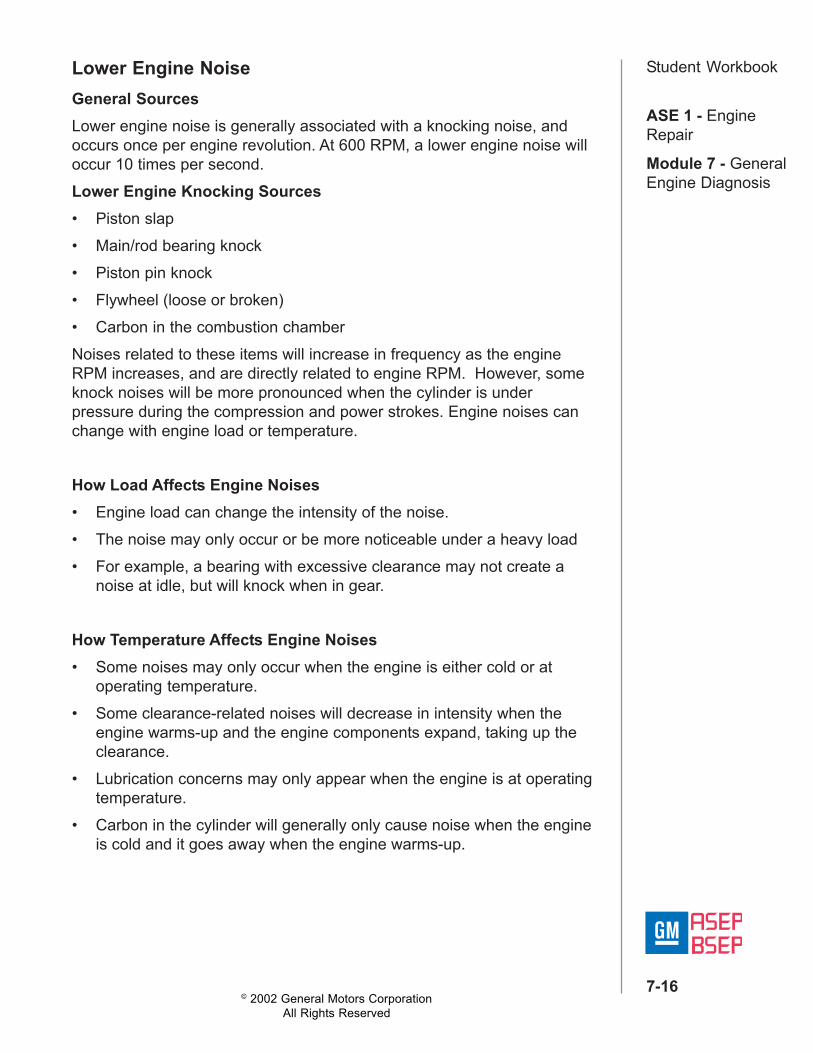
Student WorkbookTop Engine Cleaner
• Used to clean carbon deposits from internal engine components.Does not require engine disassembly.
• Start the engine and allow it to reach operating temp.• With engine idling, disconnect PCV hose from PCV valve and slowly
spray top engine cleaner into hose.• Raise engine speed to approx. 2000 rpm and when white smoke is
coming out of exhaust, shut off engine.• Let cleaner work for at least 20 minutes.• Start engine and increase speed to 2000 RPM until exhaust is no
longer white. This will remove the cleaner.• Remember to change oil; cleaner could contaminate it.• If the noise was result of carbon, this should remove it. If the noise is
still present, perform additional diagnostics.
Figure 7-2, Top Engine Cleaner
Notice:There has been a lot of concern about carbon build-up recently and thereare bulletins related to this topic. Make sure you check for bulletins beforeperforming service. Most times, the bulletins have procedures that werecreated as a result of working and testing on vehicles with the concern.
Upper Engine FaultsAs with any diagnosis, do the easiest things first. Here are examples ofsome external engine faults that could create what may sound like anupper engine noise.The first area is accessories. They can create a variety of noises, but ifthere is an engine noise, take a few minutes to make sure it's not relatedto the accessories.
© 2002 General Motors CorporationAll Rights Reserved
ASE 1 - EngineRepair
Module 7 - GeneralEngine Diagnosis
7-18
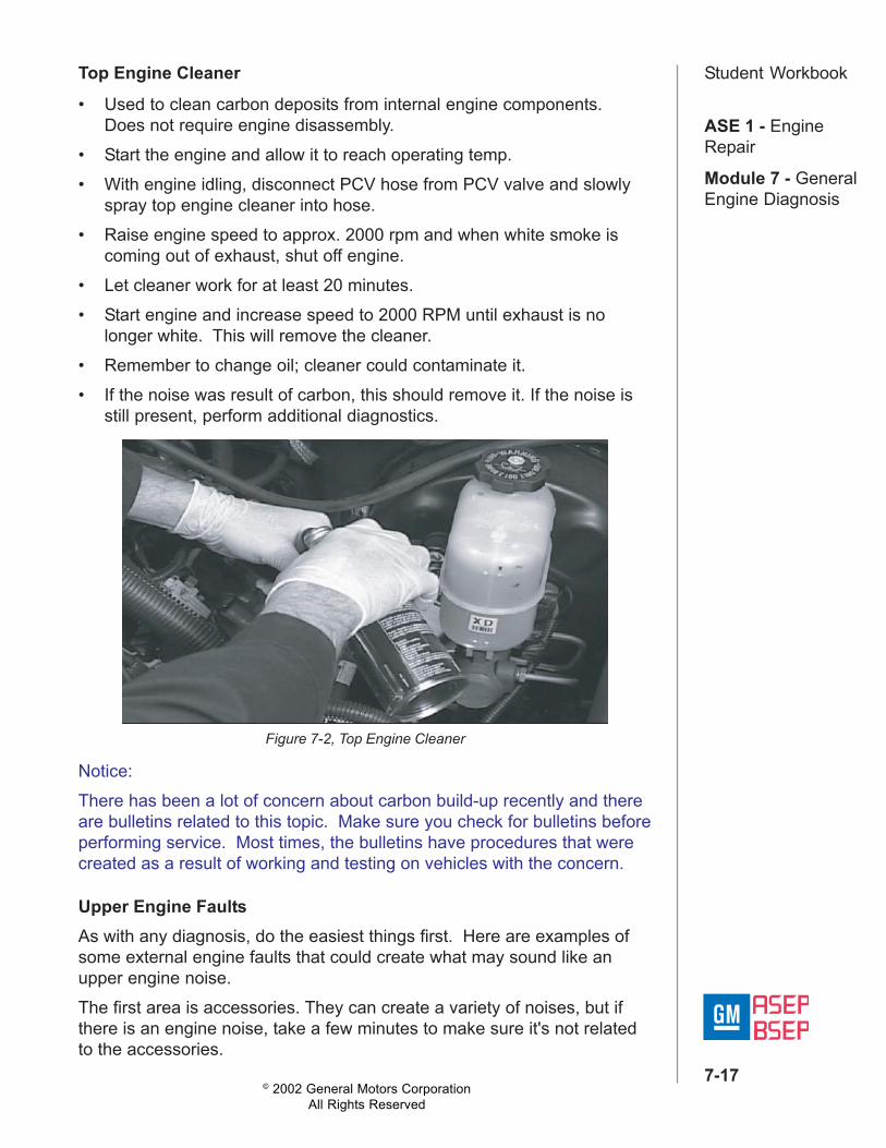
Student WorkbookAccessories
Figure 7-3, Accessory Drive Belt
© 2002 General Motors CorporationAll Rights Reserved
ASE 1 - EngineRepair
Module 7 - GeneralEngine Diagnosis
7-19
Student Workbook
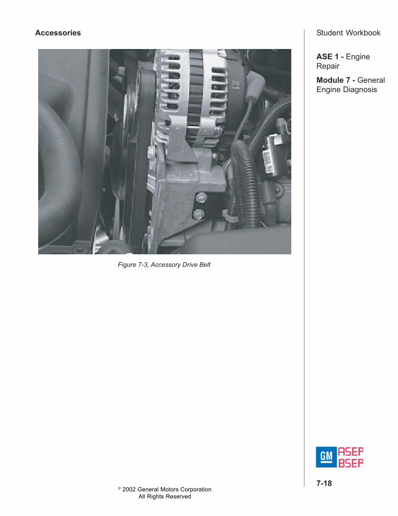
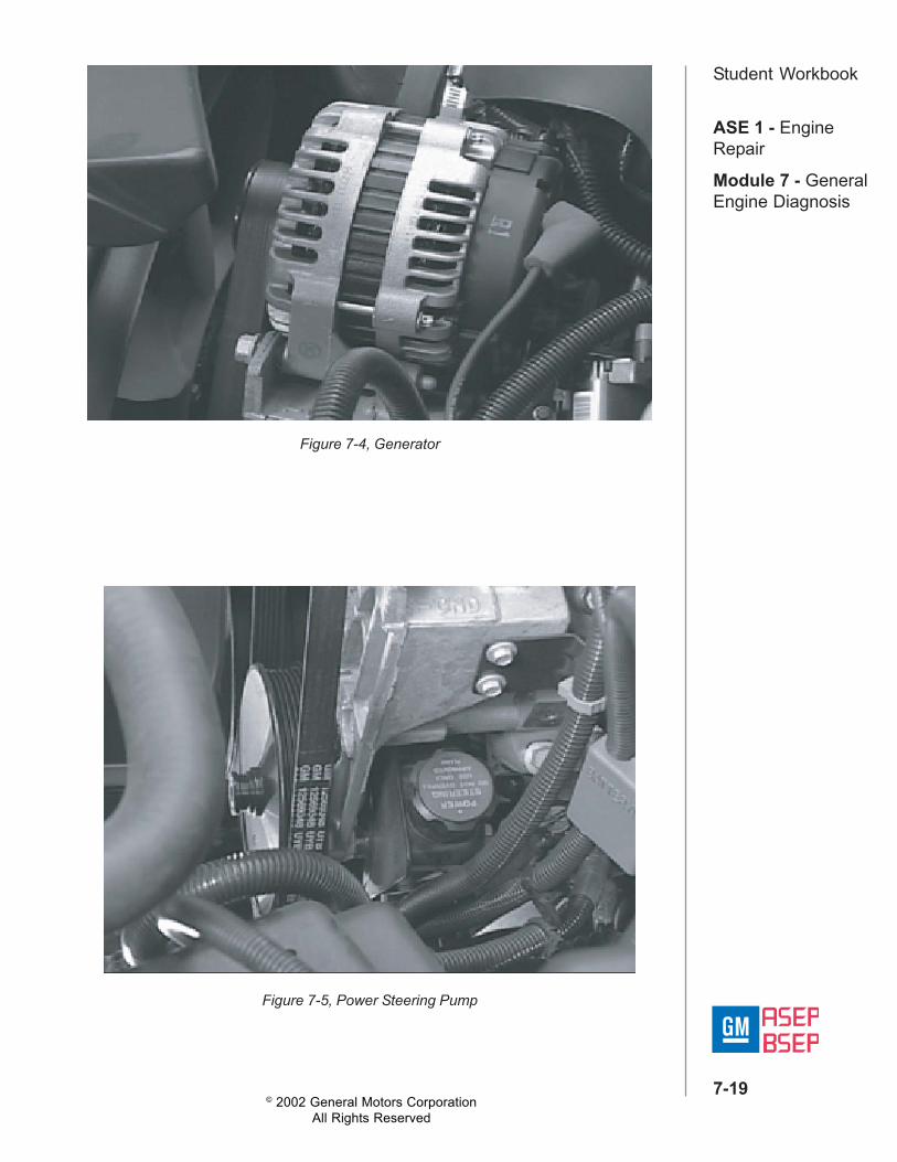
Figure 7-4, Generator
Figure 7-5, Power Steering Pump
© 2002 General Motors CorporationAll Rights Reserved
ASE 1 - EngineRepair
Module 7 - GeneralEngine Diagnosis
7-20
Student WorkbookIn addition to the accessory system there are several other areas thatshould be checked that are external to the engine.Loose spark plug:• Changing pressure inside the cylinder pushes and pulls the spark
plug against the threads of the cylinder head.• This causes a metal-to-metal clicking noise.• A loose spark plug may be caused by damaged threads, requiring
thread repair.• Remember, spark plug threads in aluminum cylinder heads are
frequently damaged when removing them with the engine hot.
Exhaust leak:• Unmuffled exhaust pulses can escape through leaks.• This can cause a ticking noise.
Internal ComponentsPrimary Areas for Upper Engine Noises• Upper valve train• Timing chainsThe upper valve train is any component that is being driven by thecamshaft or camshafts. To help isolate the source of the noise, usechassis ears or a stethoscope.
© 2002 General Motors CorporationAll Rights Reserved
ASE 1 - EngineRepair
Module 7 - GeneralEngine Diagnosis
7-21
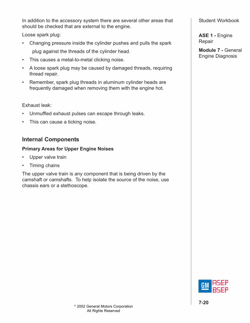
Student WorkbookValve Train Noise Isolation• Use the wooden handle of a hammer and place it on the rocker arms.• Requires engine to run with valve covers removed. So, make sure oil
does not drip on any hot surfaces, and keep body parts and clothingaway from moving components.
• Using the wooden handle against the rocker arms removes theclearance in the valve train. If there is noise caused by excessiveclearance it should go away when placing tension on rocker arm.
• You'll have to do this to each rocker arm to determine which valve traincomponent is creating the noise.
• Check both sides of rocker arm. First take the clearance out of valveside then out of the camshaft side.
• If valve train noise goes away or is reduced when handle is placed onvalve side, check valve clearance, rocker arm and valve componentsfor damage.
• If noise reduces or goes away when the handle is placed on camshaftside, check rocker arm, pushrod, lifter and camshaft for damage.
Figure 7-6, Valve Train Noise Isolation
© 2002 General Motors CorporationAll Rights Reserved
ASE 1 - EngineRepair
Module 7 - GeneralEngine Diagnosis
7-22
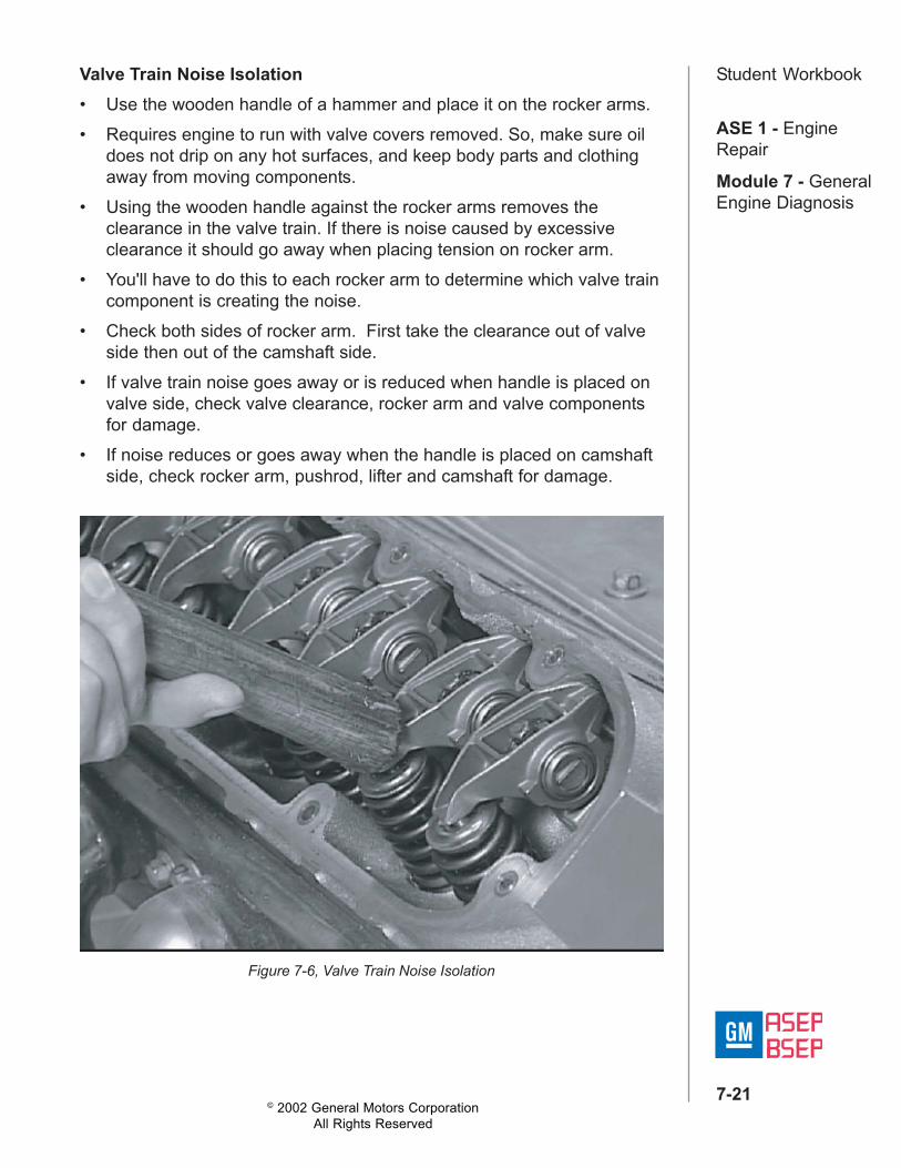
Student WorkbookInspections for the Various ComponentsChecking Valve Clearance• Start by checking the valve clearance:
– If there is excessive clearance, determine what is causing it. Thismay include checking the camshaft lobes.
– If the clearance is OK, start checking for indications of insufficientlubrication.
– If the lubrication isn't the cause, check for carbon on the valves andfor valve damage.
– If the valve clearance is incorrect, inspect for several things,starting with the easier checks.
Figure 7-7, Checking Valve Clearance
© 2002 General Motors CorporationAll Rights Reserved
ASE 1 - EngineRepair
Module 7 - GeneralEngine Diagnosis
7-23
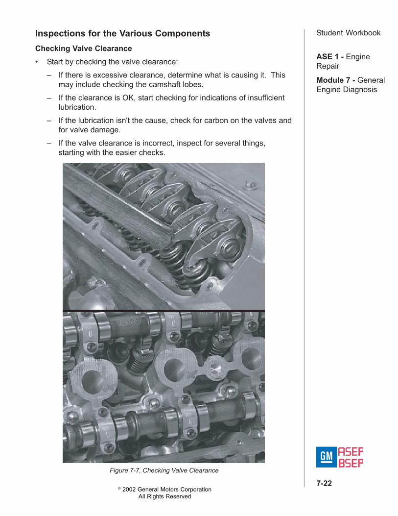
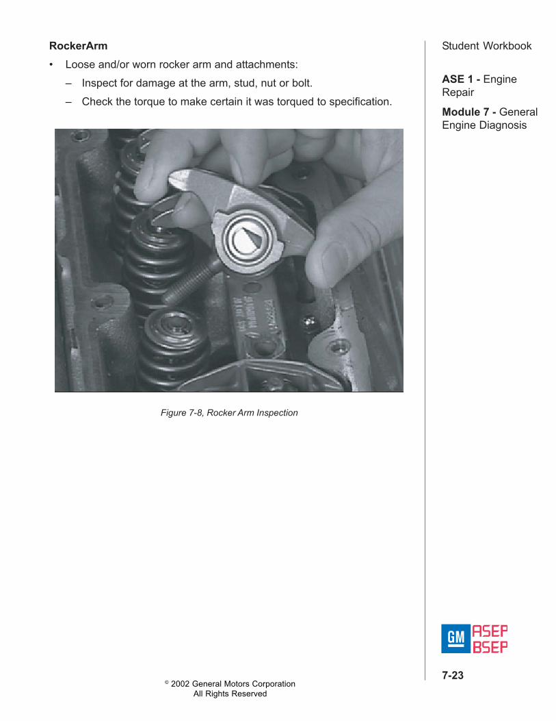
Student WorkbookRockerArm• Loose and/or worn rocker arm and attachments:
– Inspect for damage at the arm, stud, nut or bolt.– Check the torque to make certain it was torqued to specification.
Figure 7-8, Rocker Arm Inspection
© 2002 General Motors CorporationAll Rights Reserved
ASE 1 - EngineRepair
Module 7 - GeneralEngine Diagnosis
7-24
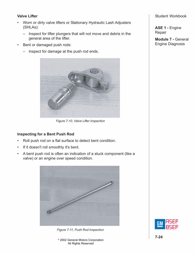
Student WorkbookValve Lifter• Worn or dirty valve lifters or Stationary Hydraulic Lash Adjusters
(SHLAs):– Inspect for lifter plungers that will not move and debris in the
general area of the lifter.• Bent or damaged push rods:
– Inspect for damage at the push rod ends.
Figure 7-10, Valve Lifter Inspection
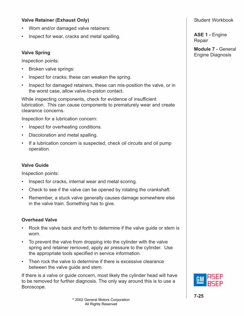
Inspecting for a Bent Push Rod• Roll push rod on a flat surface to detect bent condition.• If it doesn't roll smoothly it's bent.• A bent push rod is often an indication of a stuck component (like a
valve) or an engine over speed condition.
Figure 7-11, Push Rod Inspection
© 2002 General Motors CorporationAll Rights Reserved
ASE 1 - EngineRepair
Module 7 - GeneralEngine Diagnosis
7-25
Student WorkbookValve Retainer (Exhaust Only)• Worn and/or damaged valve retainers:• Inspect for wear, cracks and metal spalling.
Valve SpringInspection points:• Broken valve springs:• Inspect for cracks; these can weaken the spring.• Inspect for damaged retainers, these can mis-position the valve, or in
the worst case, allow valve-to-piston contact.While inspecting components, check for evidence of insufficientlubrication. This can cause components to prematurely wear and createclearance concerns.Inspection for a lubrication concern:• Inspect for overheating conditions.• Discoloration and metal spalling.• If a lubrication concern is suspected, check oil circuits and oil pump
operation.
Valve GuideInspection points:• Inspect for cracks, internal wear and metal scoring.• Check to see if the valve can be opened by rotating the crankshaft.• Remember, a stuck valve generally causes damage somewhere else
in the valve train. Something has to give.
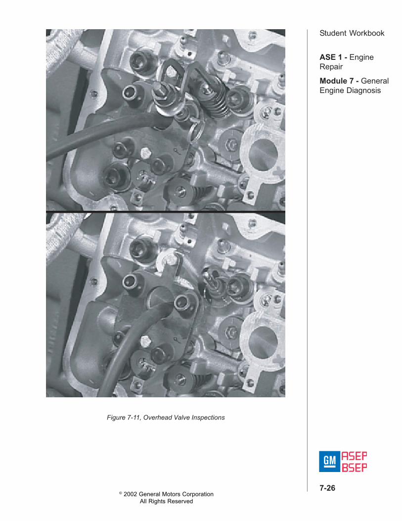
Overhead Valve• Rock the valve back and forth to determine if the valve guide or stem is
worn.• To prevent the valve from dropping into the cylinder with the valve
spring and retainer removed, apply air pressure to the cylinder. Usethe appropriate tools specified in service information.
• Then rock the valve to determine if there is excessive clearancebetween the valve guide and stem.
If there is a valve or guide concern, most likely the cylinder head will haveto be removed for further diagnosis. The only way around this is to use aBoroscope.
© 2002 General Motors CorporationAll Rights Reserved
ASE 1 - EngineRepair
Module 7 - GeneralEngine Diagnosis
7-26
Student Workbook
Figure 7-11, Overhead Valve Inspections
© 2002 General Motors CorporationAll Rights Reserved
ASE 1 - EngineRepair
Module 7 - GeneralEngine Diagnosis
7-27
Student WorkbookValveInspection points:• Worn valve stems:
– Inspect for cracks, breaks, overheating, pitting and metal spalling.– Bent (roll the stem on a flat surface).
• Carbon on the valve can also cause noise.– Remember, carbon related noise generally goes away when the
engine heats up.– If you suspect carbon, use the top engine cleaner before
disassembling the engine.
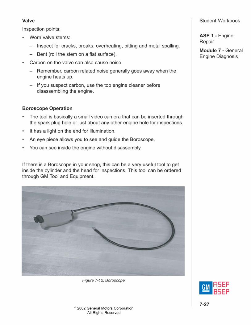
Boroscope Operation• The tool is basically a small video camera that can be inserted through
the spark plug hole or just about any other engine hole for inspections.• It has a light on the end for illumination.• An eye piece allows you to see and guide the Boroscope.• You can see inside the engine without disassembly.
If there is a Boroscope in your shop, this can be a very useful tool to getinside the cylinder and the head for inspections. This tool can be orderedthrough GM Tool and Equipment.
Figure 7-12, Boroscope
© 2002 General Motors CorporationAll Rights Reserved
ASE 1 - EngineRepair
Module 7 - GeneralEngine Diagnosis
7-28
Student WorkbookDetonation• Detonation can also cause an upper engine ticking noise.• It can cause or be caused by mechanical faults.• OBD II has been designed to detect misfire conditions like detonation.• Some detonation concerns could be caused by fuel.
CamshaftsA worn or damaged camshaft can cause excessive clearance in the valvetrain. There are procedures in the service information called "Camshaftand Bearings Cleaning and Inspection" which will lead you through thechecks for the camshaft.Types of inspections:• Check lobes for wear and signs of lube starvation.• Increased clearance between the camshaft lobes and lifters can create
a clicking noise as camshaft turns.• Also check bearings and retainers.
Balance ShaftThe balance shaft can cause a detonation/rattle noise that is mostnoticeable under a slight load.Inspection points:• Damaged bearings, broken balance shaft or worn balance shaft
sprocket teeth.
© 2002 General Motors CorporationAll Rights Reserved
ASE 1 - EngineRepair
Module 7 - GeneralEngine Diagnosis
7-29
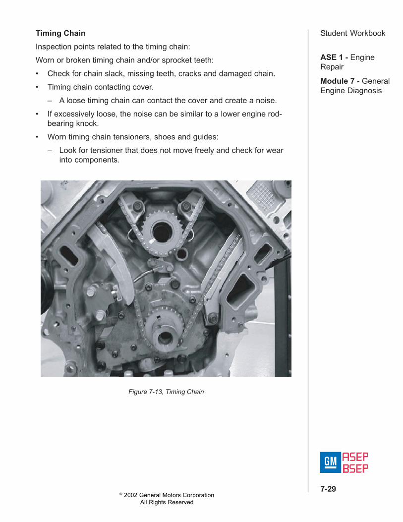
Student WorkbookTiming ChainInspection points related to the timing chain:Worn or broken timing chain and/or sprocket teeth:• Check for chain slack, missing teeth, cracks and damaged chain.• Timing chain contacting cover.
– A loose timing chain can contact the cover and create a noise.• If excessively loose, the noise can be similar to a lower engine rod-
bearing knock.• Worn timing chain tensioners, shoes and guides:
– Look for tensioner that does not move freely and check for wearinto components.
Figure 7-13, Timing Chain
© 2002 General Motors CorporationAll Rights Reserved
ASE 1 - EngineRepair
Module 7 - GeneralEngine Diagnosis
7-30
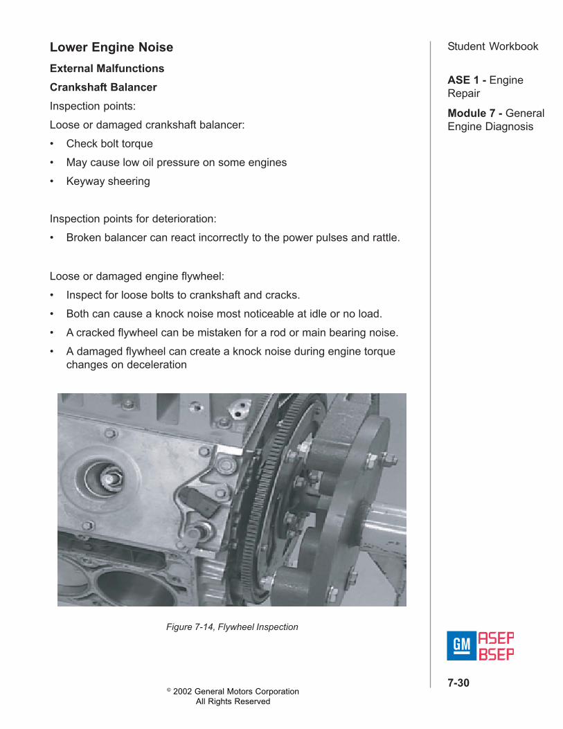
Student WorkbookLower Engine NoiseExternal MalfunctionsCrankshaft BalancerInspection points:Loose or damaged crankshaft balancer:• Check bolt torque• May cause low oil pressure on some engines• Keyway sheering
Inspection points for deterioration:• Broken balancer can react incorrectly to the power pulses and rattle.
Loose or damaged engine flywheel:• Inspect for loose bolts to crankshaft and cracks.• Both can cause a knock noise most noticeable at idle or no load.• A cracked flywheel can be mistaken for a rod or main bearing noise.• A damaged flywheel can create a knock noise during engine torque
changes on deceleration
Figure 7-14, Flywheel Inspection
© 2002 General Motors CorporationAll Rights Reserved
ASE 1 - EngineRepair
Module 7 - GeneralEngine Diagnosis
7-31
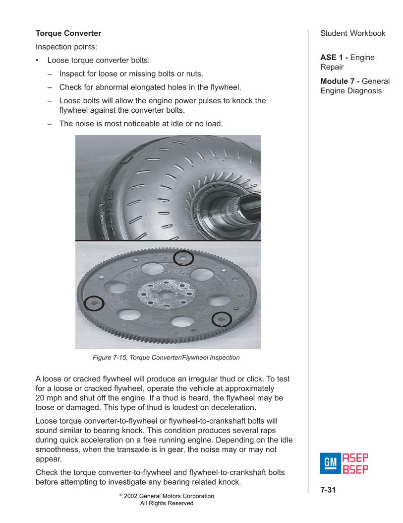
Student WorkbookTorque ConverterInspection points:• Loose torque converter bolts:
– Inspect for loose or missing bolts or nuts.– Check for abnormal elongated holes in the flywheel.– Loose bolts will allow the engine power pulses to knock the
flywheel against the converter bolts.– The noise is most noticeable at idle or no load.
Figure 7-15, Torque Converter/Flywheel Inspection
A loose or cracked flywheel will produce an irregular thud or click. To testfor a loose or cracked flywheel, operate the vehicle at approximately20 mph and shut off the engine. If a thud is heard, the flywheel may beloose or damaged. This type of thud is loudest on deceleration.Loose torque converter-to-flywheel or flywheel-to-crankshaft bolts willsound similar to bearing knock. This condition produces several rapsduring quick acceleration on a free running engine. Depending on the idlesmoothness, when the transaxle is in gear, the noise may or may notappear.Check the torque converter-to-flywheel and flywheel-to-crankshaft boltsbefore attempting to investigate any bearing related knock.
© 2002 General Motors CorporationAll Rights Reserved
ASE 1 - EngineRepair
Module 7 - GeneralEngine Diagnosis
7-32
Student WorkbookNotice:Be sure the converter-to-flywheel bolts are not too long. Converter boltsthat are too long may dimple the torque converter clutch apply surfacecausing a shudder condition.
Pan DamageAlso check the oil pan for external damage. If the pan is damaged, thiscould indicate other concerns inside the pan, which could restrictlubrication.Pan Damage Can Cause:• Pan contact with the suction screen.• Pickup tube damage.• Oil pump damage.• Engine block damage.Also check the oil filter. Some aftermarket filters do not have the correctspecifications and can restrict flow and allow drain back.
Detonation and FuelFuel can be related to engine noises:• Wrong grade or contaminated fuel can cause detonation and knock
noises.• Higher octane than needed has also caused carbon concerns since
the high-octane fuel is designed to burn slower.• The benefit of high octane is that it reduces ping in high compression
engines.• However, if the engine is generally operated for only short trips and is
not allowed to reach operating temperature, the slow burning fuel cancause carbon build up.
• Since the engine is not given an opportunity to burn off the carbon, itbuilds up to a point where it can cause noise and must be removed.
© 2002 General Motors CorporationAll Rights Reserved
ASE 1 - EngineRepair
Module 7 - GeneralEngine Diagnosis
7-33
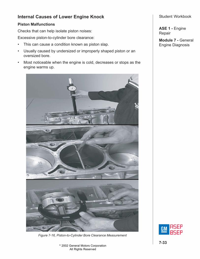
Student WorkbookInternal Causes of Lower Engine KnockPiston MalfunctionsChecks that can help isolate piston noises:Excessive piston-to-cylinder bore clearance:• This can cause a condition known as piston slap.• Usually caused by undersized or improperly shaped piston or an
oversized bore.• Most noticeable when the engine is cold, decreases or stops as the
engine warms up.
Figure 7-16, Piston-to-Cylinder Bore Clearance Measurement
© 2002 General Motors CorporationAll Rights Reserved
ASE 1 - EngineRepair
Module 7 - GeneralEngine Diagnosis
7-34
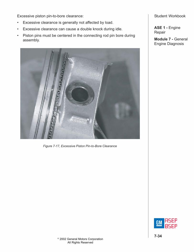
Student WorkbookExcessive piston pin-to-bore clearance:• Excessive clearance is generally not affected by load.• Excessive clearance can cause a double knock during idle.• Piston pins must be centered in the connecting rod pin bore during
assembly.
Figure 7-17, Excessive Piston Pin-to-Bore Clearance
© 2002 General Motors CorporationAll Rights Reserved
ASE 1 - EngineRepair
Module 7 - GeneralEngine Diagnosis
7-35
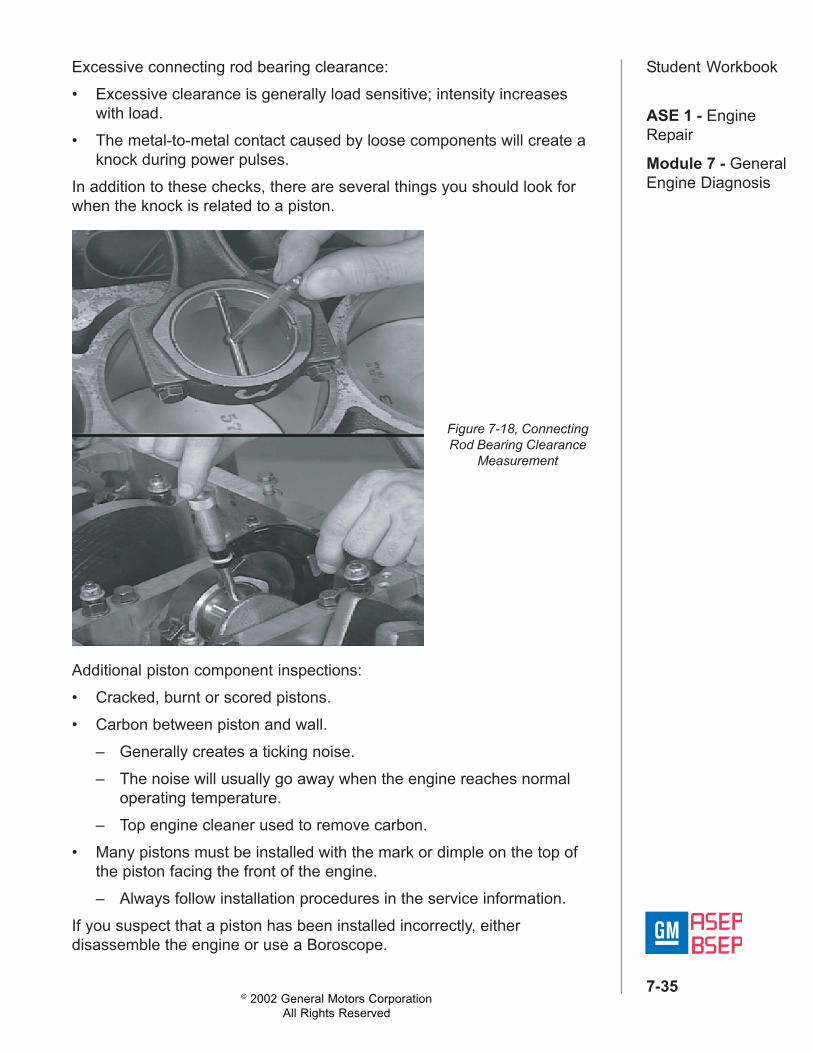
Student WorkbookExcessive connecting rod bearing clearance:• Excessive clearance is generally load sensitive; intensity increases
with load.• The metal-to-metal contact caused by loose components will create a
knock during power pulses.In addition to these checks, there are several things you should look forwhen the knock is related to a piston.
Figure 7-18, ConnectingRod Bearing Clearance
Measurement
Additional piston component inspections:• Cracked, burnt or scored pistons.• Carbon between piston and wall.
– Generally creates a ticking noise.– The noise will usually go away when the engine reaches normal
operating temperature.– Top engine cleaner used to remove carbon.
• Many pistons must be installed with the mark or dimple on the top ofthe piston facing the front of the engine.– Always follow installation procedures in the service information.
If you suspect that a piston has been installed incorrectly, eitherdisassemble the engine or use a Boroscope.
© 2002 General Motors CorporationAll Rights Reserved
ASE 1 - EngineRepair
Module 7 - GeneralEngine Diagnosis
7-36
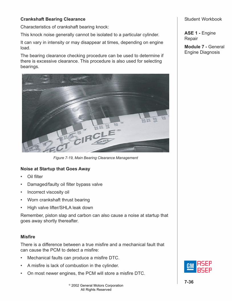
Student WorkbookCrankshaft Bearing ClearanceCharacteristics of crankshaft bearing knock:This knock noise generally cannot be isolated to a particular cylinder.It can vary in intensity or may disappear at times, depending on engineload.The bearing clearance checking procedure can be used to determine ifthere is excessive clearance. This procedure is also used for selectingbearings.
Figure 7-19, Main Bearing Clearance Management
Noise at Startup that Goes Away• Oil filter• Damaged/faulty oil filter bypass valve• Incorrect viscosity oil• Worn crankshaft thrust bearing• High valve lifter/SHLA leak downRemember, piston slap and carbon can also cause a noise at startup thatgoes away shortly thereafter.
MisfireThere is a difference between a true misfire and a mechanical fault thatcan cause the PCM to detect a misfire:• Mechanical faults can produce a misfire DTC.• A misfire is lack of combustion in the cylinder.• On most newer engines, the PCM will store a misfire DTC.
© 2002 General Motors CorporationAll Rights Reserved
ASE 1 - EngineRepair
Module 7 - GeneralEngine Diagnosis
7-37
Student WorkbookLesson 3: Base Engine Misfire TestIntroductionAfter completing this unit, the technician will be able to apply concepts andprocedures to diagnose base engine misfires.
Objective• Identify the cause of an engine misfire.
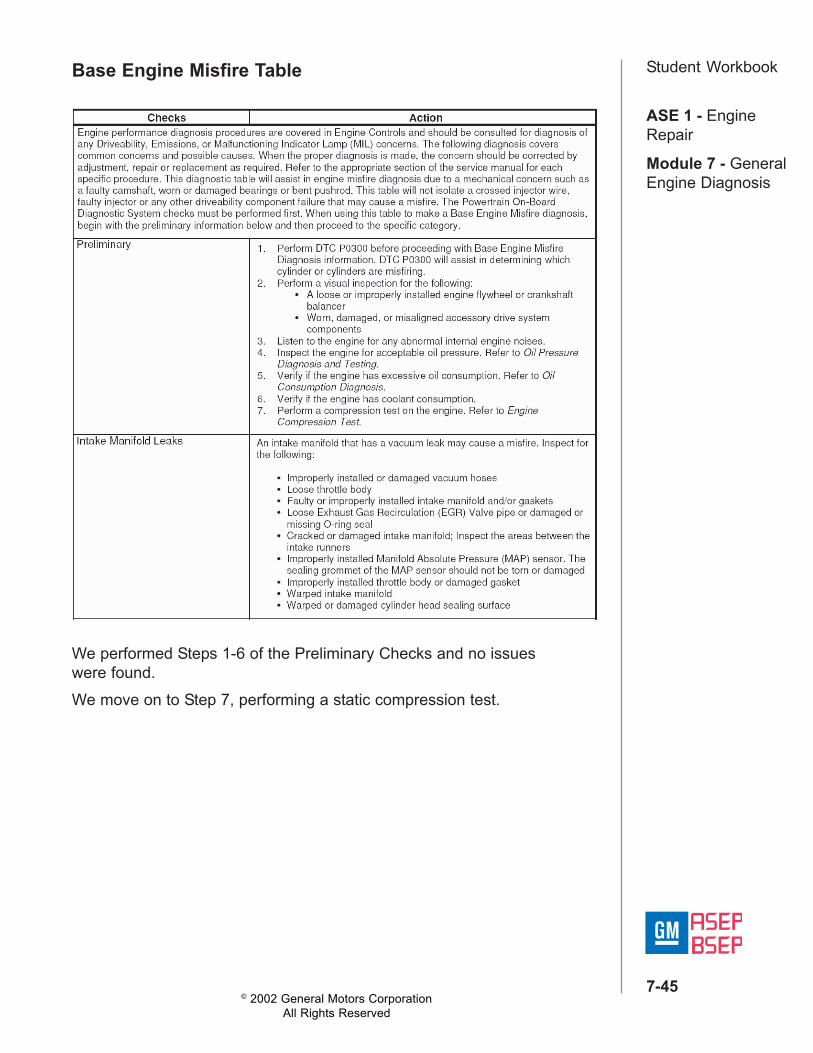
Base Engine Misfire ProcedureEngine performance diagnosis procedures are covered in Engine Controlsand should be consulted for diagnosis of any Driveability, Emissions, orMalfunctioning Indicator Lamp (MIL) concerns. The following diagnosiscovers common concerns and possible causes. When the properdiagnosis is made, the concern should be corrected by adjustment, repairor replacement as required. Refer to the appropriate section of the servicemanual for each specific procedure.This diagnostic procedure will assist in engine misfire diagnosis due to amechanical concern such as a faulty camshaft, worn or damaged bearingsor bent pushrod. This procedure will not isolate a crossed injector wire,faulty injector or any other driveability component failure that may cause amisfire.The Powertrain On-Board Diagnostic System checks must be performedfirst. When using this procedure to make a Base Engine Misfire diagnosis,begin with the preliminary information below and then proceed to thespecific category.
Preliminary1. Perform DTC P0300 before proceeding with Base Engine Misfire
Diagnosis information. DTC P0300 will assist in determining whichcylinder or cylinders are misfiring.
2. Perform a visual inspection for the following:• A loose or improperly installed engine flywheel or crankshaft
balancer.• Worn, damaged, or misaligned accessory drive system
components.3. Listen to the engine for any abnormal internal engine noises.
© 2002 General Motors CorporationAll Rights Reserved
ASE 1 - EngineRepair
Module 7 - GeneralEngine Diagnosis
7-38
Student Workbook4. Inspect the engine for acceptable oil pressure. Refer to Oil PressureDiagnosis and Testing.
5. Verify if the engine has excessive oil consumption. Refer to OilConsumption Diagnosis.
6. Verify if the engine has coolant consumption.7. Perform a compression test on the engine. Refer to Engine
Compression Test.
Intake Manifold LeaksAn intake manifold that has a vacuum leak may cause a misfire. Inspectfor the following:• Improperly installed or damaged vacuum hoses.• Loose throttle body.• Faulty or improperly installed intake manifold and/or gaskets.• Loose Exhaust Gas Recirculation (EGR) Valve pipe or damaged or
missing O-ring seal.• Cracked or damaged intake manifold; Inspect the areas between the
intake runners.• Improperly installed Manifold Absolute Pressure (MAP) sensor. The
sealing grommet of the MAP sensor should not be torn or damaged.• Improperly installed throttle body or damaged gasket.• Warped intake manifold.• Warped or damaged cylinder head sealing surface.
© 2002 General Motors CorporationAll Rights Reserved
ASE 1 - EngineRepair
Module 7 - GeneralEngine Diagnosis
7-39
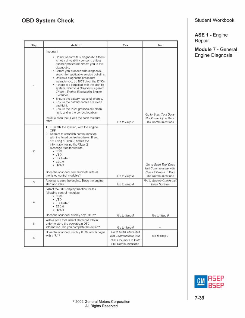
Student WorkbookOBD System Check
© 2002 General Motors CorporationAll Rights Reserved
ASE 1 - EngineRepair
Module 7 - GeneralEngine Diagnosis
7-40
Student Workbook
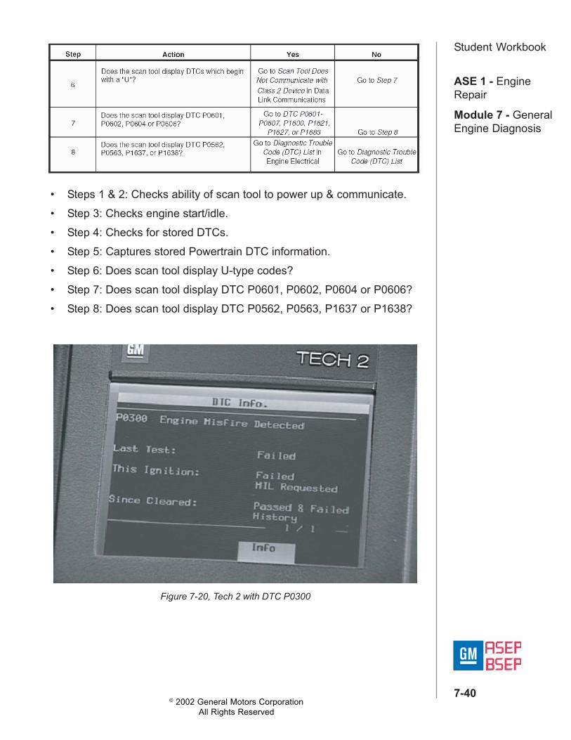
• Steps 1 & 2: Checks ability of scan tool to power up & communicate.• Step 3: Checks engine start/idle.• Step 4: Checks for stored DTCs.• Step 5: Captures stored Powertrain DTC information.• Step 6: Does scan tool display U-type codes?• Step 7: Does scan tool display DTC P0601, P0602, P0604 or P0606?• Step 8: Does scan tool display DTC P0562, P0563, P1637 or P1638?
Figure 7-20, Tech 2 with DTC P0300
© 2002 General Motors CorporationAll Rights Reserved
ASE 1 - EngineRepair
Module 7 - GeneralEngine Diagnosis
7-41
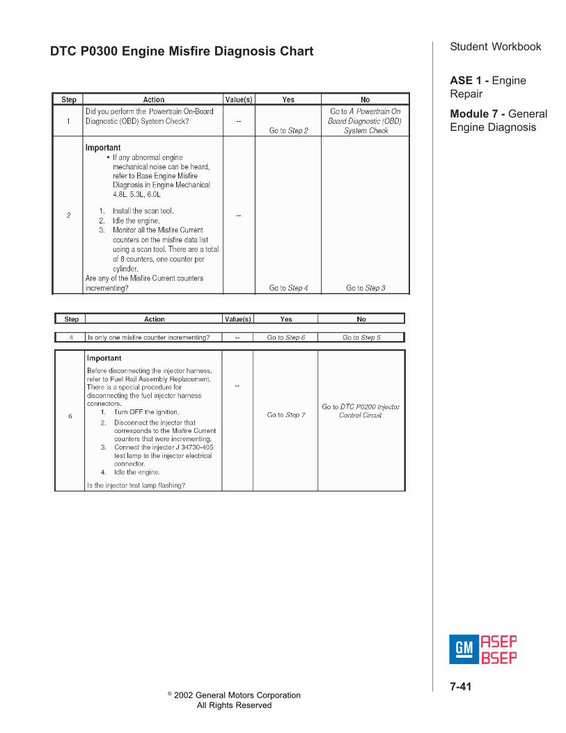
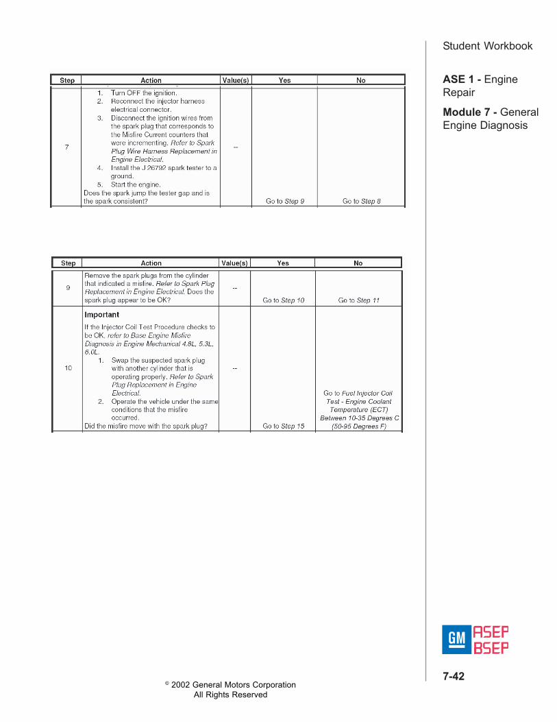
Student WorkbookDTC P0300 Engine Misfire Diagnosis Chart
© 2002 General Motors CorporationAll Rights Reserved
ASE 1 - EngineRepair
Module 7 - GeneralEngine Diagnosis
7-42
Student Workbook
© 2002 General Motors CorporationAll Rights Reserved
ASE 1 - EngineRepair
Module 7 - GeneralEngine Diagnosis
7-43
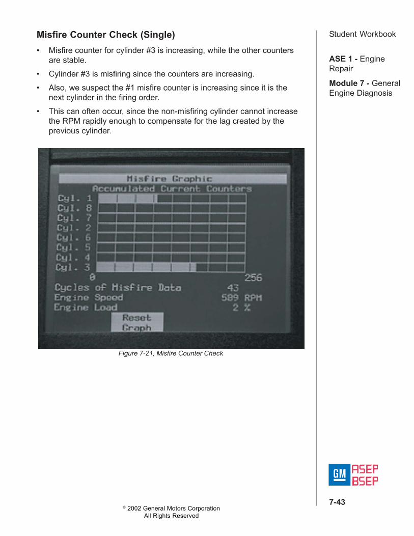
Student WorkbookMisfire Counter Check (Single)• Misfire counter for cylinder #3 is increasing, while the other counters
are stable.• Cylinder #3 is misfiring since the counters are increasing.• Also, we suspect the #1 misfire counter is increasing since it is the
next cylinder in the firing order.• This can often occur, since the non-misfiring cylinder cannot increase
the RPM rapidly enough to compensate for the lag created by theprevious cylinder.
Figure 7-21, Misfire Counter Check
© 2002 General Motors CorporationAll Rights Reserved
ASE 1 - EngineRepair
Module 7 - GeneralEngine Diagnosis
7-44
Student WorkbookTest Lamp J 26792 / ST 125 Spark TestingJ 26792/ST 125 Spark Tester results:• Spark tester showed spark at the cylinder• The spark plug appeared to be visually OK• The misfire did not move when we swapped spark plugs• At Step 6 we will use the injector test lamp• With ignition OFF, remove the connector for the #3 cylinder and install
the test lamp• For this vehicle, we will use J 34730-405• Start the engine and see what happens• At Step 7 we will be using the J 26792/ST 125 to check spark on #3
cylinder• Now, install J 26792/ST 125 spark tester; make sure it is connected to
a good ground• Start the engine• It appears OK, so let's move to Step 9 and look at the spark plug• Spark plugs appear okay• Let's move to Step 10 and swap the spark plugs
J 26792/ST 125 Spark Tester results:• Spark tester showed spark at the cylinder• The spark plug appeared to be visually OK• The misfire did not move when we swapped spark plugs
Injector Coil TestA "No" answer at Step 10 sends you to perform the fuel injector coil test.Results of Injector Coil test:• The results we have are within specifications• The chart then directs us to Symptoms• However, P0300 chart said that if injector coil test procedure checks to
be OK, refer to Base Engine Misfire DiagnosisThe results are within specification, so we move on to the base enginemisfire.
© 2002 General Motors CorporationAll Rights Reserved
ASE 1 - EngineRepair
Module 7 - GeneralEngine Diagnosis
7-45
Student WorkbookBase Engine Misfire Table
We performed Steps 1-6 of the Preliminary Checks and no issueswere found.We move on to Step 7, performing a static compression test.
© 2002 General Motors CorporationAll Rights Reserved
ASE 1 - EngineRepair
Module 7 - GeneralEngine Diagnosis
7-46
Student WorkbookLesson 4: Static Compression TestIntroductionAfter completing this unit, the technician will be able to apply concepts andprocedures to diagnose engine mechanical concerns utilizing the staticcompression test.
Objective• Identify the condition of the engine's piston rings, valves and head
gasket(s).
Static Compression TestTo prepare for an engine compression test:1. Charge the battery if the battery is not fully charged.2. Disable the ignition system.3. Disable the fuel injection system.4. Remove all the spark plugs.5. Block the throttle plate wide open.6. Start with the compression gauge at zero and crank the engine through
four compression strokes (four puffs).7. Make the compression check for each cylinder. Record the reading.8. If a cylinder has low compression, inject approximately 15 ml (one
tablespoon) of engine oil into the combustion chamber through thespark plug hole. Recheck the compression and record the reading.
9. The minimum compression in any one cylinder should not be less than70 percent of the highest cylinder. No cylinder should read less than690 kPa (100 psi). For example, if the highest pressure in any onecylinder were 1035 kPa (150 psi), the lowest allowable pressure forany other cylinder would be 725 kPa (105 psi) (1035 x 70% = 725)(150 x 70% = 105).
© 2002 General Motors CorporationAll Rights Reserved
ASE 1 - EngineRepair
Module 7 - GeneralEngine Diagnosis
7-47
Student Workbook• Normal — Compression builds up quickly and evenly to the specifiedcompression for each cylinder.
• Piston Rings Leaking — Compression is low on the first stroke.Compression then builds up with the following strokes but does notreach normal. Compression improves considerably when you add oil.
• Valves Leaking — Compression is low on the first stroke. Compressionusually does not build up on the following strokes. Compression doesnot improve much when you add oil.
• If two adjacent cylinders have lower than normal compression andinjecting oil into the cylinders does not increase the compression, thecause may be a head gasket leaking between the cylinders.
© 2002 General Motors CorporationAll Rights Reserved
ASE 1 - EngineRepair
Module 7 - GeneralEngine Diagnosis
7-48
Student WorkbookLesson 5: Running Compression TestIntroductionAfter completing this unit, the technician will be able to apply concepts andprocedures to diagnose engine mechanical concerns utilizing the runningcompression test.
ObjectiveIdentify the engine's ability to fill and evacuate the cylinder to produce theproper engine output during idle and loaded conditions.
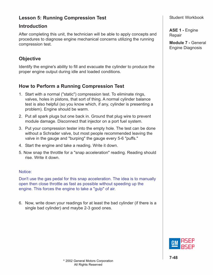
How to Perform a Running Compression Test1. Start with a normal ("static") compression test. To eliminate rings,
valves, holes in pistons, that sort of thing. A normal cylinder balancetest is also helpful (so you know which, if any, cylinder is presenting aproblem). Engine should be warm.
2. Put all spark plugs but one back in. Ground that plug wire to preventmodule damage. Disconnect that injector on a port fuel system.
3. Put your compression tester into the empty hole. The test can be donewithout a Schrader valve, but most people recommended leaving thevalve in the gauge and "burping" the gauge every 5-6 "puffs."
4. Start the engine and take a reading. Write it down.5. Now snap the throttle for a "snap acceleration" reading. Reading should
rise. Write it down.
Notice:Don't use the gas pedal for this snap acceleration. The idea is to manuallyopen then close throttle as fast as possible without speeding up theengine. This forces the engine to take a "gulp" of air.
6. Now, write down your readings for at least the bad cylinder (if there is asingle bad cylinder) and maybe 2-3 good ones.
© 2002 General Motors CorporationAll Rights Reserved
ASE 1 - EngineRepair
Module 7 - GeneralEngine Diagnosis
7-49
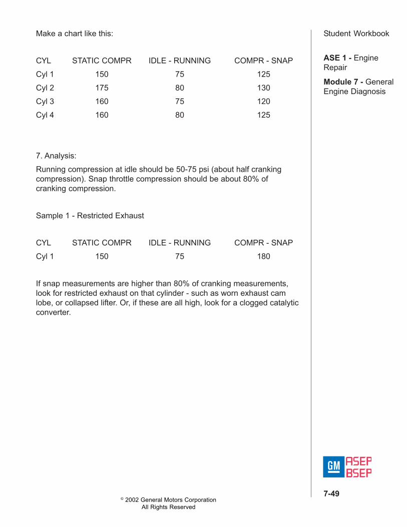
Student WorkbookMake a chart like this:
CYL STATIC COMPR IDLE - RUNNING COMPR - SNAPCyl 1 150 75 125Cyl 2 175 80 130Cyl 3 160 75 120Cyl 4 160 80 125
7. Analysis:Running compression at idle should be 50-75 psi (about half crankingcompression). Snap throttle compression should be about 80% ofcranking compression.
Sample 1 - Restricted Exhaust
CYL STATIC COMPR IDLE - RUNNING COMPR - SNAPCyl 1 150 75 180
If snap measurements are higher than 80% of cranking measurements,look for restricted exhaust on that cylinder - such as worn exhaust camlobe, or collapsed lifter. Or, if these are all high, look for a clogged catalyticconverter.
© 2002 General Motors CorporationAll Rights Reserved
ASE 1 - EngineRepair
Module 7 - GeneralEngine Diagnosis
7-50
Student WorkbookLesson 6: Cylinder Leakage TestIntroductionAfter completing this unit, the technician will be able to apply concepts andprocedures to diagnose engine mechanical concerns utilizing the cylinderleakage test.
ObjectiveThe cylinder leakage test may be used in conjunction with the enginecompression test to isolate the cause of leaking cylinders.
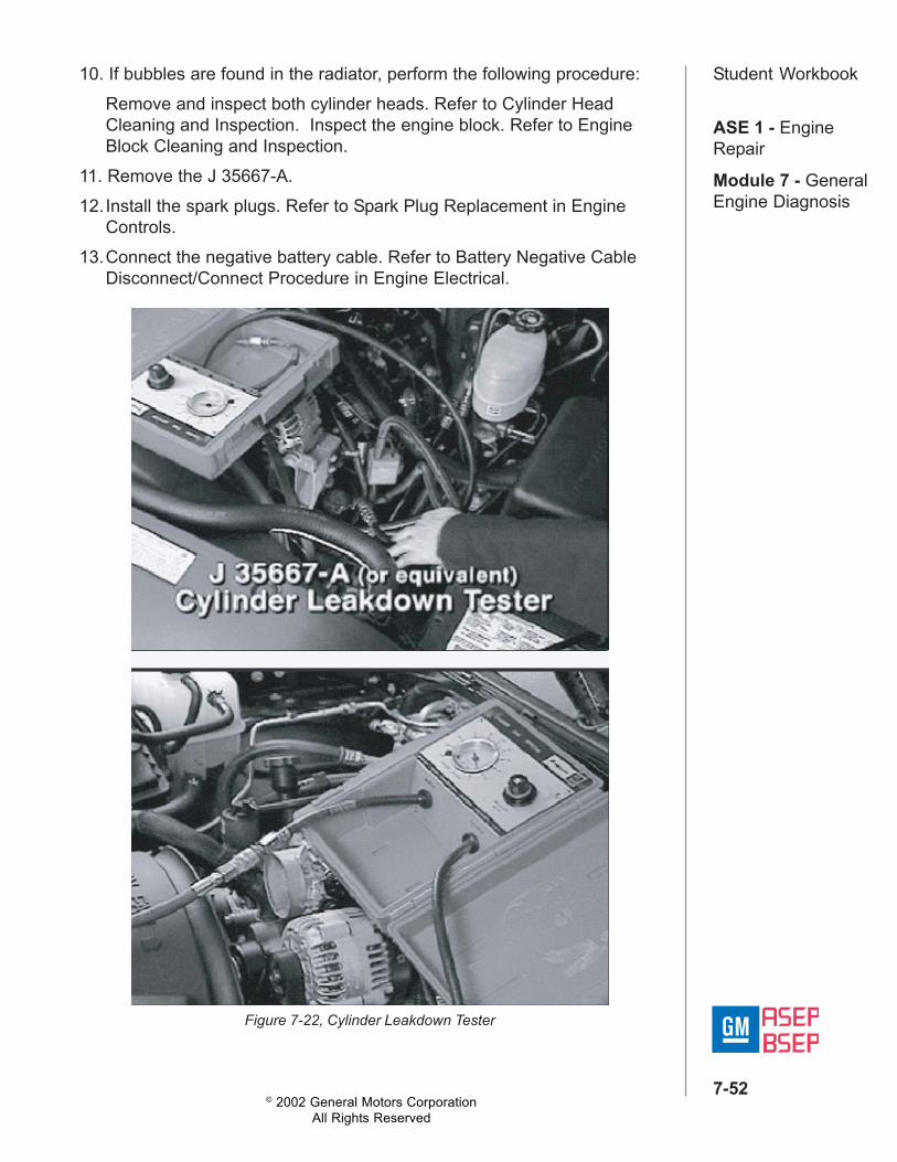
Cylinder Leakage Test - Testing ProcedureTools Required - J 35667-A Cylinder Leakdown Tester
With the use of air pressure, a cylinder leakage test will aid in thediagnosis. Use the cylinder leakage test in conjunction with the enginecompression test in order to isolate the cause of leaking cylinders.
Caution:Before servicing any electrical component, the
ignition key must be in the OFF or LOCK positionand all electrical loads must be OFF, unless
instructed otherwise in these procedures. If a toolor equipment could easily come in contact with alive exposed electrical terminal, also disconnectthe negative battery cable. Failure to follow these
precautions may cause personal injury and/ordamage to the vehicle or its components.
© 2002 General Motors CorporationAll Rights Reserved
ASE 1 - EngineRepair
Module 7 - GeneralEngine Diagnosis
7-51
Student Workbook1. Disconnect the negative battery cable.2. Remove the spark plugs. Refer to Spark Plug Replacement in Engine
Controls.3. Install the J 35667-A4. Measure each cylinder on the compression stroke, with both valves
closed.
Notice:Hold the crankshaft balancer bolt in order to prevent piston movement.
5. Apply air pressure, using the J 35667-A. Refer to the manufacturer'sinstructions.
6. Record the cylinder leakage readings for each cylinder.
Notice:Normal cylinder leakage is from 12 to 18 percent. Make a note of anycylinder with more leakage than the other cylinders. Any cylinder with 30percent leakage or more requires service.
7. Inspect the 4 primary areas in order to properly diagnose a leakingcylinder.
8. If air is heard from the intake or exhaust system, perform the followingprocedure:Remove the valve rocker arm cover of the suspect cylinder head.Ensure that both valves are closed. Inspect the cylinder head for abroken valve spring. Remove and inspect the suspect cylinder head.Refer to Cylinder Head Cleaning and Inspection.
9. If air is heard from the crankcase system at the crankcase (oil fillertube), perform the following procedure:Remove the piston from the suspect cylinder. Inspect the piston andconnecting rod assembly. Refer to Piston, Connecting Rod, andBearings Cleaning and Inspection. Inspect the engine block. Refer toEngine Block Cleaning and Inspection.
© 2002 General Motors CorporationAll Rights Reserved
ASE 1 - EngineRepair
Module 7 - GeneralEngine Diagnosis
7-52
Student Workbook10. If bubbles are found in the radiator, perform the following procedure:Remove and inspect both cylinder heads. Refer to Cylinder HeadCleaning and Inspection. Inspect the engine block. Refer to EngineBlock Cleaning and Inspection.
11. Remove the J 35667-A.12.Install the spark plugs. Refer to Spark Plug Replacement in Engine
Controls.13.Connect the negative battery cable. Refer to Battery Negative Cable
Disconnect/Connect Procedure in Engine Electrical.
Figure 7-22, Cylinder Leakdown Tester
© 2002 General Motors CorporationAll Rights Reserved
ASE 1 - EngineRepair
Module 7 - GeneralEngine Diagnosis
7-53
Student WorkbookLesson 7: Restricted Exhaust Test
Introduction
After completing this unit, the technician will be able to apply concepts andprocedures to diagnose engine mechanical concerns utilizing therestricted exhaust test.
ObjectiveIdentify an engine mechanical concern related to a restricted exhaustsystem.
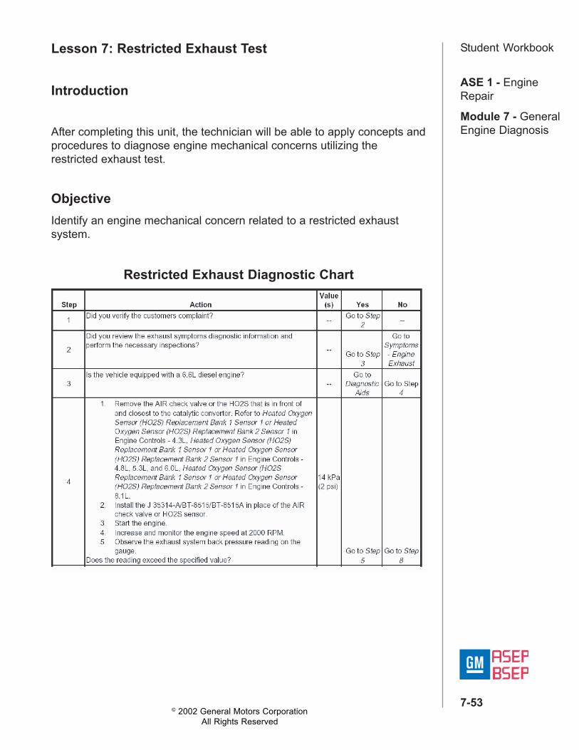
Restricted Exhaust Diagnostic Chart
© 2002 General Motors CorporationAll Rights Reserved
ASE 1 - EngineRepair
Module 7 - GeneralEngine Diagnosis
7-54
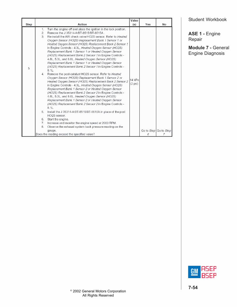
Student Workbook
© 2002 General Motors CorporationAll Rights Reserved
ASE 1 - EngineRepair
Module 7 - GeneralEngine Diagnosis
7-55
Student WorkbookLesson 8: Vacuum TestIntroductionAfter completing this unit, the technician will be able to apply concepts andprocedures to diagnose engine mechanical concerns utilizing the vacuumtest.
ObjectiveDescribe the procedure to check engine vacuum and identify thesource(s) of incorrect vacuum readings.
Vacuum TestThe intake stroke of the piston creates a vacuum in the manifold. Vacuumis any pressure lower than the atmospheric pressure. Monitoring themanifold vacuum is a good indicator of the engine's ability to runefficiently. Typical engine vacuum is a steady reading between 15 and 22inches of mercury with the engine at normal operating temperatures, idle,and in drive.
Vacuum Test LimitationsThe amount of vacuum formed in the manifold depends on several things.• First, the cylinders must be sealed. If a cylinder has high leakage, it
will not produce sufficient vacuum to draw in the air/fuel mixture.• If the manifold is not sealed, vacuum will be lower than normal.• Vacuum hoses and accessories may leak, causing lower manifold
vacuum.• When the throttle plate is open and atmospheric pressure enters the
manifold, vacuum is lower.• If the engine has higher compression, it will have 1 to 2 inches of
mercury higher vacuum.• For every 1,000 feet of altitude above sea level, vacuum will be
lowered by 1 inch of mercury.• A high lift cam or considerable valve overlap will produce a slightly
lower, erratic needle reading on the gauge.• Vacuum changes with load, so operating accessories when monitoring
vacuum will change the readings.
© 2002 General Motors CorporationAll Rights Reserved
ASE 1 - EngineRepair
Module 7 - GeneralEngine Diagnosis
7-56
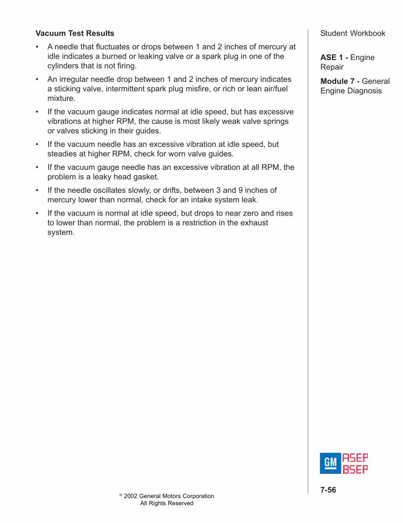
Student WorkbookVacuum Test Results• A needle that fluctuates or drops between 1 and 2 inches of mercury at
idle indicates a burned or leaking valve or a spark plug in one of thecylinders that is not firing.
• An irregular needle drop between 1 and 2 inches of mercury indicatesa sticking valve, intermittent spark plug misfire, or rich or lean air/fuelmixture.
• If the vacuum gauge indicates normal at idle speed, but has excessivevibrations at higher RPM, the cause is most likely weak valve springsor valves sticking in their guides.
• If the vacuum needle has an excessive vibration at idle speed, butsteadies at higher RPM, check for worn valve guides.
• If the vacuum gauge needle has an excessive vibration at all RPM, theproblem is a leaky head gasket.
• If the needle oscillates slowly, or drifts, between 3 and 9 inches ofmercury lower than normal, check for an intake system leak.
• If the vacuum is normal at idle speed, but drops to near zero and risesto lower than normal, the problem is a restriction in the exhaustsystem.
© 2002 General Motors CorporationAll Rights Reserved
ASE 1 - EngineRepair
Module 7 - GeneralEngine Diagnosis
7-57
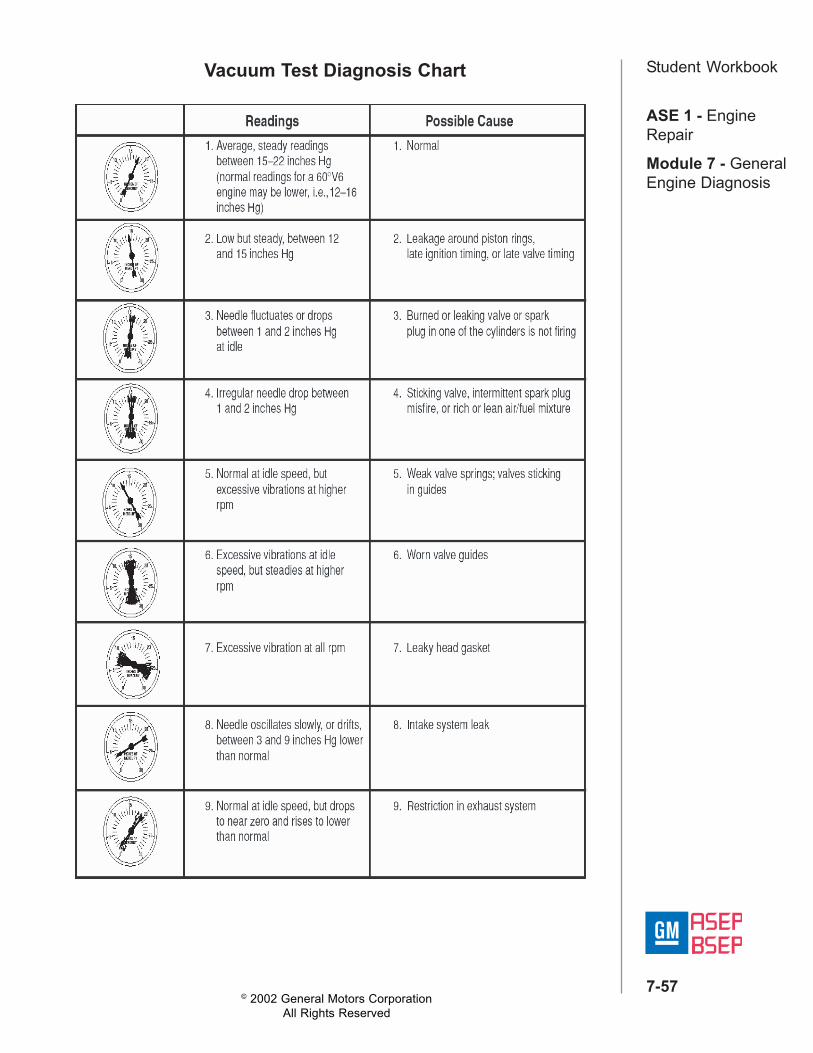
Student WorkbookVacuum Test Diagnosis Chart
© 2002 General Motors CorporationAll Rights Reserved
ASE 1 - EngineRepair
Module 7 - GeneralEngine Diagnosis
7-58
Student WorkbookLesson 9: Oil Pressure TestIntroductionAfter completing this unit, the technician will be able to apply concepts andprocedures to diagnose engine oil pressure concerns.
ObjectiveDescribe the procedure to check oil pressure and identify the sources oflow oil pressure.
Engine Oil Functions• Provides lubrication to moving parts to prevent damage and
overheating.• Supplies operating pressure to components like valve lifters and the
camshaft position actuator on the 4200 engine.• Cools moving components.• Provides sealing and cleaning.Because the oil performs various functions, sufficient flow must beprovided by the oil system to make certain that sufficient oil is delivered toengine components.There are several checks that must be performed to determine if the oiland the oil system are performing the necessary functions.
Initial Engine Oil ChecksCheck the level:• If the level is too low, the lubrication system may not be able to provide
sufficient flow.• If the fluid is too high, it can be an indicator of contamination (fuel,
water or coolant).
Check the condition:• Oil properties degrade over time.• Combustion gases escaping past the piston rings can contaminate
the oil.
© 2002 General Motors CorporationAll Rights Reserved
ASE 1 - EngineRepair
Module 7 - GeneralEngine Diagnosis
7-59
Student WorkbookCheck vehicle oil gauge (if equipped):• A good initial check of oil is to look at the vehicle oil pressure gauge.• However, the gauge may not be as sensitive as a mechanical gauge
connected directly to the system.
There are two important points that you should remember aboutengine oil:• At 6 psi, the oil pressure light turns on.• Normal oil consumption is 1 quart per 2000 miles.• During the break-in period, this can be higher.
Oil Pressure Test• Before connecting the gauge, perform a few preliminary inspections:
– Check for oil pan damage and look for oil leaks.– Observe and note abnormal noises.
• Install the gauge and check pressure using service procedures– Some applications require special tools
• Compare gauge readings to specifications– Check oil pressure cold and hot.
Remember, you can check both the upper end and the lower end fordiagnostic purposes.
Oil Pressure Checking• Service procedures generally select pressure tap near oil pump outlet
to provide initial pressure produced by pump.• Tells you if pump is operating within specifications, but not what is
happening in other parts of engine.• If pump is producing insufficient pressure at this tap, look for
restrictions or leakage in the lower engine circuit.• Can also check the pressure further up oil circuit on many engines
when valve train is producing noise but oil pressure near the pump iscorrect
• If there is restriction or leak in the upper valve train circuits, valve trainwill have insufficient lubrication. Pressure check this portion of thecircuit for lower pressure. Closely inspect valve train components fordamage.
© 2002 General Motors CorporationAll Rights Reserved
ASE 1 - EngineRepair
Module 7 - GeneralEngine Diagnosis
7-60
Student Workbook
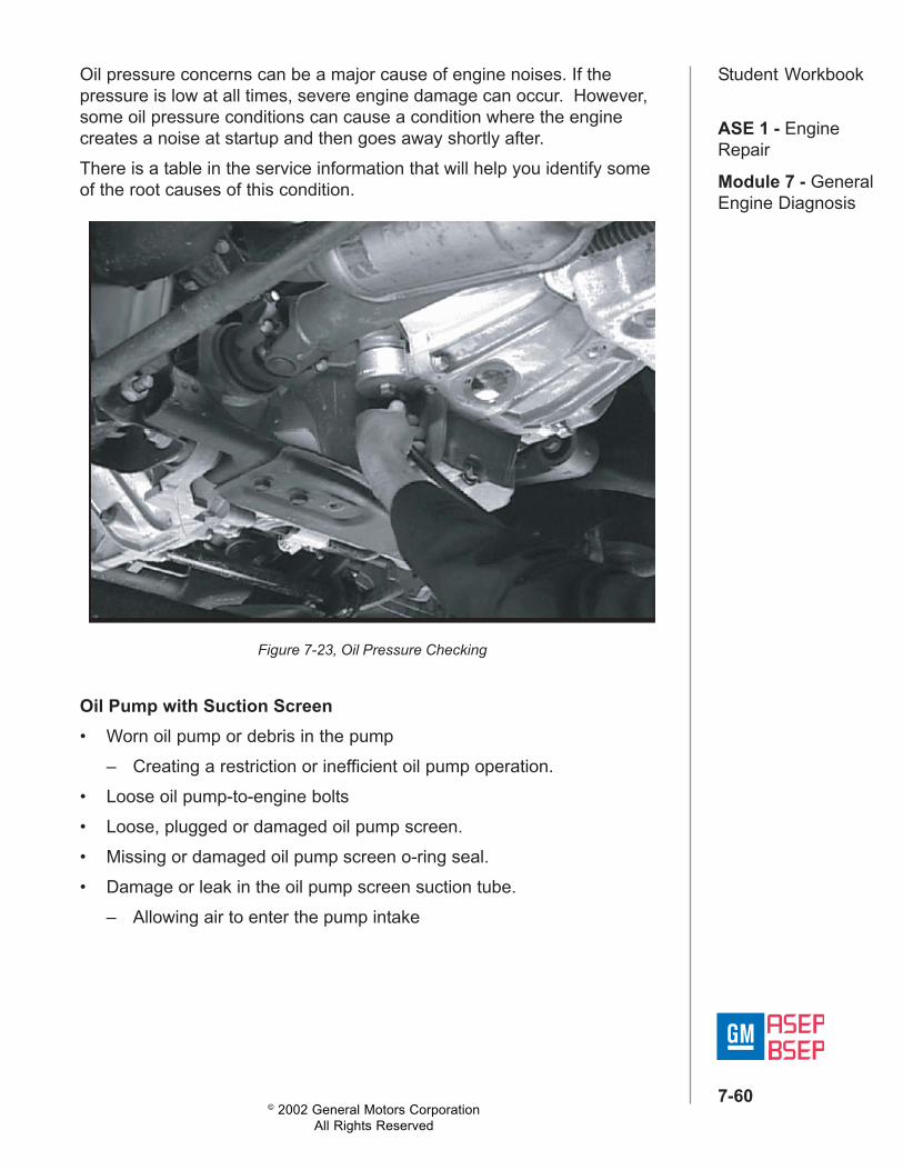
Figure 7-23, Oil Pressure Checking
Oil pressure concerns can be a major cause of engine noises. If thepressure is low at all times, severe engine damage can occur. However,some oil pressure conditions can cause a condition where the enginecreates a noise at startup and then goes away shortly after.There is a table in the service information that will help you identify someof the root causes of this condition.
Oil Pump with Suction Screen• Worn oil pump or debris in the pump
– Creating a restriction or inefficient oil pump operation.• Loose oil pump-to-engine bolts• Loose, plugged or damaged oil pump screen.• Missing or damaged oil pump screen o-ring seal.• Damage or leak in the oil pump screen suction tube.
– Allowing air to enter the pump intake
© 2002 General Motors CorporationAll Rights Reserved
ASE 1 - EngineRepair
Module 7 - GeneralEngine Diagnosis
7-61
Student Workbook
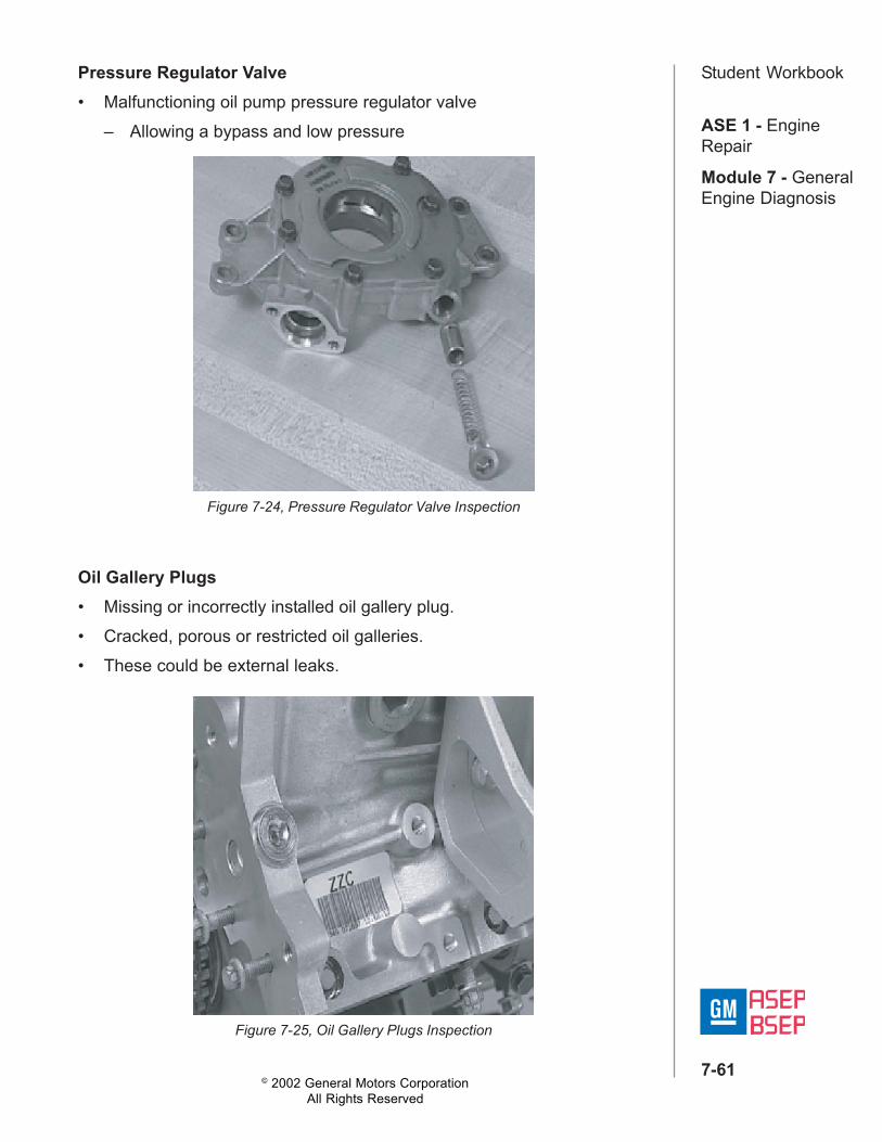
Figure 7-24, Pressure Regulator Valve Inspection
Pressure Regulator Valve• Malfunctioning oil pump pressure regulator valve
– Allowing a bypass and low pressure
Figure 7-25, Oil Gallery Plugs Inspection
Oil Gallery Plugs• Missing or incorrectly installed oil gallery plug.• Cracked, porous or restricted oil galleries.• These could be external leaks.
© 2002 General Motors CorporationAll Rights Reserved
ASE 1 - EngineRepair
Module 7 - GeneralEngine Diagnosis
7-62
Student WorkbookLesson 10: Engine Speed-Related Vibrations
IntroductionAfter completing this unit, the technician will be able to apply concepts andprocedures to diagnose engine speed-related vibrations.
ObjectiveDescribe Engine Speed-Related Vibration Firing Frequencies.
Isolating Vibrations• Duplicate the vibration while the vehicle is on an inspection-type hoist
(either a front-end rack or similar hoist that supports the vehicle at curbheight).
• While the vibration is present, find the area(s) of the vehicle that areexcited or responding to the vibration.
• Look closely for witness marks due to a rubbing component.• Once an area of the vehicle has been pinpointed, the component
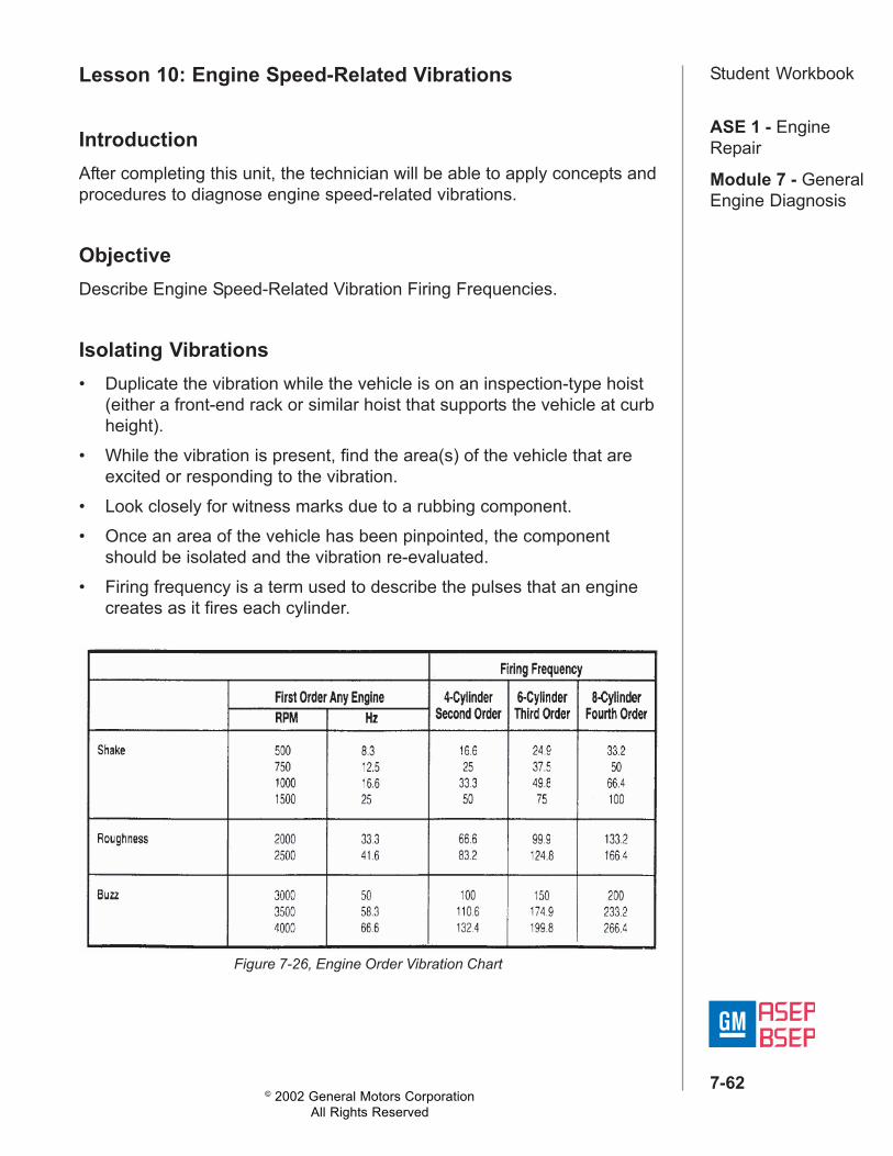
should be isolated and the vibration re-evaluated.• Firing frequency is a term used to describe the pulses that an engine
creates as it fires each cylinder.
Figure 7-26, Engine Order Vibration Chart
© 2002 General Motors CorporationAll Rights Reserved
ASE 1 - EngineRepair
Module 7 - GeneralEngine Diagnosis
7-63
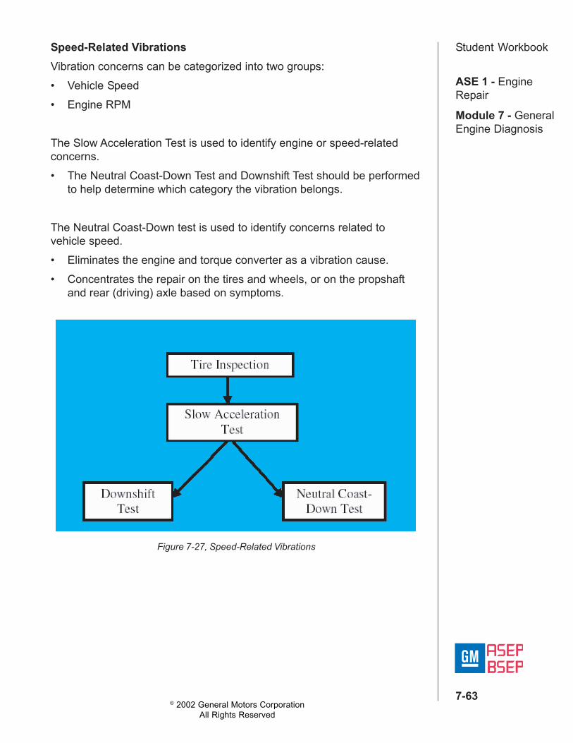
Student WorkbookSpeed-Related VibrationsVibration concerns can be categorized into two groups:• Vehicle Speed• Engine RPM
The Slow Acceleration Test is used to identify engine or speed-relatedconcerns.• The Neutral Coast-Down Test and Downshift Test should be performed
to help determine which category the vibration belongs.
The Neutral Coast-Down test is used to identify concerns related tovehicle speed.• Eliminates the engine and torque converter as a vibration cause.• Concentrates the repair on the tires and wheels, or on the propshaft
and rear (driving) axle based on symptoms.
Figure 7-27, Speed-Related Vibrations
© 2002 General Motors CorporationAll Rights Reserved
ASE 1 - EngineRepair
Module 7 - GeneralEngine Diagnosis
7-64
Student WorkbookNotice:If the concern is vehicle-speed related only; that it appears at the samemph regardless of the engine speed, the Neutral Run-Up Test and BrakeTorque Test probably will not apply.
Notice:The Neutral Run-Up Test and Brake Torque Test are used for enginespeed-related vibrations.
Engine Speed-Related VibrationsThe Downshift Test and Neutral Run-Up Test are used to identify enginespeed related concerns.
Brake Torque TestIdentifies engine-speed-related vibrations not revealed by the NeutralRun-Up Test.This test also works for vibrations that are sensitive to engine load ortorque.
• If the vibration returns at the same rpm, the engine and torqueconverter are the most probable causes
• In some cases, a vibration may be sensitive to torque or engine load• These vibrations can be the most difficult to diagnose, and may require
additional testing
The Brake Torque Test identifies engine speed-related vibrations, notrevealed by the Neutral Run-Up Test.
Neutral Run-Up TestIdentifies engine speed-related vibrations.Use this test whenever customer expresses a concern about vibration atidle, or as a follow-up to Downshift Test.
© 2002 General Motors CorporationAll Rights Reserved
ASE 1 - EngineRepair
Module 7 - GeneralEngine Diagnosis
7-65
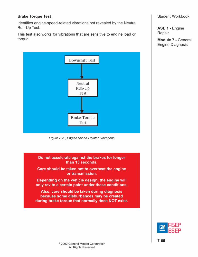
Student WorkbookBrake Torque TestIdentifies engine-speed-related vibrations not revealed by the NeutralRun-Up Test.This test also works for vibrations that are sensitive to engine load ortorque.
Figure 7-28, Engine Speed-Related Vibrations
Do not accelerate against the brakes for longerthan 15 seconds.
Care should be taken not to overheat the engineor transmission.
Depending on the vehicle design, the engine willonly rev to a certain point under these conditions.
Also, care should be taken during diagnosisbecause some disburbances may be created
during brake torque that normally does NOT exist.
© 2002 General Motors CorporationAll Rights Reserved
ASE 1 - EngineRepair
Module 7 - GeneralEngine Diagnosis
7-66
Student WorkbookExercise 7-1Read each question carefully and choose the correct response.
1. A compression test is performed on an engine. Technician A states thatthe lowest cylinder should NOT be les than 70% of the highestreading. Technician B states that you should consult serviceinformation for the correct pressure specifications. Which technician iscorrect? (3)a. Technician Ab. Technician Bc. Both technicians are correctd. Neither technician is correct.
2. For a properly running engine, a good vacuum reading should be______________.a. 10-14 inches of mercuryb. Steady needle, 17-20 inches of waterc. Steady needle, 17-20 inches of mercuryd. Fluctuating gauge between 15-17 inches of water
3. A diagram shows a vacuum hose connected to “ported vacuum.” Thismeans the hose should be connected _____________.a. To the vacuum reservoir tankb. To the intake manifoldc. Below the throttle plated. Above the throttle plate
4. All of the following engine mechanical conditions can be diagnosedwith a leakage test EXCEPT:a. Burned exhaust valveb. Cracked or warped headc. Worn cam lobesd. Worn piston rings
© 2002 General Motors CorporationAll Rights Reserved
ASE 1 - EngineRepair
Module 7 - GeneralEngine Diagnosis
7-67
Student Workbook5. During a cylinder leakage test you find air coming out around thecylinder head valve cover. All of the following could be the causeEXCEPT:a. Blown head gasketb. Cracked blockc. Warped headd. Worn piston rings
6. A leakage test on cylinder 3 shows air coming from cylinder 5, and viceversa. These results mean which of the following?a. Leakage head gasketb. Hole in piston 3c. Leaky exhaust valved. Leaky intake valve
7. A customer is concerned because oil is leaking from the middle of theirvehicle engine compartment. The source of the leak cannot bedetermined visually. How should the source of the leak be pinpointed?a. Overfill all the fluidsb. Inspect sealsc. Replace all the sealsd. Use fluorescent dye
8. Which of the following devices is used with dye to help find leaks?a. Fluorescent lightb. Infrared camerac. Ultraviolet lightd. Neon light
9. When using the black light and dye method to perform oil leakdetection, the dye will appear _______ under the light.a. Redb. Yellowc. Blued. Black
© 2002 General Motors CorporationAll Rights Reserved
ASE 1 - EngineRepair
Module 7 - GeneralEngine Diagnosis
7-68
Student Workbook10.The purpose of the oil pump is to ______________.a. clean the oilb. cool the oilc. pressurize the oild. control oil pressure
11. Which of the following is NOT a cause of low or no oil pressure?a. Improper oil viscosityb. Low oil levelc. Low cylinder compressiond. Slow idle speed
12.Which of the following can NOT be the cause of low engine oilpressure?a. Loose crankshaft balancer boltb. Loose oil pump mounting boltsc. Missing pickup o-ringd. Broken valve lifters
13.On a V-type engine with dual overhead cams, compression is found tobe low on all cylinders in one bank only. The most likely cause wouldbe _____________.a. jumped timing chainb. incorrect ignition timingc. leaking head gasketd. broken crank gear
14.If camshaft timing were incorrect, all of the following might be the resultEXCEPT ___________.a. no startb. lack of powerc. possible damage to valves or pistons (depending on the
application)d. worn camshaft lobes
© 2002 General Motors CorporationAll Rights Reserved
ASE 1 - EngineRepair
Module 7 - GeneralEngine Diagnosis
7-69
Student Workbook15.When verifying camshaft timing, the timing marks should be at whichof the following positions?a. All at 12 o’clockb. Pointing at each otherc. Lined up according to service informationd. Ignored, as they are only for use in ignition timing
16.Valve train noises occur at _______ speed of the engine.a. 1/4b. 1/2c. 3/4d. the same
17.When checking the Camshaft position actuator movement,approximately how much movement should there be?a. 5-8 mmb. 10-11 mmc. 14-15 mmd. 17-18 mm
18.A customer brings in a 1996 Oldsmobile Aurora with a 4.0L V8. Thecustomer is concerned because oil is leaking from the middle of theengine compartment. Which of the following processes should be usedto solve the concern?a. System verification processb. Strategy-based diagnosticsc. Testing based diagnosticsd. Strategy verification process
19.A customer brings in a 1996 Oldsmobile Aurora with a 4.0L V8. Thecustomer is concerned because oil is leaking from he middle of theengine compartment. Which of the following is the first step?a. Check bulletinsb. Verify the customer concernc. Check vehicle historyd. Start OBD system check
© 2002 General Motors CorporationAll Rights Reserved
ASE 1 - EngineRepair
Module 7 - GeneralEngine Diagnosis
7-70
Student Workbook20.A customer brings in a vehicle with an intermittent misfire concern. TheMIL is illuminated. Which of the following is the first step in diagnosingthis concern using a strategy based diagnostic process?a. Verify concernb. Check service diagnosticsc. Verify bulletinsd. Conduct preliminary checks
21.A customer brings in a 1999 Cadillac Eldorado with a 4.6L V8 VIN YROP Code LD8, concerned because it misfires at all times. The MIL isilluminated. All of the following are quick checks EXCEPT:a. Checking for loose or missing plug wireb. Looking for damaged coilc. Listening for engine noisesd. Checking for vehicle history
22.After performing an engine vacuum and a compression test, the testresults are reviewed and oil is added to cylinders 3 and 5. If thecompression remains the same, which of the following tests isperformed next?a. Compression testb. Cylinder leakage testc. Fuel pressure testd. Oil pressure test
23.A compression test shows that one cylinder is too low. A cylinderleakage test shows that there is too much leakage. During the test, aircould be heard coming from the tailpipe. Which of the following couldbe the cause?a. Broken piston ringb. Blown head gasketc. Leaking exhaust gasketd. Leaking exhaust valve
© 2002 General Motors CorporationAll Rights Reserved
ASE 1 - EngineRepair
Module 7 - GeneralEngine Diagnosis
7-71
Student Workbook24.An irregular thud or click loudest on deceleration is most likely relatedto the ____________.a. main bearingsb. flywheelc. valve traind. harmonic balancer
25.In engine noise diagnosis, noises synchronized to one-half the enginespeed are normally associated with the __________.a. main bearingsb. connecting rod bearingsc. pistonsd. valve train
26.A high frequency light-knocking sound occurring at the same intensityregardless of engine load is related to the _______________.a. flywheelb. connecting rod bearingsc. main bearingsd. timing chain and sprocket
27.Top engine cleaner is the recommended GM cleaner for which of thefollowing conditions:a. Leaking oil sealsb. Carbon build upc. Coolant system leaksd. Defective head gasket
28.When removing carbon build up, the top engine cleaner should beallowed to work inside the engine for at least ________ minutes,before starting the engine to remove the cleaner:a. 5b. 10c. 15d. 20
© 2002 General Motors CorporationAll Rights Reserved
ASE 1 - EngineRepair
Module 7 - GeneralEngine Diagnosis
7-72
Student Workbook29.The injector test lamp tests which of the following:a. The mechanical side of the injectorb. The fuel pumpc. The PCM and harnessd. The fuel pressure regulator
30.A customer is concerned about a knocking noise in the front of theirvehicle on start up. The first step of the SBD process is __________.a. verify the concernb. preliminary checksc. check vehicle historyd. check bulletins
31.In reference to low or no oil pressure, Technician A says that it couldbe caused by worn main bearings. Technician B says that worn ringswill cause the same. Which technician is correct?a. Technician Ab. Technician Bc. Both technicians are correctd. Neither technician is correct
32.During which of the following engine operating conditions will carbonbuild up cause a noise concern?a. Cold engine operationb. Engine overheating conditionc. Normal operating conditionsd. All engine operating conditions
33.Which of the following noises would usually be associated with abalance shaft concern?a. Rattle noiseb. Whinec. Knockd. Growl
© 2002 General Motors CorporationAll Rights Reserved
ASE 1 - EngineRepair
Module 7 - GeneralEngine Diagnosis
7-73
Student Workbook34.A damaged flywheel will usually create a knocking noise during whichof the following conditions:a. accelerationb. decelerationc. idled. part throttle cruise
35.Which of the following is a cause of low oil pressure?a. Too much oilb. Broken piston oil ringc. Plugged oil pump pickup screend. Oil pan leak
36.A technician is measuring engine vacuum on an engine. The readingsare 20 inches of vacuum at idle and 10 inches of vacuum at 2000RPM. This would indicate _______________.a. late valve timingb. restricted exhaustc. restriction in air intake systemd. a vacuum leak at the intake manifold
37.A plugged catalytic converter will cause a vacuum gauge to _______.a. read a steady 16 inches at idleb. fluctuate between 16 and 21 inches at idlec. read a steady 25 inches at idled. read a gradual loss of vacuum
38.When checking engine vacuum, idle has 15 inches and whenincreasing RPM’s, vacuum steadily drops off and engine stalls. Thismeans the _____________.a. catalytic converter is restrictedb. muffler has been replaced with test pipec. vacuum reading is normald. engine timing is retarded
© 2002 General Motors CorporationAll Rights Reserved
ASE 1 - EngineRepair
Module 7 - GeneralEngine Diagnosis
7-74
Student Workbook39.A vacuum test shows low, but steady vacuum. Which of the following isthe least likely cause?a. Weak valve springsb. Leakage around piston ringsc. Late ignition timingd. Vacuum leak
40.For most engines, normal engine vacuum at idle should be _______inches Hg.a. 25-29b. 15-22c. 7-12d. 5-7
41.When performing an engine vacuum test, the test shows the needlefluctuating between 12 and 17 inches Hg. Which of the following testsshould be performed next?a. Compression testb. Engine vacuum testc. Fuel pressure testd. Leakage test
42.For every _______ feet of altitude above sea level, vacuum will belowered by 1 in-Hg.a. 500b. 1,000c. 5,000d. 10,000
43.While doing a cylinder leakage test, the technician finds air escapingout the dipstick tube. The most likely cause would be ____________.a. worn piston ringsb. burned intake valvec. blown head gasketd. burned exhaust valve
© 2002 General Motors CorporationAll Rights Reserved
ASE 1 - EngineRepair
Module 7 - GeneralEngine Diagnosis
7-75
Student Workbook44.A car runs rough and backfires through the throttle body. Compressionis checked and one cylinder is low. The most likely cause of theproblem is a/an:a. faulty intake valveb. burned exhaust valvec. EGR valve failured. blown head gasket
45.During a compression test, you get a reading of 80 PSI dry and140 PSI wet on the #4 cylinder. All other cylinders are about 145 PSIwet and dry. Which of these readings most likely indicate a/an:a. blown head gasket between cylinder #3 and cylinder #4b. bad intake valve on cylinder #4c. bad exhaust valve on cylinder #4d. worn piston ring on cylinder #4
46.During an engine compression test, how many compression strokesare needed to obtain an accurate reading on the gauge?a. Fourb. Threec. Twod. One
47.An engine compression test indicates compression is low on the firststroke, and does NOT build up, even with the addition of oil. Which ofthe following parts could be the cause of this concern?a. Valve stem sealsb. Piston ringsc. Valvesd. Intake manifold
© 2002 General Motors CorporationAll Rights Reserved
ASE 1 - EngineRepair
Module 7 - GeneralEngine Diagnosis
7-76
Student Workbook48.An engine compression test indicates compression is low on the firststroke, but builds with successive strokes, especially when oil isadded. Which of the following parts is most likely the cause of thisconcern?a. Valve stem sealsb. Piston ringsc. Valvesd. Head gasket
49.When performing an engine compression test, if the compression islow on the first stroke, does NOT build on successive strokes, anddoes NOT increase with oil added, the most likely problem is/are the:a. Valvesb. Piston ringsc. Intake manifoldd. Valve stem seals
50.During a cylinder leakage test, you notice air escaping past the throttleplate. This means there is a leak at the __________.a. Piston ringsb. Intake valvec. Intake manifold gasketd. Head gasket
51.During the leakage test, listen for air leakage in all of the followinglocations EXCEPT the:a. Throttle bodyb. Tailpipec. Crankcase or valve coverd. Transmission
© 2002 General Motors CorporationAll Rights Reserved
ASE 1 - EngineRepair
Module 7 - GeneralEngine Diagnosis
7-77
Student Workbook52.Which of the following is the MOST likely symptom of a leaky valvewhen performing a cylinder leak down test?a. Hissing in crankcaseb. Bubbles in radiatorc. Hissing in intake or exhaustd. Hissing at the spark plug hole
53.When doing a compression test, all cylinders are found to be low.Which of the following would be the most likely cause?a. Advanced ignition timingb. Burned intake valvesc. Late valve timingd. Carbon build up in the cylinder
54.A leak in the hose on the bottom radiator tank to the water pump willallow coolant to leak and:a. Air to enterb. The thermostat to failc. Increase pressure in capd. The hose to fail
55.Technician A says that too high an oil level could cause seepage andfoaming. Technician B says it could cause low crankcase pressure.Which technician is correct?a. Technician Ab. Technician Bc. Both technicians are correctd. Neither technican is correct
56.A common cause for excessive oil burning is a/an ____________.a. stuck piston ringsb. leaking crankshaft sealc. clogged engine air cleanerd. external leak
© 2002 General Motors CorporationAll Rights Reserved
ASE 1 - EngineRepair
Module 7 - GeneralEngine Diagnosis
7-78
Student Workbook57.You are performing a cylinder leakage test. Bubbles in the radiatorwould indicate ______________________.a. defective piston ringsb. burned intake valvec. a leaking intake manifold gasketd. a blown head gasket
58.The primary cause of an overheating problem is ________________.a. thermostatsb. loss of coolantc. defective water pumpsd. incorrect coolant mixture
59.When using an outside micrometer with a Vernier scale, the mostprecise measurement is obtained from the Vernier. To read the scale,identify the Vernier number that is most perfectly _____________.a. aligned with any scale mark on the barrelb. aligned with the Vernier pointer on the thimblec. aligned with any scale mark on the thimbled. between any two scale marks on the thimble
60.Which of the following must be reset on the torque angle meter beforetightening each fastener?a. Angle zero padb. Reset angle padc. Operate/set alarm padd. Torque/angle pad
61.Which of the following tools is used to measure crankshaft endplay?a. Torque angle meterb. Dial indicatorc. Micrometerd. Telescoping gauge
© 2002 General Motors CorporationAll Rights Reserved
ASE 1 - EngineRepair
Module 7 - GeneralEngine Diagnosis
7-79
Student Workbook62.One of the reasons that piston rings wear a deeper groove at the top ofthe cylinder than at the bottom is that the ______________.a. connecting rod angle is greaterb. combustion pressure is higher at the topc. heat softens the upper walld. cooling system is less effective there
63.The thrust surfaces of a cylinder are _____________ to the piston pin.a. parallelb. verticalc. horizontald. perpendicular
64.When removing valve springs, which of the following should be done toprevent the valve from dropping into the cylinder?a. Grasp valve with valve stem keyb. Compress valve locks using valve lock compressorc. Insert valve stem retaining pind. Apply air pressure to the cylinder
65.Which of the following is a thread-locking compound and is applied tothe insert OD threads?a. General Motors P/N 1052864b. Loctite® 277c. General Motors Cleaner P/N 12346139d. WD-40®
66.Engine blocks may be distorted if head bolts are tightened without theuse of a _________ wrench.a. boxb. rachetc. socketd. torque
© 2002 General Motors CorporationAll Rights Reserved
ASE 1 - EngineRepair
Module 7 - GeneralEngine Diagnosis
7-80
Student Workbook67.With the camshaft and crankshaft gears aligned correctly, the piston onNumber 1 cylinder is located ______________.a. on valve overlapb. BDC on exhaust strokec. TDC on compression stroked. BDC on power stroke
68.Push rods should be checked for ______________.a. straightnessb. adjustmentc. clearanced. rotatability
69.Excessive valve guide clearance can be corrected by all of thefollowing EXCEPT ______________.a. by knurlizingb. with valve guide installationc. with an oversized valve stemd. with an undersized valve stem
70.The crankshaft is held in the engine block by the ______________.a. rod capsb. main bearing capsc. main bearing journalsd. harmonic balance
71.Two types of rear main-bearing oil seal materials are _____________.a. neoprene and leatherb. neoprene and ropec. #2 Permatex and RTVd. rubber and anaerobic
© 2002 General Motors CorporationAll Rights Reserved
ASE 1 - EngineRepair
Module 7 - GeneralEngine Diagnosis
7-81
Student Workbook72.In which groove(s) is the oil ring located?a. Bottomb. Middlec. Topd. All grooves
73.Which one of the following cleaning methods uses live microbes toclean components?a. Bio-remediatingb. Sand blastingc. Acid bathd. Sonic vibration
74.If a bio-remediating aqueous parts washer is NOT used for more thantwo weeks, it may be necessary to change the filter pad in order to_________.a. provide a fresh supply of microbesb. remove excess oil and greasec. provide fresh supply of rust inhibitord. prevent sediment from clogging the circulating pump
75.An engine failure has caused metal contamination of the oil. Which ofthe following must be replaced?a. Regulating valveb. Oil coolerc. Relief valved. Nothing needs to be replaced
76.The proper way to clean a cylinder head is to use _________.a. aluminum oxide disksb. solventc. a plastic scraperd. air pressure
© 2002 General Motors CorporationAll Rights Reserved
ASE 1 - EngineRepair
Module 7 - GeneralEngine Diagnosis
7-82
Student Workbook77.A common difficulty when diagnosing a problem reported by acustomer is the ______________.a. customer’s misconception of results to be expected from the
services to be performedb. communication of the malfunction from the customer to the service
managerc. customer’s insistence for the use of nonfactory replacement partsd. service manager’s inability to quickly recognize the malfunction
78.The engine vacuum reading is low but steady. Which of the following isthe most likely cause of this problem?a. A sticky valveb. Leaky fuel injectorsc. Retarded timingd. Fouled spark plugs
79.A technician is measuring engine vacuum. The needle is normal at idlebut fluctuates rapidly as engine speed is increased. This wouldindicate ___________________.a. improper valve timingb. blown head gasketc. weak valve springd. burned or warped valve
80.When doing a vacuum test on an engine, the needle occasionallymakes a sharp, fast drop. This would be caused by a/an ________.a. improper valve timingb. vacuum leakc. weak valve springd. sticking valve
© 2002 General Motors CorporationAll Rights Reserved
ASE 1 - EngineRepair
Module 7 - GeneralEngine Diagnosis
7-83
Student Workbook82.Which of the following will assist in determining which cylinders aremisfiring?a. DTC P0201 - P0208b. DTC P0301 - P0308c. DTC P0401 - P0408d. DTC P0501 - P0508
83.When cleaning the external battery case terminals, use __________.a. a solution of water and baking powderb. clean mineral spiritsc. a solution of water and baking sodad. clean water
84.When replacing electrical components, _______________.a. disconnect the battery ground cableb. disable the ignition systemc. use only insulated wrenchesd. isolate the alternator to prevent damage
85.All of the following will clear DTCs EXCEPT _____________.a. disconnect the batteryb. Tech 2c. grounding the Data Link Connector (DLC)d. 40 consecutive warm-up cycles