Embed Size (px)
Citation preview
4 , ASD-TR-78-13
USAF FLYING QUALITIES REQUIREMENTSFOR A STOL TRANSPORT
S GARY GERKEN
AMST FLIGHT SYSTEMS GROUP TEtAMST SYSTEM PROGRAM OFFICE CTE
SEP 9
HMAY 1979
TECHNICAL REPORT ASD-TR-78-13FINAL REPORT FOR PERIOD MAY 1976 to MARCH 1977
CS Approved for public release; distribution unlimited
Li
AERONAUTICAL SYSTEMS DIVISIONAIR FORCE SYSTEMS COMMANDWRIGHT-PATTERSON AIR FORCE BASE, OHIO 45433
Appro, d for public role"*,._ Datnlbutiou Unlimited
88 09 07'045
( NOTICE
When Government drawings, specifications, or other dataare used. for any purpose other than in connection with adefinitely related Government procurement operation, theUnited States Government thereby incurs no responsibilitynor any obligation whatsoever; and the fact that the Governmentmay have formtulated, furnished, or in any way supplied thesaid drawings, specifications, or other data, is not to beregarded by implication or otherwise as in any manner licensingthe holder or any other person or corporation, or conveyingany rights or permission to manufacture, use, or sell anypatented invention that may in any way be related thereto.
Operations Security (OPSEC) has been considered and OPSECprocedures have been incorporated in this publication inaccordance with AFR 55-30/AFSC Sup 1.I-This report has been reviewed by the Information Office (ASD/PXP) and is releasable to the National Technical Informationervice (NTIS). At NTIS it will be available to the general public,iticuding foreign nations.
This technical report has been reviewed and is approved forpublication.
Pro jc rineer
REVIEWED SU: FOR THE COMMANDER:
/ *1
JOH W.CRSN'-M ~ WARD 'AMST Chief System Engineer Asst AMST System Program DirectorAMST System Program Office Deputy for Systems
Copies of thin report should not be returned unless return isrequired by security considerations, contractual obY ;ations, ornotice on a specific document.
UNCLA .SIFIEDI TCUPITV C1 POSPI* .ATION OF .I' . (W*.., I).,. ,e.,,ed)
REPFORT DOCUMENTATION PAGE READ INSTRUCTIONSBEFORE COMdPLETING FORM
*OVT ACCrSSION NO.. PZ I '---'- CATALOG NUMBER
4. TITLE (and Subtitle) S, TVFE OF rLPCKT & PERIOD COVEREO
USAF FLYING QUALITIES REQUIREMENTS FOR Final Technical ReportA STOL TRANSPORT May 1976 - March 1977
1. PERFORMING ORG. REPORT NUMBER
7. AUNO~f) 6. N/A7 A1A HOR(s) I. COwl RACT OA GRANT NUMBER(s)
V . Gary J. Gerken
.. PtIRlOrMftwG ORGANI4ZATION NAME AND ADDRESS , 0PPCGAM .LEMENT PROJECT, TASKAMST Flght Systeims Group L * A WCRK UNIT NUMBERS
AMST System Program OfficeAeio autical Systems Divisn (ASD) Project Number 1226wright-Patterson ANS OH 4543
II. CZNTROLL'NG OFFICE NAME AND ADDRESS 12. REPOR DATE
MAY 1979
Same as in Item 9 is. kUtimj-; %)F PAGES154 _____ _
1MO'NIORING AGENCY NAME ADRIESS(il diffent from Controlling Office) S. SECURITY CLASS. (at this report)
UNCLASSIFIED1Sa DECLASSIFI('ATION/DOWNGRADING
SCHEDULE
16. 3ISTRIBUTION STATEMENT (o! this Report)
Approved for public release, distribution unliiited
[ Ac-c e-ss o n Fo r7. DISTRIBUTION STATEMENT (of the obeiraci entered in Sloth 20. it dtiferent f Report) MIS ' GRA&I
DTIC TAB
U-iannouncedJustification.
IS. SUPPLEMLNrARY NO T CS P
Distribution/
AIvailability Codes
19. KEY WORDS (Continue on reverse side If neceseary and Identify by block number)
Flying Qualities Requirements ' . .f SpecialShort Takeoff and Landing (STOL)Advanced Medium STOL Transport (AMST)
20, X84TRACT ,'Continue "n reverse ide of necessary and Identify by block number)
N\The USAF flying qualities requirements for the AdvancedMedium STOL Transport (AMST) mre presented. These requirementswere intenc'ed for a production version of the AJIST, and werereleased as part of the USAF Proposal Instruction Package in197?. The requirements of the general military specifications"Flying'Qualities of Piloted Airplanes" (MIL-F-8785B) weremodified to account for STOL flight characteristics; specific"
(continued on next page) _IroomI*NO | I IOIT
DD , 1473 1017I0N Wt I NO i 615OSOLIET UNCLASIFIED
SECURITV CLASSIPICAIION Or TkIS PAGE (Pt*-se Dart tnt -red)
- .. 7.
UNCLKSSIFIED\ RCURTY CLASSIFICAION OF 1141s PA@R4 .n boo ,AaU _ _..
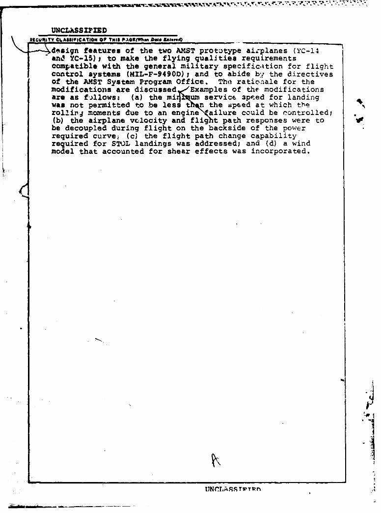
- d.tsign features of the two AZST prototype airplanes (YC-14and YC-15)i to make the flying qualities requirementscompatible with the general military specificaition for flightcontrol systems (MIL-F-9490D); and to abide by the directivesof the AMST System Program Office. The rationale for themodifications are discussed ,Examples of the modificationsare as fillows: (a) the mi um service 3pteed for landingwas not permitted to be less t?n the speed at which therollirP moments due to an engine ailure could be controlled;(b) the airplane velocity and flight path responses were to Vbe decoupled during flight on the backside of the powerrequired curve, (c) the flight path change capabilityrequired for STOL landings was addressed; and (d) a windmodel that accounted for shear effects was incorporated.
*1

FOREWORD
This report presents the USAF flying qualities require-ments for the Advanced Medium STOL Transport (AMST). Theserequirements were developed by. the Flight Systems Group, AMSTSystem Program Office, Aeronaatical Systems Division, Wright-Patterson Air Force Base, Oh'*o under project number 1226. Theproject engineer for th.-.s effort was Mr. Gary J. Gerken, andthe work was performed from May 1976 through March 1977.
This report was submitted by the author during December1978.
fccess ,n ForNT IS GR &IDTIC TA Elunanzo ned / 1JU:ti ict ti O
ByDi tri oan/
va abi ity Co~des
it, _ Y ....
Sc
|i|
, I I ' I ,r" , -.-.,.........-..+..::: +m + II " I ,'' I I ,11r
.ABLE OF CON=Ts
Page
SECTI 1 INThr1ocTION I
*1.1 Backtgrourx I
1.2 odIifioatio Procedure 2
SECTfIM 2 NWM ET CHANM AND PATIONALE 3
2.1 1.4 Flight PHase Categories 3
.2.2 2. Applicable Documents 4
2.3 3.1.6.2 Airplane Failure States 4
2.4 3.1.7 qCeraticnal Flight Envelopes 5
2.5 3.1.7.2 Min mn Operational Speed 5
2.6 3.1.7.4 Operational Load Factor 7
2.7 3.1.8.1 Maximum Service Speed 7
2.8 3.1.8.2 Minimn Service Speed 8
2.9 3.1.8.4 Service Load Factor 9
2.10 3.1.9.1 Maxum Pemissibl, Speed 10
2.11 3.1.9.2 Minbr-nm Peridssible Speed (Vs) 10
2.12 3.1.10.2 Requiremnts for Airplane Failure States 12
2.13 3.1.10.2.1 Requirremnts for Specific Failures 15
2.14 3.1.10.3.2 Wien Levels Are Not Specified 16
2.15 3.1.12 Assault Mode of Operation 17
2.16 3.2 Longitudinal Flying Oialities 17
- 2.17 3.2.1.1 Iongitudinal States Stability 17
2.18 3.2.1.2 Phugoid Stability 18
2.19 3.2.1.3 Hands On Flight - Path Stability 18
2.20 3.2.1.3.1 Hands Off Flight - Path Stability 20
2.21 3.2.1.4 Pitch Attitude Versus Flight Path Angle 20
V
Vt * -- -. ~ * A.. - - - -. - -- ~ *.- ,*- ~ - ' * - ~ j .rs" .b'..'.. ' * *4*-. -
I'I %
TABLE OF CONTENTS (CONTINUED) Page
2.22 3.2.1.5 Velocity hag-. Versus FlightPath Angle 21
2.23 3.2.2.1 longitudinal Response 21
2.24 3.2.2.1.1 Shoc-Term Frequency andAcceleration Sensitivity ,
2.25 3.2.2.1.; Total System Deuping -6
2.26 3.2.2.1.3 Ruidual Oscillations 26 13;
2.27 3.2.2A.4 Flight Path muponse 28
2.28 3.2.2.2 COmtrol Feel and Stabilit"in Maneuvering Flight 28
2.29 3.2.2.2.1 Ontzl Forces in Maneuvering Flight 29
2.30 3.2.3.2 Irgiitudinal Control in 31Maneuvering Flight 31
2.31 3.2.3.2.1 Flight Path Angle CmngeCapability P ayired for Landing onTactical Mobility Mission Runway (Paragraph3.2.1.1 of the System Specification) 32
2.32 3.2.3.2.1.a Landing in Turbulence 34
2.33 3.2.3.2.2 Turn Rate 35
2$34 3.2,3.3 Icngitudinal O(rtrol in Takeoff 35
2.35 3.2.3.4 longitudinal C'.atrol in Landing 36
2.36 3.2.3.4.2 Londing Control Power 36
2.37 3.2.3.4.3 Pitch Acceleration 36
2.38 3.2.3.5 Longitudinal Control Forces in Dives-
Service Flight Envelope 37
2.39 3.2.4 Pitch Attitude Omlnand 37
2.40 3.2.5 Airspeed arnand and Hold Modes 38
2.41 3.2.6 Pitch Rate Oommnid Mode 38
2.42 3.2.7 Pitch Hold Mode 39
2.43 3.3.1 Lateral-Directional MndeCharacteristics 40
2.44 3.3.1.2 Roll Mode 40
- .. . . . . . . .* .. *1*' : -; , : :; # ., " "¥,;:? i< g.,;";--;',--:-;',"-".'-,;-'?,-....-'-.. :..'-,-" -.-..... ...
.... k . . L ,, . : : . . k .i , * • .. ' L . 1' rL A ;a- -" iwu -" w -w 'w .
TABL- OF CONTENTS (CONTINUED) Page
2.45 3.l.1.3 Spxal Stability 42
2.46 3.3.1.4 Coupled oll-Spiral Oscillation 42
2.47 3.3.2.2 Roll Pate (scillaticr 42
2.48 3.3.2.2.1 Additional Roll ateRaufrements for Sm~all Ixrmts 43
2.49 3.3.2.4.1 Aditional Sideslip Requirementsfor small Lyputs 43
2.50 3.3.2.5.1 Lateral Acceleration Limits, Rolling 43
2.51 3.3.2.6 T1urn Cordination 44
2.52 3.3.2.7 Pasidual Oscillations 44
2.53 3.3.4 Roll Control Effectiveness 44
2.54 3.3.4.3 Linearity cf Poll Pasponse 46
2.55 3.3.4.5 Pu~der-Padal Induced Rolls 46
2.56 3.3.5.3 Yaw Ctrol 46
2.57 3.3.5.4 Yaw otrol Linearity and Sensitivity 47
2.58 3.3.5.5 Heading ontrol 47
2.59 3.3.6 Lateral-Directional Characteristicsin Steady Sideslips 47
2.60 3.3.6.3 Polling Moments in Steady Sideslips 48
2.61 3.3.7 Lateral Directional Cotyol in Croswinds 48
2.62 3.3.7.1 Final Approach in Crosswbids 49
2.63 3.3.9.1 Thrust Toss During Takeoff Run i.9
2.64 3.3.9.2 Thrust Loss After Takeoff 502.65 3.3.10 Roll Attitude Comn 512.66 3.4.1 Dangerous Flight Conditions 52
2.67 3.4.2.1 Stalls 52
2.68 3.4.2.1.1 Stall Approach 52
2.69 3.4.2.1.2 Stall Characteristics 53
2.70 3.4.2.1.3 Stall Prevention and Recovery 54
vii
TABLE OF CONTENTS (CONTINUED) Page
2.71 3.4.2.2.2 Remery fram Post-StallGyrations and Spins 54
2.72 3.5 Characteristics of the Manual FlightOantrol System (*CS) 54
2.73 3.5.2.1 Control Cantering and Breakout Forces 55
2.74 3.5.2.3 Rate of Cmtrol Displacement 56
2.75 3.5.3 Dynamic Characteristics 56
2.76 3.5.3.2 Danping 57
2.77 3.5.4.1 Perfornance of Augmentation Systens 57
2.78 3.5.4.2 Saturation of Augmentation Systems 57
2.79 3.5.5 Failures 58
2.80 3.5.5.1 Failure Transients 58
2.81 3.5.6.1 Transients 59
2.82 3.6.3.1 Pitch Trim Changes 59
2.83 3.6.5 Delete 63
II! 2.84 3.7 Atmospheric Brnvirvet 63
SE,'Ea4I 3 oJsIa4 A524IaNS 5
IAJPPENDIX 67
REENE;152
W,,
LIST OF SYMBOLS
SYMBOL DEFINITION UNITS
AEO All Engines Operating ---
AFFDL Air Force Flight Dynamics Laboratory ---
AFFTC Air Force Flight Test Center ---
AMST Advanced Medium STOL Transport ---
ARC Ames Research Center ---
B-i Bomber Aircraft ---
cMean Aerodynamic Chord ft
CEI Critical Engine Inoperative ---
cg Center of gravity (% of 1--
CTOL Conventional Takeoff and Landing ---
C-lXA Generalized Designation for AMST ---
DLC Direct Lift Control ---
ENFTC Flight Stability and Control Branch ---
FCS Flight Control System
Fs Stick Force
g Acceleration of gravity ft/sec 2
MAC Military Airlift Comman. ---
n Load Factor ---
SP6 System Program Office ---
SST Supersonic Transport ---
STOL Short Takeoff and Landing ---
T Thrust lb
u Perturbation velocity kts
USAF United States Air Force ---
ix

LIST OF SYMBOLS(continued)
SYMBOL DEFINITION UNITS
V Airspeed kts
Vs Stall Speed kts
GREEK CHARACTERS
Angle of Attack deg
B Sidaslip Angle deg
y Flight path angle deg
Indicates Change in Value ---
5* Control surface deflection angle deg I*a - elevator*Flap - flap deflection*a - control stick displacement*Slat - slat deflection
- pilot's control wheel
Damping ratio
6 Pitch attitude deg
o Damping (w) '/sec
TR Roll mode time constant sec
T Heading response time delay sec
* Bank angle deg,.-
*Heading angle deg
Frequency rad/sec
-. - -
i
SECTIO4) I
INTRODUCTION
1.1 ACKGROUND
The Advanced Medium STOL Transport (AMST) flying qualityrequirements are documented in this report, as well as therationale for them. These requirements were included In theProposal Instruction Package released on 16 September 1977,and were intended as requirements for a production AMST. Thegeneral requirements of the military specification, FlyingQualities of Piloted Airplanes (reference 1), were not directlyapplicable to the AMST and required modification. One reasonfor this was that the AMST was designed to fly frequently onthe back side of the power required curve at a lower dynamicpressure (q-25 lb/ftz) than conventional airplanes. The general Irequirements of Reference 1 were also modified to address thespecific design approaches taken by the two AMST prototype con-tractors, McDonnell Douglas Corporation (YC-15) and the BoeingAerospace Company (YC-14). Prototype flight test furtherdetermined areas of conflict with Reference 1, such that wherethe flight test results were acceptable, the general specifi-cation requirements were modified. Requirements and termin-ology of Reference 1 were also changed to be compatible withthe military specification for Flight Control Systems (Refer-ence 2). Procuring activity management direction also resulted
in changes to the general requirements of Reference 1. Thesedirectives were as follows:
a. A specification states the required system performance;not design solutions.
b. Procuring activity approval of a design approach waseliminated in order to give the contri cor design flexibilityto meet the required performance.
c. Tiering of specifications was prohibited. That is, aspecification could not be invoked simply by referencing it inanother. The intent of this requirement was to prevent needlesSIcoiitradictory or redundant requirements for the AMST. Require-ments could be extracted from any specification or an entirespecification used if it were applicable to the AMST.
*
d. The contractor was required to prepare a detailedQuality Assurance section for each specification; therefore, nodetailed guidance was given the contractors on how each require-ment of a specification was to be verified.
The decision was made early in the development of the AMST
. w : , , T, -< .- : . . . -..-..- . -. -. .- .;-'. - ..' .-- -." . -%'. i-..- '% 1 ' '-.' '.
.. flying qualities requirements to mod f;, Reference 1 for both
conventional and STOL flight. The military specification,Flying Qualities of Piloted V/STOL Aircraft (Reference 3),did not adequately address STOL flying qualities and was moreepplicable to VTOL than STOL airplanes. The modification ofReference 1 to address STOL was not as complex as it may seem.Many of the same considerations are present for both conven- Itiorial and STOL flight, such as flight envelopes, failurestates, and flight control system response characteristics.Where specific STOL requirements were needed, they were statedin an appropriate section of Reference 1 either by incorporatinginto an existing requirement or by adding a new paragraph number.During the modification of Reference 1, the original paragraphnumbers and subjects remained unchanged to allow easy comparisonbetween the AMST requirements and the general specification.Note that in the AMST specification the acronym STOL was notuced due to the lack of a universal definition. STOL has beendefined in the past in terms of airspeed, dynamic pressure, per-cent powered lift, field length, approach flight path angle,etc., but no universal agreement on a definition .has beenreached.1.2 MODIFICATION PROCEDURE
The Aeronautical Systems Division, specifically the AMSTFlight Systems Group and the Flight Stability and Control Branch(ENFTC) had the responsibility to define the USAF flying qualityrequiremr-cs for the AMST. A review was first conducted ofSTOL simulation reports, analytical studies, limited flightexperience and proposed STOL flying quality criteria. Based onthis information, a general understanding of STOL flyingqualities was obtained, particularly in areas that differedgreatly from conventional flight characteristics. Reference 1was then reviewed to determine if the requirements were adequate,needed to be revised, or if a new requirement had to be addedto account for STOL characteristics. Five draft specificationswere prepared between May 1976 and March 1977. Comments on thesedraft versions were obtained from the AMST contractors, theAir Force Flight Dynamics Laboratory (AFFDL), the NASA AmesResearc4 Center, and the Air Force Flight Test Center (AFFTC).Coordination was also performed in-house to ensure that flightcontrol, performance, structures and other personnel wereprovided an oppotunity to comment on requirements which affectedtheir disciplines. The various drafts were revised based on thecomnenrs received until t a final AMST flying quality require-ments were released on 11 September 1977. A copy of theserequirements is presented in the appendix.
The next section of this report will present the major AMSTrequirements changes from Reference !. and the rationale for thechanges. "Section 3 presents the conclusions and recommendationsresulting from the preparation of AMST flying qualities require-ments.
-~ ~4 ~*~..*** *.&. . ~ ' 4 '. * .'CAL
SECTION 2
REQUIREMENTS CHANGES AND RATIONALE
This section presents the major AMST requirements changesfrom the general military specification, Flying Qualities ofPiloted Airplanes (Reference 1). Complete AMST requirementsincluding paragraph r-mbers, titles and wording, are presentedbelow and are followed by a discussion of the rationale forthe requirements. Only the final versions of the AMSTrequirements are presented below, and no effort was made tof6ollow the eVoiution of the requirements through the five drafts...Note that the symbol C-lXA was used to denote the AMST for pro-posal instruction purposes, and is used in the requirements below.
2.1 3.4 Flight Phase Categories. The Flight Phases have beencombined into three categories which are referred to in ther~quirements statements. These Flight Phases shall be consideredin the context of total missions so that there will be no gapbetween successive Phases of any flight and so that transitionwill be smooth. In certain cases, requirements are directed atspecific Flight Phases identified in the requirement. When noFlight Phase or Category is stated in a requirement, that require-ment shall apply to all three categories. Flight Phasesdescriptive of the C-lXA are:
Nonterminal Flight Phases:
Category A - Those nonterminal Flight Phases that requirerapid maneuvering, precision tracking, or precise flight-path control. Included in this Category are:
a. Low Altitude Aerial Delivery (LA).Ib. Close Formation Flying (Fr).C. Contour Flying (CF).d. In-fli~ht Refueling (receiver) (RR).
Contour flying involves flight at altitudes up to 1000fet above ground level to avoid ground fire or detection.
Category B - Those nonterminal Flight Phases that arenormally accomplished using gradual maneuvers and withoutprecision tracking, although accurate flight-path controlmay be required. Included in this Categozy are:
a. Climb (CL) d. Descent (D)b. Cruise (CR) e. Deceleration (DElc. Loiter (LO) f. Aerial Delivery (AD)
3A
0
Terminal Flight Phases:
Category C - Terminal Flight Phases normally requiringaccurate flight path control.
a. Assault Takeoff (AT) d. Go-around (GA)b. Takeoff (TO) e. Assault Landing (AL) Ic. Approach (PA) f. Landing (L)
The word assault in this document is meant to signify that Iengine failed safety margins are not provided.
Discussion: This paragraph follows the general specifica- Ition cltsely althougheome explanation of the flight phases isneeded. For Category A, the Low Altitude Aerial Deliveryflight phase relates to the Low Altitude Parachute ExtractionSystem (LAPES) maneuver. The Category B flight phases of jDescent and Deceleration are also intended to account for Emer-gency Descent and Emergency Deceleration. For Category C, theTakeoff and Landing flight phases include STOL Takeoff and STOL PLanding. Assault Takeoff and Assault Landing are an effort todefine the maximum capability of a STOL airplane by not pro-viding engine out safety margins. The Assault Flight phases are
S.. considered to be a fallout of the design and probably would onlybe used under wartime situations. As implied above, variousairplane configurations can exist for a particular flight phase,and the cntractor must define these as requiied by paragzaph3.1.5, Configurations. N
2.2 2 Applicable Documents. Deleted.
Discussion: Applicable documents were deleted since pro-other specifications. The intent of this policy was to prevent
"blanket" application of a specification without a thoroughreview of its requirements. Appropriate requirements of thelisted specifications in the general MIL-F-87853 (Reference 1)could have been retained if desired after a review. However,it was concluded that appropriate AMST personnel associatedwith the listed specifications were to review their require-ments and no need was seen to duplicate their efforts. The %only exception to this was the specification Stall/Post-Stall/Spin Flight Test Demonstration Requirements for Airplanes,MIL-S-83691, which was reviewed. It was concluded that thegeneral MIL-F-8785B specification requirements were adequate,and that MIL-S-83691 would be used for guidance when it cametime for the procuring activity to approve the contractor pro-posed flight test conditions to be used for stall testing.
2.3 3.1.6.2 Airplane Failure States. The contractor shalldefine and tabulate all Airplane Failure States which consist
- r. ---- --.-- '.- : ~ -- - . - * i,
of failures of airplane components or systems that affectthe Flying Qualities of the airplane. Failure States causedby more than three independent subsystem failures need not betabulated. Airplane Failure States shall reflect changes inairplane hardware or the results of more detailed analyses.Examples would be jammed surfaces, mechanical or electricaldisconnects, one or more channels of augmentation failed, and/ortwo hydraulic systems out. Other !egradations or failure ofairplane components for systems resulting from the first failuremust also be accounted for in determining the total effects onaircraft control. More specific direction is given in 3.1.10.2.3.1.6.2.1 Airplane Special Failure States. Certain components,-ystn~s, -or, COMbinations thereof may have extreeyrmtprobabilityof failure during a given mission. These failureprobabilities may, in turn, be very difficult to predict with anydegree of accuracy. Special Failure States of this type neednot be considered in complying with the requirements of Section 3(except 3.1.10.2) if justification for considering the FailureStates as special is submitted by the contractor. The AirplaneSpecial Failure States shall reflect changes in airplane hardwareor the results of more detailed analyses. Failures which have aprobability of occurrence less than ixl0 "9 per mission may beconsidered Special Failure States without submittal to the pro-curing activity.
Discussion: The wording changes for these paragraphs wereto clarify what failures were to be defined and to limit theamount of paperwork required by the contractor. The paperworkwas reduced by limiting the failures to be tabulated and submittedto those caused by three independent subsystem failures and bydefining a special failuire state as one having a probability of
failure less than ixl0 -9 per mission.
2.4 3.1.7 Operational Flight Envelopes. The OperationalFlight Envelopes define the boundaiiesiTn terms of speed,altitude, and load factor within whicb the airplane must becapable of operating in order to accoi,;Lish the missions of 3.1.1.These envelopes shall be defined for the atmospheric .tempera-tures required by paragraph 3.2 of the System Specification andAppendix 50 of the System Specification. Envelopes for eachapplicable Flight Phase shall be established by the contractor.The boundaries of the Operational Flight Envelopes shall be asdefined by paragraphs 3.1.7.1, 3.1.7.2, 3.1.7.3, and 3.1.7.4.
Discussion: The above paragraph was changed to require thatthe envelopes be defined for standard and hot day temperatures.This was significant since STOL stall speeds depend heavily onthrust available, and thrust available is dependent upon tempera-ture. Paragraphs 3.1.8 Service Flight Envelopes and 3.1.9 Per-missible Flight Envelopes were modified similarly.
2." 3.1.7.2 Minimum Operational Speed. The minimum operational
5
g - h r r r . ....-
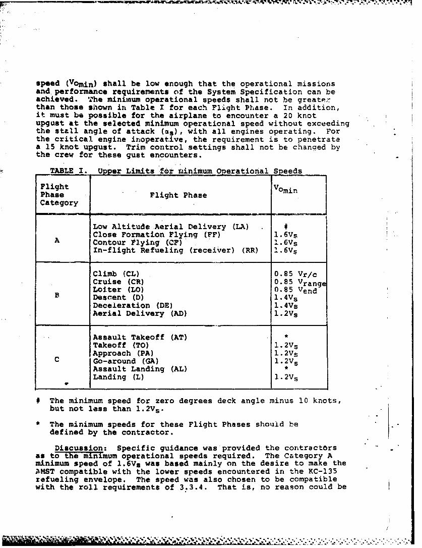
speed (Vomin) shall be low enough that the operational missionsand performance requirements of the System Specification can beachieved. The minimum operational speeds shall not be greaterthan those shown in Table I for each Flight Phase. In addition,it must be possible for the airplane to encounter a 20 knotupgust at the selected minimum operational speed without exceedingthe stall angle of attack (as), with all engines operating. Forthe critical engine inoperative, the requirement is to penetratea 15 knot upgust. Trim control settings shall not be changed bythe crew for these gust encounters.
TABLE 1. Upper Limits for rinimum Operational Speeds
Flight VominPhase Flight PhaseCategory
Low Altitude Aerial Delivery (LA) #Close Formation Flying (FF) 1.6Vs
A Contour Flying (CF) 1.6Vs
In-flight Refueling (receiver) (RR) 1.6V s
Climb (CL) 0.85 Vr/cCruise (CR) 0.85 VrangeLoiter (LO) 0.85 Vend
B Descent (D) 1.4V sDeceleration (DE) 1.4VsAerial Delivery (AD) 1.2Vs
Assault Takeoff (AT) *Takeoff (TO) 1.2V sApproach (PA) 1.2Vs
C Go-around (GA) 1.2V sAssault Landing (AL) *Landing (L) 1.2V s
# The minimum speed for zero degrees deck angle minus 10 knots,but not less than 1.2V s .
* The minimum speeds for these Flight Phases should bedefined by the contractor.
Discussion: Specific guidance was provided the contractorsas to the minimum operational speeds required. The Category Aminimum speed of 1.6Vs was based mainly on the desire to make theAMST compatible with the lower speeds encountered in the KC-135refueling envelope. The speed was also chosen to be compatiblewith the roll requirements of 3.3.4. That is, no reason could be

determined for having the minimum operational speed lowerthan 1.bVs, and the 1.6Vs speod made the roll requirementsreasonably obtainable.
Tho gust encounter requirements were based on Reference 3,and the intent was to provide the STO airplane with the capa-bility to penetrate the same gusts usually encountered byconventional airplanes. Since the STOL airplane approaches ata lower airspeed than a conventional airplane, the angle ofattack margin to stall must be larger than that nc-rmally pro-vided. The gust magnitude was reduced with an engine failurebecause the probability cof having an engine failure andencountering the higher gust was considered small. Thus, thegust magnitude was reduced to make it a more reasonable prob-ability of occurrence.
2.6 3.1.7.4 Operational Load Factors. The maximum (minimum)operational load factor is the lowest (highest) algebraicallyof the following:
a. n - 2.0 (n a 0.5).
b. The load factor at which stall warning occurs.
The maximum and minimum operational load factors for each FlightPhase shall be established as a function of speed for severaldifferent altitudes.
Discussion: The operational load factor limits wereselected based on what were considered to be required for theoperational missions. Load factor limits higher than thoseselected were discussed but design penalties were probable atthe limits of the airspeed-load factor (V-g) envelopes. Thepenalties mentioned most often were a complex stick force versuselevator deflection gearing to meet the stick force per glinearity requirement, and sizing the noll control surfaces tomeet the roll requirements.
2.7 3.1.8.1 Maximum Service Speed. The maximum service speed,Vmax O& Mmax, for each altitude stall be the same as the maximumoperational speed. An acceptable speed margin shall existbetween the maximum service speed and the maximum permissiblespeed, with the, highlift devices stored, to allow for inadvertentoverspeed conditions. When the high-lift devices are extended,the maximum service speed may be the same as the maximum permis-sible speed.
Discussion: In general, the AMST prototype maximum speeTswere defined arbitrarily by the contractors with only the cruiseMach number and altitude defined by the procuring activity. Thecontractors added an arbitrary incremental Mach number to thecruise Mach number, which then defined the constant altitude
7
maximum speed (VH). It was intended by the above requirementthat both the operational and service maximum speeds be VH.The thrust required to attain yR was less than that availablein many cases and thus VH could be exceeded at constant altitudeby adding power. The contractors added an overspeed margin toVH that resa.lted in a limit speed (VL). The maximum permissiblespeed was intended to be VL. It was felt that the margin foroverspeed conditions should be 0.05 Mach or the increase inspeed obtained during a 7.5 degreos dive held for 20 secondsand then recovered at l.5g's, whichever is greater. Thelatter requirement was based on FAR Part 25, Section 25.335(b) (1).These were not specified in 3.1.8.1 due to an incomplete under-standing of the impact they would have on the separate contractors.The two definitions are considered reasonable for defining theoverspeed margin. For the high-lift devices extended case, nogpeed maF~Rgin Wa! equired since the FAA does not require amargin nor could the need for 'one "be established. Refer to FARIPart 25, Section 25.333.
The above requirement differs from the general MIL-F-8785B(Reference 1) in that the general specification would allow theImaximum service speed to be the same as the maximum permissiblespeed. This was not considered safe, and it was required thAtan acceptable speed margin be provided as stated above. TheIgeneral MIL-F-8785S. part "c", may have required a 'speedmargin,but the intent of that part of the requirement was not clear.
2.8 3.1.9.2 MnmmService Speed. The minimum service speed,
Vmin or Mmn for ea atitude is the highest of:
a. l.1V5
b. VS + 10 knots equivalent airspeed.
1
c. Stall warning speed defined by 3.4.2.1.1, for anythrust setting'.
d. A speed at which it is possible to achieve a constantheading following a sudden asymmetric loss of takeoff thrust fromthe most critical factor, and thereafter to maintain a constantheading. No changes in the pilot selected configuration areallowed to show compliance with this requirement. In addition,at this speed, the roll control capability shall provide at least -
30 degrees bank angle change in four seconds. Th--e roll require-muent shall be met for the steady state asymmetric thrustcondition with takeoff thrust maintained on the operative engine(s)and trim at normal settings for symmetric thrust. The airplanemay be banked up to five degrees in a direction to assist control.
e. A speed limited by reduced visibility or an extremepitch attitude that would result in the tail or aft fuselagecontacting the ground.
*.- 2t. .tq. -. - a * ~ . . .
I
Discussion: The AMST minimum service speed definitiondiffers in for major respects with the general MIL-F-8785B(Reference 1). First, the MIL-F-87e5B, part c, was deleted.Part c allowed a minimum speed where full airplane nose upelevator control power and trim were required to maintainstraight, steady fliqht. NASA Ames Research Center statedthat this condition was more appropriate to a PermissibleEnvelope limit, and AMST pezsonnel concurred. Second, part dof MIL-F-8785B, which defined the minimum speed as that at whichlevel flight could be maintained with Military Rated Thrust, wasdeleted. The reason for this was that an airplane in the STOLlanding configuration may not have sufficient thrust to flylevel, and no justification could be determined for requiringthat it fly level. Third, para c of the AMST requirement doesnot allow the minimum service speed to be less than the speedat which stall warning occurs for either unaccelerated oraccelerated stalls. This was an addition and the intent was toprohibit stall warning within the Service Flight Envelope.Lastly, a minimum air control speed requirement was added to !ensure that the STOL airplane on landing would have sufficientlateral control with an engine failed. For the STOL airplane,an engine failure results in a large lift loss which inducesa large rolling moment which must be controlled. The rollcontrol capability of 30 degrees bank angle change in four
seconds was required to provide the capability to control thedynamics of the engine failure, ahd then after the failure anyroll upsets due to turbulence or winds. This roll capabilitywas intended to be demonstrated both into and away from thefailed engine.
2.9 3.1.8.4 Service Load Factors. Maximum and minimum serviceload factors, n(+) [n(-)], shall be established as a functionof speed for several significant altitudes and weights. Noconsideration is given to the power required to maintain flightat these g levels. The maximum (minimum) service load factor,when trimmed for ig flight at a particular speed and altitude,is the lowest (highest) algebraically oZ:
a. The positive structural limit load factor, or for negativeload factor to zero g's.
b. The load factor corresponding to stall warning (3.4.2.1.1).
c. A safe margin below (above) the load factor at whichintolerable buffet or structural vibration is encountered.
Discussion: The second sentence above was added with theintent to clarify that 3.1.8.4 was addressing instantaneous loadfactor capability and not sustained load factor. Sustained loadfactor would necessitate an increase in thrust in order to hold
9
p
airspeed, altitude and load factor. Part a of the AMSTrequirement limits the negative load factor to zero g's.This was considered adequate for mission flexibility andreduced flight test verification of requirements since theservice envelope was reduced. Part c of the general MIL-F-8785B(Reference 1) was deleted for the reason stated in 2.8 forpart c.
2.10 3.1.9.1 Maximum Permissible Speed. The maximum permissiblespeed for each altitude shall be the lowest:
a. Limit speed based on structural considerations.
b. Limit speed based on engine considerations.4
c. The speed at which intolerable buffet or structuralvibrations is encountered.
d. The speed at which tha transonic Mach tuck is greaterthan allowed for Level 3 of paragraph 3.2.1.1.1.
Discussion: Two differences exist between the above .-equire-mert and the general MIL-F-8785B (Reference 1). The intert and Nmeaning of part d of the general MIL-F-8785B requirement were notclear; therefore, it was deleted. Part d of the above AMSTrequirement allows the permissible envelope to be limited byMach tuck. This was added so that adequate flyingqualities would not have to be provided out to the structuralairplane limits, since there were no operationil or safetyconsiderations to do so. As discussed in 2.7, the maximum per-missible speed was intended to be the limit speed, VL, whichaccounted for overspeed conditions from the maximum servicespeed.
2.11 3.1.9.2 Minimum Permissible Speed(V). The minimumpermissible speed for a specifed configuration shall be thehighest of:
a. Speed with constant heading angle for flight at CLmax(the first local maximum of the lift coefficient vs angle ofattack which occurs as CL is increased from zero),
b. Speed at which uncontrollable pitching, rolling, or yawingoccurs; i.e., loss of control about a single axis.
c. Minimum demonstrated Rpeed due to intolerable buffet,structural vibration, angle of attack effects, or an excessive'rate of sink.
The minimum permissible speed shall be determined for:
a. lg normal to the flight path.
. .. . . , ,.
b. Approach to stall at 1/2 knot to 1 knot per second.
c. Most unfavorable center of gravity.
d. Out of ground effect.
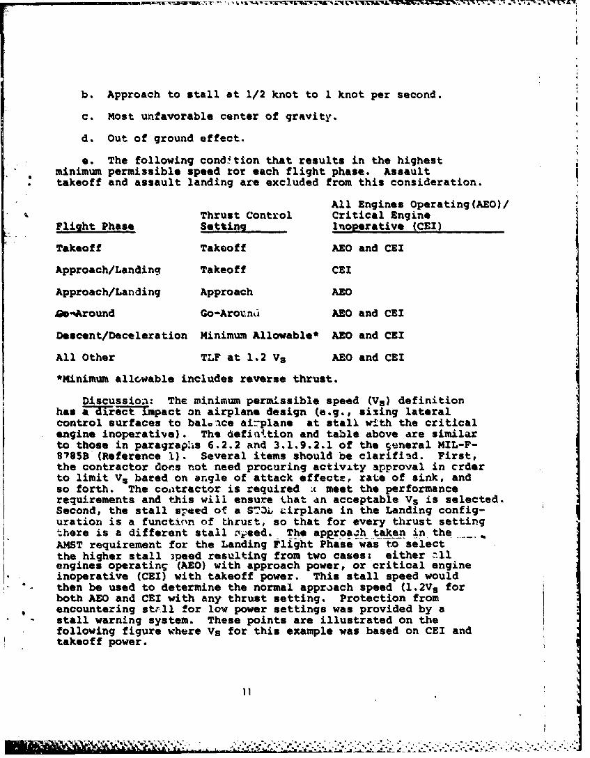
e. The following cond'tion that results in the highestminimum permissible speed tor each flight phase. Assaulttakeoff and assault landing are excluded from this consideration.
All Engines Operating(AEO)/Thrust Control Critical Engine
Flight Phase Setting Inoperative (CEI)
Takeoff Takeoff AEO and CEI
Approach/Landing Takeoff CEI
Approach/Landing Approach AEO
a-oAround Go-Arovn AEO and CEI
Descent/Deceleration Minimum Allowable* AEO and CEI
All Other TLF at 1.2 Vs AEO and CEI
*Minimum allowable includes reverse thrust.
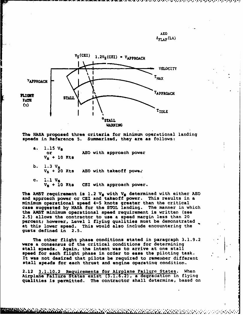
Discussioa: The minimum permissible speed (Vs) definitionhas a diect Impact on airplane design (e.g., sizing lateralcontrol surfaces to balaace airplane at stall with the criticalengine inoperative). The 6efiattion and table above are similarto those in paragraphs 6.2.2 and 3.1.9.2.1 of the Seneral MIL-F-8785B (Reference L). Several items should be clarified. First,the contractor Coes not need procuring activity approval in crderto limit Vs bated on angle of attack effecte, rate of sink, andso forth. The contractor is required t meet the performancerequ.rements and this will ensure that an acceptable Vs is selected.Second, the stall speed of a ST3L cirplane in the Landing config-uration is a function of thrust, so that for every thrust settingthere is a different stall yeed. The apprpa. h taken in theAMST requirement for the Landing Flight Phase was to selectthe higher stall gpeed resulting from two cases: either -11engines operating (AEO) with approach power, or critical engineinoperative (CEI) with takeoff power. This stall speed wouldthen be used to determine the normal approach speed (1.2Vs forboth AEO and CEI with any thrust setting. Protection fromencountering str.ll for low power settings was provided by astall warning system. These points are illustrated on thefollowing figure where Vs for this example was based on CEI andtakeoff power.
1" ' . .. ., ., ..- .... . . , .. . .. .. .. . ........ ..
AEO8FLAP (LA)
Vs(CEI) 1.2Vs(CEI) - VAPPROACH
VELOCITY
"APPROAC
p | TIDLE
aSTALLWARNING
The NASA proposed three criteria for minimum operational landingspeeds in Reference S. Summarized, they are as follows:
a. 1.15 Vsor AEO with approach power
Vs + 10 Kts
b. 1.3 VsVS + 20 Kts AEO with takeoff powez
C. 111 VsV5 + 10 Kts CEI with approach power.
The AMST requirement is 1.2 Vs with Vs determined with either AEOand approach power or CEI and takeoff power. This results in aminimum operational speed 4-5 knots greater than the criticalcase suggested by NASA for the STOL landing. The manner in whichthe AMST minimum operational speed requirement is written (see2.5) allows the contractor to use a speed margin less than 20percent; however, Level 1 flying qualities must be demonstratedat this lower speed. This would also include encountering thegusts defined in 2.5.
The other flight phase conditions stated in paragraph 3.1.9.2were a consensus of the critical conditions for determiningstall speeds. Again, the intent was to arrive at one stallspeed for each flight phase in order to ease the piloting task.It was not desired that pilots be required to remeber differentstall speads for each thrust and engine operatinq condition.
2.12 3.1.10.2 Requirements for Airplane Failure States. WhenAirplane Failure States exist (3.1.6.2), a degradation in flyingqualities is permitted. The contractor shall determine, based on
the most accurate available data, the probability of occurrenceof each Airplane Failure State per mission and the effect of the?ailure State on the flying qualities within the Operationaland Service Envelope. Specifically, the analysis shall addressthe followingi (a) The Wartime - Logistics Resupply - AirlandProfile defined in the System Specification, Appendix 60, par&-graph 4.3, Table 60.4 shall be used for this analysis. Thismission scenario will be used to determine how long specificaircraft systems are used per mission. (b) All of the variouselements that can fail in many different modes but result in thesame general airplane condition shall be tabulated under onegeneral failure state (e.g., pitch augmentation failure, forcegradient reduction, one hydraulic system out, etc.). Theprobability of encountering the general failure state shall becalculated as a function of all the element failures. Once theeffect of a general failure state on handling qualities isdetermined (See part c), the probability of encountering aparticular level of handling qualities is also known for aparticular general failure state. (c) The effect of a generalfailure state on handling qualities in calm air must bi deter-mined by either analytical comparison of the degraded perform-ance with quantitative requiremnts stated herein or pilotopinion from simulation studies investigating a particularfailure(s). (d) The probability per mission of encounteringLevel 2 shall include the probability of all the general failurestates in which the Flying Qualities are worse than Level 2.(e) The probability per mission of encountering Level 3 shallinclude the probability of all the general failure states inwhich the Flying Qualities are worse than Level 3 and are unsafe.
(f) The probability of encountering Flying Qualities Levels 2 or3 shall include the special failure states, if the probabilitycan be calculated. (g) Each general failure state is assumedto be present at whichever point in the flight envelope that ismost critical from a handling qualities point of view. (h) Randomfailures which result in Level 3 or below flying qualities atthe altitudes and airspeeds of the missions of System Specifica-tion, Appendix 60, shall be assumed to .esult in mission abort.These aborts shall be included in the C-lXA mission reliability
hanalysis. (i) Encountering below Level 3 flying qualities willbe assumed to be a safety consideration and shall be includedin the C-lXA mission safety analysis.
The probabilities of encountering lower levels of flyingqualities due to failures shall be less than the values shownin Table III.
13
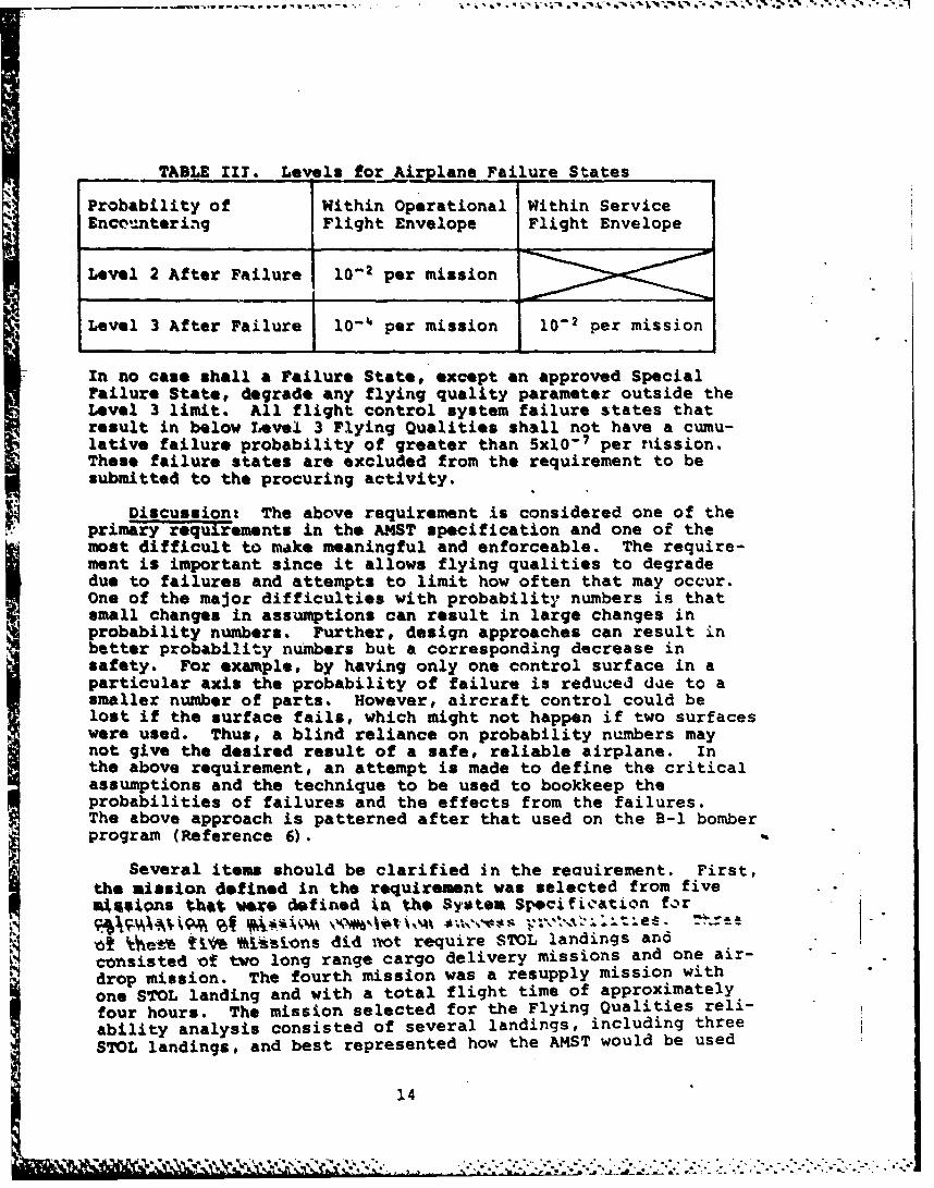
. . TABLE II1. Levels for Airplane Failure States
Probability of Within Operational Within ServiceEnc,-ntering Flight Envelope Flight Envelope
Level 2 After Failure 10-2 per mission
Level 3 After Failure j0- per mission 10-2 per mission
In no case shall a Failure State, except an approved SpecialFailure State, degrade any flying quality parameter outside theLevel 3 limit. All flight control system failure states thatresult in below Level 3 Flying Qualities shall not have a cumu-lative failure probability of greater than 5x10 -7 per riission.These failure states are excluded from the requirement to besubmitted to the procuring activity.
Discussion: The above requirement is considered one of theprimary requirements in the ANST specification and one of themost difficult to make meaningful and enforceable. The require-ment is important since it allows flying qualities to degradedue to failures and attempts to limit how often that may occur.One of the major difficulties with probability numbers is thatsmall changes in assumptions can result in large changes inprobability numbers. Further, design approaches can result inbetter probability numbers but a corresponding decrease insafety. For example, by having only one control surface in aparticular axis the probability of failure is reduced due to asmaller number of parts. However, aircraft control could belost if the surface fails, which might not happen if two surfaceswere used. Thus, a blind reliance on probability numbers maynot give the desired result of a safe, reliable airplane. Inthe above requirement, an attempt is made to define the criticalassumptions and the technique to be used to bookkeep theprobabilities of failures and the effects from the failures.The above approach is patterned after that used on the B-i bomberprogram (Reference 6).
Several items should be clarified in the reauirement. First,the mission defined in the requirement was selected from fives Qfls thot war* defined iA the Systeu Spcifiation fir
Se*% %ijons did ivot require STOL landings andconsisted of two long range cargo delivery missions and one air-drop mission. The fourth mission was a resupply mission withone STOL landing and with a total flight time of approximatelyfour hours. The mission selected for the Flying Qualities reli-ability analysis consisted of several landings, including threeSTOL landings, and best represented how the AMST would be used
14
a a .I " .- m A
in a war environment. The total flight time for the selectedmission was approximately 10 hours. This mission time willmake it difficult to meet the probability numbers of Table IIIsince those numbers were based on a four hour mission time(Reference 14, page 45). This is illustrated by the followingexample. Assume that the mean time between failures that causea degradation to Level 2 Flying Qualities is 500 flight hours.Thus, the probabilities of encountering Level 2 for a four hourand a ten hour mission are as follows: -
4 hours: P - l-e4/500a .0080
10 hours: P - l-a-O/SO0 - .0198. .
Second, compliance with the requirement was intended to be shownanalytically in calm air. Extending the requirement to accountfOr turbulent air was felt to be beyond the meaningful accuracylevel of the analysis. Third, part h of the requirement was anattempt to relate a flying qualities Level 3 to a mission abort.The intent of part h was to evaluate random failures thatoccur during analytical mission reliability-studies in termsof flying qualities. Missions would be aborted and tabulatedas such if Level 3 flying qualities result at the point of thefailure or at some other critical Mach/altitude point in theremainder of the mission. This differed from how the contractorwould show compliance with the probability numbers of i1. Ill.For Table 1fI, the contractor would investigate *,.e worst efectof a failure throughout the entire Operatione -nvelope and LhcService envelope, respectively. The reason this was not donefor the mission reliability analysis was that it was consideredoverly stringent and would have had an unrealiLH.c impact onmission reliability. Fourth, it was required that the probabilityof encountering Level 2 include the probability of encounteringLevels of Flying Qualities worse than Level 2. A similar require-ment was added for determining the probability of encounteringLevel 3. The reason for this method of calculation is that intheory an airplane state must pass tarcugh a better airplanestate (e.g., Level 2) to get to a worse state (e.g., Level 3).In practice, this method of calculation does not change theprobability numbers greatly since the probability of encounteringa worse state (e.g., Level 3) is usually small compared to theprobability of encountering the better state (e.g., Level 2).Lastly, a statement was added below Table III that all flightcontrol system failure states that result in below Level 3Flying Qualities shall not have a cumulative failura probabilityof greater than 5x0-7 per mission. This requirement was arestatement of one in the military spacification for Flight Con-
" . trol Systems (Reference 2), paragraph 3.1.7. It was restatedabove to define failures that were not required to be submittedto the procuring activity in order to reduce paperwork.
15
'\ " "* : v v , , .. . .,.. . . . . - - . . .. ,"
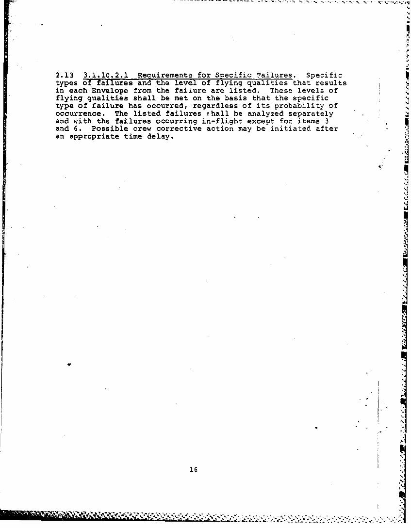
2.13 3.1.10.2.1 Requirements for Specific Failures. Specifictypes of failures and the level of flying qualities that resultsin each Envelope from the faiiure are listed. These levels offlying qualities shall be met on the basis that the specifictype of failure has occurred, regardless of its probability ofoccurrence. The listed failures thall be analyzed separatelyand with the failures occurring in-flight except for items 3and 6. Possible crew corrective action may be initiated afteran appropriate time delay.
41
1I6
16 I
I'.
* *-- " Sde.*
16.-. - - - .
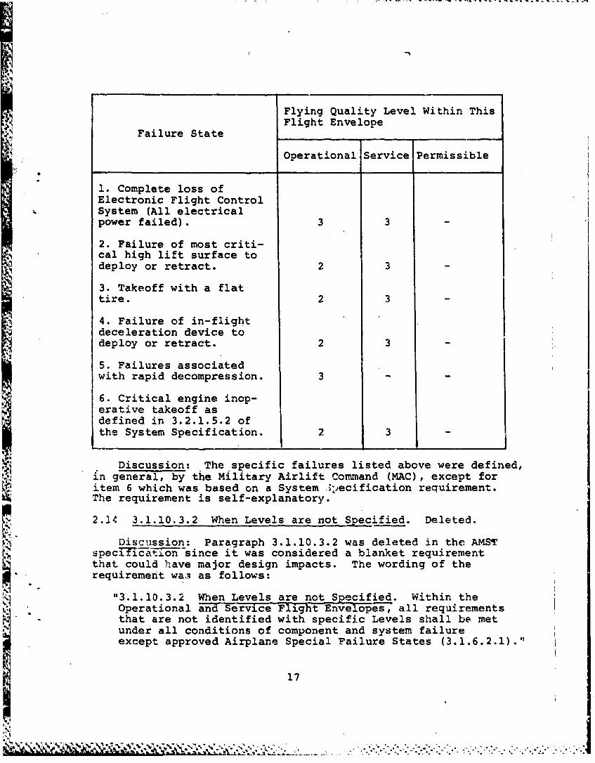
Flying Quality Level Within ThisFlight Envelope
Failure State
Operational Service Permissible
1. Complete loss ofElectronic Flight Control
*System (All electricalpower failed). 3 3
2. Failure of most criti-cal high lift surface todeploy or retract. 2 3
3. Takeoff with a flattire. 2 3
4. Failure of in-flightdeceleration device todeploy or retract. 2 3
5. Failures associatedwith rapid decompression. 3
6. Critical engine inop-erative takeoff asdefined in 3.2.1.5.2 ofthe System Specification. 2 3
Discussion: The specific failures listed above were defined,in general, by the Military Airlift Command (MAC), except for
item 6 which was based on a System .),ecification requirement.The requirement is self-explanatory.
2.14 3.1.10.3.2 When Levels are not Specified. Deleted.
Discuission: Paragraph 3.1.10.3.2 was deleted in the AMSTspecIT-Ic-to-since it was considered a blanket requirementthat could have major design impacts. The wording of therequirement wa,3 as follows:
"3.1.10.3.2 When Levels are not Specified. Within theOperational and Service Flight Envelopes, all requirementsthat are not identified with specific Levels shall be metunder all conditions of component and system failureexcept approved Airplane Special Failure States (3.1.6.2.1)."
17 ------------------------------------------------
For example, 3.1.10.3.2 could have resulted in paragraph3.3.9.1, "Thrust Loss During Takeoff Runs," requiring thatthe deviation of 30 feet from the runway centerline followingan engine failure be met with hydraulic systems out or with arudder hardover in a direction opposite to that required. Insteadof using 3.1.10.3.2, all the AMST flying qualities requirementswere reviewed and the required Levels defined where it wasconsidered to be appropriate.
2.15 3.1.12 Assault Mode of Operation. Maximum use of powerlift effects for airplane performance can be achieved byreducing the normal speed and control margins provided toaccount for failures. If this reduced margin region is utilized,a minimum of Level 2 handling qualities must be provided priorto failure occurrence.
Discussion: This requirement was added with theintent to allow the full capabilities of a STOL airplane to beused in a wartime environment. With reduced engine out controland speed margins, the STOL airplane could carry more weightinto or out of a STOL field than it was designed for or land atshorter fields at a reduced landing speed with the same weight.If the contractor defines an assault mode of operation, then aminimum of Level 2 flying qualities must be provided.
2.16 3.2 Longitudinal Flying Qualities. Two primary longitu-dinal controllers are allowed. A third controller may be usedif the pilot does not have to remove his hand(s) from the primarycontroller(s) to operate it. Contractor must define what primaryairplane response is expected from each controller. If theresponse varies with airspeed, flap angle, etc., this must bedefined.
Discussion: This requirement was based on NASA Ames ResearchCenter studies which found that the pilot workload becameunacceptable if three controllers were used continuously duringa STOL landing. A third controller might be used to commandflap angle or thrust vector. A controller such as a direct liftswitch on the throttle would be acceptable as long as the pilotwould not have to remove his hands from the throttles tooperate it.
2.17 3.2.1.1 Longitudinal Static Stability. There shall be notendency tor the airspeed to diverge aperiodically when the air-Plane is disturbed from trim due to external disturbances withthe cockpit controls fixed and with them free, except as allowedby 3.2.2.1.2. For alrplane states that includu automaticreduction of pilot control forces for steady state variations inspeed or load factors, stable or neutral elevator control forceand elevator control position with airspeed and load factor maybe.provided. The automatic reduction of forces shall not resultin any reversal of the pilot's control force (i.e., from push topull or vice versa).
18
For all other airplane states, this requirement will beconsidered satisfied if the variations of elevator controlforce and elevator control positior with airspeed are smoothand the local gradients stable with: Trimmer and throttlecontrols not moved from the trim settings by the crew and lgacceleration normal to the flight path and constant altitudeover a range about the trim speed of +15 percent or +50 knotsequivalent airspeed, whichever is less (except where-limitedby the boundaries of the Service Flight Envelope).
Stable gradients mean increasing pull forces and aft motionof the elevator control to maintain slower airspeeds and theopposite to maintain faster airspeeds. Neutral gradients meanzero pull forces and no motion of the elevator control to main-tain slower or faster airspeeds. The term gradient does notinclude that portion of the control force or control positionsversus airspeed curve within the preloaded breakout force orfriction range.
Discussion: This requirement was modified from the generalMIL-F-8785B (Reference 1)to address the control augmentationfeatures of the AMST prototypes. These features were found tobe acceptable based on prototype flight test experience. Onepart of the requirement is that the airspeed shall not divergeaperiodically due to external disturbances with or without anaugmentation system functioning. This was to ensure that theairspeed would not diverge if the. pilot's attention was distractedon another task. A limited relaxation in this requirement was
*allowed for landings or go-arounds under emergency conditions(see paragraph 3.2.2.1.2), but the pilot should be in the loopand alert under these unusual situations. A neutral stick forcevariation with airspeed or load factor due to automaticreduction of control forces was also allowed. This decision wasbased both on prototype flight test results and NASA Amescomments. The NASA found that neutral speed stability waspreferable when maneuvering in pitch since the pilot did nothave to retrim control forces. For thb.. failure state and otherairplane states as well, stable gradients of elevator controlforce and elevator control position with airspeed were required.
2.18 1.2.1.2 Phugoid Stability. The long period airspeedoscillations which occur when the airplane seeks a stabilizedairspeed following a disturbance shall meet the requirementsof paragraph 3.2.2.1.2.
• Discussion: This requirement will be discussed underparagraph 3.2.2.1.2, paragraph 2.25.
S. 2.19 3.2.1.3 Hands on Flight-Path Stability. Flight-path -
stability is defined in terms of flight-path-angle change wherethe airspeed is changed by the use of the elevator control only(throttle and flap setting not changed by either the crew orautomatic devices). Specifically, this requirement is applicable
19
I-
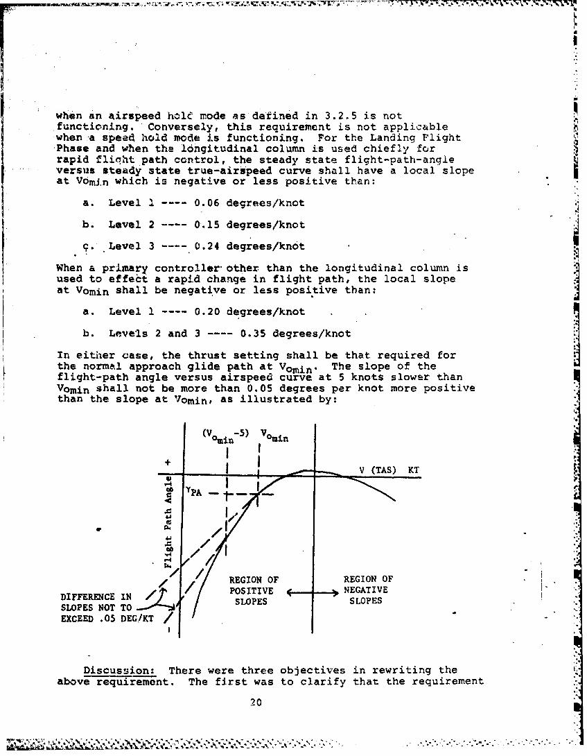
when an irspeed hole mode as defined in 3.2.5 is notfunctioning. Conversely, this requirement is not applicablewhen a speed hold mode is functioning. For the Landing FlightPhase and when the longitudinal column is used chiefly forrapid flicht path control, the steady state flight-path-angleversus steady state tru6-airspeed curve shall have a local slopeat Vomin which is negative or less positive than:
a. Level I 0.06 degrees/knot
b. Level 2 0.15 degrees/knot
9" Level 3 0.24 degrees/knot
When a primary controller other than the longitudinal column isused to effect a rapid change in flight path, the local slope
at Vomin shall be negative or less positive than:
a. Level 1 ---- 0.20 degrees/knot
b. Levels 2 and 3 0.35 degrees/knot
In either case, the thrust setting shall be that required forthe normal approach glide path at Vomin. The slope of theflight-path angle versus airspeed curve at 5 knots slower thanVomin shall not be more than 0.05 degrees per knot more positivethan the slope at Vomin, as illustrated by:
(V oin-5) Vom n
, ! . -. V (TAS) KT
4I4
AJ
0, REGION OF REGION OF
DIFFRENE ~POSITIVE NEGATIVESLPES NOT TO-SLOPES SLOPES
EXCEED .05 DEG/KT /
Discussion: There were three objectives in rewriting theabove requirement. The first was to clarify that the requirement
20
- - ..
did not apply when an airspeed hold mode was operating sincedy/dV would approach infinity. That is, the flight path anglecould be changed with little or no change in airspeed. Secondly,for conventional landings made using the column for flight pathcontrol, the dy/dV values of the general MIL-F-8785B (Reference 1)would apply. This requirement would apply to airplanes thatwere landed using the front-side control technique, regardlessof whether or not the airplane used that control technique duringSTOL landings. The third objective was to address an airplaneflown on the backside of the power required curve without anairspeed hold mode where the pilot must use thrust to controlflight path. The second set of dy/dV values in the above require-ment addresses that case. The Level 1 value was based on proto-type flight test results, and the Level 2 and 3 value was basedon SST simulation studies. NASA Ames studies have found thatdy/dV was not a good flying qualities parameter for STOL air-planes. This was concluded since as long as the pilot hadsufficient thrust and thrust response to control flight path,then the airplane could be operated at more positive values ofdy/dV than allowed by the second set above. The listed dy/dVvalues were provided, however, since sufficient thrust orthrust response may not be available. The above requirementwas a method of limiting the flight envelope to that whichwas felt to be reasonable.
2.20 3.2.1.3.1 Hands Off Flight-Path Stability. For Level 1,the airplane with cockpit controls free shall tend to return tothe trimmed y if it is perturbed from a trimmed flight conditionby any momentary input other than commanded steady state changesin speed or flight path (y).
Discussion: This requirement was taken from Reference 7,page 161, and the intent was to prevent the airplane fromdeviating from the trimmed flight path if left unattended bythe pilot. A phugoid about the trimmed y would be acceptable.
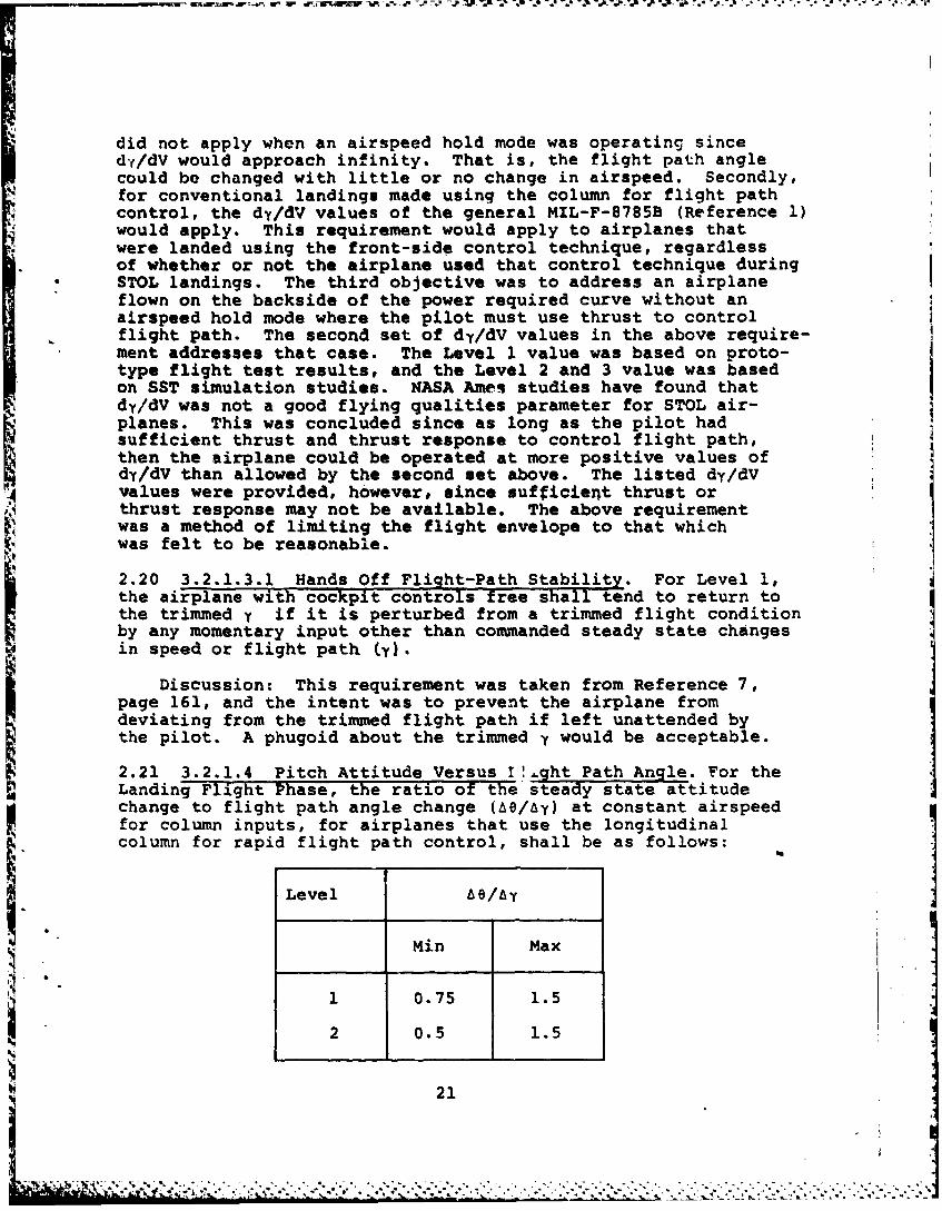
2.21 3.2.1.4 Pitch Attitude Versus 1!, ht Path Angle. For theLanding Flight Phase, the ratio of the steady state attitudechange to flight path angle change (Ae/ay) at constant airspeedfor column inputs, for airplanes that use the longitudinalcolumn for rapid flight path control, shall be as follows:
Level be/,&
Min Max
1 0.75 1.5
2 0.5 1.5
21
-P-7- 4? -. 19 .. . . . . . . . . .
Discussion: This requirement was based on References 7and 8. The Tntent was to ensure thac a STOL airplane thatuses the column to control flight path on the backside of thepower required curve would respond in a conventional manner.That is, for an airplane flying on the frontside of the powerrequired curve during a climb or descent at constant speed,the angle of attack is essentially constant. Hence, thefollowing derivation indicates why a AO/Ay of approximatelyone was required:
y + a
;b al-. and since ;a, is essentially zero for
conventional response: DO =l or AOY -Y A Y
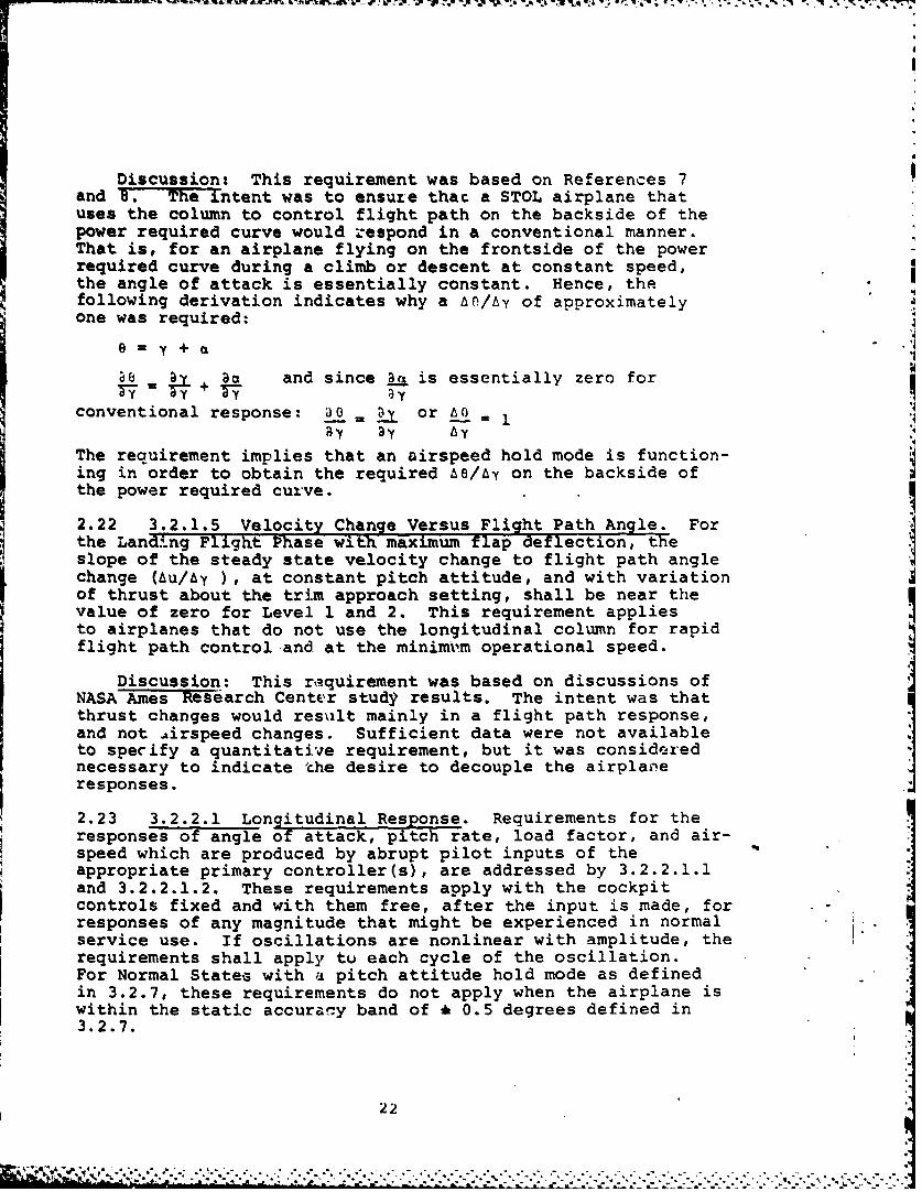
The requirement implies that an airspeed hold mode is function-ing in order to obtain the required e/A-y on the backside ofthe power required curve.
2.22 3.2.1.5 Velocity Change Versus Flight Path Angle. Forthe Landing Flight "Phase with maximum flap deflection, theslope of the steady state velocity change to flight path anglechange (Au/Ay ), at constant pitch attitude, and with variationof thrust about the trim approach setting, shall be near thevalue of zero for Level 1 and 2. This requirement appliesto airplanes that do not use the longitudinal column for rapidflight path control and at the minimfm operational speed.
Discussion: This raquirement was based on discussions ofNASA Ames Research Center study results. The intent was thatthrust changes would resilt mainly in a flight path response,and not irspeed changes. Sufficient data were not availableto specify a quantitative requirement, but it was considerednecessary to indicate the desire to decouple the airplaneresponses.
2.23 3.2.2.1 Longitudinal Response. Requirements for theresponses of angle of attack, pitch rate, load factor, and air-speed which are produced by abrupt pilot inputs of theappropriate primary controller(s), are addressed by 3.2.2.1.1and 3.2.2.1.2. These requirements apply with the cockpitcontrols fixed and with them free, after the input is made, forresponses of any magnitude that might be experienced in normalservice use. If oscillations are nonlinear with amplitude, therequirements shall apply tu each cycle of the oscillation.For Normal States with a pitch attitude hold mode as definedin 3.2.7, these requirements do not apply when the airplane iswithin the static accuracy band of • 0.5 degrees defined in3.2.7.
22
Discussion: Several items need to be clarified in thisintroductory paragraph to 3.2.2.1.1 and 3.2.2.1.2. The termshort period was not used since at the STOL flight conditionsthe roots of the characteristic equation may not be sufficientlyseparate to distinguish short period and phugoid motions.Damping and frequency requirements were specified not onlyfor angle of attack but also pitch rate and load factor sincewith a highly augmented airplane their characteristic equa-tions could be different. For an airplane that uses onlyelevator for pitch control, the characteristic equation forangle of attack, pitch rate and load factor should all be thesame. For a STOL airplane, elevator, thrust and direct liftcontrol (DLC) could result in different characteristicequations for each of the defined responses. The requirementswere intended to apply only with the pilot in the loop (i.e.,ou ide the static accuracy band of t 0.5 degrees of thepitch attitude hold mode).
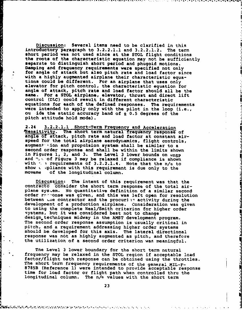
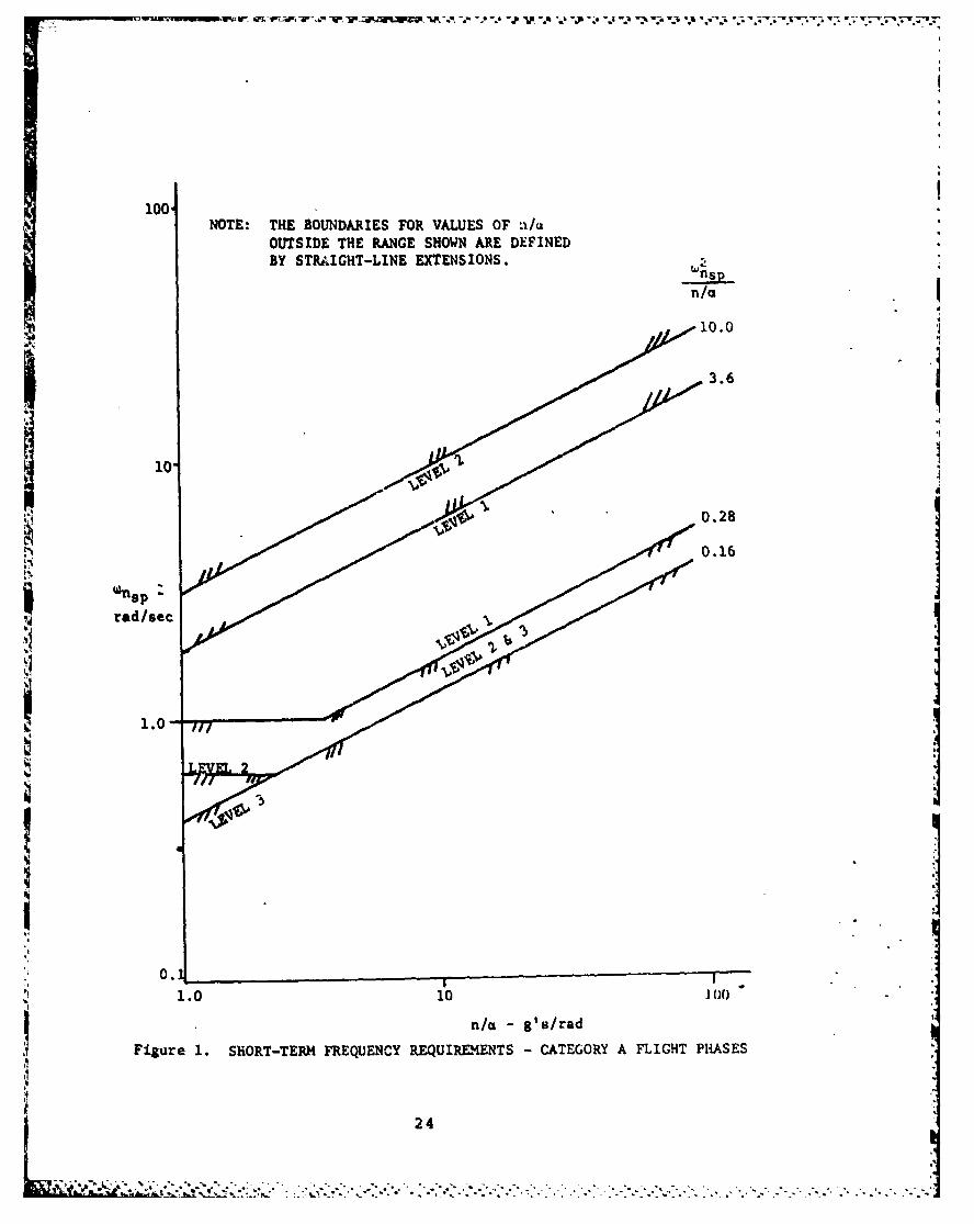
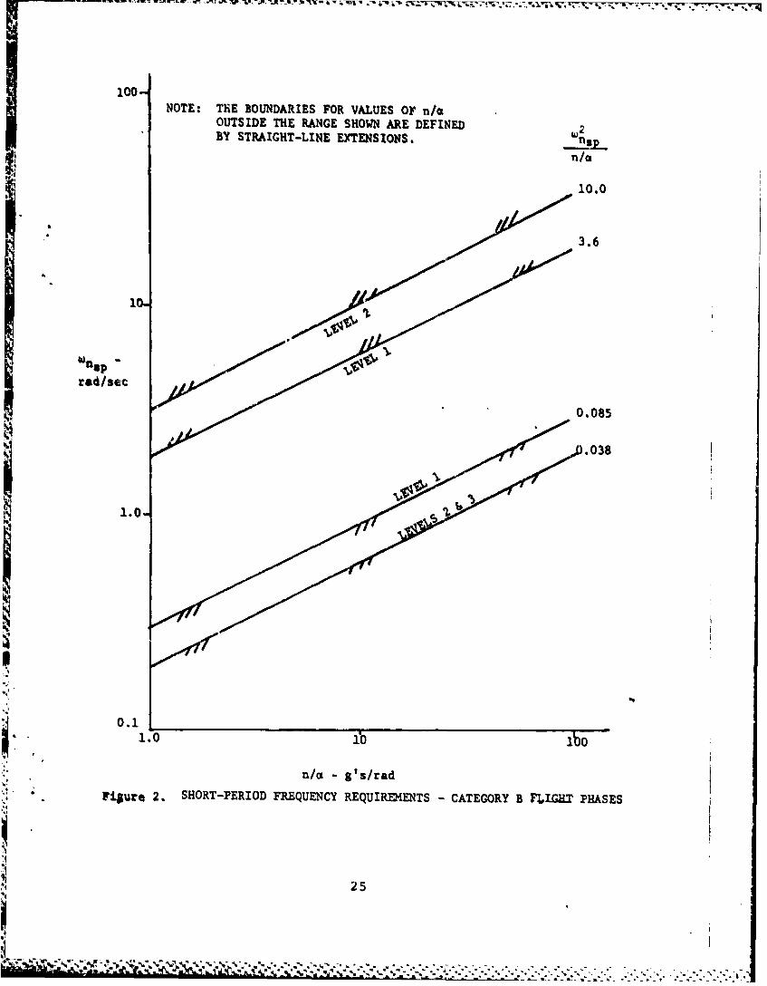
2.24 3.2.2.1.1 Short-Term Frequency and AccelerationOensitivit. The short term natural frequency response ofangle o attack, pitch rate and load factor at constant air-speed for the total airplane aerodyiiamics, flight controls,augment-'ion and propulsion system shall be similar to asecond order response and shall be within the limits shownin Figures 1, 2, and 3. The Level 3 lower bounds on wnspand n of Figure 3 may be relaxed if compliance is shownwith i requirements of 3.2.2.1.4. Note that the n/a toshow -,pliance with this requirement is due only to themoveme of the longitudinal column.
Discussion: The intent of this requirement was that thecontracto consider the short term response of the total air-plane system. No quantitative definition of a similar secondorder r -,onse was given, and this was left open for resolutionbetween %.ae contractor and the procuri i activity during thedevelopment of a production airplane. Consideration was givento using the complete Neal/Smith criterion for higher ordersystems, but it was considered best not to changedesignptechniques midway in the AMST development program.The second order response assumption is usually critical inpitch, and a requirement addressing higher order systemsshould be developed for this axis. The lateral directionalresponse was not as highly augmented as pitch, and thereforethe utilization of a second order criterion was, meaningful.
The Level 3 lower boundary for the short term naturalfrequency may be relaxed in the STOL region if acceptable loadfactor/flight Dath response can be obtained using the throttles.The short term frequency requirements of the general MIL-F-8785B (Reference 1) were intended to provide acceptable responsetime for load factor or flight path when controlled thru thelongitudinal column. The n/a values with the short term
23
100.NOTE: THE BOUNDARIES FOR VALUES OF n/x
OUTSIDE THE RANGE SHOWN ARE DEFINEDBY STRAIGHT-LINE EXTENSIONS.
n/a
S3.6
110.
I'I
red/sec
1.0
II
0.1
1.0 10 l.0
-/ g's/radI Figure 1. SHORT-TERM FREQUENCY REQUIREMENTS -CATEGORY A FLIGHT PHASES
Snp24
_ _ _ _ _ _ _ _ _ _ _ _ __1 _ _ 0
X'u-* X; w . v* . v W .' ~ '
10-NOTE: THE BOUNDARIES FOR VALUES OF n/a
OUTSIDE THE RANGE SHOWN ARE DEFINEDBY STRAIGHT-LINE EXTENSIONS. -n.p
n/
10.0
* 3.6
10
rad/sec
, 0.085
.038
0.1
1.0 Tbo
n/a g's/rad
Filure 2. SHORT-PERIOD FREQUENCY REQUIREMENTS - CATEGORY B FLIC. PHASES
25
100* ~
NOTE: THE 3OUNDARIES FOR VALUES OF n/a GREATERTHAN 100 ARE DEFINED BY STRAIGHT-LINE EXTENSIONS. n,THE LEVEL 3 'UNDARY FOR n/m LESS THAN 1.0 ISALSO DEFINED BY A STRAIGHT-LINE EXTENSION.
3.6
10.
0.16
0.09
Ii
1.0 10 100n/a - g's/rad
Figure 3. SHORT-PERIOD FREQUENCY REQUIREMENTS - CATEGORY C FLIGHT PHASES
26
S""_
2 .~ .
natural frequency requirement would include the effects ofdirect lift and thrust if these are commanded via the longitu-dinal column.
2.25 '.2.2.1.2 Total System Damping. All longitudinalcharacteristic rootb due to airplane aerodynamics, flight con-trols, augmentation, and propulsion system which affect angleof attack, pitch rate, load factor and airspeed responseshall have damping that complies with Figure 4 for allCategories. The maximum damping ratio for the short termresponse shall be 1.3 and 2 for Levels I and 2, respectively.The Levels 2 and 3 requirements may be relaxed, as shown bythe dashed lines on Figure 4, for cases where 3.2.1.1.1permits relaxation of the static stability requirement(3.2.1.1) and for the Landing and Go-Around Flight Phases.In no case, however, shall the flight conditions that resultin a characteristic root in this relaxed area be sustainedfor more than 5 minutes.
Discussion: The intent of Figure 4 was to address allcharacteristic equation roots regardless of the system order.The short term response roots must also meet the frequencyrequirements of 3.2.2.1.1. The Levels 1, 2, and 3 require-ments apply for all Categories, and the solid lines of Figure4 were based on the general MIL-F-8785B (Reference 1). Thedamped frequency of 0.3 rad/sec was selected basedon ARST root locations as a reasonable boundary betweenshort term and long term modes. The relaxed regions forLevels 2 and 3 were based on SST approach simulation studies(References 10 &11) that indicated safe flying qualitieswere possible with root locations more unstable than allowedby Figure 4. Roots may be in the relaxed areas for only shortperiods of time to prevent high pilot workload or fatigue.
2.26 3.2.2.1.3 Residual Oscillation-. Any sustainedresidual oscillations shall not interie-e with the pilot'sability to perform the tasks required in service use of theairplane. For Levels 1 and 2, oscillations in normal accele-ration at the pilot's station greater than ± 0.02 g's willbe considered excessive for any flight phase.
Discussion: The ± 0.02 g's was selected tobe consistentwith paragraph 3.1.3.8 of the Flight Control System Specifi-C" cation (Reference 2) and because experience on the B-1 pro-
gram indicated the t 0.05 g's of the general MIL-F-8785B(Reference 1) was not satisfactory. The t 3 mils pitchattitude oscillations requirement of the general MIL-F-8785Bwas deleted since there was little confidence in it and nojustificatinn for it could be found.
27
L N , " "6"N"7 - . - "" -"-" -"-" - . - . ..-,.,, ' -,.,.. . . ,,
0.5 0.25 0.915 0.8 DAIAYPR
0.7
0.6
LEVEL 3
(SEE PARA.0 3 3.2.2.1.2)
REL~AXED
LEVELLEVEL 2
2~~ 2 SEC 5SE
aREAL PART RAD/SEC
FIGURE 4. SYSTEM DAMPING
28
2.27 3.2.2.1.4 Flight Path Response. The time response ofthe flight path angle changes in the Landing Flight Phaserequired by 3.2.3.2.1 shall be smooth. Ninety percent (90%)of the required change in flight path angle at the minimumoperational speed shall be obtained in less than 5 seconds,and at the speeds above and below the minimum operationalspeed, ninety percent of the flight path angle change mustbe obtained in less than 3 seconds after the pilot command.Following these time periods, the flight path angle shallremain within 1 0.5 degrees about the steady state value.The Figure below illustrates this requirement. This require-ment defines Level 1.
TIME - SEC
iv1 7 -- "'Z
FLIGHT - y
PATH - (PARA.
F At(PARA.3,2.2.1.4)
Discussion: This requirement was added to ensurethat the fligt path response to comand was rapid and that theI flight path change could be maintained. The time of 5 secondswas based on comparison with the B-1 flight path response timeduring approach, and was also recommended in Reference 5.The time of 3 seconds was suggested in Reference 4. Thetolerance band of * 0.5 degrees about the steady state valuewas selected arbitrarily.
2.28 3.2.2.2 Control Feel and Stability in ManeuveringFliqht. In steady turning flight and in pull-ups at constantspeed, the elevator control force and elevator control deflec-tion required to maintain a change in normal accelerationshall be in the same sense as those required to initiate thej load factor change; that is, airplane-nose-up control inputsto maintain an increase in normal acceleration, airplane-nose-down control inputs to maintain a decrease in normal accele-ration. These requirements apply to local gradients inconstant-airspeed maneuvers throughout the range of service
load factors defined in 3.1.8.4. This requirement appliesfor Levels 1 and 2.
29
. . . . ...-..4' " ' " . . . ' . ." " . . . ." - -' - - ' " " < - -' "
Discussion: The major difference between this requirementand the general MIL-F-8785B was that the surface deflectionrequired to maintain commanded normal acceleration was notspecified. This was deleted in order to allow flight aft ofthe maneuver point (6e/g=0), which may occur az low speeds inthe Service Flight Envelope with the flaps down. Augmentationwould be required in this region to provide Level 1 flyingqualities.
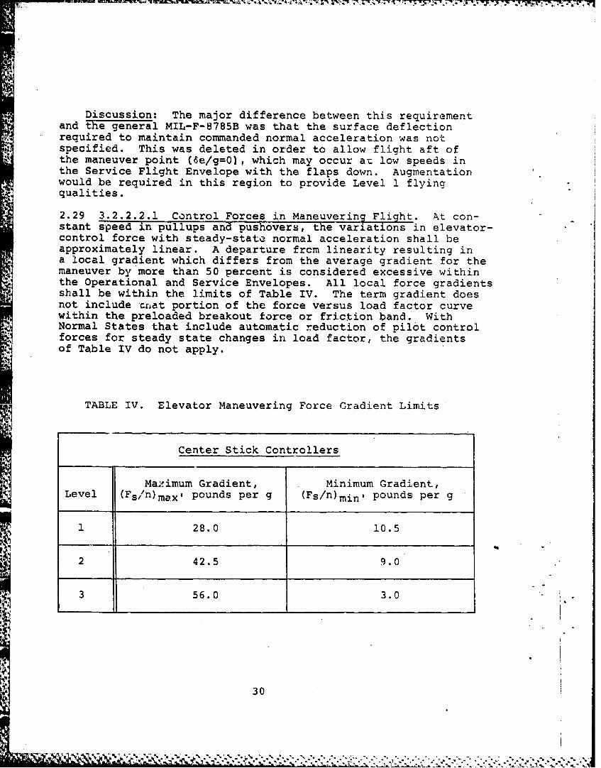
2.29 3.2.2.2.1 Control Forces in Maneuvering Flight. At con-stant speed in pullups and pushovers, the variations in elevator-control force with steady-state normal acceleration shall beapproximately linear. A departure frcm linearity resulting ina local gradient which differs from the average gradient for themaneuver by more than 50 percent is considered excessive withinthe Operational and Service Envelopes. All local force gradientsshall be within the limits of Table IV. The term gradient doesnot include crat portion of the force versus load factor curvewithin the preloaded breakout force or friction band. WithNormal States that include automatic reduction of pilot controlforces for steady state changes in load factor, the gradientsof Table IV do not apply.
-* TABLE IV. Elevator Maneuvering Force Gradient Limits
Center Stick Controllers
Mazimum Gradient, Minimum Gradient,Level (Fs/n)max , pounds per g (Fs/n)min , pounds per g
1 28.0 10.5
2 42.5 9.0
3 56.0 3.0 I.
30
I
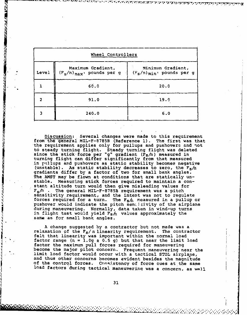
Wheel Controllers
Maximum Gradient, Minimum Gradient,Level (Fs/n)max , pounds per g (Fs/n)min, pounds per g
1 60.0 20.0
2 91.0 19.0
3 240.0 6.0
Discussion: Several changes were made to this requirementfrom the genera1 MIL-F-8785B (Reference 1). The first was that
the requirement applies only for pullups and pushovers and notto steady turning flight. Steady turning flight was deletedsince the stick for.e per "g" gradient (Fs/n) measured inturning flight can differ significantly from that measuredin pnllups and pushovers as static stability becomes negative(unstable). As static stability decreases to zero, the Fs/ngradients differ by a factor of two for small bank angles.stable. Measuring stick forces required to maintain a con-
stant altitude turn would then give misleading values forFs/n . The general MIL-F-8785B requirement was a pitchsensitivity requirement, and the intent was not to regulateforces required for a turn. The FsA measured in a pullup orpushover would indicate the pitch sen. 6itvity of the airplaneduring maneuvering. Normally, data taken in wind-up turnsin flight test would yield FsA values approximately the~same as for small bank angles.
A change suggested by a contractor but not made was arelaxation of the Fs/n linearity requirement. The contractorfelt that linearity was important within the normal loadfactor range (n = 1.0g 1 0.5 g) but that near the limit loadfactor the maximum pull forces required for maneuveringbecome the major pilot concern. Frequent maneuvering near thelimit load factor would occur with a tactical STOL airplane,and thus other concerns becomes evident besides the magnitudeof the control forces. Conistency of force cues at the sameload factors during tactical maneuverinq was a concern, as wi3ll
31
A*"P
as linearity and providing the pilot with sufficient forcecues to avoid overstressing the airplane. The entire subjectof maneuvering stick forces was very complex and one thatwould have to be solved by piloted simulation verified byflight test. Until that time when more information would beavailable, it was decided not to change the present MIL-F-8785Blinearity requirement.
Another change was that the requirement did not apply whenan automatic system reduced pilot stick forces during maneuverz.With such a system, there would be no steady state Fs/3.Pilots during the AMST flight testing found this type of systemto be acceptable, with the possible exceptions of power approachand aerial refueling. The Fs/n requirements should have appliedduring the transient portion of the maneuver before the auto-matic system reduced the forces to zero. This would haveassured the proper sensitivity for the load factor resultingfrom force application. This was not done since this AFFTCcomment was not available before the AMST Vroposal InstructionPackage was released. This transient requirement should beincorporated into future revision of the STOL flying qualitiesrequirements.
The actual stick forces in Table IV were based on a limitload factor of 3 except for the wheel, Level 1, minimum gradientwhich was found to be acceptable from flight test. The AMSThas a limit load factor of 3 with the flaps up, and 2 with theflaps down. Based on B-1 and AMST flight testing, the lowergradients were desired by the pilots and were considered accept-able. Flying the AMST aircraft with one hand was stated as arequirement by the Military Airlift Command which the forcelevels of Table IV made possible. The lower gradients have notresulted in overstressing the aircraft to date. Some pilotswere concerned about the ease with which the aircraft could beoverstressed and a "g" limit warning system was suggested.
2.30 3.2.3.2 Longitudinal Control in Maneuvering Flight. Withinthe Operational Flight Envelope speed range, it shall be possible,except-where limited by stall or structural limits, to developthe following range of load factors by use of the primarylongitudinal control surface alone:
LEVEL ncmax ncmin
1 3.0 0.02 2.0 0.253 1.25 0.75
This maneuvering capability is requirdc] at the 1.q I-rim spn"vwand over a range about tho trim spend the 1us.c-r (f +15 1,,.r-cent or +50 knots equivalent airspeed at constant alLitud(except where limited by the boundaries of the OperationalFlight Envelope). Trim and throttle settings shall not bechanged by the crew. Within the Service and Permissible
Flight Envelopes, the dive-recovery requirements of 3.2.3.5and 3.2.3.6, respectively, shall be met.
Discussion: The Level 1 load factor capabilities statedabove were based on the posi':ive structural limit load factor,and the minimum load factor anticipated to be required toperform the defined missions. The Levels 2 and 3 requirementswere based on judgement, although one contractor had performedstudies with the SST that indicated the Level 3 values weresufficient for emergency conditions. The speed range over whichthe maneuver capability shalIL be demonstrated was defined atconstant altitude so that Mach effects were included.
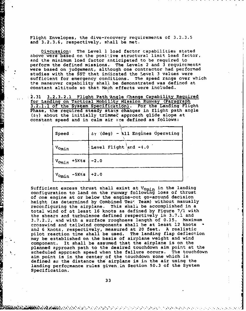
2.31 3.2.3.2.1 Flight Path'Angle Change Capability Requiredfor Landing on Tactical Mobillty Mission Runway (Paragraph3.2.1.1 of the System Specificitionl. For the Landing FlightPhase, the required steady stats changes in flight path angle(by) about the initially trimmeC approach glide slope atconstant speed and in calm air tLre defined as follows:
Speed by (deg) - All Engines Operating
Vomin Level Flight'and -4.0
Vomin +5Kts -2.0
Vomin -5Kts +2.0
Sufficient excess thrust shall exist at Vomin in the landingconfiguration to land on the runway following loss of thrustof one engine at or below the engine-out go-around decisionheight (as determined by Combined Te'. Team) without manuallyreconfiguring the airplane. This shall be accomplished in atotal wind of at least 16 knots as defined by Figure 7/1 withthe shears and turbulence defined respectively in 3.7.1 and3.7.2.2, and with a surface roughness length of 0.15. Maximumcrosswind and tailwind components shall be at least 12 knotsand 6 knots, respectively, measured at 20 feet. A realisticpilot reaction time shall be used. The landing flap deflectionmay be established on the basis of airplane weight and windcomponent. It shall be assumed that the airplane is on theplanned approach path to the desired touchdown aim point at thescheduled apprcach speed when the failure occurs. The touchdownaim point is in the center of the touchdown zone which isdefined as the distance the airplane is in the air using thelanding performance rules given in Section 50.3 of the SystemSpecification.
33
For landings made at the field with an engine failed, wherethe engine failure has occurred above the engine-out go-arounddecision height, sufficient excess thrust shall exist at Vom nthat the normal approach flight path angles can be maintaineA.This shall be accomplished in a total wind of at least 23 knotsas defined by Figure 7/1 with the shear and turbulence definedrespectively in 3.7.1 and 3.7.2.2, and with a surface roughnesslength of 0.15. Maximum crosswind and tailwind components shallbe at least 19 knots and 10 knots, respectively, measured at 20feet. The landing flap deflection selected for engine-outlanding approaches may be established as a function of weight
and wind component. To satisfy this requirement, a flight pathangle change capability of +2 degrees in calm air is requiredin addition to that requirea to maintain normal approach flightpath angles in the above stated winds, shears and turbulence.No manually commanded configuration changes are permitted.
The above capabilities must be demonstrated for the weightat the midpoint of the Tactical Mobility Mission defined in theSystem Specification, 1030F hot day air temperature, and atsea level.
Thrust reductions to stall warning are permitted to demon-strate the required negative changes in flight path angle.For this requirement, all aircraft systems shall be functioningnormally, except for the failed engine.
Discussion: This requirement had no counterpart in thegeneral MIL-F-6785B (Reference 1). The requirement was addedto specify the minimum flight path control required for STOLoperation. The requirement could have a direct impact onsizing the engines since thrust would be the primary means ofcontrolling the flight path on the backside of the powerrequired curve. For this reason, the requirement- was discussedmore than all the other changes made to the general MIL-F-8785Band was the most controversial. The basis for the requirementwas work done by the NASA Ames Research Center and reportedin References 4 and 5. Capability to change the flight pathwas necessary to track to a desired aim point and to correct
flight path errors due to the pilot, turbulence or wind shears.Three different cases were addressed in the requirement: AllEngines Operating (AEO) and Critical Engine Inoperative (CEI)below and above the engine-out go-around height. The criticalcase would be the CEI landing where the engine failure occurredabove the go-around decision height. Maximum available thrustwould be reduced due to the engine failure, and since theprobability of this case occurring would be greater than theone where an engine failure occurred below the go-arounddecision height, higher wind and shear magnitudes must beaccounted for in the design. The winds and surface roughnesslength defined in the requirement were based on ENFTC judgement.No manually commanded configuration changes were allowed once
34
- ; € ~............ . .......... ...................... ...... ...
the landing approach was begun in order to minimize pilotworkload. What the configuration change should be would alsobe difficult to determine since it would be a function of thewinds or shears encountered. The configuration change wouldalso take time which may not be available when close to theground. Manual configuration changes would take longer thanautomatic since the command must be stated verbally to thecopilot who must then respond.
The flight path change of -4 degrees with AEO would resultin a total flight path angle of -10 degrees for a -6 degreesSTOL approach angle. A capability near this magnitude wasrequired for capturing the STOL glide slope from level flight.Negative corrections to the flight path are not as criticalas positive corrections since if the pilot cannot correctdownward, a go-around could be commanded and safety notcompromised. The pilot must make upward corrections or riskshort or high sink rate landings.
For clarification, the touchdown aim point was the centerof the touchdown zone which was defined as the distance theairplane was in the air from a 50-foot altitude at the runwaythreshold to main gear touchdown. This definition for thetouchdown zone was used to be consistent with the performancecalculation ground rules and since no firm touchdown zonedistance was otherwise defined by the procuring activity orMAC. Further, for the CEI landings with the engine failedabove the go-around decision height, the requirement was tochange the flight path angle +2 degrees about the flight pathangle required to land in a 23 knot shearing headwind. Aheadwind is mentioned here since paragraph 3.7.1 states thatthe total wind can be from any direction, and a headwind wouldbe the worse case. This 23 knot shearing headwind would havea value of 41 knots at 1,000 feet altitude, which was assumedto be the altitude for the start of final approach. Shearingeffects at 1,000 feet would be minimal, but as the altitudedecreases, the flight path change capazbi.lity (Ay) required tocompensate for shearing would increase, while the Ay requiredto compensate for the decreasing headwind would decrease. Theay required for shearing would dominate, and therefore thecritlical case would be near the ground in a shearing headwind.
2.32 3.2.3.2.1.a Landing in Turbulence. Level 1 flyingqualities are required for a landing on the short field defined
* in paragraph 3.2.1.1 of the System Specification in a total windof at least 25 knots as defined in 3.7.1, Figure 7/1. The shearsand turbulence corresponding to this total wind shall also beconsidered and are defined in 3.7.1 and 3.7.2.2, respectivgly,using a surface roughness length of 0.15. For this requirement,maximum crosswind and tailwind components shall be at least 25knots and 10 knots, respectively, measured at 20 feet.
JAll airplane systems are assumed to be operating normally.
35
I 2V
The weight at the midpoint of the Tactical Mobility Missiondefined in the System Specification, 1030F hot day airtemperature, and at sea level shall be used for the analysis.
Discussion: Paragraph 3.2.3.2.1.a stated that Level 1flying qualities were necessary for STOL landings in winds up tothose stated, while paragraph 3.2.3.2.1 defined the overallairplane performance required for STOL flight path tracking.Note that a 25 knot crosswind at 20 feet corresponds to a 30knot crosswind at 5.0 feet using the turbulence model ofSection 3.7. A 30 knot crosswind capability was desired by MAC.The 10 knot tailwind for STOL landing was mentioned by pilotsas being the maximum feasible. Tailwind capability was requiredsince in a wartime environment landings may be required in onlyone direction, or time may not be available to go-around andland from the other direction if winds suddenly change.
2.33 3.2.3.2.2 Turn Rate. During the Landing Flight Phase,at the maximum possible pilot selected flap deflection (con-tractor may specify specific number), a constant turn rate of7.5 degrees per second is required for Level 1 at the minimumoperational speed and on the trimmed approach glide slope. Thiscondition shall be demonstrated for the weight at the midpointof the Tactical Mobility Mission defined in the System Speci-fication, 103 0F hot day air temperature, all engines operatingand at sea level.
Discussion: The intent of this requirement was to providea sustained turn rate capability for correcting offsets fromthe runway, avoiding ground fire and other maneuvering tasks.-The 7.5 degree/second turn rate was based on-the sustainedload factor avairable (i.e., thrust used to maintain loadfactor) for one of the AMST prototypes at the STOL approachspeed. This should provide an acceptable turn rate capabilityon final based on pilot comments. An 1100 foot turn radiusresulted from the 7.5 degree/second turn rate at the STOLapproach speeds.
2.34 r3.2.3.3 Longitudinal Control in Takeoff. The effective-ness of the el-e.ator control shall not restrict the takeoffperformance required of the airplane and defined in the SystemSpecification,. and shall be sufficient to prevent over-rotationto undesirable attitudes during takeoffs. Satisfactory take-offs shall not be dependent upon use of the trimmer controlduring takeoff or on complicated control manipulation by thepilot. These requirements shall be met on hard-surfaced run-ways and unprepared fields that are specified in the System-Specification. This requirement defines Levels 1, 2, and 3.
Discussion: The requirement in the general MIL-F-8785B(Reference .1) was that the effectiveness of the elevator controlcould not restrict the takeoff performance, and to obtain nose
36
wheel liftoff at 0.9 Vmin or less. The 0.9 Vmin requirementwas deleted in the AMST wording since meeting that requirementwould not assure that the takeoff distance would be achieved.Not restricting takeoff distance was the major intent of thegeneral MIL-F-8785B requirements.
2.35 3.2.3.4 Longitudinal Control in Landing. The elevatorcontrol shall be sufficiently effective in the Landing FlightPhase in ground effect that the geometry limited touchdownattitude or the stall angle of attack can be maintained withany thrust setting. This requirement shall be met with the
-* airplane trimmed for the minimum operational speed in free air.The requirements above define Levels 1 and 2. For Level 3, itshall be possible to execute safe approaches and landings inthe presence of a 15 kt total mean wind, roughness length of0.15 and associated turbulence levels as defined in paragraph3.7.2.2.
Discussion: This requirement was altered to account forthe fact that a STOL airplane may not be able to maintain levelflight at the geometry limited touchdown attitude. Recognitionthat the stall angle of attack (or stall speed) was a functionof thrust for a STOL airplane was also added. The general MIL-F-8785B (Reference 1) required safe approaches and landingsin atmospheric disturbances and the AMST specification quanti-fied these disturbances using engineering judgement. The 15knot wind of the requirement was intended only as a direct head-wind.
2.36 3.2.3.4. Landing Control Power. A load factor (n) of.2g's shall oz bavaiable for flare at the minimum operational
speed before the stall warning is encountered. The require-ment applies for the Landing Flight Phase, with trim set forapproach, without ground effects, and with an initial thrustsetting required for the approach configuration and airspeed.This requirement applies for Levels 1, 2, and 3.
Discussion: This requirement was added in the AMST specifi-cation to insure that load factor capability was available toflare the airplane f- , high rates of sink (16 fps) or to makelast-second z' ~ct. to avoid landing short. This require-ment evolved irom the criteria presented in Section 5.4.2.1 3fReference 7. The initial concern to provide flare capabilitywas not warranted based on flight test experience for normaloperation. Pilots did not intentionally flare the airplane forSTOL landing, but trie o hold pitch attitude constant andrely on ground effect j reduce the sink rate. However, someflare capability must oe available to arrest higher than normalsink rates due to winds or pilot errors when near the ground.
2.37 3.2.3.4.3 Pitch Acceleration. With the aircraft initiallytrimmed at the minimum operational speed for the Landing FlightPhase, it shall be possible to achieve a 3-degree attitude
37

change within one second due to longitudinal column stepinput only. This requirement defines the minimum Level 1capability and shall be demonstrated in the most critical steadysideslip required for enrine-out or crosswind (3.3.7) and out ofground effects.
Discussion: This requirement was added to the AMST speci-fication based on References 3 and 7. The intent of therequirement was that last-second capability exist to preventstriking the nose gear first on STOL landings. STOL airplaneswill generally land at a lower pit h attitude than conventionalairplanes. The reason for this is that the angle of attack forSTOL and CTOL will be in the region of 7-8 degrees, but theflight path angle for STOL will be near -6 degrees while forCTOL it is near -3 degrees. Thus, STOL pitch attitudes will beapproximately 1 to 2 degrees while for CTOL, pitch attitudesare 4 to 5 degrees. Operation in tailwinds could further reducethe STOL pitch attitude to -l to 0 degrees due to the higherflight path angles required to track to a desired touchdownpoint. STOL pitch attitude must also be kept low for goodpilot visibility on the steep STOL flight path.
2.38 3.2.3.5 Longitudinal Cwntrol Forces in Dives - ServiceFlight Envelope. With the airplane trimmed for level flightat speeds throughout the Service Flight Envelope, the elevatorcontrol forces in 7.5 degree dives held for at least 20 secondsduration within the Service Flight Envelope shall not exceed 30
pounds push or 15 pounds pull. In similar dives, but with trimoptional following the dive entry, it shall be possible withnormal piloting techniques to maintain the forces within thelimits of 10 pounds push or pull. The forces required forrecovery from these dives shall be in accordance with thegradients specified in 3.2.2.2.1 although speed may vary duringthe pullout. In no case shall the forces be greater than 100pounds during the pullout.
Discussion: The major change from the general MIL-F-8785B(Reference 1) was that the dive maneuver was defined basedon FAR Part 25, as discussed in 2.7 above. The 100 poundsallowed as the maximum for dive recovery were based onengineering judgement.
2.39 3.2.4 Pitch Attitude Command. For a pitch attitudecommand mode, the pitch attitude of the aircraft shall be pro-portional to a longitudinal column displacement from the pitchcontrol trim position. A push force and forward cockpit con-trol displacement shall be required to decrease pitch attitude,and a pull force and aft cockpit control displacement shall berequired to increase the pitch attitude. When the column isdisplaced in either direction and then released, the aircraftshall return to the initially referenced attitude unless thereferenced attitude has been changed by a pilot or automaticcommand. The commanded pitch attitude change versus time shallbe smooth, and the required performance define] (i.e., ovprshoot,
time history eavelopes, etc.) by the contractor. The limitson the change in pitch attitude to the pilot stick force shallbe defined by the contractor based on prototype flight testresults.
Discussion: The intent of this added requirement was todescribe in general what an attitude command mode must do,and then let the contractor define the performance character-istics of the mode based on acceptable prototype flight testresults. Simulation and analysis could be used to define thscharacteristics of the mode as long as a comparison with flighttest data could be made.
2.40 3.2.5 Airspeed Command and Hold Modes. The command air-speed change versus time shall be smooth and the desired per-formance defined (i.e., overshoots, time history envelopes,etc.) by the contractor. For an airspeed hold mode, the air-speed selected by the pilot shall be the reference. Indicatedairspeed shall be maintained within +5 knots or +2 percent ofthe referenced airspeed, whichever is greater, excepting gustspikes with a duration less than 2 seconds., in the followingatmospheric environment:
Low Altitude - 25 kt total wind using 3.7.1 with a rough-ness' length of 0.15 and a correspondingturbulence as defined in 3.7.2.2.
High Altitude - Use turbulence levels associated with theprobability of exceedence of 10-2 as
% 4defined in Figure 7/6.
Any periodic oscillation within this limit shall have aperiod of at least 20 seconds.
Discussion: The performance characteristics of a commandairspeed mode shall be defined by the contractor, and shall bebased on acceptable prototype flight tat results. The air-speed hold mode requirements were based on paragraph 3.1.2.7of Reference 2. Reference 2 requirements were included in theflying qualities specification since at the initiation of thedevelopment of these requirements, it was not clear whether theprocuring activity was going to specify flight control system(FCS) requirements or not. FCS requirements were eventuallywritten by the-procuring activity, but for convenience, thespeed hold requirements were left in the flying qualities speci-I. " fication. The atmospheric environments were based on paragraphs3.1.2.9 and 3.1.3.7.1 of Reference 2, respectively, for the lowand high attitudes. Momentary large airspeed excursions dueto gust spikes were allowed since no long term degradation ihairspeed hold capabilities resulted.
2.41 3.2.6 Pitch Rate Command Mode. For a pitch rate commandmode, the pitch rate of the aircraft shall be proportional to
39
albngitudinal column displacement from the pitch control trimposition. A push force and forward cockpit control displacementshall be required for an airplane nose-down pitch rate, and apull force and aft cockpit control displacement shall berequired for an airplane nose-up pitcn rate. The commandedpitch rate time history shall be smooch and the required perform-ance defined (i.e., overshoot, time history envelopes, etc.) bythe contractor. The limits on the change in pitch rate to thepilot stick force shall be defined by the contractor based onprototype flight test results.
Discussion: Same comments as made under 2.39.2.42 3.2.7 Pitch Hold Mode. In those airplane states that
include attitude bold modes, the airplane shall maintainreferenced pitch attitudes throughout the Operational FlightEnvelope in the presence of longitudinal trim changes associatedwith thrust changes, secondary control system operation, normalconfiguration changes, during lateral-directional maneuversnormally required for mission accomplishment, and in the followingatmospheric environment:
Low Altitude - 25 kt total wind using 3.7.1 with a roughnesslength of 0.15 and a corresponding turbulenceas defined in paragraph 3.7.2.2.
High Altitude - Use turbulence levels associated with aprobability of exceedence of 10-2 asdefined in Figure 7/6.
Specifically, attitudes shall be maintained in smooth air withstatic accuracy of +0.5 degree pitch attitude (with wings level)with respect to the-reference. RMS attitude deviations shallnot exceed 2 degrees in pitch turbulence at the intensities Ispecified'. Accuracy requirements shall be achieved and main-tained within 3 seconds for either a 5 degree attitude ora0.5 "g" load factor disturbance, whichever is less, caused bya gust input.
Discussion: This requirement was based initially on para-grap 3.1.2. of Reference 2, but evolved further throughdiscussions with the contractors and the Air Force Flight TestCenter. Pitch hold mode requirements were included in theflying quality requirements because pitch attitude hold hadbecome an integral part of flying the airplane during STOLlandings. The pitch hold mode provides a pseudo speed holdmode since it holds a referenced pitch attitude and the pilot.controls the flight path, and hence, angle of attack and air-speed tend to hold a desired value. The atmospheric environ-ment was based on Reference 2 as discussed in 2.40. The 2 |degrees RMS attitude deviation (versus the 5 degrees ofReference 2) was suggested by one of the contractors and was
40
" ."l '. -4 *.l- .-< . . . *, " . - 4 * . . , 4 -' . ." ' - ", ". ." .." . . , ""''\......-' ' '.... .-.. '-:/.. "..'."- " " , * -*..''
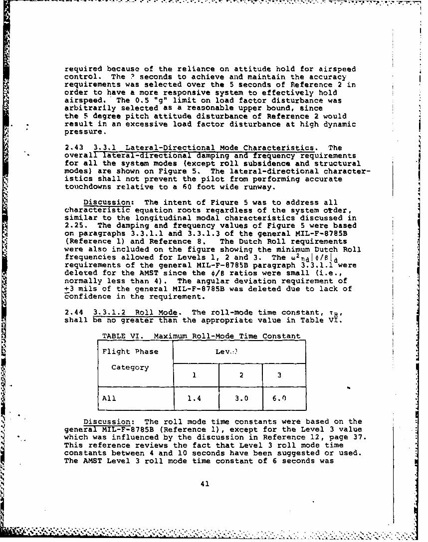
'I'
required because of the reliance on attitude hold for airspeedcontrol. The ? seconds to achieve and maintain the accuracyrequirements was selected over the 5 seconds of Reference 2 inorder to have a more responsive system to effectively holdairspeed. The 0.5 "g" limit on load factor disturbance wasarbitrarily selected as a reasonable upper bound, sincethe 5 degree pitch attitude disturbance of Reference 2 wouldresult in an excessive load factor disturbance at high dynamicpressure.
2.43 3.3.1 Lateral-Directional Mode Characteristics. Theoverall lateral-directional damping and frequency requirementsfor all the system modes (except roll subsidence and structuralmodes) are shown on Figure 5. The lateral-directional character-istics shall not prevent the pilot from performing accuratetouchdowns relative to a 60 foot wide runway.
Discussion: The intent of Fiqure 5 was to address allcharacteristic equation roots regardless of the system otder,similar to the longitudinal modal characteristics discussed in2.25. The damping and frequency values of Figure 5 were basedon paragraphs 3.3.1.1 and 3.3.1.3 of the general MIL-F-8785B(Reference 1) and Reference 8. The Dutch Roll requirementswere also included on the figure showing the minimum Dutch Rollfrequencies allowed for Levels 1, 2 and 3. The w2ldIi/8Idrequirements of the general MIL-F-8785B paragraph 3.3.1.1 weredeleted for the AMST since the 0/8 ratios were small (i.e.,normally less than 4). The angular deviation requirement of+3 mils of the general MIL-F-8785B was deleted due to lack ofFonfidence in the requirement.
2.44 3.3.1.2 Roll Mode. The roll-mode time constant, TR ,
shall be no greater than the appropriate value in Table VI.
TABLE VI. Maximum Roll-Mode Time Constant
Flight Phase Lev,!)
Category1 2 3
All 1.4 3.0 6.0
Discussion: The roll mode time constants were based on thegeneral MIL-F-8785B (Reference 1), except for the Level 3 value
• which was influenced by the discussion in Reference 12, page 37.This reference reviews the fact that Level 3 roll mode timeconstants between 4 and 10 seconds have been suggested or used.The AMST Level 3 roll mode time constant of 6 seconds was
41
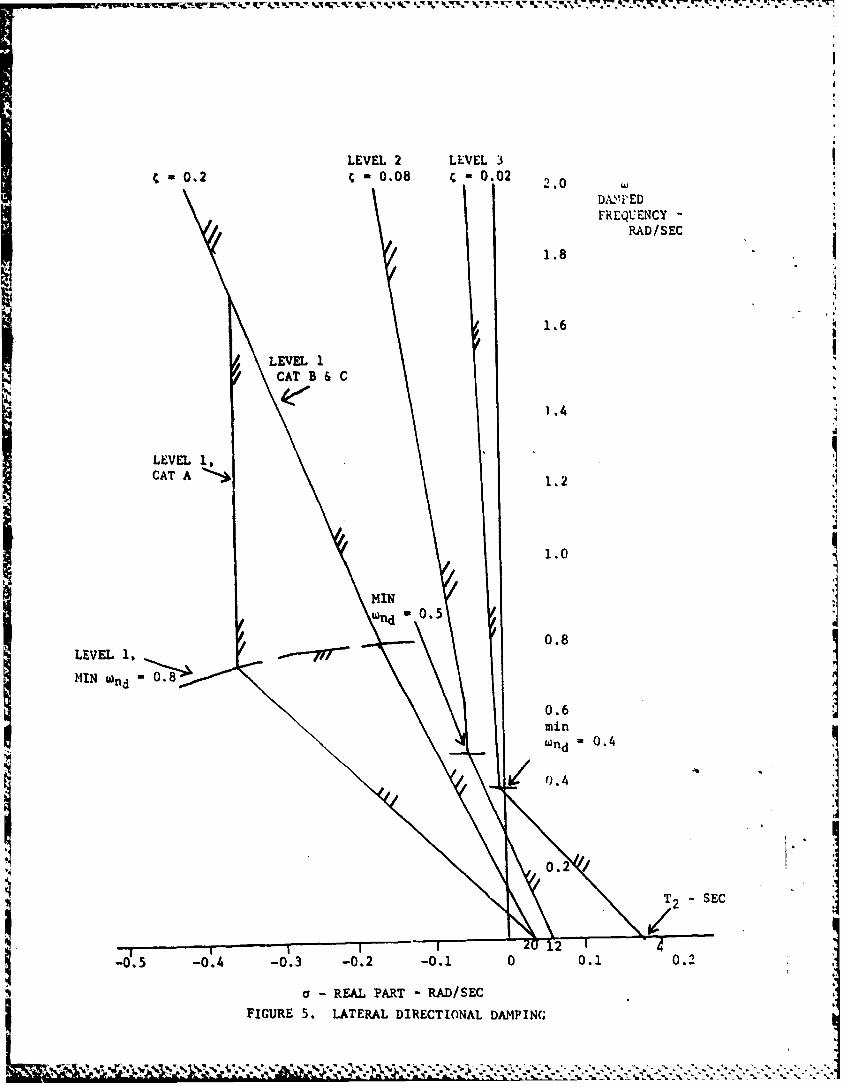
J.F
LEVEL 2 LEVEL 3c 0.2 0.08 C 0,02 2.0
\ ! DA,1,ED
FREQUENCY -
RAD/SEC
1.8
1.6
LEVEL ICAT B &C
1.4
LEVEL 1,CAT A 121.2
1.0
MIN
Wfld -0.5
0.8LEVEL 1
MINK WdO0. 8 ]0.6minwnd = 0.4 I
0.2/
T2 SECJ
,0I -t 2012-0.5 -. 4 -0.3 -0.2 -0.1 0 0.1 0.2
. - REAL PART - RAD/SEC
FIGURE 5. LATERAL DIRECTIONAL DAMPINCG
... .... ~' % % h$ ~ ~ % . _ ;p . I
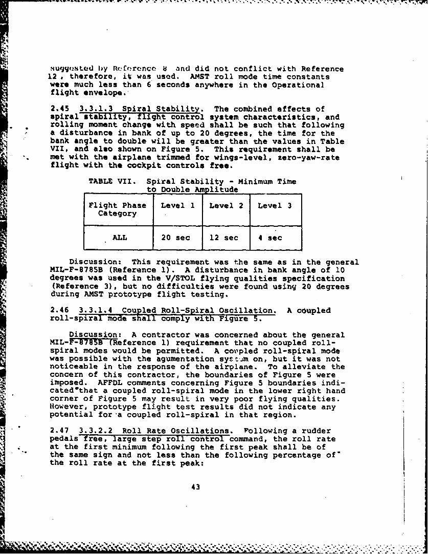
suqgt.stLd by Rcfrnrnce 8 and did not conflict with Reference12 , therefore, it was used. AMST roll mode time constantswere much less than 6 seconds anywhere in the Operationalflight envelope.
2.45 3.3.1.3 Spiral Stability. The combined effects ofspiral stability, flight control system characteristics, androlling moment change with speed shall be such that followinga disturbance in bank of up to 20 degrees, the time for thebank angle to double will be greater than the values in TableVII, and also shown on Figure 5. This requirement shall be
-. met with the airplane trimmed for wings-level, zero-yaw-rateflight with the cockpit controls free.
TABLE VII. Spiral Stability - Minimum Timeto Double Amplitude
Flight Phase Level 1 Level 2 Level 3Category
ALL 20 sec 12 sec 4 sec
Discussion: This requirement was the same as in the generalMIL-F-8785B (Reference 1). A disturbance in bank angle of 10degrees was used in the V/STOL flying qualities specification(Reference 3), but no difficulties were found using 20 degreesduring AMST prototype flight testing.
2.46 3.3.1.4 Coupled Roll-Spiral Oscillation. A c6upledroll-spiral mode shall comply with Figure 5.
Discussion: A contractor was concerned about the generalMIL-FI15Teference 1) requirement that no coupled roll-spiral modes would be permitted. A coupled roll-spiral modewas possible with the agumentation sysi=m on, but it was notnoticeable in the response of the airplane. To alleviate theconcern of this contractor, the boundaries of Figure 5 wereimposed. AFFDL comments concerning Figure 5 boundaries indi-cated'that a coupled roll-spiral mode in the lower right handcorner of Figure 5 may result in very poor flying qualities.However, prototype flight test results did not indicate anypotential for a coupled roll-spiral in that region.2.47 3.3.2.2 Roll Rate Oscillations. rollowing a rudder
pedals free,-large step roll control command, the roll rate
the same sign and not less than the following percentage of'
the roll rate at the first peak:
43
I-.-A
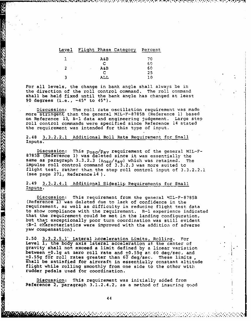
Level Flight Phase Category Percent
1 A&B 70C 60
2 A&B 60C 25
3 ALL 10
For all levels, the change in bank angle shall always be inthe direction of the roll control command. The roll commandshall be held fixed until the bank angle has changed at least90 degrees (i.e., -450 to 450).
Discussion: The roll rate oscillation requirement was mademore stringent than the general MIL-F-8785B (Reference 1) basedon Reference 13, B-1 data and engineering judgement. Large steproll control commands were specified since Reference 14 statedthe requirement was intended for this type of input.
2.48 3.3.2.2.1 Additional Roll Rate Requirement for SmallInputs.
Discussion: This Posc/Pav requirement of the general MIL-F-8785B (Reference 1) was deleted since it was essentially thesame as paragraph 3.3.2.3 (osc/Oav) which was retained. Theimpulse roll control command of 3.3.2.3 was more suited toflight test, rather thun the step roll control input of 3.3.2.2.1(see page 271, Reference 14 ).
2.49 3.3.2.4.1 Additional Sideslip Requirements for SmallInputs.
Discussion: This requirement from the general MIL-F-8785B(Referenc&e iTwas deleted due to lack of confidence in therequirement, as well as difficulty in reducing flight test datato show compliance with the requirement. B-1 experience indicatedthat the requirement could be met in the landing configuration,but that exceptionally poor turn coordination was still evident,B-1 c1aracteristics were improved with the addition of adverseyaw compensation).
2.50 3.3.2.5.1' Lateral Acceleration Limits, Rolling. ForLevel 1, the body axis lateral acceleration at the center ofgravity shall not exceed a limit defined by a linear variationbetween +0.lg at zero roll rate and +0.55g at 60 deg/sec, and+0,55g fEr roll rates greater than 60 deg/sec. These limits .ghall be satisfied for aircraft in essentially constant altitudeflight while rolling smoothly from one side to the other withrudder pedals used for coordination.
Discussion: This requirement was initially a6ded fromPeference 2, paragraph 3.1.2.4.2, as a method of insuring good
44
turn coordination. It was added since it was questionableif there was going to be a procuring activity Flight ControlSystem specification as mentioned in 2.40. The actual accel-erations allowed at the center of gravity were based on AMSTprototype flight test, and were found to be acceptable. Thevalidity of this requirement is questionable since for a pilotcoordinated turn, the accelerations should be related to thepilot station and not the center of gravity.
2.51 3.3.2.6 Turn Coordination. For Level 1, the sideslipangle shall not be greater than two degrees and lateral accel-er tion shall not exceed 0.03g durin steady coordinated -fsin either direction using 45 degrees of bank. Rudder pedalforce shall not exceed 40 pounds. It shall be possible to ..perform steady turns at the same bank angles with rudder pedals.free, with a roll stick force not exceeding five pounds or aroll wheel force not exceeding 10 pounds. The force require-ments constitute Levels 1 and 2 with the airplane trimmed forwings-level constant flight path and heading angle flight.
Discussion: The general MIL-F-8785B -(Reference 1) require-ment was modified with the intention of making it more specificusing paragraph 3.1.2.4.1 of Reference 2 as a guide. TheClass II requirement of 45 degrees of bank angle in the generalMIL-F-8785B was used since a high maneuver capability wasrequired for the AMST.
2.52 3.3.2.7 Residual Oscillations. Any sustained residualoscillations shall not interfere with the pilot's ability toperform the tasks required in the service use of the airplane.For Level 1, oscillations in lateral acceleration at the pilot'sstation greater than +0.Olg will be considered excessive forany Flight Phase.
Discussion: A lateral oscillation requirement was addedto be consistent with the longitudinal residual oscillationsof paragraph 3.2.2.1.3. This require.i .nt was based on para-graph 3.1.3.8 of Reference 2.. Roll and yaw attitude oscilla-tions were not specified due to lack of confidence in theReference 2 numbers.
2.53 3.3.4 Roll Control Effectiveness. Roll performance inlk. terms of bank angle change in a given time, Ot, is specified
in Table VIII. Roll control commands shall be initiated fromzero roll rate in the form of abrupt inputs, with time measuredfrom the initiation of control force application. Rudder pedalsmay be used to reduce sideslip that retards roll rate (not to*produce sideslip that augments roll rate) if rudder pedal inputsare simple, easily coordinated with roll control inputs, andconsistent with piloting techniques. Roll control with allsystems operating normally shall be sufficiently effective to
{ balance the airplane in roll throughout the Service Flight
45
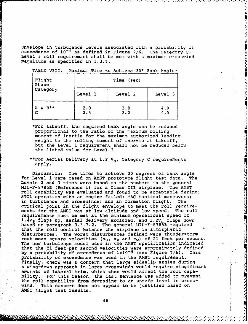
Envelope in turbulence levels associated with a probability ofexceedence of 10- 5 as defined in Figure 7/6. The Category C,Level 3 roll requirement shall be met with a maximum crosswindmagnitude as specified in 3.3.7.
TABLE VIII. Maximum Time to Achieve 300 Bank Angle*
Flight Time (sec)Phase __
: Category :Level 1 Level 2 Level 3
A & B** 2.0 3.0 4.0C 2.5 3.2 4.0
*For takeoff, the required bank angle can be reducedproportional to the ratio of the maximum rollingmoment of inertia for the maximum authorized landingweight to the rolling moment of inertia at takeoff,but the Level 1 requirement shall not be reduced belowthe listed value for Level 3.
" For Aerial Delivery at 1.2 Vs , Category C requirements
apply.
Discussion: The times to achieve 30 degrees of bank anglefor Level 1 were based on AMST prototype flight test data. TheLevels 2 and 3 times were based on the numbers in the generalMIL-F-8785B (Reference 1) for a Class III airplane. The AMSTroll capability was evaluated and found to be acceptable during:
STOL operation with an engine failed; MAC tactical maneuvers;in turbulence and crosswinds; and in formation flight. Thecritical point in the flight envelope to meet the roll require-ments for the AMST was at low altitude and low speed. The rollrequirements must be met at the minimum operational speed of1.4V s flaps up, aerial delivery excluded, and 1.2V flaps downbased on paragraph 3.1.7.2. The general TIL-F-8785B requiredthat the roll control balance the airplane in atmosphericdisturbances. The worst disturbances defined were thunderstormroot mean square velocities (au, Ov ani . w ) of 21 feet per second.The new turbulence model used in the AMST specification indicatedthat the 21 feet per second velocities were approximately definedby a prbbability 6f exceedence of l2 -.0 (see Figure 7/6). Thisprobability of exceedence was used in the AMST requirement.Finally, there wts a concern that large sideslip angles duringa wi.ng-down approach in large crosswinds would require singificant.axurntc of lateral trim, which then would affect the roll capa-bility. For this reason, the last sentence was added to preventthe roll capability from degrading to an unsafe level in cross-wind. This concern does not appear to be justified based onAMST flight test results.
46
* -I I i
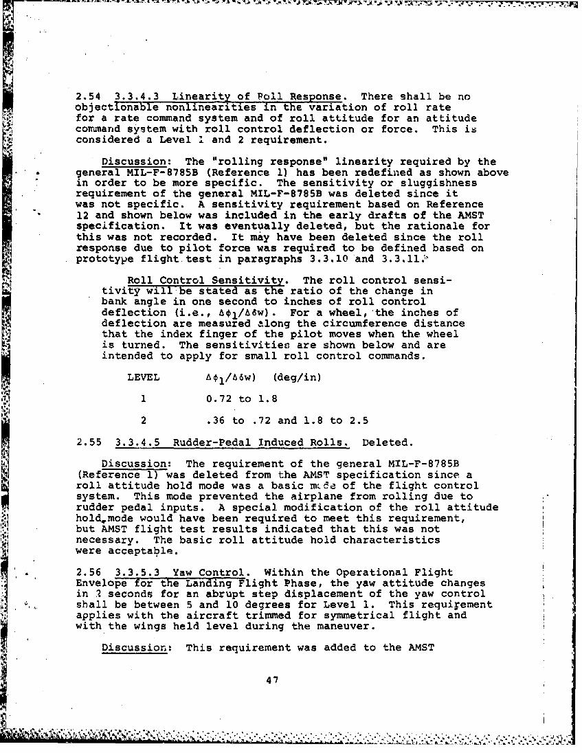
II 2.54 3.3.4.3 Linearity of Poll Response. There shall be noobjectionable nonlinearities in the variation of roll ratefor a rate command system and of roll attitude for an attitudecormand system with roll control deflection or force. This isconsidered a Level ' and 2 requirement.
Discussion: The "rolling response" linearity required by thegeneral MIL-F-8785B (Reference 1) has been redefined as shown abovein order to be more specific. The sensitivity or sluggishnessrequirement of the general MIL-F-8785B was deleted since itwas not specific. A sensitivity requirement based on Reference12 and shown below was included in the early drafts of the AMSTspecification. It was eventually deleted, but the rationale forthis was not recorded. It may have been deleted since the rollresponse due to pilot force was required to be defined based onprototype flight test in paragraphs 3.3.10 and 3.3.11.",
Roll Control Sensitivity. The roll control sensi-tivity will be stated as the ratio of the change inbank angle in one second to inches of roll controldeflection (i.e., q1/Aaw). For a wheel, the inches ofdeflection are measured along the circumference distancethat the index finger of the pilot moves when the wheel
is turned. The sensitivities are shown below and areintended to apply for small roll control commands.
LEVEL Aol/A6w) (deg/in)
1 0.72 to 1.8
2 .36 to .72 and 1.8 to 2.5
2.55 3.3.4.5 Rudder-Pedal Induced Rolls. Deleted.
Discussion: The requirement of the general MIL-F-8785B(Reference 1) was deleted from the AMST specification since aroll attitude hold mode was a basic m e of the flight controlsystem. This mode prevented the airplane from rolling due torudder pedal inputs. A special modification of the roll attitudehold mode would have been required to meet this requirement,but AMST flight test results indicated that this was notnecessary. The basic roll attitude hold characteristicswere acceptable.
2.56 3.3.5.3 Yaw Control. Within the Operational FlightEnvelope for the Landing Flight Phase, the yaw attitude changesin I seconds for an abrupt step displacement of the yaw controli 0 shall be between 5 and 10 degrees for Level 1. This requirementapplies with the aircraft trimmed for symmetrical flight andwith the wings held level during the maneuver.
Discussion: This requirement was added to the AMST
4.7
'IN.'.,
specification to insure adequate yaw control to decrab theairplane during landings in crosswinds of up to 30 knots. Therequirement was initially based on work reported in Reference 7,but the final numbers were based on acceptable AMST flighttest results and contractor comments.
2.5? 3.3.5.4 Yaw Control L(nearitx and Sensitivity. Thereshall be no objectionable nonlinearities in the variation ofdirectional response with yaw control deflection or forces.There shall be no excessive sensitivity or sluggishness ofairplane yaw response due to rudder pedal deflection or forcethat would prevent such things as satisfactory turn coordination,decrab for touchdown in crosswind, or c&trol of engine failuretransients.
Discussion: This requirement was initially intended toaddress more specifically the yaw control linearity and sensi-tivity than paragraph 3.3.5 of the general specification (Refer-ference 1). Initial drafts of the AMST specification had aLevel 1 sensitivity requirement of 0.05 to" 0.10 rad/sec 2 due toa 1.0 inch r.dder pedal input. This sensitivity was based onReference 15. AMST flight test results indicated that for oneairplane, the yaw acceleration was lower than 0.05 rad/sec, yetthe yaw response was genereblly considered acceptable by thepilots. A qualitative sensitivity requirement as shown abovewas ev~ntually added since a good quantitative requirementcould :_)t be verified.
2.58 3.3.5.5 Heading Control. Within the Operational FlightEnvelope for Category C, the heading delay ,, shall be lessthan the values shown below:
LEVEL T,# sec
1 1.22 2.03 3.0
The aircraft shall be initially trimmed when the maneuver isbegun.0 An explanation of T is presented in 6.2.6.
Discussion: This requirement was added to ensure good Itransient turn coordination characteristics for the variousLevels. The requirement was based on Reference 12, which didriot provide much supporting data. The parameter T4 is theheading response time delay for a coimnanded step bank anglechange (see the Appendix, paragraph 6.2.6). This paragraph -was added to provide a quantitative assessment of turn coordi-nation since the general MIL-F-8785B (Reference 1) requirement3.3.2.4.1 was deleted for the reasons given in 2.49 above.
2.59 3.3.6 LaLera'.-Directional Characteristics in Steady
48
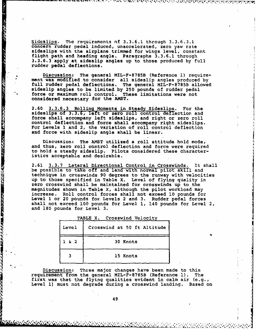
Sideslips. vhe requirements of 3.3.6.1 through 3.3.6.3.1concern rudder pedal induced, unaccelerated, zero yaw ratesideslips with the airplane trimmed for wings level, constantflight path and heading angle. Paragraphs 3.3.6.1 through3.3.6.3 apply at sideslip angles up to those produced by fullrudder pedal deflections.
Discussion: The general MIL-F-8785B (Reference 1) require-ment was modified to consider all sideslip angles produced byfull rudder pedal deflections. The general MIL-F-8785B allowedsideslip angles to be limited by 250 pounds of rudder pedalforce or maximum roll control. These limitations were notconsidered necessary for the AMST.
2.60 3.3.6.3 Rolling Moments in Steady Sideslips. For thesideslips of 3.3.6, left or zero roll control deflection andforce shall accompany left sideslips, and right or zero rollcontrol deflection and force shall accompany right sideslips.For Levels 1 and 2, the variation of roll control deflectionand force with sideslip angle shall be linear.
Discussion: The AMST utilized a roll attitude hold mode,and thus, zero roll control deflection and force were requiredto hold a steady sideslip. Pilots considered these character-istics acceptable and desirable.
2.61 3.3.7 Lateral Directional Control in Crosswinds. It shallbe possible to take off and land with normal plot skill andtechnique in crosswinds 90 degrees to the runway with velocitiesup to those specified in Table X. Level of flying quality inzero crosswind shall be maintained for crosswinds up to themagnitudes shown in Table X, although the pilot workload mayincrease. Roll control forces shall not exceed 10 pounds forLevel 1 or 20 pounds for Levels 2 and 3. Rudder pedal forcesshall not exceed 100 pounds for Level 1, 140 pounds for Level 2,and 180 pounds for Level 3.
TABLE X. Crosswind Velocity
Level Crosswind at 50 ft Altitude
1 & 2 30 Knots
3 15 Knots
Discussion: Three major changes have been made to thisrequirement from the general MIL-F-8785B (Reference 1). Thefirst was that the flying qualities evident in calm air (e.g.,Level 1) must not degrade during a crosswind landing. Based on
49
IL
-a. .AY w w . g * ~ ~ -
I-!
prototype flight test results, this was a realistic require-ment. The second item was that the crosswind magnitude wasquoted at 50 feet. This was important since winds vary as afunction of altitude due to shears, as defined in the Appendix,paragraph 3.7.1. Finally, the roll and rudder control forceswere based on AMST characteristics. Note that a crosswind of30 knots at STOL approach speeds results in a sideslip anglenear 20 degrees which may be the critical design case forrudder sizing and selection of the vertical tail airfoil toavoid fin stall.
2.62 3.3.7.1 Final Approach in Crosswinds. Deleted.
Discussion: This requirement was deleted since 3.3.7defined that the airplane must be capable of landing in cross-winds. The contractor should be allowed to determine whatrudder, aileron or landing gear capability is required toachieve the required crosswind landings.
2.63 3.3.9.1 Thrust Loss During Takeoff Run. It shall bepossible for the pilot to maintain control of an airplane onthe takeoff surface following sudden loss of thrust from themost critical factor. Thereafter, it shall be possible toachieve and maintain a straight path on a concrete (hard)takeoff surface without a deviation of more than 30 feetfrom the path originally intended, with rudder pedal forcesnot exceeding 120 pounds. For the Tactical Mobility Missionrunway defined in paragraph 3.2.1.1 of the System Specifica-tion, deviation from the path originally intended shall notresult in the main landing gear tires extending beyond therunway edge, nor the rudder pedal forces to exceed 120 pounds.The deviations from the intended path shall be analyzed for asudden fuel cut-off to the critical engine, with a 1 secondtime delay between the time of the engine failure and the startof the pilot control input. Flight test results shall be usedto demonstrate that the deviations from the path intended areless than required above. The deviations measured from flighttest shall include a pilot delay time determined by adding thelargest flight test delay time plus an additional 0.2 secondsto account for normal pilot surprise. For the continued take-off, the allowable deviations shall not be exceeded when thrustis lost from the refusal speed (based on the shortest runwaydefined in the System Specification) to the maximum takeoffspeed, with takeoff thrust maintained on the operative engine(s),using only pitch, roll and yaw controls. No forward movementor pressure shall be applied to the control column. For theaborted takeoff, the allowable deviations shall not be exceeded *
at all speeds below the maximum takeoff speed. However,additional controls such as nosewheel steering and differentialbraking may be used. Automatic devices which normally operatein the event of a thrust failure may be used in either case.
50
&N% %
Discussion: Several changes were made to this requirementfrom the general MIL-F-8785B (Reference 1). The first was thatthe requirement addressed the 60 feet wide Tactical MobilityMission runway since the conventional 30 feet lateral deviationwould result in landing gear tires off the runway. Any futurerelease of the Proposal Instruction Package would further clarifythat none of the main landing gear tires could extend beyond theedge of the runway. Secondly, the critical test condition of asudden fuel cut-off to the engine was defined in order to simulatean engine failure due to rotor seizure or burst. Even though thesudden fuel cut-off would be used for analysis and test verifica-tion of this requirement, it was still intended that all criticalengine failure cases be analyzed. The wording of the Reference 1requirement was perhaps misleading as to which cases were to beanalyzed, and this should be corrected in any future revision ofthe requirement. Third, the 1 second pilot delay time was notconsidered reasonable by a contractor due to experience with FAAcertification of commercial airplanes. Since no firm historicalbasis could be determined, the measured pilot delay time wasallowed to show compliance with the requirement. A 0.2 secondsadditional time was defined to account for surprise, and wasbased on discussions with USAF Aeromedical Laboratory personnel.Finally, nose wheel steering was allowed for the continued take-off if the inputs were made through the rudder pedals. No for-ward movement or pressure on the control column was permitted
* to prevent an improvement of nose wheel steering characteristicsby increasing the normal force on the nose wheel. This was pro-hibited since on the soft Tactical Mobility Field, unacceptablerutting might be caused by this procedure.
2.64 3.3.9.2 Thrust Loss After Takeoff. For takeoff, itshall be possible without a manually commanded configurationchange to achieve constant flight path and heading anglefollowing sudden asymmetric loss of thrust at Service FlightEnvelope speeds from Vmin (TO) to Vmax (TO). Thereafter, itshall be possible to maintain constant flight path and headingangle throughout the climbout. The rudder pedal force shallnot exceed 120 pounds. Roll control 4crce shall not exceedthe Level 3 force limits specified in 3.3.4.2. The Category C,Level 3, roll requirement of 3.3.4 shall be met with takeoffthrist maintained on the operative engine(s) and trim at normal
S°.settings for takeoff with symmetric thrust. Automatic deviceswhich normally operate in the event of a thrust failure may beused, and the airplane may be banked up to 5 degrees in thedirection to assist control.
Discussion: This requirement was basically the same asthe general MIL-F-8785B (Reference 1). Automatic configura-
,.. tion'changes during takeoff were allowed since the pilotwould not have to monitor the change. The MIL-F-8785B 75Climit on lateral control for trimming an engine failure wasrevised to require that the AMST be capable of at leastCategory C, Level 3 roll performance. This change wasmade since the 25% margin on lateral control was to provide
51
roll capability, and the AMST requirement defines specificallywhat capability was required. The AMST may also be banked upto 5 degrees in any direction to assist control in order torelieve lateral or directional control requirements.
2.65 3.3.10 Roll Attitude Command. For a roll attitudecommand mode, the roll attitude of the aircraft shall be pro-portional to a fixed roll control displacement from the rollcontrol trim position. Right roll control displacement and forceshall cause a positive increase in bank angle, and a left controldisplacement and forca shall cause a decrease in positive bankangle.' When the roll control is displaced in either directionand then released, the aircraft shall return to the initiallyreferenced roll attitude. The command roll attitude changeversus time shall be smooth, and the desired performance (i.e.,
overshoot, time history envelopes, etc.) defined by thecontractor. The limits on the change in roll attitude to thepilot's roll control force shall be defined by the contractorbased on prototype flight test results.3.3.11 Roll Rate Command Mode. For a roll rate command mode,the roll rate of the airplanishall be proportional to a fixedroll control displacement from the roll control trim position.Right roll control displacement and force shall cause a rightwing down roll rate, and a left roll control displacement andforce shall pause a left wing down roll rate. The commandedroll rate time history shall be smooth, and the desired per-formance (i.e., overshoot, time history envelopes, etc.)defined by the contractor. The limits on the commanded rollrate to the pilot roll control force shall be defined by thecontractor based on prototype flight test results.3.3.12 Roll Attitude Hold Mode. For a roll attitude holdmode, the referenced roll attitude shall be maintained insmooth air with a static accuracy of +1.0 degree. RMSattitude deviations shall not exceed T0 degrees in roll attitudein the following atmospheric environment:
Low Altitude - 25 kt total wind using 3.7.1 with aroughness length of 0.15 and corres-
* ponding turbulence as defined in para-graph 3.7.2.2.
High Altitude - Use turbulence levels associated witha probability of exceedence of 10-2 asdefined in Figure 7/6.
Accuracy requirements shall be achieved and maintained within3 seconds for a 5 degree attitude disturbance due to gust. .
Discussion: The discussion of 2.39 applies to the aboveparagraphs 3.3.10 and 3.3.11. The discussion for 2.40 explainswhere the turbulence magnitudes of paragraph 3.3.12 originated.The roll attitude requirement was based on paragraph 3.1.2.1
52
of Reference 2.
2.66 3.4.1 Dangerous Flight Conditions. Dangerous conditionsmay exist where the airplane should not be flown. Whenapproaching these flight conditions, it shall be possible byclearly discernible means for the pilot to recognize theimpending dangers and take preventive action.
Discussion: Procuring activity approval of warning indica-tions and devices to prevent entry into dangerous conditionswas deleted from the general MIL-F-8785B (Reference 1) require-ment. A procuring activity management directive was to deletesuch references. The reason for this was that if the procuringactivity approved a warning or preventative device and thenthe system did not perform satisfactorily in flight, thecontractor might pot be contractually responsible for correctingthe system. The preliminary activity approval would haveindicated that the system satisfied the contractual require-ments. The contractor is solely responsible for providingadequate warning as the pilot approaches dangerous conditions.These same comments apply to paragraph 3.4.1.2
2.67 3.4.2.1 Stalls. Stall usually is a phenomenon caused Iby airflow separation induced by high angle of attack, andfor the C-lXA, a reduction in thrust; it may also be definedby some limit on usable angle of attack (3.1.9.2). The stallrequirements apply for all Airplane Normal States in straightunaccelerated flight and in turns and pull-ups with attainablenormal acceleration up to nL . The pilot shall be warned whenFailure States (other than Special Failure States) exist thataffect stall characteristics. The pilot shall be able tosafely terminate or complete the flight phase that was inprogress at the time of the failure.
Discussion: References to paragraphs 6.2.2 and 6.2.5 inthe general MIL-F-8785B (Reference 1) 'ere deleted since thestall speee definition was moved into Section 3 of the AMSTspecification, paragraph 3.1.9.2. Stall speed was defined inthe zjain body of the specification for added emphasis. TheAMST requirement also recognized that for a STOL airplane,stall is a function of thrust setting. The last phrase ofthe general MIL-F-8785B paragraph was deleted since it wasargued that it was too general and unrealistic to require that
* all stall requirements be met with any failure state thataffects stall characteristics. For example, during unaccel-erated stalls with asymmetric flaps or slats the airplanewould not have been allowed to roll off more than 20 degrees.
2.68 3.4.2.1.1 Stall Approach. The stall approach shall beaccompanied by an easily perceptible warning. Acceptable
53
r ....
stall warning for all unaccelerated and accelerated stallsconsists of shaking of the cockpit controls, buffeting orshaking of the airplane, or a combination of both. The onsetof this warning shall occur within the ranges specified in3.4.2.1.1.1, but not within the Operational Flight Envelope.The warning shall continue until the angle of attack is reducedto a value less than that for warning onset. At all angles ofattack up to the stall, the cockpit controls shall remaineffective in their normal sense, and small control inputs shallnot result in departure from a controlled flight. Prior to thestall, uncommanded oscillations shall not be objectionable tothe pilot.3.4.2.1.1.1 Warning Speed for Stalls at 1S Normal to theFlight Path. Warning onset for stalls (3.1.9.2) at Ig normalto the flight path, shall occur between the following limitswhen the stall is approached gradually:
maximumFlight Phase Minimum Speed for Onset Speed for Onset
Approach Higher of 1.05Vs or H.igher-of 1.10VS orVS + 5 knots Vs + 10 knots
All Other Higher of 1.05V S or Higher of 1.15VS or
VS + 5 knots VS + 15 knots
3.4.2.1.1.2 Warning Range for Accelerated Stalls. Deleted.
Discussion: Paragraphs 3.4.2.1.1, 3.4.2.1.1.1 and3.4.2.1.1.2of the general MIL-F-8785B (Reference 1) weremodified as shown above. Both unaccelerated and acceleratedstalls were addressed in 3.4.2.1.1 since the same warning andcontrol characteristics were desired for both types of stalls.The warning range for accelerated stalls (3.4.2.1.1.2) wasdeleted since little difference was seen in the lift coefficientmargin provided by 3.4.2.1.1.1 or 3.4.2.1.1.2.
2.69 3.4.2.1.2 Stall Characteristics. In the unacceleratedstalls of 3.4.2.1 the airplane shall not exhibit rolling,yawing, or pitching at the stall which cannot be controlled tostay within 20 degrees. It is desired that no pitch-uptendencies occur in unaccelerated or accelerated stalls. Inunaccelerated stalls, mild nose-up pitch motion may be accept-able if no dangerous, unrecoverable, or objectionable flightconditions result. A mild nose-up tendency may be acceptablein accelerated stalls if the operational effectiveness of theairplane is not compromised and:
a. The airplane has adequate stall warning..
b. Pitch surface effectiveness is such that it is possibleto stop the pitch-up motion promptly and reduce the angle ofattack, and
54
i
c. At no point during the stall, stall approach, orrecovery does any portion of the airplane exceed structurallimit loads,
These requirements apply for all stalls, including stallsentered abruptly.
Discussion: The pitching motion discussed in the firstsentence of this paragraph should have been clarified as onlyin a downward direction, as was done in the general MIL-F-8785B(Reference 1). The general MIL-F-8785B requirement also didnot allow elevator control force reversal, but it was allowedin the AMST specification.
2.70 3.4.2.1.3 Stall Prevention and Recovery. It shall bepossible to prevent the stall by moderate use of the pitchor throttle control at the onset of the stall warning. Itshall be possible to recover from a stall by simple use of thepitch, roll, and yaw controls with cockpit control forces notto exceed those of 3.4.5.1, and to regain level flight with-out excessive loss of altitude or buildup of speed. Throttlesmay be changed to aid stpll recovery. In the straight flightstalls of 3.4.2.1, with zhe airplane trimmed at an airspeednot greater than 1.4 VS , and with a speed reduction rate ofat least 4.0 knots per second, the pitch control power shallbe sufficien,. to recover from any attainable angle of attack.
Discussion: The above requirement allows throttles to beused to prevent stall or for stall recovery, since with a STOLairplane this may be the most effective method. A speedreduction rate of 4.0 knots per second was defined in orderto be specific even though this was not defined in the generalMIL-F-8785B (Reference 1). This rate was taken from theoriginal issue of the flying qualities specification, MIL-F-8785B, dated 7 August 1969.
2.71 3.4.2.2.2 Recovery From Post-Stall Gyrations and Spins.The airplane must be readily recoverable from all attainableattitudes and motions. The post-stall characteristics shallbe determined.
Discussion: The general MIL-F-8785B (Reference 1)required that the post-stall characteristics be determined byanalysis and model tests. The methods of determining thepost-stall characteristics were not defined in order not tospecify the techniques used to design an airplane. The speci-fication defines only what performance is required.
2.72 3.5 Characteristics of the Manual Flight Control
55
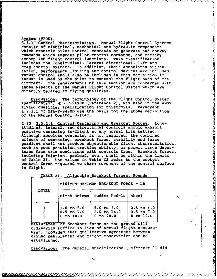
System (MFCS).
3.5.1 General Characteristics. Manual Flight Control Systemsconsist of electrical, mechanical and hydraulic componentswhich transmit pilot control commands or generate and conveycommands which augment pilot control commands, and therebyaccomplish flight control functions. This classificationincludes the longitudinal, lateral-directional, lift anddrag control systems. In addition, their associated aur.-in- qtation, performance limiting and control devices are included.Thrust control shall also be included in this definition ifthrust is used by the pilot to control the flight path of theaircraft. The requirements of this section are concerned withthose aspects of the Manual Flight Control System which aredirectly related to flying qualities.
Discussion: The terminology of the Flight Control Systemspecification, MIL-F-9490D (Reference 2), was used in the A-MSTflying qualities specification for uniformity. Paragraph1.2.1.1 of MIL-F-9490D was the basis for the above definitionof the Manual Control System.
2.73 3.5.2.1 Control Centering and Breakout Forces. Long-itudinal, lateral, and directional controls should exhibitpositive centering in-flight at any normal trim setting.Although absolute centering is not required, the combinedeffects of centering, breakout force, stability and forcegradient shall not produce objectionable flight characteristics,such as poor precision tracking ability, or permit large depar-tures from trim conditions with controls free. Breakout forces,including friction, preload, etc., shall be within the limitsof Table XI. The values in Table XI refer to the cockpitcontrol force required to start movement of the control surfacein flight.
TABLE XI. Allowable Breakout Forces, Pounds
MINIMUM-MAXIMUM BREAKOUT FORCE - LBLEVEL
Pitch Column Rudder Pedals Wheel
1 1.0 to 5.0 5.0 to 8.0 0.5 to 4.02 0.5 to 7.0 2.0 to 14.0 0.5 to 7.03 0 to 10.0 0 to 28.0 0 to 10.0
Measurement of breakout orce on the ground willordinarily suffice in lieu of actual flight measure-ment, provided that qualitative agreement betweenground meaLurement and flight observation can beestablished.
Discussion: The general specification (Reference 1) did
56
.4 '?,I ' _-" :.k)' . /.2 . .. -- -. ".. "*. -'. . . . .
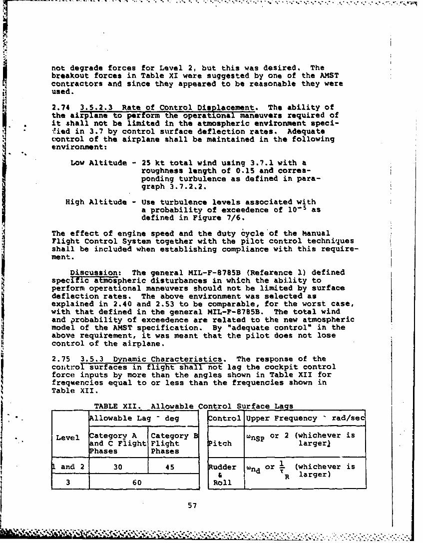
h
not degrade forces for Level 2, but this was desired. Thebreakout forces in Table XI were suggested by one of the AMSTcontractors and since they appeared to be reasonable they were
"i used.
2.74 3.5.2.3 Rate of Control Displacement. The ability ofthe airplane to perform the operational maneuvers required ofit shall not be limited in the atmospheric environment speci-'ied in 3.7 by control surface deflection rates. Adequate
control of the airplane shall be maintained in the followingenvironment:
Low Altitude - 25 kt total wind using 3.7.1 with aroughness length of 0.15 and corres-ponding turbulence as defined in para-graph 3.7.2.2.
High Altitude - Use turbulence levels associated withI a probability of exceedence of 10- 5 asdefined in Figure 7/6.
* The effect of engine speed and the duty cycle of the ManualFlight Control System together with the pilot control techniquesshall be included when establishing compliance with this require-ment.
Discussion: The general MIL-F-8785B (Reference 1) definedspecific atmospheric disturbances in which the ability toperform operational maneuvers should not be limited by surfacedeflection rates. The above environment was selected asexplained in 2.40 and 2.53 to be comparable, for the worst case,with that defined in the general MIL-F-8785B. The total windand probability of exceedence are related to the new atmosphericmodel of the AMST specification. By "adequate control" in theabove requirement, it was meant that the pilot does not lose
~control of the airplane.
2.75 3.5.3 Dynamic Characteristics. The response of the
conrol surfaces in flight shall not lag the cockpit controlforce inputs by more than the angles shown in Table XII forfrequencies equal to or less than the frequencies shown inTable XII.
TABLE XII. Allowable Control Surface Lags
Allowable Lag - deg Control Upper Frequency - rad/sec
Level Category A Category B Wnsp or 2 (whichever isand C Flight Flight Pitch larger)Phases Phases
1 and 2 30 45 Rudder wnd or (whichever is& TR larger)
3 60 Roll
57
Discussion: The upper frequency for pitch was furtherdefined as two radians/second based on discussions with NASAAmes Research Center personnel. This was done since the STOL air-plane my have very low short period natural frequencies.However, the flight control system should still have goodresponse characteristics up to at least two radians/second.
2.76 3.5.3.2 Damping. All control system oscillations shallbe well dantped (see paragraph 3.2.2.1.2) unless they are of 7such an anhplitude, frequency, and phasing that they do not
i reult in objectionableioscillations of the cockpit controlsor the airtrame during abrupt maneuvers and during flight inatm6splheric environments up to the following:
Low Altitude - 25 kt total wind using 3.7.l'with a rough-ness lenath of 0.15 and corresponding tur-bulence as defined in paragraph 3.7.2.2.
Hig- Altitude - Use turbulence levels associated with aprobability of exceedence of 10- 5 asdefined in Figure 7/6.
Discussion: See discussion of 2.74.
2.77' 3.5.4.1 Performance ofAgumentation Systems. Perform-,ance degradation of augmentation systems caused by atmosphericdisturbances and by structural vibrations shall ba considered.
Discussion: The general MIt-F-8785B (Reference 1) definesspecific atmospheric environments in which to consider perform-ance degradations of the augnentation. The above requirementddleted specific reference .to al*ospheric environments sincethey had been addressed in the fT.Jght control system performancerequirements of 3.5.2.3, 3.5.3.2 and 3.5.4.2. This requirementcould have been deleted since it added nothing to what had beenrequired by 3.5.2.3, 3.5.3.2 and 3.5.4.2.
2.78 3.5.4.2 Satnration of Augmentation Systems. Limits onthe authority of augmentation systems or saturation of equip-ment shall not result in objectionable flying qualities. Inparticular, this'requirement shall be met during rapid largeamplitude maneuvers,, during operation near VS , and during
flight in the atmospheric environment of paragraph 3.7.Saturation shall not degrade control below an adequate levelfur the following atmospheric environment:
Low Altit,.de - 25 kt total wind using 3.7.1 with a rough- F
ness length of 0.15 and corresponding tur-bulence as defined in paragraph 3.7.2.2.
58
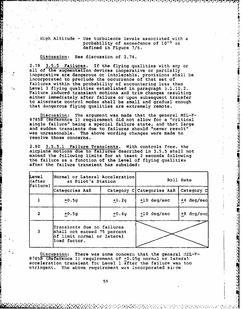
..Hith Altitude - Use turbulence levels associated with aprobability of exceedence of 10- 5 asdefined in Figure 7/6.
Discussion: See discussion of 2.74.
2.79 3.5.5 Failures. If the flying qualities with any orall of the augmentation devices inoperative or partiallyinoperative are dangerous or intolerable, provisions shall beincorporated to preclude the occurrence of that set offailures within the probability of encountering less thanLevel 3 flying qualities established in paragraph 3.1.10.2.Failure induced transient motions and trim changes resultingeither immediately after failure or upon subsequent transferto alternate control modes shall be small and gradual enoughthat dangerous flying qualities are extremely remote.
Discussion: The argument was made that the general MIL-F-8785B (Reference 1) requirement did not allow for a "criticalsingle failure" being a special failure state, and that largeand sudden transients due to failures should "never result"was unreasonable. The above wording changes were made toresolve those concerns.
2.80 3.5.5.1 Failure Transients. With controls free, theairplane motions due to failures described in 3.5.5 shall notexceed the following limits for at least 2 seconds followingthe failure as a function of the Level of flying qualitiesafter the failure transient has subsided:
Level Normal or Lateral Acceleration
(after at Pilot's Station Roll Ratefailure)
Categories A&B Category C Categories A&B Category C
1 +0.5g +0.2g +10 deg/sec +4 deg/sec
2 +0.5g +0. 4q +I0 deg/sec +8 deg/sec
Transients due to failures3 shall not exceed 75 percent
of limit normal or lateralload factor.
Discussion: There was some concern that the general IIL-F-8785B (Reference 1) requirement of +0.05g normal or lateralacceleration transient for Level 1 after the failure was toostringent. The above requirement wes incorporated sii'ce
59
Reference 14 suggested a relaxation in the requirement ifthe cost and complexity of the flight control rystem could notbe justified, and since it was compatible with paragraph3.1.3.3.4 of the Flight Control System specification (Reference2). Reference 2 was also the basis for the Levels 2 and 3,Categories A and B requirements. The AMST specification addressedCategory C separately since the failure transient values suggestedin references 1 and 2 were considered excessive for Category C.The values stated for Category C were arrived at mutually by theprocuring activity and an AMST contractor based on engineeringjudgement.
2.81 3.5.6.1 Transients. With controls free, the transientsresulting from the situations descrihed in 3.5.6 shall notexceed the following limits for at least 2 seconds followingthe transfer:
Within the Operational .0.05g nomai or lateral acceler-
Flight Envelope ation at the pilot's station and+1 degree per second roll.
Within the Service +0.5g normal or lateral acceler-Flight Envelope ition at the pilot's station or
+5 degrees per second roll.These requirements apply only for Airplane Normal states.
Discussion: The requirement within the Service Flight Enve-lope was 7edi1fied to address normal and lateral accelerations. :The service flight envelope sideslip and structural limits ofthe general MIL-F-8785B (Reference 1) were addressed by thelateral acceleration limit.
2.82 3.6.3.1 Pitch Trim Changes. The pitch trim changescaused by operation of t Manu-aT Flight Control System shallnot be so large that a peak pitch control force in excess of20 pounds is required under conditions representative ofoperational procedures. Generally, the coiditions listed inTable XIII will suffice for determiniation of compliance withthis requirement. With the airplane trimmed for each specificInitial condition, the peak force required to maintain thespecified parameter constant following the specified configura-tion change shall not exceed 20 pounds for at least 5 secondsfollowing the completion of the pilot action initiating theconfiguration change. The magnitude and rate of trim changesubsequent to this time period shall be such that the forcesare easily trimmed by use of the normal trimming devices. Theabove requirements define Level 1. For Levels 2 and 3, theallowable forces are increased by 50 percent. If automatictrim devices are selectable by the pilot, they shall be inoper-able when showing compliance with this requirement.
60
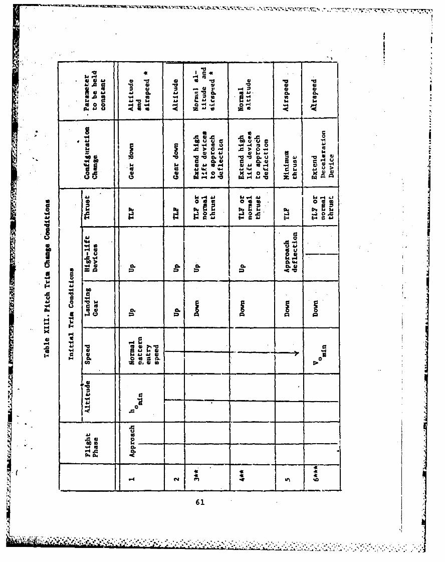
_ _ _ -~ 4t__ __
44 a ra .04Ai4 -0 $4 461 A3 u
"44 "4 cc 0 4 -4mX0 . 0 p "-P 0q
94 00 a LvaL06c0 AJ go -4 AU U M r4 P44)-
*co0. 410. %w %Wt t .-'00 0@ "4 0 0
16 03 .a..* *4 e 0
a Ig w~
U =
E-4 A
'-4c
661
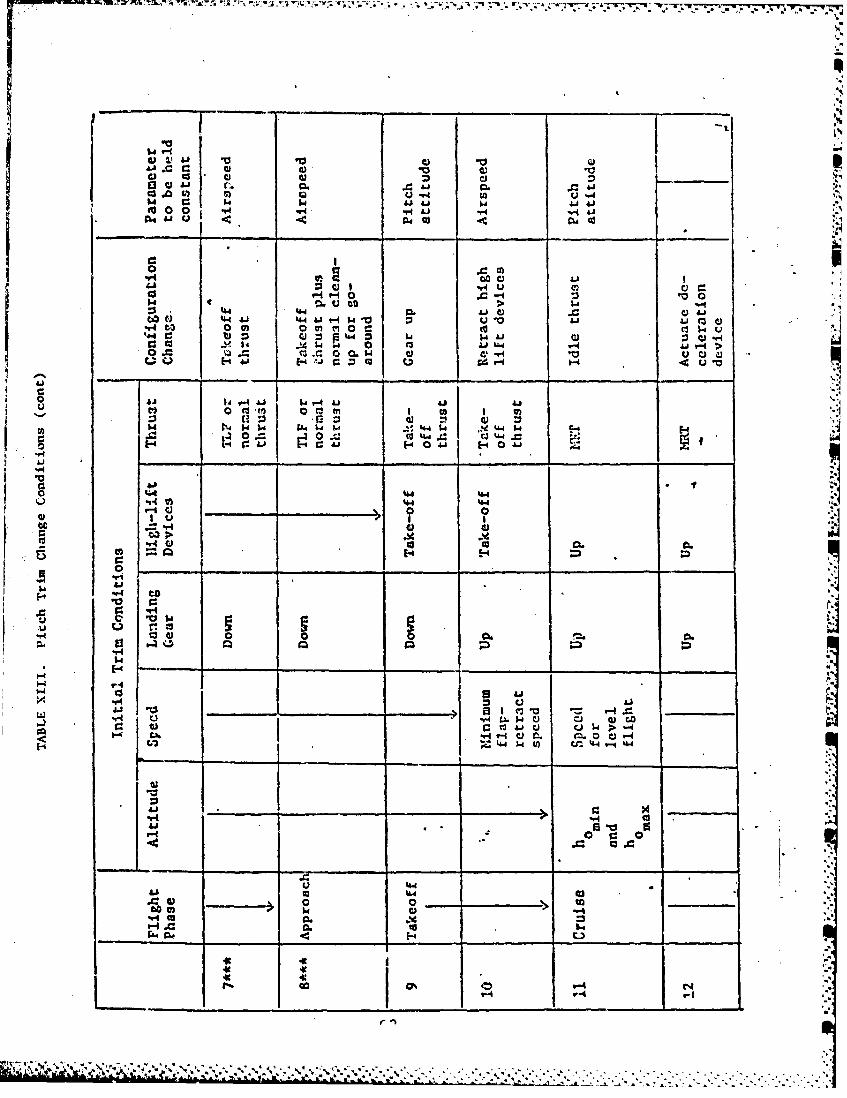
w r.I "4fa.C 0 0 A0'44A4 ad C1i C6 ._ __a
&A :. V4u r
to 0 ~ 0 0I d(
411 1- J C D Qi
54
w, 14$ 44.14 4 U
00 IUI
94CJ0 0l0.
.0 14 -4 =3
1.44
r- 94
V4 n._ II a=]~ I~2 0 n a_ ___=
-H Lu)-a U 4) C.0
44 W U4.4L
441.. 0 w_
CO l 0_ _ _ _ _
go r-4 . 1
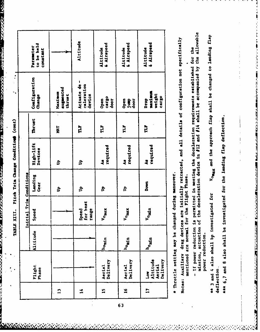
- 0.0~. m 4 A -
Aj 41 1-4 41w
614 V1 6
6161 661 616 U 1 j4.1.0~~ ~~ C4U .0 .r ~ .
,.. AJ4 -A~ to
4.5 0
ho 41 tto 64 u' 0 N Q
40 to6 6&J~4p I OW o 0 a1 4L
4.4 61 Q. 61
61V U.1 0.0 tov.
i C4 44
00 61cr0 ~
to :*y4 0r 0k '
0 4 ~1 "
p4 p4 IW'.O 4)
4V
0 04. .4
"4 v. 9s K p46
K 60 'a p0. W Ia61 U
444
416 1-6 041
41.
44 -0 V616161IA41 W-e V- -j u 41=6 1
5'~~~~~~9 Ow 41 w;< 7 . . . . . - ' - 5 ---
Discussion: Twenty pounds of trim force were allowedindependent of controller type since values up to this wereanticipated with certain configuration changes and wereconsidered to be acceptable for the AMST. Values significantlygreater than 20 pounds were experienced during the prototypeflight testing and were not considered acceptable.Table XIII of the AMST specification was, in general, the sameas Table XIV of the general MIL-F-8785B (Reference 1).Numbers 1 and 3 of Table XIII allowed thrust to be varied sincethat may be the manner in which the altitude is controlled nearor on the backside of the power required curve. Numbers 3, 4,6, 7, and 8 were expanded to investigate landing flaps sincelarge trim forces may be associated with this configurationchange. Numbers 3, 4, 6, 7, and 8 also recognized that suffi-cient thrust may not be available to fly constant altitude withthe STOL landing flaps by addressing normal thrust as well asTLF. Number 14 was changed to altitude held constant toinvestigate the case where speed brakes are used to slow downduring aerial refueling. A similar case should have beenadded to evaluate the use of drag devices to descend in altitudeat constant speed. This maneuver was used tactically to quicklyobtain approach conditions. Numbers 15, 16, and 17 wereadded to evaluate particular AMST mission requirements.
2.83 3.6.5 Delete.
Discussion: This paragraph from the general MIL-F-8785B(Reference 1) was changed to 3.2.3.2.3 in the AMST specificationsince it was more appropriate in the longitudinal control sectionfor a STOL airplane.
2.84 3.7 Atmospheric Environment. This section presents then.-an wind and turbulence models to be used for flight controlsystem design. Sections 3.7.1 and 3.7.2 present models forcontinuous wind phenomena, mean wind and turbulence, andSection 3.7.3 presents the discrete gust model. For the contin-uous wind phenomena, wind and turbulence levels are defined bya probability of exceedence and altitude. For the low altitudemodels (below about 3,000 feet), the probability of exceedencedefines a mean wind profile. This wind level then defines theturbulence levels. For high altitude operation (above about3,000 feet), mean winds are not important for handling qualitiesso exceedence probabilities directly define turbulence levelsand a mean wind model is not used. The continuous wind phe-nomena are generated in an earth-reference axis system, andtransformed to the body-axis system. The calculation of airspeedis then:
64
-,- * *
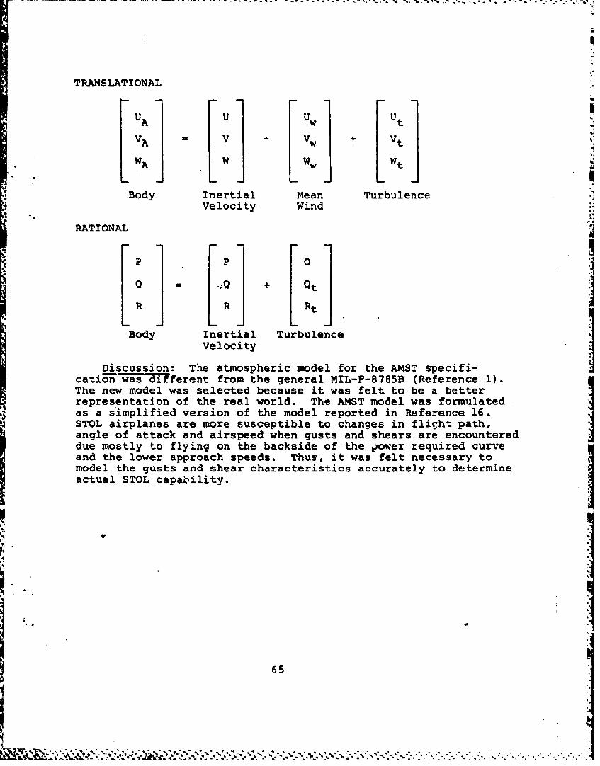
TRANSLATIONAL
U U Uw UtvA - v vw tVA V + V + Vt
WA Ww wt
Body Inertial Mean TurbulenceVelocity Wind
RATIONAL
P P 0
0 -- . + Qt.j
R R Rt
Body Inertial TurbulenceVelocity
Discussion: The atmospheric model for the AMST specifi-cation was different from the general MIL-F-8785B (Reference 1).The new model was selected because it was felt to be a betterrepresentation of the real world. The AMST model was formulatedas a simplified version of the model reported in Reference 16.STOL airplanes are more susceptible to changes in flight path,angle of attack and airspeed when gusts and shears are encountereddue mostly to flying on the backside of the power required curve
and the lower approach speeds. Thus, it was felt necessary tomodel the gusts and shear characteristics accurately to determineactual STOL capability.
65
I
SECTION 3
CONCLUSIONS AND RECO4MENDATIONS
The conclusions and recommendations based on the develop-ment of flying qualities requirements for a production AdvancedMedium STOL Transport (AMSTi are presented below:
1. Flying qualities requirements were developed thataddressed the major concerns of both STOL and conventionalflight regions.
2. Requirements for acceptable open loop dynamics withthe stability and command augmentation operating were felt tobe weak and in need of further development, particularly in thelongitudinal axis. The proposed criterion in Reference 9should be applied to airplanes with AMST characteristics todetermine if it could successfully determine flying qualitiesfor that type of airplane. This criterion was developed toaddress higher order longitudinal flight control systems offighter airplanes.
3. Requirements that address the combination of a ratecommand or attitude command system with attitude hold shouldbe developed. The AMST flying qualities requirements addressedeach of these modes individually; however, the pilot normallyused the combination to control the airplane throughout theflight envelope. Acceptable flying qualities may not resultfrom the combination even though the command and attitude holdmodes meet their respective requirements.
4. Autcmatic reduction of control forces during mildmaneuvering, such as normal terminal area operations, appearedto be acceptable. However, during tactical maneuvering nearthe airplane structural limits, the automatic reduction ofcontrol forces may be unacceptable due to the lack of stickforce cues to warn of overstressing the airplane. This concernwas not adequately addressed in the requirements presented inthis report. It is recommended that stick forces not beallowed to be reduced to zero during tactical maneuvering untiladditional development work has been completed in this area.
5. The frontside or backside control technique (i.e.,pitch column for flight path control and throttle for airspeedcontrol, or vice versa) was acceptable to the AMST prototypepilots during STOL landing. Frontside control characteristicswere provided artificially through augmentation. The effectsof flight control system failures, particularly those thatresult in an unaugmented system, must be considered early inthe design to insure good mission reliability during anticipatedoperational conditions.
66
s VI
6. Sizing the engine must take into account the flightpath change capability required to track a glideslope in windshears with an engine failed. The AMST requirements consideredtwo different engine out situations; one where the enginefailed below the go-around decision height and the other wherethe failure occurred above the decision height. A failureoccurring above the go-around decision height was the criticalcase since higher wind magnitudes were considered. A decisionmust be made early in the STOL airplane development whether ornot a STOL landing will be completed if an engine is known tobe failed above the decision height, since this capability willhave a direct impact on engine sizing and cost. Further,additional research on the flight path capability required forSTOL landing must be conducted to provide more supportingdata for this critical area.
7. As indicated in 6 above, the wind mxignitudes and thecorresponding wind shear profiles significantly affect STOLflight path tracking capability. The winds chosen for theAMST were based mostly on engineering judgment of what theoperational situations would be like. It is likely that forother STOL airplane designs the wind magnitudes should bedecreased or increased depending upon the anticipatedoperational conditions. Flight control system design, espe-cially airspeed hold systems used during STOL landings, mustconsider the effects of wind shear profiles.
8. Many of the AMST requirements for the STOL flighti.. region were based on limited flight test experience. The
requirements should be revised, if necessary, as more flighttest experience is gained.
67
p
APPENDIX
FLYING QUALITIES FOR C-lXA AIRFLANES
This appendix c-ontains a complete set of the flying
qualities requirements for & production AMST, and was released
as part of the USAF Proposal Instruction Package in 1977.
aa
| 68
gwfA
III. FLYING QUALITIES FOR C-1XA AIRPLANES
1. SCOPE AND CLASSIFICATIONS
1.1 Scope. This document contains the requirements for the flyingqualities of the C-1XA.
1.2 AD-lication., These requirements shall be applied to assure thatno limitations on flight safety or on the capability to perform intendedmissions will result from deficiencies in flying qualities.
1.3 Classification of Airplanes. Not required.
1.4 Fliaht Phase Categories. The Flight Phases have been combined intothree categories which are referred to in the requirement statements,These Flight Phases shall be considered in the context of total missionsso that there will be no gap between successive Phases of any flight andso that transition will be smooth. In certain cases, requirements aredirected at specific Flight Phases identified in the requirement. Whenno Flight Phase or Category is stated in a requirement, that requirementshall apply to all three categories. Flight Phases descriptive of theC-iZA are:
Nonterminal Flight Phases:
Category A - Those nonterminal Flight Phases that require rapidmaneuvering, precision tracking, or precise flight-path control. Included in this Category are:I a. Low Altitude Aerial Delivery (LA).
b. Close Formation Flying (FF).c. Contour Flying (CF)d. Tn-Flight Refueling (receiver) (RR).
Contour flying involves flight at altitudes up to4P 1000 feet above ground level to avoid ground fire
or detection.
Category B - Those nonterminal Fliglt Phases that are normallyaccomplished using gradual maneuvers and withoutprecision tracking, although accurate flight-pathcontrol may be required. Included in this Categoryare:
69
-I .. .= . -
i
a. Climb (CL) d. Descent (D)b. Cruise (CR) ** Deceleration (DE)c. Loiter (LO) f. Aerial Delivery (AD)
Terminal Flight Phases:
Category C - Terminal Flight Phases normally requiring accurateflight path control.
a. Assault Takeoff (AT) e. Assault Landing (AL)b. Takeoff (TO) f. Landing (L)c. Approach (PA)d. Go-around (GA)
The word assault in this document is meant to signify that enginefailed safety margins are not provided.
1.5 Levels of FlyinR Qualities. Where possible, the requirements ofsection 3 have been stated in terms of three values of the stability orcontrol parameter being specified. Each value is a minimum conditionto meet one of three Levels of acceptability related to the ability tocomplete the operational missions for which the airplane is designed.The Levels are:
Level 1 Flying qualities clearly adequate for the mission Flight PhaseLevel 2 Flying qualities adequate to accomplish the mission Flight
Phase, but some increase in pilot workload or degradationin mission effectiveness, or both exists.
Level 3 Flying qualities such that the airplane can be controlledsafely, but pilot workload is excessive or mission effec-tiveness is inadequate, or both. Category A Flight Phasescan be terminated safely, and Category B and C FlightPhases can be completed safely.
2. A&ylicable Documents. Deleted.
3. Requirements.
3.1 General Requirements.
3.1.1 Operational Missions. The flying qualities throughout the operationalmissions defined in Appendix 10 of the System Specification shall meetthe requirements of this document. t
3.1.2 Loadings. The contractor shall define the envelopesof center of gravity and corresponding weights that can exist. These. "*
70
envelopes shall show the probable bounds of center of gravity that canexist for each rlikht Phase. These envelopes shall include the mostforward and aft center of gravity positions. In addition, the contractor
shall determine the maximu center of gravity excursions attainablethrough failures in svsteus or components, such as fuel sequenqing orhunp payloads, for each Flight Phase to be considered in the FailureStates of 3.1.6.2. Within these envelopes, including the excursi.scited above, this document shall apply. A number of critical design
"A loading envelopes shall be prepared within which the loadings for thevarious missions and Flight Phases fall.
3.1.3 Moments of Inertia. The contractor shall define the moments ofinertia associated with all loadings of 3.1.2. The requirements of thisdocumient shall apply for all mounts of inertia so defined.
3.1.4 External Stores. The requirements of this docunt shall applyfor all combinations of external stores used during the operational mis-sions. The effects of external stores on the weight, moments of inertia,Center of gravity position, and aerodynamic characteristics of the air-craft shall be determined for each miLssion FliAgt Phase. When the stores
contain expendable loads, the requirements of this document apply through-out the range of store loadings. In establishing external store combina-tions to be investigated, asymmetric as well as symnmtric combinationsshall be evaluated if these combinations are used during the operationalmissions.
3.1.5 Configurations. The requirements of this document shall applyfor all configurations required or encoutered in the applicable FlightPhases of 1.4. A (crew) selected configuration is defined by the positionsand adjustments of the various selectors and controls available to thecrew except for rudder, aileron, elevator, throttle and trim controls.Dire.. lift may be included in the configuration definition if it is nota third controller as defined in 3.2. The selected configurations tobe exained must consist of those required for performance and missionaccomplishment.
3.1.6 State of the Airplane. The State of :le airplane is defined bythe selected confilguration together with the functional status of eachof the airplane components or systems, thrust, weight, moments of inertia,and center of gravitv position. The mazimum/critical design weightsand the corresponding moents of inertia shall be used in defining theState of the airplane. The trim settings and the control positions ofthe rudder, aileron, elevator, and direct lift (when considered as athird controller) are not included in the definition of Airplane State.
71
-I -: . , - .- -: , " . . .. : . ... . .. , . . - . ----. .--_ . , ..-. ... .. , . .-, -..... .., . . - . _ . . . • ....... , -., , , . ,
.. ... . .. .. .. ... .,.
3.1.6.1 Airplane Normal States. The contractor shall define and tabulateall pertinent items to describe the Airplane Normal (no component orsystem failure) State(s) associated with each of the applicable FlightPhases. This tabulation shall be in the format and shall use the nomen-clature as shown in 6.2. CerLain items, such as weight, moments of inertia,center of gravity position, flap or thrust setting may vary continuouslyover a range of values during a Flight Phase. The contractor shall replacethis continuous variation by a limited number of values of the parameterin question which will be treated as specific states, and which includethe most critical - -s and the extremes encountered during the FlightPhase in question.
3.1.6.2 Airplane Failure States. The contractor shall define and tabulateall Airplane Failure States, which consist of failures of airplane com-ponents or systems that affect the Flying Qualities of the airplane.Failure States caused by more than three independent subsystem failuresnepd not be tabulated. Airplane Failure States shall reflect changes inairplane hardware or the rcsults of more detailed analyses. Exampleswould be Jammed surfaces, mechanical or electrica*l disconnects, one ormore channel of augmentation failed, and/or two hydraulic systems out.Other degradations or failure of airplane components for systems resultingfrom the first failure, must also be accounted for in determining the
total effects on aircraft control. More specific direction is given in3.1.10.2.
3.1.6.2.1 Airplane Special Failure States. Certain components, systems,or combinations thereof, may have extremely remote probability of failureduring a given mission. These failure probabilities may, in turn, be verydifficult to predict with any degree of accuracy. Special Failure Statesof th. type need not be considered in complying with the requircmentsof section 3 (except 3.1.10.2) if justification for considering theFailure States as special is submitted by the contractor. The Air-plane Special Failure States shall reflect changes in airplane hardwareor the results of more detailed analyses. Failures which have aprobability of occurrence less than ixlO -9 per mission may be con-sidered Special Failure States -ithout submittal to the procuring activity.
3.1.7 Operational Flight Envelopes. The Operational Flight Envelopesdefine the boundaries in terms of speed, alt.tude, and load factor withinwhich the airplane must be capable of operating in order to accomplishthe risnions of 3.1.1. These envelopes shall be defined for the acmospherictamperatures required by paragraph 3.2 of the System Specification andAppendix 50 of the System Specification. Envelopes for each applicableFlight Phase -hall be established by the contractor. The boundaries ofthe Operational Flight En elopes shall be as defined by paragraphs3.1.7.1, 3.1.7.2, 3.1.7.3, and 3.1.7.4.
7.
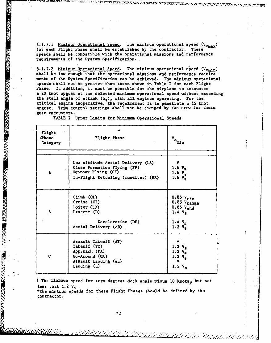
3.1.7.1 Maximum Operational Speed. The maximum operational speed (Vomax)for each Flight Phase shall be established by the contractor. Thesespeeds shall be compatible with the operational missions and performancerequirements of the System Specification.
3.1.7.2 Minimum Operational Speed. The minimum operational speed (Vomin)shall he low enough that the operational missions and performance require-ments of the System Specification can be achieved. The minimum operationalspeeds shall not be greater than those shown in Table I for each FlightPhase. In addition, it must be possible for the airplane to encountera 20 knot upgust at the selected minimum operational speed without exceedingthe stall angle of attack (as), with all engines operating. For thecritical engine inoperative, the requirement is to penetrate a 15 knotupgust. Trim control settings shall not be changed by the crew for thesegust encounters.
TABLE I Upper Limits for Minimum Operational Speeds
Flight,Phase Flight Phase VCategory .min
Low Altitude Aerial Delivery (LA) IClose Formation Flying (FF) 1.6 Vs
A Contour Flying (CF) 1.6 VsIn-Flight Refueling (receiver) (RR) 1.6 Vs
Climb (CL) 0.85 Vr/cCruise (CR) 0.85 VrangeLoiter (LO) 0.85 Vend
B Descent (D) 1.4 V5
Deceleration (DE) 1.4 VsAerial Delivery (AD) 1.2 V5
Assault Takeoff (AT) *Takeoff (TO) 1.2 VsApproach (PA) 1.2 Vs
C Go-Around (GA) 1.2 V5Assault Landing (AL) *Landing (L) 1.2 Vs
# The minimum speed for zero degrees deck angle minus 10 knots, but notless that 1.2 Vs
ij *The minimum speeds for these Flight Phases should be defined by thecontractor.
- .. 7
3.1.7.3 Maximum operational Altitude. The maximum operational altitudefor each Flight Phase shall be established by the contractor. Thesealtitudes shall be compatible with the operational missions and perform-ance requirements of the System Specification.
3.1.7.4 Operational Load Factors. The maximum (minimum) operationalload factor is the lowest (highest) algebraically of the following:
a. n - 2.0 (n - 0.5).b. The load factor at which stall warning occurs.
The maximum and minimum operational load factors for each Flight Phaseshall be established as a function of speed for several different altitudes.
3.1.8 Service Flight Envelopes. For each Airplane Normal State th,contractor shall establish Service Flight Envelopes showing combinationsof speed, altitude, and normal acceleration derived from airplane limitsas distinguished from mission requirements. These envelopes shall bedefined for the atmospheric temperatures required by paragraphs 3.2 ofthe System Specification and Appendix 50 of the System Specification.For each applicable Flight Phase and Airplane Normal State, the boundariesof the Service Flight Envelopes can be coincident with or lie outsidethe corresponding Operational Flight Envelope, but in no case shall theyfall inside those Operational boundaries. The boundaries of the ServiceFlight Envelopes shall be based on 3.1.8.1, 3.1.8.2, 3.1.8.3, and 3.1.8.4.
3.1.8.1 Maximum Service Speed. The maximum service speed, Vmax or Mmax,for each altitude shall be the same as the maximum operational speed. Anacceptable speed margin shall exist between the maximum service speedand the maximum permissible speed, with the high-lift devices stored, toallow for inadvertent overspeed conditions. When the high-lift devicesare extended, the maximum service speed may be the same as the maximumpermissible speed.
3.1.8.2 Minimum Service Speed. The minimum service speed, Vmin or Mmin,for each altitude is the highest of:
a. 1.1 Vb. V S + 10 knots equivalent airspeed.c. Stall warning speed defined by 3.4.2.1.1, for any thrust setting.d. A speed at which it is possible to achieve a constant heading
following a sudden asymntric loss of takeoff thrust from the most criticalfactor, and thereafter to maintain a constant beading. No changes in the
74
...........
':A " ~~~~~~~~~~~~~~~~~~~~~~~~~~.I. -". .... .' ... .... .. .... . ...-... , ." ... "-.,- . . . . .- ........ ......... . ... -....
pilot selected configuration are allowed to show compliance with thisrequirement. In addition, at this speed the roll control capability
shall provide at least 30 degrees bank angle change in 4 seconds. Theroll requirement shall be met for the steady state jymmetric thrustcondition, with takeoff thrust maintained on the operative engine(s),
'and trim at normal settings for symmetric thrust. The airplane may bebanked up to 5 degrees in a direction to assist control.
e. A speed limited by reducing visibility or an extreme pitch attitudethat would result in the tail or aft fuselage contacting the ground.
3.1.8.3 Maximum Service Altitude. The maximum service altitude, hmax,for a given speed is the maximum altitude at which a rate of climb of100 feet per minute can be maintained in unaccelerated flight with take-off thrust.
3.1.8.4 Service Load Factors. Maximum and minimum service load factors,n(+) (n(-)), shall be established as a function of speed for severalsignificant altitudes and weights. No consideration is given to the powerrequired to maintain flight at these g levels. The maximum (minimum)service load factor, when trimmed for ig flight at a particular speed andaltitude, is the lowest (highest) algebraically bf:
a. The positive structural limit load factor, or for negative loadfactor to zero g's.
b. The load factor corresponding to stall warning (3.4.2.1.1).
c. A safe margin below (above) the load factor at which intolerablebuffet or structural vibration is encountered.
3.1.9 Permissible Flight Envelopes. The Permissible Flight Envelopesencompass all regions in which operation of the airplane is possible.These are the boundaries of flight conditions outside the Service FlightEnvelope which the airplane is capable of safely encountering. ThePermissible Flight Envelopes define the bouriAries of these areas interms of speed, altitude, and load factor. 7nese envelopes shall bedefined for the atmospheric temperatures required by paragraph 3.2 of theSystem Specification and Appendix 50 of the System Specification.
3.1.9.1 Maximum Permissible Speed. The maximum permissible speed for
each altitude shall be the lowest:
-a. Limit speed based on structural considerations.
-74 b. Limit speed based on engine considerations.
*" c. The speed at which intolerable buffet or structural vibrations isencountered.
d. The speed at which the transonic Mach tuck is greater than allowedfor Level 3 of paragraph 3.2.1.1.1.
75
ON .........................................
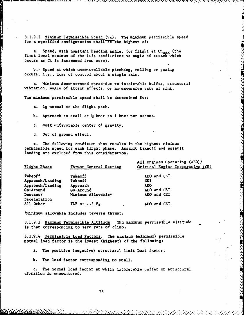
3.1.9.2 Minimum Permissible Speed (Vs). The minimum permissible speedfor a specified configuration shall-"-ethe highest of:
a. Speed, with constant heading angle, for flight at CLmax (thefirst local maximum of the lift coeff.Lcient vs angle of attack whichoccurs as CL is increased from zero).
b.. Speed at which uncontrollable pitching, rolling or yawingoccurs; i.e., loss of control about a single axis.
c. Minimum demonstrated speed-due to intolerable buffet, structural
vibration, angle of attack effects, or an excessive rate of sink.
The minimum permissible speed shall be determined for:
a. lg normal to the flight path.
b. Approach to stall at knot to I knot per second.
c. Most unfavorable center of gravity.
d. Out of ground effect.
e. The following condition that results in the highest minimumpermissible speed for each flight phase. Assault takeoff and assaultlanding are excluded from this consideration.
All Engines Operating (AEO)/
Flight Phase Thrust Control SettingEnginesne Inoerative (CE!
Takeoff Takeoff AEO and CEIApproach/Landing Takeoff CEIApproach/Landing Approach AEOGo-Around Go-Around AEO and CEIDescent/ Minimum Allowable* AEO and CEIDecelerationAll Other TLF at i.2 Vs AEO and CEI
*Minimum allowable includes reverse thrust.
3.1.9.3 Maximum Permissible Altitude. Th. maximum permissible altitudeis that corresponding to zero rate of climb.
3.1.9.4 Permissible Load Factors. The maximum (minlimum) permissiblenormal load factor is the lowest (highest) of the following:
a. The positive (negative) structural limit load factor.
b. The load factor corresponding to stall.
c. The normal load factor at which intolerale buffet or structuralvibration is encountered.
76
........................................

3.1.10 Applications of Level-. ],evals of flying qualities as indicatedIn 1.5 are employed in this document in realization of the possibilitythat the airplane may he required to operate under abnormal conditions.%uh ahnormalitle that may occur as a result or either flight outsidethe OperatIonal Flight Envelope or the failure of airplane components,or both, are permitted to comply with a degraded Level of flyingqualities as specified in 3.1.10.1 through 3.1.10.3.3.
3.1.10.1 Requirements for Airplane Normal States. The minimum requiredflying qualities for Airplane Normal States (3.1.6.1) are as shown inTable II.
TABLE II. Levels for Airplane Normal States
Within WthinOperational Flight Service Flight
Envelope Envelope
Level I Level 2
3.1.10.2 Requirements for Airplane Failure States. When Airplane FailureStates exist (3,1.6.2), a degradation in flying qualities is permitted.The contractor shall determine, based on the most accurate available data,the probability of occurrence of each Airplane Failure State per missionand the effect of the Failure State on the flying qualities within theOperational and Service Envelope. Specifically, the analysis shalladdress the following: (a) The 44m-. t - L Lti -. Ps- _p P " Arla'd 7"epProfile define'! in the System Specification, Appendix, Section 60, Table4-. " shall be used for this analysis. This mirsion scenario will be usedto determine how long specific aircraft systems are used per mission.(b) All of the various elements that can fail in many differtnt modesbut result in the same general airplane condition. shall be tabulatedunder one general failure state (e.g., pitch :,ugmentation failure, forcegradient reduction, one hydraulic system out, etc.). The probability ofencountering the general failure state shall be calculated as a functionof all the element failures. Once the effect of a general failure state
, "on handling qualities is determined (see part c), the probability cfencountering a particular Level of handling qualities is also known fora particular general failure state. (c) The effect of a general failure
77
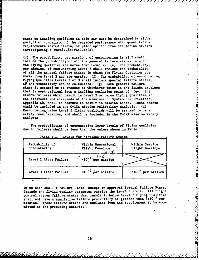
state on handling qualities in calm air must be determined by eitheranal7tical comparison of the degraded performance with quantitativerequirements stated herein, or pilot opinion from simulation studiesinvestigating a particular failure(s).
(d) The probability, per mission, of encountering Level 2 shall
includ the probability of all the general failure states in whichthe Flying Qualities are worse than-Level 2. (e) The probability,per mission, of encountering Level 3 shall include the probabilityof all the general failure states in which the Flying Qualities areworse than Level 3 and are-unsafe. (f) The probability of encounteringFlying Qualities Levels 2 or 3 shall include special failure states,
if the probability can be calculated. (g) Each general failurestate is assumed to be present at whichever point in the flight envelopethat is most critical from a handling qualities point of view. (h)Random failures which result in Level 3 or below flying qualities atthe altitudes and airspeeds of the missions of System Specification,Appendix 60, shall be assumed to result in mission abort.. These abortsshall be included in the C-IXA mission reliability'analysis. (i)Encountering below Level 3 flying qualitids will be assumed to be asafety consideration, and shall be included in the C-1XA mission safetyanalysis.
The probabilities of encountering lower Levels of flying qualitiesdue to failures shall be less than the values sbown in Table III.
TABLE III. Level for Airplane Failure States
Probability of Within Operational Within ServiceEncountering Flight Envelope Flight Envelope
Level 2 After Failure <10 per mission
Level 3 After Failure <10 - 4 per mission <10-2 per mission
In no case shall a Failure State, except an approved Special Failure State,degrade any flying quality parameter outside the Level 3 limit. All flightcontrol system failure states that result in below Level 3 Flying Qualitiesshall not have a cumulative failure probability of greater than 5x10- 7 permission. These failure states are excluded from the requirement to be sub-mitted to the procuring activity
78
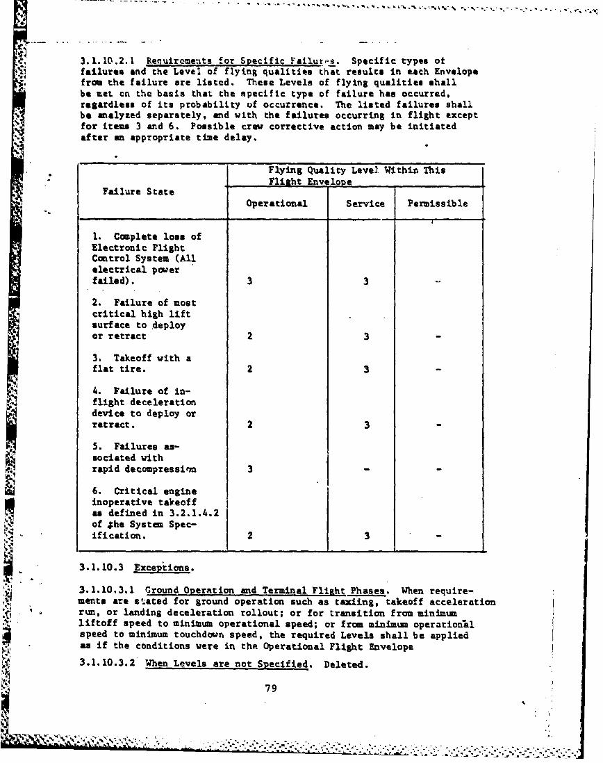
3.1.10.2.1 Reguiraments for Specific Failures. Specific types offailures and the Level of flying qualities that results in each Envelopefrom the failure are listed. These Levels of flying qualities shallbe rat cn the basis that the specific type of failure has occurred,regardless of its probability of occurrence. The listed failures shallbe analyzed separately, and with the failures occurring in flight exceptfor items 3 and 6. Possible crew corrective action may be initiatedafter an appropriate time delay.
Flying Quality Level Within This
Flieht Envelope_Failure State
Operational Service Permissible
1. Complete loss ofElectronic FlightControl System (Allelectrical powerfailed). 3
2. Failure of mostcritical high liftsurface to deployor retract 2 3
3. Takeoff with aflat tire. 2 3
4. Failure of in-flight decelerationdevice to deploy orretract. 2 3
5. Failures as-sociated withrapid decompressian 3 -
6. Critical engineinoperative takeoffas defined in 3.2.1.4.2of 4he System Spec-
.. ification. 2 3
3.1.10.3 Exceptions.
3.1.10.3.1 Ground Operation and Terminal Flight Phases. When require-ments are stated for ground operation such as taxiing, takeoff accelerationrun, or landing deceleration rollout; or for transition from minimumliftoff speed to minimum operational speed; or from minimum operationalspeed to minimum touchdown speed, the required Levels shall be appliedas if the conditions were in the Operational Flight Envelope
3.1.10.3.2 When Levels are not Specified. Deleted.
79
3.1.10.3.3 Flight Outside the Service Flight Envelope. It shall bereadily possible to safely return to the Service Flight Envelope fromall points in the Permissible Flight Envelopes without exceptional pilotskill or technique. Special Failure States and Specific Failure Stateswhich do not have a design requirement in the Permissible Envelopeare excluded. The requirements on flight at high-angle-of-attack,dive cdaracteristics, dive recovery devices, and dangerous flight con-ditions shall also apply.
3.1.11 Interpretation of Quantitative Requirments. Deleted.(Have moved this paragraph to Section 4, 4.2).
3.1.12 Assault Mode of Operation. Maximum use of power lift effectsfor airplane performance can be achieved by reducing the normal speedand control margins provided to account for failures. If th:.s reducedmargin region is utilized, a minimum of Level 2 handling qualitiesmust be provided prior to failure occurrence.
3.2 Longitudinal Flying Qualities. Two primary longitudinal control-lers are allowed. A third controller may be used if the pilot does nothave to remove his hand(s) from the primary controller(s) to operateit. Contractor must define what primary airplane response is expectedfrom each controller. If the response varies with airspeed, flap anele,etc., this must be defined.
3.2.1 Longitudinal Stability.
3.2.1.1 Longitudinal Static Stability. There shall be no tendencyfor the airspeed to diverge aperiodically when the airplane is disturbedfrom trim due to external disturbances with the cockpit controls fixedand with them free, except as allowed by 3.2.2.1.2. For airplanestates that include automatic reduction of pilot control forces forsteady state variations in speed or load factors, stable or neutralelevator control force and elevator control position with airspeed andload facto- may be provided. The automatic reduction of forces shallnot result in any reversal of the pilot's control force (i.e., frompush to pull or vice versa).
For all other airplane states this requirent will be consideredsati.efied if the variations of elevator control force and elevat.r con-trol position with airspeed are smooth and the local gradients stablewith: Trimmer and throttle controls not moved from the trim settingsby the crew and lg acceleration normal to the flight path, and constantaltitude over a range about the trim speed of ±15 percent or i50 knotsequivalent airspeed, whichever is less (except where limited by theboundaries of the Service Flight Envelope).
R .
: ' " , ~~.. .. .. .. ....... . . ... '...... .""..... .... :o
Stable gradients mean increasing pull forces end aft motion ofthe elevator control to mai.tain slower airspeeds and the opposite tomaintain faster airspeeds. Neutral gradients mean zero pull forcesand no motion of the elevator control to maintain slower or fasteralrspeeds. The term gradient does not include that portion of.the con-trol force or control positions versus airspeed curve within the pre-loaded breakout force or friction range.
3.2.1.1.1 Relaxation in Transonic Flight. The requirements of 3.2.1.1may be relaxed in the transonic speed range provided any divergent air-plane motions or reversals in slope of elevator control force and ele-vator control position with speed are gradual and not objectionable tothe pilot. In no case, however, shall the rourements of 3.2.1.1 berelaxed more than the following: a. Levels I and 2 - For center-stickcontrollers, no local force gradient shall be more unstable than 3pounds per 0.01 H nor shall the force change exceed 10 pounds in theunstable direction. The corresponding limits far wheel controllers are5 pounds per 0.01 H and 15 pounds, respectively. b. Level 3 - Forcenter-stick controllers, no local force gradlmt shall be more unstablethan 6 pounds per 0.01 H nor shall the force a exceed 20 pounds inthe unstable direction. The corresponding lintin for wheel controllersare 10 pounds per 0.01 H and 30 pounds, respetivAly. This relaxationdoes not apply to Level 1 for any Flight Phase uhich requires prolongedtransonic operation.
3.2.1.1.2 Elevator Control Force Variations During Rapid Speed Changes.When the airplane is accelerated and decelerated rapidly through theoperational speed range by the most critical combination of changes inpower, actuation of deceleration devices, stee- turns and pullups, themagnitude and rate of the associated trim chana shall not be so greatas to cause difficulty in maintaining the desired load factor by normalpilot techniques.
3.2.1.2 Phugoid Stability. The long-period airspeed oscillations whichoccur when the airplane seeks a stabilized -,'.speed following a disturb-ance shall meet the requirements of parap.-a b 3.2.2.1.2.
3.2.1.3 Hands on Fliaht-Path Stability. Flight-path stability isdefined in terms of flight-path-angle change where the airspeed ischanged by the use of the elevator control only (throttle and flapsetting not changed by either the crew or automatic devices). Specif-ically, this requirement is applicable whe, an airspeed hold mode asdefined in 3.2.5 is not functioning. Conversely this requirement isnot applicable when a speed hold mode is functioning. For the LandingFlight Phase and when the longitudinal column is used chiefly for rapidflight path control, the steady state flight-path-angle versus steadystate true-airspeed curve shall have a local slope at Vas n which isnegative or less positive thani
81
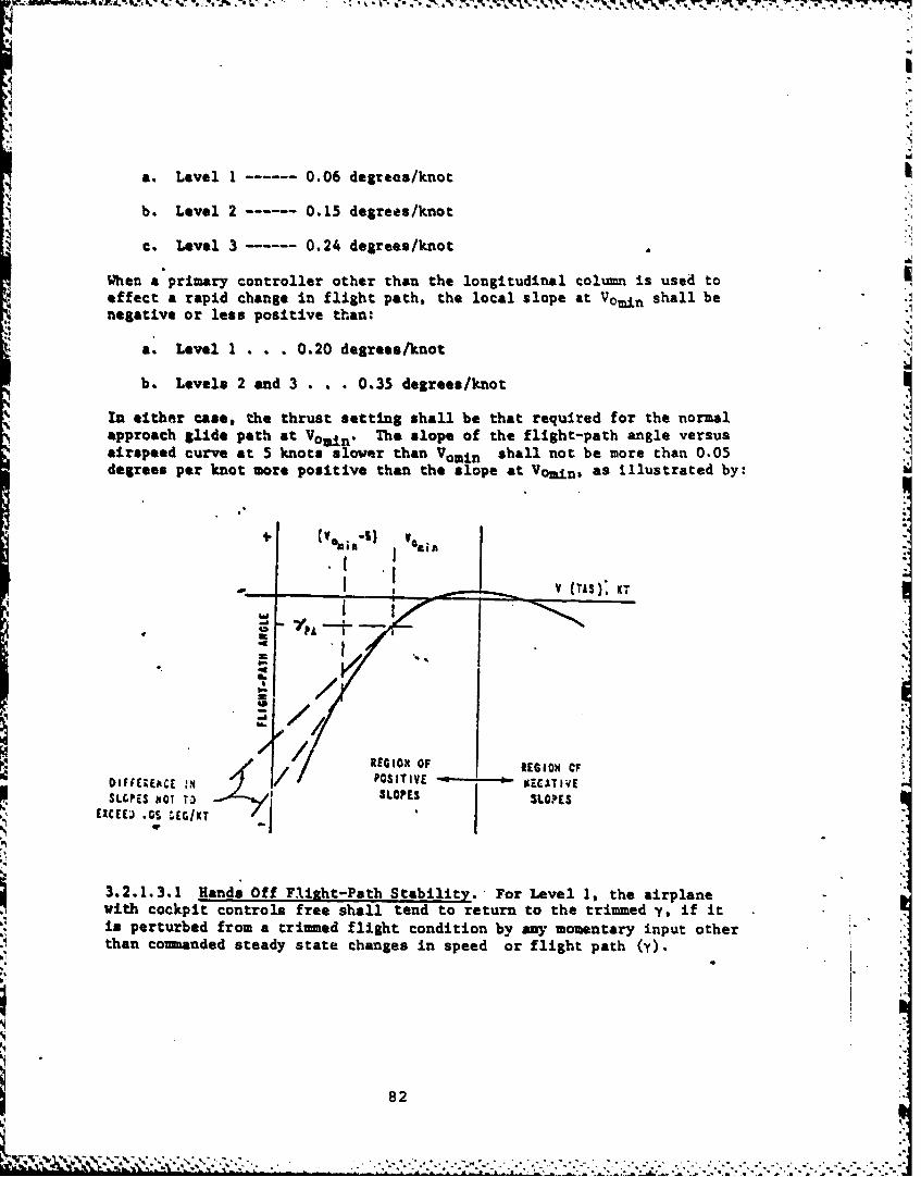
a. Level I - 0.06 degrees/knot
b. Level 2 - 0.15 degrees/knot
c. Level 3 0.24 degrees/knot
When a primary controller other than the longitudinal column is used toeffect a rapid change in flight path, the local slope at Vomin shall benegative or less positive than:
a. Level 1 . . . 0.20 degrees/knot
b. Levels 2 and 3 . . . 0.35 degrees/knot
In either case, the thrust setting shall be that required for the normalapproach glide path at Vo n" The slope of the flight-path angle versusairspeed curve at 5 knots slower than Vomin shall not be more than 0.05degrees per knot more positive than the slope at Vomin, as illustrated by:
EGai
aKT
REGIOO OFCF0; R Cvv. G r IOIO OF
DIFMEECE . POSITIVE S KECATIVESLC.P1S NOT TO SLOPES j SLOPES
EXCEEU .0!. :ECIKT
3.2.1.3.1 Hands Off Flight-Path Stability. For Level 1, the airplanewith cockpit controls free shall tend to return to the trimmed y, if itis perturbed from a trimmed flight condition by any momentary input otherthan commanded steady state changes in speed or flight path (y).
82
VI'- - -k. ., , .. --.-... .. ,. ... ..- ,. "
3.2.1.4 Pitch Attitude Versus Flight Path Antle. For the LandingFlight Phase, the ratio of the steady state attitude change to flightpath angle change (60/hy) at constant airspeed for column inputs, forairplanes that use the longitudinal column for rapid flight path control,shall be as follows:
Level min Max
1 0.75 1.5
2 0.5 1.5
3.2.1.5 Velocity Chanje Versus Fliht Path Angle. For the Landing FlightIPhase with maximum flap deflection, the slope of the steady state velocitychange to flight path angle change (Au/hy), at constant pitch attitude, and
0 with variation of thrust about the trim approach thrust setting, shall benear the value of zero for Level 1 and 2. This requirement applies to air-planes that do not use the longitudinal column for rapid flight path controland at the minimum operational speed.3.2.2 Longitudinal Maneuvering Characteristics.
3.2.2.1 LoXitudinal Response. Requirements for the responses of angleof attack, pitch rate, load factor, and airspeed tich are produced byabrupt pilot inputs of the appropriate primary controller(s), are addres-sed by 3.2.2.1.1 and 3.2.2.1.2. These requirements apply with the cock-pit controls fixed and with them freed, after the input is made, forresponses of any magnitude that might be experienced in normal serviceuse. If oscillations are nonlinear with amplitude, the requirementsshall apply to each cycle of the oscillation. For Normal States with apitch attitude hold mode as defined in 3.2.7, :!eas requirements do notapply when the airplane is within the static accuracy band of ±0.5 degreesdefined in 3.2.7.
3.2.2.1.1 Short-Term Frequency and Acceleration Sensitivity. The shortterm natural freqvency response of angle of attack, pitch rate and loadfactor at constant airspeed for the total airplane aerodynamics, flightcontrols, augmentation and propulsion system shall be similar to a secondorder response and shall be within the limits shown in Figures 1, 2, and3. The Level 3 lower bounds on wnSP and n/a of Figure 3 may be relaxedif compliance In shown with the requirements of 3.2.2.1.4. Note thatthe n/a to show compliance with this requirement is due only to themovement of the longitudinal column. "
8I83
I
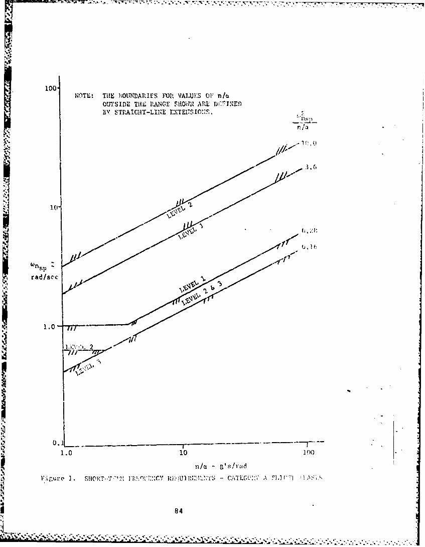
- -. '
100.NOM.: THlE 1hUNDARME FOJR VALUES OFi n/tL
OUTSIDE THiL RANGE SHOI AREL Di.7INED
r l
V'..-1f
:10.
rad/sc'c
1.0-
619K" ,'I,/
I0
0 :irurv I . EIO T*': *~''::Y R-'U 1 h.:. 11-l ,- - :/L': A TIACT'I
84
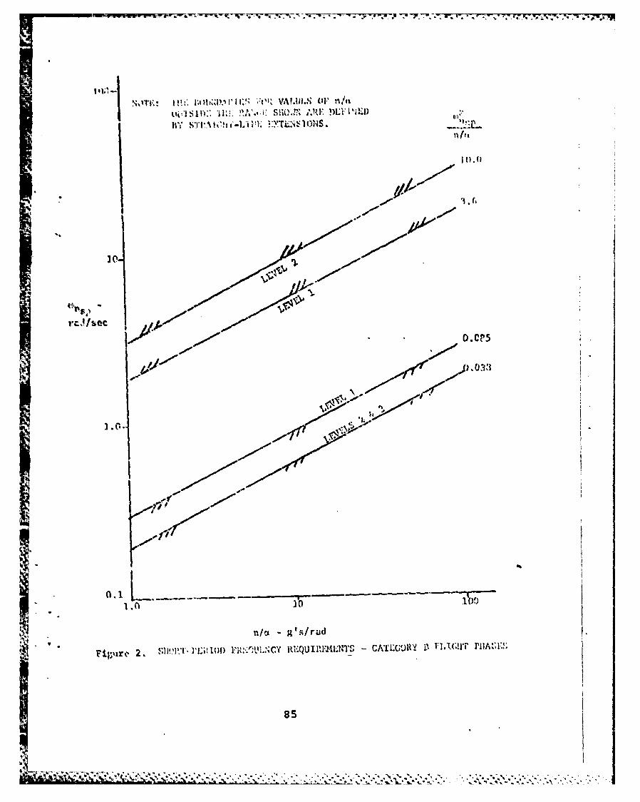
!!A % lICZ, 10" M
I I)
- ~I C
20Tr
n/o
.1cut r.UC-, "l-"
85~'
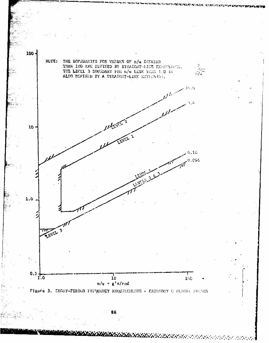
300-
NOTE: THlE 1wOPuDar (.IPS FO AiLuE-s or,/aCiF~11IAN 100 AR~E WL1eD Il ...ict~i]: I;> -~~ ('2TI LLVLL 3 4~L1;AR'Y 1.0i. nt 1'SS 'i I;~ 1 o 1:ALVO M.'IRLD BY A ~~A ;TLN ;i .
10-.
100I-
U0 1
n/u & 's/rndl
rigurce 3. ""HOX -IZIE1 l ) Ri~U ~ C IUQ 11iiJ;MBIl - (''J 1 \ I I, CH p* 86
- i210%
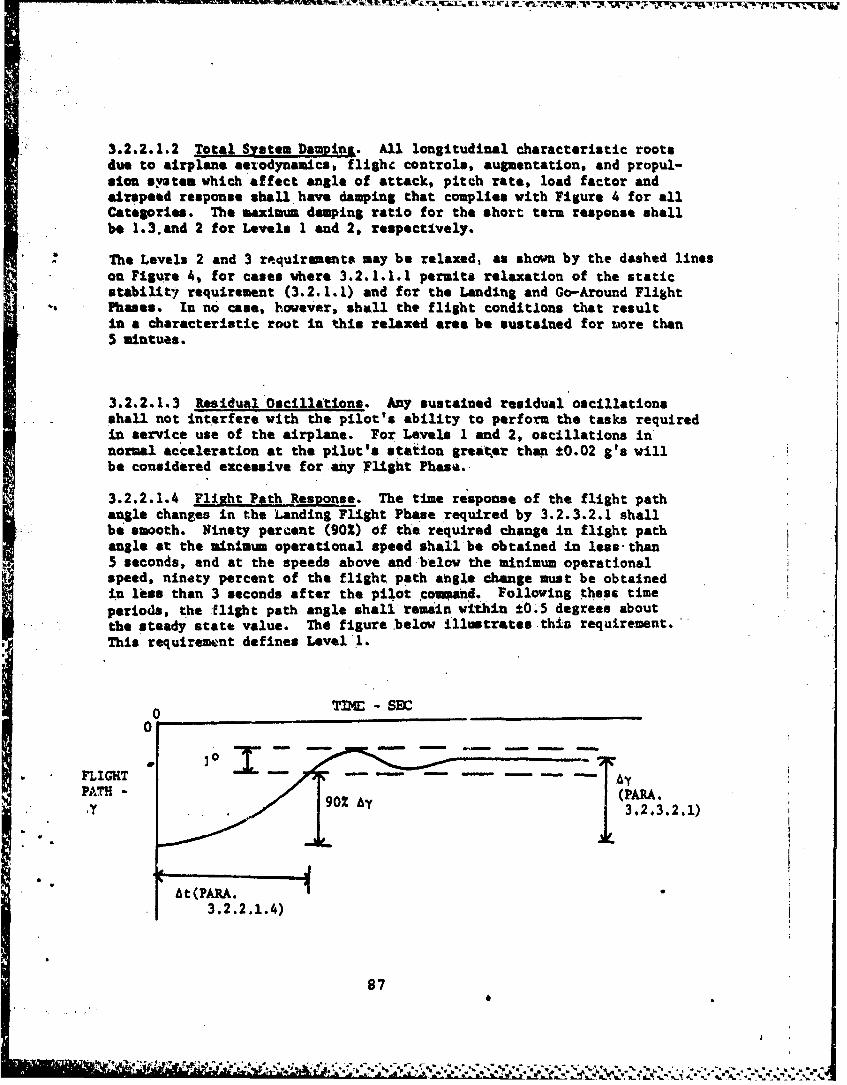
3.2.2.1.2 Total System Daugiol. All longitudinal characteristic rootsdue to airplane aerodynamics, flighc controls, augmentation, and propul-sion systen which affect angle of attack, pitch rate, load factor andairspeed response shall have damping that complies with Figure 4 for allCategories. The maximum damping ratio for the short term response shallbe 1.3.and 2 for Levels 1 and 2, respectively.
The Levels 2 and 3 requirements may be relaxed, as shown by the dashed lineson Figure 4, for cases where 3.2.1.1.1 permits relaxation of the staticstability requirement (3.2.1.1) and for the Landing and Go-Around FlightPhases. In no case, however, shall the flight conditions that resultin a characteristic root in this relaxed area be sustained for wore than5 mintues.
3.2.2.1.3 Residual Oscillations. Any sustained residual oscillationsshall not interfere with the pilot's ability to perform the tasks requiredin service use of the airplane. For Levels 1 and 2, oscillations innormal acceleration at the pilot's station greater than +0.02 g's willbe considered excessive for any Flight Phase.
3.2.2.1.4 Flight Path Response. The time response of the flight pathangle changes in the Landing Flight Phase required by 3.2.3.2.1 shallbe smooth. Ninety percent (902) of the required change in flight pathangle at the minimum operational speed shall be obtained in less-than5 seconds, and at the speeds above and below the minimum operationalspeed, ninety percent of the flight path angle change must be obtainedin les than 3 seconds after the pilot coaned. Following these timeperiods, the flight path angle shall remain within ±0.5 degrees aboutthe steady statt value. The figure below illustrates this requirement.This requirement defines Level 1.
0 M DE -$D
PATH - (PARA.SIy 3.2.3.2.1)
At (PARA.3.2.2.1.4)
87
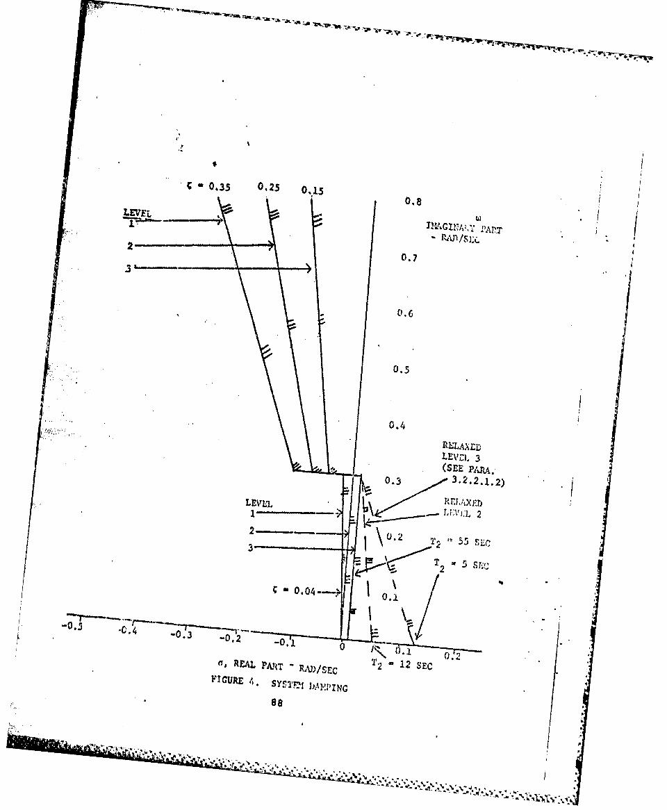
*0.35 0.25 0,1LEVEL08
0.7
0.6
LEVZI. 3(ME PAPA.
0.3 3.2.2.1.2)
LEVELET
1 L\> __LL2
0 .. 0-4 0
-0. 0.3 0.2 0
nREAL P~AM~ - R )/ C 2 12 SEC 0 2ImICURE 4.SY'S"'r- DAMPING
88

3.2.2.2 Ciontrol r~eal and Stability in Haneurering: Fliat. In steadyturning flight and in pull-ups at constant speed,, the elevator controlforce and elevator control deflection required to maintain a change intormal acceleration @hall be in the same sense as thorne required toInitiate the load factor change; that Is, airplane-nose-up control in-puts t9? maintaiv an increase In normal acceleration, airplane nose-downcontrol Inputs to maintain a decrease In normal acceleration. Themerequirements apply to local gradients In constmt-&iropeed maneuversthroughout the range of service load factors Weined In 3.1.8.4. Thisrequirement applies f or Levels 1 and 2.
3.2.2.2.1 Control Foxces &S Maneuveing Iligbt. At constant speed inpullups and pushovers, the variations In elevator-coutrol. force vithsteady sa normal acceleration shall be approximately linear. Adeparture from linearity resulting In a local gradient which differsfrom the average gradient for the maneuver by acre than 50 percent isconsidered excessive within the Operational and Service Envelopes. Alllocal forcs gradients shall be within the limts of Table IV. The termgradient does not include that portion of the force versus load factorcurvt within the preloaded breakout force or friction band. With11ormal States that Include automatic reduction of pilot control iorcesfor steady state changes in load factor, the gradients of Table IV donot apply.
3.2.2.2.2 Control-Motions In ManeuverIng Flight. The elevator-controlmotions in mnevering f light shall not be so large or so small as tobe objectionable. For Category A Flight Phases, the average gradientof elevator-control force per inch-of elevator-control deflection atconstant speed shall be not loe than 5 pounds per inch for Levels 1and 2.
3.2.2.3 1n itudinal Pilot-Induced Oscillation. There shall 'w notendency for pilot-induced oscillations that are sustained or uncontrol-
* lable resulting from the efforts of the pilot to control the airplane.This requirement and 3.2.2.3.1 apply for Levels 1. 2, and 3.
3.2.2.3.1 Transient Control Forces. The pcok elevat or-control forcesdeveloped during abrupt maneuvers at constant speed shall not be objec-tionably light, and the buildup of control force during the maneuver entryshall lead the buildup of aotmal acealratic;. Specifically, the followingrequirement shall be met when the elevator control is pumped sinumoidally,.Fot all input frequencies up to structural mode frequencies the ratio ofthe Ipeak~ force amplitude to the pa normal load-factor' san 1 itude at thecenter of gravity, measured from the steady oscillation, shall be greaterthan 3. 0 pounds per g.
89
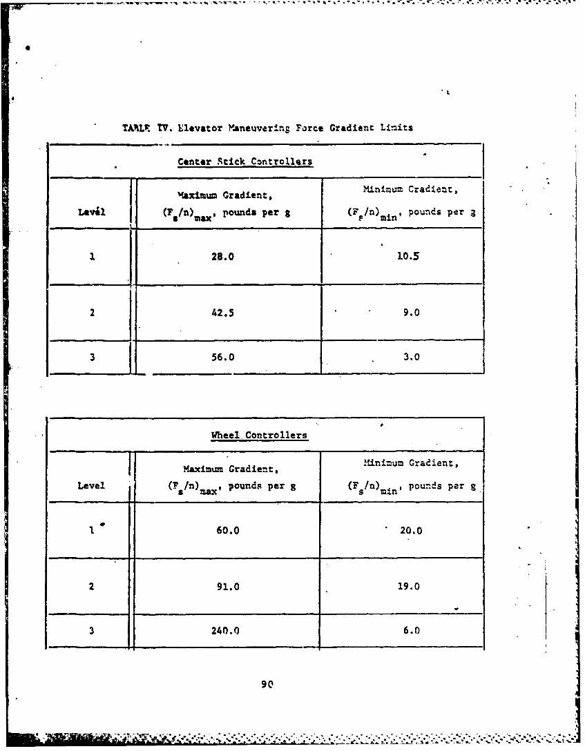
TAILr TV. Elevator Maneuvering Force Gradient Limits
Center Stick Controllers
I RMaximum Gradient, Minimum Cradient,
Lev (F/)Max, pounds per & (F /n) mi, pounds per a "1
28.0 10.5
2 42.5 9.0
56.0 3.0
Wheel Controllers
Maximum Gradient, Minimum Gradient,
Level (F /n)max, pounds per g (Fs /n)mn' pounds per g
1 60.0 20.0
2 91.0 19.0
3 240.0 6.0
90
ma "5-- * * .6:
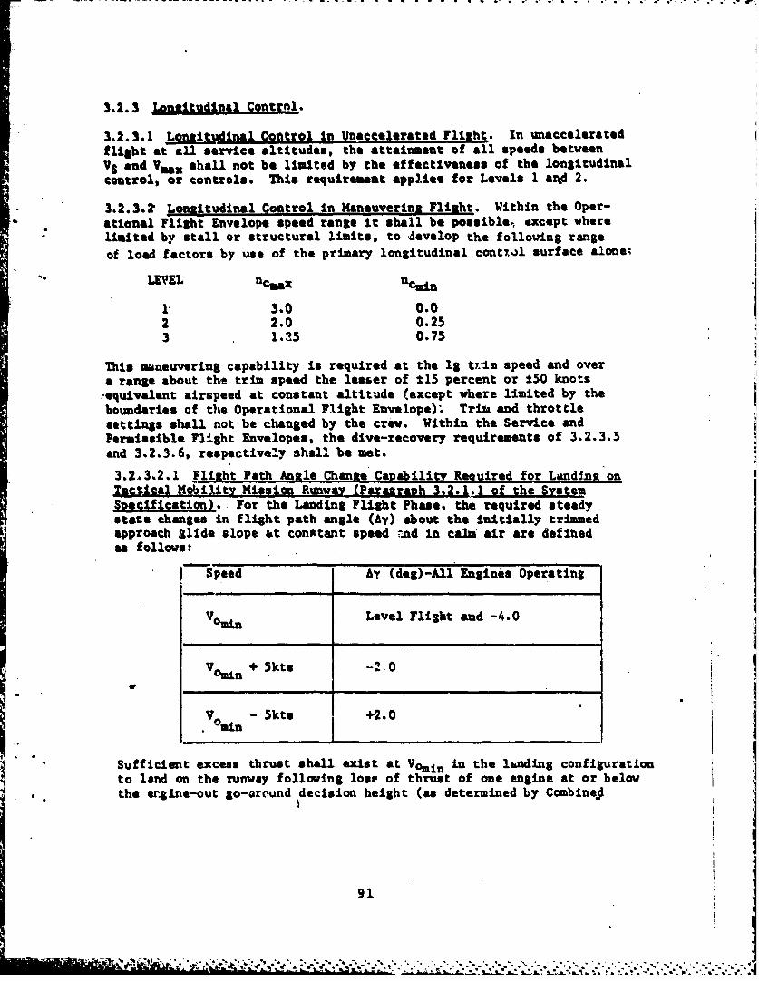
3.2.3 Lontitudinal Contrnl.
3.2.3.1 Longitudinal Control in Unaccelerated Flight. In unacceleratedflight at tll service altitudes, the attainment of all speeds between
VS and Vmax shall not be limited by the effectiveness of the longitudinalcontrol, or controls. This requirement applies for Levels I arid 2.
3.2.3.? Longitudinal Control in Maneuvering Flight. Within the Oper-ational Flight Envelope speed range it shall be possible, except wherelimited by stall or structural limits, to develop the following range
of load factors by use of the primary longitudinal contzil surface alone%
LEVEL ncmex nCain
1 3.0 0.02 2.0 0.253 1.25 0.75
This maueuvering capability is required at the lg v.-i speed and overa range about the trim speed the lesser of ±15 percent or ±50 knots-equivalent airspeed at constant altitude (except vhere limited by theboundaries of the Operational Flight Envelope). Trita and throttlesettings shall not be changed by the crew. Within the Service andPermissible Flight Envelopes, the dive-recovery requirements of 3.2.3.5and 3.2.3.6, respectively shall be met.
3.2.3.2.1 Flight Path Angle Chante Cagability Required for Landing onTactical MobiMlty Missin Runway (Paragraph 3.2.1.1 of the SystemSnecification). For the Landing Flight Phase, the required steadystate changes in flight path angle (Ay) about the initially trimmedapproach Slide slope at constant speed -nd in cals air are definedas follows:
) Speed Ay (deg)-All Engines Operating
Vomin Level Flight and -4.0
V + Skts -210
CminV om - 5kis +2.0
Sufficient excess thrust shall exist at Vomin in the landing configurationto land on the runway following lose of thrust of one engine at or below
. the er4ine-out go-around decision height (as determined by Combinej
91
- _, , . . ,- LA .-- . ...........-..--.
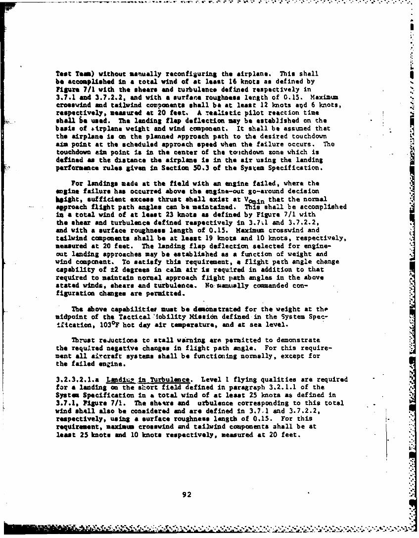
Test Tem) without manually reconfiguring the airplane. This shallbe accomplished in a total wind of at least 16 knots as defined byFigure 7/1 with the shears and turbulence defined respectively in3.7.1 and 3.7.2.2, and with a surface roughness length of 0.15. Maximumcrosswind and tailvind con-ponents shall be at least 12 knots a?)d 6 knots,respectively, measured at 20 feet. A tealistic pilot reaction timeshall be used. The landing flap deflection may be established on thebasis of &trplane weight and wind component. It shall be assumed thatthe airplane is on the planned Approach path to the desired touchdownaim point at the scheduled approach speed when the failure occurs. Thetouchdown aim point is in the center of the totichdown zone which isdefined as the distance the airplane Is in the air using the landingperformance rules given in Section 50.3 of the System Specification.
For landings made at the field with an engine failed, where theenglne failure has occurred above the engine-out go-around decisionkight, sufficient excess thrust shall exist at Vomin that the normalqproach flight path angles can be maintained. This sha~.l be accomplishedin a total wind of at least 23 knots as defined by Figure 7/1 withthe shear and turbulence defined respectively in 3.7.1 and 3.7.2.2,and with a surface roughness length of 0.15. Maxinum crosswind andtailwind components shall be at least 19 knots and 10 knots, respectively,measured at 20 feet. The landing flap deflection selected for engine-out landing approaches may be established as a function of weight andwind component. To satisfy this requirement, a flight path angle changecapability of ±2 degrees in calm air Is requ:Lred in addition to thatrequired to maintain normal approach flight path angles in the abovestated winds, shears and turbulence. No santally commanded con-figuration changes are permitted.
The above capabilitier must be demonstrated for the weight at themidpoint of the Tactical.'tobility Mission defined in the System Spec-iltcation, 1030F hot day air temperature, and at sea level.
Thrust reductions to stall warning are permitted to demonstratethe requJired negative changes in flight path angle. For this require-ment all aircraft systems shall be functioning normally, except forthe failed engine.
3.2.3.2.1.a LadlU in Turbulence. Level 1 flying qualities are requiredfor a landing on the short field defined in paragraph 3.2.1.1 of theSystem Specification in a total wind of at least 25 knots as defined in3.7.1, Figure 7/1. The sheers and urbulence corresponding to this totalwind shall also be considered and are defined in 3.7.1 and 3.7.2.2,respectively, using a surface roughness length of 0.15. For thisrequirement, maximum crosswind and tailvind components ahall be atleast 25 knots and 10 knots respectively, measured at 20 feet.
92
All airplane systems are assumed to be operating normally. Theweight at the midpoint of the Tactical Mobility Mission defined in theSystem Specification, 1030 F hot day air temperature, and at see levelshall be used for the analysis.
3.2.3.2.2 Turn Rate. During the Landing Flight Phase, at themaximumpossible pilot selected flap deflection (contractor may specify specific
Snumber), & constant turn rate of 7.5 degrees per second is requiredfor Level 1 at the minimum operational speed and on the trimmed approachglide slope. This condition shall be demonstrated for the weight atthe midpoint of the Tactical Mobility Kission defined in the System Specification10307 hot day air temperature, all engines operating and at sea level.
3.2.3.2.3 Direct Normal-Force Control. Use of devices for direct normalforce control shall not produce objectionable changes in attitud- forany amount of control up to the maxim=m available. This requirementshall be met for Levels 1 and 2 and shall be safe for Level 3.
3.2.3.3 Lonzitudinal Control in Takeoff. The effectiveness of theelevator control shall not restrict the takeoff performance requiredof the airplane and defined in the System Specification, and shall besufficient to prevent over-rotation to undesirable attitudes duringtakeoffs. Satisfactory takeoffs shal not be dependent upon use ofthe trimmer control during takeoff or on complicated control manipula-tion by the pilot. These requirements shall be met on hard-surfacedrunways and unprepared fields that are specified in the System Spec-ification. This requirement defines Levels 1, 2. and 3.
3.2.3.3.1 Longitudinal Control Force and Travel in Takeoff. With thetrim settina optional but fixed, the elevator =trol forces requiredduring a4ll types of takeoffs defined in the-bSstem Specification shallbe within the following limits.
Level i: 30 pounds pull to 10 pounds push
Level 2: 50 pounds pull to 20 pounds p wh
The elevator control travel during these takeoffs shall not exceed 75percent of the total travel, stop-to-stop. Here the term takeoff includesthe ground run, rotation, lift-off and the ensuing acceleration to climbspeed. Takeoff power shall be maintained tmtil climb speed' is reached,vith the landing gear and highlift devices retracted in the normal mannerat speeds from Vernn (TO) to Vomax (CL).
3.2.3.4 Longitudinal Control in Laid ins. The elevator control shallbe sufficiently effective in the Landing Flight Phase in ground effectthat the geometry limited touchdown attitude or the stall angle of
93

attack can be maintained with any thrust setting. This requirementshall be net with he airplane trimmed for the minimum operationalspeed in free air. 7he requirements above define Levels I and 2.?or Level 3, it shall be possible to execute safe approaches and landingsit, the presence of a 15 kt total mean wind, roughness length of 0.15and asqociatod turbulence levels as defined In paragraph 3.7.2.2.
3.2.3.4.1 LonAitudinol Control arces in Landing. The elevator controlforces required to meet the requirements of 3.2.3.4 shall be pull forcesand shall not exceed the following:
Le~~ )Maximum Control Force - Pounds
1 302 5o3 75
3.2.3.4.2 Landing Control Power. A load factor (n) of 1.2g's shall beavailable for flare at the minimum operational speed before the stallwarning is encountered. The requirement applies for .the Landing FlightPhase, with trim set for approach, without grumnd effects, and vith anInitial thrust setting required for the approach configuration and air-speed. This requirement apiles for Levels 1, 2, iand 3.
3.2.3.4.3 Pitch Acceleration. With the aircraft initially trivmed atthe minimum operationatl speed for the Landisg Flight Phase, it shallbe possible to achieve a 3-degree attitude thbmge within one second dueto longitudinal column step input only. This requirement defines theminimum-Level I capability and shall be demontrated in the most criticalsteady sideslip required for engine out or crosiuind (3.3.7) and outof ground effects.
3.2.3.5 Lonuitudinal Control Forces in Dives - Service Flight Envelope.With the airplane trimmed for level flight at speeds throughout theService Flight Envelope, the elevator control forces in 7.5 degree dives
bhld for at least 20 seconds duration within the Service Flight Envelopeshall not exceed 30 pounds push or 15 pound8 pull. In similar dives,but with trim optional following the dive entry, it shall be possiblewith normal piloting techniques to maintain the forces within the limitsof 16 pounds push or pull. The forces required for recovery from thesedives shall be in accordance with the gradients specified in 3.2.2.2.1although speed may vary during the pullout. In no case shall the forcesbe greater thah 100 pounds during the pullout.
3.2.3.6 Lonsitudinal ConL -1 Forces in Dives - Permissible Flight Envelopes.With the airplane trimmed for level flight at the maximum service speedbut with trim optional in the dive, it shall be possible to mainthin the
94
944

elevator contol force within the limits of 35 pounds push or pull indives to all attainable speeds within the Permissible Flight Envelope.The force required for recovery from these divas shall not exceed 125potmds. Trim and deceleration devices, etc., moy be used to assist inrecovery If no unusual pilot technique Is required. This requirementdefinep Level 3.
3.2.3.7 *Lonaltudinal Cotrol in Sideslins. With the airplane trimmedfor 1 "a" load factor, wings level, zero sideslip flight* the elevatorcoutrol force *hall be between 10 pounds push or pull to maintain
* constant speed In steady sideslips with up to 50 pounds of rudder pedalforce In either direction. If a variation of elevator ronitrol forcewith sideslip does exist* Increasing pull for&* shall accompany Increasinguideslip. and the magnitude and direction of the force chwa besimilar for right and left sideslips. These requirements define LevelsI and 2. For Level,3, therea ball be no wicotrollable pitchingnotions associated with the sidslips discusseod above.
3.21. itc Ati.do Cinnd. for a pitch attitude comand mode, thePitch attitude of the aircraft shall be proportional to a longitudinalcolum displacement from the pitch control trim position. A push forceand forward cockpit-control displacement *hall be required to decreasepitch attitude. and a pull force and aft cockpit control displacementshall be required to increase the pitch attitd. When the columnIs displaced In either direction and then released the aircraft shallreturn to the Initially referenced attitude vams the referencedattitude has been changed by a pilot or automtic cememad. The cosmndedpitch attitude change versus time shall be &moth, jad the requiredperformance defined (i.e., overshoot,, time hietway envelopes, etc..)by the contractor. The limits on the-change is4 pitch attitude to thepilot stick force shall be defined by the ton~ctor based on prototypeflight test results.
3.2.5 r ed Command and Rold M4odes. The n~mded airspeed changeversus ti~ke shall oepmooth arnd th, desired performance defined (i.e.,overshoo s, t ime hist oryeanvelop ee)by the contractor. 'For an /airspee4' hold mod,"the airspeed elected by the pilot shell'be theref. ae. Indicated airuspeed all be maintained within, t5 knots or±2 Per ent of the/ .referenced a speed, whichever In greater, 1e1;5 Ptingr/gust pikes wi= durto usta ea ,In the' followtag
at erca ironneatnt- asta /e"
of 0.15 and a correspoding tuibjlence as def ed* ~~~in 3.7 2.2. /ascz:
High urbule. ce e itofZeeedeice of02adefined in Figure 716.
95
Any periodic osc,llation within this limit shall have a period of atleast 20 seconds.
3.2.6 Ptcb Rate Cnand Mode. For i. pitch rate coumand mode, the pitchrate of the aircraft shall be proportional to a longitudinal column dis-placement from the pitch control trim position. A push force and forwardcockpit control displacement shall be required for an airplane nose-downpitch rate, and a pull force and aft cockpit control displacement shallbe required for an airplane nose-up pitch rate. The comeanded pitch ratetime history shall be smooth, and the required performance defined (i.e.,overshoot, time history envelopes, etc.) by the contractor. The limitson the chae in pitch rate to the pilot stick force shall be definedby the contractor based on prototype flight test results.
37.2. Pith Hold Mode. In those airplane states that include attitude-o-ld modes, the airplane shall maintain referenced pitch attitudes through-out the Operational 'light Envelope In the presence of longitudinaltrim changes associated with thrust changes, secondary control systemoperation, normal configuration changes, durIag lateral-directionalmaneuvers normally required for mission accouqlshment, and in the followingatmospheric environments
Low Altitude - 2Skt total wind using 3.7.1 with a roughness lengthof 0.15 and a corresponding turbulence as defined inparagraph 3.7.2.2.
High Altitude - Use turbulence levels associated with a probabilityof exceedence of 10-2 as defined in Figure 7/6.
Specifically, attitudes shall be ualntaiued in smoth air with staticaccuracy of 10.5 degree in pitch attitude (with wings level) with respectto the reference. UMS attitude deviations shall not exceed 2 degreesin pitch turbulence at the intensities specified. Accuracy requirementsshall be achieved and maintained within 3 seconds for either a 5 degreeattitude or a 0.5 *'"g" load factor disturba::e, Tbichever is !ess, causedby a gust Input.
3.3 Lateral-Directional Flying Oualittea.
3.3.1 Lateral-Directional Mode Characteristics. The overall lateral-directional damping ano frequency requirements for all the system modes
(except roll subsidence and structural modes) are shown on Figure 5.The lateral-directional characteristics shall not prevent the pilot fromperforming accurate touchdowns relative to a 60 foot wide runway.
3.3.1.1 Lateral-Directional Oscillations (Dutch Roll). The frequency,mad, and damping ratio, Cd, of the lateral directional oscillations
96
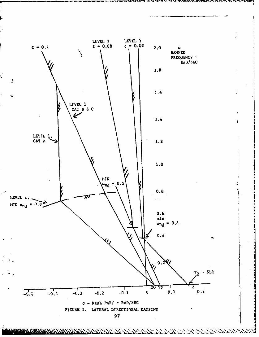
LIVEI, ,-'V I. L
0,k C 0,08 ; -0.02 2.0DAIMtI)FREQUENCY
1.8
CAT A %~1
1.0
MIN
0.8
0.6
I 0.4
0.2
T2 SEC
-0 0.1 0-2
a-REAL PART * RADIsrEC
-.
FIGURE S. LATERA\L DTRECT10NA.L DAMING
97
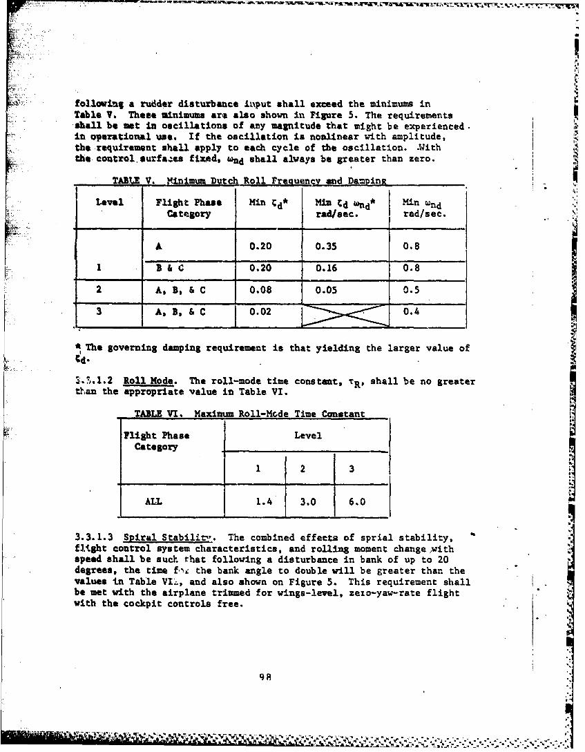
following a rudder disturbance iinput shall exceed the minimum inTable V. These minimums are also shown in Figure 5. The requirementsshall be met in oscillations of any magnitude that imight be experienced.-it operational use. If the oscillation is nonlinear with amplitude,the requirement shall apply to each cycle of the oscillation. *Withthe coutrol~surfae fixed, "wnd shall always be greater than zero.
TAL V. Minimum Dutch Roll Freauency and Damp mR
Level Flight Phase M d dd* Mi ndCategory rail/sec. Irad/sec.
A 0.20 0.35 0.8
B 3 &C 0.20 0.16 0.8
2 A, B, C 0.08 0.05 0.5
3 As ,,& C 0.02 0.4
*The governing damping requirement is that yielding the larger value of
__ _ _ _ __ _ _ _ __ _ _ _ __ _ _ _'
"..).1.2 Roll Mode. The roll-mode time constant, TRI shall be no greaterth~an the appropriate value in Table VI.
TABLE VI. Maximum Roll-Mode Time Constant
Flight Phase LevelCategory _______________
1 2 3
ALL 1.4 3.0 6.0
3.3.1.3 Spiral Stabilir",. The combined effects of sprial stability,flight control system characteristics, and rolling moment change withspeed shall be suct. that following a disturbance in bank of up to 20degrees, the time U~i the bank angle to double will be greater than thevalues in Table VI'i, and also shown on Figure 5. This requirement shallbe met with the airplane trimmed for wings-level, zezo-yaw-rate flightwith the cockpit controls free.
N!7X
ay8

TABLE VII. Spiral Stability - Minimum Time toDouble Amplitude
Flight Phase Level I Level 2 Level 3Category
* ALL 20 sec 12 sec 4 sec
3.3.1.4 Coupled=Roll-Spiral Oscillation. A coupled roll-spiral modeshall comply with Figure 5.
3.3.2 Lateral-Directional Dynamic Response Characteristics. Lateral-directional dynamic response characteristics are stated in terms ofallowable roll rate and bank oscillations, sideslip excursions, rolls*4ck or wheel forces, and rudder pedal forces that occur during specifiedtlling and turning maneuvers. The requirements of 3.3.2.2, 3.3.2.3,ond 3.3.2.4 apply for all roll control commands up to the magnituderequired to meet the roll performance of 3.3.4.
3.3.2.1 Lateral-Directional Response to Atmospheric Disturbances. Althoughno numerical requirements are specified, the airplane shall have acceptableresponse and controllability characteristics in atmospheric disturbances.The roll acceleration, rate, and displacement responses to side gusts shallbe investigated for airplanes with large roiling moment due to sideslip.
3.3.2.2 Roll Rate Oscillations. Following a rudder pedals free, largestep roll control command, the roll rate at the first minimum followingthe first peak shall be of the same sigu and not less than the following-percentage of the roll rate at the first peak:
Level Flight Phase Catea2ry Percent
1 A&B 70C 60
2 A&B 60C .25
3 ALL 10
For all Levels, ihe change in bank angle shall always be in the directionof the roll control tommand. The roll command shall be held fixed untilthe bank angle has changed at least 90 degrees (i.e., -450 to 450).
S.4 3.3.2.2.1 Not required.
99
.... . .---
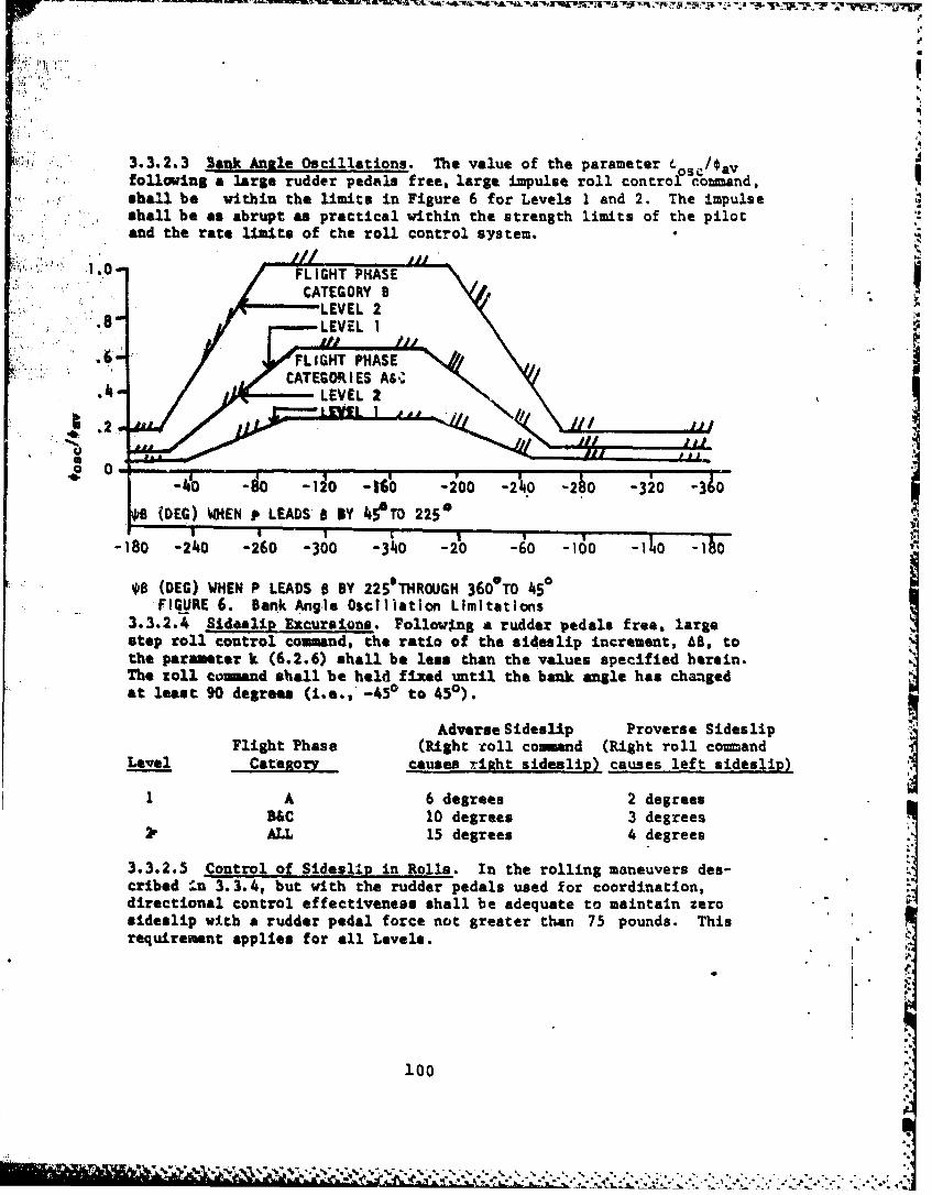
3.3.2.3 Bauk Anile Oscillations. The value of the parameter -/Ovfollowing a large rudder pedals free, largo impulse roll control coand,shall be within the limits in Figure 6 for Levels 1 and 2. The impulseshall be as abrupt as practical within the strength limits of the pilotand the rate limits of the roll control system.
:". : .",8" LEVEIL 2
' ": :" " ,FLIGHT PHASE ..
:¢ ' i "'. " CATEGORIES£ IAs
1.2.
-40 -80 -12 -I -200 -2%0 -260 -320 -310
BP (DEG) WHEN f LEADS 8 BY 45TO 225*
-180 -240 -260 -300 -340 -20 -60 -100 -16 -io
.. B (DEG) WHEN P LEADS B BY 225eTHROUGH 360*TO 450FIGURE 6. Bank Angle Osclliation Limitations
3.3.2.4 Sideslip Excursions. Followng a rudder pedals free, largestep roll control command, the ratio of the sideulip increment, A6, tothe parameter k (6.2.6) shall be less than the values specified herein.The roll conand shall be held fixed until the bank angle has changedat least 90 degrees (i.e., -450 to 450).
Adverse Sideslip Proverse SideslipFlight Phase (Right toll commnd (Right roll command
Level Cateaory causes right sideslip) causes left sideslip)
1 A 6 degrees 2 degrees
B&C 10 degrees 3 degreesALL 15 degrees 4 degrees
3.3.2.5 Control of Sideslip in Rolls. In the rolling maneuvers des-cribed I.n 3.3.4, but with the rudder pedals used for coordination,directional control effectiveness shall be adequate to maintain zerosideslip with a rudder pedal force not greater than 75 pounds. Thisrequirement applies for all Levels.
100
% V
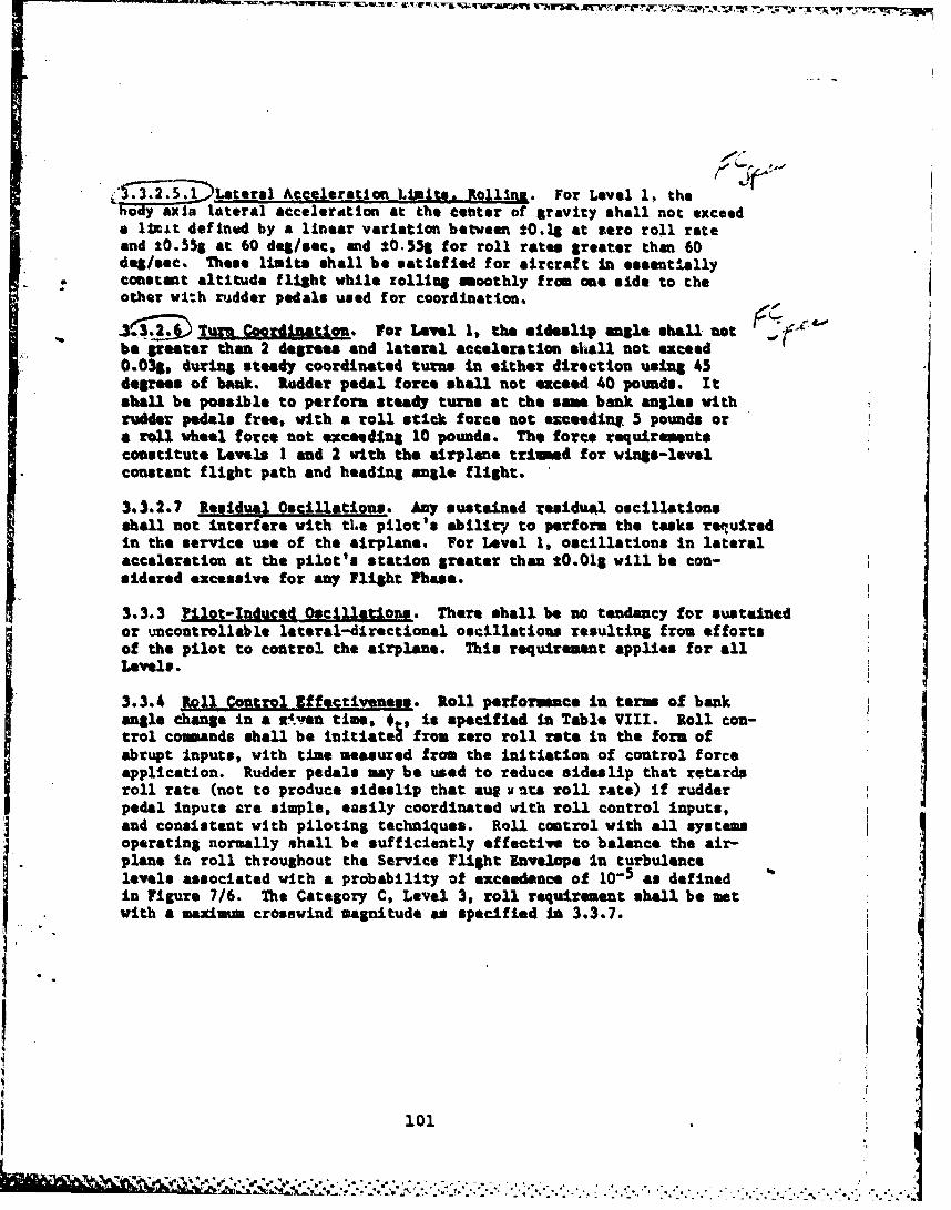
.4nij ,lateral Acceleration Lm ts. Rolling. For Level 1, thebody axis lateral acceleration at the center of gravity shall not exceeda limt defined by a linear variation between a0.lS at zero roll rateand 10.55& at 60 deg/sec, and 10.5%g for roll rates greater than 60deg/sec. These limits shall be satisfied for aircraft In essentiallyconstant altitude flight while zolling smoothly from one side to theother vi:h rudder pedals used for coordination.
3 .'j~ Turn Coordination. or Level 1, the sideslip angle shall -otbe greater than 2 degrees and lateral acceleration shall not exceed0.03g, during steady coordinated turns in either direction using 45degrees of bank. Rdder pedal force shall not exceed 40 pounds. Itshall be possible to perform steady turns at the same bank angles withrudder pedals free, with a roll stick force not exceediun 5 pounds ora roll wheel force not exceeding 10 pounds. The force requirementsconstitute Levels I and 2 with the airplane triined for wings-levelconstant flight path and heading angle flight.
3.3.2.7 Resduaul Oscillations. Any sustained residu4l oscillationsshall not interfere with tLe pilot's ability to perform the tasks requiredin the service use of the airplane. For Level 1, oscillations in lateralacceleration at the pilot's station greater than 10.01g will be con-sidered excessive for any Flight Phase.
3.3.3 Pilot-Induced Oscillations. There shall be so tendaucy for sustainedor uncontrollable lateral-directional oscillations resulting from effortsof the pilot to control the airplane. This requirement applies for allLevels.
3.3.4 Roll Control .ffectveness. Roll performace In term of bankangle change in a .ven time, n, s specified in Table VIII. Roll con-trol commands shall be initiated from zero roll rate in the form ofabrupt inputs, with time measured from the initiation of control forceapplication. Rudder pedals may be used to reduce sideslip that retardsroll rate (not to produce sideslip that au l unts roll rate) if rudderpedal inputs are simple, easily coordinated with roll control inputs,and consistent with piloting techniques. Roll control with all systemsoperating normally shall be sufficiently effective to balance the air-plane in roll throughout the Service Flight Envelope In turbulencelevels associated with a probability of exceedence of 10- 5 as definedin Figure 7/6. The Category C, Level 3, roll requirement shall be metwith a maximum crosswind magnitude as specified In 3.3.7.
I
i01
-1 .
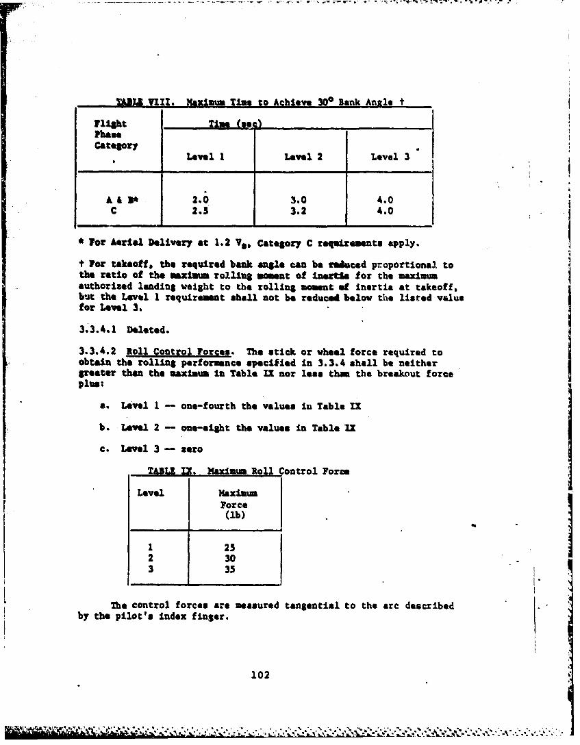
111lU. axlmum Time to Achieve 30° Bank Angle t
Flight Time (se I.PhameCategory
Level 1 Level 2 Level 3
A &3 2.0 3.0 4.0C 2.5 3.2 4.0
* For Aerial Delivery at 1.2 V&. Category C requirements apply.
t For takeoff, the required bank angle can be reduced proportional tothe ratio of the maxim= rolling moment of Inertia for the maximumauthorized landing weight to the rolling moment of inertia at takeoff,but the Level 1 requirement shall not be reduced below the listed valuefor Level 3.
3.3.4.1 Deleted.
3.3.4.2 Roll Control Forces. The stick or wheel force required toobt"n the rolling performance specified In 3.3.4 shall be neithergreater than the maximum In Table IX nor less than the breakout forceplus: lt
a. Level I - one-fourth the values in Table IX
b. Levelq 2 - one-eisht the values in Table IX
c. Level 3 - zero
TABLI I,. Maximum Roll Control Force
Level MaximumForce(ib)
1 252 303 35
The control forces are measured tangential to the arc describedby the pilot's index finger.
102
i~r '
. ' , 0 ' ". t ,-. . * "' . * . . * .. * . , '... "- " " . % % % , " " . % -. . . . . ..
3.3.4.3 Linaarltv of Roll Renonse. There shall be no objectionablenonliearities in the variation of roll rate for a rate comand systemmad of roll attitude for an attitude comand system with roll controldeflection or force. This Is considered a Level I and 2 requirement.
3.3.4.4 Wheel Control Throw. For airplanes with wheal controilers,the whiel throw necessary to meet the roll performance requirementsS specified in 3.3.4 shall not exceed 70 degrees in either direction.With all lateral augmentation off, the requirement ray be relaxed to00 degrees. This requirement applies to all Levels.
3.3.4.5 Deleted.
3.3.3 Directional Control Characteristics. Directional control charac-teristics shall enable the pilot to balance yawing moments and controlyaw and sideslip. Specifically, compliance with 3.3.5.1 through 3.3.5.5shall be demonstrated.
3.3.5.1 Directional Control with Saeed Chane. When '.nitially trimmeddirectionally with symtric power, the trim chqage with speed shallbe such that constant flight path and heading angle can be maintainedover a speed range of t30 percent of the trim speed or t1OO knots equiv-alent airspeed, whichever is less (except where limited by boundariesof the Service Flight Envelope). Rudder pedal forces shall not begreater than 40 pounds for Levels I and 2 nor 120 pounds for Level 3without retriming.
3.3.5.1.1 Directional Control with As -tric Lseding. Not applicable.
3.3.5.2 Directional Control In go-Around. The response to thrust,configuration, and airspeed changes shall be such that the pilot canmaintain constant heading angle during go arouvds initiated at speedsdoa to VS (PA), with rudder pedal forces not amceeding 40 pouads whentriied at Vomin (PA). The preceding requirmmts apply for Levels1 and 2. The Level 3 requirement is to maintain a constant beadingangle for these conditions with rudder pedi L forces not exceeding 120pounds. For all Levels, bank angles up to 5 degrees are permitted.Further, consistent satisfactory go around perfotmance shall beattained with a reasonable pilot workload.
3.3.5.3 Yaw Control. Within the Operational l1&t Envelope for theLanding Flight Phase, the yaw attitude change In 2 seconds for an abruptstep displacement of the yaw control shall be between 5 and 10 degreesfor Level 1. This requirement applies with the aircraft trimmed forsymmetrical flight and with the wings held level during the maneuver.
103
4L
3.3.5.4 Yaw Control Linearity And Sensitivity. There shall be no objec-tionable nonlinearities in the variation of directional response withyu control deflection or forces. There shall be no excessive sensitivityor sluggishness of airplane yaw response due to rudder pedal deflectionor force that would prevent such things as satisfactory turn c9ordination,decrab for touchdown in crosswind, or control of engine failure transients.
3.3.5.5 Reading Control. Within the Operational Flight Envelope forCategory C the heading delay, T$, shall be less than the values shownbelow:
Level T$, sac
1 1.22 2.03 3.0
The aircraft shall be initially trimmed when the maneuver is begun. Aneplanation of T$ is presented in 6.2.6.
3.3.6 Lateral-Directional Characteristics In Steady Sideslips. Therequirements' of 3.3.6.1 through 3.3.6.3.1 concern rudder pedal iv lucedA,unaccolerated, zero yaw rate sideslips with the-airplane trimned forwings level, constant flight path and heading angle. Paragraphs 3.3.6.1through 3.3.6.3 apply at sideslip angles up to those produced by full'rudder pedal deflections.
3.3.6.1 YMIM Mosnts in Steady Sideslips. For the sideslips specifiedin 3.3.6, right rudder pedal deflection and force shall produce leftsideslips and left rudder pedal deflection and force shall produceright sideslips. For Levels 1 and 2 the following requirements shallapply. The variation of sideslip angle with rudder pedal deflectionshall be linear for sideslip angles between +15 degrees and -15 degrees.For larger sideslip angles, an increase in rudder pedal deflection shallalways be required for an increase in sideslip. The variation of side-slip angle with rudder pedal force shall be linear for sideslip anglesbetween +10 degrees and -10 degrees. Although a lightning of rudderpedal force ds acceptable for sideslip angles outside this range, therudder pedal force shall never reduce to zero.
3.3.6.2 Side Forces in Steady Sideslips. For the sideslips of 3.3.6,an increase in right bank angle shall accompany an increase in rightsideslip, and an increase in left bank angle shall accompany an increasein left sideslip. This requirement applies for all Levels.
3.3.6.3 Rollins Moments in Steady Sideslip_. For the sideslips of3.3.6, left or zero roll control deflection and force shall accompany
104
IJ&
left sidesllpe, and right or sero roll coutrol deflection and forceshall accompa y right sideslips. For Levels I and 2, the variation oftell control deflection and force vith sideslip angle shall belnear.
3.3.6.3.1 Micelcion for Go-Around. The requirment of 3.3.6.3 mybe eeepted for go around if task performance is not Itpared, end nowore than 50 percent of roll control paver available to the pilot aidno more than 10 pounds of roll control force are required in a directionopposite to that specified In 3.3.6.3.
3..6.3.2 alpit Rffective . g anj1 i AJ JJ . The positive effectivedfhedral. (right roll contrl for right sideslip and left will controlfor left sideslip) shall never be so great that the Level 3 rollrequirements cannot be net, and no more than 10 pounds of roll controlforce shall be required for sideslip sagles of 3.3.6.
3.3.7 Lteral-Directional Control fn Crosinda. It shall be possibleto takeoff and land with normal pilot skill and technique in croswinds90 degrees to the runvey with velotities up to those specified in Table1. Level of flying quality in aero crosswind shall be maintained forcrominds up to the maganltudes shown in Table X, although the pilotworkload may increase. Roll control forces shall not exceed 10 poundsfor Level I or 20 pounds for Levels 2 and 3. Rudder pedal forces shallnot exceed 100 pounds for Level 1, 140 pounds for Lavl 2, and 180pounds for Level 3.
TABLE X. CrosMind Velocity
Level Crossuind at 50 Ft Altitude
I & 2 30 knots
3 15 knots
3.3.7.1 Final A&groach in Crossvinds. Deleted.
3.3.7.2 Takeoff Run and Landing Rollout in Crosuilds,. Rudder and rollcoutrol power, in conjunction with other normal means of control, shallbe adequate to maintain a straight path on the ground or other landingsurface. This requirement applies In calm air and in crosswinds up tothe values specified in Table X with cockpit control forces not oxceedingthe values specified in 3.3.7.
105
• ~_ _- . . . . . ._ , . . . - Q - = - . w .-..Lr..-' 4 q-! . .-- . - -- r g_4 " * * W -. C -- *
3)3,7.2.1 Cold and Wet Weather Onertion. The requirements of 3.3.) 2apply on vet runmays and on ano packed and icy runways. If corolianceL not demonstrated under these adverse runway conditions for Lev.l 1,daiectional control shall be maintained by use of aerodynamic controlsalone at all airspeeds above 30 knots. For very slippery runways, therequirement need not apply for crossvind components at which the forcetendint to blow the airplane off the runway exceeds the opposing tiretruvey frictional force with the tires supporting all of the weight ofthe airplane.
3.3.7.3 TaLet Wind SIeed LAits. It shall be possible to taxi atany angle to a 45 knot wind for Level 1.
3.3.1 Lateral-Directional Control in Dives with Symetric Thrust. Rudderand roll control power shall be adequate to maintain wings level and zero Isideslip, without retrimning, throughout the dives and pullouts of 3.2.3.5and 3.2.3.6, for all Levels. In the Service Flight Envelope, roll con-trol forces shall not exceed 10 pounds. Rudder pedal forces shell notexceed 50 pounds.
3.3.9 Lateral-Directional Control with Aaawtric Thrust. Followingsudden asymmetric loss of thrust from any factor, the airplane shallbe safely controllable. The requirements of 3.3.9.1 through 3.3.9.4apply for the appropriate Flight Phases when any single failure ornalperformance causes loss of thrust on one or more engines. The effectof the failure or malperformance on all subsystems powered or drivenby the failed propulsive system shall also be included. Systems notaffected by the thrust loss are assumed to be working normally.
3.3.9.1 Thrust Lose Durint Takeoff Run. It. shall be possible forthe pilot to maintain control of an airpl-ne on the takeoff surfacefollowing sudden lose of thrust from the most critical factor. There-after, It shall be possible to achieve and maintain a straight path ona concrete (hard) takeoff surfac4 without a deviation of more than 30feet from the path originally intended, with rudder pedal forces notexceeding 120 pounds. For the Tactical Mobility Mission runway defined inparagraph 3.2.1.1 of the System Specification, deviation from the pathoriginally intended shall not reault .n the mAin landing gear tiresextending beyond the runway edge, nor the rudder pedal forces to exceed120 pounds. The deviations from the intended path shall be analyzedfor a sudden fuel cut-off to the critical engine, with a 1 second timedelay between the time of the engine failure and the start of the pilotcontrol input. Flight test results shall be used to demonstrate thatthe deviations from the path intended are less Cu'm required above. Thedeviations measured from flight test shall inclie a pilot delay timedetermined by addinr the lazgest flight test delay time alus an additional0.2 seconds to account for normal pilot surprise.
106
' 1 . .. ,, '.... , r , 9 ,- ., - 4., -.. '-. * . . ,-•.- .. ... . . . .. . . . ... . , " " " "" "" . i; ' . . .- " ," " ' '"" . ."
rew tbA ortinue'l takeof f the allowable deviations shall not beexceeded when thrust is lost from the refusal speed (based on thesortest runway defined in the System Specification) to the maxiumtakeoff speed, with takeoff thrust maintained on the operative engine(s),using only pitch, roll and yaw controls. N~o forward movement orpressure shall be applieu to the control colm. for the abortedtakeoff* the allowable deviations *hall not be exceeded at all speedsbelow the maximum takeoff speed. However, additional controls suchas nosebl steering and differential braking mmv be used. Automaticdevices which normally operate In the event of a thrust failure saybe used In either case.
3.3.9.2 Thrust Ing After Fakeoff. For takeoff It shall be possiblewithnut a manually coimnded configuration chage to achieve constantflight peek and heading angle following sude asymmeric loss of thrustat Service flight Rnviope speeds from Vi (10) to Vusz (TO). There-after it shall be possible to mintain constant flight path end heading
* angle-throughout the climb out.* The rudder pedal force shall not exceed120 pounds. loll control foi ce shall not exceed the Level 3 forcelimits specifieod In 3.3.1,.2. The Category C, Level 3v rol requiresmn of3.3.4 shall be sox with takeoff thrust maintained on the operativeengine(s) and trim at iozmal settings for takeoff with syineric thrust.AutomatS c devices which normally operate In the event of a thrustfailure us? be used, and the airplane way be banked up to 5 degreesIn the direction to assist control.
3.*3.*9. * M 3su g e Effeceg. The airplane motions following suddenasymnmeric loss 4f thrust shall be such thet dangerous conditions canbe avoided by pilot %.3rracti-,e action. A roalistic time delay (3.4.9)of at least I second shall be considered.
3.3.9.4 Aam-ateric ThrUst - RuddeU Zedals Free. the @*:atic directionalstability shvll be such that all speeds above 1.4 Vain. with asyrmetricloss of tLrustensd with normal rated thrust an the other engine(s),the airplane with rudder pedals free can' be bjalanced directionally in"tanaccelerated, constant flight pat a and boa lag angle flighat. The trimsettings shall be thov: requ. .fsd Zor wings level, constant flight pathand heading angl.e !light prl-ot to the failure. Roll control forcesshall, not exceed the Lav&.. 2 upper limits sped-fied Le 3.3.4.2 forLevels I and 2, and shall not exceed the Level 3 upper limits forLevel 3.
3.3.9.5 Two Eum~ines Inoperative. For aircraft with more than twoengines, with any engine initially failecq it shall be possible uponfailure of the most critical remaining engine to stop transient motionat the ont engine out speed f or maximum range, and thereafter to main-tain straight flight fvou that speed to the speed for maximum range.with two engines failed. In addition, the transant. motions following
107
a sudden simultaneous failure of two engines at any speed above Voih(CL) shall comply with 3.3.9.3.
3.3.10' loll Attitude Comeand. For a roll attitude comiand mode, theroll attitude of the aircraft shall be proportional to a fixed rollcontrol displacement from the roll control trim position. Right rollcontrol displacement and force shall cause a positive increase inbank angle, and a left roll control displacement and force shall causea decresein positive bank angle. When the roll control is displacedin either direction and then releaed, the aircraft shall return tothe Initially referenced roll attitude. The commanded roll attitudechange versus time shall be smooth, and the desired performance (i.e.,overshoot, time history envelopes, etc.) defined by the contractor. Thelimits an the change In roll attitude to the pilot's roll control forceshall be defined by the contractor based on prototype flight test results.
3.3.11 loll Rate Conand Mode. For a roll rat* conand mode, theroll rate of the airplane she'la be proportional to a fixed roll con-trol displacement from the roll control trim position. Right rollcontrol. diasplacement and force shall cause a ritRht wing down r . rate,and & laft roll control displacement and force shall cause a left wingdown roll rate. The comanded roll rate tim history shall be smooth,and the desired performance (i.e., overshoot, time history envelopes,etc.) defined by the contractor. The limits a the comianded rollrate to the pilot roll control force shell be defined by the contractorbased or prototype flight test results.
3.3-12 Roll Attitude old Mode. For a roll attitude hold mode, the.. /'r inced roll attitude shall be maintained Im mooth air with a static
-" accuracy of k1.O degree. RMS attitude deviatimo s shall not exceed 10_. degrees In roll attitude in the following atmo-pheric environment:
Low Altitude - 25 kt total wind tsing 3.7.1 with a roughness lengthof 0.15 and corresponding turbulence as defined inparagraph 3.7.2.2.
Righ Altitude - Use turbulence levels associated with a probabilityof exceedance of 10-2 an defined in Figure 7/6.
Accuracy requirements shall be achieved and maintained within 3 secondsfor a 5 degree attitude disturbance due to gust.
3.4 Miscellaneous Flying Qualities.
108

3.4.1 Danmerous Flight Conditions. Dangerous conditions may existwhere the airplane should not be flown. When approaching these flightconditions, it shall bu possible by clearly discernible means forthe pilot to recognise the impending dangers and take preventiveaction.
3.4.1.1 Warnint and Indication. Warning or indication of approachto a dangerous condition shall be clear and unambiguous. If a warningor indication device is required, functional failure of the deviceshall be indicated to the pilot.
3.4.1.2 Devices for Indication, WarniW. Prevention, Recovery. It isntended that dangerous flight conditions be eliminated and the require-
meats of this specification not by appropriate aerodynamic design andmass distribution, rather than through incorporation of a special deviceor devices. As a minimum, these devices shall perform their functionwhenever needed. but shall not limit flight within the OperationalFlight Envelope. Neither normal nor inadvertent operation of suchdevices shall create a hazard to the airplane. For Levels 1 and 2,nuisance operation shall not be possible. Functional failure of thedevices shall be indicated to the pilot.
3.4.2 Fliuht at High Antlet of Attack." The requirements of 3.4.2through 3.4.2.2.2 concern stall warning, stalls, departure from con-trolled flight, post-stall gyrations, spins, rscoveries and relatedcharacteristics. They apply at speeds and angles of attack which ingeneral are outside the Service Flight Envelope. They are intendedto assure safety and the absence of mission limitations due to high
angle of attack characteristics.
3.4.2.1 Stalls. Stall usually is a phenomenon caused by airflowseparation induced by high angle of attack, and for the C-17A, areduction In thrust; it may also be defined by some lUiit on usableangle of attack (3.1.9.2). The stall requirements apply for all Air- Iplane Normal States in straight unaccelera. £ flight and In turns andpull-ups with attainable normal acceleratiou up to nL. The pilotshall be warned when Failure States (other than Special Failure States)exist that affect stall characteristics. The pilot shall be able tosafely terminate or complete the flight phase that was in progress atthe time of the failure.
3.4.2.1.1 Stall Ayproach. The stall approach shall be accompaniedby an easily perceptible warning. Acceptable stall warning for
109
il.
unaccelerated and accelerated stalls consists of shaking of the cockpitcontrols, buffeting or shaking of the airplane, or a combination ofboth. The onset of this warning shall occur within the ranges specifiedIn 3.4.2.1.1.1, but not within the Operational Flight Envelope. Thewarning shall continue until the angle of attack is reduced to avalue lass than that for warning onset. At all angles of attack upto the stall, the cockpit controls shall remain affective in theirnormal sense, and small control inputs shall not result in departurefrom controlled flight. Prior to the stall, uncu-ended oscillationsshaUl not be objectionable to the pilot.
3.4.2.1.1.1 W ts ed for Stalls at i NorMal to the Plight Path.Waring oset for stalls (3.1.9.2) at Ig normal to the flight path, shalloccur between the following limits when the stall Is approached gradually.
1illsht Phase Malum Speed For Onset Maximum Speed for Onset
Approach Higher of L.0SVS or Higher of 1.1OVS orVS + S knots VS + 10 knots
All Other Higher of L.OSV s or Higher of 1.15 VS orVS + 5 knots Vs + 15 knots
3.4.2.1.2 Stall Characteri tics. In the unaccelerated stalls of 3.4.2.1the airplane shall not exhiblt rolling, yawing, or pitching at the stallwhich cannot be controlled to stay within 20 degrees. It is desired thatno pitch-up tendencies occur in unaccelerated or accelerated stalls. Inunaccelerated stalls, mild nose-up pitch notion may be acceptable if nodangerous, unrecoverable, or objectionable flight conditions result. Amild nose-up tendency may be acceptable in accelerated stalls if theoperational effectiveness of the airplane Is not compromised and:
a. Tha airplane has adequate stall warning
b. Pitch surface effectiveness is such that it Is possible to stopthe pitch-up motion promptly and reduce the angle of attack, and
c. At no point durinX the stall, stall approach, or recovery doesany portion of the airplane exceed structural limit loads.
These requireunts apply for all stalls, including stalls entered abruptly.
3.4.2.1.3 Stall Prevention and Recovery. It shall be possible toprevent the stall by moderate use of the pitch or throttle control"atthe onset of the' stall warning. It shall be possible to recover froma stall by simple use of the pitch, roll, and yaw controls with cockpit
110%t
cotrol forces not to exceed those of 3.4.5.1, and to regain levelflight without excessive loss of altitude or buildup of speed. Throttlesmy be changed to aid stall recovery. In the straight flight stallsof 3.4.2.1, with the airplane trimmed at an airspeed not greater than1.4 VS, and with a speed reduction rate of at least 4.0 knots.persecoad the pitch control power shall be sufficient to recover fromOW7 attainable angle of attack.
3.4. 2.1.3.1 One-mane-Cut Staklls. It shall be possible to recoversafely from stalls with the critical engine inoperative.
3.4.2.2 Poet-Stall Gyrationg and kiRS. The poet-stall gyration andspin requirements apply to all modes of motion that can be entered froeapeets, decelerations, and extreme maneuvers appropriate to the FlightPhase Category. Entry angle of attack and sides lp up to miximus con-trol capability and under dynamic flight conditions are to be included,except as limited by structural consideratios. For all Plight PhaseCategories, thrust settings up to and Including takeoff thrust shallbe Included, with and without one critical sagle Inoperative at entry.The requirements hold for all Airplane Normal States and for all statesof stability and control augmentation systems, "except approved bySpecial Failure St..tes. Automatic disengagement of augmentation systemt permissible If it Is necessary and does not prevent meeting any otherrequiremnts; reengagement shall be poesible In flight following recovery.
3.4-.22.1 Ienarture EM Cotrolled FLkht. The airplane shall beextrmely resistant to post-stall gyrations, spins, and departure fromcontrolled flight. The airplane shall exhibit no mcomanded motionuhich cannot be arrested promptly by slople applications of pilotcotrol.
3.4.2.2.2 Recovery From Poet-Stal Grations and Sonl.s The airplanemust be readily recoverable from anl attainable attitudes and motions.The post-stall characteristics shall be determined.
3.4.3 Spin RecoveEZ. Deleted.
rolrs through angles of up to 120 degrees, the yawing and pitching shall
not be so severe as to Impair the tactical effectiveness of the maneuver.These requirements define Level I and Level 2 operation.
3.4.5 Control Harmony. The pitch and roll force and control displacement
sensitivities and breakout forces shall be compatible so that intentionalinputs to one control axis will not cause Inadvertent inputs to the other.
iI 111
• a , .) ' ..- " . . ' . ". . ." % -N'.'. .-.. .'• "- . ' .. . . .. . .
3.4.5.1 Control 'orce Coordination. The cockpit control forcesrequired to perform maneuvers which are normal for the airplane shouldhave magnitudes which are related to the pilot's capability to pro-duce such forces in combination. The following control force levelsare considered to be limiting values cot.patible with the pilot'scapability to apply simultaneous forces:
Pitch Roll Yaw
50 pounds 25 pr-unds 175 pounds
3.4.6 Buffet. Within the boundaries of the Operational Flight Envelope,there shall be no objectionable buffet which might detract from theeffectiveness of the airplane in executing its intended missions.
3.4.7 Release of Stores. The intentional release of any stores orinternal cargo shall not result in objectionable flight characteriticsfor Levels 1 and 2. Further, the intentional re;e~se of stores orinternal cargo shall never result in dangerous or intolerable flightcharacteristics. This requirement applies for all flight conditionsand store loadings at which normal or emergency store release isstructurally permissible.
3.4.8 Effects of Armament Delivery and Special Equipment. OperatioTof moveable parts such as cargo doors, refueling devices, and deliveryor pickup of cargo shall not cause buffet, trim changes, or othercharacteristics which impair the tactical effectiveness of the air-plane under any pertinent flight condition. These requirements shallbe met for Levels I and 2.
3.4.9 Transients Following Failures. The airplane motions followingsudden airplane system or component failures shall be such thatdangerous conditions can be avoided by pilot corrective action. Arealistic time delay of at least one second between the failure andinitiation of pilot corrective action shall be incorporated whendetermining compliance. This time delay should include an intervalbetween the occurrence of the failure and the occurrence of a cuesuch as acceleration, rate, displacement, or sound that will definitelyindicate to the pilot that a failure has occurred, plus an additionalinterval which represents the time required for the pilot to diagnosethe situation and'initiate corrective action.
3.4.10 Vailures. No single failure of any component or system shallresult in dangerous or intolerable flying qualities; Special Failure
112
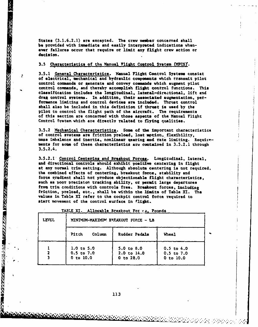
States (3.1,6.2.1) are excepted. The crew member concerned shallbe provided with immediate and easily interpreted indications when-ever failures occur that require or limit any flight crew action ordecision.
3.5 Characteristics of the Manual Flight Control System (MFCST.
3.5.1 General Characteristics. Manual Flight Control Systems consistof electrical, mechanical and hydraulic components which transmit pilotcontrol commands or Xenerate and convey coumands which augment pilotcontrol cornands, and thereby accomplish flight control functions. Thisclassification includes the longitudinal, lateral-direCtional, lift anddrag control systems. In addition, their associated augmentation, per-formance limiting and control devices are included. Thrust controlshall also be included in this definition if thrust is used by thepilot to control the flight path of the aircraft. The requirementsof this section are concerned with those aspects of the Manual FlightControl Systen which are directly related to flying qualities.
3.5.2 Mechanical Characteristics. Some of the important characteristicsof control systems are friction preload, lost motion, flexibility,mass imbalance and inertia, nonlinear %earing and rate limiting. Requir.-meats for some of these characteristics are contained in 3.5.2.1 through3.5.2.4.
3.5.2.1 Control Centering and Breakout Forces. Longitudinal, lateral,and directional controls should exhibit positive centering in flightat any normal trim setting. Although absolute centering is not required,the combined effects of centering, breakout force, stability andforce ,rradient shall not produce objectionable flight characteristics,such as poor precision tracking ability, or permit large departuresfrom trim conditions with controls free. Breakout forces, includingfriction, preload, etc., shall be within the limits of Table XI. Thevalues in Table XI refer to the cockpit control force required tostart movement of the control surface in flight.
TABLE XI. Allowable Breakout For ra, Pounds
LEVEL MINI'MM-MAXIMUV B%kAKOUT FORCE - LB
Pitch Column Rudder Pedals Wheel
1 1.0 to 5.0 5.0 to 8.0 0.5 to 4.02 0.5 to 7.0 2.0 to 14.0 0.5 to 7.03 0 to 10.0 0 to 28.0 0 to 10.0
113
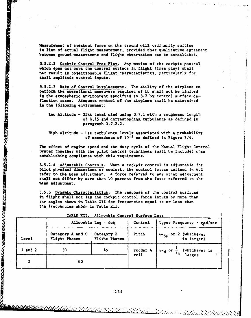
Measurement of breakout force on the ground will ordinarily sufficein lieu of actual flight measurement, provided that qualitative agreementbetween ground measurement and flight observation can be established.
3.5.2.2 Cockpit Control Free Play. Any motion of the cockpit controlwhich does not move the control surface in flight (free play) shallnot result in objectionable flight characteristics, particularly forsmall amplitude control inputs.
3.5.2.3 Rate of Control Displacement. The ability of the airplane toperform the operational maneuvers required of it shall not be limitedin the atmospheric environment specified in 3.7 by control surface de-flection rates. Adequate control of the airplane shall be maintainedin the following environment:
Low Altitude - 25kt total wind using 3.7.1 with a roughness lengthof 0.15 and corresponding turbulence as defined inparagraph 3.7.2.2.
High Alcitude - Use turbulence levels ass6ciated with a probabilityof exceedence of 10-5 as defined in Figure 7/6.
The effect of engine speed and the duty cycle of the Manual Flight ControlSystem together with the pilot control techniques shall be included whenestablishing compliance with this requirement.
3.5.2.4 Adjustable Controls. When a cockpit control is adjustable forpilot physical dimensions or comfort, the control forces defined in 6.2refer to the mean adjustment. A force referred to any other adjustmentshall not differ by more than 10 percent from the force referred to themean adjustment.
3.5.3 Dynamic Characteristics. The response of the control surfacesin flight shall not lag the cockpit control force inputs by more thanthe angles shown in Table XII for frequencies equal to or less thanthe frequencies shown in Table XII.
TABLE XII. Allowable Control Surface Lags
Allowable Lag - deg Control Upper Frequency - rad/sec
Category A and C Category B Pitch wnSp or 2 (whicheverLevel Plight Phases Flieht Phases is larger)
land 2 30 45 rudder & nd or (whichever isroll Rlre
3 60
114
.. .. : ,. , ,. . , ,:.. .. :.,....-. , ..... .. S . . .... ,.. ..
The lags referred to are the phase angles obtained from steady statefrequency responses, for reasonably large amplitude force inputs. Thel&%* for very small control force amplitudes shall be small enough thatthey do not interferte with the pilot's ability to perform any precisiontasks, required in normal operation.
3.5.3.f Control Feel. In flight, the cockpit coatrol deflection shallnot lead the cockpit control force for any fr equency or force amplitude.This requirement applies to the pitch, roll and yaw cnrl. Inflight, the cockpit control detflarction shall not lag the cockpit controlforce by nor* than the angles listed in 3.5.3, for frequencies equalto or loe that those listed in 3.5.3, for reasonably large force inputs.The lag* for very swal control force amplitudes shall not interferewith the pilot's ability to perform precisiou tasks required in normaloperation.
3.5.3.2 Deming. All control system oscillations shall be well damped(see paragraph 3.2.2.1.2) unless they are of such an amplItude, frequencyjand phasing that they do not result in objectionable oscillations ofthe cockpit controls or the airframe during abrupt maneuvers and duringflight In atmospheric environments up to the following:
Low Altitude - 25it total wind using 3.7.1 with a roughness lengthof 0.15 and corresponding turbulence aa defined inparagraph 3.7.2.2.
High Altitude - Use turbulence levelg associated with a probabilityof excoedances of 10-1 as defined in Figure 716.
3.5.4 Auzuntation System*. Normal operation of stability augmntation
and control auttation system and devices shall not introduce anyobjectionable flight or ground handlina characteristics.
3.5.4.1 Performance of Augmentation Syrstems. Perforance degradationof aupientation system caused by atmospheric disturbances and bystructural vibrations shall be considered.
3.5.4.2 Saturation of AugMntation Systems. isits an the authorityof augmentation systems or saturation of equipment shall not resultin oEjectionable flying qualities. In particular. this requirementshall be met during rapid large amplitude maneuvers, during operationnear VS, and during flight in the atmospheric environment of paragraph3.7. Saturation shall not degrade control below an adequate level for
the following atmospheric environvant:
..... .. ~ .. . .
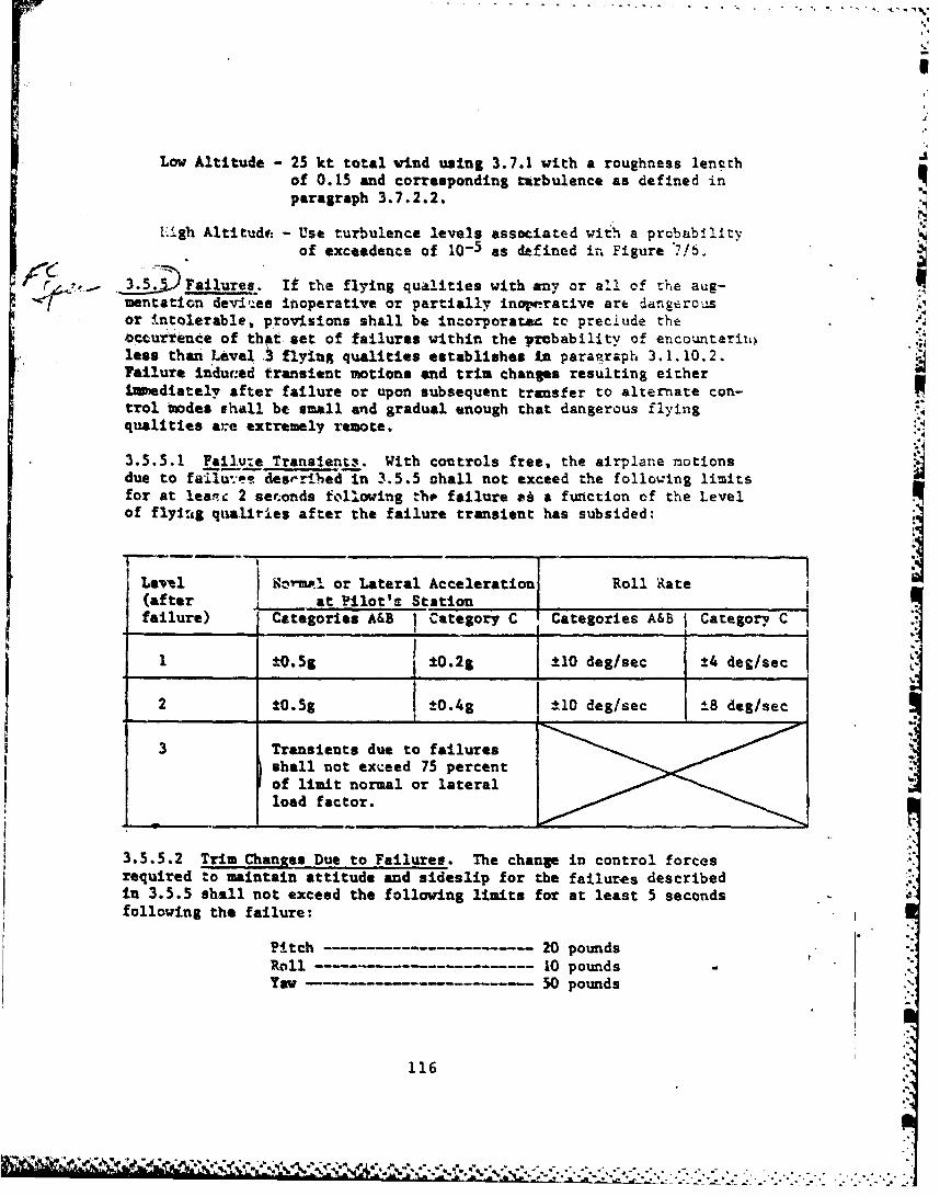
i!
Low Altitude - 25 kt total wind using 3.7.1 with a roughness lenethof 0.15 and corresponding turbulence as defined inparagraph 3.7.2.2.
Uigh Altitud: - Use turbulence levels associated with a prcbabilityof exceedence of 10-5 as defined in Figure 71b.
. 5 Failures. If the flying qualities with any or all of the aug-mentation dev.'es inoperative or partially inop.rative are dangerousor intolerable, provi1sions shall be incorporate" to preclude thebccurtence of that set of failures within the prbability of encounterii..less than Level , flying qualities establishes in paragraph 3.1.10.2.Failure induced transient motions and trim changes resulting eitherIntediately after failure or upon subsequent transfer to alternate con-trol tmodes shall be small and gradual enough that dangerous flyingqualities are extremely remote.
3.5.5.1 Failu:e Transient.. With controls free, the airplane motionsdue to failu-T.:e- desr-ribed In 3.5.5 shall not exceed the following limitsfor at lea.-c 2 seconds following tho failure && a function of the Levelof fly:Lg qualiries after the failure transient has subsided:
Se wm or Lateral Acceleration Roll Rate
(after at Pilot's Stationfailure) Categories A&B Category C Categories A&B j Category C
1 -g 1±O.2g j t10 deg/sec, !4 deg/sec
_ _ _ I _ _ _
2 tO.5g t0.4g 110 deg/sec ±L8 deg/sec
3 Transients due to failures
shall not exceed 75 percentof limit normal or lateralload factor.
3.5.5.2 Trim Changes Due to Failures. The change in control forcesrequired to maintain attitude and sideslip for the failures describedin 3.5.5 shall not exceed the following limits for at least 5 secondsfollowing the failure:
Pitch 20 poundsRoll ------- ------ - 10 pounds ,Yaw - 50 pounds
116A %"
A--. Transfer to Alternate Control Modes. Uste transient motions- wr 17% hanges resulting f rom the in-tentionml engagement or dis-
eagagesent of any portion of the Manual Plight Control System by thepilot shall be small and gradual enough the% dagerous flying qualitiesnaver result.
3-5.6.r Transients. With controls free. the transients resulting fromthe situations described in 3.5.6 shall not emd the following limitsfor at least 2 seconds following the transfer:
Within the Operational *0.05g, norml or lateralFlight Envelope acoalaration at the pilot's station
and tl degree per second roll.
Within the Service *0.56 normal or lateral accelerationFlight Envelope at th pilot's station or ±15 degrees
per scnd roll.
These requirements apply only for Airplane Ninoal States.
3.5.6.2 Trim Chans. The change in control formes required to main-tain attitude and ieslip for the situations described In 3.5.6 shallnot eceed the following limits for at least 5 seconds following thetransfer:
Pitch~ 20 pounds10l1 10 poundsYi,-TM ~---- 50 pounds
These requirements apply only for AiLrplane Uoinl States.
3.6 Additional Characteristics of the Hanual fhIt Control Svsten.
3.6.*1 TrIm Systen. For constant flight path an heading angle thetrimongs devices shell be capable of reducingth pitch, roll and yawcontrol forces to zero for Levels 1 and 2. Fur Leel 3, the untrimdcockpit control forces shall not exceed 10 pjWi for pitch, 5 poundsfor roll, and 20 pounds for yaw. The failures to be considered Inapplying the Level 2 and 3 requirements shall Include trim stickingand ruavay in either direction. It is perminMlbe to meat the Level
* 2 and 3 requirements by providing the pilot with alternate trim machanismsor override capability.
* . 3.6.1.1 Trim for Asvnstric Thrust. For all moltiengine airplanes,it shall be possible to trim the pitch, yaw, mid roll control forcesto zero in constant flight path and heading agle flight with up to
117
*~-v- -- sin:.
wo engines inoperative following amymetric lose of thrust from themot critical factors (3.3.9). For two engine aircraft, this require-Nt applies for one engine inoperative. This requirement defines
Level I In level flight cruise at speeds from the maximum range speedfor the angine(s) out configuration to the speed obtainable with normalrated thrust on the functioning engine(s).
3.6.1.2 Rate of Trim Operation. Trim devices shall operate rapidly qenough to enable the pilot to maintain low control forces underchanging conditions normally encountered in service, yet ncot so rapidlyas to cause oversensitivity or trim precision difficulties under anyconditions. Specifically, it shall be possible to trim the pitch con-trol forces to less then i10 pounds throughout dives required in nora.iservice operation, and level flight accelerations at takeoff thrust
from 250 knots or VR/C, whichever is less, to Vmaz at any altitude, when Ithe airplane is trimad for level flight prior to initiation of themaneuver.
3.6.1.3 Stalling of Trim Systems. Stalling of a trim system due toaorodynarAc loads during maneuvers shall not result in an unsafe con-dition. Specifically, the longitudinal trim system shall be capableof operating during the dive recoveries of 3.2.3.6 at any attainableperminible load factor, at any possible position of the triuming device.
3.6.1.4 Trim System irreversibility. All triing devices shall main-tain a given setting indefinitely, unless changed by the pilot, or bya special automatic interconnect such as to the landing flaps, or bythe operation of an augmentation device. If an automatic interconnector augmentation device is used in conjunction vith a trim device,provision shall be made to ensure the accurate return of the devi~ce
to Its initial trim poasiton on completion of each interconnect oraugmentation operation.
3.6.2 Speed and Fli&bic-Path Control Devices. The effectiveness andresponse times of the fore and aft force controls, in combination witht'ie other longitudinal controls, shall be sufficient to provide adequatecontrol of flight path and airspeed at any flight condition within theOperational Flight Envelope. This requirement may be met by use ofdevices such as throttles, thrust reversers, auxiliary drag devices,and flaps.
3.6.3 Transients and Trim Chanes. The transient and steady statetrim changes for normal operation of such items as throttle, flaps,slats, speed brakes, deceleration devices, dive recovery devices andlanding par shall not iapose excessive control forces to maintainthe desired heading, altitude, attitude, rate of climb, speed or loadfactor, without use of the trimmer control. This requirement applies
11R
* t* . * .
to &lU In flight configuration changes and cominations of changessb under service conditions, Including the of facts of asyistric
operations such ae unequal operation of lending pear, speed brakes,slats Olt flaps.
3.6.3.16 P!ti T Oi anto. The pitch triu changes caused by operationof the wommal nlight control system shell not beaso large that a peak
* pitch control force In excess of 20 pounds Is required under conditionscrpsenmtative of operational procedures. Generally, the conditionslisted In Table KIll will suffice, for determination of compliance withtbis requiremt. With the airplane trimmd for each specific initial
- 4enition, the peak force required to =aIntain the specified parameteresestant, following the specified configuration change shall not exceed *20 pounds for at least 5 seconds following the comleion of the pilotaction Initiating the configuration change. The magnitude and rate oftria change subsequent to this time period shall be such that the forcesare easily trimd by use of the normal triing- devices.* The aboverequirements define Level 1. Tor Levels 2 and 3P' the allowable forcesove Increased by 50 percent. If automatic tria devices are selectable'by the pilot, they shall be Inoperable when shoWin compliance withI
i.a.4 AuxiliarT Dive Recovery Devices. Operation of any awiliaryAevict intended solely for dive recovery shall always produce a positive
increasnt of normal acceleration, but the total normal load factor'hall never exceed 0.8 *L with the controls free.
S. 5 Delete.
119
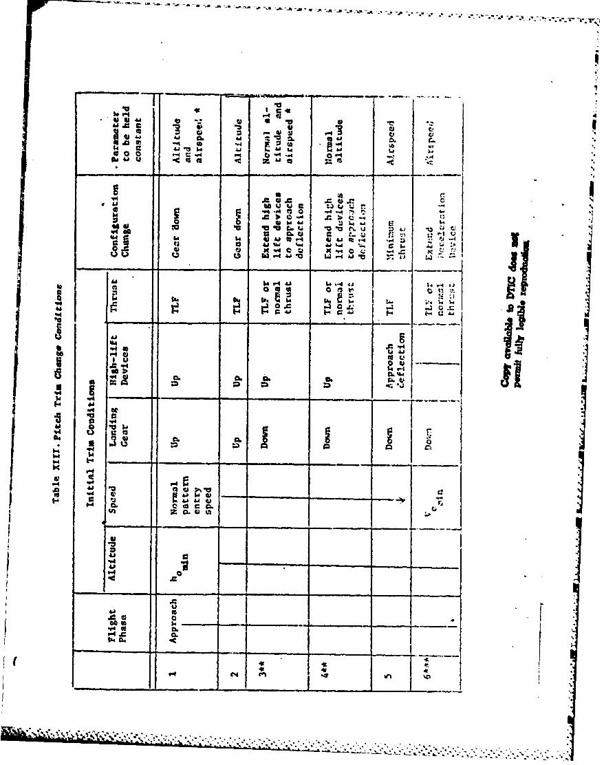
d -W v
a.V p.
* o U) CL Ajz
- =- w - -r -.
c 'a6d.t~ lu4 t
q4U 'U CC tW
b4 4~ 4 .bL. C
cc 'Arit
VA ILIe.
0)
44 ri '04 ' C. C6C~.C
4))
*1.4 'p-6 a -i
___C.r*
-~~ ~ al . u*l**
* 4A.
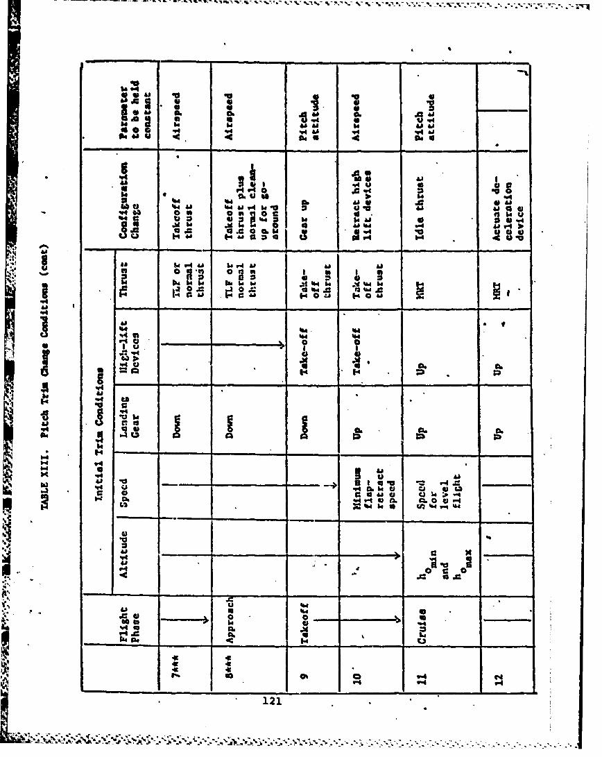
a 0.
4104
Ai
522 0i~4A OM 5 ~ 4'
339
w hi V-40 r-0 "
0i a
V14 Qa
40 i
'44 _ _ _
34 ___121
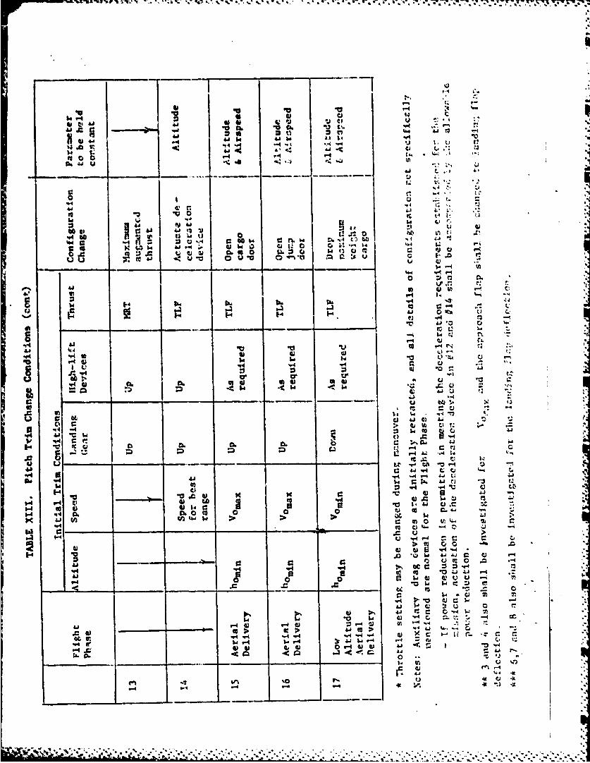
94 "I I
-t4 -4 ... u 1,
t~o V 0 r. 0~ 1'
:3 a -4
o1r. S.
0 V
Lr r.,
14
V44 - N
toi
A i I c Li, C -
-4 q~r4 *4
.00 -- .0 A *11
434-4 4
0. -r "Q tI
'.44
Aa4 to C IL
be 44 *4') -to Lj -4 V-
4-4 C) 4- t c
-4 -- 4 - -4 (1) ;3W .4
41 ed >--- ----. . ...... ..... .....
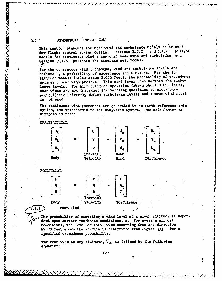
3.7 AThOSPIIER!C CIVIR0'4.,4t
This section presents the =can wind and turbulence 'models to be used.
for 'light co trol systen design. Sections 3.7.1 and 3.7.2" present
models for continuous wind phencnona mean u-Ind and turbuler'c, and
Seetior -1.7.3 'presents the discrete Sust'nodal.
Fur- the continuous wind phenomena, wind and turbulence levels are
9 defined by a probability of excedeneo and altitude. For the low
altitude models (belc: cbuut 3,0)0 fret), the prebability of exceederce
" deftioes a u~an wind profile. This wind level then defines tho turvu-
lauce levels. For high altitude operation (above abcut 3,000 feet),
mean winds are not important for hbndling qualities so cxceedence.robabilit-es 'directly define turbulence levels and a mean wind model
Is not used.
The Cont rTcus wind phenonena are enerated In an eart.h-reterence exssy&tcm, and trans.o. d to the bo&y-exis system. The calculation oftirspeed is then:
F' U 1 Ut[ 1 ]
K Inertial MeanVelocity Wind Turbulenc e
ROTATIO"AL
P C
N InertialBody Velocity Turbulence
7_1 -. ean Wind
The probnbility of eNceedi. a wind le-.ml at a given altitude is depen-dent upon ur-'ace ,-ou,.hres conditionz, z. For average airport
- conditions, the level of &ot%! Vind occur-ing from any directionWi 20 feet a!ove the Surrace is determined from Figure 7/1 for atpecified cxecdencc probability.
The mean wind at any alttude, Vw, is defined by the following
equation:
123
D -, N.
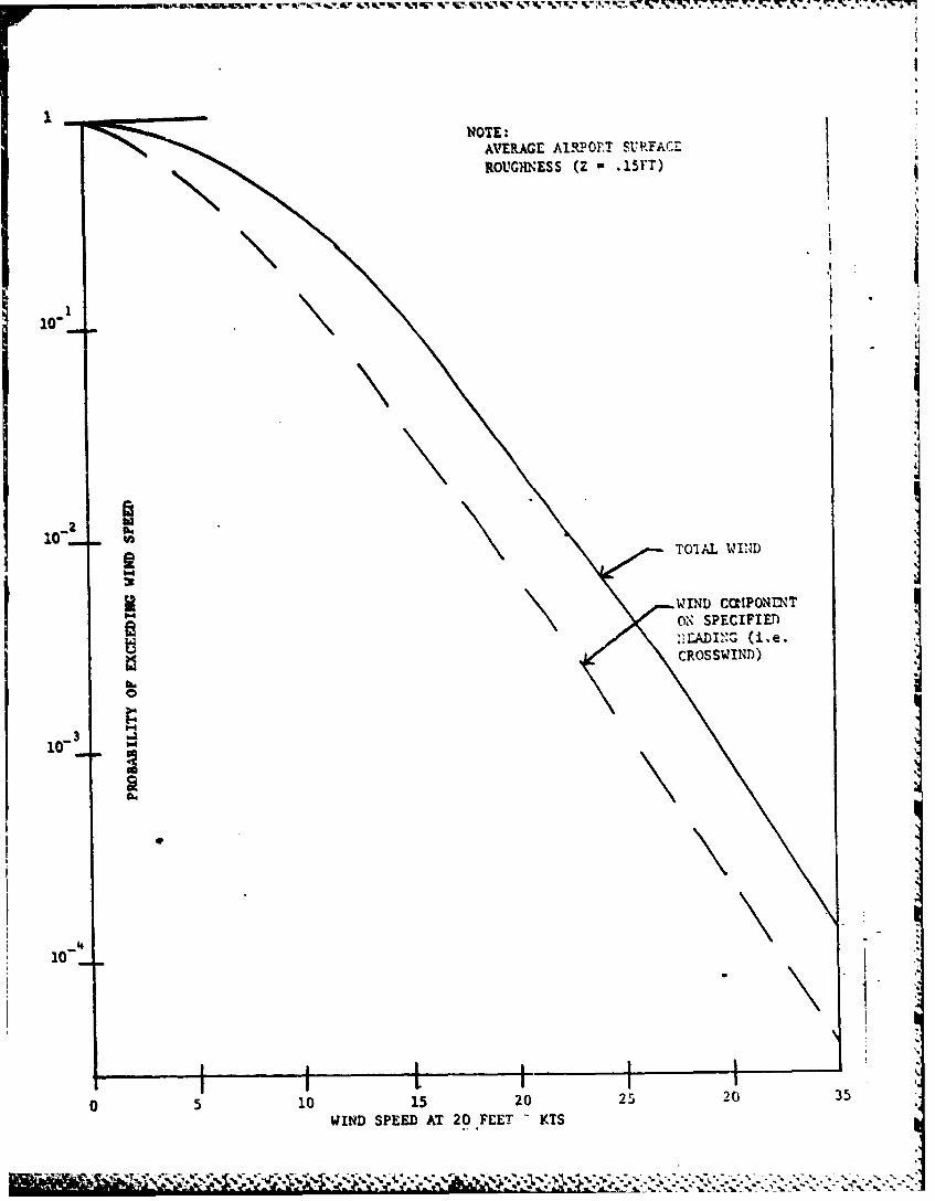
NOTE.AVERAGE A1RPOFT SURFACrROUGHnESS (Z - l5rT)
104
3 TOIAL WIN,'D
WIND CONPONINTON SPECIFIED
CROSSWIND)
10-
05 10 15 20 25 20 3
WIND SPEED AT 20.FEET - KTS
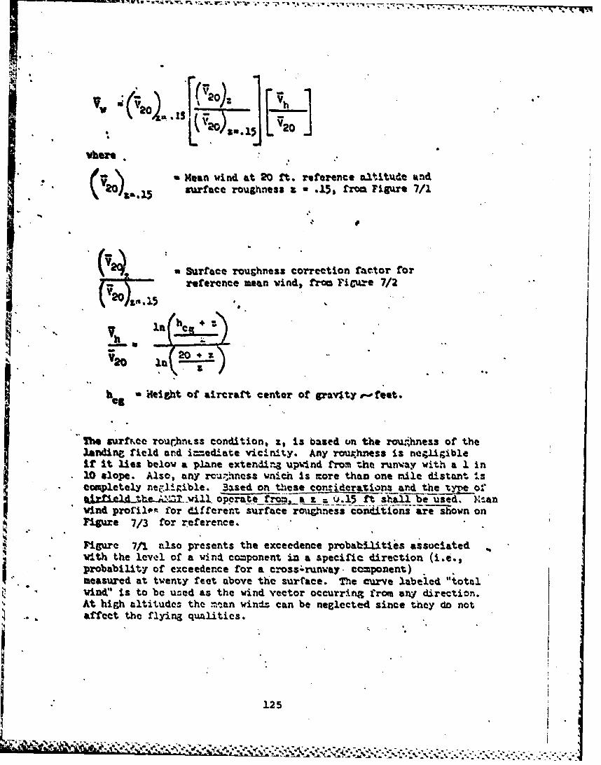
vhhm
S15 ;72 0
vbwre . ,
* . iMean wind at 20 ft. reference aLtitude aknd720)t&. surface roughness a - .15* froa Figure 7/1
.5
(,trface roughness correction factor forreference mean vind, froa FiCure 7/2
V200in
h a Height of aircraft center of prav~ty -eet.
The surf&ce rourhhntss condition, z, is boased on the roughness of thelanding field and i=-iedlate vicinity. Any row.hness is negligiblei it it lies below a plane extendirg upvind from the runway with a 1 in
*10 slope. Also, any rmuahnesx wnich is more than one mile distant IscVpletely nel iiible. 3sed on these conriderazions and the tyre of" rl~ed the-A= will oppre_ __ . f shall be used. Xtanwind pro'illem for different surface rouginess conditions are shown onFigure 7/3 for reference.
Figure 7/11 P.lso presents the exceedence probabilities associatedwith the level of a vind co=ponent in a apecific direction (i.e.,i probability of exceedence for a Cross3;runway - ccponent),measured at twenty feet above the surface. The curve labeled "total
vind' is to be used as the wind vector occurring frova any direction.* At high altitudes the =tan windz can be neglected since they do not
affect the flying qualitics.
125
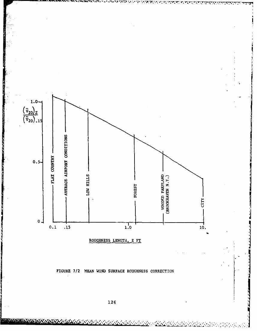
F 1.0-
( 2o) Z
(V20).15
0.5-4
Hz
0.0
0.5 .1 10 0
ROGNS ENTZFIGUR 7/ ENWNiUFC RUHESCRETO
12
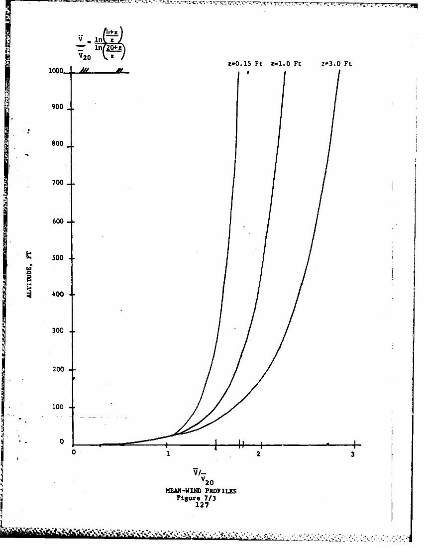
V . I- 1n 20+z\V20
900z-0.15 Ft z-1.0 Ft z-3.0 FtZ 1000- -AL-
~900
800
700
600
500
400
300
200
100
0 1 2 3
i V20
Sj MEAN-WIND PROFILES
Figure 7/3127
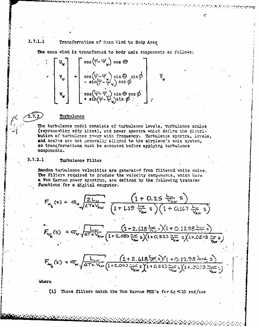
* .•--- .
C
3.7.1.1 Tramform-tion c. .1',Van Wind to Body kxes
The = eti wind iz transforv.ed to body axis co=ponent. as follows:
'~1Cos C ~~CosVw co-'- si c s in
U s-, J&,- c,, G o: w
WI C ' 0 (4 - in;. o e Cos>
+l
47 T .rbulencc
i .(r: " T De turba,.ence model consists of tulbulence leveLs, turbulence scales(representin7 ed,'ze sizes), and ower specta wnch define the dA.,tri-bution of t '.... ..ce :wer with frequency. Turbulerce spectra, lvelis,and zcale.s.zare not general!y al; ;n to the airpiae's mY.±s system,to tratz, or..atiuns =ast be executed before apply-inr turbulencecomponents.
3.7.2.1 Turbulence Filter
SRutdom turbulence velocities are generatr froem filtercd white noise.The filters required to produce the velocity components, which ,,,ea Von YLr..zn p.ower sr.ectr%,, are defined by the fo)1loin transferfunctions for a diaital co=puter.
U4 C') U TI]v, __ S + O. 1_ __7_v_---.
+t p, Lj s)" +- ,, 1,.. ,. -," .•_
t
w,,,( )= L"r, ,. ( ~a .4I'8.Yi + QI < 3L.t-..s .
vhere
(L) These filters match the Von KarrAn PSD's for &L i'10 rad!eac
Lau I i ,
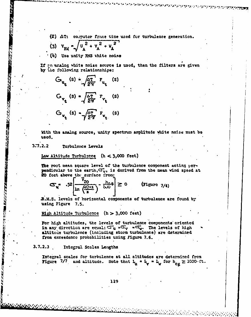
(2) AT: co--. ar f-.r.e ti-e u.-d for turbulence generation.
(3) VR4O U2 A +mL
" (4) use unity saS %to noise
&log white noise so.rce is used, then the filters are givenby "s rollowins relatiorhipe:
3... TTln e
Lov Altitu/de Tarbu!--re (h < 3s)0 feet)
l The root' meatn square level of the turbixlence component actir3 per-
pendicular to the earth,(:Y., is derived from the mean wind speed at20 fet above th,. surface from:
WiM.t. level of horizontal components of turbulen e nfound by
usin Figure 7.5.
High Altitude Ttxrbulence (h > 3,000 feet)
,or high altitudes, the levels of turbulence components ariented
,: ~in any direction are e oual: -u "'-, •The levels Of highnaltitude turbulence (Unclu'ins storm turbulence) are determined tfom exceedence probabilities usig Figure. 7.6.
3.7.3 Intel.-ta Scales Lenths
Intter'Sral scales for turbulence at all altitudes are determined fromigh 7 aAd atiituee. oe that L( 3,04 for et )0t.
129
Lk AC
"or h-, a. tlen
-in -ny.directio ar,..,a ,, .,-,T,-e.le..els.of..hg.
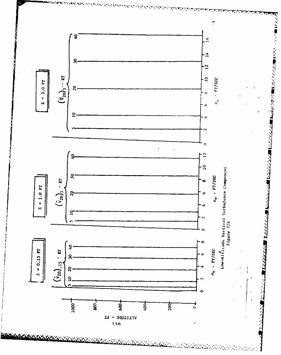
Q co
UU
'4.1
I.
LON.
C-4
CD 0
304 -i
irn
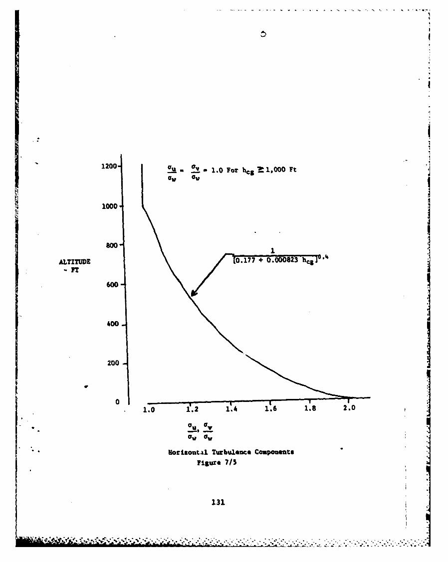
1200
I
1OR 0 Ua 5 1.0 For hc M1,000 Ft
1000
Boo
ALTITUDE 0.177 + 0.00082 3eT
I
400
200
0
,'u OI
*W O O
* Horizuontal Turbulence Components
Figure 7/5
131
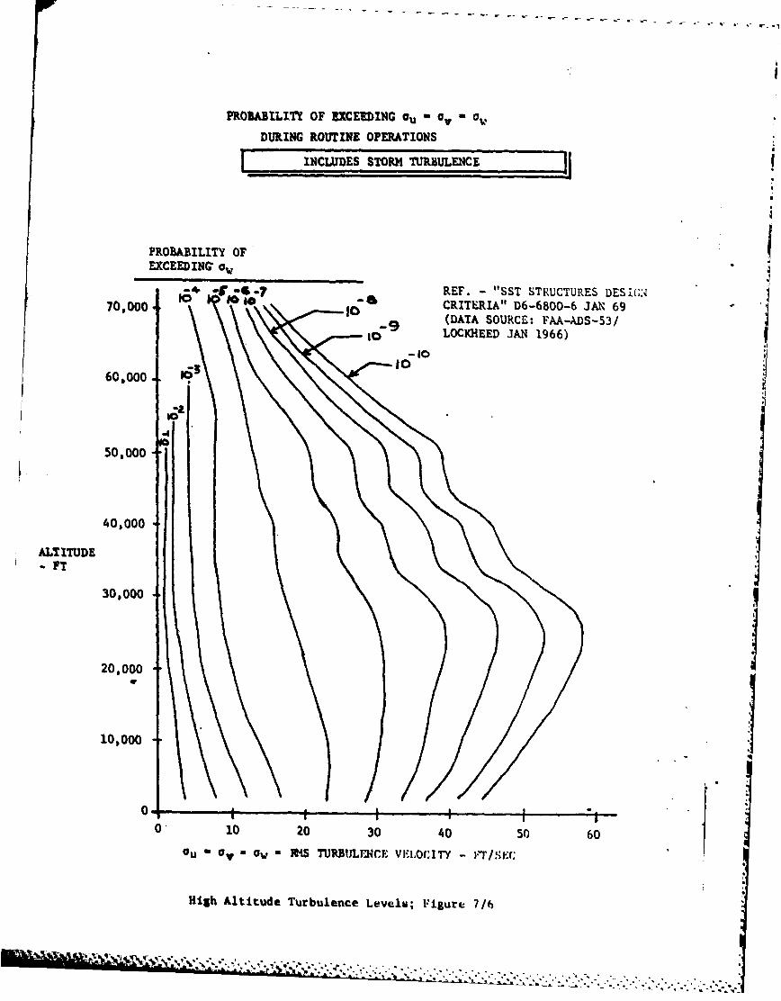
PROBABILITY OF EXCEEDING Qu -, a,
DURING ROUTINE OPERATIONS
INCLUDES STORM TURBULENCE
PROBABILITY OF
EXCEEDING ow
REF. - "SST STRUCTURES DES IGN70,000 CRITERIA" D6-6800-6 JAN 69
-9 (DATA SOURCE: FAA-ADS-53/--- tLOCKIHEED JAN 1966)
60,000 163
50,000
40,000
ALTITUDE
FTI30,000
20,000
10,000
04 I I0 10 20 30 40 50 60
u Ow aw = lRS TURBULENCE VEI.OCITY - I"T/Sk.r;
High Altitude Turbulence Levels; Figure 7/6
%...... . ". "-
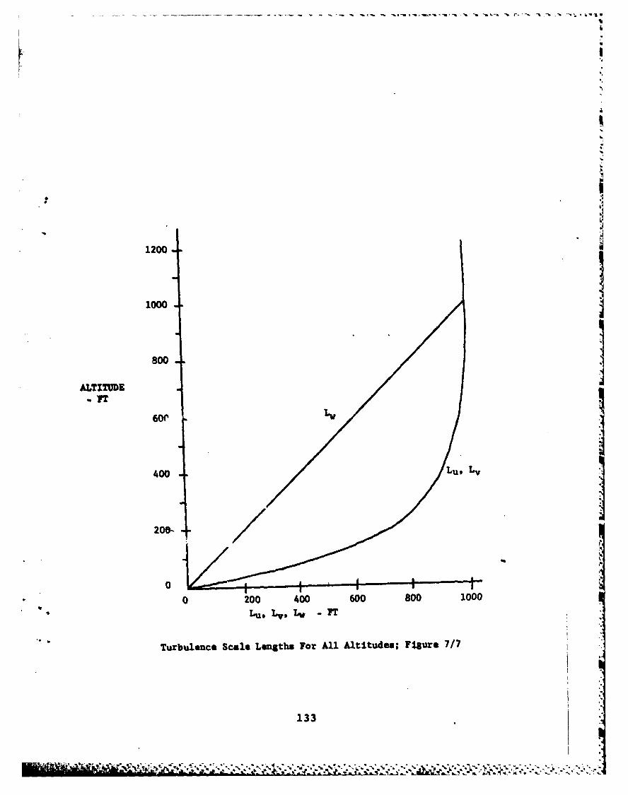
1200
1000
800
ALTITUDEIT
400
2W t
0 200 400 600 800 1000
Lu, - L, v FT
Turbulence Scale Lengths For All Altitudes; Fsgure 7/7 I
133
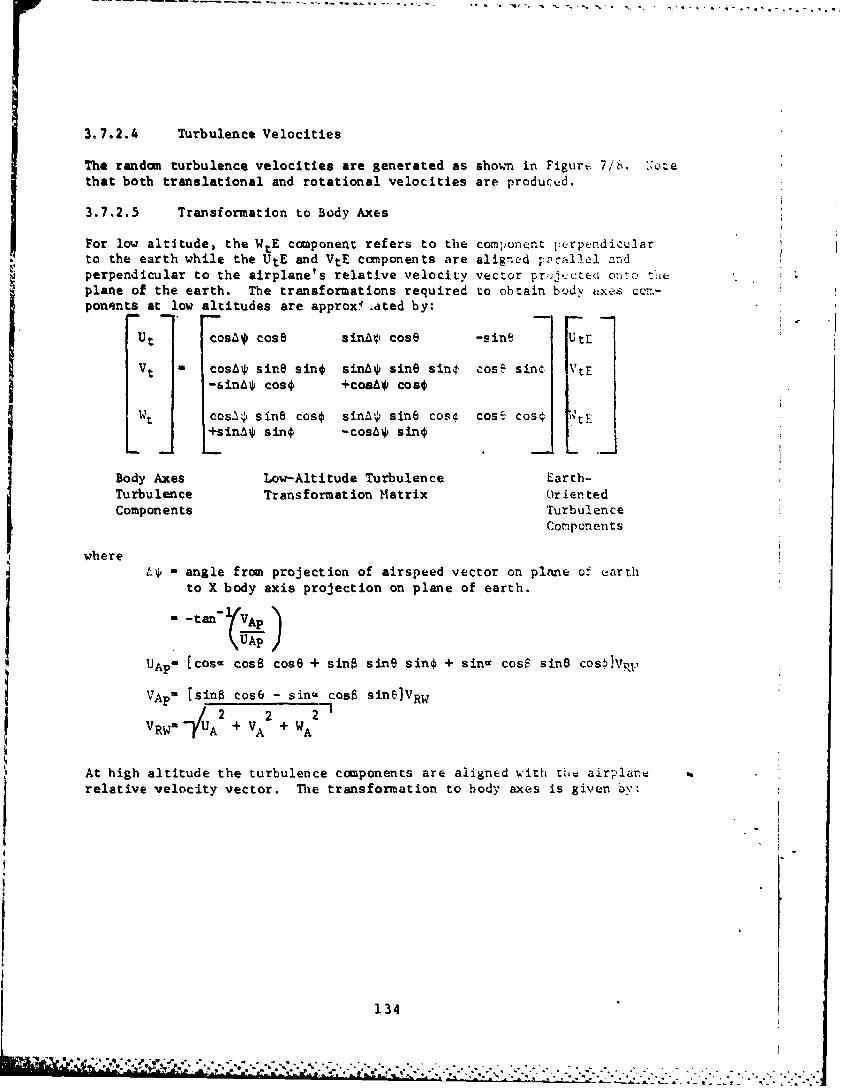
3 7.2.4 Turbulence Velocities
The random turbulence velocities are generated as shown in Figurt. 7/ti. :oCethat both translational and rotational velocities are producvd.
3.7.2.5 Transformation to Body Axes
For low altitude, the WtE component refers to the comlJonent pi rpendicularto the earth while the UtE and VtE components are aligned pprallel andperpendicular to the airplane's relative velocity vector pr:J,.cted ort.o t'i(plane of the earth. The transformations required to obtain bod\ axes cC!-ponents at low altitudes are approx.ated by:
Ut cosL* cos8 sina4, cos@ -sine UtE
Vt - cosSv sine sino sin&L sine sink cosE sine IVtE-sin&* coso +coaA* cosL
i Wt cos', sine cos€ sin'. sine coso cosS cos€.+sin* sin4 -cosA* sin
Body Axes Low-Altitude Turbulence Earth-Turbulence Transformation Matrix OrientedComponents Turbulence
Components
whereL- - angle from projection of airspeed vector on plane of Qarth
to X body axis projection on plane of earth.
= -tan- (VAp
UAP = [cos= cosS cose + sine sine sin + sina cosQ sine cosflVP.
VAp = [sine cos6 - sina cosS sine)VRw/2 2 2'u
VRW= U A + VA + WA
At high altitude the turbulence components are aligned with tht airplarodrelative velocity vector. The transformation to body axes is given by:
134
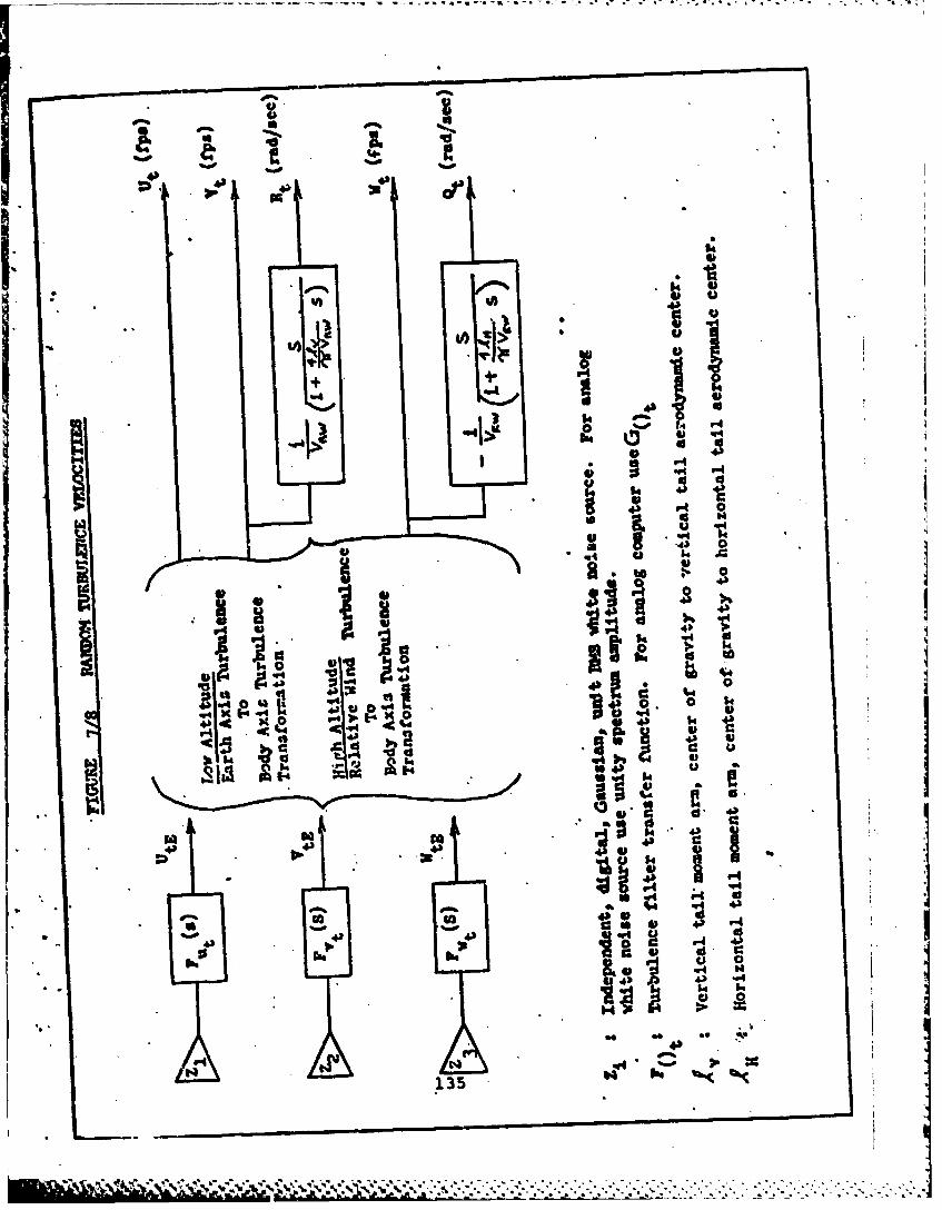
4W,.5 Lo
W iK
14s
ID to
0*0
o- 0o o
r4 464
r 4S~
0v
shehe
.644
P1135

46 4
t
HThTrbirlnce T u na
componen~ts op--t
3.7.3 Discrete 0 1'.t AialvY-is
The discrete Cust =odel descTibed below is to be used in hanUinaqualities a:-!ysis: only -
Ane aircraft shal be contro-a'ble (within struactural li-Its) whern
sub'.:tti to -..- :, iscrete Susts. A, conservative estJ--tc ofthe most extreme t =o be cnccuntercd during the fleer liife-time shall be used.
The discrete Gust model may be uscd for any of the three Cast-vcczitycomponents. !be discretc gust has the "I - cosine" shape;
0 0
cot o O<x <2d
0 , x> 2d
vherod dd, or d
V v , or v.
y -
_ft/v ec
*-------------
0 0 d ~ZdW % 'IC, t
Sover~~'1. Qf D~ , ~ leued 3h~ee o thtt the ! lt 12
LU j find4 L. cre obtained fromi Figure 7/7
V7~ tft Cire n Secticm 3.7.2.2
AS
taw 1 3
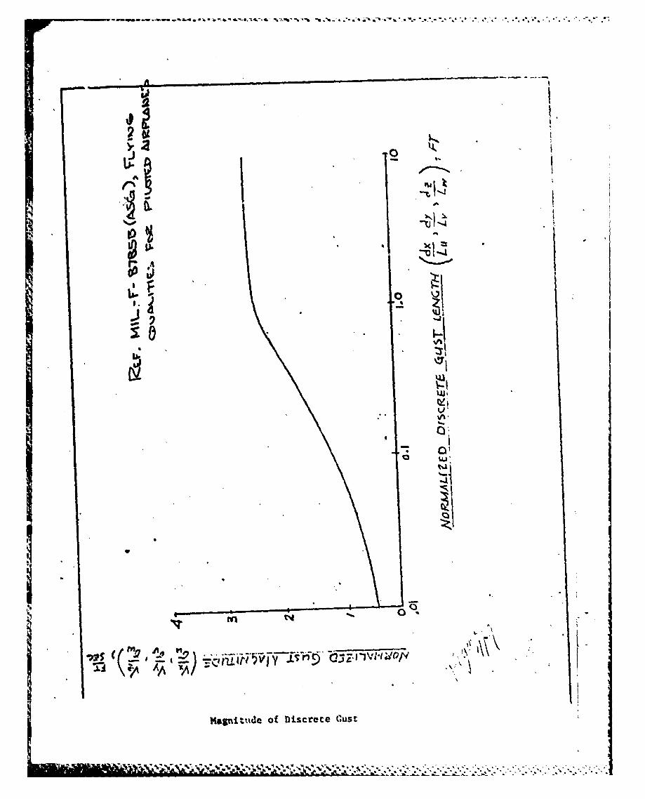
-' - -s._ - .~ ,. "* * * . .. . C - -
IU]
.j'
"V'
* o
.i .
* oI
- CI
Nal~tt~e o D scrce lus
i ,i u t :,.: -,-,- % ., , - -,- ,... ..- .. -. -.-, -..-,.. .... -.. .- ..
S. Preovaation for Delivery.
5.1 Section 3 to not applicable to this specification.
6. Notes.*
6.1 In'te-hd Use. This specification contains the flying qualitiesrequiemts for the C-IA and foru one of the bases for determinationby the procuring activity of airplane acceptability. The specificationserves as design requirements and as criteria for use in stability andcontrol calculations, analysis of wind-tunnal test results, flyingqualities slmlation taste, and flight testing ad evaluation. TherequIreumets are Intended to assure adequate flying qualities regardlessof deslig slpeuantation or flight control system mechanization. Tothe extent vosslble, this specification should be met by providing anInherently sood basic airframe. Where that in not entirely feasible, orwhere Inordinate oenalties would result, a uchanie is provided hereinto assure that the flight safety, flying qualities end reliability aspectsof dependence on stability augmantation and other form of systemcoulication will be considered fully.
I
b1
It
:13
___:. _-. -,. '.,..-,',-.:,-.. ,-, -.. . .. .-

6.2 Definitions. Terms and s,-nbols used Lhroughout this specification are defined
as follows:
6.2.1 General.
- - wing area
s - Laplace operator
q - dynamic pressure
- mean 3ea level
T2 - time'to double amplitude T.,-. for.
T2 - -.693r for first-order divergences.
Airplane Normal the nomenclature and format of table XV snall le seStates in defining the Airplane Norma' States (3.1
3erviee ceiling -altitude at a given airspeed at which the rate cf cLi-tis 100 ft/min at stated weight and engine .thras'
, ombat ceiling - altitude at a given airspeed at which rate of limb is'500 ft/min at stated weight and engine thrust
Cruising ceiling - altitude at a given airspeed at which rate of climt is300 ft/min at NRT at stated weight
hax - maximum service altitude (defined in 3.1.8.3)
' h- - maximum operational altitude .(3...7)
69
Copy cvailcble to DTIC does notpermit fully legible reproduction
(140
"' '
. " ' ' " -", , . ,
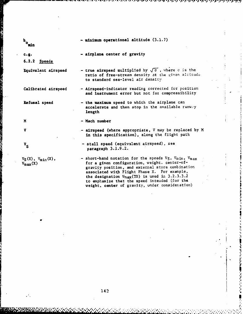
h - minimum operational altitude (3.1.7)aoMin
c.g. - airplane center of gravity
6.2.2 Speeds
Equivalent airspeed - true airspeed multiplied by J-a where o -is theratio of free-stream density at the riven alriLudLto standard sea-level air density
Calibrated airspeed - Airspeed-indicator reading corrected for positionand instrument error but not for compressibility
Refusal speed - the maximum speed to which the airplane canaccelerate and then stop in the available runw,,vlength
M - Mach number
V - airspeed (where appropriate, V may be replaced by Min this specification), along the flight path
VS - stall speed (equivalent airspeed), seeparagraph 3.1.9.2.
VS(X), Vmin(X), - short-hand notation for the speeds VS, Vmin, Vmax
Vmax(X) for a given configuration, weight. center-of-gravity position, and external store combinationassociated with Flight Phase X. For example,the designation V.ax(TO) is used in 3.2.3.3.2to emphasize that the speed inteuded (for theweight, center of gravity, under consideiati.on)
,..
142
S5' " ,;, . ,' ,: r , . - <,,:. . " ;- ,, ,- , . ..-,,- - , - .. -. . . - - - . , .. ,. . .. . . .. . .. . .p
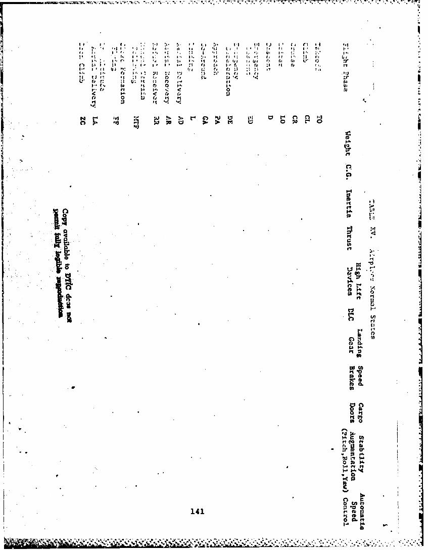
wc.%rntw~t ~ -.-*vi.* - I- -. - - W-7 W- wwWi ~ ~ ~ C~4 -
Ij 1%
P.). .
IS~~~~~~~~~~r I' I ' 'ip . i IISD fC l. ,
tQ :'o r4 ''3 1. 0I~ a i aS 5 a ~ . . .I.2 i.n' . ' ' ; a .3. *. U " a .
a: 5. a* a. a: '. ~* c. ~ . ag s ' ~ I'. ,~ ( It I*.1l 6
.'~: a'* a'i 'a :I " * I. feqe iu~j C' Sa te U 1)tX
hi ~~ ~ ~ ~ ~ ~ ~ ~ ~ ~ ~ t Faa': s i**,. e asr ' 5* U t.
!I t at Ir. .. o~ '' 'LO
'40~~~ 0 4r '
aT . Io -
1411
9-0
voo"K'I
.'V7
is VmAx for the configuration associated with thetakeoff Flight Phase. This is necessary to avoidconfusion, sinze the configuration and Flighc Phasechange from takeoff to climb during the maneset. .
Vtrim - trim speed
Vend - speed for maximuji endurance 4VL/D - speed for maximum lift-to-drag ratio
VR/c - speed for maximua rate of climb
Vrange - speed for maximum range in zero wind conditions
- high speed, level flight, normal rated thrust
V MT - high speed, level flight, military rated thrust
VHAT - h1h spead, level flight, maximum augmented thrust
V1 V - meximum service speed (defined-in 3.1.8.1)
Vain a minimum service speed (defined in 3.1.8.2)"
Vo - maximum operational speed
V - minimum operational speed%in
6.2.3 Thrust
TL7 - thrust for level flight
I- normal rated thrust, A ich to the maximum thrustat which the engine ca.% be operated :ontinuously
MRT - military rated thrust, wbich is the maximum thrustat which the engine can be operated for. a specified
... 143
MAT - maximum augmented thrust: maximum thrust, augmentedby all mans available for the Flight Phase
Takeoff thrust - maximum thrust available for :akeoff
6.2.4 Control prne,,rs
Elevator, aileron, - The stick or wheel and rudder pedals manipulated byrudder controls the pilot to produce pitching, rolling, and yawing
at nts respnctivly; the cockpit controls plto
Elevatr control Component of applied force. exerted by the pilot an
force the cockpit control, in or parallel to the plane ofsymmtry, acting at the center of the stick grip orwheel in a direction perpendicular to a line betweenthe center of the stick grip or wheel and the stickor uontrol column pivot
Aileron control For a stick control, the component of control forceforce exerted by the pilot in a plane perpendicular to the
plsne of symmetry, acting at the center of the stickgrip In a direction perpendicular to a line betweenthe center of the stick grip and the stick pivot. Fora wheel control, the total moment applied by the pilotabet the wheel axis in the plane of the wheel, dividedby the average radius from the wheel pivot to thepalot's grip.
Rudder padal force Difference of push-force components of forces exertedby ;he pilot on the rudder pedals, lying in planesparallel to the plane of synotry, measured perpen-dicular to the pedals at the normal point of applicationof the pilot's instep on the respective rudder pedals
Control surface - A device such as an external surface which is pos.Lionedby a cockpit control or stability augmantation system to Iproduce aerodynamic or jet-reaction type forces forcontrolling the attitude of the airplane. As used inthis specification the elevator surface, aileronsurface, and rudder surface are the control surfacesor devices which are controlled by the stick or wheel 9and rudder pedals, and automatically by stabilityaugmentation systems.
(144
%r
A.e
Diret normal - A device producing direct normal force for thet ee control pimar7 purpose of coetrolling the flight path
or the airplane. Direct normal force control iste descriptive title given to the concept ofdirectly modulating the normal force an an airplaneby changing Its lirting capabilities at a constantangle of attack end constant airspeed or by control-ling the normal force component of such items asJet exhaustse
Costrol power - Effectivenets. of control surfaces in applying Vorcasor mcnents to an airplane. For example, 50% of
available alleran control power is 501 of the a.1a0Mralling =ment that is available to the pilot vithallowable aileron control fr:e.
. Lotnitudinal .armeters
CSP - damping ratio of the short-period oscillation
Wasp - md&qWd natural frequency of the sbort-periodoscllation
Cp - "tmpag ratio of the phugoid oscillation
CORP - undamped natural frequency of the phugoid oscillation
I - normal actelerati-n or normal load factor, measuredat the C.g.
Vt - symetrical flight lA.Lt lod factor for a givenAirplane Normal State, basd on structuralconiderat ions
1 wox, ~mrn - maxims and minimiasn Seryi*e loa factors
145
g "
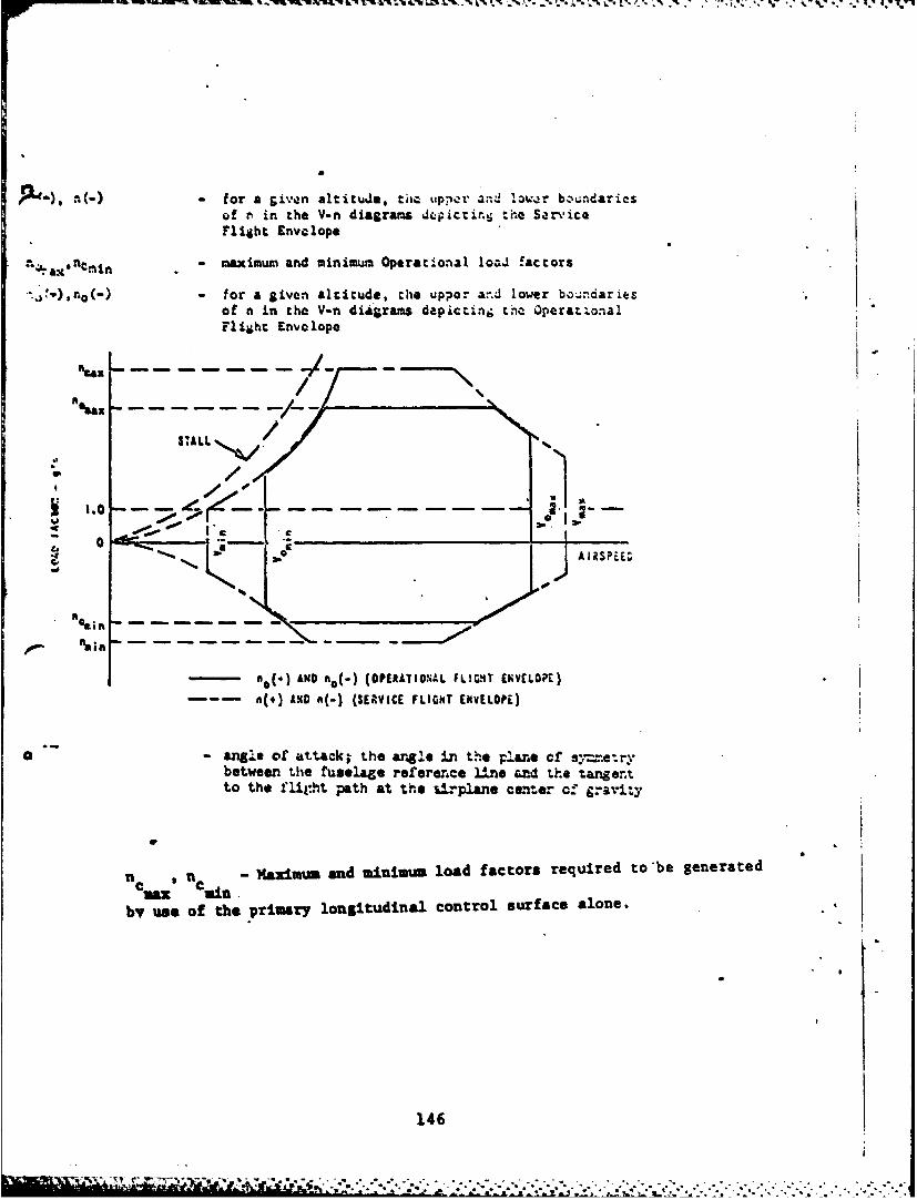
P"). a(-)- for a given altitude, t uppr and lwrof r in the -n diagrams depicting the ServiceFlight £nvclope
? . n tmin - aximum and minimum Operational 1oaJ !actors
' .: ),no(-) - for a given altitude, the upper ar.d lower bo.;ndariesof n in the V-n diagrams depicting thn OperatzonalFlight Envelope
%an
.1 'aA-
.000
AIRSPEE
- 0(4 ) AND ho(-) (OPERATIONAL FLIGHT EKVELOPE)
a(*) AND n(-) (SERVICE FLIGHT ENvELOPi)
S-angle of attack; the argle in the plane of s.-etrvbetween the fuselage ref~erence line and the tangenrtto the flight path at the Uirplane cemer cf gravity
n .-MaximuM and minimum load factors required to be generated
by use of the primary longitudinal control surface alone.
146
.. C . •
- the stall angle of attack at constant speed for theconfiguration, weight, center of gravity positionand external-store combination associated with agiven Airplane Normal State; defined as the lowestof the following:
a. Angle of attack for the highest steady loadfactor, normal to the flight path, that canbe attained at a given speed or Mach number
b. Angle of attack, for a given speed or Mach ntmber,at which uLcomanded pitching, rolling, oryawing occurs (3.4.2.1.2).
c. Angle of attack, for a given speed or Mach number,at which intolerable buffeting is encountered.
d. An arbitrary angle of attack allowed by 3.1.9-2.
CLstall - lift coefficient at a defined above.
n/s - the steady-state normal acceleratiod change per unitchange in angle of attack for an incremutal elevatordeflection at constant speed (airspeed and Mach number)
F./n - gradient of steady-state elevator control force versusn at constant speed (3.2.2.2.1)
y- climb anle , positive for clmbiLng flight !1 Vertical sueed
True airspeed
L - aerodynamic lift plus thrust component, normal tothe flight path
6.2.6 Lateral-directional parameters
aAS - displacement of the ailert-. control stick or wheelalong its path
- first-order roll mode time constant, positive for %stable mode .,
T S - first-order spiral mode time constant, positive for' stable mode
/
Ca0 * - undamped natural frequency of numerator quadratic of; /6AS transfer function
147
- daMping ratio of numerator quadratic of #/Stransferfunction
a undaviod natural frequency of the Dutch rolloscillation
- damping ratio of the Dutch roll oscillation2f
- damped period of the Dutch roll, 7 " d!fJ
bank angle measured in the y-a plane, between they-axis and the horizontal (6.2.1)
- bank angle change in time t, in response to control
deflection of the form given in 3.3.4
. roll rate about the Y,-axis (6.2 1)
f a measure of the ratio of the oscillatory componentAV of roll rate to the average component of roll rate-V following a rudder-pedals-fre step aileron control
command :
'pg p, tf3 2 -p
0.2: _ - C ____
where Pl , P2 and P3 are roll rates at the first.second and third peaks, respectively.
#05C a mmasure of the ratio of the oscillatory componentof bank angle to the average component of bank angle
#AV following a ruddar-pedals-fre, impulse aileron
control command:
.2 0 62f 0, 0 ~0
- 0 I V
where *I * and are bank angles at the first.,second and third peaks, respectively.
(.
148
i *'
BO - sideslip angle at the center of gravity, anglebetween undisturbed flow and plant of symmetry.( Positive, or right, sideslip corresponds to incidentflow approaching from the right side of the plane ofsymnotry.
he J maxsz - maximum change in sideslip occurring within 2 secondsmax or one half-period of the Dutch roll, whichever is greater,for a step wheel-control comand.
k - ratio of "commanded roll performance" to "applicableroll performance requirement" of 3.3.4 or 3.3.4.1, where:
a. "Applicable roll porformace requirement",(4t) requirement, is determined from 3.3.4 and3.3.4.1 for the Class, light Phase Categoryand Level under considers:ion.
b. "Commended roll perforce", (4*) command, isthe bank angle attained L the stated time fora given step aileron cind with rudder pedalsewployed a specified In 3.3.4 and 3.3.4.1
k . (t) reqniremant
- time for the Dutch rolltscIlation In the sideslip( response to reach the n local maxi== for a rljthtstep or pulse aileron-control eounand, or the nthlocal minimum for a left ce d. In the event astep control Input cannot be accomplished, thecontrol shall be moved as abruptly as practical and,for purposes of this definidm, tim shall bemeasured from the instant the cockpit control deflec-tion passes through half the =Wltude of thecommand value. For pulse mluts, time shall bemeasured from a point halfimy through the durationof the pulse.
149
- -,
- ' .. ." ..r*
, i ,-, _ . ,. , q ,, :, - - -- f
'" "
- phase angle expressed as a lag for a cosine representation ofthe Dutch roll oscillation in sideslip, where
-60td no + (n-1)360(degrees)
where n as in tno aboyt
- at any angle between roll rate and sideslip in the free UutchB roll oscillation. Angle is positive when p leads by an
angle between 0 and 1800
I/ - at any instant, the ratio of amplitudes of the bank-angle andsideslip-angle envelopes in the Dutch roll mode
Since several oscillations of the Dutch roll are required to measure theseparameters, and since for proper identification large roll rates and bankangle changes must generally be avoided, for flight test, step aileron inputsshould generally be small. It should be noted that since *o is the phaseangle of the Dutch roll component of sideslip, care must be taken toselect a peak far enough downstream that the position of the peak is notinfluenced by the roll mode. In practice, peaks occurring one or two rollmode time constants after the aileron input will be relatively undistorted.Care must als be taken when there is romping of the sideslip trace, sinceramping will displace the position of a peak of the trace from the correspondingpeak of the Dutch roll component. In practice, the peaks of the Dutch rollcomponent of sideslip are located by first drawing a line through the rampingportion of the sideslip trace and then noting the time at which the verticaldistance between the line and the sideslip trace is the greatest.
I VII 'OIN
I~"' ~ *~'iq%. .
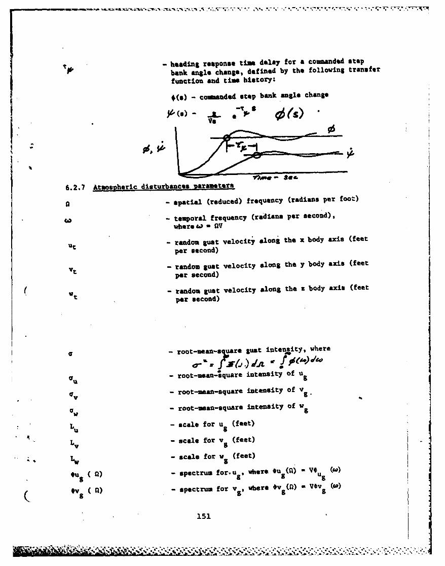
- heading response tim delay for a coumanded step
bank angle change, defined by the following transfer
function and time history:
*(s) - coumnded step bank angle change
vs
6.2.7 Atmospheric disturbances Parameters
- spatial (reduced) frequency (radians per foot)
L) - temporal frequency (radians per second),
where W - OV
ut - random gust velocity along the x body axis (feet
per second)
vt - random gust velocity along the y body axis (feet
per second)
Wt - random gust velocity along the & body axis (feet
per second)
- root-mean- 7 ;are gust intensity, where
oo-"a--.) i o
Ou - root-mean-square intensity of v.
0v w- root-mean-square intensity of v .
ov - root-mean-square intensity of wg
Lu - scale for ug (feet)
Lv - scale for v (feet)
" -W - scale for w (feet)
u ) - spectrum foru , where Ou (l) - V#u M
( V () - spectrum for v5, wbere *v g(r) - V~v (g.)
151--
OW( -spectru for v, where w(l)- Vow()
- eneralized discrete gust velocity, positive alongthe positive airplane. body axes, u - x, y, Z (CN.:-per second) t ,,
d. - generalized discrete gust lee ,th (always positive)2 , 7. a (feet)
152
I.
' 'S
!(
- 152
. -
REFERENCES
1. FYLiut Qualities of Piloted Airplanes, Military SpecificationMIL-F-8785B, Amendment 2, 16 September 1974.
2. Fliaht Control Systems - Desian. Installation and Test of PilotedAircraft, General Secification for, Military SpecificationMIL-F-9490D (USAF), 6 June 1975.
3. Flying qualities of Piloted V/STOL Aircraft, Military SpecificationMIL-F-83300, 31 December 1970.
4. Scott, b. C., Hynes, C. S., Martin, P.W., and Bryder, R. B.,Progress Toward Development of Civil Airworthiness Criteria forPowered Lift Aircraft," FAA-ID-76-100, May 1976.
5. Franklin, James A.., et &l, "Recomendations for Airworthiness andFlying Qualities Specifications for the Air Force Advanced MediumSTOL Transport Aircraft", NASA Anes Research Center letter,June 1976.
6. Flight Dynmics Analysis, "Airplane Failure States Flying QualitiesStatus (Paragraph 3.1.10.2 of MIL-F-8785B) Design ValidationReview", North American Rockvell, Document No. TmD-2-1122,29 September 1972.
7. Allison, R. L., Mack, M., and Rumsey, P..C., "Design EvaluationCriteria for Comercial STOL Transports", NASA CR-114454, Jume 1972.
8. "C-14 Flight Control System Design Requirements and Objectives",The Boeing Copany, Docament No. D162-12058-1 TH, 29 January 1976.
9. Neal, T. P., and Smith, R. E., "An In-Flight Investigation toDevelop Control System Design Criteria for Fighter Airplanes".Vole I and II, AFFDL-TR-70-74, December 1970.
10. Wasserman, R., Mitchell J. F., "In-Flight Simulation of MinaumLongitudinal Stability for Large Delta-Wing Transports inLanding Approach and Touchdown", Vol r, AFFL-T-72-143, February1973.
11. Snyder, C. T., et al, '"otion Simulator Study of LongitudinalStability Requirements for Large Delt# Wing Transport Airplanes
9 . During Approach and Landing with Stability Augmentation SystemsFailed", NASA TM X-62, 200, December 1972.
12. Drake, D. E., et al, "A Flight Simulator Study of STOL TransportLateral Control Characteristics", FAA-R-70-61, September 1970.
153k*
13. Stability and Control Branch, F lying Qualitiles of Lhe .-lode2.DC-10-10CP Compared with MIL-F-I785B(ASG)"', Dougla6 AircraftCompany, MDC-J5916, 21 March 1973.
14. Chalk, C. R., et a!., "Background Informatior, and Plser Guichefor MIL-F--8785B(ASG)", Military Specification - F'lyinE Qiualiui(-sof Piloted Airplanes", AFFDL-TR-69-72, August 1969.
.15. Anon, "V-STOL H~nlnI Criteria and Discusshin ,
577-70.
16. Barr, N.M., Gangass, D., Schaeffer, R. D., "Wind MIc dvlt forFlight Simulator Certification of Landing and Approacit Guidanceand Control Systems", FAA-RD-74-206, Decemb-er 197'".
154

![AMST Course Brochure Spring 2017 EDITED 4[1]amst.fullerton.edu/AMST Course Brochure Spring 2017.pdf · With the concept of culture as a unifying principle, focus is on four separate](https://img.pdfslide.us/doc/110x75/5f04251f7e708231d40c88a6/amst-course-brochure-spring-2017-edited-41amst-course-brochure-spring-2017pdf.jpg)