Embed Size (px)
Citation preview

MATERIALS CEI:T IAL TEC NICAL LIBIy"
ASD-TDR- 62-670 oFFIciAL FILE copyPart II
-- ?
THE EXTRUSION, FORGING, ROLLING, AND IEVALUATION OF REFRACTORY ALLOYS
TECHNICAL DOCUMENTARY REPORT NO. ASD-TDR-62-670Part II
December 1963
Air Force Materials Laboratory ,1Research and Technology Division "
Air Force Systems Command
Wright- Patterson Air Force Base, Ohio .
Task Nos. 735101 and 735105
Project No. 7351
Prepared under Contract No. AF33(616)-8325 by the Westinghouse Electric Corporation, Blairsville, Pennsylvania,
G. A. Reimann, D. R.Carnahan, and J.A. Visconti, Authors. I_ :-1
S-." " "" " " .. . " "' v. . . . ..". . . . . . . . . . ..".".•. .". . ." " . .. . " " """" ". "'. :" :" " i::

NOTICES
When Government drawings, specifications, or other data are used for anypurpose other than in connection with a definitely related Government procure-ment operation, the United States Government thereby incurs no responsibilitynor any obligation whatsoever; and the fact that the Government may haveformulated, furnished, or in any way supplied the said drawings, specifications,or other data, is not to be regarded by implication or otherwise as in any -
manner licensing the holder or any other person or corporation, or conveyingany rights or permission to manufacture, use, or sell any patented inventionthat may in any way be related thereto.
"I
Qualified requesters may obtain copies of this report from the Defense.]Documentation Center (DDC), (formerly ASTIA), Arlington Hall Station,Arlington 12, Virginia. '1
This report has been released to the Office of Technical Services, U.S. IDepartment of Commerce, Washington 25, D.C., for sale to the general public.
Copies of this report should not be returned to the Aeronautical SystemsDivision unless return is required by security considerations, contractualobligations, or notice on a specific document.
• .. .. , . ., :. .. . ..-. : .. .. . ..- . . .. .. . .... . . . . ,. ,
°~~.~ . . *• . .'. • .- o .
FOREWORD
This report was prepared by Westinghouse Electric Corp-oration under USAF Contract Number AF 33(616)-8325. Thiscontract was administered under the direction of the Researchand Technology Division, Air Force Materials Laboratory, withMr. V. DePierre as Air Force Project Engineer.
The program was conducted under the technical directionof D. R. Carnahan, Lead Engineer, with G. A,. Reimann andJ. A. Visconti as Project Engineers. Significant contributionshave been made to this program by Messrs. V. DePierre andM. M. Myers of AFML, and R. A. Sweeney and T. E. Jones ofWestinghouse. The authors are indebted to 1st. Lt. C. M. Pierceof AFML for his assistance in preparing the theoretical discus-sion.
This report covers work conducted from 1 August, 1962 to31 May, 1963.
7 .- ,.'"'.5k
.. - *;..
"A
- ' .'-?.>..

ABSTRACT
Wrought bars of tungsten-base alloys were produced byextrusion of arc-cast billets under a variety of conditions.Billets of W+0.6Cb alloy were successfully extruded usingtemperatures between 3200 and 4200°F and reduction ratiosbetween 3.9:1 and 8.3:1. A comparison was drawn betweenW+0.6Cb extrusions produced from material melted by foursuppliers. Differences in material characteristics couldbe traced to electrode suppliers.
The W+6Mo+2Cb alloy was extruded between 3400 and 4200°Fusing ratios from 4.1:1 to 7.4:1. Surfaces were generally fairto poor and internal cracks were discovered in many extrusions. IMachining billets from 4-inch ingots instead of 3%-inch ingotsproduced only a slight improvement in extrusion quality.
Instrumentation of the extrusion press to measure ram load,die load, and ram position has enabled a realistic determinationof container friction and a modification of basic extrusiontheory.
Jacketing tungsten-base billets with molybdenum was found, more advantageous than applying glass as,.a lubricant, particular-
ly at elevated temperatures. U
While swaging has been the most successful method for re-duction of tungsten-base extrusions, higher tensile propertieswere obtained at 3000OF on forged material,(46,200 vs. 63,300psi for W+0.6Cb). An ultimate strength of 48,200 psi was ob- - N
tained on swaged W+6Mo+2Cb alloy.
This technical documentary report has been reviewed and isapproved. 1*
I. PERLMUTTERChief, Physical Metallurgy BranchMetals and Ceramics DivisionAir Force Materials Laboratory
iii 7

PagTABLE OF CONTENTS"-"
I. INTRODUCTION ... ..... ......... . .
II, PROGRAM I.. . . . . . . . . . '
III. THEORETICAL CONSIDERATIONS . . . . . . . . .. . . 4
IV. EXPERIMENTAL PROCEDURE ......
A. Extrusion 6. . ..... . . 6 '- -- '
B. Forging . . . . . .7.. . . . . . . .7 .
C. Swaging ................... 8.,.
V. DISCUSSION AND RESULTS, BASIC EXTRUSION STUDY . . . 8
A. W+O.6Cb Billets .... . . . . . . . . . . 8
B. Extrusion of W+.6Cb Alloy .......... . 9
C. Evaluation of W+0.6Cb Extrusions. .000..13
D. 92W+6Mo+2Cb Billets ............. 15
E. Extrusion and Evaluation of the 92W+6Mo+2CbAlloy . . . . . . . . . . . 16
F. Lubrication Evaluation . . . . . . . . . . . . 20
VI. THERMAL-MECHANICAL EFFECTS . . . . . . . . . . . . 22
A. Forging .... .. * . . . . .* . . 22
B. Rolling . . . . . . • a . . 24
C. Swaging 0 . . . , . o 9 0 00 9 25
VII. MAXIMUM YIELD EFFORT o . . . . . . 28
VIII. INTERNAL SUPPORT PROGRAM . . o o . o . o . .• 30
IX. REFERENCES . .* . . . . .0. .0. . . . 31
I'-.'.
iv
t,7-

LIST OF TABLES
Table Title Page
I W+O.6Cb Billet Analyses and Hardness .. . . . 32,- , 7
2 Summary of W+0.6Cb Extrusion Data • 33
3 W+O.6Cb Billet Analyses 35
4 W+O.6Cb Extrusion Hardness . . . . ..... 36
5 Supplier's Data on 94W+6Mo Electrodes .... 37
6 Typical Melting Record of W+6%Mo+2%Cb ... 38
7 Hardness of 92W+6Mo+2Cb Billets .. . . . . . . 39
8 92-6-2 Billet Analyses .... . . , . . 40
9 Summary of 92-6-2 Extrusion Data . . .. . . . 41
10 Typical Melting Record of W+6%Mo+2%Cb .. . 42
11 92W+6Mo+2Cb Extrusion Hardness . . . . . . . . 43
12 Tensile Data on 92W+6Mo+2Cb Alloy . . . . . .. 44 .
13 Recrystallization Behavior of W+O.6Cb . . . . . 45
14 Effect of Reduction on W+O.6Cb Hardness . . . . 46
15 Hardness (Rockwell A) of Extruded andAnnealed 92W+6Mo+2Cb ............ 47
16 Recrysta)lization Behavior of 92W+6Mo+2CbAlloy 48
17 Tensile Data on Swaged W+O.6Cb Alloy . . . 49
18 Bendix Cr+MgO Extrusion Data . . . . . . . . . 50
19 Miscellaneous Molybdenum Alloys . . ... 54
20 Miscellaneous Tungsten Alloys 9 . * 55 ..t,.*
21 Internal Program Support ...... . . . . . 56
I 6-A.5 -ft.-. -ft.-,.f'.-f

LIST OF FIGURES
EFure Title Page
1 Schematic Illustration of an Extrusion Process 59
2 Data Trace Schematic, Showing Distribution of NForces During Extrusion for Determination ofBillet Friction .......... . 60
3 Minneapolis Honeywell 1508 Visicorder. . . . . . 61
4 System for Die Pressure Measurement . . . . . . 62
5 Fenn Model 6F, 2-Die Swaging Machine . . . . . . 636 W+O.6Cb Ingot Macrostructure . . . . . . . . . . 64
7 Relation of Temperature and Extrusion Constantfor Universal Cyclops W+O.6Cb . . . . . . . .. . 65
8 Relation of Temperature and Extrusion Constant,Other W+O.6Cb Suppliers Plotted on UniversalCyclops K Factor Band ........... 66
9 Stem and Die Loading vs Time and Die K Factorvs Temperature for W+O.6Cb Extrusions . . . . . 67
10 W+O.6Cb Extrusion Microstructures from Wah Chang>'-.. ~~~~Billets ""•"""""•""•"
11 W+O.6Cb Extrusion Structures from UniversalCyclops Billets, Showing Effect of ExtrusionTemperature on Recrystallization . . . . . . . . 69
12 Effect of Carbon Content on Extrudability at
3800 and 4000OF of W+O.6Cb Arc Cast Billets . . . 70
13 Rating of Extruded Surfaces . • . • . . . . . . 71
14 Closeup of W+O.6Cb Extrusion Surfaces . . . • . . 72
15 Extrusion Sample Identification Diagram . . . . . 73
16 W+O.6Cb Extrusion Structures from BilletsProduced by Four Suppliers, Extruded at 3800°Fat Approx. 6.5:1 • • . . . . . • 74
17 Arc Cast Ingot and Machined Billet of 92-6-2Alloy . . . . . . . . . . . . . . 75
vi
.1M
I*- w M " >- ' ',- .""" - ', -- ". ". ", "

LIST OF FIGURES
(continued)
FiEure Title Page :
18 Macrostructure of 92-6-2 Ingot . . . . . . . . . 76
19 Microstructure of Vacuum Arc Cast 92-6-2Ingot VA-69 . . . . . . . . . . . . . . . . . 77
20 Relation of Temperature and Extrusion Constant '-' ."
for 92-6-2 All o.. 78
21 Examples of Poor Extrusion Surfaces of 92-6-2Alloy Melted in 3%-Inch Mold ....... . . 79
22 Examples of Internal Cracks in 92-6-2 Extrusions 80
23 Examples of Fair Extrusion Surfaces of 92-6-2Alloy Melted in 4-Inch Mold ....... .. 81
24 Detail of Rectangular and Round Extrusion Dies 82
25 Specimen for 3000OF Tensile Tests . . . . .. 83
26 Microstructure of 92-6-2 Extrusions from whichTensile Samples Were Machined. . . . . . . . 84
27 Microstructures of 92-6-2 Extrusions . . . .. . 85 -
28 Microstructures of 92-6-2 Extrusions, ShowingBanding. . . . . . . . • . , . . . . . o . . 86
29 Effect of Percent Reduction on RecrystallizedGrain Size of Forged W+0.6Cb Alloy . . . . . . 87
30 Recrystallization Behavior of Extruded 92-6-2Alloy When Subjected to Annealing for 1 Hourat the Indicated Temperatures . . . . . . . . . 88
31 Forged Samples of 92-6-2 Alloy. . . . . . . . . 89
32 W+O.6Cb Sample Failures Encountered DuringEarly Rolling Stages a ......... . 90
33 Annealed and Swaged W+0.6Cb Microstructures . . 91
34 Extruded and Swaged 92-6-2 Microstructures . . . 92
vii
--.. ."

II
LIST OF FIGURE&S
(continued)
Figure Title Page
35 Relation of Temperature and ExtrusionConstant for Molybdenum-Titanium-ZirconiumAlloys a a • • o o o 95 3
36 Relation of Temperature and Extrusion Constant ..-..,"for Molybdenum-Columbium and Molybdenum-TungstenAlloys, and Molybdenum Tubing . . . . . • • • • • 94
37 Relation of Temperature and Extrusion Constantfor Mo-Base Alloys ........ 95
38 Sketch of Dummy Block and Mandrel ArrangementUsed to Extrude Molybdenum Tubing . . . . . . . . 96
39 Relation of Temperature and Extrusion Constantfor High Strength Tungsten Base Alloy BilletsProduced by Climax Molybdenum Co......... 97
40 Relation of Temperature and Extrusion Constant forUnalloyed Tungsten from Several Suppliers . . . . 98
41 Relation of Temperature and Extrusion Constantfor W-Base Alloys (Summary).. . .. . 99
i
X ~viii ,
A, */ -: ' - " " "'" -" " * *, ' - "-*- ." - , * C- " * %1 - -'J% -'' ' ".*',* " ".*"*''.' q . .-"i, -" -"-*•

I. INTRODUCTION
The objectives of this investigation were to develop newprocesses and techniques for the extrusion, forging, rolling,and swaging of refractory alloys, including a metallurgicalevaluation of the m&terial during each stage of the processingcycle. This investigation is a continuation of a a supplementto the work previously reported in ASD-TDR-62-670Zs ) "
The tungsten + 0.6 percent columbium and the tungsten + 6percent molybdenum + 2 percent columbium compositions wereselected as the subject alloys for this investigation. Thetungsten + 0.6 columbium alloy was developed by the Union CarbideMetals Company and a tensile strength o 60,600 psi at 3000OF invacuum was reported in WADD-TR-60-144 indicating that thisbinary composition was considerably stronger tkvan unalloyed tung-sten or other tungsten-base allcys containing minor additions.A number of investigators have developed reliable arc meltingtechniques for producing sound ingots of the W+O.6Cb composition.A successful vaguum arc melting process is described in detail inASD-TDR-63-296 Ten W+O.6Cb billets were chosen to supplementextrusion information reported in ASD-TDR-62-670.
The 92% tungsten + 6% molybdenum + 2% columbium composition,hereafter abbreviated as 92-6-2, was modified from the ortgInal88W+6Mo+6Cb alloy developed by the Crucible Steel Companyk ). The88-6-6 alloy exhibited a tensile strength of 62,000 psi at 3000OFin vacuum. Crucible's 88-6-6 ingots were made in 1%-inch seg-mented molybdenum molds by melting multiple wire electrodes withalternating current. Severe ingot cracking was encountered whiledeveloping melting parameters to produce the 88-6-6 alloy in 31-inch water cooled copper molds with direct current. The colum-bium content was reduced from 6 to 2 percent so that crack-free33-inch diameter ingots could be produced 5 The 92-6-2 alloywas chosen for this investigation to compare its extrudabilitywith W+0.6Cb.
II. PROGRAM
The program consisted of four work areas which were accom-plished concurrently. The work areas were: (a) basic extrusionstudy, (b) thermal-mechanical effects study, (c) maximum yieldeffort, and (d) Air Force Materials Laboratory internal programsupport. These are described as follows:
Manuscript released by the authors November, 1963, for publicationas an ASD Technical Documentary Report.
1 -
1 ". ..\ \\ % \ " - : .J . : . . - \°.<.... ' "I"

(a) A basic study of extrusion variables to determineoptimum conditions for the extrusion of refractoryalloys constitutes one o.f the major areas. The ttw-9
particular alloys in this study were W+O.6Cb and92W+6Mo+2Cb.
(b) The thermal-mechanical effects area consisted pri-marily of establishing the forging, rolling andswaging aspects of the program and the major portionof the metallurgical testing, evaluation, and analy-s i s.:. .
(c) Extrusion work scheduled in conjunction with AirForce, Navy, and other governmental agency contrac-tors directed toward obtaining the maximum yieldfrom experimental alloys.
(d) Internal program support consisted of processing avariety of experimental material and providing ser-
._ vices to support internal programs in the Air ForceMaterials Laboratory.
A program outline describing the work conducted under work
' areas (a) and (b) is as follows:
A. Basic Extrusion Study
I. W+O.6Cb (seven arc cast billets2 I.-,.i
a. Sectioned one billet to examine macrostructure.
b. Extruded six billets to rounds at 3800 and40000F.
c. Evaluated extrusions.
(I) Surface, soundness, dimensions(2) Weight percent yield
(3) Hardness, microstructure, and recrystalli-zation behavior at nose, center and tail
'. 2. 92W+6Mo+2Cb (thirty arc cast billets) -J* a. Sectioned one billet to examine macrostructure.
b. Extruded eight billets to study extrusion Eparameters.
c. Extruded twelve billets to rounds at 3800, 4000* and 4200oF to provide material for workability
evaluation.
2
Z%-C-'.

d. Extruded nine billets to rectangles at 3800,4000, and 4200°F to provide material forworkability evaluation. I'".
e. Evaluated extrusions.4.',
(1) Surface, soundness, dimensions 'k.(2) Weight percent yield(3) Hardness, microstructure, and recrystalli-
zation behavior at nose, center, and tail(4) 3000OF vacuum tensile tests
B. Thermal-Mechanical Effects Study
The following refers to both the W+O.6Cb and the 92-6-2alloys.
1. Forging
a. Forged annealed samples to establish minimumpermissible forging temperature.
b. Forged annealed samples at three temperaturesand four reductions to evaluate material.
c. Evaluated forgings.
(I) Hardness and soundness -'
(2) Recrystallization behavior
2. Rolling
a. Rolled annealed forgings at three temperaturesand four reductions.
b. Evaluated rolled material.
3. Swaging
a. Swaged round extrusions at three temperaturesand four reductions.
b. Evaluated swage stock.
(1) Surface, soundness, dimensions(2) 3000OF vacuum tensile tests
3
14V

1II. TliEOREiriCAL CONSIDERATIONS (6 )
Figure 1 is a schematic illustration of an extrusion pro-cess. Referring to this figure, the general force equation inthe x-direction is expressed as
F F + F + Fd (1)
where
Ft = total force required to sustain extrusion
Fff = frictional force between the container and thefollower material
Ffb : frictional force between the container and the I.: F.
upset bilLet (a function of the normal force, N)
Fd = fores applied on the die (deformation force +die friction) p.
Prior to this time fabricators have measured only thetotal force, and material extrudability has been related to anextrusion constant (K-factor) which is given by:
F (2)
where
= cross-sectional area of the upset billet
A = cross-sectional area of the extruded product
It is generally assumed that the lower the extrusion con-stant, the more easily deformed is a material during the extru-,.sion operation.
It was determined from recent tests on 1018 steel extru-sion billets that the force required to overcome containerfriction varied from extrusion to extrusion and was markedly in-fluenced by the type of applied lubricant, the condition of thecontainer liner, and the billet temperature 7). Some of thescatter in extrusion constant data encountered throughout indus-try is caused by these variations.
Unique instrumentation (discussed in Section IV) of theextrusion press at the Air Force Materials Laboratory has made it
4-p°4F
9.#:
h .. -
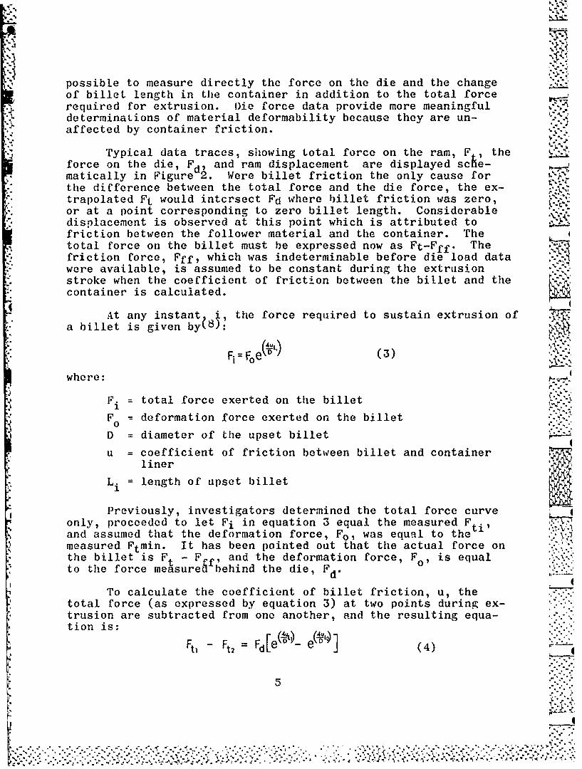
possible to measure directly the force on the die and the changeof billet length in the container in addition to the total forcerequired for extrusion. Oie force data provide more meaningfuldeterminations of material deformability because they are un-affected by container friction.
Typical data traces, showing total force on the ram, F , theforce on the die, Fd, and ram displacement are displayed sche-matically in Figure 2. Were billet friction the only cause forthe difference between the total force and the die force, the ex-trapolated Ft would intcrsect Fd where billet friction was zero,or at a point corresponding to zero billet length. Considerabledisplacement is observed at this point which is attributed tofriction between the follower material and the container. Thetotal force on the billet must be expressed now as Ft-Fff. Thefriction force, Fff, which was indeterminable before die load datawere available, is assumed to be constant during the extrusionstroke when the coefficient of friction between the billet and thecontainer is calculated.
At any instant i, the force required to sustain extrusion ofa billet is given by( 8):
1 eL '-.Fi = Fe\D/ ( 3), ,.-.'
where:
F. = total force exerted on the billet X..-
F° = deformation force exerted on the billet
D = diameter of the upset billet __-
u = coefficient of friction between billet and containerliner
L. length of upset billet
Previously, investigators determined the total force curveonly, proceeded to let Fi in equation 3 equal the measured Fti,and assumed that the deformation force, Fo, was equal to themeasured Ftmin. It has been pointed out that the actual force onthe billet is F - F., and the deformation force, Fo, is equalto the force measuregfbehind the die, Fd.
To calculate the coefficient of billet friction, u, thetotal force (as expressed by equation 3) at two points during ex-trusion are subtracted from one another, and the resulting equa-tion is:
Ftl -Ft, = Fd[e' 07- e(DJ (4)
5 '..::.:
... ... ... ... ... ... ... ... ... ... ... .. . . .'.

Io
The coefficient, u, can be calculated from this expression.Inasmuch as u is influenced by departure of the billet from ideal-ly plastic behavior, billet temperature, and the effect of the com-position of the layer between billet and container liner, thevalues of u should be considered "effective" coefficients of fric-tion.IV. EXPERIMENTAL PROCEDURE
The details of the basic extrusion process and general AFML practices relating to subsequent metalworking operations used inthis investigation have been described in ASD-TDR-62-670. Equip-ment added or modified and any procedural changes made during thecontractual period are discussed in the following section.
A. Extrusion
A Minneapolis-Honeywell Model 1508 Visicorder(Figure 3) was installed at the extrusion press in placeof the 906B model, a smaller and somewhat less versatileinstrument. The new recorder uses a wider chart andpresently employs nine active data channels, although upto 24 channels are available if desired. The nine chan-nels provide data on ram load, die load, ram position,ram speed, extrusion temperature, and the load on eachof the four tie rods. Tie rod tension is recorded dur-ing extrusion as a means of measuring the uniformity ofloading and to detect if the bolster becomes misaligned.
Ram load is measured with a pressure transducerattached to the hydraulic system. Ram speed is measuredby a tachometer coupled to a drum which is rotated by acable fastened to the ram. The cable is under springtension to eliminate slippage and backlash. A 10-turnvariable potentiometer is attached to the drum shaftopposite the tachometer and produces a voltage whichvaries linearly with the ram position.
The die load measurements are obtained from a loadcell positioned directly behind the die by modified back-up tooling, shown in Figure 4. This modification doesnot significantly alter the extrusion procedure, althoughstrain gages must be protected from overheating and cali-bration of the load cell must be checked occasionally toinsure that false readings are not obtained because ofplastic deformation of the cell under high die loadings. 0-:"
The first set of tooling for die force measurementswas designed to accommodate a nominal 1.25-inch diameter(6:1) extrusion. A .125-inch clearance was considered
6
e 41 e k

adequate to minimize the possibility of interference betweenthe extrusion and the load cell due to nose bursts or otherextrusion deformities. This required a 1.5-inch bore in theload cell, placing it somewhat at a disadvantage with respectto cross-section. The stem of the press will withstand atleast 700 tons without plastic deformation, but to allow pas-sage of the extrusion, the load cell cross-section is reducednearly 25 percent and the maximum load to about 530 tons.Increasing the bore diameter to accommodate larger extrusionsfurther reduces allowable tonnage. The calibration step,where a room temperature steel billet is pressed against adie and the stem and die loads are matched against a hydrau-lic gage, endangers the load cell because the full presstonnage is transmitted directly and can be reached veryquickly. Fortunately, in practice, die loads have not ex-ceeded 400 tons even though stem loading is considerablyhigher because of container friction.
An instrument for sensing the temperature of the emergingextrusion was purchased and is being tested, The device wasmanufactured by R{adiation Electronics Company and is soldunder the tradename "Thermodot". It focuses infrared energyemitted by an object onto a lead sulphide detector whichgenerates a signal that is amplified and recorded on the Visi-corder. The backup tooling was modified to allow sensing ofthe extrusion temperature, and both the die load and tempera-ture of the extrusion can be measured simultaneously.
B. F~orging
The inert atmosphere forging chamber was removed from theforge press. Mechanical difficulties and operational encum-berances were such that neither time nor funds would allowthe experimentation and modification considered necessary forthe chamber to be operated effectively. Difficulties includedfracture of the A-inch clear plastic chamber top by a combina-tion of tightly-fitting seals and minor die misalignment. Thecracked too was patched and the o-ring seal around the die wasreplaced by plastic bellows.
A large quantity of argon was required to effect an ade-quate exchange of atmosphere inside the chamber and a steadyflow of argon was required to maintain sufficient positivepressure to preclude entry of air during forging. Fluctua-ting argon temperatures and changes in chamber volume accom-Panying press movement made it difficult to insure adequatepositive pressure of argon. A small quantity of air in thechamber would result in oxidation of the tungsten susceptorand the hot specimens, and the reliability of optical tem-perature control would be reduced by the fumes.
7
-' ~; *~*' A*'.m *

The induction furnace would heat tungsten and molyb-denum specimens to 3200°F without difficulty, and speci-mens could be forged without surface discoloration when c.'.
the chamber was adequately purged. No suitable means wasfound to slowly cool samples of alloys sensitive to ther- -
mal shock.
Since relatively few tungsten or molybdenum basesamples comprised a single forging experiment, argonconsumption on a per-sample basis was very high. Also,surface condition and as-forged dimensions as influencedby oxidation were secondary to alloy deformability andinternal soundness. The latter characteristics can bedetermined readily by heating in an argon atmosphere re-sistance furnace and forging in air.
The Minneapolis Honeywell Model 906B Visicorder,which was used to measure extrusion variables prior toits replacement by the 1508 model, was moved to theforge press so that pressing speed, ram displacement,and deformation pressure can be recorded.
C. Swaging
A Fenn Model 6F, 2-die rotary swaging machine(Figure 5) was purchased during the contractual period.Swaging dies from 1.188 to .375-inch diameter are in useat this time.
V. DISCUSSION AND ROSULTS, BASIC EXTRUSION STUDY
A. W+0.6Cb Billets
Ten billets of W+O.6Cb alloy were requisitioned tofulfill the requirements of the basic extrusion study.Eight billets were ordered from the Wah Chang Corpora-
* tion and two billets were obtained from the Oregon Metal-lurgical Corooration to provide an opportunity to comparebillets provided by these two suppliers to the materialproduced at AFML and Universal Cyclops which was extrudedpreviously.
The seven billets received from the two suppliersranged from 2.941 to 2.950 inches in diameter, 4.313 to4.750 inches in length, and between 20.3 and 22.3 pounds.A -inch x 450 chamfer was machined into the top (lead)end of each billet to aid in the initiation of extrusionand to minimize die damage. Billet hardness averaged65 Rockwell A. The suppliers' ultrasonic and zyglo
8
• . .. ... ... .o....., -... ...... . .... -...... •,... . ,.. . . .., -,.* -.. *. •. . .. ., .. . . .'., ., , . .. . ..-d . .",.- ,. . . . . ., ". , .; ,. .' ", * '/ , . < .. "

examinations indicated that all billets were sound andvisual examination of billet surfaces did not discloseany other defects. A comparison of billet structurecould not be made because the five Wah Chang billetshad been extruded before it was learned that the orderwas not to be completed, and no Wah Chang material wassectioned for macro-examination. One of the Oremet bil-lets was cut longitudinally and the macrostructure isshown in Figure 6 with a macrosection of a W+O.6Cb ingotproduced at AFML shown for comparison.
The analytical data for the W+O.6Cb billets areshown in Table 1. These data indicate that the W+O.6Cbbillets sunplied by Wah Chang and Oremet are very simi-lar in chemistry to the majority of other W+O.6Cbbillets extruded at the AFML facility, however, three ofthe billets supplied by Wah Chang contained roughly twiceas much columbium as the other billets.
B. Extrusion of the W+0.6Cb Alloy
* The six W+O.6Cb billets extruded as part of thisprogram were coated with Corning #7900 glass, heated toeither 3800 or 40000 F, and extruded using ratios between4.3:1 and 7.3:1. All the billets w3re successfully ex-
* .. truded and the data are summarized in Table 2. The Wah.Chang billets used to produce extrusions 994, 995, and
996 contained more columbium than the rest, as mentioned -1in the previous paragraph, but doubling the columbiumcontent at these concentrations apparently has little -<
effect on extrudability.
A number of other W+0.6Cb billets were extruded atAFML and comparisons of material characteristics may bedrawn by examining data from billets produced by Univer-sal Cyclops for Part I of this investigation, and frommaterial produced i the AFML arc furnace for a separatearc melting study(3). Extrusion data for these billetsare listed in Table 2 and comparative analytical data
*_ are shown in Tables 1 and 3.
Figures 7 and 8 show the K factor values obtainedfrom the W+O.6Cb billets listed in Table 2. Considerabledata scatter (the causes of which were discussed in Sec- .tion III) is evident; and, for this reason, a K factor
* band is shown instead of a line.
Several total stem load and die load traces areshown in Figure 9. Only total load traces are available WINfor extrusions 992, 993, and 994, but both total load anddie load curves are shown for extrusions 995, 996, 997
9
0 0
\- * ".. .*%

and 1050. Traces have been superimposed for ease of comparison.
The total load decreases in each case after the billet be-
gins to extrude because of decreasing frictional effect as billet
length decreases, although the load always increases again afterextrusion is more than 60 percent complete because of billet heat
loss and the diminishing effectiveness of the high temperature
lubricant. This increase is not reflected as sharply at the die.
The degree or effect of material heating during deformation inthe die is not known.
In Figure 9 it will be observed that total load for extru-sion 1050 decreases while die load increases. Since all billetswere coated with Corning 7900 glass except for the one from which
extrusion 1050 was produced, the increasing die load in this
instance is believed to result from greater billet heat loss dueto the absence of the glass coating. This provides an indication
of the insulating properties of the coating.
The die load data obtained on the four W+0.6Cb alloy billets Lextruded during this program are shown below. The'die K factor
figures were obtained by inserting the maximum (breakthrough)tonnage values on the die into the equatio . Corresponding stem
load data were extracted from Table 2 for comparison.
STEM DATA DIE DATA L
Extrusion Temp Max Min K Max Min KNumber (Sf) Ratio Tons Tons (psi) Tons Tons (psi)
995 (WC) 3800 6.6:1 450 410 64,300 370 360 53,000
996 (WC) 4000 6.4:1 500 430 72,500 360 335 52,200
997 (OM) 3800 6.5:1 560 480 80,800 340 305 49,100
1050 (UC) 3800 6.2:1 500 460 74,000 390 370 56,400
The K factor values obtained at the die were plotted in
Figure 9 on the same scale used for plotting K factors in Figures7 and 8. While the conclusions that might be drawn are limitedbecause die load data were obtained on only four billets, theabove tabulation indicates that little correlation exists between
the K factor measured at the stem and the one measured at the die.Based on total load measurements, the Oremet billet was the mostdifficult to extrude, followed in order by extrusion 1050, 996, and995. Die load measurements indicate that the Oremet billet was theleast difficult to deform, followed in increasing order by extru-sions 996, 995, and 1050. As discussed in Section III, the diemeasurements are considered a more reliable indicator of billet Ilk,deformability.
10
I0 'I
N N'gek,

The frictional force on the follower material has alreadyb'een discussed (see Section III) and tends to increase the stemload above the load required to actually deform the material.During extrusion of the Oremet billet, it was noticed that a por-tion of the zirconia pedestal block, upon which the billet restsduring heating, had adhered to the base of the billet. In addi-tion to the force required to extrude the alloy, considerableforce was needed to overcome friction between the abrasive zirconiaand the container liner. This condition contributed to the highstem load recorded for this extrusion.
If the die K factors plotted in Figure 9 present an accurateindication of the effect of temperature on deformability, the slopeof the line shows that changing billet temperature has a less pro-nounced effect on die K factor than on the stem extrusion constant.The degree of data scatter at the die is not evident, consideringthe conditions of extrusion and the number of measurements.
The coefficient of friction between the bill et and the con-tainer was calculated by use of equation 4 Page 5). The resultsof these calculations are as follows:
Extrusion Coefficient ofNumber Billet Friction
995 0.050
996 0. 070
997 0.085 " v1050 0.045
aAnalytical data in Tables 1 and 3 indicate that the W+0.6Cb
billets supolied by Wah Chang contained a higher interstitial andresidual metallic impurity level than billets supplied by UniversalCyclops and AFML. However, the results of deforming operations are
* not in agreement with the apparent differences in purity levels._* The extrusion data show that the Wah Chang material was more easily
extruded and photomicrographs (Figures 10 and 11) show that thealloy showed a stronger tendency to recrystallize during the pro-.cess, both signs suggesting a higher purity material. This ten-dency also was noted when extruding a W+0.6Cb billet produced inthe AFML furnace from Wah Chang electrodes (Ingot VA-86, Extrusion -956).
The apparent lack of correlation between billet chemistry andextrudability does not indicate analytical error, but rather itreflects a difference in analytical and reporting techniques, witha predominance of higher "less than" values reported by Wah Chang
.I*N

implying higher impurity levels. Ingot VA-86 was produced in theAFML furnace from the same electrode lot utilized by Wah Chang for '._-
their ingots. The analysis of this ingot by Le Doux, Inc., shownin Table 3, indicates very little difference in chemistry existsbetween this and other ingots shown in the table except for carbonand oxygen. While the "less than" values reported by Wah Changare undoubtedly correct, the actual values appear considerablylower than many of those indicated. Differences in extrudabilityand other properties may be related to electrode suppliers as wellas to differences in arc melting technique.
Data have been extracted from Tables 1, 2, and 3 and arrangedto show the relation of carbon content to K factor. All of thebillets listed below were heated to 3800OF for extrusion.
BilletExtrusion No. & Electrode Extrusion Reported K FactorNumber Source Source Ratio ppm C (psi)
752 KCI138A(UC) GE 4.1:1 44 80,500
753 KC11388(UC) GE 7.6:1 44 82,500
755 KClI46A(UC) Sy 4 .4 :1(b) 45 87,500
756 KC1I46B(UC) Sy 5 .5 :I() 45 84,400
757 KC1137A(UC) GE 6 .7 :i(b) 27 87,400
762 KC1145B(UC) Sy 4.2:1 50 90,800
1050 KCII48B(UC) Sy 6 .2 :1 (c) 43 74,000
*896 VA-68(AFML) GE 6.3:1 44 Stuck
935 VA-78(AFML) GE 6.4:1 10 75,000
936 VA-79(AFML) GE 8.4:1 18 75,000
948 VA-83U(AFML) GE 6.4:1 123 Stuck
951 VA-83L(AFML) GE 3.0:1 123 Stuck~d"
956 VA-86(AFML) WC 6.4:1 6 72,700
957 VA-87(AFML) W 6.4:1 51 Stuck
958 VA-88(AFML) GE 6.4:1 230 Stuck
966 VA-91(AFML) GE 6.4:1 230 Stuck
974 VA-92(APNL) W 6.3:1 25 83,800
992 31015T(WC) WC 4.3:1 30 76,000
995 31192B(WC) WC 6.6:1 30 64,300 ?,*.
12-"

(a) Sources: UC - Universal Cyclops, GE - General Electric,Sy - Sylvania, AFML - Air Force MaterialsLaboratory, W - Westinghouse, WC - Wah Chang
(b) Rectangular Die
(c) No glass lubricant(d) Billet heated to 4200°F"
More data on the effect of carbon can be determined byconverting 4000°F K factor data to 3800OF data. This was doneby adding 6,000 psi to the 4000OF K factor values, which wouldbe the expected increase according to the slope of the K fac-tor band.
Billet ConvertedExtr. No. & Electrode Extr. Reported K FactorNo. Source Source Ratio ppm C (psi)
632 KC1072(UC) Sy 4.4:1 21 95,400
746 KCII43A(UC) Sy 4.0:1 20 80,700
- 747 KCII43B(UC) Sy 7.9:1 20 82,000
758 KCl147A(UC) GE 4 .5:1(b) 60 77,800
759 KCIl47B(UC) GE 7 .0 :1 (b) 60 88,000
763 KCl145A(UC) Sy 4.1:1 50 79,400
(Notes of previous tabulation apply)
The addition of carbon alone to the W+0.6Cb alloy could -.7
" be beneficial if increases in elevated temperature strengthcan be obtained while still having an extrudable alloy. A"go - no go" diagram is shown in Figure 12, where successfuland unsuccessful extrusions are plotted according to carbon
content and extrusion ratio. It appears that 40 to 60 ppmcarbon is the critical range where the W+0.6Cb alloy becomesso resistant to deformation that it cannot be extruded bypresent Air Force Materials Laboratory extrusion techniquesand equipment.
C. Evaluation of W+0.6Cb Extrusions
The surface condition of extrusions were rated accordingto the examples shown in Figure 13. Surface condition was
*O determined after oxide, glass lubricant and adhering Sil-0-Cel had been sandblasted away. The surfaces of the W+0.6Cbextrusions were generally good, regardless of the supplier.Defects that did exist were of such a nature that frequentlyone was able to identify the source of the billet from thenature of the extrusion surface. An ingot melted in the AFML
'1LO -::=.:

furnace from Wah Chang electrodes produced an extrusion surfacesimilar to that found on extrusions produced from material meltedby Wah Chang. AFML and Universal Cyclops ingots melted from GeneralElectric electrodes produced extrusions which had similar surfaces.Examples of extrusion surfaces are shown in Figure 14.
Except for obvious laps, seams, and fissures, little could besaid about the exterior layer of the extruded material. It wasfound that many defects were hidden by smeared metal and were notdetected until sampleswere severely etched or subjected to defor-mation perpendicular to extrusion direction. Machining 60 to 100mils from the surface removes all but the most serious defects. It 61-is believed that greater material recovery could be obtained by im-proving billet machining methods to avoid generating minor surfacecracks that tend to propagate during billet extrusion. The surfaceof extrusion 1050, which was produced from an uncoated billet, was 4.found to be at least as good as if not better than the surfaces ofextrusions produced from glass-coated billets.
The dimensions of the W+O.6Cb extrusions generally increased -from nose to tail because of die wear. Dimersional variation, ininches, of extrusions produced from Wah Chang billets and fromseveral Universal Cyclops billets are shown below.
Ext. TSmO.No. F Nose Center Tail
992 (WC) 3800 1.482 1.483 1.483
993 (WC) 4000 1.482 1.479 1.482
994 (WC) 4000 1.135 1.130 1.140
995 (WC) 3800 1.193 1.197 1.208
996 (WC) 4000 1.215 1.210 1.214
752 (UC) 3800 1.518 1.520 1.523
753 (UC) 3800 1.116 1.118 1.120
743 (UC) 4000 1.225 1.228 1.230
744 (UC) 4000 1.141 1.144 1.156935 (AFML) 3800 1.203 1.208 1.208
936 (AFML) 3800 1.063 1.065 1.074956 (AFML) 3800 1.214 1.215 1.216
From the data it is apparent that the effect of the W+0.6Cballoy on the dies is about the same, re'gardless of billet source.
Extrusions were sampled according to the diagram in Figure '.15 unless special sampling was required for a separate study.
14
*V- 51t

Nose, center, and tail samples of W+0.6Cb extrusions producedfrom billets supplied by feir different arc melting facilitiesare shown in Figure 16. Thiese structures resulted from ex-truding at 3800F through round dies giving approximately a6.5:1 reduction ratio. In all cases the center sample showsmore recrystallization than either the nose or tail samples.This observation is supported by the hardness data which ispresented in Table 4. The nose and tail sections were harderthan the center section. The structure contained in the cen-ter sample is considered representative of that contained inabout 75 percent of the bar. The nose region of the bar suffersheat loss during transfer and from contact with the relatively-.cold nose plug in addition to being subjected to less deforma-tion. The tail region suffers qreater heat loss because ofthe length of time for contact with the cold container and theproximity of the graphite follower block which is normally atroom temperature when nlaced in the container.
D. 92W+6Mo+2Cb Billets
Thirty billets of the 92-6-2 composition were to be ob-tained from two outside suppliers, so Oremet and Wah Changwere contacted and 1 equested to quote on 15 billets each. .Because of the tendency of arc melted ingots of this alloy tocrack, both of the mentioned suppliers declined to quote onthis order and it was necessary to produce all of the ingotsin the AFML furnace.
Electrode material for these ingots was obtained from theGeneral Electric Corporation as 1 -inch diameter, hydrostatical-ly pressed and hydrogen sintered bars of a 94 percent tungsten +6 percent molybdenum mixture. Each electrode contained a 3/8-inch bore through which wires of columbium were inserted toprovide the 2 percent addition. All electrodes were joined ,'-mechanically with a 1-8NC thread. The characteristics of thematerial, as provided by the supplier, are shown in Table 5.
The ingots were produced without difficulty using para-meters similar to those developed during the investigation ofarc melting this alloy(5 ). A typical melting record for theproduction of 33-inch ingots is shown in Table 6. The meltingcurrent was increased slightly, from 5500 to 5800 amperes, inan effort to obtain better in:rot surfaces. An arc cast ingotand a machined billet are shown in Figure 17 and the ingot macro-structure is displayed in Figure 18. The ingot grain size isconsiderably finer than the grain size of the W+0.6Cb ingotsshown in Figure 4, a result of the 6 percent molybdenumaddition and the increased columbium content. Some ingotmicrostructures are shown in Figure 19. These structures aretypical of tungsten base alloys and do not show any second
15'
:,. - ,
:: ::::::::::::::: ::::: ::::::::::::::::::::::::::::::::::::::::::::::::::.:.::.:•:: ===== =========================1 =====

phase at the grain boundaries although a fairly large numberof voids are evident at low magnification, where inclusionswere removed during electropolishing and etching.
Although all billets were machined to a nominal 2.940-inch diameter, lengths ranged between 3.5 to 6.6 inches, andfacilities were available at AFMLfor detection of internal
billet flaws, so as an alternate, visual inspection was usedto detect flaws that extended to the billet surface. Billethardness data are shown in Table 7 and billet analyses areshown in Table 8.
E. Extrusion and Evaluation of the 92W+6Mo+2Cb Alloy
Extrusion data for 92-6-2 billets are summarized in Table9. Generally the pressure required to extrude the 92-6-2billets exceeded that needed to extrude the W+0.6Cb alloy atthe same temDeratures and reductions. Scatter in K factorvalues was even greater at elevated temperatures (Figure 20)than that observed for the W+0.6Cb alloy.
A major problem with the 92-6-2 alloy has been the condi-tion of the as-extruded surface, which was usually rated fromfair to poor. Some surface flaws extended deep enough to pre-clude any possibility of obtaining material for subsequentworkability operations. Examples of 92-6-2 extrusions origina-ting from 3i-inch ingots are shown in Figure 21. Also, a num- 6ber of extrusions contained internal cracks similar to those .shown in Figure 22. Cracks which appear to follow extrusionflow lines and which show crumbling or other evidence ofrelative motion at the interface were apparently present inthe billet prior to extrusion. While cracks may have occurredduring heating to extrusion temperature or during billet upset ain the container, it is most likely that they were present inthe ingot prior to billet machining. Additional precautionswere taken to avoid thermal shock during cooling of the ingot
, in the furnace after melting was completed. Throttling the:" mold cooling water to a trickle soon after melting was corn-
pleted is believed to have contributed significantly towardeliminating this problem. Cracks of a different type werepresent in other 92-6-2 extrusions which did not follow flowlines and were quite fine, showing no crumbling along theedges. These cracks are believed to have occurred after ex-trusion was como)leted, although no direct evidence is availableto support this conclusion. S
Extrusion surface defects were believed to be a function ." ).4of ingot surface and/or arc melting practice, where ingotdefects extended deep enough below the surface to precludetheir complete removal by machining to billet diameter. It
7-1
16 -
"' ' ' "' .' L'- ""' ''" ° " . -' ', , -'-A . " " . " , - .,' . -. " " "- - ." - ~ , . ' .
,': -.-- i: ., \ ! ! . " _ ___ -L. :::K: .'-' .' .- ; '..-, ... ",

was thought that a 4-inch ingot would be of sufficient diameterto contain surface defects in the layer removed by machining, sothe arc furnace water jacket was modified to accommodate 4-inchmolds and the balance of the 92-6-2 ingots (beginning with VA-94)was made in the larger molds. Electrodes measuring 1-3/4 inchesin diameter were ordered for these ingots and the characteristicsof this material are shown in Table 5. More melting current wasrequired to obtain a smooth surface on a 4-inch ingot, and 6300to 6500 amperes was used instead of the 5500 to 5800 amperes whichseemed satisfactory for the 3!h-inch ingots. A representativemelting record for the production of 4-inch ingots is shown inTable 10.
Changing to the 4-inch diameter ingot resulted in more materiallosses by machining without significantly improving extrusion sur-faces. Examples of extrusion produced from 4-inch ingots are shownin Figure 20. All extrusions after 943 (Table 9) were made frombillets originating from 4-inch ingots.
The 92-6-2 alloy is more sensitive to failure from thermalstresses than is the W+0.6Cb alloy. It was found in several in-stances during the investigation of W+0.6Cb, that extrusions whichdid not clear the die and were subjected to rapid cooling in therunout tube were still sound and suitable for workability evaluation.The original 88-6-6 alloy could not be obtained as sound ingotsbecause stresses developing during cooling would cause severe crack-ing, and reducing the columbium content from six to two percenthas not completely overcome this problem.
As was the case with the W+0.6Cb extrusions, the dimensionsof the 92-6-2 alloy bars increased from nose to tail due to diewear. Dimensions, in inches, of several 92-6-2 extrusions areas follows:
Extr. Extrusion "No. Temp., oF Nose Center Tail
911 3800 1.484 1.485 1.492 -.912 4000 1.481 1.491 1.494913 4000 1.223 1.223 1.230914 4200 1.493 1.502 1.520915 4200 1.150 1.154 1.162926 4000 1.473 1.475 1.493927 4000 1.490 1.491 1.502928 4000 1.494 1.494 1.496943 4000 1.499 1.503 1.517
1008 3800 1.484 1.488 1.4881009 4000 1.505 1.505 1.510
17
•~ ~ ~ ~ ~ ~ ~ ~ ~ ~ ~ ~~~~1%" . -- - .- ,' .' .r-' ": ,",''-'2-..

It is difficult to relate directly the die wear caused byextrusion of the 92-6-2 alloy to that measured during extrusionof W+0.6Cb because the above tabulation contains a predominanceof 4:1 extrusions while similar data for W+0.6Cb reported pre-viously shows a predominance of 6:1 extrusions. Consideringthat 4:1 extrusions require less pressure and the distance betweennose and tail measurements is about 2/3 that of 6:1 extrusions,the 92-6-2 alloy causes considerably more die wear than a super-ficil comparison of data indicates. It is not certain whetherthe effect on dies is simply a function of the 92-6-2 alloy'sincreased resistance to deformation or whether it is related tothe poor surfaces of the 92-6-2 extrusions.
The flame-sprayed zirconia coating applied to steel dies isbelieved to be a most significant development contributing toward '.
successful high temperature extrusions; however, variation in diedesign as it might further improve the process has received scantattention. Figure 24 shows the die designs used during this in-vestigation. The dimensions to which the dies are machined areshown, and the indicated ratios are obtained after application ofa 30-mil coating of zirconia. Unserviceable dies can be reclaimedby removing all of the old coating and applying a new layer.
An effort to improve die lubrication involved the addition ofmolybdenum disulphide to the zirconia during the flame sprayingstep. The coating spalled from the die during a trial steel ex-trusion, indicating that the MoS2 interfered with the adherenceof the ZrO2. No 92-6-2 extrusions were attempted with this typeof die.
The effect of extruding through rectangular dies is not ob-literated by data scatter and Figures 7 and 20 clearly indicatethat more pressure is required to produce rectangular cross-sections. The effects of non-uniform deformation, greater diesurface, and variable entry angle are significant but difficultto isolate for separate study. Three round extrusions were madeusing dies with entry cones greater or less than 90 degrees, butextrudability differences were not great enough to be indicatedby K factor data, and this study was abandoned because die loadtooling was not available until near the end of the investigationand no billets were available for this determination. It isinteresting; to note that the 600 die did not increase the pressurerequired to produce lf+O.(iCb extrusion 742 although it was expectedthat die friction would increase appreciably as die entry anglewas decreased to this value. No difficulties or advantages werenoted when producing W+O.GCb extrusion 744 with a 100 degree dieor 92-6-2 extrusion with a 120 degree die.
Hardness data from several 92-6-2 extrusions are shown in
Table 11. Hardness variation across the section and along thelength of the extrusion was not significant. Although the 92-6-2
18r6
k-, 77.-

alloy shows ample evidence of being more resistant to deformationthan the W+0.6Cb alloy over a wide rangle of temperatures, roomtemperature hardness data indicates that it has less resistanceto hardness indenter penetration.
Specimens were cut from several extrusions Cor machininginto tensile specimens (see Figure 25). The specimens shown inFigure 26 contained a fairly large amount of recrystallizationwhich accounts for the relatively low values obtained at 3000OFin vacuum. These data are shown in Table 12.
Extrusions 941 and 942 were produced using graphite nose andfollower blocks heated to 2800°F instead of the usual 1600OF steelnose plug and the room temperature follower block. This was doneto reduce the breakthrough tonnage by decreasing the amount ofbillet heat lost to the nose plug, and to reduce the force re-quired to push the tail of the extrusion through the die becauseof heat lost to the cold follower block. Stem load traces indi-cated that the shape of the extrusion curve was not changedappreciably, in fact the breakthrough tonnages were higher thannormal. No additional work was done with heated graphite noseand follower blocks.
In an attempt to overcome the difficulty with poor extrusionsurfaces, and to experiment with a substitute for glass aa a lubri-cant, some of the 92-6-2 billets were machined to a smaller diameterto enable their use with copper, steel, and molybdenum jackets. Onebillet was extruded using a copper jacket and two each were extrudedwith steel and molybdenum jackets. The copper and steel cans werepainted with 9776 glass on the inside, inserted into the container,and allowed to reach container temperature (8000F). The copperjacket was used with extrusion 1042 and it did not affect the Kfactor nor i,,iprove the extrusion surface. Judging from the copperin the runout tube, this jacket melted quickly and squirted fromthe die under high pressure. The steel jackets used with extru-sions 1045 and 1047 lowered the K factor somewhat (although thismay have been a function of reduced billet diameter) but the sur-face of the extrusions were very poor.
The molybdenum jackets had a high enough melting point topermit being heated with the billet. Although these billets wereextruded without any glass coating, the K factor values were verylow (Figure 20). vie same die was used for both extrusions andwas in excellent condition afterwards. Some pressure reductionwas undoubtedly due to the reduction in billet diameter requiredfor accommodation of a 1/8-inch jacket. A number of bulges andcracks in the jacketed extrusion indicated that a poor surfacewas underneath, and removal of the jacket confirmed this observa- Ition.
19
4 1,j
IS* * A A~ ',- , .N' *

The 92-6-2 alloy did not recrystallize as readily asthe W+O.6Cb alloy. The microstructures of several extrusionsare shown in Figures 27 and 28. The structures in Figure 28were photographed at lower magnification to show that alter-nate bands of wrought and recrystallized structure are present.It was noticed during preoaration of samples that some relief,or unevenness of surface, was oresent after electropolishingand etching. These ridges were believed to result from seg- -'-.
re-ation, and the areas of varying composition were elongatedduring the extrusion nrocess. These re-ions reacted at dif-ferent rates when subjected to polishing and etching. Thiscondition also favors bands of recrystallized and wroughtstructure. To avoid this inhomogeneity, better arc meltingpractices must be established and long time, high temneratureheat treatments of these ingots should be investigated.
F. Lubrication 10valuation
While nearly all of the refractory alloy billets extrudedup to this time have been coated with a glass that has the de-
*sired viscosity at billet temperature, it appears that theactual lubrication value of the glass is not significant underthe conditions of extrusion in the high temperature range usedfor tungsten base alloys. Except for the possible benefitsthe coating affords in retarding oxidation losses and lessen- .ing billet heat dissipation, the use of glass often may bedeterimental to the extrusion process.
The choice of a glass composition for application to abillet has depended entirely on the temperature to which thebillet will be heated for extrusion. Since glass viscosityis temperature-denendent, a composition with too low a soften-ing temperature will flow to the base of the billet duringheating. This will cause the billet to stick to the zirconiapedestal block so that both the block and the thermocouple maybe destroyed when the billet is removed. Also, the apparentincrease in billet diameter at the base caused by an accumu-lation of displaced glass makes it difficult to manually insert
* athe billet into the container.
To compensate for the thickness of the 30-mil coatingnormally applied, billets are machined to a smaller diameterthan would be necessary if a coating were not used. Beforethe billet begins to extrude, it is upset to container diameterby ram pressure. In the initial stage of upset, the billetbulges in the center until it contacts the container, and asthe billet approaches container diameter, the lubricant isprogressively squeezed toward the ends. The glass forced tothe rear of the biLlet is removed from the region wherelubrication is needed and it may even increase frictional
20
..................... .. ..- ...............-'....-........ .: .d.-

r.°
effects when it becomes mixed with the graphite followerblock and is chilled. The material machined from the billet idiameter to compensate for glass coating thickness permitsa large amount of deformation as the glass is squeezed fromthe center, a condition likely to initiate failure inside thebillet and/or cause propagation of minor flaws in tile billetsurface.
Inasmuch as certain glasses require high temperaturesbefore they become fluid enough to lubricate, it follows thatthey must be maintained at high temperatures Jluring the extru-sion process to function as lubricants. The container of theextrusion press is limited to a temperature range of 900 to1O0000F by the nature of the heating elements and the propertiesof the steel. The high temperature glasses are rigid andabrasive at this temperature. The higher the softening tem-perature of the glass, the thicker will be the non-lubricatinglayer between billet and container. A glass that is liquidat container temperature but viscous enough at extrusion tem-perature to preclude running off the billet would be idealfor this process but is not available.
Some of the K factor data scatter reported in this in-vestigation is believed to result from various effects causedby the use of high temperature glass. No ingots of 92-6-2were extruded without a glass coating, but the W+0.6Cb billetused to produce extrusion 1050 (see Table 2 and Figure 7) washeated to 3800OF and extruded without applied lubrication. Anoxide coating formed, however, during the heating process. -'Ext-asion pressure was so low in this instance that extrusionof "bare" billets is worthy of further investigation. Whilethe value of glass as a lubricant is doubtful under the con-ditions required for the extrusion of tungsten base alloys,the application of glass to the 92-6-2 billets is not relatedto the poor surfaces of the extrusions. The same lubricationtechniques did not adversely affect the extrusion surfacesofW+).6Cb or other tungsten base alloys. The employment of
copper, steel, and molybdenum cans, while reducing the effort '.44I
required for extrusion, (lid not improve surfaces and in some .P-4cases affected the surfaces adversely. It appears that poorsurfaces on 92-6-2 extrusions were more a function of thenature of the alloy and less a function of extrusion practice.
As mentioned previously, the use of copper and steel canswith the 92-6-2 alloy did not produce any significant improve- _ment, but molybdenum jackets materially reduced extrusion pres- ,sure. Futur.e studies should investigate plasma-sprayed coat-ings of pure nolybdenum 30 to 60 mils thick to compare thesuitability of this technique to the successful but expensivemethod of applying molybdenum cans.
21
V ,%r %-
-....-.-.:.'-: , -" -.*- ,,'-. .,,,-* .... ,., .. - --: -..,,.-,- -.-.*,',-:-- . ...- :, . .,.*, ,: ...

VI. THERMAL-MECHANICAL EFFECTS ---.
A. Forging
To obtain preliminary forging data on the W+0.6Cballoy, portions of extrusions 750 and 752 were selectedfor study. This material was extruded through 4:1 diesat 3200 and 38000 F, respectively. Portions of the 1!2-inch rounds were painted with Corning 7052 glass, heatedto 27000 F, and "side forged" to blanks measuring 4 x 2V2x N inches. These blanks were cut into smaller samplesmeasuring approximately 1 x 1 x N inches and annealedfor one hour at 3400OF to insure complete recrystalliza-tion. Annealing conditions were based on the data con-tained in Table 13 which show the recrystallization be-havior of W+0.6Cb in the as-extruded condition. Thestructures after recrystallization were essentially iden-tical in spite of the difference in extrusion temperature.
No data were available on forging the W+0.6Cb alloyat temperatures below 16000 F, so samples from each extru-sion were heated to 1000, 1200, 1400, and 1600OF and re-duced 75% by forging. These samples were not glasscoated prior to heating and specimen oxidation was foundto be minimal at these temperatures. All samples forgedin the 1000 to 1600 degree temperature range showed edgecracking, with the severity of cracking decreasing asforging temperature increased, so that only minor flaws .. T
could be observed in the samples forged at the highest V .temperature. The (lies of the forge press were machinedfrom an H-12 tool steel and were heat treated to 49-51 Rc.These dies showed the impression of the 10000F samplesand one die cracked during forging of the 12000' samples.Although one forging die was destroyed, the balance offorging was completed by keeping the samples away fromthe cracked area.
Heat is extracted rapidly from the forging by theforge press and all samples were chilled as a result. __
All specimens forged between 1000 and 1400OF showed alarge number of fine internal cracks when sectioned. Itis not known whether this would have occurred if chillingwere avoided by using heated dies and/or a forge hammer,and samples were cooled slowly to room temnerature afterforging, or whether samples would have cracked at theselow forging temperatures and high reductions regardlessof the precautions.
Reliable hardness data could not be obtained on anyof these samples because the fine network of cracks causedcrumbling around the impression. All hardness readings
22
07. .----.

were in the 55 to 65 R range which were obviously in error. Itappears that obtaining major reductions by forging 1600°F has nopractical value. The low temperature range may be useful for oper-ations involving minor deformation, however, such as straighteningextrusions or rolling samples where it is desired to keep oxidationlosses at a minimum.
Additional pieces of round extrusions were side forged andannealed, as described previously, to obtain samples for determin- 4ing the effects of forging to several reductions at 1600, 2000 and24000 F. Two samples each from extrusions 993, 763, and 761 wereused for this study. These three extrusions were made with 4:1dies. Extrusions 993 and 763 were extruded at 4000OF and 761 wasextruded at 32000 F. While the original extruded structures, shownin Figures 10 and 11, were quite different, the structures after 4side forging at 2700OF and annealing one hour at 3400OF were thesame except that the recrystallized grain size of the 993 sampleswas somewhat larger.
The annealed samples were cut diagonally to produce wedges(Figure 29) and marked along the sloping surface so that percentreduction could be obtained from the original dimensions indicatedby the markings. No glass coatingswere employed on samples duringforging. Reductions from 20 to 80 percent were obtained with onestroke of the press. Some crack indications were present in bothsamples of 761 and one sample of 993. These cracks may have occur-red as a result of cooling too rapidly from the annealing tempera- Ature. These specimens were used for determination of forgeability,effect of reduction on recrystallization behavior, and hardness.All samples survived the forging step without separating, althoughthe original cracks were now more obvious. Edge cracking thatoccurred during the preliminary forging study at 1600OF was notpresent in the region reduced 80 percent in the wedge at this tem- 4perature, and except for the original defects already mentioned,forging at 1600, 2000, and 24000F was satisfactory. Hardness datafrom these samples are shown in Table 14.
The samples were heated for one hour at 3000OF to determinethe effect of forging temperature and reduction on recrystallization.Some of the recrystallized structures are shown in Figure 29. Onlya small amount of wrought structure was detected in the samples, asrecrystallization was essentially complete. Large grains existedin the portion of the sample reduced 20 percent and fine grainswere present in the region of maximum reduction. Although grainsize did not increase uniformly along the samples, the trend ofthe grain size relative to percent reduction was unmistakable.
The 92-6-2 alloy was forged also, but more rectangular extru-sion stock was available and the pre-forging step was not necessary.Samples cut from the as-extruded bar were annealed at several tem-peratures for one hour to determine the effect of annealing on
23
LU N.
*~~~~l )0 X.-*- * * 1- -. -

hardness. Because of the scarcity of sound material, portionsof extrusions 898, 899, and 900 were used for this study, since K-:these data could be obtained on unsound material. The original '.<
struztures are shown in Figure 26, and the effect of recrystal- v-lization temperature on structure is shown in Figure 30. Hard-ness data in Table 15 indicate that the material becomes some-what softer as annealing temperature is increased. Estimatedpercent recrystallization resulting from annealing 1 hour attemperatures between 2600 and 3400 F are shown in Table 16 andsamples for subsequent forging operations were annealed forone hour at 3400°F based on this data.
Preliminary forging studies, using 70% reduction, at 1200,1700, and 22000F indicated that 2200°F was the most favorabletemperature, as other samples contained a large number ofcracks. Samples of 92-6-2 forged at the three temperatures '-
are shown in Figure 31.
The few large samples of rectangular extrusions that weresound enough for cutting into wedges were badly cracked afterannealing and no additional forging studies were done on the92-6-2 alloy.
B. Rolling
Only a small quantity of W+0.6Cb samples was available forrolling after other operations had been completed. Samples ofW+0.6Cb round extrusions 761, 763, 992, and 993 were preparedby forging and annealing in the same manner as used when pre- ,;paring samples for forging. Extrusion 759 was a rectangularextrusion and only the 3400°F recrystallization was needed.Although more care was observed in sample preparation, mostof the pieces broke during early rolling passes. The 1600,2000, and 2400°F temperatures used were less satisfactory forrolling than for forging, although better rolling results wereobtained at the highest temperature. Rolling results are asfollows:
Initial FinalSample Temp., OF Thickness Thickness Remarks
759 1600 .587 --- Cracked on first pass
759 2600 .589 .223 10 passes,minor cracksremoved between passes
759 2400 .587 .125 12 passes,minor cracksremoved between passes
761 2000 .709 .580 split on third pass
763 2000 .741 .680 split on first Pass
763 2400 .742 .625 split on second pass
992 2000 .698 .563 split on third pass
993 2400 .748 .460 split on fourth pass
24
1,2 .t
'W--GIN

Most samples showed signs of failure during the firstrolling pass and where it was practical to do so, defectiveareas were removed before further rolling was attempted. A Acommon cause of failure in the samples forged from rounds endannealed was a tendency of the specimens to split in the cen-ter as it emerged from the rolls, so that two pieces half the 0desired thickness were obtained. Samples of extrusion 759,which was rectangular and required only a one hour anneal at3400°F before rolling, showed a strong tendency toward edgecracking. Rolling was halted occasionally while cracks wereremoved by grinding or by cutting off the affected area. Ex- ,.amples of sample cracking are shown in Figure 32, and available -.hardness data are shown in Table 14.
The canacity of the rolling mill would not permit heavyreductions on initial passes, but a more successful productmight have been obtained if the annealed specimens had been 4-.
forzed 40 percent or more before rolling was attempted. No q. .
material of the 92-6-2 composition was suitable for rolling.
C. Swagirng
Swaging proved to be a use',.l method of reducing extrudedsections of refractory alloys in order to evaluate the effectof a deforming operation on these materials. One is limitedto a fixed set of reductions which are presently determined byavailable die sizes. The largest die will swage a bar to1.188 inches. Subsequent swaging passes utilize 1.062, .937,.843, .750, .687, and .609-inch dies. Several smaller dies(to .375 inch) were not used for tungsten swaging becausestock diameter was not suitable for tensile specimens.
Dies were machined from hot-work die steel (VASCO-M2) andheat treated to 48-52 Rc. The metal working portion of the Mdies measured 1% to 2 times the diameter, which places them inthe "finishing die" rather than the "working die" category, asthey resemble the design commonly used for straightening. Dieblocks were cleaned between passes using a toolmaker's grinderand emery paper to remove adhering tungsten oxide. Inspectionafter cleaning disclosed a number of circumferential cracks inthe working surface of several dies after the first tungstenbar was swaged at 27000 F, however, this condition did notworsen noticeably after additional bars were swaged.
Both the W+0.6Cb alloy and the 92-6-2 alloy were checkedfor cracks prior to swaging by etching the end of the bar witha strong HF-IN03 solution and checking with dye penetrant.When cracks existed they were usually obvious enough afteretching to make confirmation with dye penetrant unneccessary. ___
25
0..
r-

Current swaging practice at the Air Force Materials Laboratoryentails heating the as-extruded bar in a Harrop portable Globar
* furnace or a Pereney Globar furnace and swaging with three to fiveminute reheats between passes. Annealing was done after firstswaging to a diameter from which the .609-inch die will produce the
* desired reduction. Extrusion samples less than 7 inches long aredifficult to handle because the length is insufficient to permitswaging to the center of the bar when the sample is inserted intothe dies from either end. On the other hand, the internal dimen-sions of the two-mentioned furnaces will not allow reheating ofbars more than 17 inches long because the furnace doors cannot be
" closed. The bars must be slowly cooled, cut to shorter lengths,and reheated before swaging can proceed.
Sections of W+O.6Cb extrusions 974, 994, 995 and 997 were usedfor swaging evaluation. Swaging samples were removed from the aboveextrusions according to the diagram on Figure 15. In order to
, evaluate the effect of swaging on the as-extruded surface, the onlypre-swaging preparations made were to sandblast the sample andremove serious defects by cutting off the affected portion of thebar. If surface preparation had been considered necessary, a
. single swaging pass would have been required to straighten the ex-trusions sufficiently to allow machining in a lathe.
Samples from extrusions 974, 995, and 997 were heated 30minutes at 2700oF and swaged from the nominal 1.2-inch extrusiondiameter to .937 inch in two passes. Sample 994 was heated to 2400°Ffor 30 minutes and swaged to .843 inch in three passes. Three tofive minutes were allowed for reheating between each pass, No diffi-culties were encountered in any of these operations, however, it wasnoted that the material heated to 2400OF was more difficult to feedmanually into the dies.
In view of the additional reduction of the as-extruded section,which previously had recrystallized completely after one hour at .3200°F (Table 13), it was assumed that the extruded and swagedmaterial also would recrystallize completely under these conditions.After subjecting specimens 994, 995, and 997 to this annealing treat-nment, it was discovered that the recrystallization was only about 90percent complete. Specimen 974 was annealed at 3400°F for one hourwhich resulted in complete recrystallization and even produced somegrain growth.
Samples 974, 995, and 997 were swaged to .609-inch bar stockat 27000 F, and a sample of 995 was swaged to .609 inch at 24000 F, .which reduced the annealed structure 60 percent in four passes.5Sample 994 was swaged from .843 to .687 at 22000F, a reduction of35 percent. Some microstructures of annealed and swaged samplesare shown in Figure 33.
r 26
'.'. . ..
O J.> ""-

The appearance of the as-swaged surface of the .609-inchstock was superior to that of the original as-extruded samples.This was due in part to the nature of the dies, although most ofthe improvement occurred as a result of oxidation in the furnace:.and during transfer to and from the swaging machine. The vola-tility of the oxide enabled removal of the outer layers of materialcontaining the minor surface defects. :' "
Swaging of W+O.(3Cb bars had been done previously at the _JWestinghouse N terials Manufacturing Division, Blairsville,Pennsylvania(3). These samples were essentially the same sizeas those just described, but the heating to 2800OF was necessarybefore the operator could force the material through the diesmanually. The apparent difference in swageability was a result ofdifferent die designs. The dies used for swaging at Blairsville-. %used a 20 degree entrance angle while the 12 degree entrance angleemployed in the Fenn dies at the Air Force Materials Laboratoryallowed swaging of W+O.6Cb alloy as low as 22000 F.
Two bars of 92-6-2 alloy were found suitable for swaging.Extrusion 1028 was swaged at 2700oF from the original 1.17-inchdiameter to .609 inch without an annealing step., Three-inch see-tions were cut from the rod and two of the four samples showedinternal cracks. One sample was machined into a tensile specimenand the other was annealed one hour at 3400oF before machining intoa specimen. Tensile data on the 92-6-2 alloy are shown in Table12. Extrusion 1043 appeared suitable for swaging and withstoodreduction to .937 inch, a one hour anneal at 34000F, and furtherreduction through the .843-inch die. The bar began to break intoseveral pieces while it was being worked in the .750-inch die andswagi -ig was discontinued. Microstructures of swa-ed 92-6-2 areshowiA in Figure 34.
The results of the high temperature tensile tests of theswaged W+06Cb is shown in Table 17, and test results on othersamples of wrought +0.6Cb alloy are shown for comparison. Thedata in Table 17 indicate that swaging temperature does not >appreciably aft'ect hi-h temperature tensile properties, at leastin the range of swagn- temperatures used. Air Force MaterialsLaboratory personnel9 obtained appreciably higher strength L':values by forging samples between 40 and 54 percent at 26750Fand machining round samples from the center. Of particular sig-nificance is that their samples were maintained at 3000OF for15 minutes before stress was applied, while the sample tested byUnion Carbide(2) was held at temperature for only five minutes.
27

VII. MAXIMUM YIELD EFFORT
A variety of billets have been extruded for otheragencies having government contracts that involve extrusionof refractory and other alloys. One of the alloys of whicha large number of billets have been extruded was a sinteredCr+MgO composite developed by the Bendix Corporation. Thecomposite, designated as "Chrome-30", contains 93.5 percentchromium, 0.5 percent titanium and 6.0 percent magnesiumoxide.
From the data compiled in Table 18, it is noted thatthis alloy may be extruded easily using temperatures as lowas 2000°F and extrusion ratios as high as 12:1. This alloy Q-:"had been extr ded at 12:1 at 2000OF during Part I of this _"_
investigationtl). Extrusion surfaces were enerally verygood and die life was considerably longer than it was withrefractory alloys. Details on subsequent working operationsand property data are contained in ASD-TDR-63-297 "Development .: 0of Chromium Composite Alloy with High Temperature Oxidationand Erosion Resistance".
A number of molybdenum base billets were extruded anddata from this work are summarized in Table 19. K factordata are plotted in Figures 35 to 37. The extrudabilityreference line for the molybdenum-base extrusions was obtainedfrom data gathered during Part I of this investigation, wherea large number of TZM (Mo+O.3Ti+O.lZr) billets were extrudedover a wide temperature range.
Nine molybdenum-base billets were extruded into tubingfor the Atomic Energy Commission. Conventional 6:1 rounddies were used with 4-inch zirconia coated mandrels, whichchanged the ratio to 8.8:1. Billets measured 2.945 inches indiameter by five inches long and contained a one-inch borethrough which the mandrel was inserted just prior to extrusion.Because of fairly large tolerances, billets were supplied inwrought form to reduce the chance of billet failure duringupset which was more likely to occur if arc-cast material was
0 used.
No press modifications were necessary to enable the A.extrusion of tubing. A sketch of the billet, follower block,mandrel, and dummy block is shown in Figure 38. Ram pressureapplied directly to the dummy block forces the mandrel through
* the die with the extrusion, and the press "bottoms out" beforethe tapered portion of the mandrel reaches the die orifice.The only difficulty encountered with this arrangement was theinability of the graphite to push the tube off the mandrelafter it had emerged from the die. Tapping the mandrel outof the tube afterward would cause the zirconia mandrel coating
28, I-I!N-

to spall, otherwise the mandrels could have been reused withoutrecoating.
Several of the *EC billets (extrusions 1057 to 1060) employedpyrolytic graphite as a canning material to reduce extrusion effort.The graphite Jackets were inserted into the container and allowedto reach container temperature while billets were beini- heated.Billet bulge during unset forced the graphite away from the centerso that it was trapped at the billet ends, spoiling the surface ofthe nose and tail of the extrusions. The use of -raphite cans didnot materially affect extrusion pressures. Except where graphitehad an adverse effect, the surfaces of all tubing extrusions weregood, particularly the interiors.
Most of the tungsten-base billets extruded during this partof the program were molybdenum jacketed. The particular signifi-cance of molybdenum jacketing becomes apparent when comparing Kfactor data from billets that were extruded during Part I of thisinvestigation but were not jacketed. The data obtained from ex-truding four tungsten base compositions are plotted in Figure 39,and the data from Table 20 of the same compositions extruded with1/8-inch thick molybdenum jackets is plotted also for comparison.While the extrudability of each of these alloys, relative to oneanother, is very similar with or without jackets, the very signifi-cant reduction in the pressure required to accomplish extrusion isobvious when jackets were used. The 10 percent reduction in billetcross-section resulting from machining the billets to a smaller ,diameter so the jackets can be used does not wholly account forthe differences in extrudability. The information in Table 20indicates that all the jacketed extrusions exhibited good surfaces,however this observation was based on the surface condition of theextruded jacket only, as no opportunity was available to inspectwhat lay beneath this covering. In the case of the 92-6-2 jacketedextrusions mentioned earlier, it was found that a relatively smoothjacket could conceal flaws in the extrusion.
Data obtained on sintered and arc cast unalloyed tungsten(Table 20) was plotted in Figure 40, and data from unalloyedtungsten billets extruded during a previous investigation(l0) - _,are plotted in Figure 40 for comparison. Considerable differencesin extrudability of "unalloyed" tungsten exists, depending onbillet source.
The centerlines of the K factor bands of the W+0.6Cb and92-6-2 alloys were shown in Figure 41 for reference to comparealloy extrudability. If jacketing affected the extrudability ofthe W+0.6Cb alloy as it did other compositions, a much widertemperature and extrusion ratio range is available for investigation.
29
* .**..
.t~~....... ..... ..... . . , . ,.4,,.. -,-. .. ....
VIII. INTERNAL SUPPORT PROGRAM "
Extrusions produced in this portion of the programwere to support the project requirements of the Air ForceMaterials Laboratory in work areas not directly appliedto this contract and the data from this work are containedin Table 21.
The tungsten base ingots produced during the arcmelting investigation were extruded as part of the internalsupport program and the complete evaluation is given inASD-TDR-63-296. Data on W+O.6Cb ingots pertinent to thisprogram are included in the discussion of W+O.6Cb in thisreport. Several of the W+O.6Cb billets contained minoradditions of titanium and zirconium, and the effect ofthese additions on extrudability are shown in Table 21,extrusions 946, 947, 955, 964 and 965. It will be notedthat adding zirconium to the alloy decreases extrudabilitywhile adding titanium has the opposite effect, the reasonbeing that zirconium is not lost to any degree while melt-ing and becomes a solid solution hardener, while titaniumis almost completely eliminated and the alloy is purifiedin the process. In order to evaluate the effects of arcmelting, nearly all extrusion for the arc melting contractwas done at 3800OF with 6:1 dies. The data in Table 21indicate that fair to poor extrusion surfaces resultedoccasionally when arc melting and extrusion variableswere not suited to one another.
Five columbium base billets were extruded at 3000 and3200°F with 10:1 dies. This material did not extrude welland most of the extr.sions exhibited a large number ofcircumferential cracks. This was believed to be a functionof material oxidation during heating. The application ofa protective coating (other than glass) is recommended; and,since extrusion pressures were not close to the limit, itwould be advantageous to reduce billet temperatures as well.Billet surface effects masked the significance of addingtungsten and molybdenum to columbium.
Air Force Materials Laboratory personnel are currentlyengaged in a temperature-friction study using the diepressure load
cell and the temperature-sensing device
'. 41
described earlier. Most of this work has been done on1018 steel billets because of their low cost and availabil-
0 ity. Considerably less tonnage is measured at the diethan at the base of the billet in many cases, and thetonnage differential was influenced strongly by lubricationpractice. Data from the temperature-sensing device clearlyshows the difference in temperature between the center ofthe billet and the ends, although this device may not be
30
*' S:."'
-'I-2'''''-.- ' " -, ', . , " °< ,. -" -" -' "•"v - - , -" '" . ° ' ' ',-" ,"

as useful for measuring variations in temperature of refractoryalloy extrusions because of interference of volatile oxides.
IX. RFERENCES .'..
I. Carnahan, D. R., and Visconti, J. A., Extrusion, Forging,Rolling, and Evaluation of Refractory Alloys; WestinghouseElectric Corporation, ASD-TDR-62-670, October, 1962.
2. Investigation of the Properties of Tungsten and Its Alloys;U-jilon Carbide Metals Company, Division of Union CarbideCorporation, Niagara Falls, N.Y. WADD-TR-60-144, May, 1960.
3. Reimann, G. A., Vacuum Arc Melting of Tungsten + 0.6 .Columbium; Westinghouse Electric Corporation, ASD-TDR-63-296,April, 1963.
4. Westgren, R. C., and Reynolds, W. T., Research on WorkableRefractory Alloys of Tungsten, Tantalum, Moybdnum ' andColumbium; Crucible Steel Company of America, Pittsburgh,.Pennsylvania WADD-TR-61-134, April, 1961
5. Reimann, G. A., Vacuum Arc Melting of a Tungsten Alloy(Tungsten - Molybdenum - Columbium); Westinghouse Ele.ctricCorporation, ASD-TDR-62-781, August, 1962.
6. Pierce, C. M., Unpublished work used for basis of theoreticaldiscussion.
7. Pierce, C. M., and Air Force Materials Laboratory personnel,private communication, to be published.
8. Pearson, C. E., and Parkins, R. N., The Extrusion of Metals,John Wiley and Sons, Inc., New York. 2nd ed., 1960, p. 204.
9. DePierre, Vincent, and Saul, George, Effects of Thermal-Mechanical Processing Variables on 3000OF Short-TimeTensile Properties of Tungsten + 0.6% Columbium Alloy;Aeronautical Systems Division, ASD-TDR-63-782, August, 1963.
10. Tombaugh, R. W., Green, R. C., Gehrke, J. 11., Develoment of2ptimum Methods for the Primary Workin. of Refa s;Harvey Aluminum Inc., WADD-TR-60-418 Part II, August, 1961.
31
.

C~I.Ii
o *oul,
0 000 1 1
0 * I b
z + ~Cl 0 0 QD10 4)4-) 000~ o-0 00000000000000 (
03 m C c
olP a H$ 0 0(Dt M )C0 -*0 0C ( 0' 00000000000000 CD 2H
0 ( (0 0
4j000*l000 00000000000000 P-1~
N4 o )* ***** *4* 4 * * * 4* * 4** * HDb =U
AM r 0 (D0 d)r
S0
HP( 0 000 0010 0 000000100000000 a) Hm1 C M 0 IrNH C'H0HCN'P HC4 NN N 0 C'1N 0 N o *
E~~00 10 C1q
00) HW HO 0I+ 000-O 000000000 os
U)-4-bp L (U0 ' 42
0 4) 0

0
0 0 A0 00 0
0 0 a u 0 0 0o o 0 u ,, 0.00s C3 r IOc C.3 C ) ca C3 cs C3 C) C C3 C3 c) C3 C) c Cc C)
4 44 6 -C. .
o 0
V. , 0 t " ( " 0 0 I , , I I I I I I I 0 . S. vO V0 & -0 I v 0.
0::I) ) c
- w 0 -, .WO O 1 11 * 1 1 0 w 0 0 *t., w w 1 co o
0 - E ggggg(C I 'I i"
-a a , Icc to I a0 c u r) 0 0 -T l0 1 0I 1i 1 1C01 I to 0 0 DV0 1 I0
Q E %. v. I -4 0 ofI f0 1 1 031 1 1 o 11 C I Go Nof 1) 0 VA -11 * . 1 1 II 1 __
LI 00 0 00 10 01l I0 00 8~ p0 00 0 0.100 0 00 01101 0 00 I O0 00 0
.~:.40~40I)C 1 01 C'. I I IC0 11D fr'0 I LN NI I N 0I f, 1 (1 w a 0 0 r-0r --0 O
Le0 I N~ T 0 Ll) of - to OI 40-T~ Go 0 N 0 CD( o 0 ION-in tr11 Lwr-r'C "or I I I v000 I m v v 0C" v v I v0w
0C0I0 0 0 0 In00 0101010 011)0110 0o0 0 100-1I N o - 1 m ofI of. 1 1 01 " 1 m v D (I ofN w . o - ) m .w 1m-f40
.. T I ) ON )41 - o toI VL0 V) V) (DI o v4~ I) 40? v Iv.t
I! "- i 4 1 o C 1^11 9 i ?0 .
r7r
0)mmma n ,I IN nmmmmmN N * c
M u)CDC ) OCDD 0 0 0CC 0 C tO V)0 0 0CI D 0r'C 0 WtD0 ,j -ofof C o 0 00 .r)0o rC-1 e)V 0K 1)O
.C: I0 -01 ( 0 'I of0 ) 4 -1IN0 T0 D '.C' V VCD of N0 V t.' T (r) -' -w ~O 0 ~ 0 D D 0 0 0 0I0,1 -001r)0' t') ) 0 (1)
m 4 0 ( 14 N 4 of - 1 14 4 0; c4 14 14 1 4 1 )4 1; C4 4 4 14 14 .4 1 4 14 04 14 1
.4c C
) E ) 0 (0 R' 0 P 0 w m z.C ~ 0 0 0 u) ) v 10 N4 -1 N1 -1 4,*: .4 4? 0? of 4? .? .0 .? .? .? .? .? .0 .? 4 ?C)(.1 l 040 4 00 I
n 0m0 CNN-INNN0le1mIvN(D N N NN N NIIN r-C(IC N
C..m0000 ~ .. ~.D j..~C ~%
. 0 000 0000%(4v 4v

S. '- 44
a%~~ ~ ~ hI ll0 0 0
-I~ ~ V4 r---44--44
(00 0 -)V o 0r
00 0 0co.-0 - C0
u o4C r .D0t L)6r )1Lt . -*0 1 (M C O0co 0 00 r - j 4 0
.0''I
ccw
a0000000 r-4 -4 4_ 0 = 0 u
o 0. . o
C 0 wU~C
00 0 0 0a0
'r - to o v - - - q. Ir V) 0
vZ 04 0 v .4-4 -4
iI .
to 0 !4 0
4"~~~ ,' 0 , u a

V;.'.
TABLE 3
W+O.6Cb BILLET ANALYSES
(data from previous investigations)a
Billet ExtrusionNumber Number %Cb ppm C ppm 0 ppm N ppmH ppm Fe ppm Mo
KC 1072 632 .54 21 5 13 1 9 20 ir
KC 1136 750, 761 .64 10 6 10 *1 15 98
KC 1137 751, 757 .62 27 12 11 *1 2 50
KC 1138 752, 753 .62 44 12 10 *1 1 64
KC 1140 772 .84 10 15 21 1 *1 40
KC 1143 746, 747 .52 20 5 20 1 1 *I0
KC 1145 762, 763 .56 50 12 24 2 1 *10
. KC 1146 755, 756 .63 45 20 14 2 5 *10
KC 1147 758, 759 .64 60 14 18 2 5 *10
KC 1148 754, 1050 .54 43 10 26 2 5 *10
VA-68 896 .58 44 9 8 8.3 5 --
VA-78 935 .68 10 17 22 1 10 --
VA-79 936 .74 18 9 14 *1 15 25 ,
VA-83 948, 951 .69 123 8 13 3.7 10 30
VA-86 956 .66 6 21 6 1 10 20
VA-87 957 .57 51 25 12 1.8 10 60
VA-88 958 .62 226 15 20 2.1 10 20 4VA-91 966 .56 230 28 19 1.8 10 40
VA-92 974 .57 25 12 12 2 30 40
Residual Metallic Impurities* (approx. same on all billets)
Al *10 Cu *10 Ni *10Cr *10 Mg *10 Si 30 to *10
Go *10 Mn *10 Ti *1
• (a) ASD-TDR-62-670, ASD-TDR-63-296
* Indicates that actual values are less than values
shown.
KC series billets analyzed by Universal Cyclops Corporation,Bridgeville, Pa.
0 VA series billets analyzed by Le Doux, Inc., Teaneck, N.J.
35
*' " - '. '> "'' "•" ."•"."." ,, , e ,A "A, .i# '4 ., ' ' ,.'r¢I" r , , ,',:,"'. ,.-, ". :,'% A.\, ;

TABLE 4
W+O.6Cb EXTRUSION HARDNESS
(Average of 3 Rockwell A Readings)
Extr. Nose Center TailNo. Edge Center Edge Center Edge Center
992 72.3 72.7 72.3 72.7 72.7 73.0
993 74.0 72.3 71.0 71.3 73.3 74.3
994 74.3 72.0 71.0 71.0 73.7 74.3
995 73.0 73.2 70.0 70.0 72.0 70.5
996 73.0 72.0 70.0 71.0 73.5 72.5
997 73.0 74.0 72.0 72.0 71.0 71.0
935 71.3 70.7 69.7 70.0 73.0 73.0
936 68.7 69.0 69.7 70.3 72.7 72.0
956 69.3 69.3 69.3 69.7 72.0 71.0
974 72.3 71.0 69.7 70.0 72.7 73.0
738 71.3 71.3 71.0 69.7 73.0 72.7
742 72.0 71.7 70.7 70.3 71.7 72.0
743 70.7 71.3 71.3 70.7 72.0 72.0
750 72.7 71.7 71.7 71.3 73.7 74.0
752 71.3 71.3 70.0 69.7 71.7 72.0
762 73.0 72.0 71.0 71.3 72.7 71.0
763 71.7 71.7 69.0 69.7 72.0 72.0
36
101RR
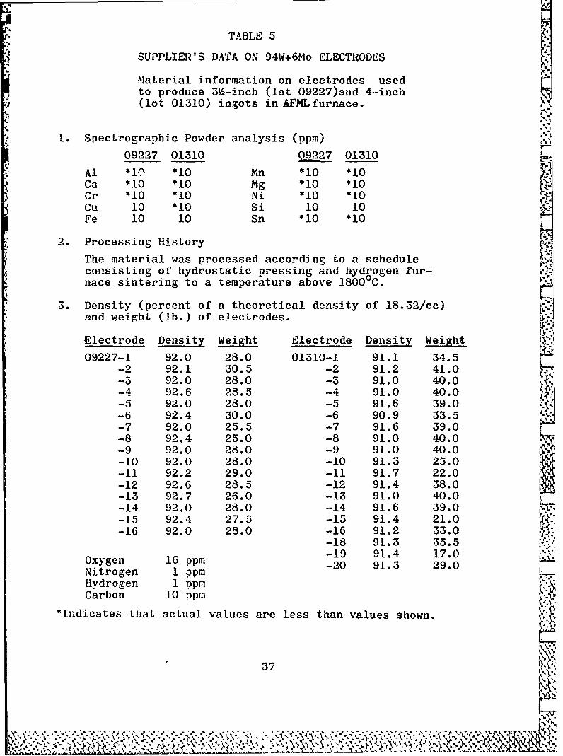
TABLE 5
SUPPLIER'S DATA ON 94W+6Mo ELECTRODES
Material information on electrodes usedto produce 3 -inch (lot 09227)and 4-inch(lot 01310) ingots inAFMLfurnace.
1. Spectrographic Powder analysis (ppm)
09227 01310 09 01310
Al *10 *10 Mn *10 *10Ca *10 *10 Mg *10 *10Cr *10 *10 Ni *10 0Cu 10 *10 Si 10 10Fe 10 10 Sn *10 *10
2. Processing History
The material was processed according to a scheduleconsisting of hydrostatic pressing and hydrogen fur-nace sintering to a temperature above 18000 C.
3. Density (percent of a theoretical density of 18.32/cc)and weight (lb.) of electrodes.
Electrode Density Weight Electrode Density Weight
09227-1 92.0 28.0 01310-1 91.1 34.5-2 92.1 30.5 -2 91.2 41.0-3 92.0 28.0 -3 91.0 40.0-4 92.6 28.5 -4 91.0 40.0-5 92.0 28.0 -5 91.6 39.0-6 92.4 30.0 -6 90.9 33.5-7 92.0 25.5 -7 91.6 39.0-8 92.4 25.0 -8 91.0 40.0-9 92.0 28.0 -9 91.0 40.0-10 92.0 28.0 -10 91.3 25.0-11 92.2 29.0 -11 91.7 22.0-12 92.6 28.5 -12 91.4 38.0-13 92.7 26.0 -13 91.0 40.0-14 92.0 28.0 -14 91.6 39.0-15 92.4 27.5 -15 91.4 21.0-16 92.0 28.0 -16 91.2 33.0
-18 91.3 35.5-19 91.4 17.0
Oxygen 16 ppm -20 91.3 29.0Nitrogen I ppmHydrogen 1 ppmCarbon 10 ppm
*Indicates that actual values are less than values shown.
37
~L__~: ,

TABLE 6
TYPICAL mELrING R13CORD OF W+6%Mo+2%Cb
(Using 316 inch mold)
Heat number VA-73Electrodes 09227-2, 09227-8Electrode size 1.44 x 55.5"Leak rate .5 micron per minuteMold size 3.5 x 18" ..
Electrode __
Time Pressure Stirring TravelMin. Sec. Amperes Volts (Microns) (Amperes) (Inches)
0 0 4000 24 0.005 2 0
1 30 4800 28 2 0
2 20 5200 28 0.08 2 -
3 00 5800 28 0.1 2 33
8 00 5800 26 0.06 3 69 00 5800 27 0.08 3 9
II 10 5800 27 ---- 3 11
13 45 5300 28 0.06 1 15
16 45 5800 28 0.08 2 18
19 15 5800 28 0.07 1 22
22 00 5800 28 ---- 1 26
28 00 5800 28 0.05 1 30
30 25 5800 28 0.05 1 39
31 00 4600 -- 0.03 --
* 32 15 2500 --- ----
33 20 POWER OFF 0.03 -
38
0%

TABLE 7
HARDNESS OF 92W+6Mo+2Cb BILLETS
Billet BHN,* Top BHN, BottomBile
VA-69 285 285
VA-70 280 290
VA-71 285 300
VA-72 290 272
VA-73 285 285
VA-74 272 285
VA-75 302 308
VA-76 295 320
VA-84 300 290
VA-94 272 285
VA-95 280 290
VA-96 302 308
VA-97 285 285
VA-98 285 300
VA-99 300 290 -
* 10mm tungsten carbide ball, 3000 Kg. load
,9 '
39 ,-,\

N V*40 l -1 - - - 4 to to U) L. ) o t4o f o toU )
I ~ ~ ~ ~ ~ ~ ~ * *4I -- I 4*J -- 1 -- 4 V *- 4-0 I,1 OU OU ! e r )t
1 0 OD N0'N0 V-UU) N 0 coO00 D 0 fl0w)0 Em * c N-
a M
00J4 000. 0 V) 0f U) ' O (0 0 t 0 V)0 ) 0 V)0 0) 0 -4U)V 0
-4 a) CQ M) N) 10 4" -4 -4 -4QN -t* - 4 4 --4 q 0iqC 4C3 4 4
--
D 2 O IC 00 n1), 4-4-4al-CO OD4 OD4a) V-- - 0 -4 - a (D M4-4
0 O- OC 0 D4t)t 4 )U tC a)~C1 -4-44M-4 3 IC4 1010 CI tO -0) L1 >0
4J4 o 10, to) )cq t N ( O D at) 1 0 ( 0t~ I 0 0'If ( 0 l04 Nt)() ) a ) (M 1-1 uqFi 4
w00-41044
-0 03 M -4 CJC - 40(0t) 02,I-I4NaC-4 -4 nCq -C40).( I I - -
4J0 ON 0 e 0 q V-4 N 4 (Dit 1 0 to I0 ~ I f 001U) 1 0 t) 4 .d
0.00 00 00 N0 00 00 00 1N 0N 0 N 00 N NNI- N 0CI n -4I4ci C 4 I to 03 Il W Iq I4 I CA 0~
0 -
40-1'C I ! O t 1 i 1 !C
U)0 Irtr OL M r I O t O oU) t r)V )h

a )a a uuC a 0 oo4-1
%I a 7 a a sc a s c 0a cc a c 0 a s 0 a a 3 c. c a 0aN .0 4 f. #I~. I- 1 111- 1 . 0.,,
a to aa s a a a a to to a 0 WAa a a aa c a a -
.4.~4 '*~).6~0l N t, ID to U) 0 to W)V) W') b0 W) b') W) V) o D h0 WN ' V) 0 fb 0 0' 0 W)
-l -D 9040 %0 9 , % -( , r , E -t . o t .t o ' )r c o t
.5 U -4~. .4 ~ Id..~0 V a le V v a V a - 3 V a v v4 - 4.-.4-. .oc x x x Nx x xx x4 .l .7 -4o
x * - -4 -4 -4-4 -4 - 4 -4 * - -4 . . .* 4 -4 -4 4-4
ax a
moD0t oIN00c ,0I 0 011 Go00 Im Oa I-c -V t
x4 '0
~ Iit, aI
z~o 00c0 w .a1
a *0a000 0000000 0o 0 .aspis 00 00S. TvV "N0t -40 w- to3 30 003033300 00 t va 'D CD0~
0 M 40 .4,.C
m~~~~~~~~~~l~~ ~ ~ :01 -4N00v m0NN 0000wN vt 0 a 0 to0
411 M c ' 0; [Z. 4f ID V; 0o C'D 00- L.).0 k U 0 D I I~ O D 0 4 *
E-4 N x a r& = ;.-NC 0I JN JN NN NN
-40 0
0. ID l-4 't 0 8 0 0 0 04Nt 0 0-4 N J' No a .0. M.4 -x~~~ ~W (A DD~ 011)11100000001444444-----. CO C4
0at .1 -7 v V IV4v v 0 v v " v0 0 000000000000 4J -Cd4C.,. f S'
41 . 9
bO= r.a C).

4
TABLE 10
TYPICAL MELTING RECORD OF W+6,Mo+2%Cb
(using 4-inch mold)
Heat number VA-99 [TTElectrodes 01310-12 and 01310-14Electrode size 1% x 39Y&Mold size 4 x 18"
Electrode
Time Pressure Stirring Travel(Min.) Amperes Volts (Microns) (Amperes) (Inches)
0 4000 28 .005 2
4700 27 .03 2
1 4800 28 .03 2
2 5300 28 .03 2
3 6300 28 .035 2 _
3)3 6300 28 .03 4 2"'AIS
6 6300 28 .023 4 4
7 6300 28 .03 3 5
9 6300 28 .03 2 7
14 6300 28 .026 2 14Ya
18 6300 28 .03 2 19
20 6300 28 .03 2 21
21 6300 28 .03 h22
22 6300 28 .04 24
23 4100 28 .02 3 25
23A 3100 28 .02 6 25
7 233 2500 28 .016 25
253 Power Off -- .024 --
42
Ikl

TABLE 1
92W+6Mo+2Cb EXTRUSION HARDNESS
(Rockwell A)
Sample Edge Center Edge , -.,
898 nose 72 72 71""
898 center 72 72 72
898 tail 70 72 73
899 nose 72 72 72
899 center 71 71 71
899 tail 71 72 72 vA_
900 nose 68 67 71
900 center 70 70 71
900 tail 71.5 72 71.5 .
911 nose 70 70 71
911 center 70 70 70
911 tail 70 69 70 F_
913 nose 70 69 72
913 center 72 70 72
913 tail 70 70 71
916 nose 71 71 71
916 center 71 70 72
916 tail 71 70 71
928 nose 71 70 70
928 center 70 70 71
928 tail 71 68 71 I.
43 v*
L7

1:$104- 0 0 0 00 4) a Go0 0 0 0
4 C 1 0 O 0 D (O00 t
V)"4a "4g N- 't M N ) ( o LO
0) '~ 0 000'o 'D0 0 0 0 *
:s 10 JN N- C- oa m Cl It "4 )
4- o "4 r- W r- 0 0 0 o
00
00 0~~KoD 0021
m qt00 o t 0"4a 0200 004 I~Z~ t2 C13 024 P- Z~ 0 0
0 0)00
(0j "4 Ntol .~
T ~000 to) Or Cl Ca 0r 0CX ,g"4i N P- 4 0 -
0 00 0 o.0 ~j0 0 Ca o1 00 o
+. 41f. Go ~ ( 0 :s0. 00 m ~ (0
0 0 0 t 0 OC . b(0 1 0 Cl tl0 W
E-4 "4 "4 0 0 *0 Im 0 r_4) $.l r-&~
ao) ~ ~ ~ ~ ~ U *o 0 c,''t t 00 .~~- 0) rd~
0 0 0 4 -)U
+I0 ' 4. V4 "4) 0
E-4 00 (D *H It0)
0 0 ~ 0 & to. 0 x z0f ~
440
091*
to LO~

J
TABLE 13
RECRYSTALLIZATION BEHAVIOR OF W+O.6Cb
Showing Percent !ecrystallization in As-Extruded SamplesHeated for 1 Hour at Indicated Temperature
Percent Recrystallization
Sample As-Extruded 28000 F 3000O F 32000 F 34000 F .
995 N 20 25 40 100 100C 70 75 80 100 100T 0 10 50 100 100
997 N 5 10 90 100 100C 40 50 60 100 100T 0 20 80 100 100
750 N 5 20 50 80 100C 10 25 40 75 100T 0 20 50 80 100
754 N 0 20 50 80 100C 10 25 50 75 100T 0 20 50 75 100
756 N 0 30 50 70 100C 5 35 55 85 100T 0 40 50 80 100
,"..
757 N 5 30 45 70 100C 10 25 45 75 100T 5 20 45 70 100
758 N 0 20 50 70 100C 5 25 50 75 100T 0 30 50 75 100
759 N 5 30 55 80 100C 10 30 55 80 100T 5 30 45 75 100
763 N 0 25 40 70 100C 5 30 40 70 100T 0 30 45 75 100 -
N, C, T Nose, Center, Tail Samples :
45: ..:..
L01,, ; - : .-..: .::.....- ::?£, < -::. - - .:: z : :.:: j ::..<:-.:,.. :: :-.--:. :, .-,-1.

"SA
TABLE 14
EFFECT OF REDUCTION ON W+0.6Cb HARDNE SS ,
(Forging and Rolling)
Rockwell A Hardness of Forged W+0.6Cb(Average of 3 Readings)
Orig. ForgeHardness Temp. Hardness at Percent Reduction
Sample (Annealed) (OF) 20% 40% 60,6 8096
761 70.3 2600 71.0 71.0 72.3 72.7
763 71.0 2000 70.7 70.3 71.0 73.3
* 763 71.7 2400 71.0 70.7 71.0 72.0
993 70.0 1600 71.7 72.0 72.0 73.3
993 71.0 2400 71.0 70.0 70.7 72.0
Rockwell A Hardness of Rolled W+0.6Cb -V(Average of 3 Readings)
Orig. RollingHardness Temp. Hardness at Percent Reduction
Sample (Annealed) (OF) 20% 40% 60% 80%
759 71.0 1600 71.0 -
759 70.7 2000 71.3 71.7 72.0 ----
759 71.0 2400 70.7 71.0 72.3 72.7
761 72.0 2000 72.0 72.3 ---- ----
763 71.3 2400 71.7 ---- ---- ----
992 70.7 2000 71.3 -------- ----
993 70.0 2400 71.0 71.3 ---- ---
46
.... ......... ...

W OD t)J 0 1 0* to OD l -
r, w t CD to ~ C DO
0
0 0t01 I to (D CD (0
tt 13 I r I ,I)) o CD N C I N o t- O
) . - 1 0 00 00 0
0) ~ CD to t CD 1l0 to (0 C
0
,o00 CONICD CO.t IO C- ONNCI) (D CD CD (0 I D CD c to
0
+ 00 '0 '0 O Io 0
-0 0 )to0 DoS r .I 0 t N. D I to to D t
0 0 -4 - 0 1 0 00) N 0)
50 u 4 I - 0 0 0
toE) 0 to o I 0) CD ) 00 (
I NNo CD lD w (DD to~
0 0 0
) 0 01 IP. 0 0 I0 1 0 00 001 Et4 'o. to0 0 I CD CD ID w m00
0 UN t (0 1u- COO
oi ooo
0o
(. E 0 1 P4 '0 0 -.
:4 a4) 1 a 0 P-4P4.c
C4 0)
477
E- 1

TABLE 16
ROCRYSTALLIZATION BEHAVIOR OF 92W+6Mo+2Cb ALLOY
Showing Percent Recrystallization in As-Extruded SamplesHeated for 1 Hour at Indicated Temperature
Percent Recrystallization
Sample Extruded 26000F 28000F 3000°F 32000F 3400°F
898 N 10 10 25 40 90 100C 20 20 30 40 90 100T 0 10 25 40 90 100
899 N 15 15 20 40 90 100C 40 40 50 60 100 100T 0 10 25 40 90 100
900 N 15 15 20 50 95 100C 40 40 45 50 100 100T 5 10 25 50 95 100
N, C, T - Nose, Center, Tail SamplesA.A
%V-Vft'
48 4-
Z: 4 7:?..' ,:, '. -. '- './ ,,.. : >>. v., '.,. - ,-,'.' v,.' n y~w . ',.':':c- ', -..-.- ,,:.,.: "r

0 000~~~~ ~ ~ S 00m1 0 r DciO oV
0t 0
0 0 +)4404 .0 0 0
go ' ItUC%- t; Or c .t; 0- t- t ,1 N N N
0oo] - - 4 .4 -e4-4-4 2
00 4-) 0 0
41 S. N -48 ) U ) C 0 - ~ (0 ! 0! 0! ' N" 0) to 0 ) CD o C4 c ) v- tO _ 0) f- 0 . c4 N N C
v ~ ~ ~ ~ ~ ~ ~ ( 00 OD 00 0 .4DOD V q I , D O -
4-) -4 4 4 4- - - 0. * I-0 ;.0I
00 0 10 CD (00 0 193 0 I M04 ( t 4 t 0 4
o~~~~~ 0040 0 ~~... 4+ 4-)o 30 .0O~
:1 co 0 0 0' 00 4 U) 0- 001 bV b 0
4. 0- 0( .") N) U) 1-4 CO - 0 %240S. C)" o o-4 .I I t, NW N- -I .E, 0) 0 .
19~~~ 0z0 .00 . . . . . . . t: ; t
0 0 0 .4 8 0.420 0
0too 0 0 0 0 0 00 00 0-64 0 N *N
C/) o
.' 000 ru - .4 C0 ~0 . .0 0 bD - bO0
Cal 0 0 00080880 0 04 0U 1.4 .48 u t O30) 0 4. 0 0 00 4 1- 0 N t 0 (D , to N
401 ) C". 0 C; NO t 0 V; C 0- 0( ;" -4b 4 - . 0V .0v
4 N IV o) N 0 to to. to( NO to ) U) (D @ 0z
-402~ ~~~ r. $2 0 0) a4 ) U 4 I ' U ) U ) ( 0
I-4~~~ 00 o000 00 Q Q Q Q3QQ000
a,2 040 U 0 8 ) 0 (0 N 0 0 8 O U) 0 00 80~ 0 L 4\cft~ 0 ' 0 U '0 0) U 0 00 a0 U )U ) 0 C 'c>4 ccN C' 0 ' U) (0 No (4D 1 0 (0 N v 0 N 0
0~0 0(%' 0 ; .
z .4 0 0 0 0 0 0 0 .0 4 J. 0 .i 0
41) gC'1 V O N 01 O - 0 U) N0 -. ID V a) 0 04 : Xu)o M) vUo t V1, ) In 10 to & 0 0
E-1 4J 0 N40( U) N ) U o '' OC.
a 0D0024 0 to M 0
) (0 -M 42 S 4 J. -A 0-Iato (0 ) CON N- 0 N U) U D) '0 es V' v' 0' t.~ 14'o 0
04J '.1 0 0 0 0 0 N -4 -4 -4 N N 0 0r 0 0 0U) l I1 " " m v -" 4 " ) I 0 -0 4 -4 -4 Wto(o00a A
040 . .4 4. -4 '-4 '. 'I C) OD (U O -4 o ~ 4 -. 4 0
0. 0 0 0
~IIto A4
w I wU) C,3 U3 0.0 0 0 '0N 0 coos 'S '5 -
Go0 U 0( 0 ) U) C4-0 A 0 " ) " v N N Nf N 0VVr-I U) coU) 1 0 0m 0 c 4 -0 0) ) (0 to U) 0 a) U
(D I 0 0 0 0 0 I' b" .54 C':0( (
A49" nz0 0 41

TABLE 18
BENDIX Cr+MgO EXTRUSION DATA
Billet Composition, 93.5% Cr+O.5%Ti+6%MgOUnless Indicated Otherwise
*Indicates Rectangular Extrusions
. Bendix Max. Min. Peak K* Ext. Billet Density Temp. Force Force Factor
No. No. jj Ratio (OF) (Tons) (Tons) (psi) Comments
808 442 84.4 *11.7:1 2400 340 280 37,000 Gd Surface
809 444 83.8 *12.1:1 2400 390 310 42,000 Gd Surface
810 430 85.2 *11.7:1 2300 390 310 43,000 Gd Surface
811 431 84.7 *12.1:1 2200 435 390 47,500 Gd Surface
829 455 83.8 *9.2:1 2000 580 550 70,500 Gd Surface
830 456 82.8 *8.1:1 2000 590 540 77,000 Gd Surface
831 457 83.4 *8:1 2000 620 540 80,500 Gd Surface
832 458 83.4 *8:1 2000 580 540 75,500 Gd Surface833 459 83.4 *8:1 2000 590 540 76,500 Gd Surface
834 460 82.9 *8:1 2000 590 530 76,500 Gd Surface
844 481 82.1 *8.4:1 2000 590 530 75,000 Gd Surface
" 845 482 83.5 *8:1 2000 600 540 78,000 Gd Surface
846 483 82.9 *8:1 2000 580 525 75,500 Gd Surface
%W 847 484 82.9 *7.8:1 2000 580 530 75,000 Gd Surface
849 485 84.0 *8.6:1 2000 600 570 75,500 Gd Surface
850 486 84.2 *8.7:1 2000 600 590 75,500 Gd Surface
851 487 85.0 *7.8:1 2000 600 540 79,000 Gd Surface
852 488 85.4 *7.8:1 2000 600 560 79,000 Gd Surface
853 489 86.6 *7.7:1 2000 620 580 81,500 Gd Surface
854 490 84.6 *7.4:1 2000 610 570 82,500 Gd Surface0 855 491 85.6 *8.5:1 2000 610 530 77,000 Gd Surface
856 492 85.6 *8.3:1 2000 620 560 79,500 Gd Surface
857 493 86.5 *8.3:1 2000 610 540 78,500 Gd Surface
858 494 86.5 *8.3:1 2000 590 530 i5,500 Gd Surface
so1:,-.50
V
- ~. *RIOp.

TABLE 18 (continued)
BENDIX Cr+MgO EXTRUSION DATA
Bendix Max. Min. Peak KExt. Billet Density Temp. Force Force FactorNo. No. (%) Ratio (OF) (Tons) (Tons) (psi) Comments
859 495 84.4 *8.3:1 2000 590 570 75,500 Gd Surface860 496 86.5 17.8:1 2000 600 540 79,000 Gd Surface
861 506 86.6 *7.7:1 2000 600 520 79,000 Gd Surface
862 507 88.4 *7.7:1 2000 NR NR - Gd Surface
863 508 87.4 *8.8:1 2000 610 570 76,000 Gd Surface(Uncoated Die)
866 512 82.9 8.2:1 2200 630 NR 80,000 Gd Surface(Trouble GettingBillet InContainer)
867 513 82.6- ------ 2300 --- Stuck868 497 83.5 8.2:1 2000 575 480 73,500 Gd Surface
(Uncoated Die)869 498 84.2 8.2:1 2000 670 610 85,000 Fr Surface
(Uncoated Die)870 499 85.4 8.1:1 2000 610 480 78,000 Gd Surface
(Uncoated Die)871 500 84.4 8.1:1 2000 610 450 78,000 Gd Surface
(Uncoated Die)872 513 82.7 2450 660 500 ------ Very Badly
Cracked(Uncoated Die)
883 521 83.5 9.3:1 2500 580 530 70,500 Pr Surface(Fir Tree Effect)
884 515 77.0 9.3:1 2500 370 330 45,000 Gd Surface
885 516 773 9.3:1 2500 370 330 45,000 Gd Surface x886 522 79.0 2700 660 570 ------ Fir Tree
Effect (Entire Surface)887 502 82.9 *9.1:1 2000 560 495 69,000 Gd Surface
888 503 82.8 *9.1:1 2000 560 480 69,000 Gd Surface889 504 84.6 *9.1:1 2000 570 490 70,000 Gd Surface
890 505 82.8 *9.1:1 2000 545 440 67,000 Gd Surface
51
4 ,

TABLE 18 (continued)
BENDIX Cr+MgO EXTRUSION DATA
Bendix Max. Min. Peak KExt. Billet Density Temp. Force Force FactorNo. No. j Ratio (OF) (Tons) (Tons) (psi) Comments
897 540 77.9 *9.2:1 2500 550 350 67,500 Gd Surface902 532 81.5 *9.4:1 2000 510 400 61,500 Gd Surface903 533 81.5 *9.4:1 2000 420 380 51,000 Gd Surface
904 534 81.2 *9.4:1 2000 500 430 60,000 Gd Surface
905 535 81.6 *9.2:1 2000 540 460 66,000 Gd Surface
906 537 83.8 *9.2:1 2000 580 460 70,500 Gd Surface
907 538 83.0 *8.5:1 2000 510 400 64,500 Gd Surface
908 539 82.9 *8.5:1 2000 560 500 70,500 Gd Surface
920 554 10:1 2200 455 450 53,000 Gd Surface
921 555 10:1 2200 435 435 51,000 Gd Surface
922 557 10:1 2200 395 370 46,000 Gd Surface
923 558 10:1 2200 390 380 46,000 Gd Surface
924 552 10:1 2200 400 380 46,000 Gd Surface
925 553 10:1 2200 380 380 45,000 Gd Surface944 --- 10:1 2200 440 410 52,000 Gd Surface945 --- 10:1 2200 440 410 52,000 Gd Surface
1013 542 85.4 *9.6:1 2200 410 340 47,000 Gd Surface
1014 543 77.9 *9.6:1 2200 400 320 45,000 Gd Surface1OOCr
1015 544 81.0 *9.6:1 2200 400 360 45,000 Gd Surface1016 547 81.3 *9.6:1 2200 400 360 45,000 Gd Surface
Cr+9MgO1017 564 87.6 *9.6:1 2200 420 360 49,000 Gd Surface
Cr+8Th021018 566 *--- "9.6:1 2200 420 360 49,000 Gd Surface
10OCr
1019 567 81.3 *9.6:1 2200 400 340 45,000 Gd SurfaceCr+3MgO
1020 568 81.6 *9.6:1 2200 400 360 45,000 Gd Surface
1021 569 70.4 *9.6:1 2200 400 340 45,000 Gd Surface
52

TABLE 18 (continued)
BENDIX Cr+MgO EXTRUSION DATA
Bendix Max. Min. Peak KExt. Billet Density Temp. Force Force FactorNo. No. (,) Ratio (OF (Tons) (Tons) (psi) Comments
1067 570 78.7 *10.0:1 2200 560 430 66,080 Gd SurfaceCr+ 6MgCr20 4
1068 575 79.3 *10.0:1 2200 535 355 63,130 Gd SurfaceCr+5Mgo -
1069 576 81.0 *10.0:1 2200 555 355 659490 Gd SurfaceCr+4MgO
1070 577 79.0 *10.0:1 2200 550 360 64,900 Gd SurfaceCr+2MgO
1071 578 79.1 *10.0:1 2200 545 355 64,310 Gd SurfaceCr+ IgO
1072 574 77.9 *8.0:1 2500 525 445 61,950 Gd Surface
(Some Temperature Loss)
: .
53
V " * r*" "; v -;"e ""- ' ,,-- ' , . .,- .- ., . .- T

TABLE 19
MISCELLANEOUS MOLYBDENUM ALLOYS
fax Min Peak KExtr. Billet Billet Temp Force Force FactorNo. Agency Composition Condition Ratio Glass (F) (Tons) (Tons) JPSI) Comments
848 W fo+25W+.IZr AC 7.5:1 7900 4000 500 410 67,000 Good Surface
910 M ,o+.STi (1) 7.7:1 0010 2200 540 320 71,000 Extrusion Cracked985 AEC Molybdenum l 8.8:1 7810 3200 410 400 55,000 Tubing, Gd Surface
986 AEC Molybdenum f1R 8.8:1 7810 3000 550 480 69,000 Tubing, VG Surface
991 CH Mo+.26Zr+.04C AC 6:1 7900 3800 480 400 74,000 Temp & FrictionStudy
1023 GE Mo+lZr+.IC AC 10:1 7900 3650 610 510 71,980 Fair Surface
1024 GE Mo+l.25Ti+.5Zr AC 4.3:1 7900 3500 470 430 89,000 Fair Surface
1025 GE Mo+l.25Ti+.5Zr AC 4.3:1 7900 3500 460 420 89,000 Fair Surface+.IC
1029 CM Mo+O.OSC+l.SCb AC 4:1 7740 3000 495 425 91,500 Fair to Gd Surface+0.STi+0.3Zr
1030 CM Mo+O.IO+1.25Ti AC 4.2:1 7740 2800 505 430 93,500 Good Surface+0.3Zr
1032 CM Mo+O.IBe+0,003C AC 4.2:1 7740 3000 480 300 90,800 Good SurfaceJacketed
1035 CM Mo+0.05C+1.SCb AC 4:1 7052 2600 610 510 119,000 Good Surface+0.5Ti+0.3Zr
1036 CM Mo+O. lOC+l.25Ti AC 6:1 7052 2800 650 645 98,300 Stuck .,
+0.3Zr
1037 CM Mo+O.IOC+l.25Ti AC 4:1 7052 2800 565 490 110,000 Good Surface+0.3Zr
1038 CM Mo+0.10C+1.25Ti AC 4:1 7052 2800 540 490 110,000 Good Surface+0.SZr V
1039 CM to+0.05C+l.5Cb AC 4:1 7052 2800 570 500 111,000 Good Surface+0.STi+0.3Zr
1040 CM Mo+0.OSC+l.SCb AC 4:1 7052 2800 565 500 113,200 Good Surface+0.5Ti+0.3Zr
1041 CM Mo+O.OSC+I.SCb AC 4:1 7052 2800 570 505 114,000 Good Surface+0.5Ti+0.3Zr
1046 CM Mo+O.IOC+1.25Ti AC 6:1 7052 2800 700 --- Stuck+0.3Zr
1054 AEC Molybdenum H1R 8.8:1 None 3000 600 530 75,000 Tubing, Gd Surface
1055 AEC Mo+.S%Ti HR 8.8:1 None 3500 510 415 63,800 Tubing, Gd Surface ,K,
1056 AEC No+O.STi+0.O8Zr 11R 8.8:1 None 3750 520 340 64,900 Tubing, Fr Surface
1057 AEC Mo+0.5Ti HR 8.8:1 None 3500 500 370 62,400 Tubing, Fr Surface1058 AEC No+O.sri 11R 8.8:1 None 3500 535 420 66,800 Tubing, Fr Surface
1059 AEC Mo+.STI+.O8Zr R 8.8:1 None 3700 550 470 66,800 Tubing, Fr Surface
1060 AEC Mo+.STi+.OBZr 1R 8.8:1 None 3700 No Reading Tubing, Gd Surface
(1) Composite billet
Agency Code W = Westinghouse, M Marquardt, AEC = Atomic Energy Commission,CM = Climax Molybdenum, GE = General Electric
Surfaces rated according to standard established in Figure 13.
54
%K

TABLE 20
MISCELLANEOUS TUNGSTEN ALLOYS
Max. Min. Peak KExt. Billet Temp. Force Force Factor AlNo. Agency Coposlition Ratio Glass j2F) (Tons) (Tons) (psi) Comments
812 C W+.089Hf+.002C 4.2:1 7740 3600 410 360 77,000 Gd Surface (He Jacketed)
813 C W+3.2Mo+.IO2Hf 4.2:1 7740 3600 410 345 77,000 Gd Surface (Me Jacketed)+.002C
814 C W+3.2Ho+.O6Zr 4:1 7740 3600 410 345 80,500 Gd Surface (Me Jacketed)+.003C -
815 C W+.99Cb+.06C 3:1 7900 4000 NR NR Gd Surface
864 WC W "6.2:1 7740 3400 465 400 68,000 Gd Surface
865 WC W "6:1 7741 3200 480 415 72,500 Gd Surface
873 C W+1.OCb+.002C 4.2:1 7810 3800 395 330 74,000 Very Gd Surface(Ho Jacketed)
874 C W+3Ho+lCb+ 3.8:1 7810 3800 365 330 72,000 Gd Surface (Me Jacketed).002C
875 C W+.IHf+.002C 6.5:1 7740 3600 460 430 67,500 Gd Surface (Me Jacketed)
876 C W+3Mo+lCb 8.7:1 7810 3800 500 460 62,500 Gd Surface (Me Jacketed)+.002C
877 C W+3No+.Iilf 8.6:1 7740 3600 560 495 70,000 Gd Surface (Mo Jacketed)+.002C
878 C W+.O5Zr+.002C 9:1 7740 3600 560 495 68,500 Gd Surface (Me Jacketed)
879 C W+I.OCb+.002C 8.4:1 7810 3800 495 460 63,000 Gd Surface (Me Jacketed)
880 C W+.lHf+.002C 9:1 7740 3600 530 495 63,500 Gd Surface (Me Jacketed)
881 C W+3mo+.IHf 8.7:1 7740 3600 560 525 70,000 Gd Surface (He Jacketed)+.002C
882 C W+.O5Zr+.002C 9.2:1 7740 3600 560 525 68,500 Gd Surface (Me Jacketed)
891 C W+3Mo+.O5Zr 9.1:1 7740 3600 545 480 67,000 Gd Surface (Me Jacketed)+.002C
892 C W+.O5Zr+.OIB 9.4:1 7740 3600 545 480 65,500 Gd Surface (Me Jacketed)893 C W+3Mo+.OSZr 9.3:1 7740 3600 620 590 75,500 Gd Surface (Mo Jacketed)
+.002C894 C W+.O5Zr+.OIB 9.2:1 7740 3600 570 540 69,500 Gd Surface (Me Jacketed)
918 W Sintered W, 6.5:1 7900 4000 430 380 63,000 Fair Surface88% dense
975 W Sintered W 6.5:1 7900 4000 500 450 73,000 Fair Surface
1011 W Sintered W 6.5:1 7900 4000 530 430 78,000 Fair Surface
1031 C W+.003C+3.0Ho 4.2:1 7740 3400 400 360 73,400 Gd Surface (Me Jacketed)+O.05Zr
1033 C W+.003C+3.0Mo 6.5:1 7740 3200 530 430 76,900 Gd Surface (He Jacketed)+O.05Zr
104 C W+.003C+3.Omo 6.4:1 7740 3100 590 520 87,000 Gd Surface (Mie Jacketed)+O.05Zr
1064 L W+6OppmC+2OppmO 4.2:1 7740 3200 390 335 72,000 Fair Surface*+.lSmo
All billets from arc melted ingots except 918, 975, and 1011.
Agency Code WC = Wah Chang, C - Climax, W = Westinghouse, L - Ladish
Surfaces rated according to standard established in Figure 13.
55
' %

0 C0 0
ri~ 0
04) rx.aE o CX fU 1#40
0 S 0 0riZ 0 C . C. 0. 0. C. . 4 0 . p
0 >0 04 0. 14 04 1 14 04) 1400)14+)-00 0 0 0 D0 0
CL CT i t~ 10 (D N - CO O E- rnC 10
b00 0 0 000 00 ho100
$04 0 I -4 1C') w1 N l0 E0
x l00000 0 0
(nf3l L 04 0 0 wO tO CD m~ N 0! 0 CO C 0 0 f 00 0 0001 E-40 Z LO 0 t
'U 000 0 00 0 00~0 00 00 0 0
14 0 0 0ci0 0w 00c 100 04 C11 to
491 0*. 0 ; ; t o o t f0: N N a) It 021co00to1 0 co , t 10 Go
0 * 0
* 44
4CD C'C) 0004 04 C
P-4 0 p4) 0 0 w u 4 + 0 t
co S,+ +4 .+ . 0 .0 0 0 + +
4; C;'- 0 t 00 0 0 (D E' LO '0 Ll 0 M
56

TABLE 21 (continued)
INTERNAL SUPPORf PROGRAM
Temperature and Friction Study Data
Breakthrough
Temp. TonnageExtr. Composition Ratio Lubricant (OF) Stem Die
952 1018 steel 8:1 8871 1600 640 360953 1018 steel 8:1 8871 1600 580 350960 Copper 6.0:1 Graphite 800 540 240
961 Copper 6.0:1 None 1000 S00 200962 Copper 6:1 Graphite 800 540 240963 1018 steel 6:1 Graphite 1600 540 340967 Copper 6:1 Graphite 1200 450 175968 Copper 6:1 None 800 450 310969 1018 steel 6:1 Graphite 1600 460 340
970 1018 steel 6:1 Graphite 1600 540 330971 1018 steel 6:1 Graphite 1600 470 280972 1018 steel 6:1 0010 1800 340 240976 1018 steel 6:1 None 1600 540 300977 1018 steel 6:1 0010 1600 410 280978 1018 steel 6:1 None 1800 350 260979 1018 steel 6:1 0010 1800 430 260980 1018 steel 6:1 None 1950 370 230981 1018 steel 6:1 0010 1950 290 180988 1018 steel 6:1 0010 1600 340 280989 1018 steel 6:1 None 1950 340 240990 1018 steel 6:1 None 1950 320 250
1000 1018 steel 6:1 None 1800 570 255 LII1001 1018 steel 6:1 None 1600 640 2601002 1018 steel 6:1 None 1600 640 2601003 1018 steel 6:1 0010 1600 640 NR1004 1018 steel 6:1 0010 1600 500 260
57
) % $ \ ' . q ' i l L : , " , ', '- .'', -'. 'V .%' " j .. '.,' ",V " : . '- , 2 - . .$ .7 . .- 'T . .. -4 .-\ .'., - -'. .. ,. . . ... . .H .
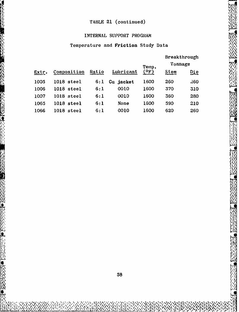
t-L4
TABLE 21 (continued)
INTERNAL SUPPORT PROGRAM
Temperature and Friction Study Data
Breakthrough
Temp. TonnageTemp.
Extr. Composition Ratio Lubricant (OF) Stem Die
1005 1018 steel 6:1 Cu jacket 1600 260 260
1006 1018 steel 6:1 0010 1600 370 310
1007 1018 steel 6:1 0010 1600 360 280
1065 1018 steel 6:1 None 1600 590 210
1066 1018 steel 6:1 0010 1600 620 260
Li
)l _
S- 7

StemDummy Block Billet
(Ram) Follower tWteriaI i
DCel
LL
Figure I Schematic Illustration of an Exctrusion Process
59*.
k Z 'Y

.4~'.
&~'-4up .U*e 44.gt V t*
4.O
tt'
- (extrapolated)
(-
Figure 2 -Data Trace Schematic, Showing Distribution of ForcesK During Extrusion for Determination of Billet Friction.
A.-
60
LIC~4 - ----
-. N4

04-
4) 0)
UV0
.002
C-4 0
ow 0
U4
061

Leads toGraphiteVisicorder/ /
I,. Billet
Contai er/ Load Cell
Backup Tooling
Extrusion
Container Liner
F'igure 4 -System for Die Pressure Measurement. Force on Die isN-Transmitted Directly to Load Cell to Which Strainr
* Gages are Attached, While Force on Container and Linerare Transmitted to Backup Tooling.,~r
62 :
, #

0
I j
V
'4
.)
-1V
S A
1 .4
'-'9
e.4..
Vp .4
Iip
I~~~~1
Figure 5 - F'enn Model 6?, 2-Die Swaging Machine. ~163
. .4 . . .
.................................................
. .4 ...........................................
.4 .4.4.4.4.4 . . . . , . . . - . . . . .4

A-r
.44.
~ In.4.,
All- 5.,4
Figure 6 -W+O.6Cb Ingot Macrostructure. Ingot Produced by OremetUsing Alternating Current on Left, Ingot Produced at AFMLUsing Direct Current, Straight Polarity on Right.
64
*4N
71

ciMN
N OM P
V0 N t %( W
+0f b i~-
00
CL '
7N 00
0b
A9 0V
E-4
zS0(
N 0
: 3 rI
8 00
rq P4 P4 K Factor, I x ur-3psi 0
Figure 7 Relation of Temperature and Extrusion Constantfor Universal Cyclops W+O.6Cb.
65
* .4 * \jv v

Ig -Co -
:q4
0N
P-4
0am) CoO
4 to
w 03
030
*~~ 4 )
K Factor, I x O-psi ,,
Figure 8 - Relation of Temperature and Extrusion Constant, i 2Other W+O.6Cb Suppliers Plotted on UniversalCyclops K Factor Band.t
66.,
: ho
4---

Max.. Ton
5[-Nose MaxiTn Ton50-Bloc ~ .I.Tn
IS m400-
ToolingDie Contact
Tons 300-
200-Followerlock
0.1 0.2 0.3 t~4 0.J 0.6 0.7 0.8 0.9?ime, ece
Stem & Die Pressure, Extrusion 1050
500 9
400 994Y
300
200 LULI.2 17 ,1U 03 .40. 0
Jime; Sec.Stem and Die Pressure Curves, Extrusions 992 - 997 *
60
K 995FactorINpsi x 10-3 5
45 3b 37 38 4Temperature, IPF x YO2 4
Die K Factor vs Temperature
Figure 9 -Stem and Die Loading vs Time and Die K Factor vsTemperature For W+0.6Cb Extrusions.___
67
A% I

'.Y
r
- vp
Exruio 993 4000F 4.3:1
Nose Center TailExtrusion 9943, 40000F, 74:1
4 *.
.6i__
2~i j~..'.
-31
Nose Center TailExtrusion 994, 40000F, 7.4:1 4"
686

p.M --
Exrso 761 320. F 4.2:1
I~ ~ ~~. P .;A 4 C
Nose Center Tail
Extrusion 761, 40000F, 4.1:1
Fi-ure 11 W0 bEtuinSrcursfo nvra*ylp
Billts, howng Efectof xtruion empratue o
Rerytllztin
Elcrplse Muaa ' Etc 50X
69.

140-
++
130-
120 +
110 -
100- ++ Unextrudable
o Extruded90-
S80-
80 UNEXTRUDABLE
r 70-0
0 60% 0
050- 00
00 04,0-
40 EXTRUDABLE4
30- 0 000'o-
10 00 00
20 o o oo I10- 0
3:1 4:1 5:1 6:1 7:1 8:1
Area Reduction RatioFigure 12 - Effect of Carbon Content on Extrudability at
3800 and 4000OF of W+0.6Cb Arc Cast Billets.
70
.*."7y, .

Very Good
- - Good
Poor
Figure 13 -Rating of Extruded Surfaces
71
IM.

.~~~~ .......
I ~~IIl*I75,
'I 'J'I'lAe93
6.00 95
61,V
Figre 4 Cosep o Exruson urfcesDet of Defects is
Inicte in Bottom( Photo
~ 72

.
11
T (Tail
T4L
T3I
Forgin
Sape
T (Ctl)
N3 Forin
Sorging FN2Samples
TI
C (CNe)
Figure 1 Sampeso apeIetfcto iga
Or3
3""

h-i7Noe ete Ti
Exrso 995 Wa Chang -
-~~~~~e --4.'~4 . .~
Nose Cete Tail
Extrusion. 99, Orm
Extuppieso 738,de Unvesa Cy8l0ps atApo.651-lcrplse Murkai_ Etc SOX4-. .4
- .4 ~ 74

K.-
JA
P1
1* N
-Ax
21~ 31
Figure 17 -Arc Cast Ing~ot and Machined Billet of 92-6-2 Alloy. *
75
pm

VS....
J~. b ~. -.
/* ~ '.-fl
'II * ,
5,'.
P.'.,-S *~.
555w ~~ .(~5 I-
-~ '..,*f~
* 0~ Li
.5.
St
6'P
*m......*i >s
*n~br.a.~ 5 *~ n..
*
F.
Figure 18 - Macrostructure of 92-6-2 Ingot
76
,. . .. - d

*0O p0X1O
-t ;
. .
.imi

ZZ
t to to M N AN __
I.... I/' -"
0 v $0
to / 't ' t
c'1 Pq~
0 C
to tot
1 0 01
(n 0Q 000P4U O 4P-1 0 A2.
K F a c t o r 1 tpP4
00
S. 4)
CT)
C.)d
CI) 'Cw4
C0 4)4-)
o 4) cc -
00
- ) 0 OD OD P- N- t o
K Factor, I x l0-3ps iFigure 20 - Relation of Temperature and Extrusion
Constant for 92-6-2 Alloy.
78
! 7S. 4.. . ., .2 ',....-'. . .'.;....-),.::.'." "''''
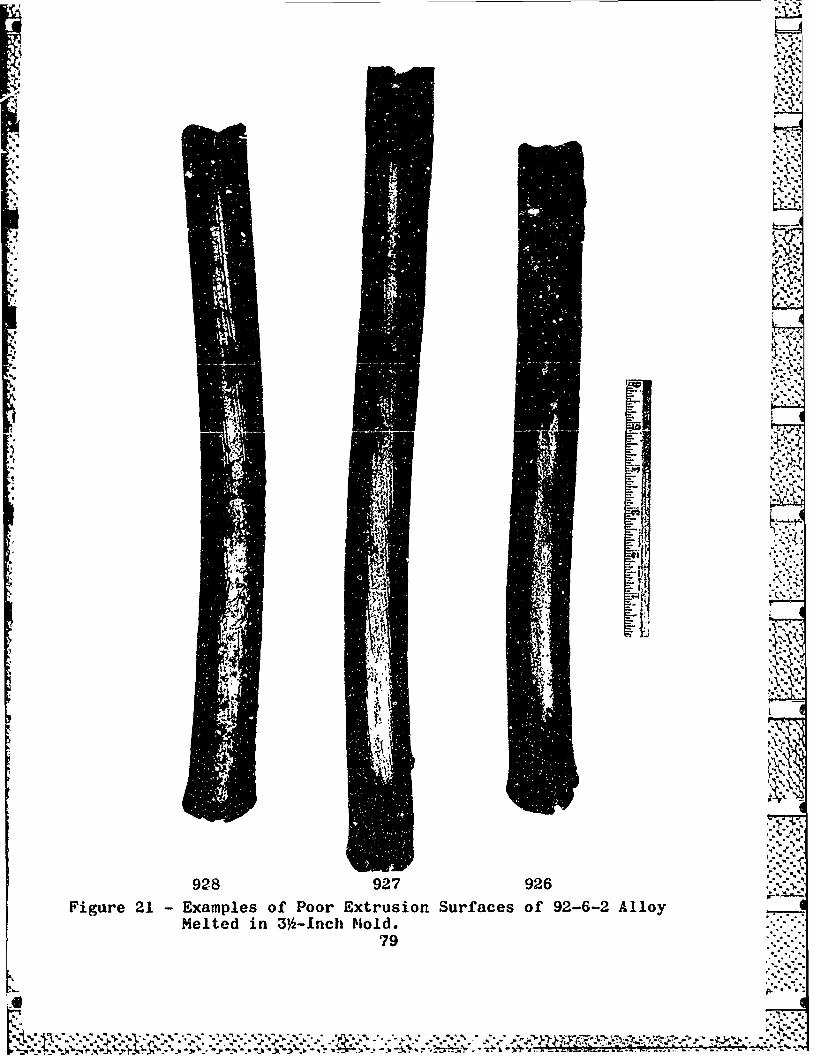
Ii~L '~
-~ -Y
I '4*~1
* I
-r -,*~-. .~;
-p I".
*?' .. ,rL.~.
4
S 4'-.
2AP~A.
q
* *.*-I ~'* N
~'
~%
, -*' *~t
xv.I" "~
~4
**4 -p
'I. ~
928 927 926 * *.'.. .,.,
Figure 21 - Examples of Poor Extrusion Surfaces of 92-6-2 AlloyMelted in 3k-inch Mold.
79
b.. p 4.
Ur~*. p..
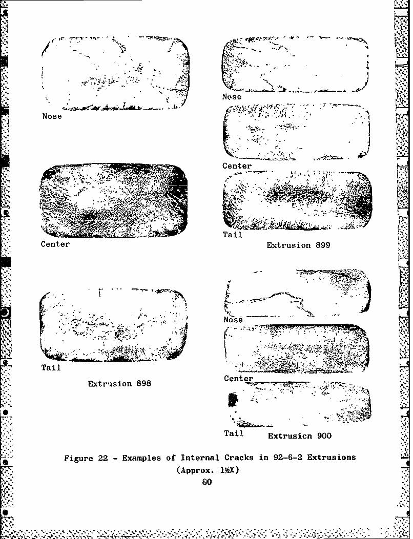
444V
P Nose
"1 Nose
-F Center
Center Extrusion 899
Tail ~'~-___
ExtrsionCenter
Etuin898 i -'
Tail Extrusicn 900
*Figure 22 -Examples of Internal Cracks in 92-6-2 Extrusions
.5(Approx. 1%~X)
SI' s0

-,
I.
V,
4
~ .4 r.4 ~I
V414..,
-i
14
x1.
xV. ~
,~
I.
1010 1009 1008
Figure 2~3 - Examples of Fair Extrusion Surfaces of 92-6-2 Alloy
Melted in 4-inch Mold.
~~1~81L6

z'': W
Z. 0 0L.6+ 0 0 0
u-002 -002WI:'.
"Rad i,/ 6"Rad. ,
LL
AAW 11 L R atioD L ati
2.050 0.825 1.549 A 5:1 1.590 1.167 4:12.050 0.705 1.609 % 6:1 1.428 1.248 5:12.050 0.688 1.628 'A 7:1 1.310 1.307 6:1 a2.050 0.552 1.686 'A 8:1 1.218 1.353 7:12.050 0.355 1.784 "AA 10:1 1.143 1.390 8:1
1.082 1.421 9:1 V',1.028 1.448 10:1
1. Rough Finish required on this surface.2. Angle will hold only at centerline of sides "W". Remainder of
entrance cone to taper smoothly into 36" entrance radius.3. Break all sharp corners.4. Material - SAE H-12 tool steel, H.T. Re 40-44.5. Application of 30-mil Zr02 coating produces indicated ratios.
Figure 24 - Detail of Rectangular and Round Extrusion Dies
82
q %

35----P
.250
.235
.06,1__
2.750.178
1.500-* .179 " '
.063.... .063R
.313 ,+,- .03IR
250 " :
dimensions are in inches
Figure 25 - Specimen for 3000OF Tensile Tests 'N
83
SxnU

-'1
----------
913N 913C
,j'- - " "---- --, :. . 4 . ./"------ -: .. . "- - . ,.,-
915C 915T
'- -" , .7N - > --,,
- -)7
.-.... N. .: .. ¢. .. ,-7
"'" .. -"- * c." . ,- ,'
. -- . - - .. , . . . - - 2* .u-- "_ - --.._
928C 928T
Figure 26 - Microstructures of 92-6-2 Samples from which TensileSamples were Machined.
Electropolished - Murakami's Etch - 250X
84
4 _
I":',. . :: ' .¢.:: . .:" " "; :..: :,"- :..""',2... L ;,)-:--":-.,_ fs;". ', - '.,

-~~~~ -- - - -- - - -
NoeCntrTi
Exrso 898 380F .:
~7
-~- L-,: _NI
'sk-.* .~~~jj
Nos Cete Tai
Nose Center Tail ~ ,
Extrusion 980, 4200O0F, 4.4:1
Figure~~~~~~~~? 27-Mcotucue f9-62Etuin
Elctoplihe Muaam- Etc 25
* 8*'**.

4 r4
-
-~W R. ., ',-
Nose Center TailExtrusion 943, , 400 0 0 4.3:1
Figue 2 Mirosrucuresof 2-62 EtruionsShoingBaningElectroolished Murakam'.1 Ech'
86.N-

'Al
*20%40
60% 80%A
Figure 29 -Effect of Percent Reduction on Recrystallized Grain Sizeof Forged W+0.6Cb Alloy. Wedge from Extrusion 993 wasAnnealed at 3400OF for I Hour, Forged at 28000F, and thenAnnealed at 3000OF for 1 Hour.
Electropolished -Murakami's Etch -50X
87

260O 2800OF-- *
- -~ *1 TIC
3000 F 200OF
3400OF3600O
Figur 30 Rersalzt eairofEtue 262Alywe
Sujce toAnaigfr1Hu a h niae eperatres Saple frm Etruion899Elcrplse urkm' th 2O

IF. 220O
1200OF
.989

4oi
4
759 (Extruded and Recrystallized)
763 (Extruded, Forged, and Recrystallized)
*992 (Extruded, Forged, and Recrystallized)
Figure 32 -W+0.6Cb Sample Failures Encountered During Early RollingStages.
90

Swaged from 1.22" to .940"(41%) @ 2700OF
'*~ -~ Annealed 1 hour @ 34000F
Swaged from .940" to .610"(58%) @ 27000F
974, Annealed, Swaged 58%
Swaged from 1.13" to .840"(45%) @ 2400OF
Annealed 1 hour @ 3200OF
-- Swaged from .840" to .687"(35%) @ 22000F.
*994, Annealed, Swaged 35%
Swaged from 1.19" to .940"1(39%) @ 27000F
__ Annealed I hour @32000F
*- Swaged from .940" to .610"-~ (58%) @ 2400OF
-. i S
995, Annealed, Swaged 58% -
- - ~~-;r- -- Swaged from 1.20" to .940"1- -~ (39%) @ 2700OF
~ Annealed 1 hour @ 3200OF~ 22~- -- ~-'Swaged from .940" to .610"
.-7 (5% @ ~ ~ 2700OF
997, Annealed, Swaged 58% SAMPLE HISTORIESFigure 33 -Annealed and Swaged W+0.6Cb Microstructures. Tensile
Results are shown in Table 17, and Extrusion Structuresof 994, 995, and 997 are shown in Figures 10 and 16.
Electropolished - Murakami's Etch - OX91

d~ -,
4 - ~------'--,--.------- -- ~~0.~~~'~
~ -- ,0~*
-~ ~ -
*0~~ - q
-' 40 .~
~* # *~aej
.-.- ~-
?~- & 440 *
* ~ - -~~*; .. t...~ S -- -,
<-~40-~A3..u a.
4' 0
0~
* ~'' Aa~ -. -
- .4' 4 Cu.-a. * *,
~ 1~-'~ 4- ~- * * a -. 4,
-~ - - .- ~-~.4- .
a~M5.~~~*. - - t~. *.'L~
-~ -4.*~.iCy~
- - a*a..... 'N. .4 -
Extrusion 1028, Swaged to .937"
-i
"S'a
S-v
-'4 .4.
94
4*54
-9
4~040~045
.5. "I
* C4~. 4,
54414
Extrusion 1043, Swaged to .937"
a'
Figure 34 - Extruded and Swaged 92-6-2 Microstructures.-.5
.6 Electropolished - Murakami's Etch - 50X
92
S
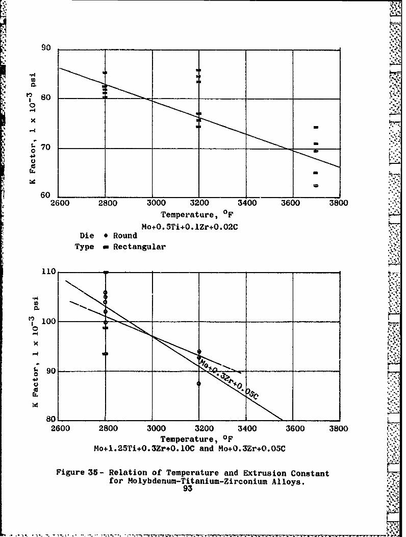
80 :"
" "a,-?
70"
60 -2600 2800 3000 3200 3400 3600 3800 [i,
Temperature, OFo+0.5Ti+O.1Zr+O. 02C
Die •Round"'
Type =Rectangular...
110 Y
100
90
80
2600 2800 3000 3200 3400 3600 3800 ."+Temperature, OF
o+1. 25Ti+0.3Zr+O./0- and o+O.3r+0.05C"'
Figure 35- Relation of Temperature and Extrusion Constant
for Molybdenum-Titanium-Zirconium Alloys.93

120S
o~
* 110
0z.
0S4 41MTh-~ 03
9020260 2800 300 ( 3200 3400 3600 3800
Temeraure 0F (10) WADD 60-418(11)
Die *Round
Type *Rectangular
o Wv
0 0
0
0U
*3000 3200 3400 3600 3800 4000 4200
Temperature, 0F
Figure 36 -Relation of Temperature and Extrusion Constantfor Molybdenum-Co umbium and Molybdenum-TungstenAlloys, and Molybdenum Tubing.
94

Cv t
I'.-%14I-
- / /00
444
4E-
'V Cq
t °toU) 0 .17-
"- 'I ±-
. C -9-I
0 / /)
4 0 0 O
pa-4-
" K Factor, psi x 10- 3
Figure 37 -Relation of Temperature and ExtrusionConstant for Mo-Base Alloys (Summary).
95.,
.=v -r~ .' -- .' ," .' .'""%'tt" ." .....''''' E , ' -':., ,j .% ,-,.-". ",*.""• " *. 0"e.!/""# " ."/i-, -+ -, .,.,,.V, -%,",T" " " €" "0*." .

00
rq x.
S a
0 r-
ou
0d m
I P4
40
96)

120
110
100
0
90
0
* I%7
~80
W+0. lHf+0.002C K
70 __ ____ Wi-.05Zr+0.001C@W+3No+0. lHf+0.002C7
60 6 W+3Mo+0.O5Zr+0.003C
IOfot jacketed billet
6013000 3200 3400 3600 3800 4000 4200
Temperature, OF'*
Figure 39 -Relation of Temperature and Extrusion Constant forHigh-Strength Tungsten-Base Alloy Billets Producedby Climax Molybdenum Co.
97

O C
110
eCU-. t. I
*'*4 100
70
60
OU FTepraue
* u)(100 uc. 0-1C_ -_ Clma MoydnuoAr at
Figue 4 Reltio ofTemperature an xrsonCntn
fo UGnaloe Elngctrc (Sinteera Supies
UC -UivrslCylps(AcCat

.. . y o/oO°:.°...
> 4 • i.i.
/ ,,; ,,4 -. ,,,
'4 o // . "..,.
/ .4/.,.
* / ,, /
" /to
4. /t /."-I
0000
0 *I
0I
,*., -?
,.* ,- - 4 p,.'0
toO
0
004 to
W0
r-4 0'/ 00 1 5 N to to
K Facor I $144s
Figure 41 -Relation of Temperature and Extrusion --Constant for W-Base Alloys (Summary).
99