Embed Size (px)
Citation preview

Contact your local Twin Disc representative for engineering specifications. Specifications subject to change without prior notice in the interest of continual product improvement.
ASD 8Twin Disc Surface Drives
ASD 8ARNESON SURFACE DRIVE
ACCESSORIESAnode KitCylinder position indicator kits with gaugeHydraulic power steering system Gearbox adapterDriveline (cardan shaft)Companion (input) flangeTie-bar (mechanical or hydraulic – for multiple engine vessels)Inboard cylinder mounting kitPropeller
TECHNICAL DATA
ASD08B1L ASD08B3LDROP DISTANCE 10 INCH 16 INCH
Reduction Ratio/ Maximum Input Torque
1.00:11200 ft-lbs
1.00:1 / 1200 ft-lbs
1.32:1 / 909 ft-lbs
1.42:1 / 845 ft-lbs
1.53:1 / 785 ft-lbs
Unit Weight 285 lbsC458 lbs C485 lbs
B610 lbs B680 lbs
Overall Length 42 in 54 in
Nominal Shaft Diameter 2 in 2 in
Steering Angle Degree 40 degrees 40 degrees
Trim Angle Degree 15 degrees 15 degrees
DESCRIPTIONBRONZE IN-LINE (ASD08B1L)ALUMINUM-BRONZE DROP-CENTER (ASD08B3L)
Bronze thrust assemblyBronze (B) or aluminum (C) drop box (drop-center drives only)Internal lube oil reservoir Steering cylinder with external hoses and fittingsTrim cylinder with external hoses and fittings Standard (or optional longer) finStandard 25-tooth (or optional 26-tooth) splined propeller shaft Installation manual, owners manual and drive ball wrench (one per ship set)

Twin Disc, Incorporated reminds users of these products that their safe operation depends on use in compliance with engineering information provided in our catalog. Users are also reminded that safe operation depends on proper installation, operation and routine maintenance and inspection under prevailing conditions. It is the responsibility of users (and not Twin Disc, Incorporated) to provide and install guards or safety devices which may be required by recognized safety standards or by the Occupational Safety and Health Act of 1970 and its subsequent provisions. TD-Bulletin-ASD8
© 2009, Twin Disc, IncorporatedPrinted in the USA – 04/2009
Twin Disc, IncorporatedRacine, Wisconsin 53403 USA
Phone +1-262-638-4000Fax +1-262-638-4482
www.twindisc.com
ASD 8 DROP-CENTER & IN-LINE SURFACE DRIVE SCHEMATICS
2.28
2.62
18.64
12.308.75
Steering Cylinder
TOP VIEW
INPUT SHAFT DETAIL
8.00
2.00.88
COMPANIONFLANGE
3.501.87
4.13
2.28
20.49
35.57
18.9020.88
33.38
42.20
6°±1°
Trim Cylinder
SIDE VIEW(6° Transom Angle)
END VIEW(Dimensions are Parallel with Transom)
R 6.15
4.50
19.37
23° DEADRISESHOWN
(FOR 6° TRANSOM ONLY)
20.09
5.70
36°
Standard Fin – 12.00Optional Long Fin – 15.00
TOP VIEW
SIDE VIEW
END VIEW
0-19° STD CYL=32.81 IN.H.D. CYL=34.64 IN.
20-31° STD CYL=29.05 IN.H.D. CYL=29.50 IN.BOTH CYLS=26.93 IN.
INTERFACE DETAIL
31°
{{{
35.57
Standard Fin – 12.00Optional Long Fin – 15.00 8.25
8.93
10.19
17.7129.8131.96
44.46
8.80
2.62
27.25 MAX.22.75 MIN.
Steering Cylinder
Trim Cylinder
SHAFT SPLINE DATA
2.004.25
4.80 TRANSOM
COMPANIONFLANGE
31°
DROP-CENTER
IN-LINE

Contact your local Twin Disc representative for engineering specifications. Specifications subject to change without prior notice in the interest of continual product improvement.
ASD 10Twin Disc Surface Drives
ASD 10ARNESON SURFACE DRIVE
ACCESSORIESAnode kitCylinder position indicator kits with gaugeHydraulic power steering systemGearbox adapterDriveline (cardan shaft)Companion (input) flangeTie-bar (mechanical or hydraulic – for multiple engine vessels)Inboard cylinder mounting kitPropeller
DESCRIPTIONBRONZE IN-LINE (ASD10BIL) ALUMINUM OR BRONZE DROP-CENTER (ASD10B1S)
Bronze thrust assemblyBronze (B) or aluminum (C) drop box (drop-center drives only)Internal lube oil reservoirSteering cylinder with external hoses and fittingsTrim cylinder with external hoses and fittings Installation manual, owners manual and drive ball wrench (one per ship set)
TECHNICAL DATA
ASD10B1L ASD10B3S
Reduction RatioIn-Line 10 in – 16 in
1.00:1 1.00:1
Maximum Input Torque 2000 ft-lbs 1500 ft-lbs
Unit Weight 417 lbs
10 in: C560 lbs
10 in: B750 lbs
16 in: C600 lbs
16 in: B820 lbs
Overall Length 53 in 63 in
Nominal Shaft Diameter 2.5 in 2.5 in
Steering Angle Degree 40 degrees 40 degrees
Trim Angle Degree 15 degrees 15 degrees
Twin Disc, Incorporated reminds users of these products that their safe operation depends on use in compliance with engineering information provided in our catalog. Users are also reminded that safe operation depends on proper installation, operation and routine maintenance and inspection under prevailing conditions. It is the responsibility of users (and not Twin Disc, Incorporated) to provide and install guards or safety devices which may be required by recognized safety standards or by the Occupational Safety and Health Act of 1970 and its subsequent provisions. TD-Bulletin-ASD10
© 2009, Twin Disc, IncorporatedPrinted in the USA – 04/2009
Twin Disc, IncorporatedRacine, Wisconsin 53403 USA
Phone +1-262-638-4000Fax +1-262-638-4482
www.twindisc.com
ASD 10 IN-LINE SURFACE DRIVE SCHEMATICS
16.95
2.30
2.50
13.75
TOP VIEW
Steering Cylinder
Trim Cylinder
SIDE VIEW(6° Transom Angle)
21.81
6.64
2.75
10.54
8.5222.6624.75
41.8952.75
6°±1°
14.50
END VIEW(Dimensions are Parallel with Transom)
INPUT SHAFT DETAIL
1.99
1.00 2.0010.36
6.00
21.08
17.81
5.506.87
7.836.88 R
45°
23° DEADRISESHOWN(FOR 6° TRANSOM ONLY)
CONTACT TWIN DISC FOR DROP-CENTER SURFACE DRIVE SCHEMATICS
Contact your local Twin Disc representative for engineering specifications. Specifications subject to change without prior notice in the interest of continual product improvement.
ASD 11Twin Disc Surface Drives
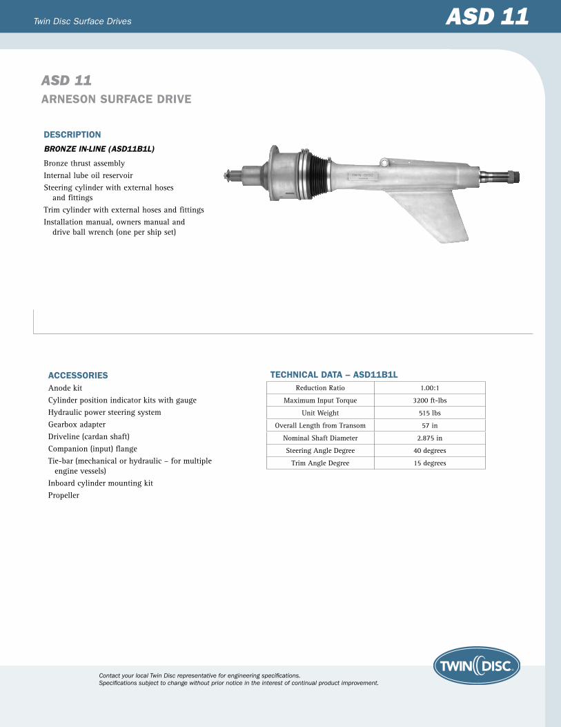
ASD 11ARNESON SURFACE DRIVE
ACCESSORIESAnode kitCylinder position indicator kits with gaugeHydraulic power steering systemGearbox adapterDriveline (cardan shaft)Companion (input) flangeTie-bar (mechanical or hydraulic – for multiple engine vessels)Inboard cylinder mounting kitPropeller
TECHNICAL DATA – ASD11B1LReduction Ratio 1.00:1
Maximum Input Torque 3200 ft-lbs
Unit Weight 515 lbs
Overall Length from Transom 57 in
Nominal Shaft Diameter 2.875 in
Steering Angle Degree 40 degrees
Trim Angle Degree 15 degrees
DESCRIPTION
BRONZE IN-LINE (ASD11B1L)
Bronze thrust assemblyInternal lube oil reservoirSteering cylinder with external hoses and fittingsTrim cylinder with external hoses and fittings Installation manual, owners manual and drive ball wrench (one per ship set)

Twin Disc, Incorporated reminds users of these products that their safe operation depends on use in compliance with engineering information provided in our catalog. Users are also reminded that safe operation depends on proper installation, operation and routine maintenance and inspection under prevailing conditions. It is the responsibility of users (and not Twin Disc, Incorporated) to provide and install guards or safety devices which may be required by recognized safety standards or by the Occupational Safety and Health Act of 1970 and its subsequent provisions. TD-Bulletin-ASD11
© 2009, Twin Disc, IncorporatedPrinted in the USA – 04/2009
Twin Disc, IncorporatedRacine, Wisconsin 53403 USA
Phone +1-262-638-4000Fax +1-262-638-4482
www.twindisc.com
ASD 11 IN-LINE SURFACE DRIVE SCHEMATICS
TOP VIEW
SIDE VIEW(6° Transom Angle)
INPUT SHAFT DETAIL
Steering Cylinder
21.3925.34
2.64
Trim Cylinder29.47
10.31
6.502.58
1.18
4.93
25.60
7.06
6.64
6°
END VIEW(Dimensions are Parallel with Transom)
23.35
6.88 R
43.5°
21° DEADRISESHOWN
19.14
5.65
6.59(FOR 6° TRANSOM ONLY)
6.05
21.39
Contact your local Twin Disc representative for engineering specifications. Specifications subject to change without prior notice in the interest of continual product improvement.
ASD 12Twin Disc Surface Drives
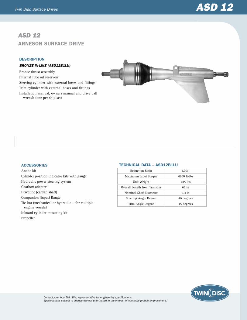
ASD 12ARNESON SURFACE DRIVE
ACCESSORIESAnode kitCylinder position indicator kits with gaugeHydraulic power steering systemGearbox adapterDriveline (cardan shaft)Companion (input) flangeTie-bar (mechanical or hydraulic – for multiple engine vessels)Inboard cylinder mounting kitPropeller
DESCRIPTION
BRONZE IN-LINE (ASD12B1LU)
Bronze thrust assemblyInternal lube oil reservoirSteering cylinder with external hoses and fittingsTrim cylinder with external hoses and fittings Installation manual, owners manual and drive ball wrench (one per ship set)
TECHNICAL DATA – ASD12B1LUReduction Ratio 1.00:1
Maximum Input Torque 4800 ft-lbs
Unit Weight 785 lbs
Overall Length from Transom 63 in
Nominal Shaft Diameter 3.3 in
Steering Angle Degree 40 degrees
Trim Angle Degree 15 degrees
Twin Disc, Incorporated reminds users of these products that their safe operation depends on use in compliance with engineering information provided in our catalog. Users are also reminded that safe operation depends on proper installation, operation and routine maintenance and inspection under prevailing conditions. It is the responsibility of users (and not Twin Disc, Incorporated) to provide and install guards or safety devices which may be required by recognized safety standards or by the Occupational Safety and Health Act of 1970 and its subsequent provisions. TD-Bulletin-ASD12
© 2009, Twin Disc, IncorporatedPrinted in the USA – 04/2009
Twin Disc, IncorporatedRacine, Wisconsin 53403 USA
Phone +1-262-638-4000Fax +1-262-638-4482
www.twindisc.com
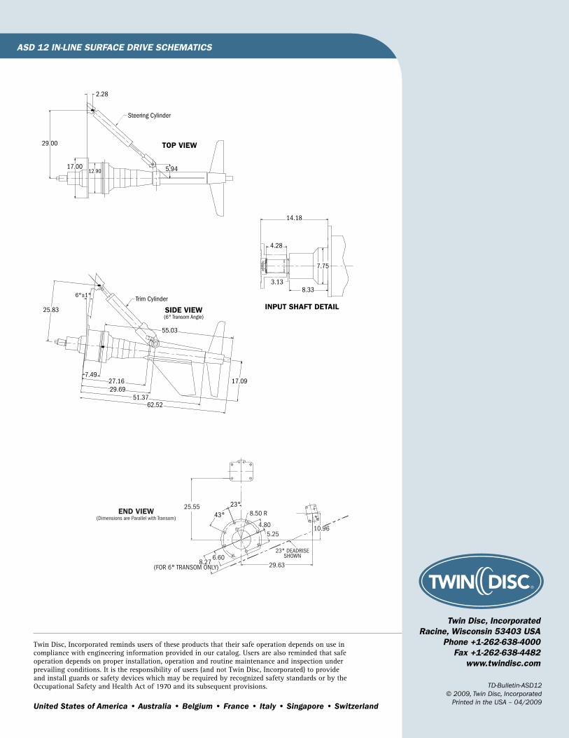
ASD 12 IN-LINE SURFACE DRIVE SCHEMATICS
SIDE VIEW(6° Transom Angle)
INPUT SHAFT DETAIL
TOP VIEW
Trim Cylinder6°±1°
25.83
7.4927.1629.69
51.3762.52
17.09
55.03
2.28
29.00
17.0012.90 5.94
Steering Cylinder
14.18
4.28
3.138.33
7.75
END VIEW(Dimensions are Parallel with Transom)
25.55
6.608.27
(FOR 6° TRANSOM ONLY)
23° DEADRISESHOWN
8.50 R
4.80
29.63
5.25
23°
43°
10.96

Contact your local Twin Disc representative for engineering specifications. Specifications subject to change without prior notice in the interest of continual product improvement.
ASD 14Twin Disc Surface Drives
ASD 14ARNESON SURFACE DRIVE
ACCESSORIESAnode kitCylinder position indicator kits with gaugeHydraulic power steering systemGearbox adapterDriveline (cardan shaft)Companion (input) flangeTie-bar (mechanical or hydraulic – for multiple engine vessels)Inboard cylinder mounting kitPropeller
DESCRIPTION
BRONZE IN-LINE (ASD14BIL)
Bronze thrust assemblyInternal lube oil reservoirSteering cylinder with external hoses and fittingsTrim cylinder with external hoses and fittings Standard (or optional longer) finInstallation manual, owners manual and drive ball wrench (one per ship set)
TECHNICAL DATA – ASD14BILReduction Ratio 1.00:1
Maximum Input Torque 8000 ft-lbs
Unit Weight 1135 lbs
Overall Length from Transom 71 in
Nominal Shaft Diameter 3.5 in
Steering Angle Degree 40 degrees
Trim Angle Degree 15 degrees

Twin Disc, Incorporated reminds users of these products that their safe operation depends on use in compliance with engineering information provided in our catalog. Users are also reminded that safe operation depends on proper installation, operation and routine maintenance and inspection under prevailing conditions. It is the responsibility of users (and not Twin Disc, Incorporated) to provide and install guards or safety devices which may be required by recognized safety standards or by the Occupational Safety and Health Act of 1970 and its subsequent provisions. TD-Bulletin-ASD14
© 2009, Twin Disc, IncorporatedPrinted in the USA – 04/2009
Twin Disc, IncorporatedRacine, Wisconsin 53403 USA
Phone +1-262-638-4000Fax +1-262-638-4482
www.twindisc.com
ASD 14 IN-LINE SURFACE DRIVE SCHEMATICS
TOP VIEW
INPUT SHAFT DETAIL
SIDE VIEW(6° Transom Angle)
18.94
14.81
37.9834.58
2.28
5.94
Trim Cylinder
3.11
34.10
27.26
9.59
8.9911.62
33.6435.94
57.8271.17
26.60
7.44
9.71FOR 6° TRANSOM ONLY) 35.49
9.39
38.10
30°30° 20° DEADRISE
SHOWN
23°9.47 R
6°±1
3.7515.19
15.6619.768.57
3.22 8.44
1.50
END VIEW(Dimensions are Parallel with Transom)
BOTTOM HULL
Standard Fin – 18.00Optional Long Fin – 21.00

Contact your local Twin Disc representative for engineering specifications. Specifications subject to change without prior notice in the interest of continual product improvement.
ASD 15Twin Disc Surface Drives
ASD 15ARNESON SURFACE DRIVE
ACCESSORIESAnode kitCylinder position indicator kits with gaugeHydraulic power steering systemGearbox adapterDriveline (cardan shaft)Companion (input) flangeTie-bar (mechanical or hydraulic – for multiple engine vessels)Propeller
TECHNICAL DATA
ASD15A1S ASD15A1LReduction Ratio 1.00:1 1.00:1
Maximum Input Torque 11,500 ft-lbs 13,500 ft-lbs
Unit Weight 1,500 lbs 1,540 lbs
Overall Length from Transom 78 in 78 in
Nominal Shaft Diameter 4.5 in 4.5 in
Steering Angle Degree 36 degrees 36 degrees
Trim Angle Degree 15 degrees 15 degrees
DESCRIPTION
ALUMINUM IN-LINE (ASD15A1S AND ASD15A1L)
Aluminum thrust assemblyInternal lube oil reservoirSteering cylinder with external hoses and fittingsTrim cylinder with external hoses and fittings Installation manual, owners manual and drive ball wrench (one per ship set)

Twin Disc, Incorporated reminds users of these products that their safe operation depends on use in compliance with engineering information provided in our catalog. Users are also reminded that safe operation depends on proper installation, operation and routine maintenance and inspection under prevailing conditions. It is the responsibility of users (and not Twin Disc, Incorporated) to provide and install guards or safety devices which may be required by recognized safety standards or by the Occupational Safety and Health Act of 1970 and its subsequent provisions. TD-Bulletin-ASD15
© 2009, Twin Disc, IncorporatedPrinted in the USA – 04/2009
Twin Disc, IncorporatedRacine, Wisconsin 53403 USA
Phone +1-262-638-4000Fax +1-262-638-4482
www.twindisc.com
ASD 15 IN-LINE SURFACE DRIVE SCHEMATICS
TOP VIEW
Steering Cylinder
INPUT SHAFT DETAIL
SIDE VIEW(6° Transom Angle)
END VIEW
Trim Cylinder
975.74
540.00
866.14
304.06
397.50 361.74248.84
888.161552.66
1986.70
866.15
314.16304.06
220.00
306.00
15°
2°
22°
533.89
6°
142.001737.86
Transom
848.00215.00
200.00440.00
584.
00
BOTTOM HULL
975.74
84.06

Contact your local Twin Disc representative for engineering specifications. Specifications subject to change without prior notice in the interest of continual product improvement.
ASD 16Twin Disc Surface Drives
ASD 16ARNESON SURFACE DRIVE
ACCESSORIESAnode kitCylinder position gaugesHydraulic power steering systemGearbox adapterDriveline (cardan shaft)Companion (input) flangeTie-bar (mechanical or hydraulic – for multiple engine vessels)Propeller
DESCRIPTION
ALUMINUM IN-LINE (ASD16A1LU)
Aluminum thrust assemblyInternal lube oil reservoirSteering cylinder (electronic feedback) with external hoses and fittingsTrim cylinder (electronic feedback) with external hoses and fittings Installation manual, owners manual and drive ball wrench (one per ship set)
TECHNICAL DATA – ASD16A1LUReduction Ratio 1.00:1
Maximum Input Torque 16,500 ft-lbs
Unit Weight 1,985 lbs
Overall Length from Transom 87 in
Nominal Shaft Diameter 4.5 in
Steering Angle Degree 36 degrees
Trim Angle Degree 15 degrees

Twin Disc, Incorporated reminds users of these products that their safe operation depends on use in compliance with engineering information provided in our catalog. Users are also reminded that safe operation depends on proper installation, operation and routine maintenance and inspection under prevailing conditions. It is the responsibility of users (and not Twin Disc, Incorporated) to provide and install guards or safety devices which may be required by recognized safety standards or by the Occupational Safety and Health Act of 1970 and its subsequent provisions. TD-Bulletin-ASD16
© 2009, Twin Disc, IncorporatedPrinted in the USA – 04/2009
Twin Disc, IncorporatedRacine, Wisconsin 53403 USA
Phone +1-262-638-4000Fax +1-262-638-4482
www.twindisc.com
ASD 16 IN-LINE SURFACE DRIVE SCHEMATICS
TOP VIEW
Steering Cylinder
INPUT SHAFT DETAIL
SIDE VIEW(6° Transom Angle)
Trim Cylinder36.93
18.2910.8116.08
38.81
21.00
67.6886.54
22.13
6.18
75.2623.1764.27
46.87
23.00 8.83
3.83
4.759.50 12.75
18.2918.92
6°
END VIEW
43.3713.199.62
38.78
13.21
BOTTOM HULL22°
20°