Embed Size (px)
Citation preview
All Rights Reserved.E202331---04/09
ASCO ValvesEASCO Valve, Inc.R 50 Hanover Road, Florham Park, New Jersey 07932 www.ascovalve.com
Operation & Maintenance Guide
I&M No. V9512R6
THIS DOCUMENT CONTROLLEDBY RCS Ex CERTIFICATION
Page 2 of 25 I&M No.V9512R6
EASCO Valve, Inc.R 50 Hanover Road, Florham Park, New Jersey 07932 www.ascovalve.com
I&M No.V9512R6Redundant Control System
Operation & Maintenance Guide
Table of Contents
Product Description & Specifications 3 --- 5
Section 1 --- Normally Closed
Section 2 --- Normally Open
Section 3 --- Double Acting
Section 4
1. General Operation
Installation
2. Testing and Maintenance
1. General Operation2. Testing and Maintenance
1. General Operation2. Testing and Maintenance
1. Functional Test Certification2. Spare Parts
9
911
7
12
1214
15
15
18
17
18
18
181819
3. Packaging4. Limited Warranty
21RCS---R Wiring Diagram (A)RCS---L Wiring Diagram (B)
5. Tools Required for Routine Service
23
5 --- 6Nameplate Information
24RCS N.C. Piping Diagrams25RCS N.O. Piping Diagrams
Page 3 of 25I&M No.V9512R6
EASCO Valve, Inc.R 50 Hanover Road, Florham Park, New Jersey 07932 www.ascovalve.com
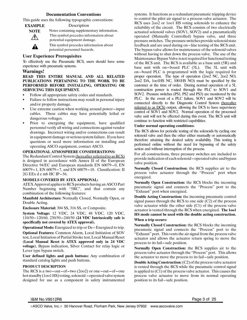
Documentation ConventionsThis guide uses the following typographic conventions:EXAMPLE Description
Notes containing supplementary information.NOTEThis symbol precedes information aboutpotential equipment damage.This symbol precedes information aboutpotential personnel hazards.
User Experience PrerequisitesTo effectively use the Pneumatic RCS, users should have someexperience with pneumatic systems.Warnings!READ THIS ENTIRE MANUAL AND ALL RELATEDPUBLICATIONS PERTAINING TO THE WORK TO BEPERFORMED BEFORE INSTALLING, OPERATING ORSERVICING THIS EQUIPMENT.S Follow all appropriate safety codes and standards.S Failure to follow instructions may result in personal injuryand/or property damage.
S Use extreme caution when working around power---inputcables. These cables may have potentially lethal ordangerous voltages.
S Prior to energizing the equipment, have qualifiedpersonnel verify all wiring and connections against vendordrawings. Incorrect wiring and/or connections can resultin equipment damageor serious system failure. If youhavequestions or need more information on installing andoperating ASCO equipment, contact ASCO.
OPERATIONAL ATMOSPHERE CONSIDERATIONS:TheRedundant Control System (hereafter referred to asRCS)is designed in accordance with Annex II of the EuropeanDirective 94/EC and European standards EN 60079---0, EN60079---1, EN 60079---7, and EN 60079---18. Classification: II2G EEx d e mb IIC IP---56.MODELS COVERED BY ATEX APPROVAL:ATEXApproval applies toRCSproducts having anASCOPartNumber beginning with “5RC”, and that contain anycombination of the following features:Manifold Architecture: Normally Closed, Normally Open, orDouble Acting.Enclosure Material: 304 SS, 316 SS, or Composite.System Voltage: 12 VDC, 24 VDC, 48 VDC, 120 VDC,110/50---120/60, 230/50---240/50 (24 VDC Intrinsically safe isspecifically not covered by ATEX approval).OperationalMode:Energized to trip orDe---Energized to trip.Optional Features: Common Alarm, Local Initiation of SOVtest, Local Initiation of Partial Stroke test, LocalManualReset(Local Manual Reset is ATEX approved only in 24 VDCvoltage), Bypass indication, Silver Contact for relay logic orLever type bypass switch.User defined lights and push buttons: Any combination ofstandard catalog lights and push buttons.
PRODUCT DESCRIPTIONThe RCS is a two---out---of---two (2oo2) or one---out---of---onehot standby (1oo1HS)voting, solenoid ---operated valve systemdesigned for use as a component in safety instrumented
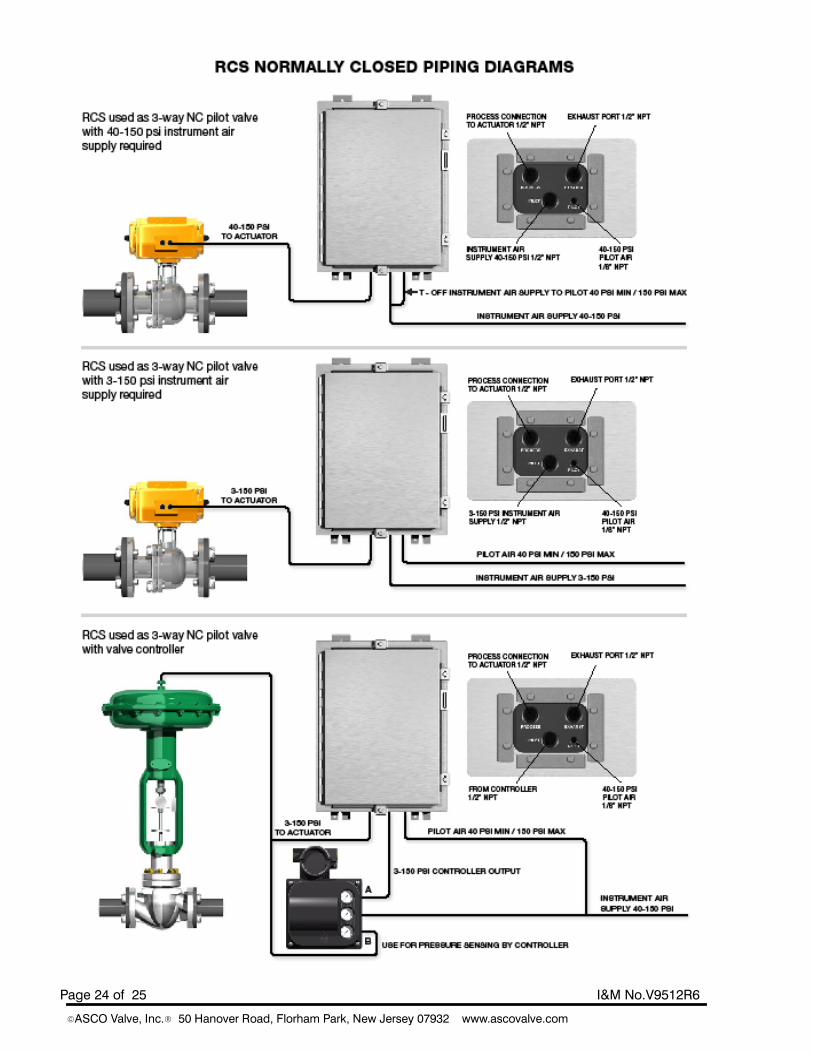
systems. It functions as a redundant pneumatic tripping deviceto control the pilot air signal to a process valve actuator. TheRCS uses 2oo2 or 1oo1 HS voting solenoids to enhance thereliability of the circuit. The RCS consists of two electricallyactuated solenoid valves (SOV1, SOV2) and a pneumaticallyoperated (Manually Controlled) bypass valve, and threepressure switches. Thepressure switchesprovide solenoid statefeedback and are used during on---line testing of the RCS unit.The bypass valve allows for maintenance of the solenoid valveswithout having to shut down the process valve. The use of theMaintenanceBypassValve isnot required for functional testingof the RCS unit. The RCS is available as a base unit (5R) andbase unit with on---board PLC (5L). The 5L unit withon---board PLC is programmed with the logic required forproper operation. The type of operation (2oo2 NC, 2oo2 NO,2oo2 DA, 1oo1HS NC, 1001HS NO) must be specified by thecustomer at the time of order. During normal operation of a 5Lconstruction power is routed through the PLC to SOV1 andSOV2. Pressure switches (PS1, PS2 and PS3) are monitored by thePLC. In the event of a PLC failure, SOV1 and SOV2 will beconnected directly to the Diagnostic Control System (hereafterreferred to as DCS) output, allowing the DCS to have supervisorycontrol of SOV1 and SOV2. Normal operation of the processedvalve unit will not be effected during this event. The RCS unit willcontinue to function with restricted capabilities.Under normal operating conditions:The RCS allows for periodic testing of the solenoids by cycling onesolenoid valve and then the other either manually or automaticallytherefore attaining the desired safety availability. This testing isperformed online without the need for bypassing of the safetyaction and without interruption of the process.For all constructions, three pressure switches are included toprovide indicationof each solenoid---operatedvalve andbypassvalve position.Normally Closed Construction: the RCS supplies air to theprocess valve actuator through the “Process” port whenenergized.Normally Open Construction: the RCS blocks the incomingpneumatic signal and connects the “Process” port to the“Exhaust” port when energized.Double Acting Construction: the incoming pneumatic controlsignal passes through the RCS to one side (C2) of the processvalve actuator while the other side (C1) of the process valveactuator is vented through the RCS when energized. The 1oo1HS mode cannot be used with the double acting construction.When a trip occurs:Normally Closed Construction: the RCS blocks the incomingpneumatic signal and connects the “Process” port to the“Exhaust” port. This vents the air signal from the process valveactuator and allows the actuator return spring to move theprocess to its fail---safe position.Normally Open Construction: the RCS supplies air to theprocess valve actuator through the “Process” port. This allowsthe actuator to move the process to its fail---safe position.Double ActingConstruction: (C2)of the process valve actuatoris vented through the RCS while the pneumatic control signalis applied to (C1) of the process valve actuator. This causes theprocess valve actuator to move from its normal operatingposition to its fail---safe position.
Page 4 of 25 I&M No.V9512R6
EASCO Valve, Inc.R 50 Hanover Road, Florham Park, New Jersey 07932 www.ascovalve.com
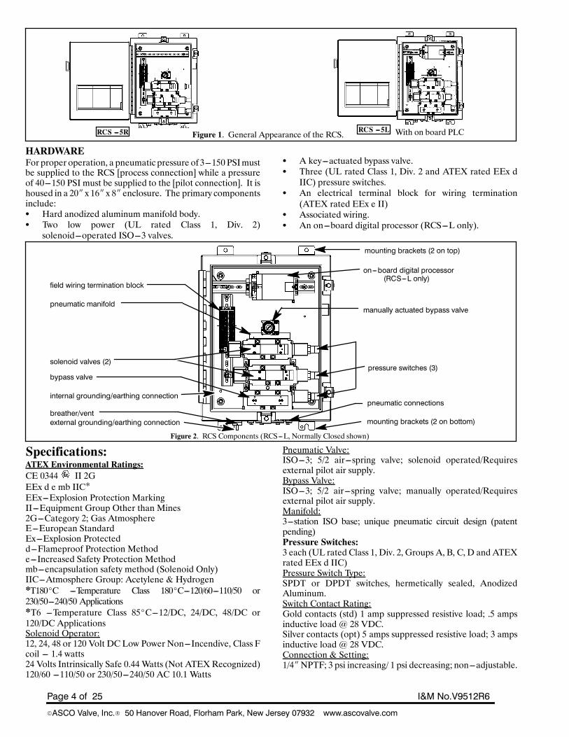
Figure 1. General Appearance of the RCS. With on board PLCRCS ---5R RCS ---5L
HARDWAREFor proper operation, a pneumatic pressure of 3---150 PSImustbe supplied to the RCS [process connection] while a pressureof 40---150 PSI must be supplied to the [pilot connection]. It ishoused in a 20I x 16I x 8I enclosure. The primary componentsinclude:S Hard anodized aluminum manifold body.S Two low power (UL rated Class 1, Div. 2)solenoid---operated ISO---3 valves.
S A key---actuated bypass valve.S Three (UL rated Class 1, Div. 2 and ATEX rated EEx dIIC) pressure switches.
S An electrical terminal block for wiring termination(ATEX rated EEx e II)
S Associated wiring.S An on---board digital processor (RCS---L only).
Figure 2. RCS Components (RCS---L, Normally Closed shown)
mounting brackets (2 on top)
field wiring termination block
pneumatic manifold
solenoid valves (2)
bypass valve
breather/vent
on---board digital processor(RCS---L only)
pressure switches (3)
manually actuated bypass valve
pneumatic connections
mounting brackets (2 on bottom)external grounding/earthing connection
internal grounding/earthing connection
Specifications:ATEX Environmental Ratings:CE 0344 II 2GEEx d e mb IIC*EEx---Explosion Protection MarkingII---Equipment Group Other than Mines2G---Category 2; Gas AtmosphereE---European StandardEx---Explosion Protectedd---Flameproof Protection Methode---Increased Safety Protection Methodmb---encapsulation safety method (Solenoid Only)IIC---Atmosphere Group: Acetylene & Hydrogen*T180_C ---Temperature Class 180_C---120/60---110/50 or230/50---240/50 Applications*T6 ---Temperature Class 85_C---12/DC, 24/DC, 48/DC or120/DC ApplicationsSolenoid Operator:12, 24, 48 or 120 Volt DC Low Power Non---Incendive, Class Fcoil --- 1.4 watts24 Volts Intrinsically Safe 0.44 Watts (Not ATEXRecognized)120/60 ---110/50 or 230/50---240/50 AC 10.1 Watts
Pneumatic Valve:ISO---3; 5/2 air---spring valve; solenoid operated/Requiresexternal pilot air supply.Bypass Valve:ISO---3; 5/2 air---spring valve; manually operated/Requiresexternal pilot air supply.Manifold:3---station ISO base; unique pneumatic circuit design (patentpending)Pressure Switches:3 each (UL rated Class 1, Div. 2, Groups A, B, C, D and ATEXrated EEx d IIC)Pressure Switch Type:SPDT or DPDT switches, hermetically sealed, AnodizedAluminum.Switch Contact Rating:Gold contacts (std) 1 amp suppressed resistive load; .5 ampsinductive load @ 28 VDC.Silver contacts (opt) 5 amps suppressed resistive load; 3 ampsinductive load @ 28 VDC.Connection & Setting:1/4INPTF; 3 psi increasing/ 1 psi decreasing; non---adjustable.
Page 5 of 25I&M No.V9512R6
EASCO Valve, Inc.R 50 Hanover Road, Florham Park, New Jersey 07932 www.ascovalve.com
Electrical:Digital Processor:RCS---L only, 14 inputs, 10 outputs (Class 1, Div.2, Groups A,B, C, D)Pneumatic Connections:Pilot:1/8I NPTFPilot Pressure:40 --- 150 psiInlet & Process:1/2I NPTFExhaust Port:1/2I NPTFProcess Pressure Range:3 psi to 150 psiAir Quality:Instrument air per ANSI/ISA 7.0.01---1996 Particle size ≤ 40microns.Mechanical:Enclosure:Electrical enclosure with hinged door.Size:24Ix 16Ix 8IWeight:Approximately 75 lbs.Materials:Enclosure:Stainless Steel (304 SS, 316 SS) or FiberglassMounting Panel:Painted steel.
Manifold:Anodized aluminum.Valves:Body --- Die---cast Aluminum alloy, Sealing---Nitrile (NBR)and Polyurethane (PUR), Spool and Stainless Steel.Coil:Epoxy encapsulated.Pressure Switches:316 Stainless Steel Wetted SurfacesEnvironmental:Ambient temperature range:Consult panel nameplate to verify.RCS---R = ---40_F to 140_F (---40_C to 60_C)RCS---R with local manual reset option = ---22_F to 140_F(---30_C to 60_C)RCS---L = 32_F to 131_F (0_C to 55_C)RCS---L (extended temp.)= ---10_F to 140_F(---23.3_C to 60_C)Component Certifications:Solenoid12 Volt DC, 24 Volt DC, 120/60---110/50 are UL, FM & CSAcertified for Class 1 & 2, Groups A,B,C,DPressure Switches:CSA approved and UL listed under “Industrial ControlEquipment” ATEX rated EEx d IIC.Approvals:ExidaCertified SIL 3 capable (Standard Normally Open andNormally Closed constructions, see Sil certificate for specialconstructions).
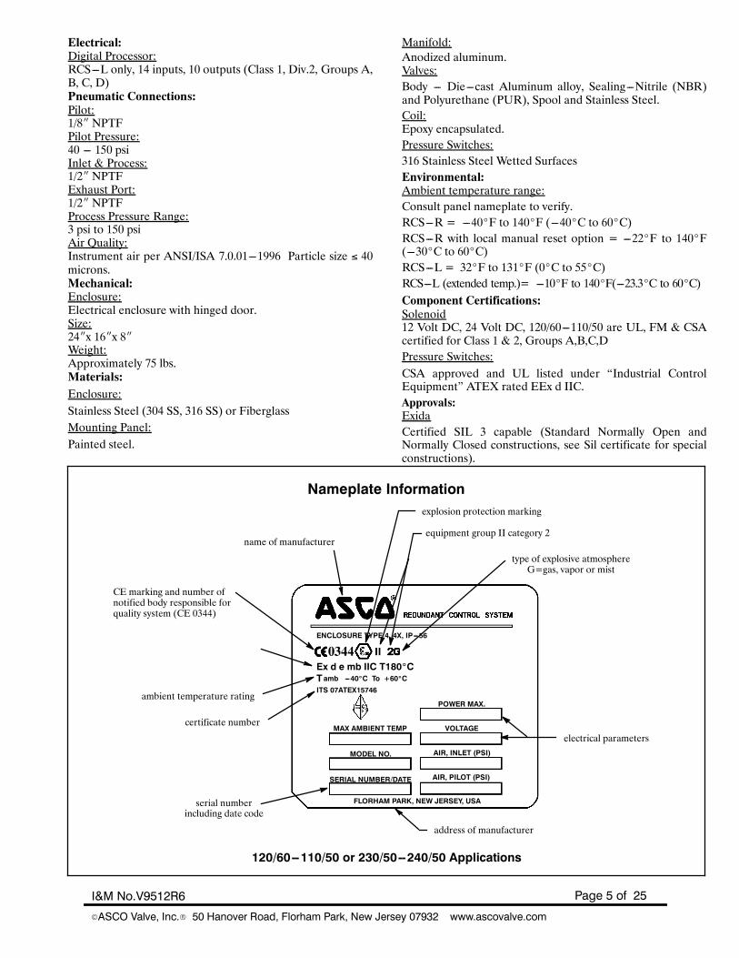
explosion protection marking
equipment group II category 2
certificate number
serial number
address of manufacturer
electrical parameters
ambient temperature rating
type of explosive atmosphereG=gas, vapor or mist
CE marking and number ofnotified body responsible forquality system (CE 0344)
including date code
POWER MAX.
VOLTAGE
AIR, INLET (PSI)
AIR, PILOT (PSI)
MAX AMBIENT TEMP
MODEL NO.
SERIAL NUMBER/DATE
FLORHAM PARK, NEW JERSEY, USA
ENCLOSURE TYPE 4, 4X, IP---56
Ex d e mb IIC T180_C
ITS 07ATEX15746ambT ---40_C To +60_C
120/60--110/50 or 230/50--240/50 Applications
name of manufacturer
Nameplate Information
Page 6 of 25 I&M No.V9512R6
EASCO Valve, Inc.R 50 Hanover Road, Florham Park, New Jersey 07932 www.ascovalve.com
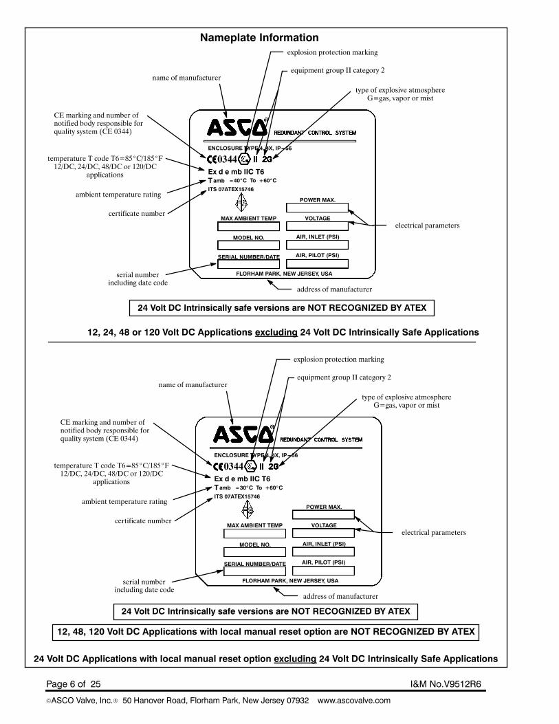
explosion protection marking
name of manufacturerequipment group II category 2
certificate number
serial number
address of manufacturer
electrical parameters
ambient temperature rating
temperature T code T6=85_C/185_F12/DC, 24/DC, 48/DC or 120/DC
applications
type of explosive atmosphereG=gas, vapor or mist
CE marking and number ofnotified body responsible forquality system (CE 0344)
including date code
POWER MAX.
VOLTAGE
AIR, INLET (PSI)
AIR, PILOT (PSI)
MAX AMBIENT TEMP
MODEL NO.
SERIAL NUMBER/DATE
FLORHAM PARK, NEW JERSEY, USA
ENCLOSURE TYPE 4, 4X, IP---56
Ex d e mb IIC T6
ITS 07ATEX15746ambT ---40_C To +60_C
12, 24, 48 or 120 Volt DC Applications excluding 24 Volt DC Intrinsically Safe Applications
Nameplate Information
24 Volt DC Intrinsically safe versions are NOT RECOGNIZED BY ATEX
explosion protection marking
name of manufacturerequipment group II category 2
certificate number
serial number
address of manufacturer
electrical parameters
ambient temperature rating
temperature T code T6=85_C/185_F12/DC, 24/DC, 48/DC or 120/DC
applications
type of explosive atmosphereG=gas, vapor or mist
CE marking and number ofnotified body responsible forquality system (CE 0344)
including date code
POWER MAX.
VOLTAGE
AIR, INLET (PSI)
AIR, PILOT (PSI)
MAX AMBIENT TEMP
MODEL NO.
SERIAL NUMBER/DATE
FLORHAM PARK, NEW JERSEY, USA
ENCLOSURE TYPE 4, 4X, IP---56
Ex d e mb IIC T6
ITS 07ATEX15746ambT ---30_C To +60_C
24 Volt DC Applications with local manual reset option excluding 24 Volt DC Intrinsically Safe Applications
24 Volt DC Intrinsically safe versions are NOT RECOGNIZED BY ATEX
12, 48, 120 Volt DC Applications with local manual reset option are NOT RECOGNIZED BY ATEX
Page 7 of 25I&M No.V9512R6
EASCO Valve, Inc.R 50 Hanover Road, Florham Park, New Jersey 07932 www.ascovalve.com
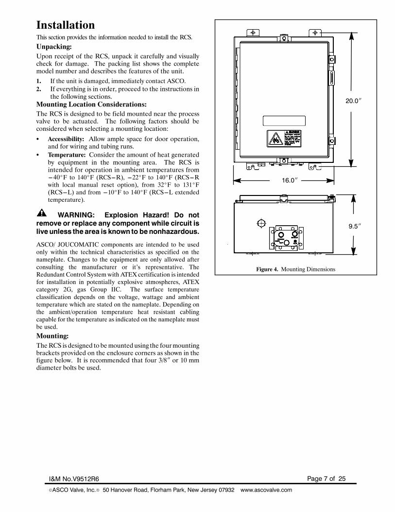
InstallationThis section provides the information needed to install the RCS.Unpacking:Upon receipt of the RCS, unpack it carefully and visuallycheck for damage. The packing list shows the completemodel number and describes the features of the unit.1. If the unit is damaged, immediately contact ASCO.2. If everything is in order, proceed to the instructions in
the following sections.Mounting Location Considerations:The RCS is designed to be field mounted near the processvalve to be actuated. The following factors should beconsidered when selecting a mounting location:
S Accessibility: Allow ample space for door operation,and for wiring and tubing runs.
S Temperature: Consider the amount of heat generatedby equipment in the mounting area. The RCS isintended for operation in ambient temperatures from---40_F to 140_F (RCS---R), ---22_F to 140_F (RCS---Rwith local manual reset option), from 32_F to 131_F(RCS---L) and from ---10_F to 140_F (RCS---L extendedtemperature).
WARNING: Explosion Hazard! Do notremove or replace any component while circuit islive unless the area is known to benonhazardous.
ASCO/ JOUCOMATIC components are intended to be usedonly within the technical characteristics as specified on thenameplate. Changes to the equipment are only allowed afterconsulting the manufacturer or it’s representative. TheRedundant Control Systemwith ATEXcertification is intendedfor installation in potentially explosive atmospheres, ATEXcategory 2G, gas Group IIC. The surface temperatureclassification depends on the voltage, wattage and ambienttemperature which are stated on the nameplate. Depending onthe ambient/operation temperature heat resistant cablingcapable for the temperature as indicated on the nameplate mustbe used.
Mounting:TheRCS is designed to bemounted using the fourmountingbrackets provided on the enclosure corners as shown in thefigure below. It is recommended that four 3/8I or 10 mmdiameter bolts be used.
Figure 4. Mounting Dimensions
9.5I
20.0I
16.0I
Page 8 of 25 I&M No.V9512R6
EASCO Valve, Inc.R 50 Hanover Road, Florham Park, New Jersey 07932 www.ascovalve.com
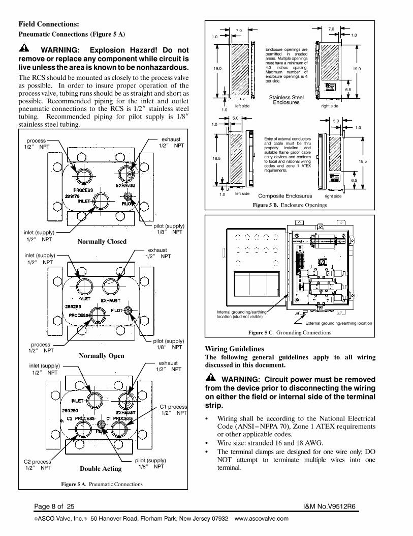
Field Connections:Pneumatic Connections (Figure 5 A)
WARNING: Explosion Hazard! Do notremove or replace any component while circuit islive unless the area is known to benonhazardous.The RCS should be mounted as closely to the process valveas possible. In order to insure proper operation of theprocess valve, tubing runs should be as straight and short aspossible. Recommended piping for the inlet and outletpneumatic connections to the RCS is 1/2I stainless steeltubing. Recommended piping for pilot supply is 1/8Istainless steel tubing.
Figure 5 A. Pneumatic Connections
process1/2I NPT
exhaust1/2I NPT
inlet (supply)1/2I NPT
pilot (supply)1/8I NPT
Normally Closed
Normally Open
Double Acting
inlet (supply)1/2I NPT
pilot (supply)1/8I NPT
pilot (supply)1/8I NPT
inlet (supply)1/2I NPT
exhaust1/2I NPT
exhaust1/2I NPT
process1/2I NPT
C2 process1/2I NPT
C1 process1/2I NPT
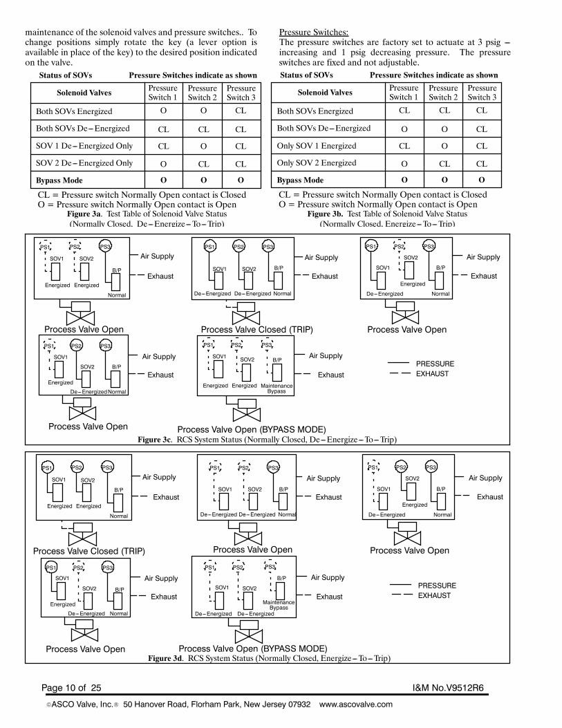
Figure 5 B. Enclosure Openings
7.01.0
19.0
1.0left side
left side
right side
right side
Stainless Steel
Composite Enclosures
7.01.0
19.0
6.5
5.0
1.0
18.5
6.5
5.01.0
18.5
1.0
Enclosures
Enclosure openings arepermitted in shadedareas. Multiple openingsmust have a minimum of4.0 inches spacing.Maximum number ofenclosure openings is 4per side.
Entry of external conductorsand cable must be thruproperly installed andsuitable flame proof cableentry devices and conformto local and national wiringcodes and zone 1 ATEXrequirements.
Figure 5 C. Grounding Connections
Internal grounding/earthinglocation (stud not visible)
External grounding/earthing location
Wiring GuidelinesThe following general guidelines apply to all wiringdiscussed in this document.
WARNING: Circuit power must be removedfrom the device prior to disconnecting the wiringon either the field or internal side of the terminalstrip.
S Wiring shall be according to the National ElectricalCode (ANSI---NFPA 70), Zone 1 ATEX requirementsor other applicable codes.
S Wire size: stranded 16 and 18 AWG.S The terminal clamps are designed for one wire only; DONOT attempt to terminate multiple wires into oneterminal.

Page 9 of 25I&M No.V9512R6
EASCO Valve, Inc.R 50 Hanover Road, Florham Park, New Jersey 07932 www.ascovalve.com
S Use care when running signal wiring near to or crossingconduit or wiring that supplies power to motors,solenoids, lighting, horns, bells, etc.
S AC power wiring should be run in a separate conduitfromDC power. All power wiring to and from the RCSshould be in grounded conduit.
S The RCS should be connected to a high qualityinstrument grade ground with #14 AWG or heavierwire. A grounding stud is provided both inside andoutside the enclosure.
Electrical Connection (Customer Responsibility):General (Figure 5 B)1. In all cases follow local and national electrical codes and
confirm compliance with Zone 1 ATEX requirements.2. Placement of the conduit connection is up to the customer,
in compliance with Zone 1, ATEX requirements, basedon location and ease of installation. The upper or lower leftside of the box will give the shortest run to the wire terminal.
3. Cable/conduit connections can be added in location as shownon Figure 5 B. Entry of external conductors and cables mustbe through properly installed and suitable certifiedflameproof cable entry devices and in accordance withATEXZone 1 increased safety requirements. Assemble and installcable glands per manufacturer’s instructions. Connect cableground connections to the grounding/earthing terminalblocks or grounding / earth studs provided internally andexternally.
4. It is recommended that standard industry practices arefollowed to prevent condensation fromentering the enclosureand, in some cases of Class I, Div. 2 or ATEX Zone 1conditions, to prevent hazardous gasses and vapors frommigrating through the conduit to the control room or openignition source.
Grounding and Earthing. (Figure 5 C)Internal and external grounding studs are provided on theRCSproduct. Ground/earth the product in accordance with localand national electric codes as well as ATEX Zone 1requirements. Green earthing terminal blocks are provided foreasy installation of conductor up to 4 mm sq.Only insert one conductorper terminal block. Grounding studsare provided inside and outside of the enclosure for additionalgrounding/earthing requirements. (see Figure 5 C)RCS---R Base Unit (without on---board PLC)1. Connect the power source to the designated terminals
(SOV1, SOV2)asperwiring diagramprovidedwith theRCSunit. Wiring diagrams are available on the Internet at:www.ascovalve.com/rcsconfigurator
2. Wire the three pressure switches (PS1, PS2 & PS3) as perwiring diagram.
3. Wire optional accessories.RCS---L Base Unit (with on---board PLC)1. Connect to the PLCas perwiring diagramprovidedwith the
RCS unit. Wiring diagrams are available on the Internet at:www.ascovalve.com/rcsconfigurator (SOV1, SOV2, PS1,PS2 and PS3 are pre---wired to PLC by ASCO
2. Use care when running signal wiring near to or crossingconduit or wiring that supplies power to motors,solenoids, lighting, horns, bells, etc.
3. AC power wiring should be run in a separate conduitfromDCpower. All power wiring to and from theRCSshould be in grounded conduit.
4. The RCS should be connected to a high qualityinstrument grade ground with #14 AWG or heavierwire. A grounding stud is provided both inside andoutside the enclosure.
Section 1. --- Normally Closed1. General OperationThe RCS is a two---out---of---two (2oo2) or one---out---of---onehot standby (1oo1HS) voting, solenoid---operated valve systemdesigned for use as a component in safety instrumentedsystems. It functions as a redundant pneumatic tripping deviceto control the pilot air signal to a process valve actuator. Bothsolenoids must be de---energized (De---Energize---To---TripVersion) or energized (Energize---To---Trip Version) prior tomoving the process to its fail---safe position.Three pressure switches are included to provide indication ofeach solenoid---operated valve and bypass valve position.The RCS allows for periodic testing of the solenoids by cyclingone solenoid valve and then the other either manually (whenordered with a local initiation of SOV test option) orautomatically (by the system DCS or the onboard diagnosticprocessor in the case of a 5L unit) therefore maintaining thedesired safety availability. This testing is performed onlinewithout the need for bypassing of the safety action andwithoutinterruption of the system process.Under normal operating conditions, the RCS supplies pilot airto the process valve actuator through the “process” port. Whena trip occurs, the RCS blocks the incoming pneumatic signaland connects the “process” port to the “exhaust” port. Thisvents the air signal from the process valve actuator and allowsthe actuator return spring to move the process to its fail---safeposition.The pressure switches report solenoid valve positions as follows:RUNMODE:S De---Energize---To---Trip:(Figure3a)If solenoid valve#1 (resp. #2) is in the energized position,the contact of pressure switch #1 (resp. #2) is open.Pressure vents frompressure switch#1 (resp#2). Pressureis applied to pressure switch #3 and contact closed.
S Energize---To---Trip:(Figure 3b)If solenoid valve #1 (resp. #2) is in the de---energizedposition, the contact of pressure switch #1 (resp. #2) isopen. Pressure vents from pressure switch #1 (resp. #2).Pressure is applied to pressure switch #3 and contact closed.
BYPASS MODE:S The manually operated maintenance bypass valve is usedto isolate and depressurize the solenoid valves andpressure switches during maintenance. The maintenancebypass valve position is indicated by pressure switch #3.
S In the Bypass mode, the RCS “inlet” port is directlyconnected to the “process” port. The solenoid valves andpressure switches are vented to “exhaust”.
S In the Bypass mode, the contacts of pressure switches #1,#2 and #3 are open which indicates that no pressure is onthe valves or pressure switches.
Manually---Actuated maintenance bypass valve operation:The manually---actuated bypass valve has two positions:NORMAL for system run and MAINTENANCE BYPASS for
Page 10 of 25 I&M No.V9512R6
EASCO Valve, Inc.R 50 Hanover Road, Florham Park, New Jersey 07932 www.ascovalve.com
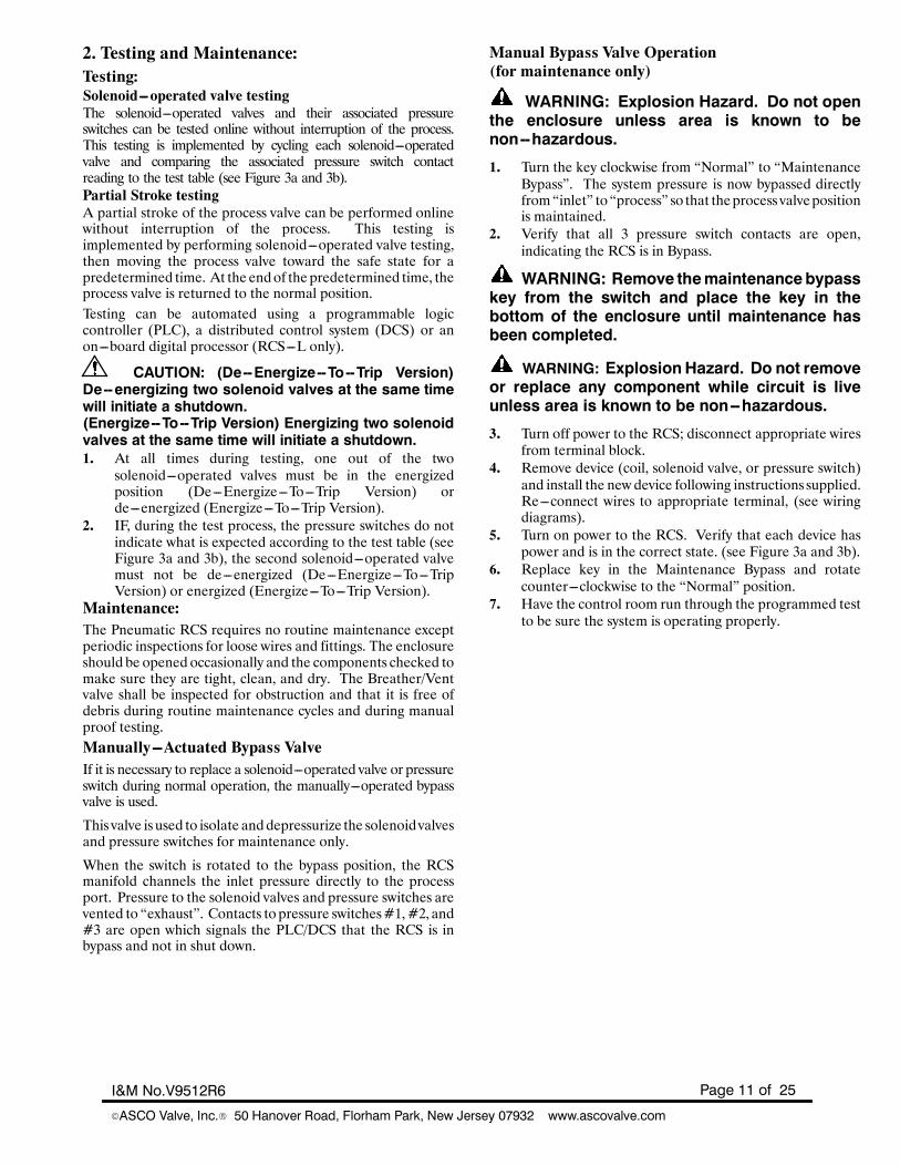
maintenance of the solenoid valves and pressure switches.. Tochange positions simply rotate the key (a lever option isavailable in place of the key) to the desired position indicatedon the valve.
Pressure Switches:The pressure switches are factory set to actuate at 3 psig ---increasing and 1 psig decreasing pressure. The pressureswitches are fixed and not adjustable.
Figure 3a. Test Table of Solenoid Valve Status(Normally Closed, De---Energize---To---Trip)
Figure 3b. Test Table of Solenoid Valve Status(Normally Closed, Energize---To---Trip)
Status of SOVs Pressure Switches indicate as shown
Solenoid Valves PressureSwitch 1
PressureSwitch 2
PressureSwitch 3
Both SOVs Energized
Both SOVs De---Energized
SOV 1 De---Energized Only
SOV 2 De---Energized Only
Bypass Mode
CL CL CL
CL
CL
CLCL
CL
O O
O
O
O O O
CL = Pressure switch Normally Open contact is ClosedO = Pressure switch Normally Open contact is Open
Status of SOVs Pressure Switches indicate as shown
Solenoid Valves PressureSwitch 1
PressureSwitch 2
PressureSwitch 3
Both SOVs Energized
Both SOVs De---Energized
Only SOV 1 Energized
Only SOV 2 Energized
Bypass Mode
O O CL
CL
CL
CLCL
CL
CL CL
O
O
O O O
CL = Pressure switch Normally Open contact is ClosedO = Pressure switch Normally Open contact is Open
Figure 3c. RCS System Status (Normally Closed, De---Energize---To---Trip)
PS1 PS2 PS3
Air Supply
Exhaust
Process Valve Open
SOV1 SOV2
B/P
PS1 PS2 PS3
Air Supply
Exhaust
Process Valve Closed (TRIP)
SOV1 SOV2 B/P
PS1 PS2 PS3
Air Supply
Exhaust
Process Valve Open
SOV1
SOV2
B/P
PS1 PS2 PS3
Air Supply
Exhaust
Process Valve Open (BYPASS MODE)
SOV1 SOV2 B/P
PS1 PS2 PS3
Air Supply
Exhaust
Process Valve Open
SOV1
SOV2 B/P PRESSUREEXHAUST
De---Energized
Energized
Normal
Energized Energized MaintenanceBypass
Energized
De---EnergizedNormal
Normal
EnergizedEnergizedDe---EnergizedDe---Energized Normal
Figure 3d. RCS System Status (Normally Closed, Energize---To---Trip)
PS1 PS2 PS3
Air Supply
Exhaust
Process Valve Closed (TRIP)
SOV1 SOV2
B/P
PS1 PS2 PS3
Air Supply
Exhaust
Process Valve Open
SOV1 SOV2 B/P
PS1 PS2 PS3
Air Supply
Exhaust
Process Valve Open
SOV1
SOV2
B/P
PS1 PS2 PS3
Air Supply
Exhaust
Process Valve Open (BYPASS MODE)
SOV1 SOV2
B/P
PS1 PS2 PS3
Air Supply
Exhaust
Process Valve Open
SOV1
SOV2 B/PPRESSUREEXHAUST
De---Energized
Energized
Normal
De---Energized De---Energized
MaintenanceBypassEnergized
De---Energized Normal
Normal
EnergizedEnergizedDe---EnergizedDe---Energized Normal
Page 11 of 25I&M No.V9512R6
EASCO Valve, Inc.R 50 Hanover Road, Florham Park, New Jersey 07932 www.ascovalve.com
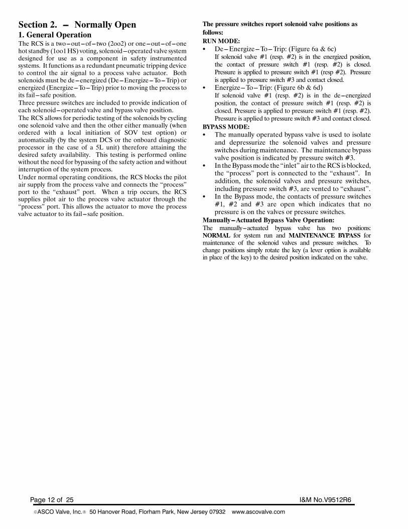
2. Testing and Maintenance:Testing:Solenoid---operated valve testingThe solenoid---operated valves and their associated pressureswitches can be tested online without interruption of the process.This testing is implemented by cycling each solenoid---operatedvalve and comparing the associated pressure switch contactreading to the test table (see Figure 3a and 3b).Partial Stroke testingA partial stroke of the process valve can be performed onlinewithout interruption of the process. This testing isimplemented by performing solenoid---operated valve testing,then moving the process valve toward the safe state for apredetermined time. At the endof the predetermined time, theprocess valve is returned to the normal position.Testing can be automated using a programmable logiccontroller (PLC), a distributed control system (DCS) or anon---board digital processor (RCS---L only).
CAUTION: (De--Energize--To--Trip Version)De--energizing two solenoid valves at the same timewill initiate a shutdown.(Energize--To--Trip Version) Energizing two solenoidvalves at the same time will initiate a shutdown.1. At all times during testing, one out of the two
solenoid---operated valves must be in the energizedposition (De---Energize---To---Trip Version) orde---energized (Energize---To---Trip Version).
2. IF, during the test process, the pressure switches do notindicate what is expected according to the test table (seeFigure 3a and 3b), the second solenoid---operated valvemust not be de---energized (De---Energize---To---TripVersion) or energized (Energize---To---Trip Version).
Maintenance:The Pneumatic RCS requires no routine maintenance exceptperiodic inspections for loose wires and fittings. The enclosureshould be opened occasionally and the components checked tomake sure they are tight, clean, and dry. The Breather/Ventvalve shall be inspected for obstruction and that it is free ofdebris during routine maintenance cycles and during manualproof testing.Manually---Actuated Bypass ValveIf it is necessary to replace a solenoid---operated valve or pressureswitch during normal operation, the manually---operated bypassvalve is used.
This valve is used to isolate anddepressurize the solenoidvalvesand pressure switches for maintenance only.
When the switch is rotated to the bypass position, the RCSmanifold channels the inlet pressure directly to the processport. Pressure to the solenoid valves and pressure switches arevented to “exhaust”. Contacts to pressure switches#1,#2, and#3 are open which signals the PLC/DCS that the RCS is inbypass and not in shut down.
Manual Bypass Valve Operation(for maintenance only)
WARNING: Explosion Hazard. Do not openthe enclosure unless area is known to benon--hazardous.
1. Turn the key clockwise from “Normal” to “MaintenanceBypass”. The system pressure is now bypassed directlyfrom“inlet” to “process” so that theprocess valvepositionis maintained.
2. Verify that all 3 pressure switch contacts are open,indicating the RCS is in Bypass.
WARNING: Remove themaintenancebypasskey from the switch and place the key in thebottom of the enclosure until maintenance hasbeen completed.
WARNING: ExplosionHazard. Do not removeor replace any component while circuit is liveunless area is known to be non--hazardous.
3. Turn off power to the RCS; disconnect appropriate wiresfrom terminal block.
4. Remove device (coil, solenoid valve, or pressure switch)and install the new device following instructions supplied.Re---connect wires to appropriate terminal, (see wiringdiagrams).
5. Turn on power to the RCS. Verify that each device haspower and is in the correct state. (see Figure 3a and 3b).
6. Replace key in the Maintenance Bypass and rotatecounter---clockwise to the “Normal” position.
7. Have the control room run through the programmed testto be sure the system is operating properly.
Page 12 of 25 I&M No.V9512R6
EASCO Valve, Inc.R 50 Hanover Road, Florham Park, New Jersey 07932 www.ascovalve.com
Section 2. --- Normally Open1. General OperationThe RCS is a two---out---of---two (2oo2) or one---out---of---onehot standby (1oo1HS) voting, solenoid---operated valve systemdesigned for use as a component in safety instrumentedsystems. It functions as a redundant pneumatic tripping deviceto control the air signal to a process valve actuator. Bothsolenoids must be de---energized (De---Energize---To---Trip) orenergized (Energize---To---Trip) prior to moving the process toits fail---safe position.Three pressure switches are included to provide indication ofeach solenoid---operated valve and bypass valve position.The RCS allows for periodic testing of the solenoids by cyclingone solenoid valve and then the other either manually (whenordered with a local initiation of SOV test option) orautomatically (by the system DCS or the onboard diagnosticprocessor in the case of a 5L unit) therefore attaining thedesired safety availability. This testing is performed onlinewithout the need for bypassing of the safety action andwithoutinterruption of the system process.Under normal operating conditions, the RCS blocks the pilotair supply from the process valve and connects the “process”port to the “exhaust” port. When a trip occurs, the RCSsupplies pilot air to the process valve actuator through the“process” port. This allows the actuator to move the processvalve actuator to its fail---safe position.
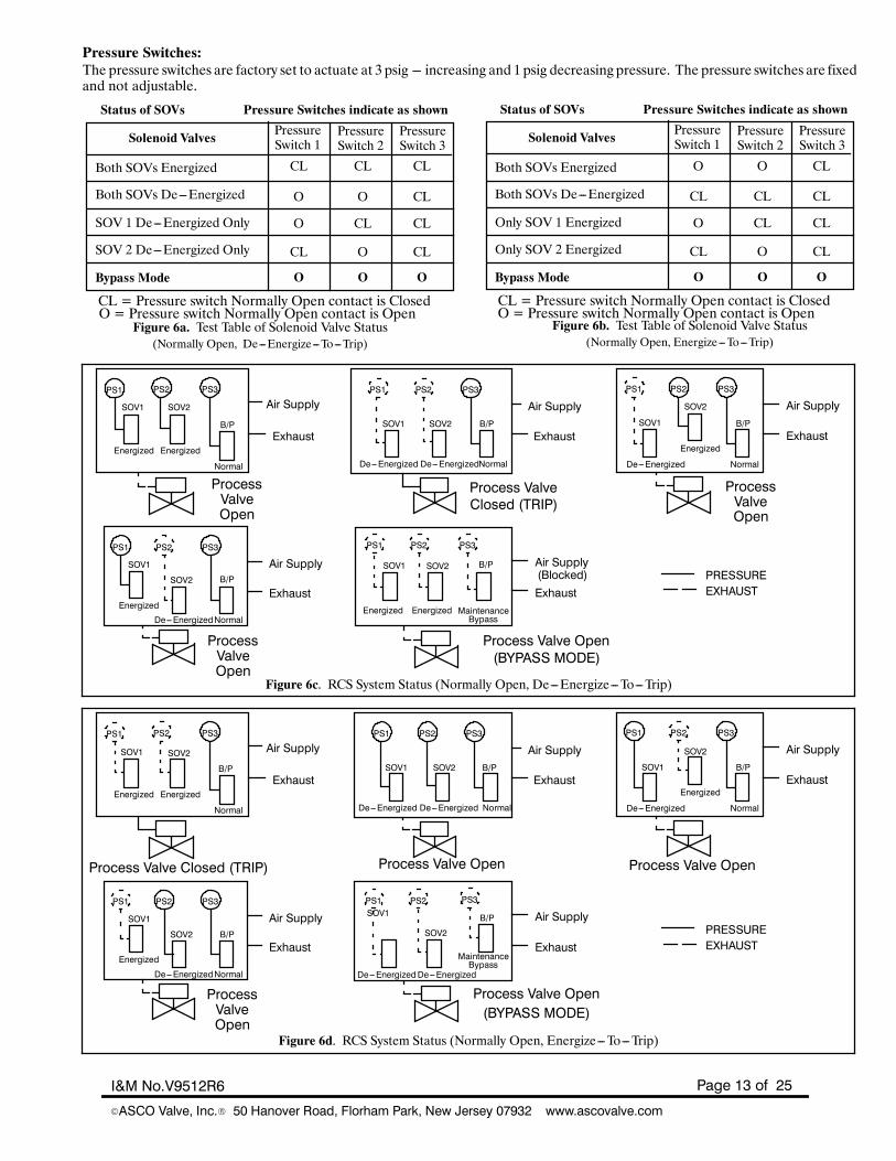
The pressure switches report solenoid valve positions asfollows:RUNMODE:S De---Energize---To---Trip: (Figure 6a & 6c)If solenoid valve #1 (resp. #2) is in the energized position,the contact of pressure switch #1 (resp. #2) is closed.Pressure is applied to pressure switch #1 (resp #2). Pressureis applied to pressure switch #3 and contact closed.
S Energize---To---Trip: (Figure 6b & 6d)If solenoid valve #1 (resp. #2) is in the de---energizedposition, the contact of pressure switch #1 (resp. #2) isclosed. Pressure is applied to pressure switch #1 (resp. #2).Pressure is applied to pressure switch #3 and contact closed.
BYPASS MODE:S The manually operated bypass valve is used to isolateand depressurize the solenoid valves and pressureswitches duringmaintenance. The maintenance bypassvalve position is indicated by pressure switch #3.
S In theBypassmode the “inlet” air to theRCS is blocked,the “process” port is connected to the “exhaust”. Inaddition, the solenoid valves and pressure switches,including pressure switch #3, are vented to “exhaust”.
S In the Bypass mode, the contacts of pressure switches#1, #2 and #3 are open which indicates that nopressure is on the valves or pressure switches.
Manually---Actuated Bypass Valve Operation:The manually---actuated bypass valve has two positions:NORMAL for system run and MAINTENANCE BYPASS formaintenance of the solenoid valves and pressure switches. Tochange positions simply rotate the key (a lever option is availablein place of the key) to the desired position indicated on the valve.
Page 13 of 25I&M No.V9512R6
EASCO Valve, Inc.R 50 Hanover Road, Florham Park, New Jersey 07932 www.ascovalve.com
Pressure Switches:The pressure switches are factory set to actuate at 3 psig --- increasing and 1 psig decreasing pressure. The pressure switches are fixedand not adjustable.
Figure 6b. Test Table of Solenoid Valve Status(Normally Open, Energize---To---Trip)
Status of SOVs Pressure Switches indicate as shown
Solenoid Valves PressureSwitch 1
PressureSwitch 2
PressureSwitch 3
Both SOVs Energized
Both SOVs De---Energized
SOV 1 De---Energized Only
SOV 2 De---Energized Only
Bypass Mode
O O CL
CL
CL
CLO
O
CL CL
CL
CL
O O O
CL = Pressure switch Normally Open contact is ClosedO = Pressure switch Normally Open contact is Open
Status of SOVs Pressure Switches indicate as shown
Solenoid Valves PressureSwitch 1
PressureSwitch 2
PressureSwitch 3
Both SOVs Energized
Both SOVs De---Energized
Only SOV 1 Energized
Only SOV 2 Energized
Bypass Mode
CL CL CL
CL
CL
CLO
O
O O
CL
CL
O O O
CL = Pressure switch Normally Open contact is ClosedO = Pressure switch Normally Open contact is Open
Figure 6a. Test Table of Solenoid Valve Status(Normally Open, De---Energize---To---Trip)
Figure 6c. RCS System Status (Normally Open, De---Energize---To---Trip)
PS1 PS2 PS3
Air Supply
Exhaust
SOV1 SOV2
B/P
PS1 PS2 PS3
Air Supply
ExhaustSOV1 SOV2 B/P
PS1 PS2 PS3
Air Supply
ExhaustSOV1
SOV2
B/P
PS1 PS2 PS3
Air Supply
Exhaust
SOV1 SOV2 B/P
PS1 PS2 PS3
Air Supply
Exhaust
SOV1
SOV2 B/P PRESSUREEXHAUST
De---Energized
Energized
Normal
Energized Energized MaintenanceBypass
Energized
De---EnergizedNormal
Normal
EnergizedEnergizedDe---EnergizedDe---Energized Normal
(Blocked)
ProcessValveOpen
ProcessValveOpen
Process ValveClosed (TRIP)
ProcessValveOpen
Process Valve Open(BYPASS MODE)
Figure 6d. RCS System Status (Normally Open, Energize---To---Trip)
PS1 PS2 PS3
Air Supply
Exhaust
Process Valve Closed (TRIP)
SOV1 SOV2
B/P
PS1 PS2 PS3
Air Supply
Exhaust
Process Valve Open
SOV1 SOV2 B/P
PS1 PS2 PS3
Air Supply
Exhaust
Process Valve Open
SOV1
SOV2
B/P
PS1 PS2 PS3
Air Supply
Exhaust
Process Valve Open(BYPASS MODE)
SOV1
SOV2
B/P
PS1 PS2 PS3
Air Supply
Exhaust
SOV1
SOV2 B/P PRESSUREEXHAUST
De---Energized
Energized
Normal
De---EnergizedDe---Energized
MaintenanceBypassEnergized
De---EnergizedNormal
Normal
EnergizedEnergizedDe---EnergizedDe---Energized Normal
ProcessValveOpen
Page 14 of 25 I&M No.V9512R6
EASCO Valve, Inc.R 50 Hanover Road, Florham Park, New Jersey 07932 www.ascovalve.com
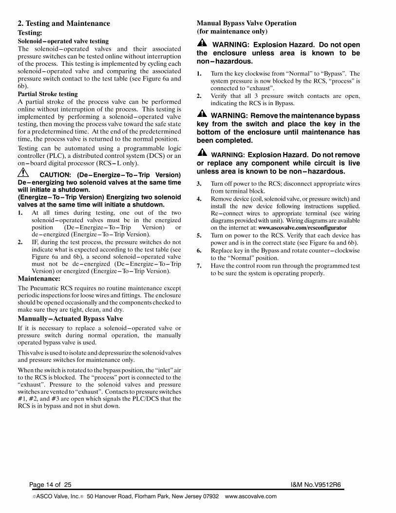
2. Testing and MaintenanceTesting:Solenoid---operated valve testingThe solenoid---operated valves and their associatedpressure switches can be tested online without interruptionof the process. This testing is implemented by cycling eachsolenoid---operated valve and comparing the associatedpressure switch contact to the test table (see Figure 6a and6b).Partial Stroke testingA partial stroke of the process valve can be performedonline without interruption of the process. This testing isimplemented by performing a solenoid---operated valvetesting, then moving the process valve toward the safe statefor a predetermined time. At the end of the predeterminedtime, the process valve is returned to the normal position.Testing can be automated using a programmable logiccontroller (PLC), a distributed control system (DCS) or anon---board digital processor (RCS---L only).
CAUTION: (De--Energize--To--Trip Version)De--energizing two solenoid valves at the same timewill initiate a shutdown.(Energize--To--Trip Version) Energizing two solenoidvalves at the same time will initiate a shutdown.1. At all times during testing, one out of the two
solenoid---operated valves must be in the energizedposition (De---Energize---To---Trip Version) orde---energized (Energize---To---Trip Version).
2. IF, during the test process, the pressure switches do notindicate what is expected according to the test table (seeFigure 6a and 6b), a second solenoid---operated valvemust not be de---energized (De---Energize---To---TripVersion) or energized (Energize---To---Trip Version).
Maintenance:The Pneumatic RCS requires no routine maintenance exceptperiodic inspections for loose wires and fittings. The enclosureshould be opened occasionally and the components checked tomake sure they are tight, clean, and dry.Manually---Actuated Bypass ValveIf it is necessary to replace a solenoid---operated valve orpressure switch during normal operation, the manuallyoperated bypass valve is used.
This valve is used to isolate anddepressurize the solenoidvalvesand pressure switches for maintenance only.
When the switch is rotated to the bypass position, the “inlet” airto the RCS is blocked. The “process” port is connected to the“exhaust”. Pressure to the solenoid valves and pressureswitches are vented to “exhaust”. Contacts to pressure switches#1, #2, and #3 are open which signals the PLC/DCS that theRCS is in bypass and not in shut down.
Manual Bypass Valve Operation(for maintenance only)
WARNING: Explosion Hazard. Do not openthe enclosure unless area is known to benon--hazardous.
1. Turn the key clockwise from “Normal” to “Bypass”. Thesystem pressure is now blocked by the RCS, “process” isconnected to “exhaust”.
2. Verify that all 3 pressure switch contacts are open,indicating the RCS is in Bypass.
WARNING: Remove themaintenancebypasskey from the switch and place the key in thebottom of the enclosure until maintenance hasbeen completed.
WARNING: ExplosionHazard. Do not removeor replace any component while circuit is liveunless area is known to be non--hazardous.
3. Turn off power to the RCS; disconnect appropriate wiresfrom terminal block.
4. Remove device (coil, solenoid valve, or pressure switch) andinstall the new device following instructions supplied.Re---connect wires to appropriate terminal (see wiringdiagramsprovidedwith unit). Wiring diagrams are availableon the internet at: www.ascovalve.com/rcsconfigurator
5. Turn on power to the RCS. Verify that each device haspower and is in the correct state (see Figure 6a and 6b).
6. Replace key in the Bypass and rotate counter---clockwiseto the “Normal” position.
7. Have the control room run through the programmed testto be sure the system is operating properly.
Page 15 of 25I&M No.V9512R6
EASCO Valve, Inc.R 50 Hanover Road, Florham Park, New Jersey 07932 www.ascovalve.com
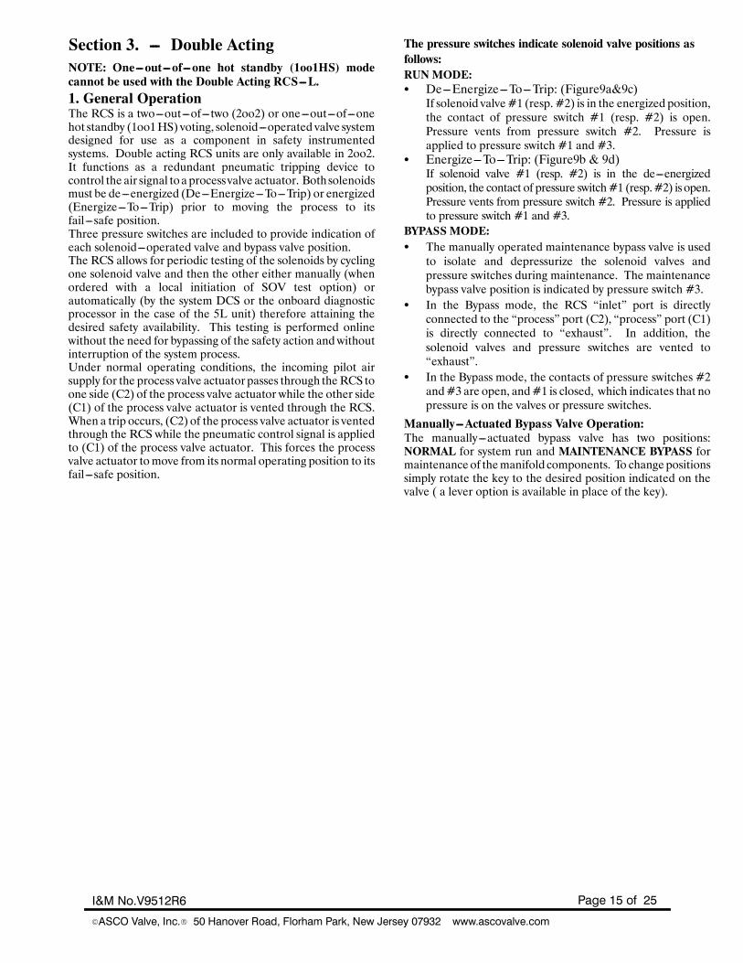
Section 3. --- Double ActingNOTE: One---out---of---one hot standby (1oo1HS) modecannot be used with the Double Acting RCS---L.1. General OperationThe RCS is a two---out---of---two (2oo2) or one---out---of---onehot standby (1oo1HS) voting, solenoid---operated valve systemdesigned for use as a component in safety instrumentedsystems. Double acting RCS units are only available in 2oo2.It functions as a redundant pneumatic tripping device tocontrol the air signal toa processvalve actuator. Bothsolenoidsmust be de---energized (De---Energize---To---Trip) or energized(Energize---To---Trip) prior to moving the process to itsfail---safe position.Three pressure switches are included to provide indication ofeach solenoid---operated valve and bypass valve position.The RCS allows for periodic testing of the solenoids by cyclingone solenoid valve and then the other either manually (whenordered with a local initiation of SOV test option) orautomatically (by the system DCS or the onboard diagnosticprocessor in the case of the 5L unit) therefore attaining thedesired safety availability. This testing is performed onlinewithout the need for bypassing of the safety action andwithoutinterruption of the system process.Under normal operating conditions, the incoming pilot airsupply for the process valve actuatorpasses through theRCS toone side (C2) of the process valve actuator while the other side(C1) of the process valve actuator is vented through the RCS.When a trip occurs, (C2) of the process valve actuator is ventedthrough the RCS while the pneumatic control signal is appliedto (C1) of the process valve actuator. This forces the processvalve actuator tomove from its normal operating position to itsfail---safe position.
The pressure switches indicate solenoid valve positions asfollows:RUNMODE:S De---Energize---To---Trip: (Figure9a&9c)If solenoid valve#1 (resp. #2) is in the energized position,the contact of pressure switch #1 (resp. #2) is open.Pressure vents from pressure switch #2. Pressure isapplied to pressure switch #1 and #3.
S Energize---To---Trip: (Figure9b & 9d)If solenoid valve #1 (resp. #2) is in the de---energizedposition, the contact of pressure switch#1 (resp.#2) is open.Pressure vents from pressure switch #2. Pressure is appliedto pressure switch #1 and #3.
BYPASS MODE:S The manually operated maintenance bypass valve is usedto isolate and depressurize the solenoid valves andpressure switches during maintenance. The maintenancebypass valve position is indicated by pressure switch #3.
S In the Bypass mode, the RCS “inlet” port is directlyconnected to the “process” port (C2), “process” port (C1)is directly connected to “exhaust”. In addition, thesolenoid valves and pressure switches are vented to“exhaust”.
S In the Bypass mode, the contacts of pressure switches #2and#3 are open, and#1 is closed, which indicates that nopressure is on the valves or pressure switches.
Manually---Actuated Bypass Valve Operation:The manually---actuated bypass valve has two positions:NORMAL for system run and MAINTENANCE BYPASS formaintenance of themanifold components. To changepositionssimply rotate the key to the desired position indicated on thevalve ( a lever option is available in place of the key).
Page 16 of 25 I&M No.V9512R6
EASCO Valve, Inc.R 50 Hanover Road, Florham Park, New Jersey 07932 www.ascovalve.com
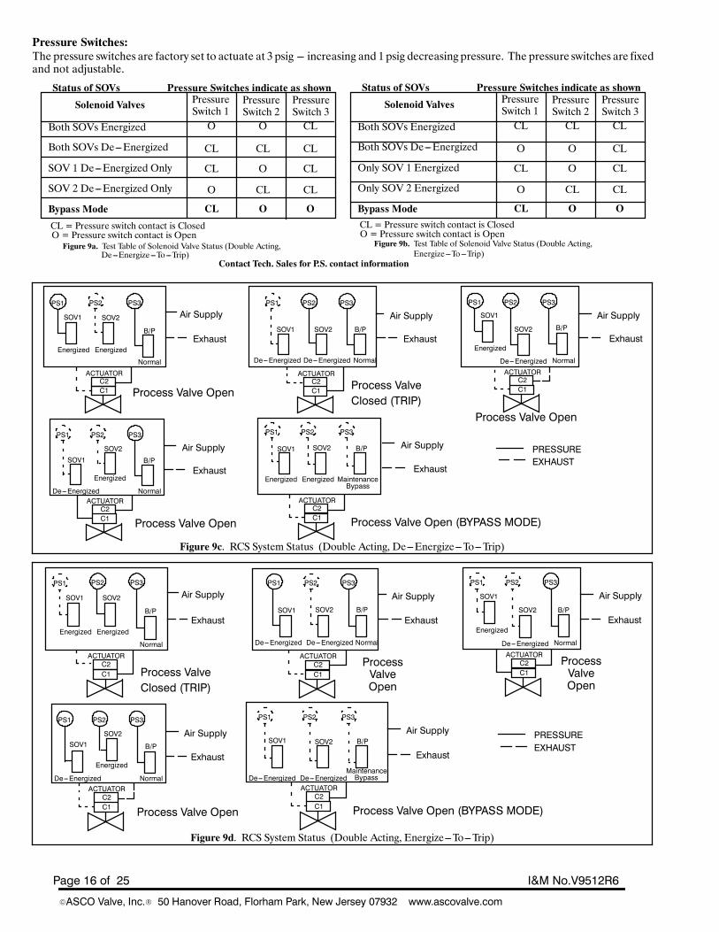
Pressure Switches:The pressure switches are factory set to actuate at 3 psig --- increasing and 1 psig decreasing pressure. The pressure switches are fixedand not adjustable.
Figure 9b. Test Table of Solenoid Valve Status (Double Acting,
Status of SOVs Pressure Switches indicate as shown
Solenoid Valves PressureSwitch 1
PressureSwitch 2
PressureSwitch 3
Both SOVs Energized
Both SOVs De---Energized
SOV 1 De---Energized Only
SOV 2 De---Energized Only
Bypass Mode
CL CL CL
CL
CL
CLCL
CL
O O
O
O
CL O O
CL = Pressure switch contact is ClosedO = Pressure switch contact is Open
Status of SOVs Pressure Switches indicate as shown
Solenoid Valves PressureSwitch 1
PressureSwitch 2
PressureSwitch 3
Both SOVs Energized
Both SOVs De---Energized
Only SOV 1 Energized
Only SOV 2 Energized
Bypass Mode
O O CL
CL
CL
CLCL
CL
CL CL
O
O
CL O OCL = Pressure switch contact is ClosedO = Pressure switch contact is Open
Figure 9a. Test Table of Solenoid Valve Status (Double Acting,De---Energize---To---Trip) Energize---To---Trip)
Contact Tech. Sales for P.S. contact information
Figure 9c. RCS System Status (Double Acting, De---Energize---To---Trip)
PS1 PS2 PS3
Air Supply
Exhaust
SOV1 SOV2
B/P
PS1 PS2 PS3
Air Supply
Exhaust
Process ValveClosed (TRIP)
SOV1 SOV2 B/P
PS1 PS2 PS3
Air Supply
Exhaust
Process Valve Open
SOV1
SOV2 B/P
PS1 PS2 PS3
Air Supply
Exhaust
Process Valve Open (BYPASS MODE)
SOV1 SOV2 B/P
PS1 PS2 PS3
Air Supply
Exhaust
Process Valve Open
SOV1
SOV2
B/PPRESSUREEXHAUST
Energized
De---Energized Normal
Energized Energized MaintenanceBypass
Energized
De---Energized Normal
Normal
EnergizedEnergizedDe---EnergizedDe---Energized Normal
C2C1
ACTUATOR
Process Valve OpenC2C1
ACTUATORC2C1
ACTUATOR
C2C1
ACTUATORC2C1
ACTUATOR
Figure 9d. RCS System Status (Double Acting, Energize---To---Trip)
PS1 PS2 PS3
Air Supply
Exhaust
SOV1 SOV2
B/P
PS1 PS2 PS3
Air Supply
ExhaustSOV1 SOV2 B/P
PS1 PS2 PS3
Air Supply
Exhaust
SOV1
SOV2 B/P
PS1 PS2 PS3
Air Supply
Exhaust
Process Valve Open (BYPASS MODE)
SOV1 SOV2 B/P
PS1 PS2 PS3
Air Supply
Exhaust
Process Valve Open
SOV1SOV2
B/PPRESSUREEXHAUST
Energized
De---Energized Normal
De---Energized De---EnergizedMaintenanceBypass
Energized
De---Energized Normal
Normal
EnergizedEnergizedDe---EnergizedDe---Energized Normal
C2C1
ACTUATOR
Process ValveClosed (TRIP)
C2C1
ACTUATORC2C1
ACTUATOR
C2C1
ACTUATORC2C1
ACTUATOR
ProcessValveOpen
ProcessValveOpen
Page 17 of 25I&M No.V9512R6
EASCO Valve, Inc.R 50 Hanover Road, Florham Park, New Jersey 07932 www.ascovalve.com
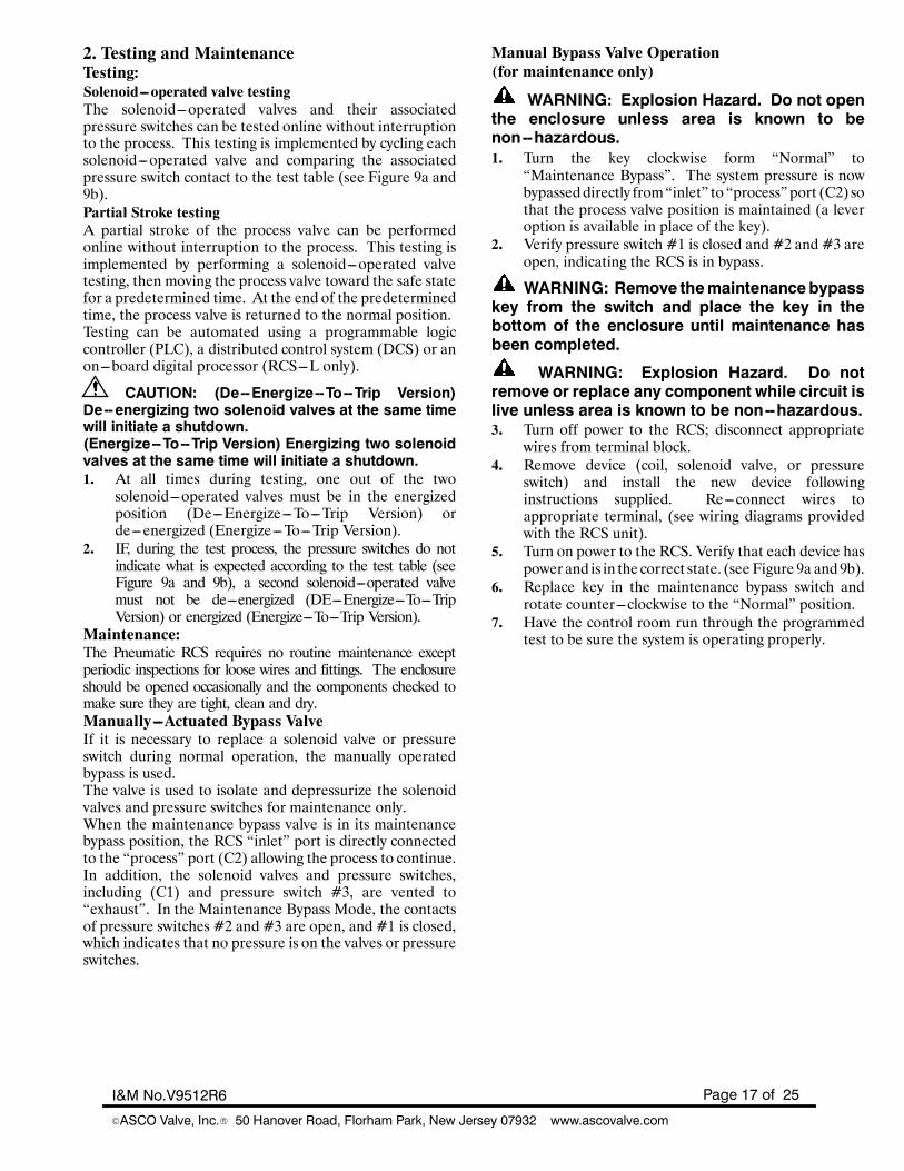
2. Testing and MaintenanceTesting:Solenoid---operated valve testingThe solenoid---operated valves and their associatedpressure switches can be tested online without interruptionto the process. This testing is implemented by cycling eachsolenoid---operated valve and comparing the associatedpressure switch contact to the test table (see Figure 9a and9b).Partial Stroke testingA partial stroke of the process valve can be performedonline without interruption to the process. This testing isimplemented by performing a solenoid---operated valvetesting, then moving the process valve toward the safe statefor a predetermined time. At the end of the predeterminedtime, the process valve is returned to the normal position.Testing can be automated using a programmable logiccontroller (PLC), a distributed control system (DCS) or anon---board digital processor (RCS---L only).
CAUTION: (De--Energize--To--Trip Version)De--energizing two solenoid valves at the same timewill initiate a shutdown.(Energize--To--Trip Version) Energizing two solenoidvalves at the same time will initiate a shutdown.1. At all times during testing, one out of the two
solenoid---operated valves must be in the energizedposition (De---Energize---To---Trip Version) orde---energized (Energize---To---Trip Version).
2. IF, during the test process, the pressure switches do notindicate what is expected according to the test table (seeFigure 9a and 9b), a second solenoid---operated valvemust not be de---energized (DE---Energize---To---TripVersion) or energized (Energize---To---Trip Version).
Maintenance:The Pneumatic RCS requires no routine maintenance exceptperiodic inspections for loose wires and fittings. The enclosureshould be opened occasionally and the components checked tomake sure they are tight, clean and dry.Manually---Actuated Bypass ValveIf it is necessary to replace a solenoid valve or pressureswitch during normal operation, the manually operatedbypass is used.The valve is used to isolate and depressurize the solenoidvalves and pressure switches for maintenance only.When the maintenance bypass valve is in its maintenancebypass position, the RCS “inlet” port is directly connectedto the “process” port (C2) allowing the process to continue.In addition, the solenoid valves and pressure switches,including (C1) and pressure switch #3, are vented to“exhaust”. In the Maintenance Bypass Mode, the contactsof pressure switches #2 and #3 are open, and #1 is closed,which indicates that no pressure is on the valves or pressureswitches.
Manual Bypass Valve Operation(for maintenance only)
WARNING: Explosion Hazard. Do not openthe enclosure unless area is known to benon--hazardous.1. Turn the key clockwise form “Normal” to
“Maintenance Bypass”. The system pressure is nowbypasseddirectly from“inlet” to “process” port (C2) sothat the process valve position is maintained (a leveroption is available in place of the key).
2. Verify pressure switch #1 is closed and #2 and #3 areopen, indicating the RCS is in bypass.
WARNING: Remove themaintenancebypasskey from the switch and place the key in thebottom of the enclosure until maintenance hasbeen completed.
WARNING: Explosion Hazard. Do notremove or replace any component while circuit islive unless area is known to be non--hazardous.3. Turn off power to the RCS; disconnect appropriate
wires from terminal block.4. Remove device (coil, solenoid valve, or pressure
switch) and install the new device followinginstructions supplied. Re---connect wires toappropriate terminal, (see wiring diagrams providedwith the RCS unit).
5. Turn on power to the RCS. Verify that each device haspowerand is in the correct state. (see Figure 9a and9b).
6. Replace key in the maintenance bypass switch androtate counter---clockwise to the “Normal” position.
7. Have the control room run through the programmedtest to be sure the system is operating properly.
Page 18 of 25 I&M No.V9512R6
EASCO Valve, Inc.R 50 Hanover Road, Florham Park, New Jersey 07932 www.ascovalve.com
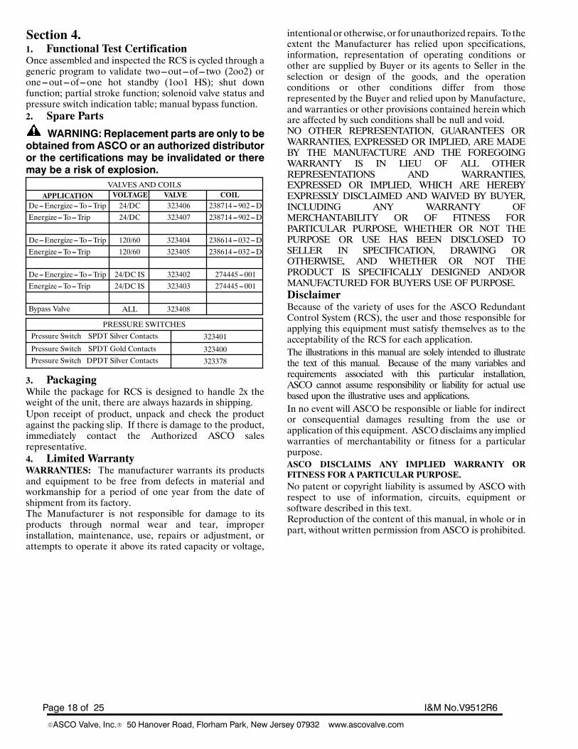
Section 4.1. Functional Test CertificationOnce assembled and inspected the RCS is cycled through ageneric program to validate two---out---of---two (2oo2) orone---out---of---one hot standby (1oo1 HS); shut downfunction; partial stroke function; solenoid valve status andpressure switch indication table; manual bypass function.2. Spare Parts
WARNING: Replacement parts are only to beobtained from ASCO or an authorized distributoror the certifications may be invalidated or theremay be a risk of explosion.
APPLICATION VOLTAGE VALVE COIL
Energize---To---TripDe---Energize---To---Trip
Bypass Valve
24/DC 323406 238714---902---D24/DC 323407 238714---902---D
Energize---To---TripDe---Energize---To---Trip 120/60 323404 238614---032---D
120/60 323405 238614---032---D
Energize---To---TripDe---Energize---To---Trip 24/DC IS 323402 274445---001
24/DC IS 323403 274445---001
VALVES AND COILS
ALL 323408
Pressure Switch
SPDT Gold Contacts
DPDT Silver Contacts
SPDT Silver Contacts
Pressure Switch
Pressure Switch
PRESSURE SWITCHES
323401
323400
323378
3. PackagingWhile the package for RCS is designed to handle 2x theweight of the unit, there are always hazards in shipping.Upon receipt of product, unpack and check the productagainst the packing slip. If there is damage to the product,immediately contact the Authorized ASCO salesrepresentative.4. Limited WarrantyWARRANTIES: The manufacturer warrants its productsand equipment to be free from defects in material andworkmanship for a period of one year from the date ofshipment from its factory.The Manufacturer is not responsible for damage to itsproducts through normal wear and tear, improperinstallation, maintenance, use, repairs or adjustment, orattempts to operate it above its rated capacity or voltage,
intentional or otherwise, or forunauthorized repairs. To theextent the Manufacturer has relied upon specifications,information, representation of operating conditions orother are supplied by Buyer or its agents to Seller in theselection or design of the goods, and the operationconditions or other conditions differ from thoserepresented by the Buyer and relied upon by Manufacture,and warranties or other provisions contained herein whichare affected by such conditions shall be null and void.NO OTHER REPRESENTATION, GUARANTEES ORWARRANTIES, EXPRESSED OR IMPLIED, ARE MADEBY THE MANUFACTURE AND THE FOREGOINGWARRANTY IS IN LIEU OF ALL OTHERREPRESENTATIONS AND WARRANTIES,EXPRESSED OR IMPLIED, WHICH ARE HEREBYEXPRESSLY DISCLAIMED AND WAIVED BY BUYER,INCLUDING ANY WARRANTY OFMERCHANTABILITY OR OF FITNESS FORPARTICULAR PURPOSE, WHETHER OR NOT THEPURPOSE OR USE HAS BEEN DISCLOSED TOSELLER IN SPECIFICATION, DRAWING OROTHERWISE, AND WHETHER OR NOT THEPRODUCT IS SPECIFICALLY DESIGNED AND/ORMANUFACTURED FOR BUYERS USE OF PURPOSE.DisclaimerBecause of the variety of uses for the ASCO RedundantControl System (RCS), the user and those responsible forapplying this equipment must satisfy themselves as to theacceptability of the RCS for each application.The illustrations in this manual are solely intended to illustratethe text of this manual. Because of the many variables andrequirements associated with this particular installation,ASCO cannot assume responsibility or liability for actual usebased upon the illustrative uses and applications.In no event will ASCO be responsible or liable for indirector consequential damages resulting from the use orapplication of this equipment. ASCOdisclaims any impliedwarranties of merchantability or fitness for a particularpurpose.ASCO DISCLAIMS ANY IMPLIED WARRANTY ORFITNESS FOR A PARTICULAR PURPOSE.No patent or copyright liability is assumed by ASCO withrespect to use of information, circuits, equipment orsoftware described in this text.Reproduction of the content of this manual, in whole or inpart, without written permission from ASCO is prohibited.
Page 19 of 25I&M No.V9512R6
EASCO Valve, Inc.R 50 Hanover Road, Florham Park, New Jersey 07932 www.ascovalve.com
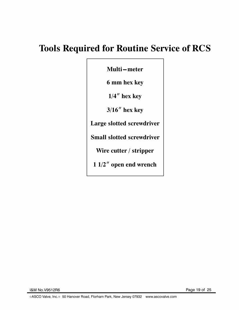
Tools Required for Routine Service of RCS
Multi---meter
6 mm hex key
1/4I hex key
3/16I hex key
1 1/2I open end wrench
Large slotted screwdriver
Small slotted screwdriver
Wire cutter / stripper
Page 20 of 25 I&M No.V9512R6
EASCO Valve, Inc.R 50 Hanover Road, Florham Park, New Jersey 07932 www.ascovalve.com
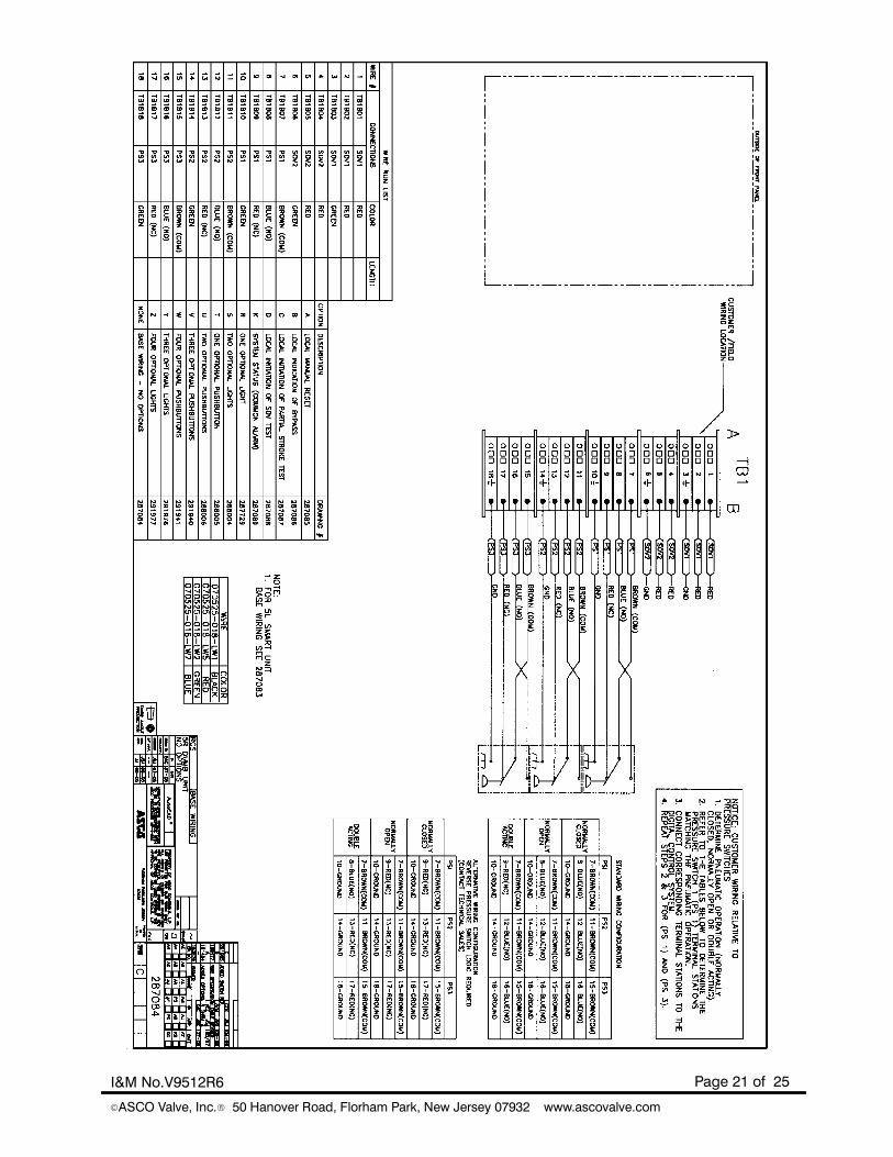
RCS---R Wiring Diagram (A)
Page 21 of 25I&M No.V9512R6
EASCO Valve, Inc.R 50 Hanover Road, Florham Park, New Jersey 07932 www.ascovalve.com
Page 22 of 25 I&M No.V9512R6
EASCO Valve, Inc.R 50 Hanover Road, Florham Park, New Jersey 07932 www.ascovalve.com
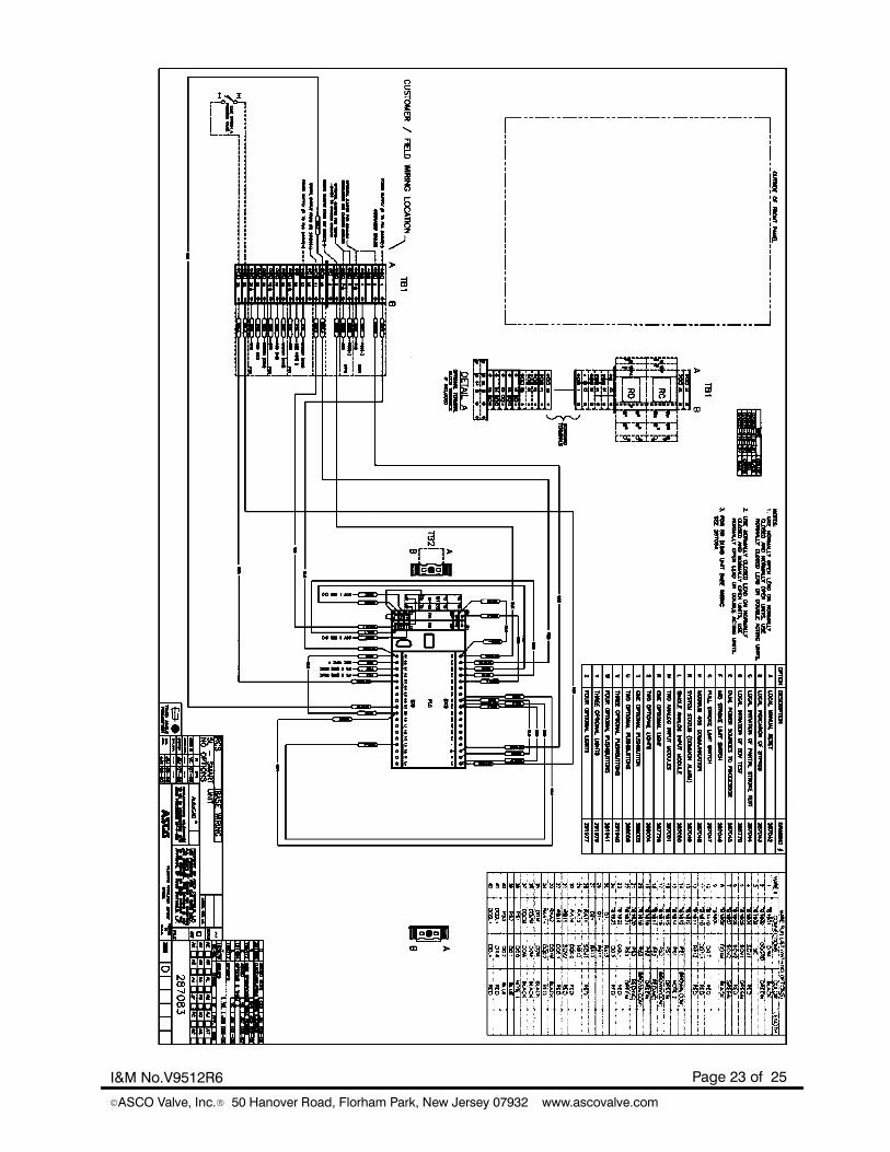
RCS---L Wiring Diagrams (B)
Page 23 of 25I&M No.V9512R6
EASCO Valve, Inc.R 50 Hanover Road, Florham Park, New Jersey 07932 www.ascovalve.com
Page 24 of 25 I&M No.V9512R6
EASCO Valve, Inc.R 50 Hanover Road, Florham Park, New Jersey 07932 www.ascovalve.com
For Future Pneumatic Schematic
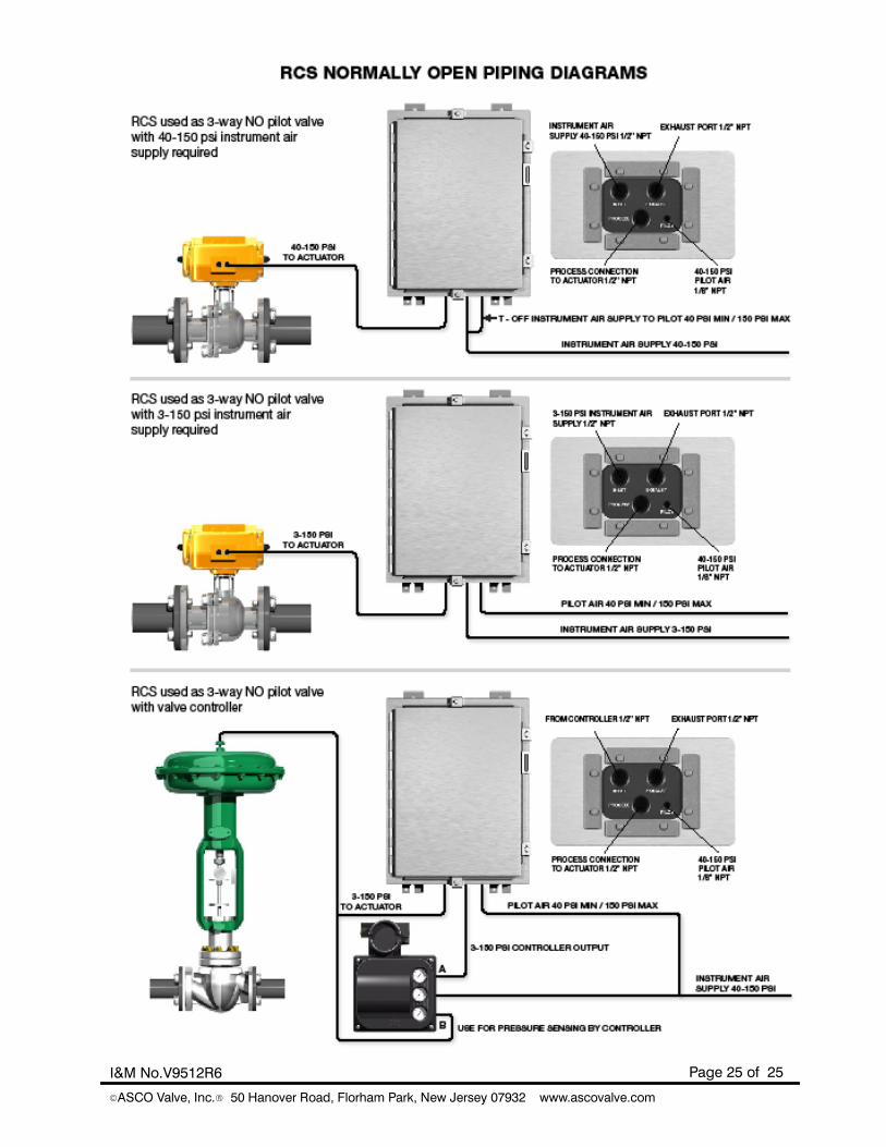
Page 25 of 25I&M No.V9512R6
EASCO Valve, Inc.R 50 Hanover Road, Florham Park, New Jersey 07932 www.ascovalve.com