Embed Size (px)
Citation preview
As an alignment environment, \psmatrix is similar to AMS-TEX’s \matrix.There is no argument for specifying the columns. Instead, you can justuse as many columns as you need. The entries are horizontally centered.Rows are ended by \\. \psmatrix can be used in or out of math mode.
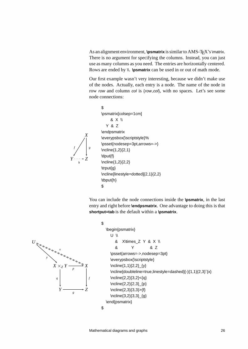
Our first example wasn’t very interesting, because we didn’t make useof the nodes. Actually, each entry is a node. The name of the node inrow row and column col is {row,col}, with no spaces. Let’s see somenode connections:
X
Y Z
f g
h
$
\psmatrix[colsep=1cm]
& X \\
Y & Z
\endpsmatrix
\everypsbox{\scriptstyle}%
\psset{nodesep=3pt,arrows=->}
\ncline{1,2}{2,1}
\tlput{f}
\ncline{1,2}{2,2}
\trput{g}
\ncline[linestyle=dotted]{2,1}{2,2}
\tbput{h}
$
You can include the node connections inside the \psmatrix, in the lastentry and right before \endpsmatrix. One advantage to doing this is thatshortput=tab is the default within a \psmatrix.
U
X�Z Y X
Y Z
y
x
q
p
f
g
$
\begin{psmatrix}
U \\
& X\times_Z Y & X \\
& Y & Z
\psset{arrows=->,nodesep=3pt}
\everypsbox{\scriptstyle}
\ncline{1,1}{2,2}_{y}
\ncline[doubleline=true,linestyle=dashed]{-}{1,1}{2,3}ˆ{x}
\ncline{2,2}{3,2}<{q}
\ncline{2,2}{2,3}_{p}
\ncline{2,3}{3,3}>{f}
\ncline{3,2}{3,3}_{g}
\end{psmatrix}
$
Mathematical diagrams and graphs 26
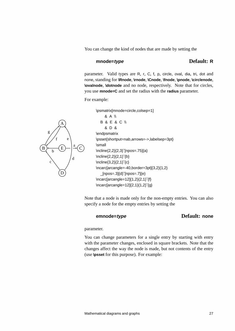
You can change the kind of nodes that are made by setting the
mnode=type Default: R
parameter. Valid types are R, r, C, f, p, circle, oval, dia, tri, dot andnone, standing for \Rnode, \rnode, \Cnode, \fnode, \pnode, \circlenode,\ovalnode, \dotnode and no node, respectively. Note that for circles,you use mnode=C and set the radius with the radius parameter.
For example:
A
B E C
D
ab
cd
ef
g
\psmatrix[mnode=circle,colsep=1]
& A \\
B & E & C \\
& D &
\endpsmatrix
\psset{shortput=nab,arrows=->,labelsep=3pt}
\small
\ncline{2,2}{2,3}ˆ[npos=.75]{a}
\ncline{2,2}{2,1}ˆ{b}
\ncline{3,2}{2,1}ˆ{c}
\ncarc[arcangle=-40,border=3pt]{3,2}{1,2}
_[npos=.3]{d}ˆ[npos=.7]{e}
\ncarc[arcangle=12]{1,2}{2,1}ˆ{f}
\ncarc[arcangle=12]{2,1}{1,2}ˆ{g}
Note that a node is made only for the non-empty entries. You can alsospecify a node for the empty entries by setting the
emnode=type Default: none
parameter.
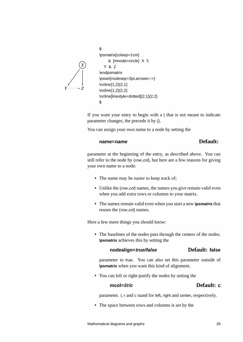
You can change parameters for a single entry by starting with entrywith the parameter changes, enclosed in square brackets. Note that thechanges affect the way the node is made, but not contents of the entry(use \psset for this purpose). For example:
Mathematical diagrams and graphs 27
X
Y Z
$
\psmatrix[colsep=1cm]
& [mnode=circle] X \\
Y & Z
\endpsmatrix
\psset{nodesep=3pt,arrows=->}
\ncline{1,2}{2,1}
\ncline{1,2}{2,2}
\ncline[linestyle=dotted]{2,1}{2,2}
$
If you want your entry to begin with a [ that is not meant to indicateparameter changes, the precede it by {}.
You can assign your own name to a node by setting the
name=name Default:
parameter at the beginning of the entry, as described above. You canstill refer to the node by {row,col}, but here are a few reasons for givingyour own name to a node:
• The name may be easier to keep track of;
• Unlike the {row,col} names, the names you give remain valid evenwhen you add extra rows or columns to your matrix.
• The names remain valid even when you start a new \psmatrix thatreuses the {row,col} names.
Here a few more things you should know:
• The baselines of the nodes pass through the centers of the nodes.\psmatrix achieves this by setting the
nodealign=true/false Default: false
parameter to true. You can also set this parameter outside of\psmatrix when you want this kind of alignment.
• You can left or right-justify the nodes by setting the
mcol=l/r/c Default: c
parameter. l, r and c stand for left, right and center, respectively.
• The space between rows and columns is set by the
Mathematical diagrams and graphs 28
rowsep=dim Default: 1.5cmcolsep=dim Default: 1.5cm
parameters.
• If you want all the nodes to have a fixed with, set
mnodesize=dim Default: -1pt
to a positive value.
• If \psmatrix is used in math mode, all the entries are set in mathmode, but you can switch a single entry out of math mode bystarting and ending the entry with $.
• The radius of the c mnode (corresponding to \cnode) is set by the
radius=dim Default: 2pt
parameter.
• Like in LaTEX, you can end a row with \\[dim] to insert an extraspace dim between rows.
• The command \psrowhookii is executed, if defined, at the begin-ning of every entry in row ii (row 2), and the command \pscolhookv
is executed at athe beginning of every entry in column v (etc.).You can use these hooks, for example, to change the spacing be-tween two columns, or to use a special mnode for all the entriesin a particular row.
• An entry can itself be a node. You might do this if you want anentry to have two shapes.
• If you want an entry to stretch across several (int) columns, usethe
\psspan{int}
at the end of the entry. This is like Plain TEX’s \multispan, orLaTEX’s \multicolumn, but the template for the current column (thefirst column that is spanned) is still used. If you want wipe outthe template as well, use \multispan{int} at the beginning of theentry instead. If you just want to wipe out the template, use \omit
before the entry.
Mathematical diagrams and graphs 29
• \psmatrix can be nested, but then all node connections and otherreferences to the nodes in the {row,col} form for the nested matrixmust go inside the \psmatrix. This is how PSTricks decideswhich matrix you are referring to. It is still neatest to put allthe node connections towards the end; just be sure to put thembefore \endpsmatrix. Be careful also not to refer to a node untilit actually appears. The whole matrix can itself go inside a node,and node connections can be made as usual. This is not the sameas connecting nodes from two different \psmatrix’s. To do this,you must give the nodes names and refer to them by these names.
12 Obsolete put commands
This is old documentation, but these commands will continue to besupported.
There is also an obsolete command \Lput for putting labels next to nodeconnections. The syntax is
\Lput{labelsep}[refpoint]{rotation}(pos){stuff }
It is a combination of \Rput and \lput, equivalent to
\lput(pos){\Rput{labelsep}[refpoint]{rotation}(0,0){stuff }}
\Mput is a short version of \Lput with no {rotation} or (pos) argument.\Lput and \Mput remain part of PSTricks only for backwards compati-bility.
Here are the node label commands:
\lput*[refpoint]{rotation}(pos){stuff}
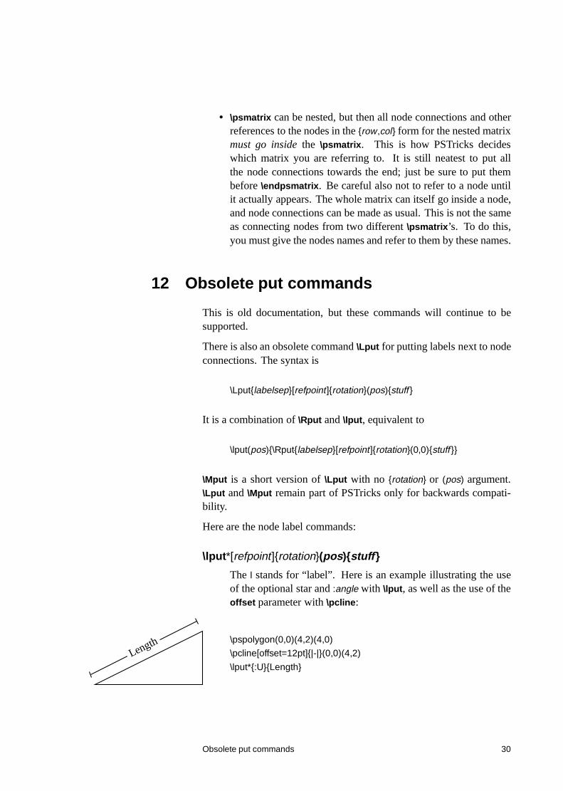
The l stands for “label”. Here is an example illustrating the useof the optional star and :angle with \lput, as well as the use of theoffset parameter with \pcline:
Length \pspolygon(0,0)(4,2)(4,0)
\pcline[offset=12pt]{|-|}(0,0)(4,2)
\lput*{:U}{Length}
Obsolete put commands 30
(Remember that with the put commands, you can omit the coor-dinate if you include the angle of rotation. You are likely to usethis feature with the node label commands.)
With \lput and \rput, you have a lot of control over the position ofthe label. E.g.,
label \pcline(0,0)(4,2)
\lput{:U}{\rput[r]{N}(0,.4){label}}
puts the label upright on the page, with right side located .4centimeters “above” the position .5 of the node connection (aboveif the node connection points to the right). However, the \aputand \bput commands described below handle the most commoncases without \rput.8
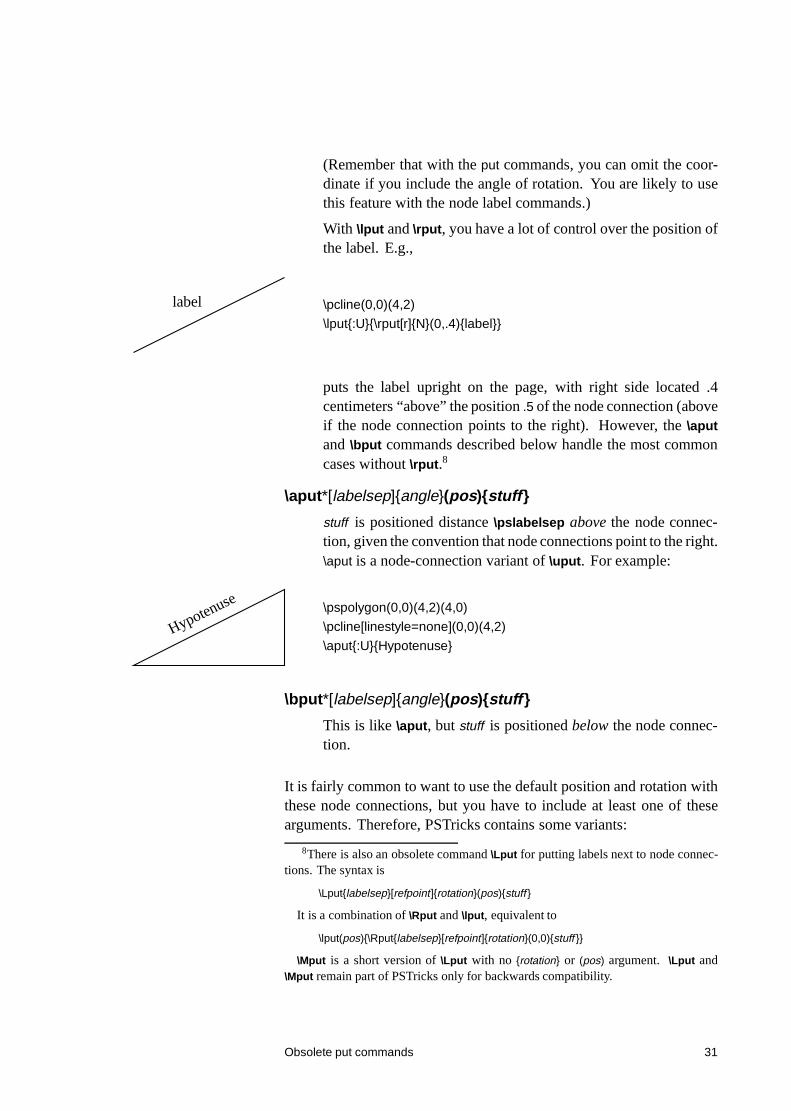
\aput*[labelsep]{angle}(pos){stuff }
stuff is positioned distance \pslabelsep above the node connec-tion, given the convention that node connections point to the right.\aput is a node-connection variant of \uput. For example:
Hypotenuse \pspolygon(0,0)(4,2)(4,0)
\pcline[linestyle=none](0,0)(4,2)
\aput{:U}{Hypotenuse}
\bput*[labelsep]{angle}(pos){stuff }
This is like \aput, but stuff is positioned below the node connec-tion.
It is fairly common to want to use the default position and rotation withthese node connections, but you have to include at least one of thesearguments. Therefore, PSTricks contains some variants:
8There is also an obsolete command \Lput for putting labels next to node connec-tions. The syntax is
\Lput{labelsep}[refpoint]{rotation}(pos){stuff }
It is a combination of \Rput and \lput, equivalent to
\lput(pos){\Rput{labelsep}[refpoint]{rotation}(0,0){stuff }}
\Mput is a short version of \Lput with no {rotation} or (pos) argument. \Lput and\Mput remain part of PSTricks only for backwards compatibility.
Obsolete put commands 31
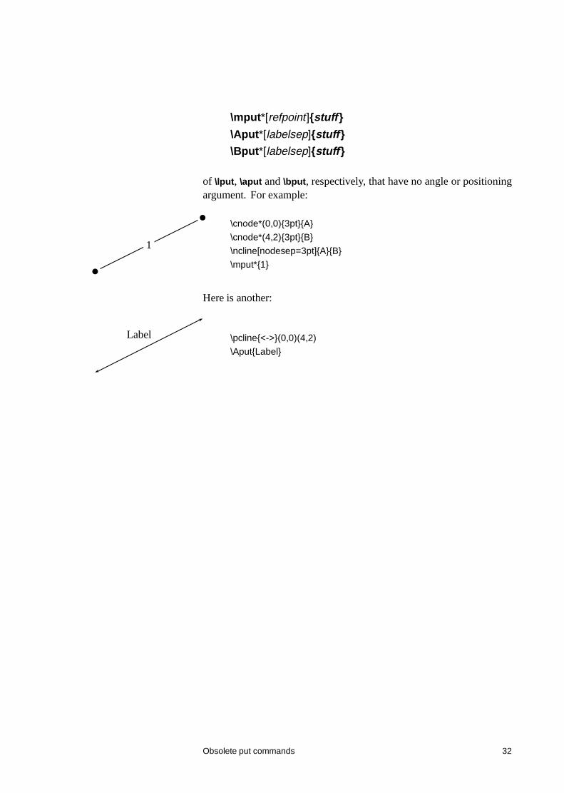
\mput*[refpoint]{stuff }
\Aput*[labelsep]{stuff }
\Bput*[labelsep]{stuff }
of \lput, \aput and \bput, respectively, that have no angle or positioningargument. For example:
1
\cnode*(0,0){3pt}{A}
\cnode*(4,2){3pt}{B}
\ncline[nodesep=3pt]{A}{B}
\mput*{1}
Here is another:
Label \pcline{<->}(0,0)(4,2)
\Aput{Label}
Obsolete put commands 32
II Trees
13 Overview
The node and node connections are perfect tools for making trees. Thepstree file pstree.tex / pstree.sty contains a high-level interface for positioning
the nodes in a tree.
The main tree macro is
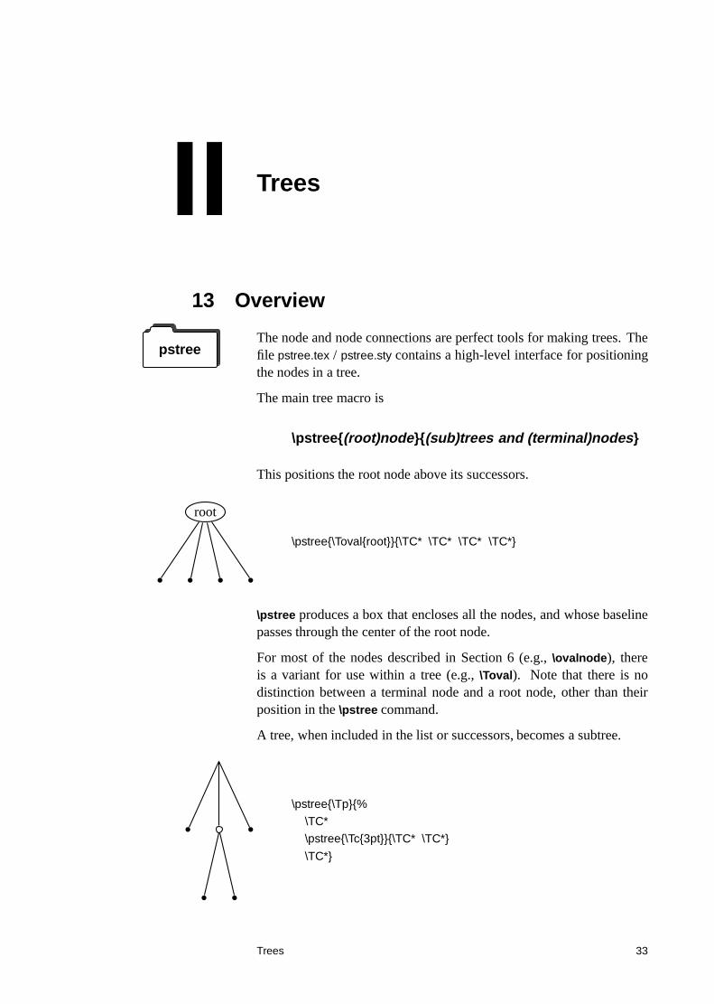
\pstree{(root)node}{(sub)trees and (terminal)nodes}
This positions the root node above its successors.
root
\pstree{\Toval{root}}{\TC* \TC* \TC* \TC*}
\pstree produces a box that encloses all the nodes, and whose baselinepasses through the center of the root node.
For most of the nodes described in Section 6 (e.g., \ovalnode), thereis a variant for use within a tree (e.g., \Toval). Note that there is nodistinction between a terminal node and a root node, other than theirposition in the \pstree command.
A tree, when included in the list or successors, becomes a subtree.
\pstree{\Tp}{%
\TC*
\pstree{\Tc{3pt}}{\TC* \TC*}
\TC*}
Trees 33
14 Tree Nodes
For most nodes described in Section 6, you can add strip node from theend of the name and add T add the beginning to obtain a node for usein trees. The syntax of a tree node is the same as of its corresponding“normal” node, except that:
• there is always an optional argument for setting graphics param-eters, even if the original node did not have one,
• there is no argument for specifying the name of the node, and
• there is never a coordinate argument for positioning the node.
• to set the reference point with \Tr, set the ref parameter.
Here is the list of such tree nodes:
\Tp*[par]
\Tc*[par]{dim}
\TC*[par]
\Tf*[par]
\Tdot*[par]
\Tr*[par]{stuff}
\TR*[par]{stuff}
\Tcircle*[par]{stuff }
\Toval*[par]{stuff }
\Tdia*[par]{stuff }
\Ttri*[par]{stuff }
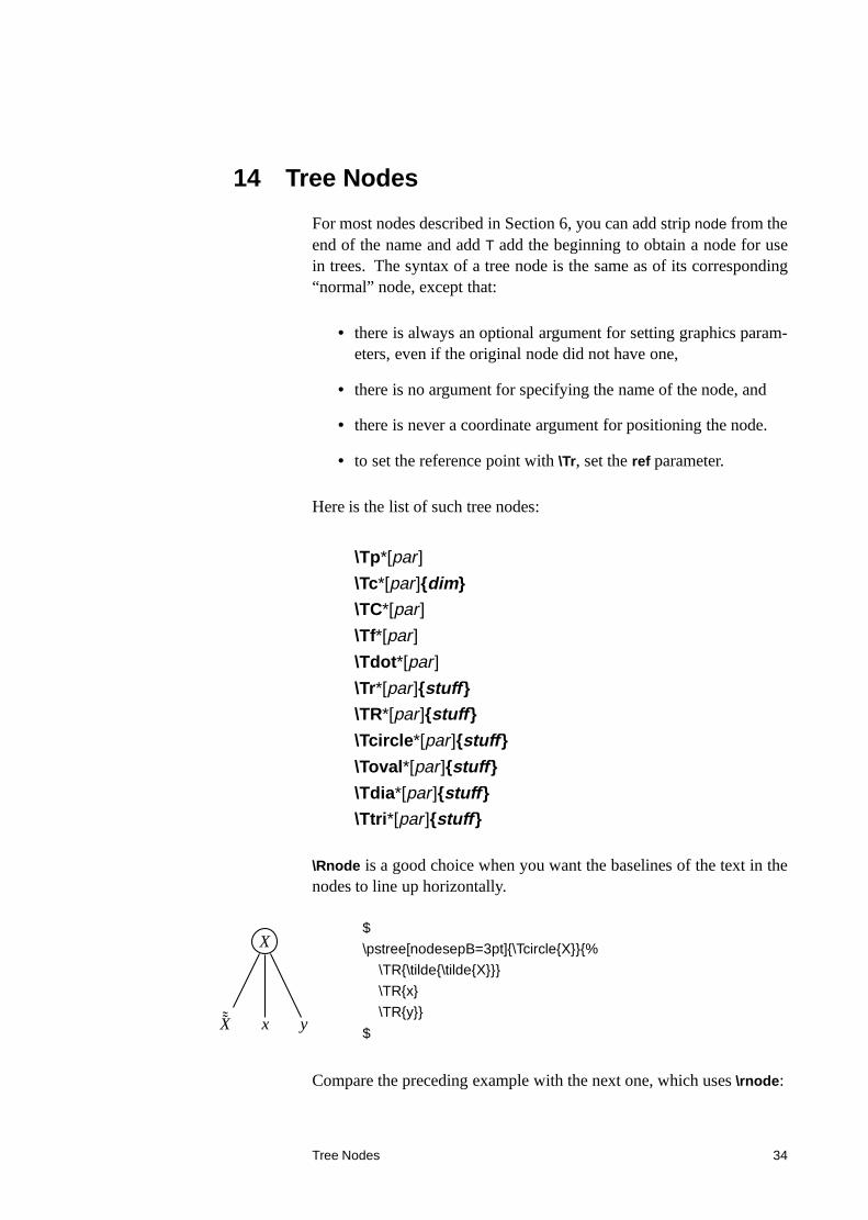
\Rnode is a good choice when you want the baselines of the text in thenodes to line up horizontally.
X
˜̃X x y
$
\pstree[nodesepB=3pt]{\Tcircle{X}}{%
\TR{\tilde{\tilde{X}}}
\TR{x}
\TR{y}}
$
Compare the preceding example with the next one, which uses \rnode:
Tree Nodes 34
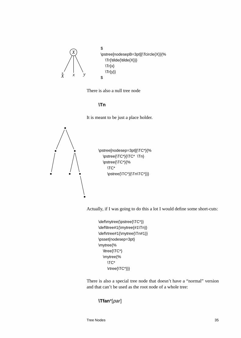
X
˜̃X x y
$
\pstree[nodesepB=3pt]{\Tcircle{X}}{%
\Tr{\tilde{\tilde{X}}}
\Tr{x}
\Tr{y}}
$
There is also a null tree node
\Tn
It is meant to be just a place holder.
\pstree[nodesep=3pt]{\TC*}{%
\pstree{\TC*}{\TC* \Tn}
\pstree{\TC*}{%
\TC*
\pstree{\TC*}{\Tn\TC*}}}
Actually, if I was going to do this a lot I would define some short-cuts:
\def\mytree{\pstree{\TC*}}
\def\ltree#1{\mytree{#1\Tn}}
\def\rtree#1{\mytree{\Tn#1}}
\psset{nodesep=3pt}
\mytree{%
\ltree{\TC*}
\mytree{%
\TC*
\rtree{\TC*}}}
There is also a special tree node that doesn’t have a “normal” versionand that can’t be used as the root node of a whole tree:
\Tfan*[par]
Tree Nodes 35
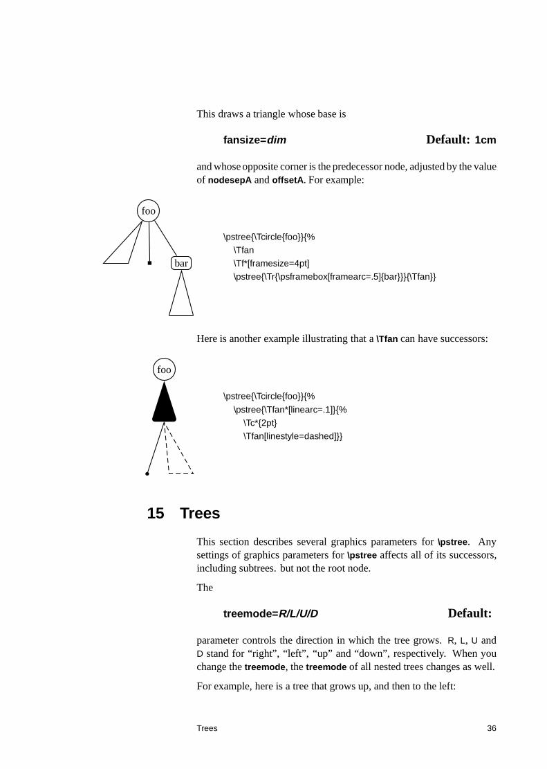
This draws a triangle whose base is
fansize=dim Default: 1cm
and whose opposite corner is the predecessor node, adjusted by the valueof nodesepA and offsetA. For example:
foo
bar
\pstree{\Tcircle{foo}}{%
\Tfan
\Tf*[framesize=4pt]
\pstree{\Tr{\psframebox[framearc=.5]{bar}}}{\Tfan}}
Here is another example illustrating that a \Tfan can have successors:
foo
\pstree{\Tcircle{foo}}{%
\pstree{\Tfan*[linearc=.1]}{%
\Tc*{2pt}
\Tfan[linestyle=dashed]}}
15 Trees
This section describes several graphics parameters for \pstree. Anysettings of graphics parameters for \pstree affects all of its successors,including subtrees. but not the root node.
The
treemode=R/L/U/D Default:
parameter controls the direction in which the tree grows. R, L, U andD stand for “right”, “left”, “up” and “down”, respectively. When youchange the treemode, the treemode of all nested trees changes as well.
For example, here is a tree that grows up, and then to the left:
Trees 36
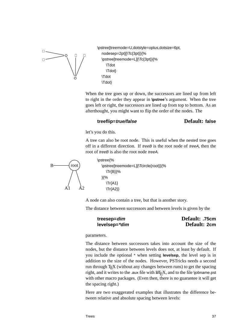
⊕
⊕⊕ ⊕
\pstree[treemode=U,dotstyle=oplus,dotsize=6pt,
nodesep=2pt]{\Tc{3pt}}{%
\pstree[treemode=L]{\Tc{3pt}}{%
\Tdot
\Tdot}
\Tdot
\Tdot}
When the tree goes up or down, the successors are lined up from leftto right in the order they appear in \pstree’s argument. When the treegoes left or right, the successors are lined up from top to bottom. As anafterthought, you might want to flip the order of the nodes. The
treeflip=true/false Default: false
let’s you do this.
A tree can also be root node. This is useful when the nested tree goesoff in a different direction. If treeB is the root node of treeA, then theroot of treeB is also the root node treeA.
rootB
A1 A2
\pstree{%
\pstree[treemode=L]{\Tcircle{root}}{%
\Tr{B}}%
}{%
\Tr{A1}
\Tr{A2}}
A node can also contain a tree, but that is another story.
The distance between successors and between levels is given by the
treesep=dim Default: .75cmlevelsep=*dim Default: 2cm
parameters.
The distance between successors takes into account the size of thenodes, but the distance between levels does not, at least by default. Ifyou include the optional * when setting levelsep, the level sep is inaddition to the size of the nodes. However, PSTricks needs a secondrun through TEX (without any changes between runs) to get the spacingright, and it writes to the .aux file with LaTEX, and to the file \jobname.pst
with other macro packages. (Even then, there is no guarantee it will getthe spacing right.)
Here are two exaggerated examples that illustrates the difference be-tween relative and absolute spacing between levels:
Trees 37
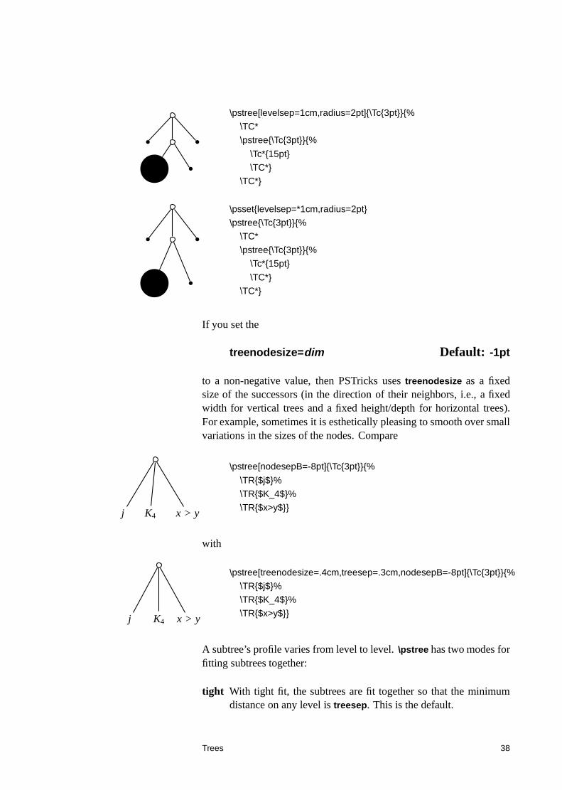
\pstree[levelsep=1cm,radius=2pt]{\Tc{3pt}}{%
\TC*
\pstree{\Tc{3pt}}{%
\Tc*{15pt}
\TC*}
\TC*}
\psset{levelsep=*1cm,radius=2pt}
\pstree{\Tc{3pt}}{%
\TC*
\pstree{\Tc{3pt}}{%
\Tc*{15pt}
\TC*}
\TC*}
If you set the
treenodesize=dim Default: -1pt
to a non-negative value, then PSTricks uses treenodesize as a fixedsize of the successors (in the direction of their neighbors, i.e., a fixedwidth for vertical trees and a fixed height/depth for horizontal trees).For example, sometimes it is esthetically pleasing to smooth over smallvariations in the sizes of the nodes. Compare
j K4 x > y
\pstree[nodesepB=-8pt]{\Tc{3pt}}{%
\TR{$j$}%
\TR{$K_4$}%
\TR{$x>y$}}
with
j K4 x > y
\pstree[treenodesize=.4cm,treesep=.3cm,nodesepB=-8pt]{\Tc{3pt}}{%
\TR{$j$}%
\TR{$K_4$}%
\TR{$x>y$}}
A subtree’s profile varies from level to level. \pstree has two modes forfitting subtrees together:
tight With tight fit, the subtrees are fit together so that the minimumdistance on any level is treesep. This is the default.
Trees 38
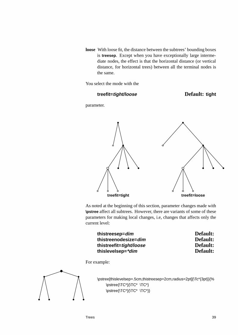
loose With loose fit, the distance between the subtrees’ bounding boxesis treesep. Except when you have exceptionally large interme-diate nodes, the effect is that the horizontal distance (or verticaldistance, for horizontal trees) between all the terminal nodes isthe same.
You select the mode with the
treefit=tight/loose Default: tight
parameter.
treefit=tight treefit=loose
As noted at the beginning of this section, parameter changes made with\pstree affect all subtrees. However, there are variants of some of theseparameters for making local changes, i.e, changes that affects only thecurrent level:
thistreesep=dim Default:thistreenodesize=dim Default:thistreefit=tight/loose Default:thislevelsep=*dim Default:
For example:
\pstree[thislevelsep=.5cm,thistreesep=2cm,radius=2pt]{\Tc*{3pt}}{%
\pstree{\TC*}{\TC* \TC*}
\pstree{\TC*}{\TC* \TC*}}
Trees 39
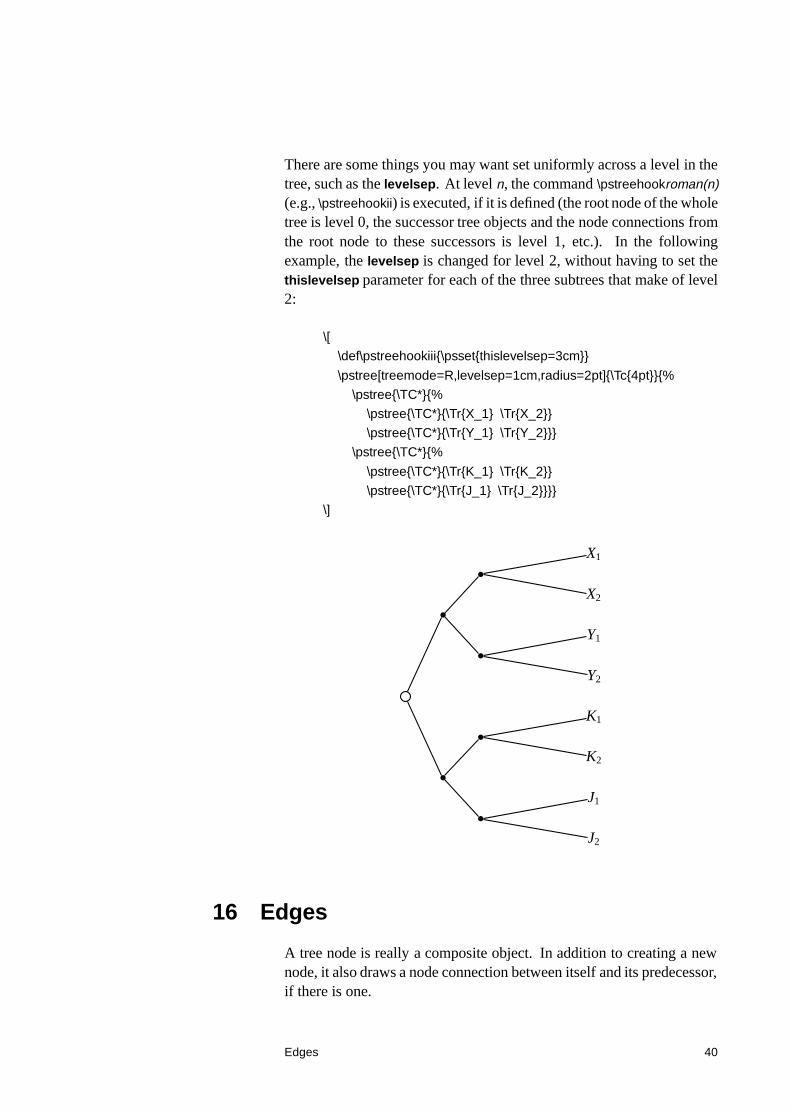
There are some things you may want set uniformly across a level in thetree, such as the levelsep. At level n, the command \pstreehookroman(n)(e.g., \pstreehookii) is executed, if it is defined (the root node of the wholetree is level 0, the successor tree objects and the node connections fromthe root node to these successors is level 1, etc.). In the followingexample, the levelsep is changed for level 2, without having to set thethislevelsep parameter for each of the three subtrees that make of level2:
\[
\def\pstreehookiii{\psset{thislevelsep=3cm}}
\pstree[treemode=R,levelsep=1cm,radius=2pt]{\Tc{4pt}}{%
\pstree{\TC*}{%
\pstree{\TC*}{\Tr{X_1} \Tr{X_2}}
\pstree{\TC*}{\Tr{Y_1} \Tr{Y_2}}}
\pstree{\TC*}{%
\pstree{\TC*}{\Tr{K_1} \Tr{K_2}}
\pstree{\TC*}{\Tr{J_1} \Tr{J_2}}}}
\]
X1
X2
Y1
Y2
K1
K2
J1
J2
16 Edges
A tree node is really a composite object. In addition to creating a newnode, it also draws a node connection between itself and its predecessor,if there is one.
Edges 40
When a tree node has made the new node, the command \pssucc isequal to the name of this node, and \pspred is equal to the name of itspredecessor. Then the tree node executes
\psedge{\pspred}{\pssucc}
You can define \psedge to make whatever node connection you want(see Section ??). For example, here I use \ncdiag, with armA=0, toget all the node connections to emanate from the same point in thepredecessor:
\def\psedge{\ncdiag[armA=0,angleB=180,armB=1cm]}
% Or: \renewcommand{\psedge}{ ... }
\pstree[treemode=R,levelsep=3.5cm,framesep=2pt]{\Tc{6pt}}{%
\small \Tcircle{N} \Tcircle{K} \Tcircle{H} \Tcircle{L}}
N
K
H
L
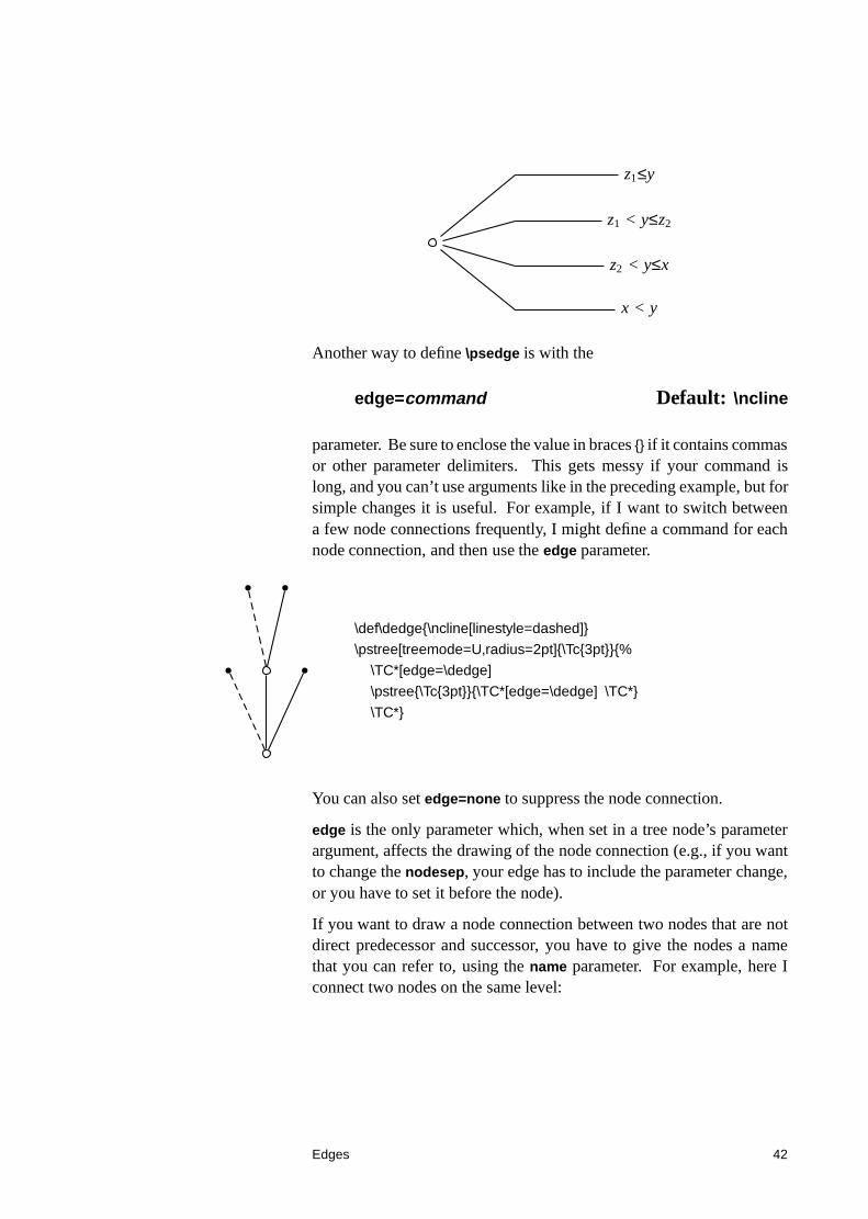
Here is another example with \ncdiagg. Note the use of negative thearmA value so that the corners of the edges are vertically aligned, eventhough the nodes have different sizes:
$
\def\psedge#1#2{\ncdiagg[angleA=180, armA=-3cm,
nodesep=4pt]{#2}{#1}}
% Or: \renewcommand{\psedge}[2]{ ... }
\pstree[treemode=R, levelsep=5cm]{\Tc{3pt}}{%
\Tr{z_1\leq y}
\Tr{z_1<y\leq z_2}
\Tr{z_2<y\leq x}
\Tr{x<y}}
$
Edges 41
z1≤y
z1 < y≤z2
z2 < y≤x
x < y
Another way to define \psedge is with the
edge=command Default: \ncline
parameter. Be sure to enclose the value in braces {} if it contains commasor other parameter delimiters. This gets messy if your command islong, and you can’t use arguments like in the preceding example, but forsimple changes it is useful. For example, if I want to switch betweena few node connections frequently, I might define a command for eachnode connection, and then use the edge parameter.
\def\dedge{\ncline[linestyle=dashed]}
\pstree[treemode=U,radius=2pt]{\Tc{3pt}}{%
\TC*[edge=\dedge]
\pstree{\Tc{3pt}}{\TC*[edge=\dedge] \TC*}
\TC*}
You can also set edge=none to suppress the node connection.
edge is the only parameter which, when set in a tree node’s parameterargument, affects the drawing of the node connection (e.g., if you wantto change the nodesep, your edge has to include the parameter change,or you have to set it before the node).
If you want to draw a node connection between two nodes that are notdirect predecessor and successor, you have to give the nodes a namethat you can refer to, using the name parameter. For example, here Iconnect two nodes on the same level:
Edges 42
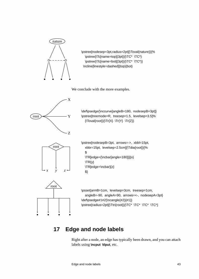
nature
\pstree[nodesep=3pt,radius=2pt]{\Toval{nature}}{%
\pstree{\Tc[name=top]{3pt}}{\TC* \TC*}
\pstree{\Tc[name=bot]{3pt}}{\TC* \TC*}}
\ncline[linestyle=dashed]{top}{bot}
We conclude with the more examples.
root
X
Y
Z
\def\psedge{\nccurve[angleB=180, nodesepB=3pt]}
\pstree[treemode=R, treesep=1.5, levelsep=3.5]%
{\Toval{root}}{\Tr{X} \Tr{Y} \Tr{Z}}
root
x y z
\pstree[nodesepB=3pt, arrows=->, xbbl=15pt,
xbbr=15pt, levelsep=2.5cm]{\Tdia{root}}{%
$
\TR[edge={\ncbar[angle=180]}]{x}
\TR{y}
\TR[edge=\ncbar]{z}
$}
root\psset{armB=1cm, levelsep=3cm, treesep=1cm,
angleB=-90, angleA=90, arrows=<-, nodesepA=3pt}
\def\psedge#1#2{\ncangle{#2}{#1}}
\pstree[radius=2pt]{\Ttri{root}}{\TC* \TC* \TC* \TC*}
17 Edge and node labels
Right after a node, an edge has typically been drawn, and you can attachlabels using \ncput \tlput, etc.
Edge and node labels 43
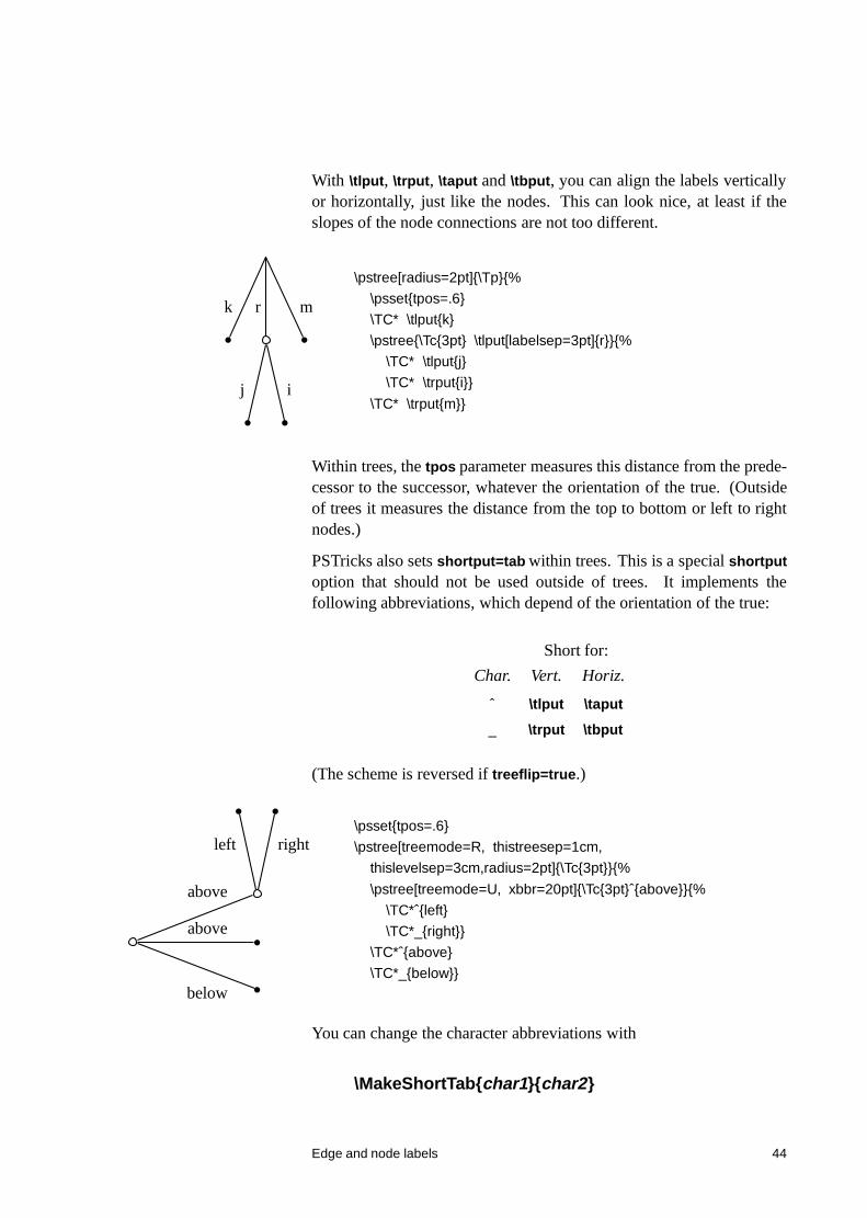
With \tlput, \trput, \taput and \tbput, you can align the labels verticallyor horizontally, just like the nodes. This can look nice, at least if theslopes of the node connections are not too different.
k r
j i
m
\pstree[radius=2pt]{\Tp}{%
\psset{tpos=.6}
\TC* \tlput{k}
\pstree{\Tc{3pt} \tlput[labelsep=3pt]{r}}{%
\TC* \tlput{j}
\TC* \trput{i}}
\TC* \trput{m}}
Within trees, the tpos parameter measures this distance from the prede-cessor to the successor, whatever the orientation of the true. (Outsideof trees it measures the distance from the top to bottom or left to rightnodes.)
PSTricks also sets shortput=tab within trees. This is a special shortputoption that should not be used outside of trees. It implements thefollowing abbreviations, which depend of the orientation of the true:
Short for:
Char. Vert. Horiz.
ˆ \tlput \taput
_ \trput \tbput
(The scheme is reversed if treeflip=true.)
above
left right
above
below
\psset{tpos=.6}
\pstree[treemode=R, thistreesep=1cm,
thislevelsep=3cm,radius=2pt]{\Tc{3pt}}{%
\pstree[treemode=U, xbbr=20pt]{\Tc{3pt}ˆ{above}}{%
\TC*ˆ{left}
\TC*_{right}}
\TC*ˆ{above}
\TC*_{below}}
You can change the character abbreviations with
\MakeShortTab{char1}{char2}
Edge and node labels 44
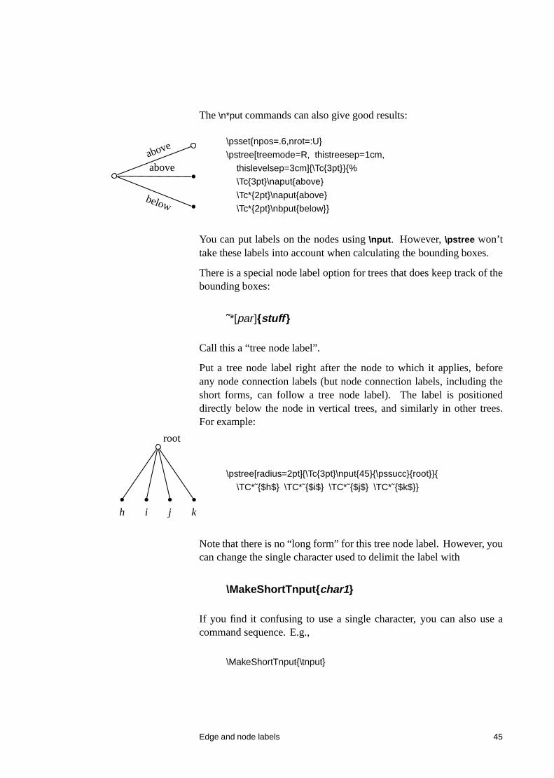
The \n*put commands can also give good results:
above
above
below
\psset{npos=.6,nrot=:U}
\pstree[treemode=R, thistreesep=1cm,
thislevelsep=3cm]{\Tc{3pt}}{%
\Tc{3pt}\naput{above}
\Tc*{2pt}\naput{above}
\Tc*{2pt}\nbput{below}}
You can put labels on the nodes using \nput. However, \pstree won’ttake these labels into account when calculating the bounding boxes.
There is a special node label option for trees that does keep track of thebounding boxes:
˜*[par]{stuff }
Call this a “tree node label”.
Put a tree node label right after the node to which it applies, beforeany node connection labels (but node connection labels, including theshort forms, can follow a tree node label). The label is positioneddirectly below the node in vertical trees, and similarly in other trees.For example:
root
h i j k
\pstree[radius=2pt]{\Tc{3pt}\nput{45}{\pssucc}{root}}{
\TC*˜{$h$} \TC*˜{$i$} \TC*˜{$j$} \TC*˜{$k$}}
Note that there is no “long form” for this tree node label. However, youcan change the single character used to delimit the label with
\MakeShortTnput{char1}
If you find it confusing to use a single character, you can also use acommand sequence. E.g.,
\MakeShortTnput{\tnput}
Edge and node labels 45
You can have multiple labels, but each successive label is positionedrelative to the bounding box that includes the previous labels. Thus,the order in which the labels are placed makes a difference, and not allcombinations will produce satisfactory results.
You will probably find that the tree node label works well for terminalnodes, without your intervention. However, you can control the treenode labels be setting several parameters.
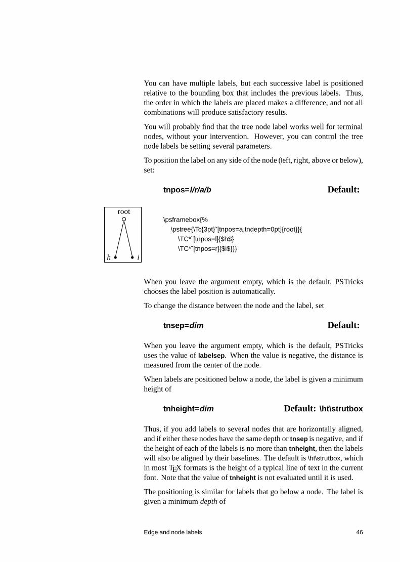
To position the label on any side of the node (left, right, above or below),set:
tnpos=l/r/a/b Default:
root
h i
\psframebox{%
\pstree{\Tc{3pt}˜[tnpos=a,tndepth=0pt]{root}}{
\TC*˜[tnpos=l]{$h$}
\TC*˜[tnpos=r]{$i$}}}
When you leave the argument empty, which is the default, PSTrickschooses the label position is automatically.
To change the distance between the node and the label, set
tnsep=dim Default:
When you leave the argument empty, which is the default, PSTricksuses the value of labelsep. When the value is negative, the distance ismeasured from the center of the node.
When labels are positioned below a node, the label is given a minimumheight of
tnheight=dim Default: \ht\strutbox
Thus, if you add labels to several nodes that are horizontally aligned,and if either these nodes have the same depth or tnsep is negative, and ifthe height of each of the labels is no more than tnheight, then the labelswill also be aligned by their baselines. The default is \ht\strutbox, whichin most TEX formats is the height of a typical line of text in the currentfont. Note that the value of tnheight is not evaluated until it is used.
The positioning is similar for labels that go below a node. The label isgiven a minimum depth of
Edge and node labels 46
tndepth=dim Default: \dp\strutbox
For labels positioned above or below, the horizontal reference point ofthe label, i.e., the point in the label directly above or below the centerof the node, is set by the href parameter.
When labels are positioned on the left or right, the right or left edge ofthe label is positioned distance tnsep from the node. The vertical pointthat is aligned with the center of the node is set by
tnyref=num Default:
When you leave this empty, vref is used instead. Recall that vref givesthe vertical distance from the baseline. Otherwise, the tnyref parameterworks like the yref parameter, giving the fraction of the distance fromthe bottom to the top of the label.
18 Details
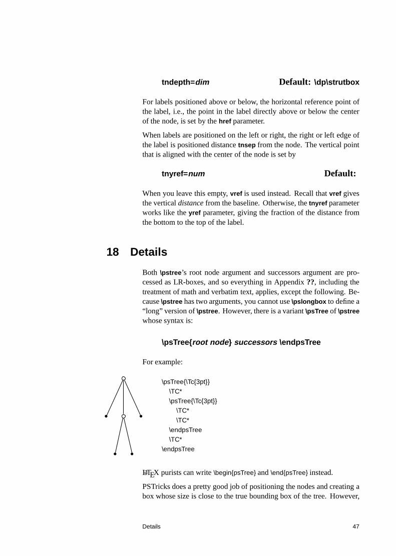
Both \pstree’s root node argument and successors argument are pro-cessed as LR-boxes, and so everything in Appendix ??, including thetreatment of math and verbatim text, applies, except the following. Be-cause \pstree has two arguments, you cannot use \pslongbox to define a“long” version of \pstree. However, there is a variant \psTree of \pstreewhose syntax is:
\psTree{root node} successors \endpsTree
For example:
\psTree{\Tc{3pt}}
\TC*
\psTree{\Tc{3pt}}
\TC*
\TC*
\endpsTree
\TC*
\endpsTree
LaTEX purists can write \begin{psTree} and \end{psTree} instead.
PSTricks does a pretty good job of positioning the nodes and creating abox whose size is close to the true bounding box of the tree. However,
Details 47
PSTricks does not take into account the node connections or labels whencalculating the bounding boxes, except the tree node labels.
If, for this or other reasons, you want to fine tune the bounding box ofthe nodes, you can set the following parameters:
bbl=dim Default:bbr=dim Default:bbh=dim Default:bbd=dim Default:xbbl=dim Default:xbbr=dim Default:xbbh=dim Default:xbbd=dim Default:
The x versions increase the bounding box by dim, and the others set thebounding box to dim. There is one parameter for each direction fromthe center of the node, left, right, height, and depth.
These parameters affect trees and nodes, and subtrees that switch direc-tions, but not subtrees that go in the same direction as their parent tree(such subtrees have a profile rather than a bounding box, and should beadjusted by changing the bounding boxes of the constituent nodes).
Save any fiddling with the bounding box until you are otherwise finishedwith the tree.
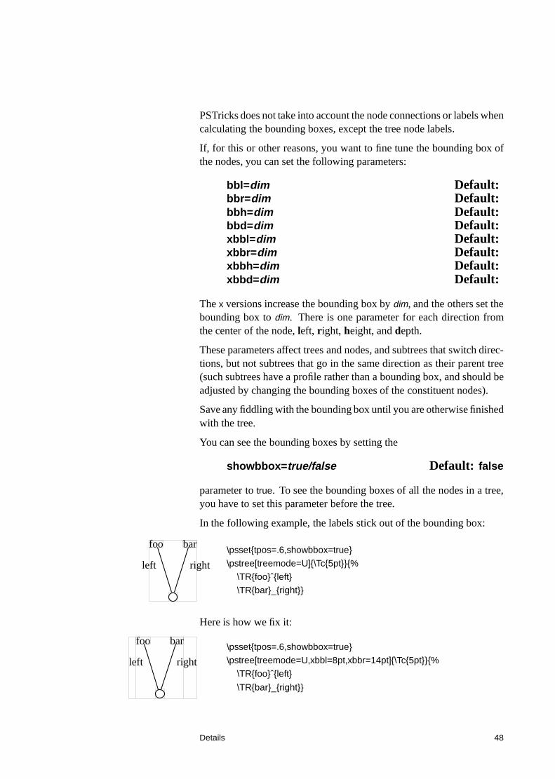
You can see the bounding boxes by setting the
showbbox=true/false Default: false
parameter to true. To see the bounding boxes of all the nodes in a tree,you have to set this parameter before the tree.
In the following example, the labels stick out of the bounding box:
foo
left
bar
right
\psset{tpos=.6,showbbox=true}
\pstree[treemode=U]{\Tc{5pt}}{%
\TR{foo}ˆ{left}
\TR{bar}_{right}}
Here is how we fix it:
foo
left
bar
right
\psset{tpos=.6,showbbox=true}
\pstree[treemode=U,xbbl=8pt,xbbr=14pt]{\Tc{5pt}}{%
\TR{foo}ˆ{left}
\TR{bar}_{right}}
Details 48
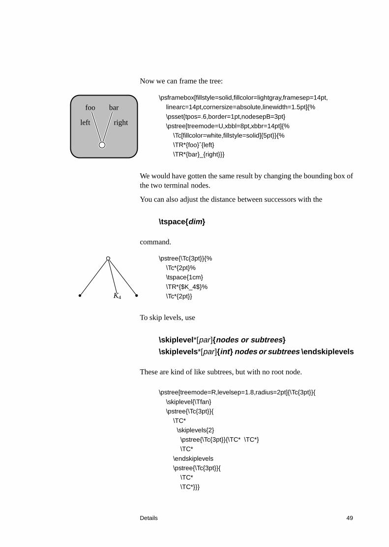
Now we can frame the tree:
foo
left
bar
right
\psframebox[fillstyle=solid,fillcolor=lightgray,framesep=14pt,
linearc=14pt,cornersize=absolute,linewidth=1.5pt]{%
\psset{tpos=.6,border=1pt,nodesepB=3pt}
\pstree[treemode=U,xbbl=8pt,xbbr=14pt]{%
\Tc[fillcolor=white,fillstyle=solid]{5pt}}{%
\TR*{foo}ˆ{left}
\TR*{bar}_{right}}}
We would have gotten the same result by changing the bounding box ofthe two terminal nodes.
You can also adjust the distance between successors with the
\tspace{dim}
command.
K4
\pstree{\Tc{3pt}}{%
\Tc*{2pt}%
\tspace{1cm}
\TR*{$K_4$}%
\Tc*{2pt}}
To skip levels, use
\skiplevel*[par]{nodes or subtrees}
\skiplevels*[par]{int} nodes or subtrees \endskiplevels
These are kind of like subtrees, but with no root node.
\pstree[treemode=R,levelsep=1.8,radius=2pt]{\Tc{3pt}}{
\skiplevel{\Tfan}
\pstree{\Tc{3pt}}{
\TC*
\skiplevels{2}
\pstree{\Tc{3pt}}{\TC* \TC*}
\TC*
\endskiplevels
\pstree{\Tc{3pt}}{
\TC*
\TC*}}}
Details 49
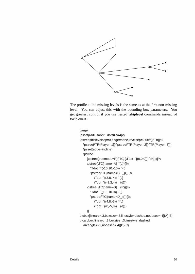
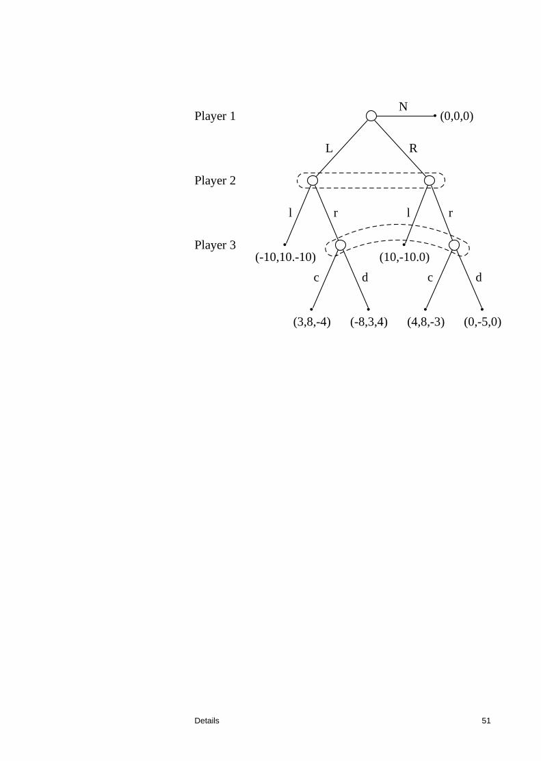
The profile at the missing levels is the same as at the first non-missinglevel. You can adjust this with the bounding box parameters. Youget greatest control if you use nested \skiplevel commands instead of\skiplevels.
\large
\psset{radius=6pt, dotsize=4pt}
\pstree[thislevelsep=0,edge=none,levelsep=2.5cm]{\Tn}{%
\pstree{\TR{Player 1}}{\pstree{\TR{Player 2}}{\TR{Player 3}}}
\psset{edge=\ncline}
\pstree
{\pstree[treemode=R]{\TC}{\Tdot ˜{(0,0,0)} ˆ{N}}}{%
\pstree{\TC[name=A] ˆ{L}}{%
\Tdot ˜{(-10,10.-10)} ˆ{l}
\pstree{\TC[name=C] _{r}}{%
\Tdot ˜{(3,8,-4)} ˆ{c}
\Tdot ˜{(-8,3,4)} _{d}}}
\pstree{\TC[name=B] _{R}}{%
\Tdot ˜{(10,-10.0)} ˆ{l}
\pstree{\TC[name=D]_{r}}{%
\Tdot ˜{(4,8,-3)} ˆ{c}
\Tdot ˜{(0,-5,0)} _{d}}}
}}
\ncbox[linearc=.3,boxsize=.3,linestyle=dashed,nodesep=.4]{A}{B}
\ncarcbox[linearc=.3,boxsize=.3,linestyle=dashed,
arcangle=25,nodesep=.4]{D}{C}
Details 50
Player 1
Player 2
Player 3
• (0,0,0)N
L
•(-10,10.-10)
l r
•(3,8,-4)
c
•(-8,3,4)
d
R
•(10,-10.0)
l r
•(4,8,-3)
c
•(0,-5,0)
d
Details 51

![Preparing Slides Using LaTeX, Pstricks, and Beameruday/latex/making-slides.pdf · \titlegraphic{\scalebox{.4}{\includegraphics{IITBlogo.epsi}}} \date[Prabhat Workshop]{August 2010}](https://img.pdfslide.us/doc/110x75/5f0ffa0f7e708231d446d3ad/preparing-slides-using-latex-pstricks-and-beamer-udaylatexmaking-titlegraphicscalebox4includegraphicsiitblogoepsi.jpg)