Embed Size (px)
Citation preview
Registered charity number: 207890
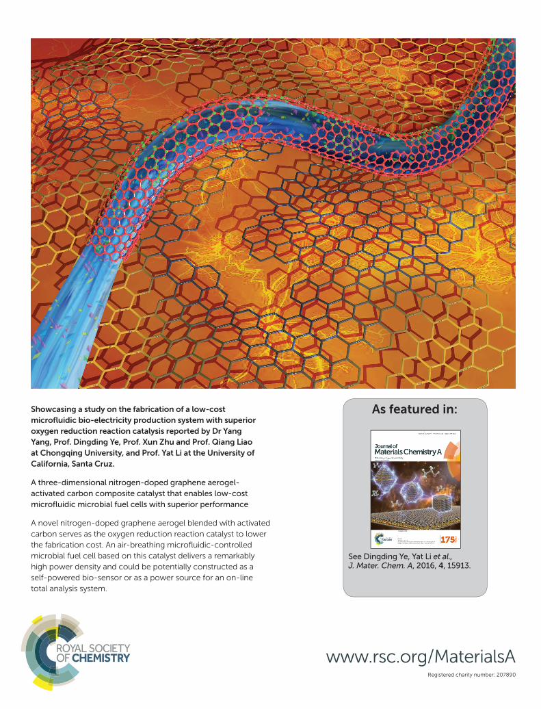
Showcasing a study on the fabrication of a low-cost
microfl uidic bio-electricity production system with superior
oxygen reduction reaction catalysis reported by Dr Yang
Yang, Prof. Dingding Ye, Prof. Xun Zhu and Prof. Qiang Liao
at Chongqing University, and Prof. Yat Li at the University of
California, Santa Cruz.
A three-dimensional nitrogen-doped graphene aerogel-
activated carbon composite catalyst that enables low-cost
microfl uidic microbial fuel cells with superior performance
A novel nitrogen-doped graphene aerogel blended with activated
carbon serves as the oxygen reduction reaction catalyst to lower
the fabrication cost. An air-breathing microfl uidic-controlled
microbial fuel cell based on this catalyst delivers a remarkably
high power density and could be potentially constructed as a
self-powered bio-sensor or as a power source for an on-line
total analysis system.
As featured in:
See Dingding Ye, Yat Li et al., J. Mater. Chem. A, 2016, 4, 15913.
www.rsc.org/MaterialsA
Journal ofMaterials Chemistry A
PAPER
Publ
ishe
d on
10
Aug
ust 2
016.
Dow
nloa
ded
by U
nive
rsity
of
Cal
ifor
nia
- Sa
nta
Cru
z on
21/
10/2
016
21:2
0:44
.
View Article OnlineView Journal | View Issue
A three-dimensio
aKey Laboratory of Low-grade Energy Utilizat
University), Ministry of Education, Cho
[email protected] of Chemistry and Biochemistr
California 95060, USA. E-mail: [email protected]
† Electronic supplementary informa10.1039/c6ta05002f
Cite this: J. Mater. Chem. A, 2016, 4,15913
Received 15th June 2016Accepted 10th August 2016
DOI: 10.1039/c6ta05002f
www.rsc.org/MaterialsA
This journal is © The Royal Society of C
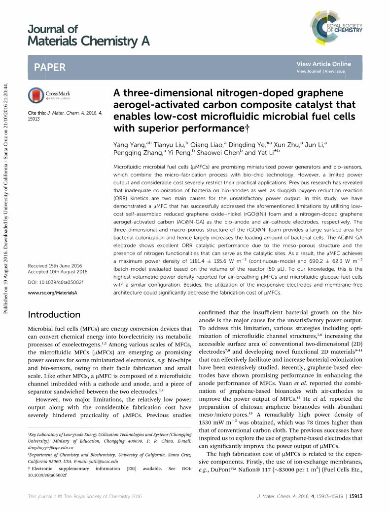
nal nitrogen-doped grapheneaerogel-activated carbon composite catalyst thatenables low-cost microfluidic microbial fuel cellswith superior performance†
Yang Yang,ab Tianyu Liu,b Qiang Liao,a Dingding Ye,*a Xun Zhu,a Jun Li,a
Pengqing Zhang,a Yi Peng,b Shaowei Chenb and Yat Li*b
Microfluidic microbial fuel cells (mMFCs) are promising miniaturized power generators and bio-sensors,
which combine the micro-fabrication process with bio-chip technology. However, a limited power
output and considerable cost severely restrict their practical applications. Previous research has revealed
that inadequate colonization of bacteria on bio-anodes as well as sluggish oxygen reduction reaction
(ORR) kinetics are two main causes for the unsatisfactory power output. In this study, we have
demonstrated a mMFC that has successfully addressed the aforementioned limitations by utilizing low-
cost self-assembled reduced graphene oxide–nickel (rGO@Ni) foam and a nitrogen-doped graphene
aerogel-activated carbon (AC@N-GA) as the bio-anode and air-cathode electrodes, respectively. The
three-dimensional and macro-porous structure of the rGO@Ni foam provides a large surface area for
bacterial colonization and hence largely increases the loading amount of bacterial cells. The AC@N-GA
electrode shows excellent ORR catalytic performance due to the meso-porous structure and the
presence of nitrogen functionalities that can serve as the catalytic sites. As a result, the mMFC achieves
a maximum power density of 1181.4 � 135.6 W m�3 (continuous-mode) and 690.2 � 62.3 W m�3
(batch-mode) evaluated based on the volume of the reactor (50 mL). To our knowledge, this is the
highest volumetric power density reported for air-breathing mMFCs and microfluidic glucose fuel cells
with a similar configuration. Besides, the utilization of the inexpensive electrodes and membrane-free
architecture could significantly decrease the fabrication cost of mMFCs.
Introduction
Microbial fuel cells (MFCs) are energy conversion devices thatcan convert chemical energy into bio-electricity via metabolicprocesses of exoelectrogens.1,2 Among various scales of MFCs,the microuidic MFCs (mMFCs) are emerging as promisingpower sources for some miniaturized electronics, e.g. bio-chipsand bio-sensors, owing to their facile fabrication and smallscale. Like other MFCs, a mMFC is composed of a microuidicchannel imbedded with a cathode and anode, and a piece ofseparator sandwiched between the two electrodes.3,4
However, two major limitations, the relatively low poweroutput along with the considerable fabrication cost haveseverely hindered practicality of mMFCs. Previous studies
ion Technologies and Systems (Chongqing
ngqing 400030, P. R. China. E-mail:
y, University of California, Santa Cruz,
du
tion (ESI) available. See DOI:
hemistry 2016
conrmed that the insufficient bacterial growth on the bio-anode is the major cause for the unsatisfactory power output.To address this limitation, various strategies including opti-mization of microuidic channel structures,5,6 increasing theaccessible surface area of conventional two-dimensional (2D)electrodes7,8 and developing novel functional 2D materials9–11
that can effectively facilitate and increase bacterial colonizationhave been extensively studied. Recently, graphene-based elec-trodes have shown promising performance in enhancing theanode performance of MFCs. Yuan et al. reported the combi-nation of graphene-based bioanodes with air-cathodes toimprove the power output of MFCs.12 He et al. reported thepreparation of chitosan–graphene bioanodes with abundantmeso-/micro-pores.13 A remarkably high power density of1530 mW m�2 was obtained, which was 78 times higher thanthat of conventional carbon cloth. The previous successes haveinspired us to explore the use of graphene-based electrodes thatcan signicantly improve the power output of mMFCs.
The high fabrication cost of mMFCs is related to the expen-sive components. Firstly, the use of ion-exchange membranes,e.g., DuPont™ Naon® 117 (�$3000 per 1 m2) (Fuel Cells Etc.,
J. Mater. Chem. A, 2016, 4, 15913–15919 | 15913
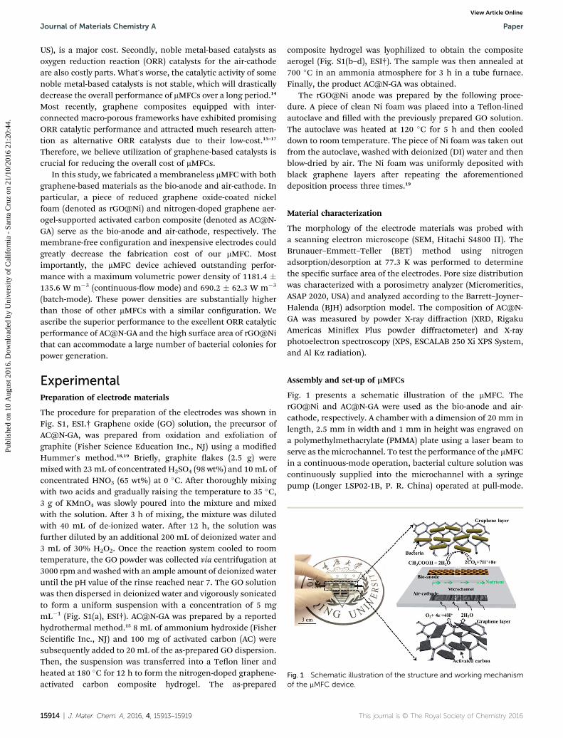
Fig. 1 Schematic illustration of the structure and working mechanismof the mMFC device.
Journal of Materials Chemistry A Paper
Publ
ishe
d on
10
Aug
ust 2
016.
Dow
nloa
ded
by U
nive
rsity
of
Cal
ifor
nia
- Sa
nta
Cru
z on
21/
10/2
016
21:2
0:44
. View Article Online
US), is a major cost. Secondly, noble metal-based catalysts asoxygen reduction reaction (ORR) catalysts for the air-cathodeare also costly parts. What's worse, the catalytic activity of somenoble metal-based catalysts is not stable, which will drasticallydecrease the overall performance of mMFCs over a long period.14
Most recently, graphene composites equipped with inter-connected macro-porous frameworks have exhibited promisingORR catalytic performance and attracted much research atten-tion as alternative ORR catalysts due to their low-cost.15–17
Therefore, we believe utilization of graphene-based catalysts iscrucial for reducing the overall cost of mMFCs.
In this study, we fabricated a membraneless mMFC with bothgraphene-based materials as the bio-anode and air-cathode. Inparticular, a piece of reduced graphene oxide-coated nickelfoam (denoted as rGO@Ni) and nitrogen-doped graphene aer-ogel-supported activated carbon composite (denoted as AC@N-GA) serve as the bio-anode and air-cathode, respectively. Themembrane-free conguration and inexpensive electrodes couldgreatly decrease the fabrication cost of our mMFC. Mostimportantly, the mMFC device achieved outstanding perfor-mance with a maximum volumetric power density of 1181.4 �135.6 W m�3 (continuous-ow mode) and 690.2 � 62.3 W m�3
(batch-mode). These power densities are substantially higherthan those of other mMFCs with a similar conguration. Weascribe the superior performance to the excellent ORR catalyticperformance of AC@N-GA and the high surface area of rGO@Nithat can accommodate a large number of bacterial colonies forpower generation.
ExperimentalPreparation of electrode materials
The procedure for preparation of the electrodes was shown inFig. S1, ESI.† Graphene oxide (GO) solution, the precursor ofAC@N-GA, was prepared from oxidation and exfoliation ofgraphite (Fisher Science Education Inc., NJ) using a modiedHummer's method.18,19 Briey, graphite akes (2.5 g) weremixed with 23 mL of concentrated H2SO4 (98 wt%) and 10 mL ofconcentrated HNO3 (65 wt%) at 0 �C. Aer thoroughly mixingwith two acids and gradually raising the temperature to 35 �C,3 g of KMnO4 was slowly poured into the mixture and mixedwith the solution. Aer 3 h of mixing, the mixture was dilutedwith 40 mL of de-ionized water. Aer 12 h, the solution wasfurther diluted by an additional 200 mL of deionized water and3 mL of 30% H2O2. Once the reaction system cooled to roomtemperature, the GO powder was collected via centrifugation at3000 rpm and washed with an ample amount of deionized wateruntil the pH value of the rinse reached near 7. The GO solutionwas then dispersed in deionized water and vigorously sonicatedto form a uniform suspension with a concentration of 5 mgmL�1 (Fig. S1(a), ESI†). AC@N-GA was prepared by a reportedhydrothermal method.15 8 mL of ammonium hydroxide (FisherScientic Inc., NJ) and 100 mg of activated carbon (AC) weresubsequently added to 20 mL of the as-prepared GO dispersion.Then, the suspension was transferred into a Teon liner andheated at 180 �C for 12 h to form the nitrogen-doped graphene-activated carbon composite hydrogel. The as-prepared
15914 | J. Mater. Chem. A, 2016, 4, 15913–15919
composite hydrogel was lyophilized to obtain the compositeaerogel (Fig. S1(b–d), ESI†). The sample was then annealed at700 �C in an ammonia atmosphere for 3 h in a tube furnace.Finally, the product AC@N-GA was obtained.
The rGO@Ni anode was prepared by the following proce-dure. A piece of clean Ni foam was placed into a Teon-linedautoclave and lled with the previously prepared GO solution.The autoclave was heated at 120 �C for 5 h and then cooleddown to room temperature. The piece of Ni foam was taken outfrom the autoclave, washed with deionized (DI) water and thenblow-dried by air. The Ni foam was uniformly deposited withblack graphene layers aer repeating the aforementioneddeposition process three times.19
Material characterization
The morphology of the electrode materials was probed witha scanning electron microscope (SEM, Hitachi S4800 P). TheBrunauer–Emmett–Teller (BET) method using nitrogenadsorption/desorption at 77.3 K was performed to determinethe specic surface area of the electrodes. Pore size distributionwas characterized with a porosimetry analyzer (Micromeritics,ASAP 2020, USA) and analyzed according to the Barrett–Joyner–Halenda (BJH) adsorption model. The composition of AC@N-GA was measured by powder X-ray diffraction (XRD, RigakuAmericas Miniex Plus powder diffractometer) and X-rayphotoelectron spectroscopy (XPS, ESCALAB 250 Xi XPS System,and Al Ka radiation).
Assembly and set-up of mMFCs
Fig. 1 presents a schematic illustration of the mMFC. TherGO@Ni and AC@N-GA were used as the bio-anode and air-cathode, respectively. A chamber with a dimension of 20 mm inlength, 2.5 mm in width and 1 mm in height was engraved ona polymethylmethacrylate (PMMA) plate using a laser beam toserve as the microchannel. To test the performance of the mMFCin a continuous-mode operation, bacterial culture solution wascontinuously supplied into the microchannel with a syringepump (Longer LSP02-1B, P. R. China) operated at pull-mode.
This journal is © The Royal Society of Chemistry 2016
Paper Journal of Materials Chemistry A
Publ
ishe
d on
10
Aug
ust 2
016.
Dow
nloa
ded
by U
nive
rsity
of
Cal
ifor
nia
- Sa
nta
Cru
z on
21/
10/2
016
21:2
0:44
. View Article Online
Such a conguration enables a strong negative pressure insideof the mMFC that simultaneously sucks in oxygen gas andprevents leakage,20 which does not need the help of the poly-tetrauoroethylene layer. For the batch-mode operation, themMFC was operated for 12 h in a cycle, and the entire electrolytewas replenished with fresh bacterial culture solution prior toanother cycle. An Ag/AgCl (saturated KCl solution, +0.197 V vs.standard hydrogen electrode) was used as a reference electrode.All the experiments were carried out under ambient pressureand room temperature.
The mMFC was inoculated with anaerobic digester sludgecontaining exoelectrogenic bacteria. During the inoculationprocess, an external resistor of 5000 U was connected in serieswith the mMFC. The output voltage (V) across the externalresistor was recorded using a digital multimeter (Model 34070A,Agilent Technologies Inc., CA). Once a fast voltage-increase wasobserved, a fresh medium containing 3.39 g L�1 of sodiumacetate (nutrients for bacteria), various inorganic salts (trace-elements for bacterial growth)21 and phosphate buffer solution(18.2 g K2HPO4 and 2.45 g KH2PO4 dissolved in 1 L of deionizedwater) were injected to the microchannel.
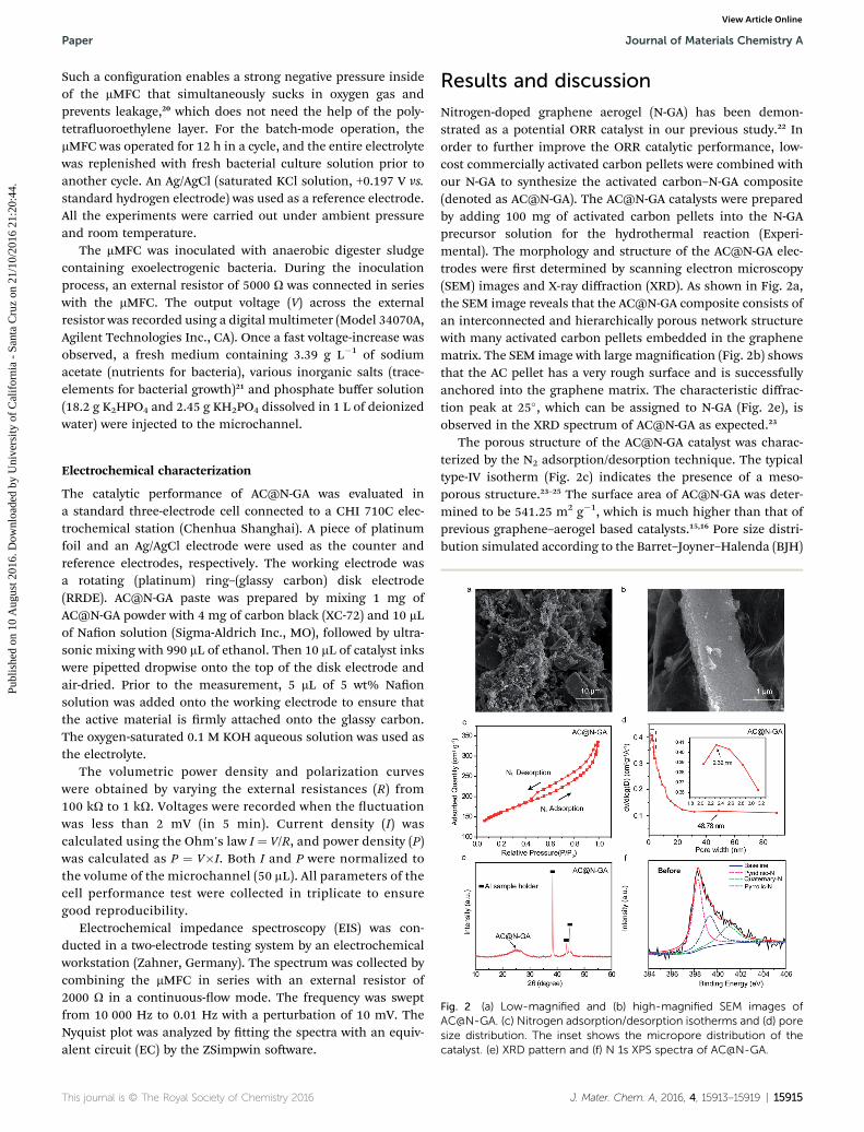
Fig. 2 (a) Low-magnified and (b) high-magnified SEM images ofAC@N-GA. (c) Nitrogen adsorption/desorption isotherms and (d) poresize distribution. The inset shows the micropore distribution of thecatalyst. (e) XRD pattern and (f) N 1s XPS spectra of AC@N-GA.
Electrochemical characterization
The catalytic performance of AC@N-GA was evaluated ina standard three-electrode cell connected to a CHI 710C elec-trochemical station (Chenhua Shanghai). A piece of platinumfoil and an Ag/AgCl electrode were used as the counter andreference electrodes, respectively. The working electrode wasa rotating (platinum) ring–(glassy carbon) disk electrode(RRDE). AC@N-GA paste was prepared by mixing 1 mg ofAC@N-GA powder with 4 mg of carbon black (XC-72) and 10 mLof Naon solution (Sigma-Aldrich Inc., MO), followed by ultra-sonic mixing with 990 mL of ethanol. Then 10 mL of catalyst inkswere pipetted dropwise onto the top of the disk electrode andair-dried. Prior to the measurement, 5 mL of 5 wt% Naonsolution was added onto the working electrode to ensure thatthe active material is rmly attached onto the glassy carbon.The oxygen-saturated 0.1 M KOH aqueous solution was used asthe electrolyte.
The volumetric power density and polarization curveswere obtained by varying the external resistances (R) from100 kU to 1 kU. Voltages were recorded when the uctuationwas less than 2 mV (in 5 min). Current density (I) wascalculated using the Ohm's law I ¼ V/R, and power density (P)was calculated as P ¼ V�I. Both I and P were normalized tothe volume of the microchannel (50 mL). All parameters of thecell performance test were collected in triplicate to ensuregood reproducibility.
Electrochemical impedance spectroscopy (EIS) was con-ducted in a two-electrode testing system by an electrochemicalworkstation (Zahner, Germany). The spectrum was collected bycombining the mMFC in series with an external resistor of2000 U in a continuous-ow mode. The frequency was sweptfrom 10 000 Hz to 0.01 Hz with a perturbation of 10 mV. TheNyquist plot was analyzed by tting the spectra with an equiv-alent circuit (EC) by the ZSimpwin soware.
This journal is © The Royal Society of Chemistry 2016
Results and discussion
Nitrogen-doped graphene aerogel (N-GA) has been demon-strated as a potential ORR catalyst in our previous study.22 Inorder to further improve the ORR catalytic performance, low-cost commercially activated carbon pellets were combined withour N-GA to synthesize the activated carbon–N-GA composite(denoted as AC@N-GA). The AC@N-GA catalysts were preparedby adding 100 mg of activated carbon pellets into the N-GAprecursor solution for the hydrothermal reaction (Experi-mental). The morphology and structure of the AC@N-GA elec-trodes were rst determined by scanning electron microscopy(SEM) images and X-ray diffraction (XRD). As shown in Fig. 2a,the SEM image reveals that the AC@N-GA composite consists ofan interconnected and hierarchically porous network structurewith many activated carbon pellets embedded in the graphenematrix. The SEM image with large magnication (Fig. 2b) showsthat the AC pellet has a very rough surface and is successfullyanchored into the graphene matrix. The characteristic diffrac-tion peak at 25�, which can be assigned to N-GA (Fig. 2e), isobserved in the XRD spectrum of AC@N-GA as expected.23
The porous structure of the AC@N-GA catalyst was charac-terized by the N2 adsorption/desorption technique. The typicaltype-IV isotherm (Fig. 2c) indicates the presence of a meso-porous structure.23–25 The surface area of AC@N-GA was deter-mined to be 541.25 m2 g�1, which is much higher than that ofprevious graphene–aerogel based catalysts.15,16 Pore size distri-bution simulated according to the Barret–Joyner–Halenda (BJH)
J. Mater. Chem. A, 2016, 4, 15913–15919 | 15915
Journal of Materials Chemistry A Paper
Publ
ishe
d on
10
Aug
ust 2
016.
Dow
nloa
ded
by U
nive
rsity
of
Cal
ifor
nia
- Sa
nta
Cru
z on
21/
10/2
016
21:2
0:44
. View Article Online
adsorption model is depicted in Fig. 2d. Clearly, the AC@N-GAcatalyst contains micro-pores with a dominating pore width ofaround 2.32 nm, possibly from themicroporous structure of AC.Altogether, AC@N-GA is a three-dimensional catalyst full ofmesopores and micropores. Furthermore, X-ray photoelectricspectroscopy (XPS) (Fig. 2f and S2 in the ESI†) shows that thenitrogen content of AC@N-GA is 5.2%. The high-resolution N 1speak (Fig. 2f) can be de-convoluted into several synthetic peaksassociated with pyridinic-N (398.5 eV), pyrrolic-N (400.1 eV) andquarternary-N (400.8 eV).26 The existence of these N-functionalgroups is benecial for achieving excellent catalytic perfor-mance, which will be discussed in the following section.
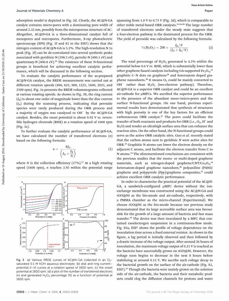
To evaluate the catalytic performance of the as-preparedAC@N-GA catalyst, the RRDE measurement was carried out atdifferent rotation speeds (400, 625, 900, 1225, 1600, 2025, and2500 rpm). Fig. 3a presents the RRDE voltammograms collectedat various rotating speeds. As shown in Fig. 3b, the ring current(IR) is about one order of magnitude lower than the disc current(ID) during the scanning process, indicating that peroxidespecies were rarely produced during the ORR process anda majority of oxygen was catalyzed to OH� by the AC@N-GAcatalyst. Besides, the onset potential is about 0.92 V vs. revers-ible hydrogen electrode (RHE) at a rotation speed of 1600 rpm(Fig. 3c).
To further evaluate the catalytic performance of AC@N-GA,we have calculated the number of transferred electrons (n)based on the following formula:
n ¼ 4ID�ID þ IR
N
� (1)
where N is the collection efficiency (37%).27 At a high rotatingspeed (1600 rpm), n reaches 3.95 within the potential range
Fig. 3 (a) Various RRDE curves of AC@N-GA collected in an O2-saturated 0.1 M KOH aqueous electrolyte; (b) disk and ring current–potential (I–V) curves at a rotation speed of 1600 rpm; (c) the onsetpotential at 1600 rpm; (d) a plot of the number of transferred electrons(n) and generated H2O2 percentage (%) as a function of potential at1600 rpm.
15916 | J. Mater. Chem. A, 2016, 4, 15913–15919
spanning from 1.0 V to 0.75 V (Fig. 3d), which is comparable toother noble metal-based ORR catalysts.15,16,28 The large numberof transferred electrons under the steady state suggests thata four-electron pathway is the dominated process for the ORR.The yield of peroxide was calculated by the following formula:
%ðH2O2Þ ¼ 200� IR=N
ðID þ IR=NÞ (2)
The total percentage of H2O2 generated is 4.5% within thepotential below 0.6 V vs. RHE, which is substantially lower thanother graphene-based catalysts including GA-supported Fe3O4,15
graphitic C–N dots on graphene29 and heteroatom doped gra-phene nanosheets.30 It means O2 could be mainly converted toOH� rather than H2O2 (two-electron pathway). Therefore,AC@N-GA is a superior ORR catalyst and could be an excellentair-cathode for mMFCs. We ascribed the superior performanceto the presence of the abundant meso-/micro-pores and thesurface N-functional groups. On one hand, previous experi-mental results have demonstrated that synthesis of structureswith high porosity is one of the key factors for an efficientcarbonaceous ORR catalyst.31 The pores could facilitate thetransfer of both reactants and products for ORR (i.e., O2, H
+ andH2O) and render an ultrahigh surface area that can enhance thereaction sites. On the other hand, the N-functional groups couldserve as the active ORR catalytic sites. Guo et al. recently statedthat the carbon atoms next to pyridinic N were active sites forORR.32 Graphitic N atoms can lower the electron density on theadjacent C atoms, and facilitate the electron transfer from C toN atoms.33 The aforementioned conclusions are consistent withthe previous studies that the mono- or multi-doped graphenematerials, such as nitrogen-doped graphene/CNT/Co3O4,34
heteroatom-doped graphene nanosheet,30 polyaniline (PANI)/graphene and polypyrrole (Ppy)/graphene composites,33 couldachieve excellent ORR catalytic performance.
In order to characterize the practical potential of the AC@N-GA, a sandwich-congured mMFC device without the ion-exchange membrane was constructed using the AC@N-GA andrGO@Ni as the bio-anode and air-cathode, respectively, witha PMMA chamber as the micro-channel (Experimental). Wechoose rGO@Ni as the bio-anode because our previous studydemonstrated that its large accessible surface area was favour-able for the growth of a large amount of bacteria and fast masstransfer.19 The device was then inoculated by a MFC that con-tained exoelectrogen suspension in a continuous-ow mode.Fig. S5a, ESI† shows the prole of voltage dependence on theinoculation time across a xed external resistor. As shown in thegure, a lag period is initially observed and then followed bya drastic increase of the voltage output. Aer around 26 hours ofinoculation, themaximum voltage output of 0.21 V is reached asthe bacteria have successfully grown on rGO@Ni. However, thevoltage soon begins to decrease in the next 8 hours beforestabilizing at around 0.12 V. We ascribe such voltage decay tothe bacterial growth on the surface of the air-cathode (Fig. S3,ESI†).35 Though the bacteria were mainly grown on the solutionside of the air-cathode, the bacteria and their metabolic prod-ucts could clog the diffusion channels for protons and water
This journal is © The Royal Society of Chemistry 2016
Paper Journal of Materials Chemistry A
Publ
ishe
d on
10
Aug
ust 2
016.
Dow
nloa
ded
by U
nive
rsity
of
Cal
ifor
nia
- Sa
nta
Cru
z on
21/
10/2
016
21:2
0:44
. View Article Online
from the solution side. These two components are crucial forthe ORR reactions happening at the air side of the cathode andhence, sluggish transport of these components leads to obviousvoltage decay. Besides, water evaporation and proton trans-ferring from the anode side may also trigger the decay of the cellperformance.36,37 SEM images of the bacteria-inoculatedrGO@Ni were taken to conrm the bacterial colonization.Compared with the plain rGO@Ni (Fig. S4, ESI†), the bio-anodesurface is covered by a continuous biolm consisting of rod-shaped bacterial cells aer operation for two days (Fig. S5b,ESI†). The large amount of bacteria on the rGO@Ni is expectedto guarantee a high bio-electricity generation.
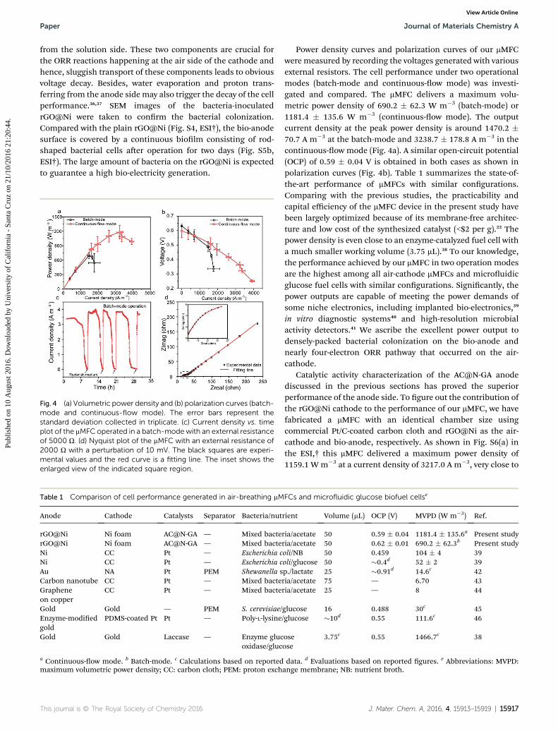
Fig. 4 (a) Volumetric power density and (b) polarization curves (batch-mode and continuous-flow mode). The error bars represent thestandard deviation collected in triplicate. (c) Current density vs. timeplot of the mMFC operated in a batch-mode with an external resistanceof 5000 U. (d) Nyquist plot of the mMFC with an external resistance of2000 U with a perturbation of 10 mV. The black squares are experi-mental values and the red curve is a fitting line. The inset shows theenlarged view of the indicated square region.
Table 1 Comparison of cell performance generated in air-breathing mM
Anode Cathode Catalysts Separator Bacteria/nut
rGO@Ni Ni foam AC@N-GA — Mixed bacterGO@Ni Ni foam AC@N-GA — Mixed bacteNi CC Pt — Escherichia cNi CC Pt — Escherichia cAu NA Pt PEM Shewanella sCarbon nanotube CC Pt — Mixed bacteGrapheneon copper
CC Pt — Mixed bacte
Gold Gold — PEM S. cerevisiae/Enzyme-modiedgold
PDMS-coated Pt Pt — Poly-L-lysine
Gold Gold Laccase — Enzyme glucoxidase/gluc
a Continuous-ow mode. b Batch-mode. c Calculations based on reportedmaximum volumetric power density; CC: carbon cloth; PEM: proton exch
This journal is © The Royal Society of Chemistry 2016
Power density curves and polarization curves of our mMFCwere measured by recording the voltages generated with variousexternal resistors. The cell performance under two operationalmodes (batch-mode and continuous-ow mode) was investi-gated and compared. The mMFC delivers a maximum volu-metric power density of 690.2 � 62.3 W m�3 (batch-mode) or1181.4 � 135.6 W m�3 (continuous-ow mode). The outputcurrent density at the peak power density is around 1470.2 �70.7 A m�3 at the batch-mode and 3238.7 � 178.8 A m�3 in thecontinuous-ow mode (Fig. 4a). A similar open-circuit potential(OCP) of 0.59 � 0.04 V is obtained in both cases as shown inpolarization curves (Fig. 4b). Table 1 summarizes the state-of-the-art performance of mMFCs with similar congurations.Comparing with the previous studies, the practicability andcapital efficiency of the mMFC device in the present study havebeen largely optimized because of its membrane-free architec-ture and low cost of the synthesized catalyst (<$2 per g).22 Thepower density is even close to an enzyme-catalyzed fuel cell witha much smaller working volume (3.75 mL).38 To our knowledge,the performance achieved by our mMFC in two operation modesare the highest among all air-cathode mMFCs and microuidicglucose fuel cells with similar congurations. Signicantly, thepower outputs are capable of meeting the power demands ofsome niche electronics, including implanted bio-electronics,39
in vitro diagnostic systems40 and high-resolution microbialactivity detectors.41 We ascribe the excellent power output todensely-packed bacterial colonization on the bio-anode andnearly four-electron ORR pathway that occurred on the air-cathode.
Catalytic activity characterization of the AC@N-GA anodediscussed in the previous sections has proved the superiorperformance of the anode side. To gure out the contribution ofthe rGO@Ni cathode to the performance of our mMFC, we havefabricated a mMFC with an identical chamber size usingcommercial Pt/C-coated carbon cloth and rGO@Ni as the air-cathode and bio-anode, respectively. As shown in Fig. S6(a) inthe ESI,† this mMFC delivered a maximum power density of1159.1 W m�3 at a current density of 3217.0 A m�3, very close to
FCs and microfluidic glucose biofuel cellse
rient Volume (mL) OCP (V) MVPD (W m�3) Ref.
ria/acetate 50 0.59 � 0.04 1181.4 � 135.6a Present studyria/acetate 50 0.62 � 0.01 690.2 � 62.3b Present studyoli/NB 50 0.459 104 � 4 39oli/glucose 50 �0.4d 52 � 2 39p./lactate 25 �0.91d 14.6c 42ria/acetate 75 — 6.70 43ria/acetate 25 — 8 44
glucose 16 0.488 30c 45/glucose �10d 0.55 111.6c 46
oseose
3.75c 0.55 1466.7c 38
data. d Evaluations based on reported gures. e Abbreviations: MVPD:ange membrane; NB: nutrient broth.
J. Mater. Chem. A, 2016, 4, 15913–15919 | 15917
Journal of Materials Chemistry A Paper
Publ
ishe
d on
10
Aug
ust 2
016.
Dow
nloa
ded
by U
nive
rsity
of
Cal
ifor
nia
- Sa
nta
Cru
z on
21/
10/2
016
21:2
0:44
. View Article Online
our best values (1181.4 � 135.6 W m�[email protected] � 100 A m�3).Furthermore, the RRDE test for the Pt/C catalyst (mass loading:80 mg mg�2) exhibited that the limiting current and onsetpotential were similar to those of AC@N-GA (Fig. S6(b), ESI†)and is substantially better than that of other mMFCs with thePt/C cathode.39,42–46 These results have unequivocally proved thesuperior performance of the rGO@Ni anode. Combining withother characterization techniques showing that the AC@N-GAis an excellent ORR catalyst, we are condent that the excep-tional performance of our mMFC should be due to both thecathode and anode. In addition, the mMFC also displayed stableperformance. Fig. 4c shows the current response of the mMFCdevice during four feeding cycles operated in a batch-mode.Pronounced current generation is observed at the beginning ofevery feeding cycle and it is stable for more than 2 hours.Replenishing the electrolyte results in the complete recovery ofbio-electricity, further suggesting that the performance is quitestable.
Electrochemical impedance spectroscopy (EIS) was carriedout to further characterize the internal resistance of the mMFC.A semicircle (middle-frequency domain) followed by a straightline (mass transfer-control region) is observed in the Nyquistplot as shown in Fig. 4d. By tting the Nyquist plot with anequivalent electric circuit (Fig. S7, ESI†), the values of ohmicresistance (RU), charge transfer resistance (RCT) and diffusionresistance (RD) were obtained and summarized in Table S1,ESI.† As shown in the table, RU (14.6 U) has a small contributionto the total internal resistance (�700 U). Correspondingly, RCT(458.5 U) and RD (227.5 U) dominate the total internal resis-tance. This result could be due to the relatively limited oxygentransport at the cathode. The bacterial adhesion or otherorganic matter attachment at the cathode (Fig. S3, ESI†) mayclog the pores and lower the oxygen transfer efficiency.35
Nevertheless, the total internal resistance of �700 U issubstantially lower than the values of previous reports based onsimilar dimensions.5,6,21,39 The low internal resistance is aninsurance to achieve the superior mMFC performance anddemonstrates the feasibility of the mMFC design.
In order to evaluate the long term stability of the AC@N-GA,we have incorporated it into a mMFC and operated for 20 days.We then disassembled the device, cleaned the AC@N-GA andperformed both XPS (Fig. S8, ESI†) and the RRDE test (Fig. S9,ESI†) to probe the change of N content and catalytic activity,respectively. As shown in Table S2 (in the ESI†), the N content ofthe AC@N-GA aer the test is 5.49 at%, which is slightly higherthan that of the as-prepared AC@N-GA (5.22 at%). Such a smalldiscrepancy is believed to stem from the biomass (bacteria ortheir metabolic products) attached on the catalyst surface.Moreover, the same types of N-functional groups includingpyridinic-N, quaternary-N and pyrrolic-N are observed beforeand aer the stability test. The XPS results conrm the stablecomposition of the AC@N-GA cathode.
RRDE tests with various rotation speeds have been per-formed to conrm the catalytic performance stability, and theresults are depicted in Fig. S9(a), ESI.† The limiting currents atvarious rotating speeds are nearly identical to those of the as-prepared catalyst. An onset potential of +0.82 V vs. RHE is
15918 | J. Mater. Chem. A, 2016, 4, 15913–15919
identied from the RRDE spectrum at 1600 rpm. This onsetpotential is slightly decreased compared to that of the as-prepared catalyst (+0.92 V vs. RHE). (Fig. S9(b), ESI†) Thedecayed onset potential may be due to the biomass coating asillustrated by the XPS test and SEM images (Fig. S5(b), ESI†).This bio-coating hinders reactant transport and impacts thecatalytic performance of ORR catalysts.
Conclusions
In summary, we have successfully fabricated the AC@N-GAcomposite material as an inexpensive and superior ORR cata-lyst. Owing to the ultrahigh surface area and the existence ofN-functional groups, the AC@N-GA displays a very high numberof transferred electrons (3.9) and an ultra-small percentage ofgenerated H2O2 (4.5%). A low-cost, membrane-free mMFC devicewith the AC@N-GA as the air-cathode and rGO@Ni as the bio-anode exhibits superior power densities of 1181.4 � 135.6 Wm�3 (continuous-ow mode) and 690.2 � 62.3 W m�3 (batch-mode), which are substantially higher than those of othermMFCs with a similar conguration. The excellent ORR catalyticperformance of AC@N-GA and the 3D hierarchically porousstructure of rGO@Ni that enables high bacterial communityuptake are believed to be the two crucial factors determining theremarkable performance. We believe the successful fabricationof the AC@N-GA could signicantly advance the mMFC tech-nology towards large-scale manufacturing of commercial elec-tronic products including portable power generators andsensors.
Acknowledgements
This work is also supported by the National Natural ScienceFunds for Distinguished Young Scholar (No. 51325602),National Natural Science Foundation of China (No. 51376203,No. 51276208), Fundamental Research Funds for the CentralUniversities (No. CDJZR14145502) and Overseas, and the HongKong & Macao Scholars Collaborated Research Fund (No.51428601). Y. L. thanks the nancial support from NSF (IIP-1550327). Y. Y. thanks the China Scholarship Council fornancial support. T. L. thanks the nancial support from theChancellor's Dissertation Year Fellowship awarded by UC SantaCruz. We also acknowledge the kind help offered by Wei Yang,Rui Wu and Zeyu Fan.
Notes and references
1 B. E. Logan, B. Hamelers, R. Rozendal, U. Schroder, J. Keller,S. Freguia, P. Aelterman, W. Verstraete and K. Rabaey,Environ. Sci. Technol., 2006, 40, 5181–5192.
2 D. R. Bond, D. E. Holmes, L. M. Tender and D. R. Lovley,Science, 2002, 295, 483–485.
3 E. Kjeang, N. Djilali and D. Sinton, J. Power Sources, 2009,186, 353–369.
4 J. W. Lee and E. Kjeang, J. Power Sources, 2013, 242, 472–477.5 Y. Yang, D. Ye, J. Li, X. Zhu, Q. Liao and B. Zhang, Int. J.Hydrogen Energy, 2015, 40, 11983–11988.
This journal is © The Royal Society of Chemistry 2016
Paper Journal of Materials Chemistry A
Publ
ishe
d on
10
Aug
ust 2
016.
Dow
nloa
ded
by U
nive
rsity
of
Cal
ifor
nia
- Sa
nta
Cru
z on
21/
10/2
016
21:2
0:44
. View Article Online
6 Y. Yang, D. Ye, Q. Liao, P. Zhang, X. Zhu, J. Li and Q. Fu,Biosens. Bioelectron., 2016, 79, 406–410.
7 D. Davila, J. P. Esquivel, N. Sabate and J. Mas, Biosens.Bioelectron., 2011, 26, 2426–2430.
8 J. Kim, J. Hwan Ko, J. Lee, M. Jun Kim and D. Byun, Appl.Phys. Lett., 2014, 104, 223702.
9 J. E. Mink, J. P. Rojas, B. E. Logan and M. M. Hussain, NanoLett., 2012, 12, 791–795.
10 J. E. Mink andM. M. Hussain, ACS Nano, 2013, 7, 6921–6927.11 H. Ren, H. Tian, C. L. Gardner, T.-L. Ren and J. Chae,
Nanoscale, 2016, 8, 3539–3547.12 H. Yuan and Z. He, Nanoscale, 2015, 7, 7022–7029.13 Z. He, J. Liu, Y. Qiao, C. M. Li and T. T. Tan, Nano Lett., 2012,
12, 4738–4741.14 H. Dong, H. Yu, H. Yu, N. Gao and X. Wang, J. Power Sources,
2013, 232, 132–138.15 Z.-S. Wu, S. Yang, Y. Sun, K. Parvez, X. Feng and K. Mullen, J.
Am. Chem. Soc., 2012, 134, 9082–9085.16 H. Yin, C. Zhang, F. Liu and Y. Hou, Adv. Funct. Mater., 2014,
24, 2930–2937.17 C. Huang, C. Li and G. Shi, Energy Environ. Sci., 2012, 5, 8848.18 W. S. Hummers Jr and R. E. Offeman, J. Am. Chem. Soc., 1958,
80, 1339.19 H. Wang, G. Wang, Y. Ling, F. Qian, Y. Song, X. Lu, S. Chen,
Y. Tong and Y. Li, Nanoscale, 2013, 5, 10283–10290.20 J. Xuan, D. Leung, H. Wang, M. K. Leung, B. Wang andM. Ni,
Appl. Energy, 2013, 104, 400–407.21 D. Ye, Y. Yang, J. Li, X. Zhu, Q. Liao, B. Deng and R. Chen, Int.
J. Hydrogen Energy, 2013, 38, 15710–15715.22 Y. Yang, T. Liu, X. Zhu, F. Zhang, D. Ye, Q. Liao and Y. Li,
Adv. Sci., 2016, 3, 1600097.23 X. Zhang, Z. Sui, B. Xu, S. Yue, Y. Luo, W. Zhan and B. Liu, J.
Mater. Chem., 2011, 21, 6494–6497.24 M. A. Worsley, P. J. Pauzauskie, T. Y. Olson, J. Biener,
J. H. Satcher Jr and T. F. Baumann, J. Am. Chem. Soc.,2010, 132, 14067–14069.
25 Z. Sui, Q. Meng, X. Zhang, R. Ma and B. Cao, J. Mater. Chem.,2012, 22, 8767–8771.
26 P. Chen, J.-J. Yang, S.-S. Li, Z. Wang, T.-Y. Xiao, Y.-H. Qianand S.-H. Yu, Nano Energy, 2013, 2, 249–256.
27 K. Liu, Y. Song and S. Chen, Nanoscale, 2015, 7, 1224–1232.
This journal is © The Royal Society of Chemistry 2016
28 Y. Liang, Y. Li, H. Wang, J. Zhou, J. Wang, T. Regier andH. Dai, Nat. Mater., 2011, 10, 780–786.
29 X. Wang, L. Wang, F. Zhao, C. Hu, Y. Zhao, Z. Zhang,S. Chen, G. Shi and L. Qu, Nanoscale, 2015, 7, 3035–3042.
30 M. Park, T. Lee and B.-S. Kim, Nanoscale, 2013, 5, 12255–12260.
31 C. M. Parlett, K. Wilson and A. F. Lee, Chem. Soc. Rev., 2013,42, 3876–3893.
32 D. Guo, R. Shibuya, C. Akiba, S. Saji, T. Kondo andJ. Nakamura, Science, 2016, 351, 361–365.
33 L. Lai, J. R. Potts, D. Zhan, L. Wang, C. K. Poh, C. Tang,H. Gong, Z. Shen, J. Lin and R. S. Ruoff, Energy Environ.Sci., 2012, 5, 7936–7942.
34 S.-S. Li, H.-P. Cong, P. Wang and S.-H. Yu, Nanoscale, 2014, 6,7534–7541.
35 F. Zhang, D. Pant and B. E. Logan, Biosens. Bioelectron., 2011,30, 49–55.
36 S. Yang, B. Jia and H. Liu, Bioresour. Technol., 2009, 100,1197–1202.
37 P. Cristiani, M. Carvalho, E. Guerrini, M. Daghio, C. Santoroand B. Li, Bioelectrochemistry, 2013, 92, 6–13.
38 A. Zebda, L. Renaud, M. Cretin, F. Pichot, C. Innocent,R. Ferrigno and S. Tingry, Electrochem. Commun., 2009, 11,592–595.
39 M. M. Mardanpour and S. Yaghmaei, Biosens. Bioelectron.,2016, 79, 327–333.
40 A. Fraiwan, S. Mukherjee, S. Sundermier, H. S. Lee andS. Choi, Biosens. Bioelectron., 2013, 49, 410–414.
41 H. Hou, L. Li, Y. Cho, P. de Figueiredo and A. Han, PLoS One,2009, 4, e6570.
42 Y. P. Chen, Y. Zhao, K. Q. Qiu, J. Chu, R. Lu, M. Sun,X. W. Liu, G. P. Sheng, H. Q. Yu, J. Chen, W. J. Li, G. Liu,Y. C. Tian and Y. Xiong, Biosens. Bioelectron., 2011, 26,2841–2846.
43 J. E. Mink andM. M. Hussain, ACS Nano, 2013, 7, 6921–6927.44 J. E. Mink, R. M. Qaisi, B. E. Logan and M. M. Hussain, NPG
Asia Mater., 2014, 6, e89.45 C. P. B. Siu and C. Mu, J. Microelectromech. Syst., 2008, 17,
1329–1341.46 M. Togo, A. Takamura, T. Asai, H. Kaji and M. Nishizawa,
Electrochim. Acta, 2007, 52, 4669–4674.
J. Mater. Chem. A, 2016, 4, 15913–15919 | 15919