Embed Size (px)
Citation preview

AS 4508—1999 (Incorporating Amendment No. 1)
Australian Standard™
Thermal resistance of insulation for ductwork used in building airconditioning
AS 4508
Acce
ssed
by
RM
IT U
NIV
ERSI
TY L
IBR
ARY
on 2
9 M
ar 2
006
This Australian Standard was prepared by Committee ME/77, Thermal Insulation Mechanical Services. It was approved on behalf of the Council of Standards Australia on 27 November 1998 and published on 5 February 1999.
The following interests are represented on Committee ME/77:
Air Conditioning and Mechanical Contractors Association of Australia
Association of Consulting Engineers, Australia
Australian Chamber of Commerce and Industry
Australian Industry Group
Australian Institute of Refrigeration, Air Conditioning and Heating
Fibre Glass and Rockwool Insulation Manufacturers Association, Australia
Institution of Engineers Australia
Master Plumbers and Mechanical Services Association of Australia
Thermal Insulation Contractors Association of Australia
Keeping Standards up-to-date Standards are living documents which reflect progress in science, technology and systems. To maintain their currency, all Standards are periodically reviewed, and new editions are published. Between editions, amendments may be issued. Standards may also be withdrawn. It is important that readers assure themselves they are using a current Standard, which should include any amendments which may have been published since the Standard was purchased. Detailed information about Standards can be found by visiting the Standards Australia web site at www.standards.com.au and looking up the relevant Standard in the on-line catalogue. Alternatively, the printed Catalogue provides information current at 1 January each year, and the monthly magazine, The Australian Standard, has a full listing of revisions and amendments published each month. We also welcome suggestions for improvement in our Standards, and especially encourage readers to notify us immediately of any apparent inaccuracies or ambiguities. Contact us via email at [email protected], or write to the Chief Executive, Standards Australia International Ltd, GPO Box 5420, Sydney, NSW 2001.
This Standard was issued in draft form for comment as DR 95192.
Acce
ssed
by
RM
IT U
NIV
ERSI
TY L
IBR
ARY
on 2
9 M
ar 2
006

AS 4508—1999 (Incorporating Amendment No. 1)
Australian Standard™
Thermal resistance of insulation for ductwork used in building airconditioning
First published as AS 4508—1999. Reissued incorporating Amendment No. 1 (November 2000).
COPYRIGHT © Standards Australia International All rights are reserved. No part of this work may be reproduced or copied in any form or by any means, electronic or mechanical, including photocopying, without the written permission of the publisher. Published by Standards Australia International Ltd GPO Box 5420, Sydney, NSW 2001, Australia ISBN 0 7337 2540 7
Acce
ssed
by
RM
IT U
NIV
ERSI
TY L
IBR
ARY
on 2
9 M
ar 2
006

AS 4508—1999
2
PREFACE This Standard was prepared by the Standards Australia Committee ME/77, Thermal Insulation Mechanical Services.
This Standard incorporates Amendment No. 1 (November 2000). The changes required by the Amendment are indicated in the text by a marginal bar and amendment number against the clause, note, table, figure, or part thereof affected.
The objective of this Standard is to provide designers and specifiers of airconditioning systems with common requirements for the optimum thermal performance of ductwork insulation.
This Standard is one of a series of Standards with the objective of improving the thermal performance of pipework, ductwork and equipment. This Standard is particularly directed towards the ductwork used in domestic and commercial heating, ventilating and airconditioning systems operating in the temperature range of 0°C to 50°C. It demonstrates and supports the role of thermal insulation in achieving the system design objectives of providing thermal comfort while at the same time being cost-effective.
Because of the technical difficulty involved in determining the boundary conditions necessary to allow calculation of heat flows and cost-benefit analysis and having due regard to local conditions, such as climate and energy cost, this Standard is derived from extensive computer modelling and, therefore, is largely prescriptive in nature. Nevertheless, the methodology is carefully documented and is provided for application by energy professionals.
This Standard is directed towards the building industry and is of particular relevance to the domestic housing sector. It is unlikely that rigorous thermal design calculations would be carried out for the majority of heating and cooling installations sold for dwellings. Therefore, an approach was sought which would minimize design effort, maximize energy conservation and maximize long-term economic benefits to the community. In developing recommendations, the Committee took into account improved practice in respect of energy use, thermal comfort and cost.
Having regard to the adverse impact which excessive capital costs can give rise to, particularly in the case of non-occupant building owners (and to a lesser extent first home buyers), in as far as these are less likely to require ducted heating and airconditioning, the cost factors, which were adopted in the derivation of the levels of thermal insulation set out in Section 2, were conservatively chosen so as to maximize returns.
The quantification of heating and cooling requirements for the applications of duct insulation was carried out by computer simulation techniques using the program ESP-II as supplied and supported by the Australian Computer Aided Design Services. This program was converted for Australian application by the Australian Institute of Refrigeration, Air- Conditioning and Heating (AIRAH) and the former Commonwealth Department of Housing and Construction and is recognized by all Australian construction and building authorities as a legitimate means of conducting such calculations.
Each building model developed for this analysis was evaluated under various climatic conditions by the use of climatic data developed for use with ESP-II. For this purpose, weather files belonging to the following cities were selected:
(a) Adelaide
(b) Alice Springs
(c) Brisbane
(d) Canberra
Acce
ssed
by
RM
IT U
NIV
ERSI
TY L
IBR
ARY
on 2
9 M
ar 2
006

AS 4508—1999
3
(e) Hobart
(f) Melbourne
(g) Perth
(h) Sydney.
The optimization methodology employed ensures that the present worth of estimated incremental energy savings always exceeds the estimated cost of supplying and installing additional thermal insulation.
The required capacity of heating or cooling plant may be smaller for an airconditioning system which is well insulated, compared with one that has uninsulated ductwork. The optimization procedure used in this Standard considers only energy savings and ignores equipment sizing and capital cost reductions. Thus, the economic benefits that are discussed in this document may well be conservative. For the evaporative cooling analysis equipment sizing and capital cost reductions are included with the energy saving criteria in the optimization procedure.
This Standard represents one of many measures by which buildings may be improved in terms of thermal performance and, therefore, it should be seen as a ‘deemed to comply’ option under any future performance-based Standard. Committee ME/77 is convinced that use of the recommended levels of thermal insulation in heating and cooling ductwork is cost-effective and will contribute to the long-term societal goal of energy conservation.
This Standard is a useful companion to AS 2627.1, Thermal insulation of dwellings, Part 1: Thermal insulation of roof/ceilings and walls in dwellings. AS 2627.1 recommends levels of insulation appropriate for ceilings and the two principal types of walls used in Australian dwellings for almost every conceivable climatic condition encountered in this enormously diverse continent. However, the recommended levels of insulation in this Standard are a far simpler set of only four levels that vary only with the duty cycle and operating environment of the ductwork or fittings.
The term ‘informative’ has been used in this Standard to define the application of the appendix to which it applies. An ‘informative’ appendix is only for information and guidance.
Acce
ssed
by
RM
IT U
NIV
ERSI
TY L
IBR
ARY
on 2
9 M
ar 2
006

AS 4508—1999
4
CONTENTS
Page
SECTION 1 SCOPE AND GENERAL 1.1 SCOPE......................................................................................................................... 5 1.2 APPLICATION ........................................................................................................... 5 1.3 REFERENCED DOCUMENTS................................................................................... 5 1.4 DEFINITIONS............................................................................................................. 5 1.5 THERMAL PERFORMANCE .................................................................................... 6 1.6 THERMAL RESISTANCE.......................................................................................... 6 1.7 CLASSIFICATION ..................................................................................................... 6 1.8 EVALUATION............................................................................................................ 6
SECTION 2 REQUIREMENTS FOR BULK INSULATION THERMAL RESISTANCE 2.1 SCOPE OF SECTION ................................................................................................. 7 2.2 INSULATION THERMAL RESISTANCE ................................................................. 7 2.3 TEST METHODS........................................................................................................ 7 2.4 CIRCULAR INSULATION......................................................................................... 7
SECTION 3 EQUATIONS 3.1 SCOPE OF SECTION ................................................................................................. 8 3.2 THERMAL PERFORMANCE .................................................................................... 8
APPENDICES A THERMAL ANALYSIS OF DUCT INSULATION.................................................. 10 B ECONOMIC EVALUATION AND RESULTS......................................................... 15 C COMPARISON OF ROUND AND PLANAR INSULATION .................................. 17
Acce
ssed
by
RM
IT U
NIV
ERSI
TY L
IBR
ARY
on 2
9 M
ar 2
006

AS 4508—1999
© Standards Australia www.standards.com.au
5
STANDARDS AUSTRALIA
Australian Standard Thermal resistance of insulation for ductwork used in building
airconditioning
S E C T I O N 1 S C O P E A N D G E N E R A L
1.1 SCOPE This Standard sets out requirements relating to the optimum thermal resistance of insulation for rigid and flexible ductwork and fittings used in heating, ventilating and airconditioning (HVAC) systems of buildings and dwellings.
1.2 APPLICATION This Standard is intended for use either by—
(a) regulatory authorities as deemed to comply with requirements they may have for thermal performance of building HVAC systems; or
(b) private individuals, organizations and the like wishing to optimize the thermal performance of HVAC ductwork.
1.3 REFERENCED DOCUMENTS The following documents are referred to in this Standard: AS 1668 The use of mechanical ventilation and airconditioning in buildings 1668.2 Part 2: Mechanical ventilation for acceptable indoor-air quantity
2352 Glossary of terms for thermal insulation of buildings
2464 Methods of testing thermal insulation 2464.5 Part 5: Steady-state thermal transmission properties by means of the heat flow
meter 2464.6 Part 6: Steady-state thermal transmission properties by means of the guarded
hot plate 2464.7 Part 7: Determination of the average thermal resistance of low-density mineral
wool thermal insulation—Batt and blanket type
3595 Energy management programs—Guidelines for financial evaluation of a project
ANSI/ASTM C177 Test method for steady-state heat flux measurements and thermal transmission
properties by means of the guarded-hot-plate apparatus
C518 Test method for steady-state heat flux measurements and thermal transmission properties by means of the heat flow meter apparatus
C1033 Standard test method for steady-state heat transfer properties of pipe insulation installed vertically.
1.4 DEFINITIONS For the purpose of this Standard, the definitions given in AS 2352 apply. Ac
cess
ed b
y R
MIT
UN
IVER
SITY
LIB
RAR
Y on
29
Mar
200
6

AS 4508—1999
www.standards.com.au © Standards Australia
6
1.5 THERMAL PERFORMANCE Ductwork for building HVAC systems shall be designed to minimize the energy requirements for heating and cooling, having due regard for overall costs.
The addition of the thermal resistance specified in this Standard is deemed to comply with this requirement for ducts in the specified areas of the building.
1.6 THERMAL RESISTANCE The required amount of thermal resistance shall be obtained—
(a) by applying the appropriate additional thermal resistance of bulk insulation as specified in Table 2.1; or
(b) by calculating the additional thermal resistance required, in accordance with Section 3, provided that such a calculation yields a total thermal resistance of the duct assembly which is not less than that resulting from the use of bulk insulation RI values from Table 2.1 and the appropriate film coefficients; or
(c) by testing the duct assembly to a whole duct test method such as ASTM C1033 to determine that the thermal resistance of the duct assembly is not less than that resulting from the use of bulk insulation RI values from Table 2.1 and the appropriate film coefficients.
NOTES: 1 Boundary conditions and film coefficients assumed in the analysis are given in Appendix A. 2 Details of the thermal and financial evaluation calculations and the criteria used are given in
Appendices A and B.
1.7 CLASSIFICATION For the purposes of this Standard, HVAC ductwork and associated fittings have been broken down into three separate cases depending on the location and use. The three cases are as follows:
(a) Case 1 Both heating and refrigerative cooling using a combined duct mounted in an unconditioned space for residential or commercial applications.
(b) Case 2 Heating or refrigerative cooling using a duct mounted in an unconditioned space for residential applications, and heating or refrigerative cooling using a duct mounted in a conditioned space for commercial applications.
(c) Case 3 Evaporative cooling using a duct mounted in an unconditioned space for residential or commercial applications.
1.8 EVALUATION 1.8.1 Thermal analysis
NOTE: Guidance on the methodology used and assumptions made in the quantifications of heating and refrigerative cooling requirements for the two cases is given in Appendix A.
1.8.2 Economic evaluation NOTE: Guidance on the methodology used and assumptions made in the financial evaluation of alternative RI values for the duct insulation is given in Appendix B.
Acce
ssed
by
RM
IT U
NIV
ERSI
TY L
IBR
ARY
on 2
9 M
ar 2
006

AS 4508—1999
© Standards Australia www.standards.com.au
7
S E C T I O N 2 R E Q U I R E M E N T S F O R B U L K I N S U L A T I O N T H E R M A L R E S I S T A N C E
2.1 SCOPE OF SECTION This Section sets out the minimum thermal resistance (RI) of bulk insulation to be added to HVAC ducts including connectors and fittings.
2.2 INSULATION THERMAL RESISTANCE Bulk insulation having a minimum thermal resistance value, as given in Table 2.1, shall be applied to all HVAC ductwork and fittings.
TABLE 2.1 MINIMUM BULK INSULATION THERMAL RESISTANCE
(RI) VALUES
RI, m2 K/W System application
1.5 Ductwork—combined heating and refrigerative cooling
0.9 Ductwork—heating or refrigerative cooling
0.6 Ductwork—evaporative cooling
0.6 Fittings—combined heating and refrigerative cooling
0.4 Fittings—heating or cooling, refrigerative or evaporative
NOTE: Thermal resistance values given in Table 2.1 apply to the bulk insulation component of the duct only. The thermal resistance contributions of the duct walls and associated air films assumed in the analysis are provided in Appendix A.
2.3 TEST METHODS To comply with the requirements of Table 2.1, the thermal resistance of bulk insulation shall be measured in a planar configuration in accordance with AS 2464.5, AS 2464.6, AS 2464.7, ASTM C177 or ASTM C518. Thermal resistance tests shall be carried out at 23 ±3°C. Planar thermal resistance tests shall be carried out at ±10% of the thickness at which circular or complex non-rectilinear bulk insulation will be installed (see Clause 2.4).
NOTE: This convention has been adopted because, in general, insulation for ductwork is sold in blanket form and its thermal resistance is predetermined by the insulation manufacturer. The ductwork fabricator or manufacturer need only refer to the labelling on the blanket insulation and the appropriate test results to determine compliance with the provisions of this Section.
2.4 CIRCULAR INSULATION For the purpose of this Standard, the thermal resistance (R) of circular or complex non-rectilinear cross-section bulk insulation may be taken as equivalent to its planar R value only when the final installed bulk insulation thickness has not changed by more than ±10% of the original tested planar bulk insulation thickness.
NOTE: The analysis of round and planar bulk insulation thermal resistance to support this assumption is detailed in Appendix C.
A1
Acce
ssed
by
RM
IT U
NIV
ERSI
TY L
IBR
ARY
on 2
9 M
ar 2
006

AS 4508—1999
www.standards.com.au © Standards Australia
8
S E C T I O N 3 E Q U A T I O N S
3.1 SCOPE OF SECTION This Section gives the equations used in the calculations and evaluations outlined in this Standard.
3.2 THERMAL PERFORMANCE 3.2.1 Insulation thermal resistance (RI) Bulk insulation thermal resistance shall be determined from the following equation:
klR
I
I1 = . . . 1
where
RI = bulk insulation thermal resistance, in m2K/W
lI = bulk insulation thickness, in metres
kI = thermal conductivity of bulk insulation, in W/m.K
3.2.2 Effective composite duct thermal resistance (REFF) Effective composite duct thermal resistance shall be determined from the following equation (see Figure 3.1):
REFF = RINT + RI + REXT . . . 2
where
RINT = thermal resistance of internal duct wall (core) and associated air film in m2 K/W
RI = thermal resistance of bulk insulation in m2K/W
REXT = thermal resistance of external duct wall (sleeve) and associated air film in m2K/W
NOTE: Information on boundary conditions for RINT and REXT is provided in Appendix A.
3.2.3 Radial heat transfer systems For the cylinder shown in Figure 3.2 (of inside radius ri, outside radius ro and 1 m length) exposed to a temperature differential Ti − To the heat flow (q) is given by the following equation:
( )( )irrlog
TTkq
/2
oe
oi −=π . . . 3
with the boundary conditions:
T = Ti at r = ri
T = To at r = ro
L = 1
The thermal resistance is given by the following equation:
krrlog=R
π2)/( ioe . . . 4
A1
Acce
ssed
by
RM
IT U
NIV
ERSI
TY L
IBR
ARY
on 2
9 M
ar 2
006

AS 4508—1999
© Standards Australia www.standards.com.au
9
FIGURE 3.1 EFFECTIVE COMPOSITE DUCT THERMAL RESISTANCE
FIGURE 3.2 CYLINDER
Acce
ssed
by
RM
IT U
NIV
ERSI
TY L
IBR
ARY
on 2
9 M
ar 2
006
AS 4508—1999
www.standards.com.au © Standards Australia
10
APPENDIX A
THERMAL ANALYSIS OF DUCT INSULATION
(Informative)
A1 SCOPE This Appendix outlines the methodology used and assumptions made in the thermal analysis of duct insulation.
The analysis is conducted for typical applications related to each type of system and is repeated for a number of climatic areas to identify related swings and sensitivities.
NOTE: Information on the methodology and assumptions used for the financial evaluation of the results of this analysis are given in Appendix B.
A2 ANALYSIS OF BUILDINGS—CASES 1 AND 2 A2.1 Building assumptions A2.1.1 Residential buildings
The building used in the model consists of a brick veneer single storey cottage with insulated ceiling space and no insulation in the walls. Typical internal heat sources are included to simulate occupation of the spaces, and operation of lighting and equipment.
The roof space is simulated as a separate space with a floating temperature governed by the heat losses and gains through the roof, the ceiling and the airconditioning duct.
The underfloor space is simulated as a separate space with a floating temperature governed by the heat losses and gains through infiltration from the floor above and the airconditioning duct.
A2.1.2 Commercial buildings
The commercial building application involves ductwork located in the return air space (conditioned) or plant room (unconditioned) of a typical multistorey fully airconditioned building. The model used for the analysis consists of a 14-storey building with a square floor plan with 50% glazed area consisting of double glazed windows with a shading coefficient of 0.57 and with 100 mm concrete and plaster curtain wall. The top floor was assumed to form the plant room, insulating the top occupied floor from the roof.
The airconditioning system is divided into four perimeter zones and one centre zone on each floor, and a separate heating/cooling calculation is conducted for each.
A2.2 System operation assumptions A2.2.1 Case 1
The systems for Case 1 cover residential buildings operating under the assumptions given in Table A1 or commercial buildings operating under the assumptions given in Table A2.
A2.2.2 Case 2
The systems for Case 2 cover residential buildings operating under the assumptions given in Table A3 or commercial buildings operating under the assumptions given in Table A4.
Acce
ssed
by
RM
IT U
NIV
ERSI
TY L
IBR
ARY
on 2
9 M
ar 2
006
AS 4508—1999
© Standards Australia www.standards.com.au
11
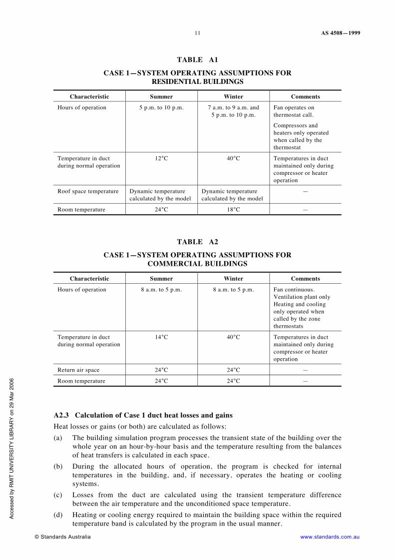
TABLE A1
CASE 1—SYSTEM OPERATING ASSUMPTIONS FOR RESIDENTIAL BUILDINGS
Characteristic Summer Winter Comments
Hours of operation 5 p.m. to 10 p.m. 7 a.m. to 9 a.m. and 5 p.m. to 10 p.m.
Fan operates on thermostat call.
Compressors and heaters only operated when called by the thermostat
Temperature in duct during normal operation
12°C 40°C Temperatures in duct maintained only during compressor or heater operation
Roof space temperature Dynamic temperature calculated by the model
Dynamic temperature calculated by the model
—
Room temperature 24°C 18°C —
TABLE A2
CASE 1—SYSTEM OPERATING ASSUMPTIONS FOR COMMERCIAL BUILDINGS
Characteristic Summer Winter Comments
Hours of operation 8 a.m. to 5 p.m. 8 a.m. to 5 p.m. Fan continuous. Ventilation plant only Heating and cooling only operated when called by the zone thermostats
Temperature in duct during normal operation
14°C 40°C Temperatures in duct maintained only during compressor or heater operation
Return air space 24°C 24°C —
Room temperature 24°C 24°C —
A2.3 Calculation of Case 1 duct heat losses and gains Heat losses or gains (or both) are calculated as follows: (a) The building simulation program processes the transient state of the building over the
whole year on an hour-by-hour basis and the temperature resulting from the balances of heat transfers is calculated in each space.
(b) During the allocated hours of operation, the program is checked for internal temperatures in the building, and, if necessary, operates the heating or cooling systems.
(c) Losses from the duct are calculated using the transient temperature difference between the air temperature and the unconditioned space temperature.
(d) Heating or cooling energy required to maintain the building space within the required temperature band is calculated by the program in the usual manner.
Acce
ssed
by
RM
IT U
NIV
ERSI
TY L
IBR
ARY
on 2
9 M
ar 2
006

AS 4508—1999
www.standards.com.au © Standards Australia
12
Due to the limitations of the program, the summer and winter cases are conducted as separate models and then combined. A further limitation in the program causes losses in the ductwork to be calculated during the preset operating times although, in the case of a domestic situation, the airconditioning or heating system would only be operated when necessary. This tends to overestimate the true losses from the ductwork as the operations move away from peak heating and cooling seasons.
The following calculations and adjustments are made to arrive at a suitable estimate of the annual losses from the ductwork:
(a) Duct losses calculated for the peak heating and cooling months are retained at their full value on the assumption that during this period the systems would be operating during the assumed times.
(e) For the remaining periods, the monthly losses calculated by the program are adjusted on a pro-rata basis in relation to the total heating or cooling needed to maintain the space conditions specified. The following equation is used:
( ) ( )( )RMBO QQQ / Q = (Dm)(De) × . . . A1
where
Q(De) = effective heat loss or gain from the duct
Q(Dm) = calculated duct heat gain/loss for the month
Q(Rm) = calculated room heat gain/loss for the peak month
Q(Bo) = calculated room heat gain/loss for the month under consideration
The effect of the above equation is to adjust losses for operating hours while adjusting for the climatic differences experienced during the entire year.
The annual heat losses or gains from the duct surface are then calculated as the sum of the individual months. All heat losses and gains are calculated on a duct surface unit area basis.
TABLE A3
CASE 2—SYSTEM OPERATING ASSUMPTIONS FOR RESIDENTIAL BUILDINGS
Characteristic Winter Comments
Hours of operation 7 a.m. to 9 a.m. Fan operates on thermostat call
5 p.m. to 10 p.m. Heaters only operated when called by the thermostat
Temperature in duct during normal operation
40°C Temperatures in duct maintained only during heater operation
Underfloor space temperature
Dynamic temperature calculated by the model
—
Room temperature 18°C —
Acce
ssed
by
RM
IT U
NIV
ERSI
TY L
IBR
ARY
on 2
9 M
ar 2
006

AS 4508—1999
© Standards Australia www.standards.com.au
13
TABLE A4
CASE 2—SYSTEM OPERATING ASSUMPTIONS FOR COMMERCIAL BUILDINGS
Characteristic Summer Winter Comments
Hours of operation 8 a.m. to 5 p.m. 8 a.m. to 5 p.m. Fan conditions. Ventilation plant only. Heating and cooling only operated when called by the zone thermostats
Temperature in duct during normal operation
14°C 40°C Temperatures in duct maintained only during compressor of heater operation
Plantroom Dynamic temperature calculated by the model
Dynamic temperature calculated by the model
—
Room temperature 24°C 24°C —
A2.4 Calculation of Case 2 duct heat losses and gains Heat losses or gains from the ductwork are calculated as follows: (a) The building simulation program processes the transient state of the building over the
whole year on an hour-by-hour basis, and calculates the temperature in each zone resulting from the balances of heat transfers.
(f) A call for heating or cooling is registered in each zone as necessary to maintain the desired conditions.
(g) Heating or cooling energy required to maintain each zone within the required temperature band is calculated by the program in the usual manner.
The following calculations and adjustments are made to arrive at a suitable estimate of the annual losses from the ductwork: (i) The annual equivalent full load operating hours of heating and cooling operations
calculated for each zone by dividing the total (heating/cooling) delivered heat quantities by the peak system capacity for delivering heating and cooling.
(ii) The heat losses and heat gains for a typical square metre of duct are calculated for each zone using the following equation:
Q(H) = Ophrs(H) × ΔT(H) × U(H) . . . A2 Q(C) = Ophrs(C) × ΔT(C) × U(C) . . . A3
where Q = effective heat loss or gain from the duct Ophrs = is the total operating hours under heating or cooling ΔT = is the temperature difference between the supply air in the duct and the
return air in ceiling space H and C = refer to operations under (H)eating or (C)ooling U = overall heat transfer coefficient of the duct
(iii) The total heat gains and losses from each zone are combined across the entire building on a pro rata basis, based on the supply air flow calculated for each zone.
NOTE: Airflow calculations are carried out in accordance with AS 1668.2.
Acce
ssed
by
RM
IT U
NIV
ERSI
TY L
IBR
ARY
on 2
9 M
ar 2
006
AS 4508—1999
www.standards.com.au © Standards Australia
14
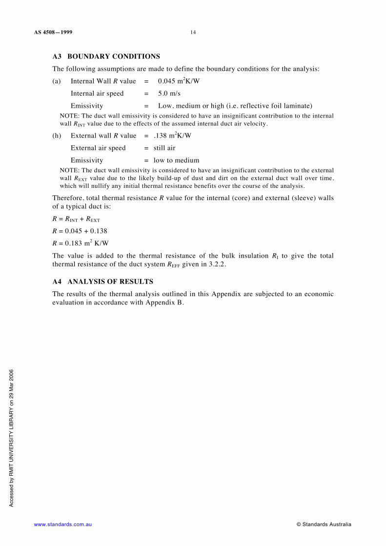
A3 BOUNDARY CONDITIONS The following assumptions are made to define the boundary conditions for the analysis:
(a) Internal Wall R value = 0.045 m2K/W
Internal air speed = 5.0 m/s
Emissivity = Low, medium or high (i.e. reflective foil laminate) NOTE: The duct wall emissivity is considered to have an insignificant contribution to the internal wall RINT value due to the effects of the assumed internal duct air velocity.
(h) External wall R value = .138 m2K/W
External air speed = still air
Emissivity = low to medium NOTE: The duct wall emissivity is considered to have an insignificant contribution to the external wall REXT value due to the likely build-up of dust and dirt on the external duct wall over time, which will nullify any initial thermal resistance benefits over the course of the analysis.
Therefore, total thermal resistance R value for the internal (core) and external (sleeve) walls of a typical duct is:
R = RINT + REXT
R = 0.045 + 0.138
R = 0.183 m2 K/W
The value is added to the thermal resistance of the bulk insulation RI to give the total thermal resistance of the duct system REFF given in 3.2.2.
A4 ANALYSIS OF RESULTS The results of the thermal analysis outlined in this Appendix are subjected to an economic evaluation in accordance with Appendix B.
Acce
ssed
by
RM
IT U
NIV
ERSI
TY L
IBR
ARY
on 2
9 M
ar 2
006
AS 4508—1999
© Standards Australia www.standards.com.au
15
APPENDIX B
ECONOMIC EVALUATION AND RESULTS
(Informative)
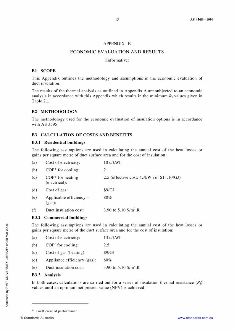
B1 SCOPE This Appendix outlines the methodology and assumptions in the economic evaluation of duct insulation.
The results of the thermal analysis as outlined in Appendix A are subjected to an economic analysis in accordance with this Appendix which results in the minimum RI values given in Table 2.1.
B2 METHODOLOGY The methodology used for the economic evaluation of insulation options is in accordance with AS 3595.
B3 CALCULATION OF COSTS AND BENEFITS B3.1 Residential buildings The following assumptions are used in calculating the annual cost of the heat losses or gains per square metre of duct surface area and for the cost of insulation:
(a) Cost of electricity: 10 c/kWh
(b) COP* for cooling: 2
(c) COP* for heating (electrical):
2.5 (effective cost; 4c/kWh or $11.10/GJ)
(d) Cost of gas: $9/GJ
(e) Applicable efficiency—(gas):
80%
(f) Duct insulation cost: 3.90 to 5.10 $/m2.R
B3.2 Commercial buildings The following assumptions are used in calculating the annual cost of the heat losses or gains per square metre of the duct surface area and for the cost of insulation:
(a) Cost of electricity: 13 c/kWh
(b) COP* for cooling: 2.5
(c) Cost of gas (heating): $9/GJ
(d) Appliance efficiency (gas): 80%
(e) Duct insulation cost: 3.90 to 5.10 $/m2.R
B3.3 Analysis In both cases, calculations are carried out for a series of insulation thermal resistance (RI) values until an optimum net present value (NPV) is achieved.
* Coefficient of performance.
Acce
ssed
by
RM
IT U
NIV
ERSI
TY L
IBR
ARY
on 2
9 M
ar 2
006

AS 4508—1999
www.standards.com.au © Standards Australia
16
The following factors were used in calculating the net present values of the alternative insulation levels used in the study:
(a) Rate of return: 15%
(b) Tax rate: 33%
(c) Inflation factor: 2.5%
(d) Life of plant: 15 years
(e) Resulting discount rate: 10.05%
(f) Resulting F factor: 11.3682
B4 CONCLUSIONS AND RECOMMENDATIONS All of the evaluations carried out establish a strong case for increased insulation levels in ductwork used in domestic and commercial applications. In all cases, the order between the climatic areas changes substantially.
The method of calculation used in the study filters out many variables related to building size by reducing all factors to a square metre basis. The results should, therefore, hold true for variations in building and system sizes. Variations in operation and building types, however, may affect the operating period of the heating and cooling systems, thus affecting the optimum level of insulation.
The outcomes of modelling for the application cases and the full series of cities studied have not been given in this Appendix. Note that only the minimum values from this series are used in the recommended levels given in Table 2.1. Nevertheless, the Committee was mindful of common practice in Australian buildings which usually have less insulation on ductwork than those levels recommended in this Standard and, all too often, none at all.
By outlining the modelling procedure and necessary assumptions, this Appendix provides the engineering professional with a means for modification of the levels of bulk insulation thermal resistance prescribed should significant changes in the factors occur.
Acce
ssed
by
RM
IT U
NIV
ERSI
TY L
IBR
ARY
on 2
9 M
ar 2
006

AS 4508—1999
© Standards Australia www.standards.com.au
17
APPENDIX C
COMPARISON OF ROUND AND PLANAR INSULATION
(Informative)
C1 INTRODUCTION In most cases, the planar performance values for insulation thermal resistance may be used for the referred application. However, for round ductwork, the outer surface area of the insulated ductwork and compressibility effects of the insulation material, as it is wrapped around a circular object, could produce variations over the planar performance of the insulation. Therefore, it is important that the thermal performance of planar insulation be analysed comparatively with the thermal performance of round insulation in order to establish any differences.
After completing the analysis as outlined in this Appendix, it is considered, for the purposes of this Standard, that the thermal performance of insulation in the two configurations are equivalent, i.e. the thermal resistance (R) of circular or complex non-rectilinear cross-sectional insulation may be taken as equivalent to its planar R value provided that the final thickness is within reasonable limits of the test thickness.
C2 METHODOLOGY C2.1 General The thickness of insulation required to produce each of the R values and the temperature conditions specified in Table 2.1, for each case, are calculated for a range of duct diameters between 100 mm to 2000 mm. The same conditions are used to calculate the thickness of insulation required to produce the specified R value for the planar case.
C2.2 Duct diameters The following ductwork diameters, in millimetres, are used in the calculations:
100 150 200 250 300 400 500 600 800 1000 1200 1500 2000
C2.3 Equations and relationships used The basic relationship for thermal conductivity used in the analysis is given by the following Equation:
k = (a + b + c/d)/1000 . . . C1
where
k = thermal conductivity
a = 0.2572 × temp0.81
b = 0.0527 × (1 + 0.13 × temp/100) × density0.91
c = 4 × 0.0000567 × temp3 × Δr
d = 2/0.9 – 1 + 30 × density × Δr
Δr = the difference in inner and outer radius of the duct/insulation assembly
Acce
ssed
by
RM
IT U
NIV
ERSI
TY L
IBR
ARY
on 2
9 M
ar 2
006
AS 4508—1999
www.standards.com.au © Standards Australia
18
For the calculation of density, it is assumed that the material expands as it is wrapped around the duct, producing a density at a given thickness as given in the following equation:
rin change radiusinner 2radiusinner 2 density free =Density
××
×× . . . C2
Based on geometric relationships, the value of resistance for a circular duct system may be expressed as follows:
krrr
π2)/) + (( log = Resistance e Δ
. . . C3
and the value of heat flow as follows:
r)/r) + ((rTk2 = qΔ
Δπ
elog . . . C4
where
ΔT = is the difference in temperature between the inner and outer surfaces of the insulation.
C2.4 Iterative analysis methodology The methodology used in calculating the thickness of insulation required to achieve a defined set of values is as follows:
(a) Thermal resistance, R.
(b) Duct inside air temperature, Tin.
(c) Duct outside temperature, Tout.
The methodology used is iterative involving the following steps:
(i) An initial approximation of heat flow (q) is made based on nominal temperatures and resistances selected.
(ii) The value of R is calculated based on a linear temperature relationship across the insulation, and density variations calculated over annular sections of the insulation of 0.1 mm thickness.
(iii) Based on the calculated R, a new value of q is calculated.
(vi) The new value of q is compared with the original estimate and if the difference is larger than 0.5%, the new value of q is used as the next approximation. The process is then repeated.
Once the value of q has converged to the required accuracy, the values of kI and RI are calculated from the following equations:
) (2) / (log
= inout
inouteI
TTrrq
k−π
. . . C5
klR
I
II = . . . C6
where
RI = insulation thermal resistance, in m2K/W
kI = thermal conductivity of insulation, in W/mK
lI = thickness, in metres NOTE: RINT and REXT coefficients cancel out in the analysis. Ac
cess
ed b
y R
MIT
UN
IVER
SITY
LIB
RAR
Y on
29
Mar
200
6

Standards Australia Standards Australia is an independent company, limited by guarantee, which prepares and publishes most of the voluntary technical and commercial standards used in Australia. These standards are developed through an open process of consultation and consensus, in which all interested parties are invited to participate. Through a Memorandum of Understanding with the Commonwealth government, Standards Australia is recognized as Australia’s peak national standards body.
Australian Standards Australian Standards are prepared by committees of experts from industry, governments, consumers and other relevant sectors. The requirements or recommendations contained in published Standards are a consensus of the views of representative interests and also take account of comments received from other sources. They reflect the latest scientific and industry experience. Australian Standards are kept under continuous review after publication and are updated regularly to take account of changing technology.
International Involvement Standards Australia is responsible for ensuring that the Australian viewpoint is considered in the formulation of international Standards and that the latest international experience is incorporated in national Standards. This role is vital in assisting local industry to compete in international markets. Standards Australia represents Australia at both ISO (The International Organization for Standardization) and the International Electrotechnical Commission (IEC).
Electronic Standards All Australian Standards are available in electronic editions, either downloaded individually from our Web site, or via on-line and CD ROM subscription services. For more information phone 1300 65 46 46 or visit us at
www.standards.com.au
Acce
ssed
by
RM
IT U
NIV
ERSI
TY L
IBR
ARY
on 2
9 M
ar 2
006
GPO Box 5420 Sydney NSW 2001
Administration Phone (02) 8206 6000 Fax (02) 8206 6001 Email [email protected] Customer Service Phone 1300 65 46 46 Fax 1300 65 49 49 Email [email protected] Internet www.standards.com.au
ISBN 7337 2450 7
Printed in Australia
Acce
ssed
by
RM
IT U
NIV
ERSI
TY L
IBR
ARY
on 2
9 M
ar 2
006

This page has been left blank intentionally.
Acce
ssed
by
RM
IT U
NIV
ERSI
TY L
IBR
ARY
on 2
9 M
ar 2
006
![User's Model MY40 Insulation Resistance Tester [ …Insulation Resistance Tester [ Operation Manual ] This manual describes the specifications and handling precautions of the insulation](https://img.pdfslide.us/doc/110x75/5e58e655eb65b66d2954e0fb/users-model-my40-insulation-resistance-tester-insulation-resistance-tester-.jpg)