Embed Size (px)
Citation preview
Arxx High Performance Wallsystem
Prescriptive Design Manual for Residential
Structures
Base on
Building Code Requirements for Structural Concrete (ACI-318)
Prepared for
Arxx Building Products, Inc. 800 Division Street
Cobourg, Ontario, Canada K9A 5V2
800-293-3210
Prepared by
NAHB Research Center, Inc. 400 Prince George’s Boulevard
Upper Marlboro, MD 20774-8731
April 2004
iiiARXX® PRESCRIPTIVE DESIGN REQUIREMENTS
Table of Contents
1.0 General 1
1.1 Approach 2
1.2 Scope 2
1.3 Arxx Wallsystem Limitations 3
1.4 Limitations for Seismic Design Categories C, D1, and D2 4
1.5 Definitions 5
2.0 Materials, Shapes and Standard Sizes 9
2.1 Concrete 10
2.2 Reinforcing Steel 10
2.3 Floor and Roof System Construction 12
3.0 Foundations 15
3.1 Footings 16
3.2 Arxx Foundation Wall Requirements 16
4.0 Arxx Above-Grade Wall Requirements 25
5.0 Arxx Minimum Solid Wall Length and Wall-Opening Requirements 33
5.1 Minimum Length of Arxx Wall Without Openings 34
5.2 Reinforcement Around Openings 43
5.3 Lintels 43
6.0 Arxx Connection Requirements 65
6.1 Arxx Wall-to-Footing Connections 66
6.2 Arxx Wall-to-Floor Connections 67
6.3 Arxx Wall-to-Roof Connections 70
7.0 References 73
Appendix A – Illustrative Examples
Appendix B – Engineering Technical Substantiation
Appendix C – Metric Conversion Factors
PDR Section TOC-intro 7/31/06 11:20 AM Page iii
vARXX® PRESCRIPTIVE DESIGN REQUIREMENTS
Introduction
This document provides prescriptive requirements for the construction of one- and two-family residential dwellings including
townhouses constructed using Arxx Wallsystem. The requirements are consistent with current U.S. building code provisions,
engineering standards, and Arxx Building Products, Inc.’s specifications. While provisions in this document were developed by
applying accepted engineering practices and practical construction techniques, users of the document should verify its
compliance with local building code requirements.
Three appendices are also provided. Appendix A contains examples illustrating the proper application of the prescriptive
requirements for a typical home. Appendix B contains the engineering calculations and assumptions used to generate the
various prescriptive requirements. The requirements are based on U.S. customary units; International System (SI) conversion
factors are provided in Appendix C in accordance with ASTM E 380 [1].
Information is presented in both U.S. customary units and International System (SI) units except for reinforcement bar sizes,
which are only presented in U.S. customary units. Refer to Appendix C for the corresponding reinforcement bar size in SI units.
Note
The user is strongly encouraged to refer to Appendix A before applying the Arxx Prescriptive Design Requirements to a specific
house design.
The user should refer to applicable building code requirements when exceeding the limitations of this document, when
requirements conflict with the building code, or when an engineered design is specified. This document is not intended to
limit the appropriate use of concrete construction not specifically prescribed. This document is also not intended to restrict the
use of sound judgment or engineering analysis of specific applications that may result in designs with improved performance
and economy.
PDR Section TOC-intro 7/31/06 11:20 AM Page v
General
1.0
2
1.0 General
1.1 – Approach
1.1.1 The prescriptive requirements are based primarily on the Prescriptive Method for Insulating Concrete Forms in
Residential Construction [2], Building Code Requirements for Structural Concrete [3], and the Structural Design of Insulating
Concrete Form Walls in Residential Construction [4] for member strength and reinforcement requirements, and is intended to be
consistent with the provisions in the International Residential Code (IRC 2003)[17]. The design loading requirements are based
on Minimum Design Loads for Buildings and Other Structures [5]. The engineering calculations and determinations that form the
basis for this document are discussed in Appendix B, Engineering Technical Substantiation.
1.2 – Scope
1.2.1 These provisions apply to the construction of detached one- and two-family homes, townhouses, and other attached
single-family dwellings in accordance with the general limitations of Table 1.1. The limitations are intended to define the
appropriate use of this document for most one- and two-family dwellings including townhouses. An engineered design shall be
required for houses built along the immediate, hurricane-prone coastline subjected to storm surge (i.e., beach front property).
Intermixing of the present provisions with other construction materials in a single structure shall be in accordance with the
applicable building code requirements for that material, the general limitations set forth in Table 1.1, and relevant provisions of
this document. An engineered design shall be required for applications that do not meet the limitations of Table 1.1.
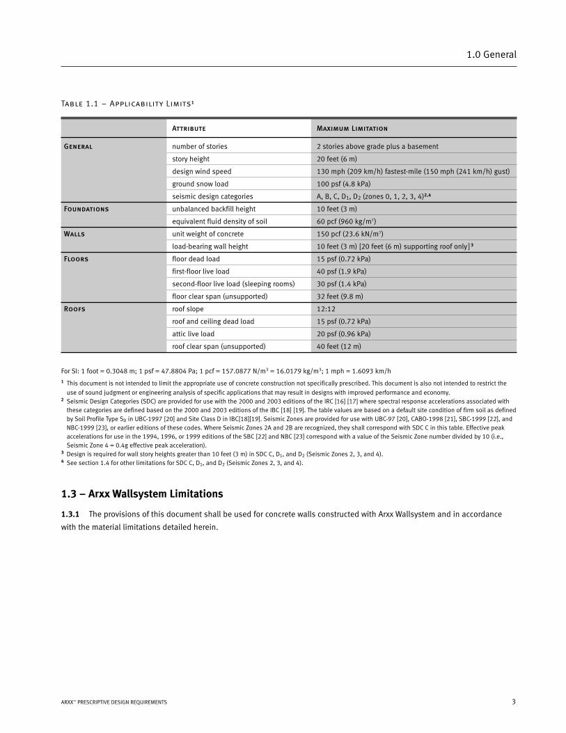
Table 1.1 – Applicability Limits1
Attribute Maximum Limitation
General number of stories 2 stories above grade plus a basement
story height 20 feet (6 m)
design wind speed 130 mph (209 km/h) fastest-mile (150 mph (241 km/h) gust)
ground snow load 100 psf (4.8 kPa)
seismic design categories A, B, C, D1, D2 (zones 0, 1, 2, 3, 4)2,4
Foundations unbalanced backfill height 10 feet (3 m)
equivalent fluid density of soil 60 pcf (960 kg/m3)
Walls unit weight of concrete 150 pcf (23.6 kN/m3)
load-bearing wall height 10 feet (3 m) [20 feet (6 m) supporting roof only ] 3
Floors floor dead load 15 psf (0.72 kPa)
first-floor live load 40 psf (1.9 kPa)
second-floor live load (sleeping rooms) 30 psf (1.4 kPa)
floor clear span (unsupported) 32 feet (9.8 m)
Roofs roof slope 12:12
roof and ceiling dead load 15 psf (0.72 kPa)
attic live load 20 psf (0.96 kPa)
roof clear span (unsupported) 40 feet (12 m)
For SI: 1 foot = 0.3048 m; 1 psf = 47.8804 Pa; 1 pcf = 157.0877 N/m3 = 16.0179 kg/m3; 1 mph = 1.6093 km/h1 This document is not intended to limit the appropriate use of concrete construction not specifically prescribed. This document is also not intended to restrict the
use of sound judgment or engineering analysis of specific applications that may result in designs with improved performance and economy.2 Seismic Design Categories (SDC) are provided for use with the 2000 and 2003 editions of the IRC [16] [17] where spectral response accelerations associated with
these categories are defined based on the 2000 and 2003 editions of the IBC [18] [19]. The table values are based on a default site condition of firm soil as definedby Soil Profile Type SD in UBC-1997 [20] and Site Class D in IBC[18][19]. Seismic Zones are provided for use with UBC-97 [20], CABO-1998 [21], SBC-1999 [22], andNBC-1999 [23], or earlier editions of these codes. Where Seismic Zones 2A and 2B are recognized, they shall correspond with SDC C in this table. Effective peakaccelerations for use in the 1994, 1996, or 1999 editions of the SBC [22] and NBC [23] correspond with a value of the Seismic Zone number divided by 10 (i.e.,Seismic Zone 4 = 0.4g effective peak acceleration).
3 Design is required for wall story heights greater than 10 feet (3 m) in SDC C, D1, and D2 (Seismic Zones 2, 3, and 4).4 See section 1.4 for other limitations for SDC C, D1, and D2 (Seismic Zones 2, 3, and 4).
1.3 – Arxx Wallsystem Limitations
1.3.1 The provisions of this document shall be used for concrete walls constructed with Arxx Wallsystem and in accordance
with the material limitations detailed herein.
3ARXX™ PRESCRIPTIVE DESIGN REQUIREMENTS
1.0 General
4
1.0 General
1.4 – Limitations for Seismic Design Categories C, D1, and D2
In Seismic Design Categories (SDC) C, D1, and D2, these provisions shall only apply to buildings constructed with above grade
Arxx Wallsystem walls meeting the following requirements:
› Rectangular buildings with a maximum building aspect ratio of 2:1. The building aspect ratio shall be determined
by dividing the longest dimension of the building by the shortest dimension of the building. For rectangular buildings
with interior Arxx walls constructed as required for exterior walls and connected to roof and wall systems as required
in Chapter 6, the maximum building aspect ratio shall apply to each part of the building as separated by the
interior wall(s).
› Above grade Arxx walls are aligned vertically with the walls below.
› Cantilever and setback construction shall not be permitted. Cantilevered or setback construction of light-frame
construction supported on Arxx walls shall be permitted in accordance with the local governing building code.
› The weight of interior and exterior finishes applied to Arxx walls shall not exceed 8 psf (0.38 kN/m2) except where
adjustment factors are provided for heavier wall finish weights not exceeding 40 psf (1.9 kN/m2).
› The gable portion of Arxx walls shall be constructed of light-frame construction.
› Roof systems supported on above grade Arxx walls shall include an attic floor system constructed in accordance with
Section 2.3 and attached to the top of the Arxx walls in accordance with Section 6.2.1. to provide lateral support to
the walls against earthquake forces.
5ARXX™ PRESCRIPTIVE DESIGN REQUIREMENTS
1.0 General
1.5 – Definitions
> : Greater than
< : Less than
≥ : Greater than or equal to
≤ : Less than or equal to
;(Semi-colon)
The semi colon (;) shown in the tables
contained in this document indicate, ‘OR’
(i.e. #3@32"; #4@48" indicates that either
a #3 OR #4 reinforcing bar can be used).
4", 6" or 8"
Refers to the nominal dimension of concrete
wall thickness formed by the Arxx forms.
Accepted Engineering Practice
An engineering approach that conforms
to accepted principles, tests, technical
standards, and sound judgment.
Approved
Reference to approval by the building code
authority having jurisdiction. A rational
design by a competent design professional
shall constitute grounds for approval.
Attic
The enclosed space between the ceiling
joists of the top-most floor and the roof
rafters of a building not intended for
occupancy but sometimes used for storage.
Authority Having Jurisdiction
The organization, political subdivision,
office, or individual charged with the
responsibility of administering and enforcing
the provisions of applicable building codes.
Backfill
The soil that is placed adjacent to completed
portions of a below-grade structure (i.e.,
basement) with suitable compaction and
allowance for settlement.
Basement
That portion of a building that is partly or
completely below grade and which may be
used as habitable space.
Building
Any one- or two-family dwelling or portion
thereof that is used for human habitation.
Building Length
The dimension of a building that is perpen-
dicular to roof rafters, roof trusses, or floor
joists. The longer plan dimension, L, of a
building.
Building Width
The dimension of a building that is parallel
to roof rafters, roof trusses, or floor joists.
The shorter plan dimension, W, of a building.
Clear Span
Corresponds to the span of the floor or roof
structure (i.e. joists or trusses) between
load-bearing walls or beams.
Cold Joint
A joint or discontinuity resulting from
concrete cast against concrete that has
already set or cured.
Compressive Strength
The maximum ability of concrete to resist
a compressive load, usually measured in
pounds per square inch (psi) or pascals (Pa).
The compressive strength is based on
compression tests of concrete cylinders that
are moist-cured for 28 days in accordance
with ASTM C 31 [6] and ASTM C 39 [7].
Crawlspace
A type of building foundation that uses a
perimeter foundation wall to create an
under-floor space which is not habitable.
Dead Load
Forces resulting from the weight of walls,
partitions, framing, floors, ceilings, roofs,
and all other permanent construction
entering into, and becoming part of, a
building.
Deflection
Elastic movement of a loaded structural
member or assembly (i.e., beam or wall).
Design Professional
An architect or engineer, registered
or licensed to practice professional
architecture or engineering, as defined by
the statutory requirements of the laws
of the state in which the project is to
be constructed.
Design (or Basic) Wind Speed
Related to winds that are expected to be
exceeded once every 50 years at a given site
(i.e., 50-year return period). Wind speeds in
this document are given in units of miles per
hour (mph) by “gust” measurements. Wind
exposure category B is assumed in this
document in accordance with ASCE 7 [5] to
provide design wind loads. The wind loads
are adequate for buildings situated in
typical suburban, urban, and wooded
terrain. Wind speed-up from topographic
effects (i.e., protruding hills and ridges) is
not considered in this document.
Dwelling
Any building that contains one or two
dwelling units for living purposes.
Eccentric Load
A force imposed on a structural member at
some point other than its centerline, such as
the forces transmitted from the floor joists to
an exterior wall through a ledger board
connection.
Equivalent Fluid Density
The mass of a soil per unit volume treated as
a fluid mass for the purpose of determining
lateral design loads produced by the soil on
an adjacent structure.
Flat Wall
A solid concrete wall of uniform thickness
produced by Arxx Wallsystem.
Floor Joist
A horizontal structural framing member that
supports floor loads.
Footing
A below-grade foundation component that
supports the foundation wall and transmits
loads directly to the underlying earth.
6
1.0 General
Foundation
The structural elements through which the
load of a structure is transmitted to the
earth.
Foundation Wall
The structural element of a foundation that
resists lateral earth pressure and transmits
the load of a structure to the earth; includes
basement, stem, and crawlspace walls.
Grade
The finished ground level adjoining the
building at all exterior walls.
Grade Plane
A reference plane representing the average
of the finished ground level adjoining the
building at all exterior walls.
Ground Snow Load
Design load on the ground due to snow
accumulation developed from a statistical
analysis of weather records usually based
on a 50-year snow accumulation.
Horizontal Reinforcement
Steel reinforcement placed horizontally
in concrete walls to provide resistance
to temperature and shrinkage cracking.
In certain circumstances, horizontal
reinforcement is required for additional
strength around openings and in high
loading conditions such as experienced in
hurricanes and earthquakes.
Insulating Concrete Forms (ICFs)
A concrete forming system using stay-in-
place forms of foam plastic insulation for
constructing cast-in-place concrete walls.
Interpolation
A mathematical process used to compute
an intermediate value between two given
values assuming a linear relationship.
Lap Splice
A splice formed by extending reinforcement
bars past each other a specified distance to
permit the force in one bar to be transferred
by bond stress through the concrete and
into the second bar. Used when the length
of one continuous reinforcement bar is not
practical for placement.
Lateral Load
A horizontal force, created by wind or
earthquake, acting on a structure or its
components.
Lateral Support
A horizontal member providing stability
to a column or wall across its smallest
dimension. Walls designed in accordance
with Section 5.0 provide lateral stability to
the whole building when experiencing wind
or earthquake events.
Light Frame Roof
An assembly having a roof and ceiling
dead load in compliance with Table 1.1
Applicability Limits.
Lintel
A horizontal structural element of reinforced
concrete located above an opening in a wall
to support the construction above.
Live Load
Any gravity load that is not permanently
applied to a structure; typically transient
and sustained gravity forces resulting from
the weight of people and furnishings,
respectively.
Roof Snow Load
Uniform live load on the roof due to snow
accumulation; roughly equivalent to 70 to
80 percent of the ground snow load in
accordance with ASCE 7 [5].
Seismic Load
The force exerted on a building structure
resulting from seismic (earthquake) ground
motions.
Seismic Design Categories or Zones
Designated areas associated with a
particular level or range of seismic risk
and associated seismic design parameters
(i.e., peak ground acceleration). Seismic
Design Categories A, B, C, D1 and D2
(Seismic Zones 0, 1, 2, 3 and 4) correspond
to successively greater seismic design loads.
Slab-on-Grade
A concrete floor, which is supported by, or
rests on, the soil directly below.
Slump
A measure of consistency of freshly mixed
concrete equal to the amount that a cone of
uncured concrete sags below the mold
height after the cone-shaped mold is
removed in accordance with ASTM C 143 [8].
Span
The clear horizontal or vertical distance
between supports.
Stem Wall
A below-grade foundation wall of uniform
thickness supported directly by the soil or
on a footing. Wall thickness and height are
determined to adequately transfer the
building loads safely to the earth and to
resist any lateral soil load.
Stirrup
Steel bars, wires, or welded wire fabric
located perpendicular to horizontal
reinforcement and extending across the
depth of the member in concrete beams,
lintels, or similar members subject to large
shear loads.
Story Above-Grade
Any story with its finished floor surface
entirely above grade except that a basement
shall be considered as a story above-grade
when the finished surface of the floor above
the basement is (a) more than 6 feet (1.8 m)
above the grade plane, (b) more than 6 feet
(1.8 m) above the finished ground level for
more than 50 percent of the total building
perimeter, or (c) more than 12 feet (3.7 m)
above the finished ground level at any point.
Structural Fill
An approved, non-cohesive material such as
crushed rock or gravel.
7ARXX™ PRESCRIPTIVE DESIGN REQUIREMENTS
1.0 General
Townhouse
Adjacent single-family dwelling units
separated by fire walls at property lines and
with open space on at least two sides.
Unbalanced Backfill Height
Typically the difference between the interior
and exterior finish grade. Where an interior
concrete slab is provided, the unbalanced
backfill height is the difference in height
between the exterior finish grade and the
interior floor or slab surface of a basement
or crawlspace.
Vertical Reinforcement
Steel reinforcement placed vertically in
concrete walls to strengthen the wall when
heavily loaded, especially when lateral
forces or large eccentric loads are present.
In certain circumstances, vertical
reinforcement is required for additional
strength around openings.
Wall Height
The clear vertical distance between the
finished floor and the underside of the
floor or roof structure immediately above.
Where a finished floor does not exist (i.e.,
crawlspace), the wall height is the clear
vertical distance between the interior finish
grade and the underside of the floor
structure immediately above.
Wind Load
The force or pressure exerted on a building
structure and its components resulting from
wind. Wind loads are typically measured in
pounds per square foot (psf) or pascals (Pa).
Yield Strength
The ability of steel to withstand a tensile
load, usually measured in pounds per
square inch (psi) or pascals (Pa). It is the
highest tensile load that a material can
resist before permanent deformation occurs
as measured by a tensile test in accordance
with ASTM A 370 [9].
Materials, Shapes and Standard Sizes
2.0
10
2.0 Materials, Shapes and Standard Sizes
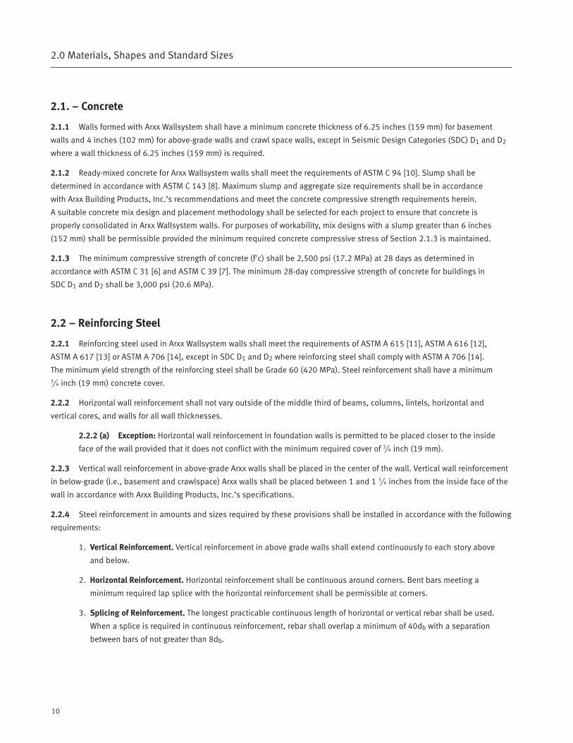
2.1. – Concrete
2.1.1 Walls formed with Arxx Wallsystem shall have a minimum concrete thickness of 6.25 inches (159 mm) for basement
walls and 4 inches (102 mm) for above-grade walls and crawl space walls, except in Seismic Design Categories (SDC) D1 and D2
where a wall thickness of 6.25 inches (159 mm) is required.
2.1.2 Ready-mixed concrete for Arxx Wallsystem walls shall meet the requirements of ASTM C 94 [10]. Slump shall be
determined in accordance with ASTM C 143 [8]. Maximum slump and aggregate size requirements shall be in accordance
with Arxx Building Products, Inc.’s recommendations and meet the concrete compressive strength requirements herein.
A suitable concrete mix design and placement methodology shall be selected for each project to ensure that concrete is
properly consolidated in Arxx Wallsystem walls. For purposes of workability, mix designs with a slump greater than 6 inches
(152 mm) shall be permissible provided the minimum required concrete compressive stress of Section 2.1.3 is maintained.
2.1.3 The minimum compressive strength of concrete (f'c) shall be 2,500 psi (17.2 MPa) at 28 days as determined in
accordance with ASTM C 31 [6] and ASTM C 39 [7]. The minimum 28-day compressive strength of concrete for buildings in
SDC D1 and D2 shall be 3,000 psi (20.6 MPa).
2.2 – Reinforcing Steel
2.2.1 Reinforcing steel used in Arxx Wallsystem walls shall meet the requirements of ASTM A 615 [11], ASTM A 616 [12],
ASTM A 617 [13] or ASTM A 706 [14], except in SDC D1 and D2 where reinforcing steel shall comply with ASTM A 706 [14].
The minimum yield strength of the reinforcing steel shall be Grade 60 (420 MPa). Steel reinforcement shall have a minimum 3⁄4 inch (19 mm) concrete cover.
2.2.2 Horizontal wall reinforcement shall not vary outside of the middle third of beams, columns, lintels, horizontal and
vertical cores, and walls for all wall thicknesses.
2.2.2 (a) Exception: Horizontal wall reinforcement in foundation walls is permitted to be placed closer to the inside
face of the wall provided that it does not conflict with the minimum required cover of 3⁄4 inch (19 mm).
2.2.3 Vertical wall reinforcement in above-grade Arxx walls shall be placed in the center of the wall. Vertical wall reinforcement
in below-grade (i.e., basement and crawlspace) Arxx walls shall be placed between 1 and 1 3⁄4 inches from the inside face of the
wall in accordance with Arxx Building Products, Inc.’s specifications.
2.2.4 Steel reinforcement in amounts and sizes required by these provisions shall be installed in accordance with the following
requirements:
1. Vertical Reinforcement. Vertical reinforcement in above grade walls shall extend continuously to each story above
and below.
2. Horizontal Reinforcement. Horizontal reinforcement shall be continuous around corners. Bent bars meeting a
minimum required lap splice with the horizontal reinforcement shall be permissible at corners.
3. Splicing of Reinforcement. The longest practicable continuous length of horizontal or vertical rebar shall be used.
When a splice is required in continuous reinforcement, rebar shall overlap a minimum of 40db with a separation
between bars of not greater than 8db.
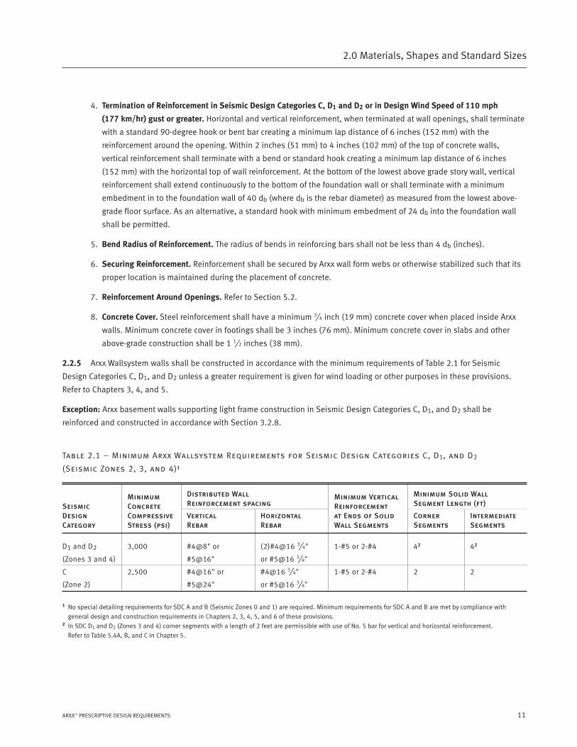
4. Termination of Reinforcement in Seismic Design Categories C, D1 and D2 or in Design Wind Speed of 110 mph
(177 km/hr) gust or greater. Horizontal and vertical reinforcement, when terminated at wall openings, shall terminate
with a standard 90-degree hook or bent bar creating a minimum lap distance of 6 inches (152 mm) with the
reinforcement around the opening. Within 2 inches (51 mm) to 4 inches (102 mm) of the top of concrete walls,
vertical reinforcement shall terminate with a bend or standard hook creating a minimum lap distance of 6 inches
(152 mm) with the horizontal top of wall reinforcement. At the bottom of the lowest above grade story wall, vertical
reinforcement shall extend continuously to the bottom of the foundation wall or shall terminate with a minimum
embedment in to the foundation wall of 40 db (where db is the rebar diameter) as measured from the lowest above-
grade floor surface. As an alternative, a standard hook with minimum embedment of 24 db into the foundation wall
shall be permitted.
5. Bend Radius of Reinforcement. The radius of bends in reinforcing bars shall not be less than 4 db (inches).
6. Securing Reinforcement. Reinforcement shall be secured by Arxx wall form webs or otherwise stabilized such that its
proper location is maintained during the placement of concrete.
7. Reinforcement Around Openings. Refer to Section 5.2.
8. Concrete Cover. Steel reinforcement shall have a minimum 3⁄4 inch (19 mm) concrete cover when placed inside Arxx
walls. Minimum concrete cover in footings shall be 3 inches (76 mm). Minimum concrete cover in slabs and other
above-grade construction shall be 1 1⁄2 inches (38 mm).
2.2.5 Arxx Wallsystem walls shall be constructed in accordance with the minimum requirements of Table 2.1 for Seismic
Design Categories C, D1, and D2 unless a greater requirement is given for wind loading or other purposes in these provisions.
Refer to Chapters 3, 4, and 5.
Exception: Arxx basement walls supporting light frame construction in Seismic Design Categories C, D1, and D2 shall be
reinforced and constructed in accordance with Section 3.2.8.
Table 2.1 – Minimum Arxx Wallsystem Requirements for Seismic Design Categories C, D1, and D2
(Seismic Zones 2, 3, and 4)1
Distributed Wall Minimum Solid WallReinforcement spacing Segment Length (ft)
Vertical Horizontal Corner IntermediateRebar Rebar Segments Segments
D1 and D2 3,000 #4@8" or (2)#4@16 3⁄4" 1-#5 or 2-#4 42 42
(Zones 3 and 4) #5@16" or #5@16 3⁄4"
C 2,500 #4@16" or #4@16 3⁄4" 1-#5 or 2-#4 2 2
(Zone 2) #5@24" or #5@16 3⁄4"
1 No special detailing requirements for SDC A and B (Seismic Zones 0 and 1) are required. Minimum requirements for SDC A and B are met by compliance with
general design and construction requirements in Chapters 2, 3, 4, 5, and 6 of these provisions.2 In SDC D1 and D2 (Zones 3 and 4) corner segments with a length of 2 feet are permissible with use of No. 5 bar for vertical and horizontal reinforcement.
Refer to Table 5.4A, B, and C in Chapter 5.
11ARXX™ PRESCRIPTIVE DESIGN REQUIREMENTS
2.0 Materials, Shapes and Standard Sizes
SeismicDesignCategory
MinimumConcreteCompressiveStress (psi)
Minimum VerticalReinforcementat Ends of SolidWall Segments
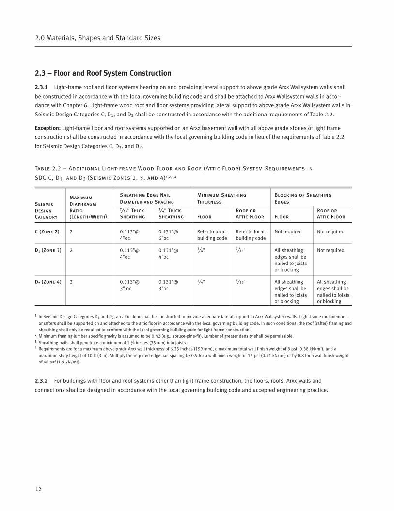
2.3 – Floor and Roof System Construction
2.3.1 Light-frame roof and floor systems bearing on and providing lateral support to above grade Arxx Wallsystem walls shall
be constructed in accordance with the local governing building code and shall be attached to Arxx Wallsystem walls in accor-
dance with Chapter 6. Light-frame wood roof and floor systems providing lateral support to above grade Arxx Wallsystem walls in
Seismic Design Categories C, D1, and D2 shall be constructed in accordance with the additional requirements of Table 2.2.
Exception: Light-frame floor and roof systems supported on an Arxx basement wall with all above grade stories of light frame
construction shall be constructed in accordance with the local governing building code in lieu of the requirements of Table 2.2
for Seismic Design Categories C, D1, and D2.
Table 2.2 – Additional Light-frame Wood Floor and Roof (Attic Floor) System Requirements in
SDC C, D1, and D2 (Seismic Zones 2, 3, and 4)1,2,3,4
Sheathing Edge Nail Minimum Sheathing Blocking of SheathingDiameter and Spacing Thickness Edges7⁄16" Thick 3⁄4" Thick Roof or Roof orSheathing Sheathing Floor Attic Floor Floor Attic Floor
C (Zone 2) 2 0.113"@ 0.131"@ Refer to local Refer to local Not required Not required4"oc 6"oc building code building code
D1 (Zone 3) 2 0.113"@ 0.131"@ 3⁄4" 7⁄16" All sheathing Not required4"oc 4"oc edges shall be
nailed to joistsor blocking
D2 (Zone 4) 2 0.113"@ 0.131"@ 3⁄4" 7⁄16" All sheathing All sheathing3" oc 3"oc edges shall be edges shall be
nailed to joists nailed to joistsor blocking or blocking
1 In Seismic Design Categories D1 and D2, an attic floor shall be constructed to provide adequate lateral support to Arxx Wallsystem walls. Light-frame roof members
or rafters shall be supported on and attached to the attic floor in accordance with the local governing building code. In such conditions, the roof (rafter) framing and
sheathing shall only be required to conform with the local governing building code for light-frame construction.2 Minimum framing lumber specific gravity is assumed to be 0.42 (e.g., spruce-pine-fir). Lumber of greater density shall be permissible.3 Sheathing nails shall penetrate a minimum of 1 3⁄8 inches (35 mm) into joists.4 Requirements are for a maximum above-grade Arxx wall thickness of 6.25 inches (159 mm), a maximum total wall finish weight of 8 psf (0.38 kN/m2), and a
maximum story height of 10 ft (3 m). Multiply the required edge nail spacing by 0.9 for a wall finish weight of 15 psf (0.71 kN/m2) or by 0.8 for a wall finish weight
of 40 psf (1.9 kN/m2).
2.3.2 For buildings with floor and roof systems other than light-frame construction, the floors, roofs, Arxx walls and
connections shall be designed in accordance with the local governing building code and accepted engineering practice.
12
2.0 Materials, Shapes and Standard Sizes
SeismicDesignCategory
MaximumDiaphragmRatio(Length/Width)
Foundations
3.0
3.1 – Footings
3.1.1 All Arxx walls shall be supported on continuous ICF, solid masonry, or concrete footings, or other approved systems of
sufficient design to safely transmit the loads imposed directly to the soil. Footings shall be supported on undisturbed natural
soil or approved fill. Footings shall be stepped where it is necessary to change the elevation of the top surface of the footings.
Minimum footing widths shall comply with Tables 3.1 and 3.2 or footings shall be designed in accordance with local building
codes, or accepted engineering practice.
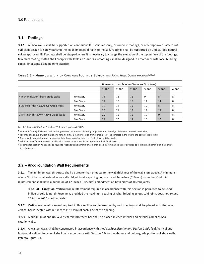
Table 3.1 – Minimum Width of Concrete Footings Supporting Arxx Wall Construction1,2,3,4,5
Minimum Load-Bearing Value of Soil (psf)
1,500 2,000 2,500 3,000 3,500 4,000
4-Inch-Thick Arxx Above-Grade Walls One Story 18 13 11 9 8 8
Two Story 24 18 15 12 11 8
6.25-Inch-Thick Arxx Above-Grade Walls One Story 19 14 12 10 8 8
Two Story 28 21 17 14 12 8
7.875-Inch-Thick Arxx Above-Grade Walls One Story 20 15 12 10 9 8
Two Story 31 23 19 16 14 8
For SI: 1 foot = 0.3048 m; 1 inch = 25.4 mm; 1 psf = 47.88 Pa1 Minimum footing thickness shall be the greater of the amount of footing projection from the edge of the concrete wall or 6 inches.2 Footings shall have a width that allows for a nominal 2-inch projection from either face of the concrete in the wall to the edge of the footing.3 For concrete foundation walls supporting light frame construction, refer to the local building code.4 Table includes foundation wall dead load assumed to be 7.875 inches (200 mm) thick for all cases.5 Concrete foundation walls shall be keyed to footings using a minimum 1.5-inch deep by 3-inch wide key or doweled to footings using minimum #4 bars at
4 feet on center.
3.2 – Arxx Foundation Wall Requirements
3.2.1 The minimum wall thickness shall be greater than or equal to the wall thickness of the wall story above. A minimum
of one No. 4 bar shall extend across all cold joints at a spacing not to exceed 24 inches (610 mm) on center. Cold joint
reinforcement shall have a minimum of 12 inches (305 mm) embedment on both sides of all cold joints.
3.2.1 (a) Exception: Vertical wall reinforcement required in accordance with this section is permitted to be used
in lieu of cold joint reinforcement, provided the maximum spacing of rebar bridging across cold joints does not exceed
24 inches (610 mm) on center.
3.2.2 Vertical wall reinforcement required in this section and interrupted by wall openings shall be placed such that one
vertical bar is located within 6 inches (152 mm) of each side of the opening.
3.2.3 A minimum of one No. 4 vertical reinforcement bar shall be placed in each interior and exterior corner of Arxx
exterior walls.
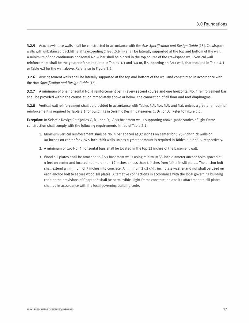
3.2.4 Arxx stem walls shall be constructed in accordance with the Arxx Specification and Design Guide [15]. Vertical and
horizontal wall reinforcement shall be in accordance with Section 4.0 for the above- and below-grade portions of stem walls.
Refer to Figure 3.1.
16
3.0 Foundations
17ARXX™ PRESCRIPTIVE DESIGN REQUIREMENTS
3.0 Foundations
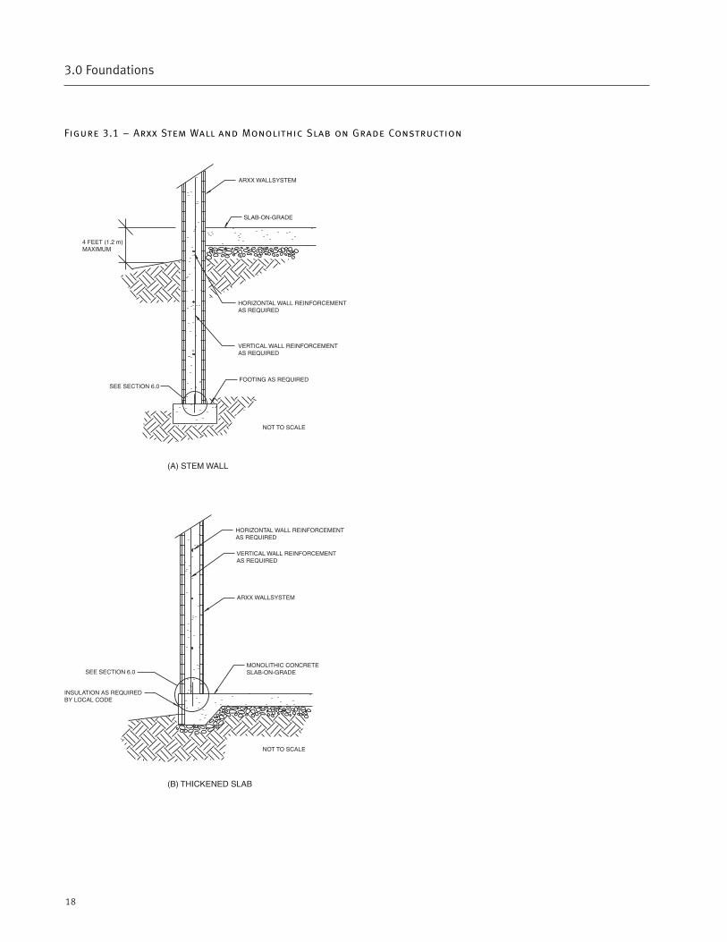
3.2.5 Arxx crawlspace walls shall be constructed in accordance with the Arxx Specification and Design Guide [15]. Crawlspace
walls with unbalanced backfill heights exceeding 2 feet (0.6 m) shall be laterally supported at the top and bottom of the wall.
A minimum of one continuous horizontal No. 4 bar shall be placed in the top course of the crawlspace wall. Vertical wall
reinforcement shall be the greater of that required in Tables 3.3 and 3.4 or, if supporting an Arxx wall, that required in Table 4.1
or Table 4.2 for the wall above. Refer also to Figure 3.2.
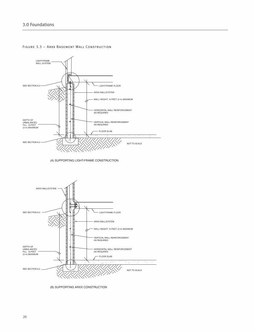
3.2.6 Arxx basement walls shall be laterally supported at the top and bottom of the wall and constructed in accordance with
the Arxx Specification and Design Guide [15].
3.2.7 A minimum of one horizontal No. 4 reinforcement bar in every second course and one horizontal No. 4 reinforcement bar
shall be provided within the course at, or immediately above or below, the connection of all floor and roof diaphragms.
3.2.8 Vertical wall reinforcement shall be provided in accordance with Tables 3.3, 3.4, 3.5, and 3.6, unless a greater amount of
reinforcement is required by Table 2.1 for buildings in Seismic Design Categories C, D1, or D2. Refer to Figure 3.3.
Exception: In Seismic Design Categories C, D1, and D2, Arxx basement walls supporting above-grade stories of light frame
construction shall comply with the following requirements in lieu of Table 2.1:
1. Minimum vertical reinforcement shall be No. 4 bar spaced at 32 inches on center for 6.25-inch-thick walls or
48 inches on center for 7.875-inch-thick walls unless a greater amount is required in Tables 3.5 or 3.6, respectively.
2. A minimum of two No. 4 horizontal bars shall be located in the top 12 inches of the basement wall.
3. Wood sill plates shall be attached to Arxx basement walls using minimum 1⁄2 inch diameter anchor bolts spaced at
4 feet on center and located not more than 12 inches or less than 4 inches from joints in sill plates. The anchor bolt
shall extend a minimum of 7 inches into concrete. A minimum 2 x 2 x 3⁄16 inch plate washer and nut shall be used on
each anchor bolt to secure wood sill plates. Alternative connections in accordance with the local governing building
code or the provisions of Chapter 6 shall be permissible. Light-frame construction and its attachment to sill plates
shall be in accordance with the local governing building code.
18
3.0 Foundations
Figure 3.1 – Arxx Stem Wall and Monolithic Slab on Grade Construction
19ARXX™ PRESCRIPTIVE DESIGN REQUIREMENTS
3.0 Foundations
Figure 3.2 – Arxx Crawlspace Construction
20
3.0 Foundations
Figure 3.3 – Arxx Basement Wall Construction
21ARXX™ PRESCRIPTIVE DESIGN REQUIREMENTS
3.0 Foundations
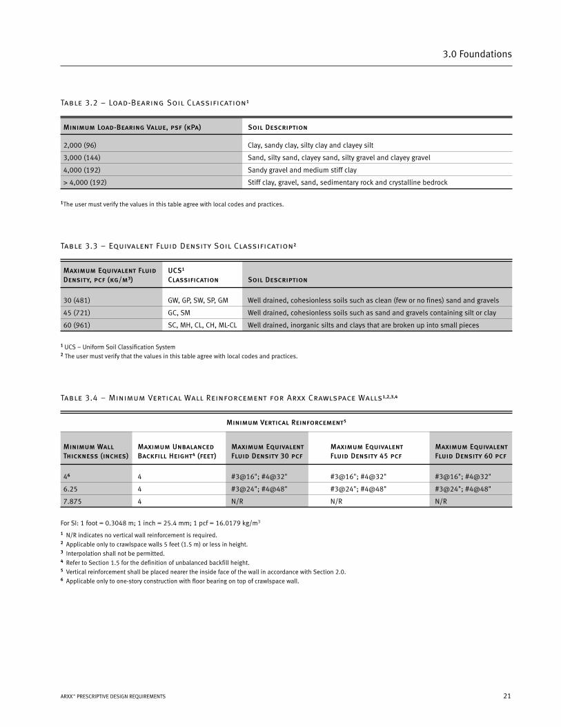
Table 3.2 – Load-Bearing Soil Classification1
Minimum Load-Bearing Value, psf (kPa) Soil Description
2,000 (96) Clay, sandy clay, silty clay and clayey silt
3,000 (144) Sand, silty sand, clayey sand, silty gravel and clayey gravel
4,000 (192) Sandy gravel and medium stiff clay
> 4,000 (192) Stiff clay, gravel, sand, sedimentary rock and crystalline bedrock
1The user must verify the values in this table agree with local codes and practices.
Table 3.3 – Equivalent Fluid Density Soil Classification2
Maximum Equivalent Fluid UCS1
Density, pcf (kg/m3) Classification Soil Description
30 (481) GW, GP, SW, SP, GM Well drained, cohesionless soils such as clean (few or no fines) sand and gravels
45 (721) GC, SM Well drained, cohesionless soils such as sand and gravels containing silt or clay
60 (961) SC, MH, CL, CH, ML-CL Well drained, inorganic silts and clays that are broken up into small pieces
1 UCS – Uniform Soil Classification System2 The user must verify that the values in this table agree with local codes and practices.
Table 3.4 – Minimum Vertical Wall Reinforcement for Arxx Crawlspace Walls1,2,3,4
Minimum Vertical Reinforcement5
Minimum Wall Maximum Unbalanced Maximum Equivalent Maximum Equivalent Maximum EquivalentThickness (inches) Backfill Height4 (feet) Fluid Density 30 pcf Fluid Density 45 pcf Fluid Density 60 pcf
46 4 #3@16"; #4@32" #3@16"; #4@32" #3@16"; #4@32"
6.25 4 #3@24"; #4@48" #3@24"; #4@48" #3@24"; #4@48"
7.875 4 N/R N/R N/R
For SI: 1 foot = 0.3048 m; 1 inch = 25.4 mm; 1 pcf = 16.0179 kg/m3
1 N/R indicates no vertical wall reinforcement is required.2 Applicable only to crawlspace walls 5 feet (1.5 m) or less in height.3 Interpolation shall not be permitted.4 Refer to Section 1.5 for the definition of unbalanced backfill height.5 Vertical reinforcement shall be placed nearer the inside face of the wall in accordance with Section 2.0.6 Applicable only to one-story construction with floor bearing on top of crawlspace wall.
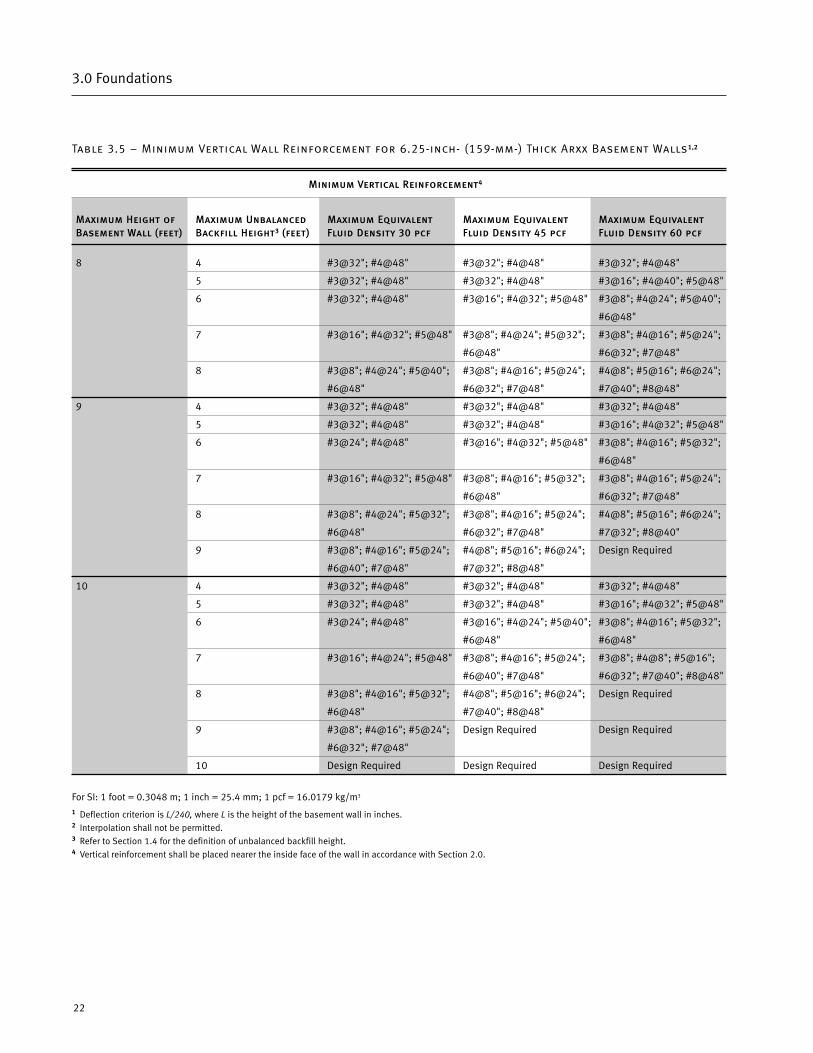
Table 3.5 – Minimum Vertical Wall Reinforcement for 6.25-inch- (159-mm-) Thick Arxx Basement Walls1,2
Minimum Vertical Reinforcement4
Maximum Height of Maximum Unbalanced Maximum Equivalent Maximum Equivalent Maximum EquivalentBasement Wall (feet) Backfill Height3 (feet) Fluid Density 30 pcf Fluid Density 45 pcf Fluid Density 60 pcf
8 4 #3@32"; #4@48" #3@32"; #4@48" #3@32"; #4@48"
5 #3@32"; #4@48" #3@32"; #4@48" #3@16"; #4@40"; #5@48"
6 #3@32"; #4@48" #3@16"; #4@32"; #5@48" #3@8"; #4@24"; #5@40";
#6@48"
7 #3@16"; #4@32"; #5@48" #3@8"; #4@24"; #5@32"; #3@8"; #4@16"; #5@24";
#6@48" #6@32"; #7@48"
8 #3@8"; #4@24"; #5@40"; #3@8"; #4@16"; #5@24"; #4@8"; #5@16"; #6@24";
#6@48" #6@32"; #7@48" #7@40"; #8@48"
9 4 #3@32"; #4@48" #3@32"; #4@48" #3@32"; #4@48"
5 #3@32"; #4@48" #3@32"; #4@48" #3@16"; #4@32"; #5@48"
6 #3@24"; #4@48" #3@16"; #4@32"; #5@48" #3@8"; #4@16"; #5@32";
#6@48"
7 #3@16"; #4@32"; #5@48" #3@8"; #4@16"; #5@32"; #3@8"; #4@16"; #5@24";
#6@48" #6@32"; #7@48"
8 #3@8"; #4@24"; #5@32"; #3@8"; #4@16"; #5@24"; #4@8"; #5@16"; #6@24";
#6@48" #6@32"; #7@48" #7@32"; #8@40"
9 #3@8"; #4@16"; #5@24"; #4@8"; #5@16"; #6@24"; Design Required
#6@40"; #7@48" #7@32"; #8@48"
10 4 #3@32"; #4@48" #3@32"; #4@48" #3@32"; #4@48"
5 #3@32"; #4@48" #3@32"; #4@48" #3@16"; #4@32"; #5@48"
6 #3@24"; #4@48" #3@16"; #4@24"; #5@40"; #3@8"; #4@16"; #5@32";
#6@48" #6@48"
7 #3@16"; #4@24"; #5@48" #3@8"; #4@16"; #5@24"; #3@8"; #4@8"; #5@16";
#6@40"; #7@48" #6@32"; #7@40"; #8@48"
8 #3@8"; #4@16"; #5@32"; #4@8"; #5@16"; #6@24"; Design Required
#6@48" #7@40"; #8@48"
9 #3@8"; #4@16"; #5@24"; Design Required Design Required
#6@32"; #7@48"
10 Design Required Design Required Design Required
For SI: 1 foot = 0.3048 m; 1 inch = 25.4 mm; 1 pcf = 16.0179 kg/m3
1 Deflection criterion is L/240, where L is the height of the basement wall in inches.2 Interpolation shall not be permitted.3 Refer to Section 1.4 for the definition of unbalanced backfill height.4 Vertical reinforcement shall be placed nearer the inside face of the wall in accordance with Section 2.0.
22
3.0 Foundations
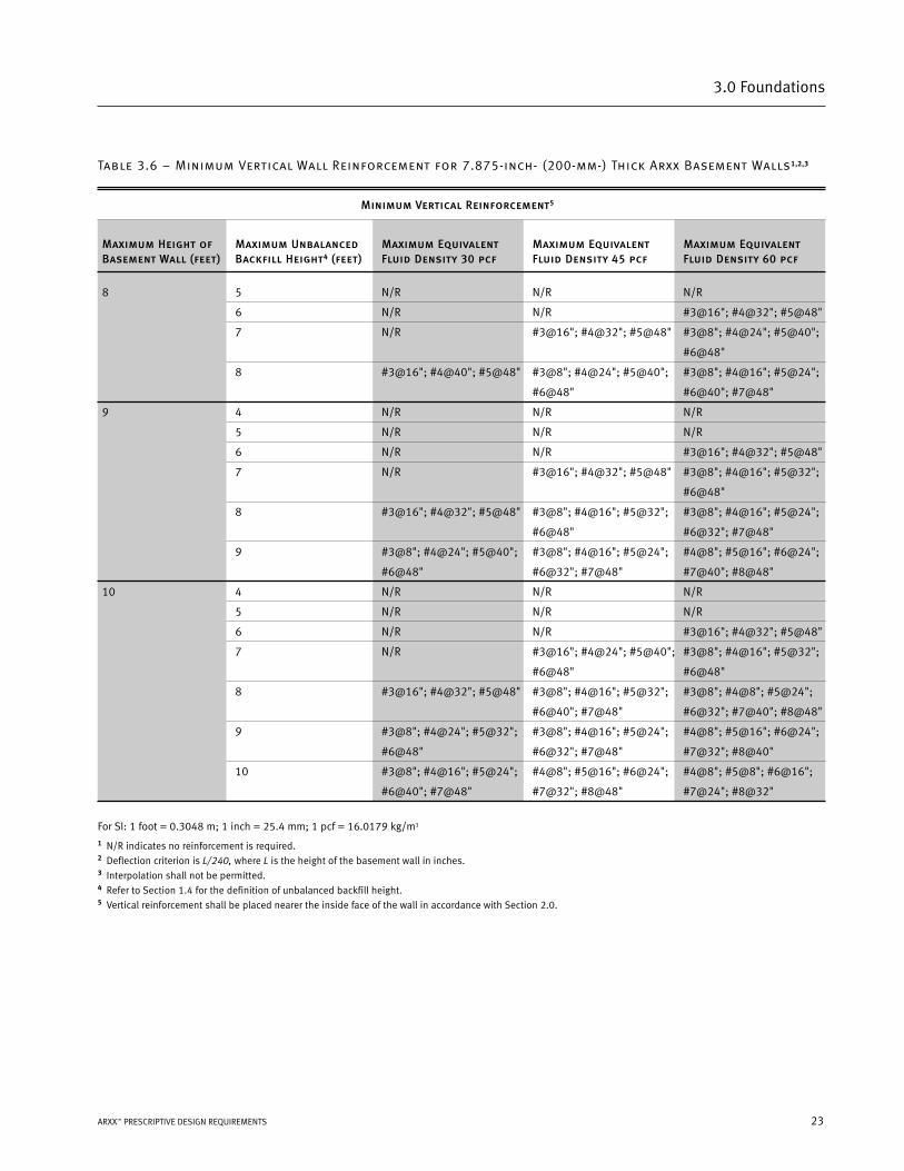
Table 3.6 – Minimum Vertical Wall Reinforcement for 7.875-inch- (200-mm-) Thick Arxx Basement Walls1,2,3
Minimum Vertical Reinforcement5
Maximum Height of Maximum Unbalanced Maximum Equivalent Maximum Equivalent Maximum EquivalentBasement Wall (feet) Backfill Height4 (feet) Fluid Density 30 pcf Fluid Density 45 pcf Fluid Density 60 pcf
8 5 N/R N/R N/R
6 N/R N/R #3@16"; #4@32"; #5@48"
7 N/R #3@16"; #4@32"; #5@48" #3@8"; #4@24"; #5@40";
#6@48"
8 #3@16"; #4@40"; #5@48" #3@8"; #4@24"; #5@40"; #3@8"; #4@16"; #5@24";
#6@48" #6@40"; #7@48"
9 4 N/R N/R N/R
5 N/R N/R N/R
6 N/R N/R #3@16"; #4@32"; #5@48"
7 N/R #3@16"; #4@32"; #5@48" #3@8"; #4@16"; #5@32";
#6@48"
8 #3@16"; #4@32"; #5@48" #3@8"; #4@16"; #5@32"; #3@8"; #4@16"; #5@24";
#6@48" #6@32"; #7@48"
9 #3@8"; #4@24"; #5@40"; #3@8"; #4@16"; #5@24"; #4@8"; #5@16"; #6@24";
#6@48" #6@32"; #7@48" #7@40"; #8@48"
10 4 N/R N/R N/R
5 N/R N/R N/R
6 N/R N/R #3@16"; #4@32"; #5@48"
7 N/R #3@16"; #4@24"; #5@40"; #3@8"; #4@16"; #5@32";
#6@48" #6@48"
8 #3@16"; #4@32"; #5@48" #3@8"; #4@16"; #5@32"; #3@8"; #4@8"; #5@24";
#6@40"; #7@48" #6@32"; #7@40"; #8@48"
9 #3@8"; #4@24"; #5@32"; #3@8"; #4@16"; #5@24"; #4@8"; #5@16"; #6@24";
#6@48" #6@32"; #7@48" #7@32"; #8@40"
10 #3@8"; #4@16"; #5@24"; #4@8"; #5@16"; #6@24"; #4@8"; #5@8"; #6@16";
#6@40"; #7@48" #7@32"; #8@48" #7@24"; #8@32"
For SI: 1 foot = 0.3048 m; 1 inch = 25.4 mm; 1 pcf = 16.0179 kg/m3
1 N/R indicates no reinforcement is required.2 Deflection criterion is L/240, where L is the height of the basement wall in inches.3 Interpolation shall not be permitted.4 Refer to Section 1.4 for the definition of unbalanced backfill height.5 Vertical reinforcement shall be placed nearer the inside face of the wall in accordance with Section 2.0.
23ARXX™ PRESCRIPTIVE DESIGN REQUIREMENTS
3.0 Foundations
Arxx™ Above-Grade Wall Requirements
4.0
26
4.0 Arxx™ Above-Grade Wall Requirements
4.1.1 Arxx above-grade walls shall be constructed in accordance with requirements in this Chapter and the additional require-
ments of Chapters 2, 5, and 6. Refer to Figures 4.1, 4.2, and 4.3.
4.1.2 A minimum of one horizontal No. 4 reinforcement bar in every second course and one horizontal No. 4 reinforcement bar
shall be provided within the course at, or immediately above or below, the connection of all floor and roof diaphragms.
4.1.3 Vertical wall reinforcement shall be provided in accordance with Tables 4.1 and 4.2 for the given wind speed unless a
greater amount is required in accordance with Table 2.1 for Seismic Design Categories C, D1, or D2.
4.1.4 The minimum wall thickness shall be greater than or equal to the wall thickness of the wall story above. A minimum of
one No. 4 bar shall extend across all cold joints at a spacing not to exceed 24 inches (610 mm) on center. Cold joint reinforce-
ment shall have a minimum of 12 inches (305 mm) embedment on both sides of all cold joints.
4.1.4 (a) Exception: Vertical wall reinforcement required in accordance with this section is permitted to be used in lieu
of cold joint reinforcement, provided the maximum spacing of rebar bridging across cold joints does not exceed
24 inches (610 mm) on center.
4.1.5 Vertical wall reinforcement required in this section and interrupted by wall openings shall be placed such that one
vertical bar is located within 6 inches (152 mm) of each side of the opening.
4.1.6 A minimum of one No. 4 vertical reinforcement bar shall be placed in each interior and exterior corner of Arxx exterior
walls.

27ARXX™ PRESCRIPTIVE DESIGN REQUIREMENTS
4.0 Arxx™ Above-Grade Wall Requirements
Figure 4.1 – Arxx Wall Supporting Light-Frame Roof
28
4.0 Arxx™ Above-Grade Wall Requirements
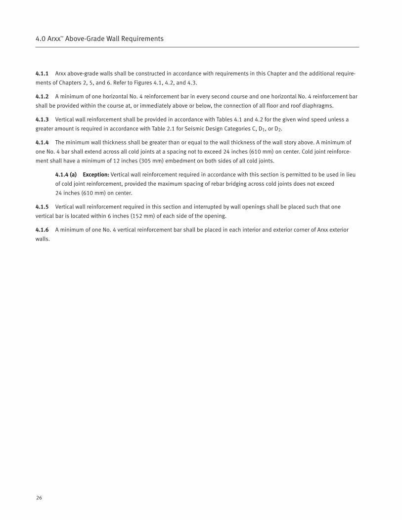
Figure 4.2 – Arxx Wall Supporting Light-Frame Second Story and Roof
29ARXX™ PRESCRIPTIVE DESIGN REQUIREMENTS
4.0 Arxx™ Above-Grade Wall Requirements
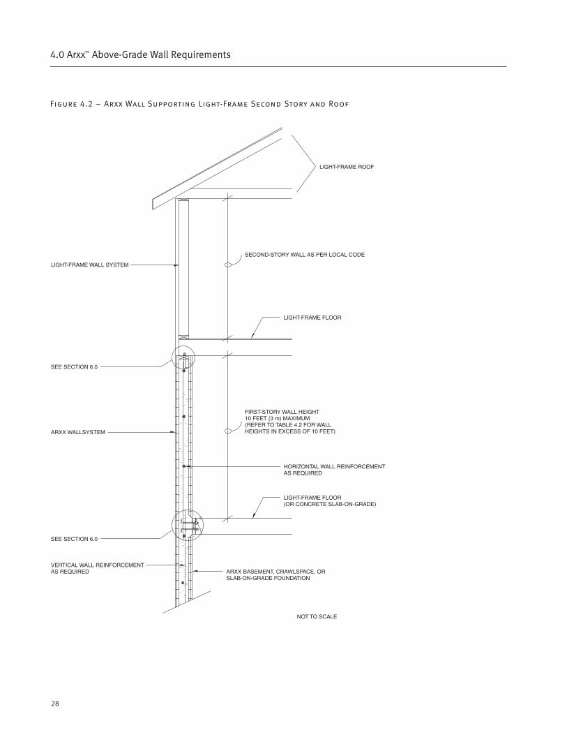
Figure 4.3 – Arxx Wall Supporting Second Story and Light-Frame Roof
30
4.0 Arxx™ Above-Grade Wall Requirements
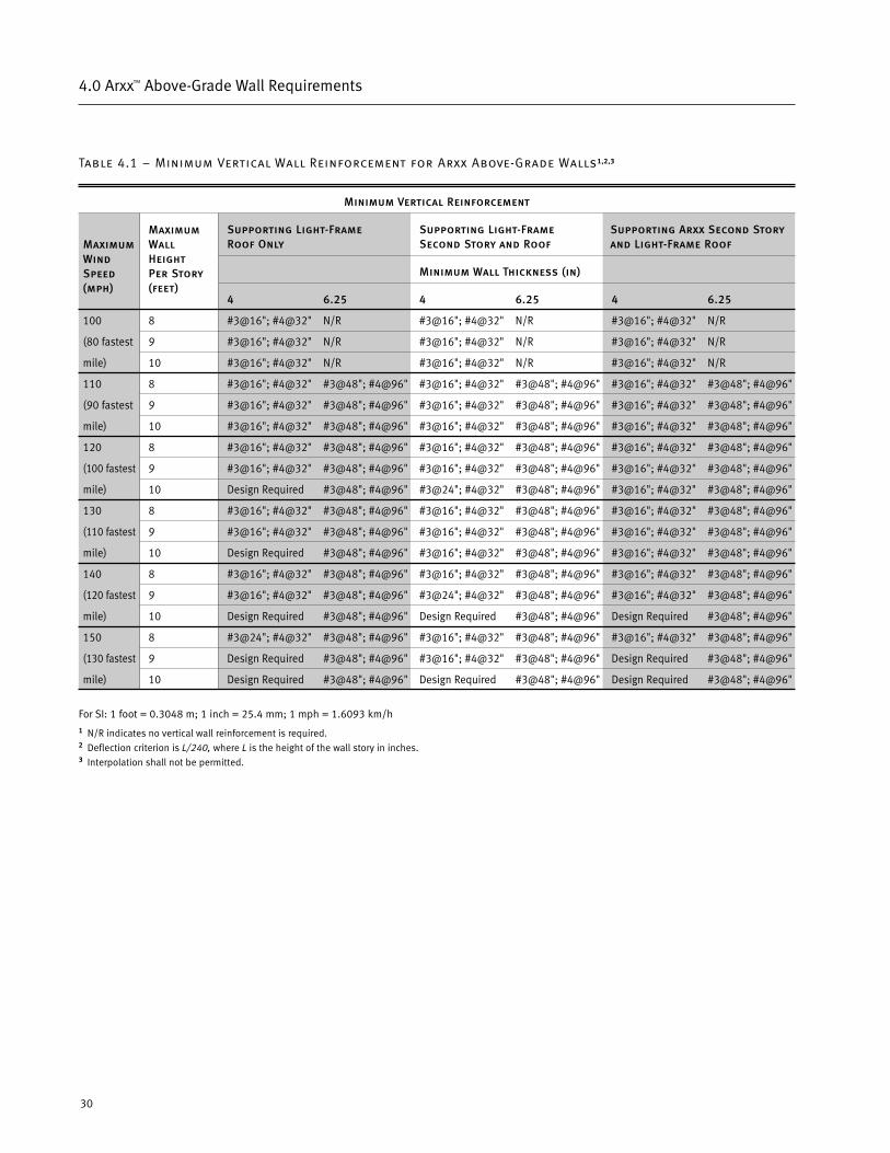
Table 4.1 – Minimum Vertical Wall Reinforcement for Arxx Above-Grade Walls1,2,3
Minimum Vertical Reinforcement
Supporting Light-Frame Supporting Light-Frame Supporting Arxx Second StoryRoof Only Second Story and Roof and Light-Frame Roof
Minimum Wall Thickness (in)
4 6.25 4 6.25 4 6.25
100 8 #3@16"; #4@32" N/R #3@16"; #4@32" N/R #3@16"; #4@32" N/R
(80 fastest 9 #3@16"; #4@32" N/R #3@16"; #4@32" N/R #3@16"; #4@32" N/R
mile) 10 #3@16"; #4@32" N/R #3@16"; #4@32" N/R #3@16"; #4@32" N/R
110 8 #3@16"; #4@32" #3@48"; #4@96" #3@16"; #4@32" #3@48"; #4@96" #3@16"; #4@32" #3@48"; #4@96"
(90 fastest 9 #3@16"; #4@32" #3@48"; #4@96" #3@16"; #4@32" #3@48"; #4@96" #3@16"; #4@32" #3@48"; #4@96"
mile) 10 #3@16"; #4@32" #3@48"; #4@96" #3@16"; #4@32" #3@48"; #4@96" #3@16"; #4@32" #3@48"; #4@96"
120 8 #3@16"; #4@32" #3@48"; #4@96" #3@16"; #4@32" #3@48"; #4@96" #3@16"; #4@32" #3@48"; #4@96"
(100 fastest 9 #3@16"; #4@32" #3@48"; #4@96" #3@16"; #4@32" #3@48"; #4@96" #3@16"; #4@32" #3@48"; #4@96"
mile) 10 Design Required #3@48"; #4@96" #3@24"; #4@32" #3@48"; #4@96" #3@16"; #4@32" #3@48"; #4@96"
130 8 #3@16"; #4@32" #3@48"; #4@96" #3@16"; #4@32" #3@48"; #4@96" #3@16"; #4@32" #3@48"; #4@96"
(110 fastest 9 #3@16"; #4@32" #3@48"; #4@96" #3@16"; #4@32" #3@48"; #4@96" #3@16"; #4@32" #3@48"; #4@96"
mile) 10 Design Required #3@48"; #4@96" #3@16"; #4@32" #3@48"; #4@96" #3@16"; #4@32" #3@48"; #4@96"
140 8 #3@16"; #4@32" #3@48"; #4@96" #3@16"; #4@32" #3@48"; #4@96" #3@16"; #4@32" #3@48"; #4@96"
(120 fastest 9 #3@16"; #4@32" #3@48"; #4@96" #3@24"; #4@32" #3@48"; #4@96" #3@16"; #4@32" #3@48"; #4@96"
mile) 10 Design Required #3@48"; #4@96" Design Required #3@48"; #4@96" Design Required #3@48"; #4@96"
150 8 #3@24"; #4@32" #3@48"; #4@96" #3@16"; #4@32" #3@48"; #4@96" #3@16"; #4@32" #3@48"; #4@96"
(130 fastest 9 Design Required #3@48"; #4@96" #3@16"; #4@32" #3@48"; #4@96" Design Required #3@48"; #4@96"
mile) 10 Design Required #3@48"; #4@96" Design Required #3@48"; #4@96" Design Required #3@48"; #4@96"
For SI: 1 foot = 0.3048 m; 1 inch = 25.4 mm; 1 mph = 1.6093 km/h1 N/R indicates no vertical wall reinforcement is required.2 Deflection criterion is L/240, where L is the height of the wall story in inches.3 Interpolation shall not be permitted.
MaximumWindSpeed(mph)
MaximumWallHeightPer Story(feet)
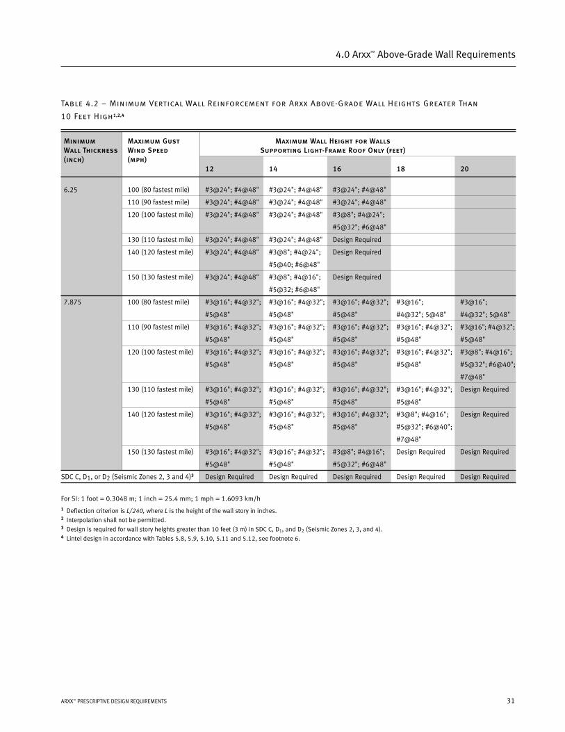
Table 4.2 – Minimum Vertical Wall Reinforcement for Arxx Above-Grade Wall Heights Greater Than
10 Feet High1,2,4
Minimum Maximum Gust Maximum Wall Height for WallsWall Thickness Wind Speed Supporting Light-Frame Roof Only (feet)(inch) (mph)
12 14 16 18 20
6.25 100 (80 fastest mile) #3@24"; #4@48" #3@24"; #4@48" #3@24"; #4@48"
110 (90 fastest mile) #3@24"; #4@48" #3@24"; #4@48" #3@24"; #4@48"
120 (100 fastest mile) #3@24"; #4@48" #3@24"; #4@48" #3@8"; #4@24";
#5@32"; #6@48"
130 (110 fastest mile) #3@24"; #4@48" #3@24"; #4@48" Design Required
140 (120 fastest mile) #3@24"; #4@48" #3@8"; #4@24"; Design Required
#5@40; #6@48"
150 (130 fastest mile) #3@24"; #4@48" #3@8"; #4@16"; Design Required
#5@32; #6@48"
7.875 100 (80 fastest mile) #3@16"; #4@32"; #3@16"; #4@32"; #3@16"; #4@32"; #3@16"; #3@16";
#5@48" #5@48" #5@48" #4@32"; 5@48" #4@32"; 5@48"
110 (90 fastest mile) #3@16"; #4@32"; #3@16"; #4@32"; #3@16"; #4@32"; #3@16"; #4@32"; #3@16"; #4@32";
#5@48" #5@48" #5@48" #5@48" #5@48"
120 (100 fastest mile) #3@16"; #4@32"; #3@16"; #4@32"; #3@16"; #4@32"; #3@16"; #4@32"; #3@8"; #4@16";
#5@48" #5@48" #5@48" #5@48" #5@32"; #6@40";
#7@48"
130 (110 fastest mile) #3@16"; #4@32"; #3@16"; #4@32"; #3@16"; #4@32"; #3@16"; #4@32"; Design Required
#5@48" #5@48" #5@48" #5@48"
140 (120 fastest mile) #3@16"; #4@32"; #3@16"; #4@32"; #3@16"; #4@32"; #3@8"; #4@16"; Design Required
#5@48" #5@48" #5@48" #5@32"; #6@40";
#7@48"
150 (130 fastest mile) #3@16"; #4@32"; #3@16"; #4@32"; #3@8"; #4@16"; Design Required Design Required
#5@48" #5@48" #5@32"; #6@48"
SDC C, D1, or D2 (Seismic Zones 2, 3 and 4)3 Design Required Design Required Design Required Design Required Design Required
For SI: 1 foot = 0.3048 m; 1 inch = 25.4 mm; 1 mph = 1.6093 km/h1 Deflection criterion is L/240, where L is the height of the wall story in inches.2 Interpolation shall not be permitted.3 Design is required for wall story heights greater than 10 feet (3 m) in SDC C, D1, and D2 (Seismic Zones 2, 3, and 4).4 Lintel design in accordance with Tables 5.8, 5.9, 5.10, 5.11 and 5.12, see footnote 6.
31ARXX™ PRESCRIPTIVE DESIGN REQUIREMENTS
4.0 Arxx™ Above-Grade Wall Requirements
Arxx™ Minimum Solid Wall Lengthand Wall-Opening Requirements
5.0
34
5.0 Arxx™ Minimum Solid Wall Length and Wall-Opening Requirements
5.1 – Minimum Length of Arxx Wall Without Openings
5.1.1 Exterior Arxx walls shall have a minimum solid wall length in accordance with this section and Tables 5.1, 5.2, 5.3, and
5.4A-C. The minimum solid wall length determined in Tables 5.1, 5.2, 5.3, and 5.4A-C shall include only those solid wall length
segments that are a minimum 2 feet (0.6 m) in length where the adjacent opening is 8 feet (2.4 m) or less in height. When the
adjacent opening is more than 8 feet (2.4 m) in height, the minimum segment length shall be in accordance with Section 5.1.2.
Minimum solid wall length segments shall not be spaced greater than 18 feet (5.5 m) on center or 16' 4" (4.98 m) edge to edge.
Minimum solid wall length segments shall extend the full height of each wall story and shall occur within 8 feet (2.4 m) of all
interior and exterior corners of exterior walls. In SDC C, D1, and D2, corner segments shall be provided and minimum wall
segment lengths shall comply with Table 2.1.
5.1.2 Maximum opening height adjacent to solid wall segments considered in meeting the solid wall length requirements of
Section 5.1.1 shall not be greater than the wall segment length multiplied by 4. In SDC D1 and D2, maximum wall opening height
shall be 8 feet (2.4 m). Openings that are stacked shall be separated by a minimum 12 inches (0.3 m) of solid wall height.
5.1.3 The minimum solid wall amount required shall be the maximum of the following:
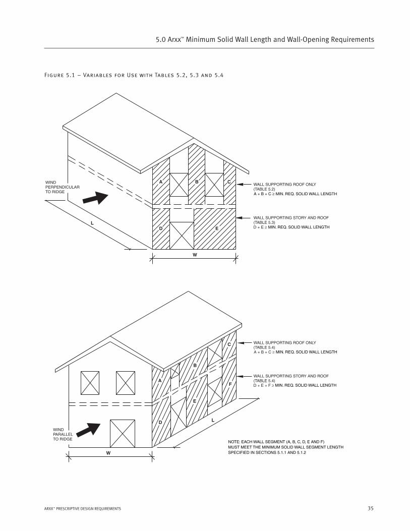
(a) Minimum solid wall length determined in accordance with Tables 5.1, 5.2, or 5.3 for building walls based on wind
loading. Refer to Figure 5.1.
(b) Minimum solid wall length determined in accordance with Tables 5.4A, B, or C for all building walls based on seismic
loading for buildings in SDC C, D1, and D2 (Seismic Zones 2, 3, and 4). Refer to Figure 5.2
(c) Minimum solid wall length based on minimum solid wall segment spacing and length requirements in Sections 5.1.1
and 5.1.2.
5.1.4 Where an interior wall is constructed as required for exterior Arxx Wallsystems including foundation requirements of
Chapter 3 and connection requirements of Chapter 6, the amount of solid wall length for the interior wall and exterior walls shall
be determined as though two separate buildings are joined at the shared interior wall line. The exterior wall amount for each of
the separate building part shall be determined using the maximum and minimum plan dimensions appropriate or each part. The
amount of solid wall required for the interior shared wall line shall be the sum of that required for the exterior wall lines for each
separate building part.
Example: A two-story 30x60 building shares a wall with an attached 20x20 single story garage on its 30-foot side. The wall
thickness is 6.25 inches and the Seismic Design Category is C. The lower story of the 30x60 building requires 11.3 feet of solid
wall in its exterior walls (Table 5.5B) and the 20x20 single story garage requires 4 feet of solid wall (Table 5.5A) in its exterior
walls. Thus, the 30-foot shared wall will require 11.3 feet + 4 feet = 15.3 feet of solid wall.
35ARXX™ PRESCRIPTIVE DESIGN REQUIREMENTS
5.0 Arxx™ Minimum Solid Wall Length and Wall-Opening Requirements
Figure 5.1 – Variables for Use with Tables 5.2, 5.3 and 5.4

36
5.0 Arxx™ Minimum Solid Wall Length and Wall-Opening Requirements
FIGURE 5.2 – Variables for Use with Tables 5.4A-C
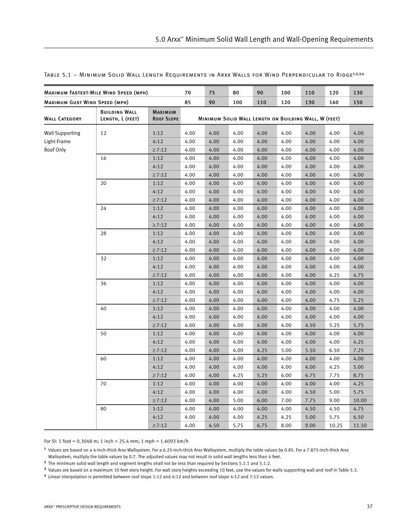
Table 5.1 – Minimum Solid Wall Length Requirements in Arxx Walls for Wind Perpendicular to Ridge1,2,3,4
Maximum Fastest-Mile Wind Speed (mph) 70 75 80 90 100 110 120 130
Maximum Gust Wind Speed (mph) 85 90 100 110 120 130 140 150
Building Wall MaximumWall Category Length, L (feet) Roof Slope Minimum Solid Wall Length on Building Wall, W (feet)
Wall Supporting 12 1:12 4.00 4.00 4.00 4.00 4.00 4.00 4.00 4.00
Light-Frame 4:12 4.00 4.00 4.00 4.00 4.00 4.00 4.00 4.00
Roof Only ≥ 7:12 4.00 4.00 4.00 4.00 4.00 4.00 4.00 4.00
16 1:12 4.00 4.00 4.00 4.00 4.00 4.00 4.00 4.00
4:12 4.00 4.00 4.00 4.00 4.00 4.00 4.00 4.00
≥ 7:12 4.00 4.00 4.00 4.00 4.00 4.00 4.00 4.00
20 1:12 4.00 4.00 4.00 4.00 4.00 4.00 4.00 4.00
4:12 4.00 4.00 4.00 4.00 4.00 4.00 4.00 4.00
≥ 7:12 4.00 4.00 4.00 4.00 4.00 4.00 4.00 4.00
24 1:12 4.00 4.00 4.00 4.00 4.00 4.00 4.00 4.00
4:12 4.00 4.00 4.00 4.00 4.00 4.00 4.00 4.00
≥ 7:12 4.00 4.00 4.00 4.00 4.00 4.00 4.00 4.00
28 1:12 4.00 4.00 4.00 4.00 4.00 4.00 4.00 4.00
4:12 4.00 4.00 4.00 4.00 4.00 4.00 4.00 4.00
≥ 7:12 4.00 4.00 4.00 4.00 4.00 4.00 4.00 4.00
32 1:12 4.00 4.00 4.00 4.00 4.00 4.00 4.00 4.00
4:12 4.00 4.00 4.00 4.00 4.00 4.00 4.00 4.00
≥ 7:12 4.00 4.00 4.00 4.00 4.00 4.00 4.25 4.75
36 1:12 4.00 4.00 4.00 4.00 4.00 4.00 4.00 4.00
4:12 4.00 4.00 4.00 4.00 4.00 4.00 4.00 4.00
≥ 7:12 4.00 4.00 4.00 4.00 4.00 4.00 4.75 5.25
40 1:12 4.00 4.00 4.00 4.00 4.00 4.00 4.00 4.00
4:12 4.00 4.00 4.00 4.00 4.00 4.00 4.00 4.00
≥ 7:12 4.00 4.00 4.00 4.00 4.00 4.50 5.25 5.75
50 1:12 4.00 4.00 4.00 4.00 4.00 4.00 4.00 4.00
4:12 4.00 4.00 4.00 4.00 4.00 4.00 4.00 4.25
≥ 7:12 4.00 4.00 4.00 4.25 5.00 5.50 6.50 7.25
60 1:12 4.00 4.00 4.00 4.00 4.00 4.00 4.00 4.00
4:12 4.00 4.00 4.00 4.00 4.00 4.00 4.25 5.00
≥ 7:12 4.00 4.00 4.25 5.25 6.00 6.75 7.75 8.75
70 1:12 4.00 4.00 4.00 4.00 4.00 4.00 4.00 4.25
4:12 4.00 4.00 4.00 4.00 4.00 4.50 5.00 5.75
≥ 7:12 4.00 4.00 5.00 6.00 7.00 7.75 9.00 10.00
80 1:12 4.00 4.00 4.00 4.00 4.00 4.50 4.50 4.75
4:12 4.00 4.00 4.00 4.25 4.25 5.00 5.75 6.50
≥ 7:12 4.00 4.50 5.75 6.75 8.00 9.00 10.25 11.50
For SI: 1 foot = 0.3048 m; 1 inch = 25.4 mm; 1 mph = 1.6093 km/h1 Values are based on a 4-inch-thick Arxx Wallsystem. For a 6.25-inch-thick Arxx Wallsystem, multiply the table values by 0.85. For a 7.875-inch-thick Arxx
Wallsystem, multiply the table values by 0.7. The adjusted values may not result in solid wall lengths less than 4 feet.2 The minimum solid wall length and segment lengths shall not be less than required by Sections 5.1.1 and 5.1.2.3 Values are based on a maximum 10 feet story height. For wall story heights exceeding 10 feet, use the values for walls supporting wall and roof in Table 5.3.4 Linear interpolation is permitted between roof slope 1:12 and 4:12 and between roof slope 4:12 and 7:12 values.
37ARXX™ PRESCRIPTIVE DESIGN REQUIREMENTS
5.0 Arxx™ Minimum Solid Wall Length and Wall-Opening Requirements
38
5.0 Arxx™ Minimum Solid Wall Length and Wall-Opening Requirements
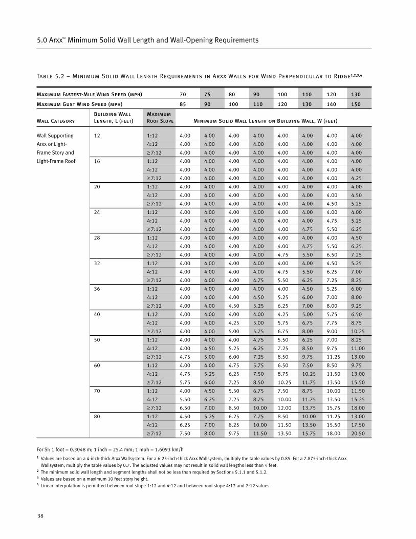
Table 5.2 – Minimum Solid Wall Length Requirements in Arxx Walls for Wind Perpendicular to Ridge1,2,3,4
Maximum Fastest-Mile Wind Speed (mph) 70 75 80 90 100 110 120 130
Maximum Gust Wind Speed (mph) 85 90 100 110 120 130 140 150
Building Wall MaximumWall Category Length, L (feet) Roof Slope Minimum Solid Wall Length on Building Wall, W (feet)
Wall Supporting 12 1:12 4.00 4.00 4.00 4.00 4.00 4.00 4.00 4.00
Arxx or Light- 4:12 4.00 4.00 4.00 4.00 4.00 4.00 4.00 4.00
Frame Story and ≥ 7:12 4.00 4.00 4.00 4.00 4.00 4.00 4.00 4.00
Light-Frame Roof 16 1:12 4.00 4.00 4.00 4.00 4.00 4.00 4.00 4.00
4:12 4.00 4.00 4.00 4.00 4.00 4.00 4.00 4.00
≥ 7:12 4.00 4.00 4.00 4.00 4.00 4.00 4.00 4.25
20 1:12 4.00 4.00 4.00 4.00 4.00 4.00 4.00 4.00
4:12 4.00 4.00 4.00 4.00 4.00 4.00 4.00 4.50
≥ 7:12 4.00 4.00 4.00 4.00 4.00 4.00 4.50 5.25
24 1:12 4.00 4.00 4.00 4.00 4.00 4.00 4.00 4.00
4:12 4.00 4.00 4.00 4.00 4.00 4.00 4.75 5.25
≥ 7:12 4.00 4.00 4.00 4.00 4.00 4.75 5.50 6.25
28 1:12 4.00 4.00 4.00 4.00 4.00 4.00 4.00 4.50
4:12 4.00 4.00 4.00 4.00 4.00 4.75 5.50 6.25
≥ 7:12 4.00 4.00 4.00 4.00 4.75 5.50 6.50 7.25
32 1:12 4.00 4.00 4.00 4.00 4.00 4.00 4.50 5.25
4:12 4.00 4.00 4.00 4.00 4.75 5.50 6.25 7.00
≥ 7:12 4.00 4.00 4.00 4.75 5.50 6.25 7.25 8.25
36 1:12 4.00 4.00 4.00 4.00 4.00 4.50 5.25 6.00
4:12 4.00 4.00 4.00 4.50 5.25 6.00 7.00 8.00
≥ 7:12 4.00 4.00 4.50 5.25 6.25 7.00 8.00 9.25
40 1:12 4.00 4.00 4.00 4.00 4.25 5.00 5.75 6.50
4:12 4.00 4.00 4.25 5.00 5.75 6.75 7.75 8.75
≥ 7:12 4.00 4.00 5.00 5.75 6.75 8.00 9.00 10.25
50 1:12 4.00 4.00 4.00 4.75 5.50 6.25 7.00 8.25
4:12 4.00 4.50 5.25 6.25 7.25 8.50 9.75 11.00
≥ 7:12 4.75 5.00 6.00 7.25 8.50 9.75 11.25 13.00
60 1:12 4.00 4.00 4.75 5.75 6.50 7.50 8.50 9.75
4:12 4.75 5.25 6.25 7.50 8.75 10.25 11.50 13.00
≥ 7:12 5.75 6.00 7.25 8.50 10.25 11.75 13.50 15.50
70 1:12 4.00 4.50 5.50 6.75 7.50 8.75 10.00 11.50
4:12 5.50 6.25 7.25 8.75 10.00 11.75 13.50 15.25
≥ 7:12 6.50 7.00 8.50 10.00 12.00 13.75 15.75 18.00
80 1:12 4.50 5.25 6.25 7.75 8.50 10.00 11.25 13.00
4:12 6.25 7.00 8.25 10.00 11.50 13.50 15.50 17.50
≥ 7:12 7.50 8.00 9.75 11.50 13.50 15.75 18.00 20.50
For SI: 1 foot = 0.3048 m; 1 inch = 25.4 mm; 1 mph = 1.6093 km/h1 Values are based on a 4-inch-thick Arxx Wallsystem. For a 6.25-inch-thick Arxx Wallsystem, multiply the table values by 0.85. For a 7.875-inch-thick Arxx
Wallsystem, multiply the table values by 0.7. The adjusted values may not result in solid wall lengths less than 4 feet.2 The minimum solid wall length and segment lengths shall not be less than required by Sections 5.1.1 and 5.1.2.3 Values are based on a maximum 10 feet story height. 4 Linear interpolation is permitted between roof slope 1:12 and 4:12 and between roof slope 4:12 and 7:12 values.
39ARXX™ PRESCRIPTIVE DESIGN REQUIREMENTS
5.0 Arxx™ Minimum Solid Wall Length and Wall-Opening Requirements
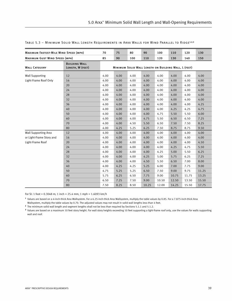
Table 5.3 – Minimum Solid Wall Length Requirements in Arxx Walls for Wind Parallel to Ridge1,2,3
Maximum Fastest-Mile Wind Speed (mph) 70 75 80 90 100 110 120 130
Maximum Gust Wind Speed (mph) 85 90 100 110 120 130 140 150
Building WallWall Category Length, W (feet) Minimum Solid Wall Length on Building Wall, L (feet)
Wall Supporting 12 4.00 4.00 4.00 4.00 4.00 4.00 4.00 4.00
Light-Frame Roof Only 16 4.00 4.00 4.00 4.00 4.00 4.00 4.00 4.00
20 4.00 4.00 4.00 4.00 4.00 4.00 4.00 4.00
24 4.00 4.00 4.00 4.00 4.00 4.00 4.00 4.00
28 4.00 4.00 4.00 4.00 4.00 4.00 4.00 4.00
32 4.00 4.00 4.00 4.00 4.00 4.00 4.00 4.00
36 4.00 4.00 4.00 4.00 4.00 4.00 4.00 4.25
40 4.00 4.00 4.00 4.00 4.00 4.25 4.25 4.75
50 4.00 4.00 4.00 4.00 4.75 5.50 5.50 6.00
60 4.00 4.00 4.00 4.75 5.50 6.50 6.50 7.25
70 4.00 4.00 4.50 5.50 6.50 7.50 7.50 8.25
80 4.00 4.25 5.25 6.25 7.50 8.75 8.75 9.50
Wall Supporting Arxx 12 4.00 4.00 4.00 4.00 4.00 4.00 4.00 4.00
or Light-Frame Story and 16 4.00 4.00 4.00 4.00 4.00 4.00 4.00 4.00
Light-Frame Roof 20 4.00 4.00 4.00 4.00 4.00 4.00 4.00 4.50
24 4.00 4.00 4.00 4.00 4.00 4.25 4.75 5.50
28 4.00 4.00 4.00 4.00 4.25 5.00 5.50 6.25
32 4.00 4.00 4.00 4.25 5.00 5.75 6.25 7.25
36 4.00 4.00 4.00 4.50 5.50 6.50 7.00 8.00
40 4.00 4.25 4.25 5.25 6.00 7.00 7.75 9.00
50 4.75 5.25 5.25 6.50 7.50 9.00 9.75 11.25
60 5.75 6.25 6.50 7.75 9.00 10.75 11.75 13.25
70 6.50 7.25 7.50 9.00 10.50 12.50 13.50 15.50
80 7.50 8.25 8.50 10.25 12.00 14.25 15.50 17.75
For SI: 1 foot = 0.3048 m; 1 inch = 25.4 mm; 1 mph = 1.6093 km/h1 Values are based on a 4-inch-thick Arxx Wallsystem. For a 6.25-inch-thick Arxx Wallsystem, multiply the table values by 0.85. For a 7.875-inch-thick Arxx
Wallsystem, multiply the table values by 0.70. The adjusted values may not result in solid wall lengths less than 4 feet.2 The minimum solid wall length and segment lengths shall not be less than required by Sections 5.1.1 and 5.1.2.3 Values are based on a maximum 10 feet story height. For wall story heights exceeding 10 feet supporting a light-frame roof only, use the values for walls supporting
wall and roof.
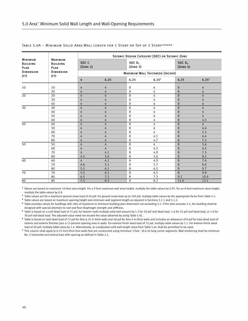
Table 5.4A – Minimum Solid Arxx Wall Length for 1 Story or Top of 2 Story1,2,3,4,5,6
Seismic Design Category (SDC) or Seismic Zone
SDC C SDC D1 SDC D2
(Zone 2) (Zone 3) (Zone 4)
Maximum Wall Thickness (Inches)
4 6.25 6.25 6.257 6.25 6.257
10 10 4 4 8 4 8 420 4 4 8 4 8 4
20 20 4 4 8 4 8 430 4 4 8 4 8 440 4 4 8 4 8 4
30 30 4 4 8 4 8 440 4 4 8 4 8 450 4 4 8 4 8 460 4 4 8 4 8 4.5
40 40 4 4 8 4 8 450 4 4 8 4 8 4.660 4 4 8 4 8 5.570 4 4 8 4.1 8 6.480 4 4 8 4.7 8 7.2
50 50 4 4 8 4 8 5.660 4 4 8 4.2 8 6.570 4 4.1 8 4.9 8 7.580 4.5 5.0 8 5.6 8 8.5
60 60 4 4.1 8 4.9 8 7.670 4.6 5.1 8 5.7 8 8.680 5.5 6.1 8 6.5 8 9.7
70 70 5.5 6.1 8 6.5 8 9.880 6.5 7.2 8 7.3 9.1 10.9
80 80 7.5 8.3 8 8.2 11.0 12.1
1 Values are based on maximum 10-foot story height. For a 9 foot maximum wall story height, multiply the table values by 0.95. For an 8-foot maximum story height,multiply the table values by 0.9.
2 Table values are for a maximum ground snow load of 40 psf. For ground snow load up to 100 psf, multiply table values by the appropriate factor from Table 5.5.3 Table values are based on maximum opening height and minimum wall segment length as required in Sections 5.1.1 and 5.1.2.4 Table provides values for buildings with ratio of maximum to minimum building plan dimension not exceeding 2:1. If the ratio exceeds 2:1, the building shall be
designed with special attention to roof and floor diaphragm strength and stiffness.5 Table is based on a roof dead load of 15 psf, for heavier roofs multiply solid wall amount by 1.3 for 20 psf roof dead load, 1.6 for 25 psf roof dead load, or 1.8 for
30 psf roof dead load. The adjusted value need not exceed the value obtained by using Table 5.4C.6 Table is based on wall dead load of 72 psf for Arxx 6.25 in thick walls and 48 psf for Arxx 4-in-thick walls and includes an allowance of 8 psf for total dead load of
interior and exterior finishes plus a 15-percent opening area in walls. For exterior finish dead load of 15 psf, multiply table values by 1.1. For exterior finish deadload of 40 psf, multiply table value by 1.4. Alternatively, an unadjusted solid wall length value from Table 5.4C shall be permitted to be used.
7 This column shall apply to 6.25-inch-thick Arxx walls that are constructed using minimum 2-foot - (0.6 m) long corner segments. Wall reinforcing shall be minimumNo. 5 horizontal and vertical bars with spacing as defined in Table 2.1.
MinimumBuildingPlanDimension(ft)
MaximumBuildingPlanDimension(ft)
40
5.0 Arxx™ Minimum Solid Wall Length and Wall-Opening Requirements
41ARXX™ PRESCRIPTIVE DESIGN REQUIREMENTS
5.0 Arxx™ Minimum Solid Wall Length and Wall-Opening Requirements
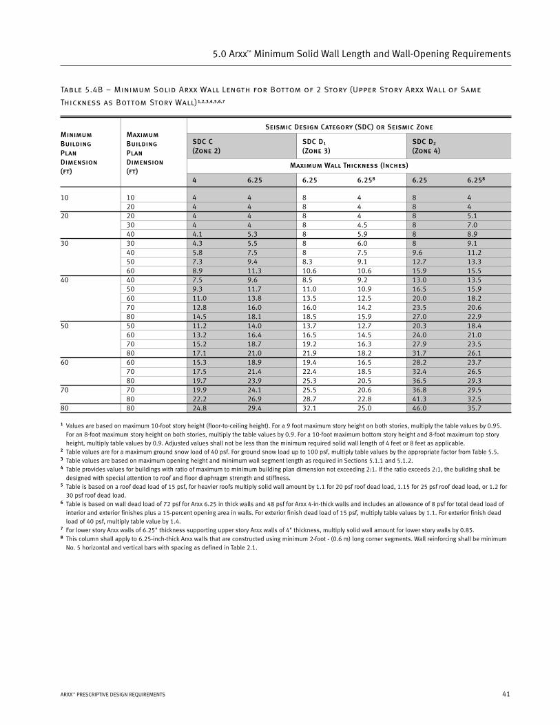
Table 5.4B – Minimum Solid Arxx Wall Length for Bottom of 2 Story (Upper Story Arxx Wall of Same
Thickness as Bottom Story Wall)1,2,3,4,5,6,7
Seismic Design Category (SDC) or Seismic Zone
SDC C SDC D1 SDC D2
(Zone 2) (Zone 3) (Zone 4)
Maximum Wall Thickness (Inches)
4 6.25 6.25 6.258 6.25 6.258
10 10 4 4 8 4 8 420 4 4 8 4 8 4
20 20 4 4 8 4 8 5.130 4 4 8 4.5 8 7.040 4.1 5.3 8 5.9 8 8.9
30 30 4.3 5.5 8 6.0 8 9.140 5.8 7.5 8 7.5 9.6 11.250 7.3 9.4 8.3 9.1 12.7 13.360 8.9 11.3 10.6 10.6 15.9 15.5
40 40 7.5 9.6 8.5 9.2 13.0 13.550 9.3 11.7 11.0 10.9 16.5 15.960 11.0 13.8 13.5 12.5 20.0 18.270 12.8 16.0 16.0 14.2 23.5 20.680 14.5 18.1 18.5 15.9 27.0 22.9
50 50 11.2 14.0 13.7 12.7 20.3 18.460 13.2 16.4 16.5 14.5 24.0 21.070 15.2 18.7 19.2 16.3 27.9 23.580 17.1 21.0 21.9 18.2 31.7 26.1
60 60 15.3 18.9 19.4 16.5 28.2 23.770 17.5 21.4 22.4 18.5 32.4 26.580 19.7 23.9 25.3 20.5 36.5 29.3
70 70 19.9 24.1 25.5 20.6 36.8 29.580 22.2 26.9 28.7 22.8 41.3 32.5
80 80 24.8 29.4 32.1 25.0 46.0 35.7
1 Values are based on maximum 10-foot story height (floor-to-ceiling height). For a 9 foot maximum story height on both stories, multiply the table values by 0.95.For an 8-foot maximum story height on both stories, multiply the table values by 0.9. For a 10-foot maximum bottom story height and 8-foot maximum top storyheight, multiply table values by 0.9. Adjusted values shall not be less than the minimum required solid wall length of 4 feet or 8 feet as applicable.
2 Table values are for a maximum ground snow load of 40 psf. For ground snow load up to 100 psf, multiply table values by the appropriate factor from Table 5.5.3 Table values are based on maximum opening height and minimum wall segment length as required in Sections 5.1.1 and 5.1.2.4 Table provides values for buildings with ratio of maximum to minimum building plan dimension not exceeding 2:1. If the ratio exceeds 2:1, the building shall be
designed with special attention to roof and floor diaphragm strength and stiffness.5 Table is based on a roof dead load of 15 psf, for heavier roofs multiply solid wall amount by 1.1 for 20 psf roof dead load, 1.15 for 25 psf roof dead load, or 1.2 for
30 psf roof dead load. 6 Table is based on wall dead load of 72 psf for Arxx 6.25 in thick walls and 48 psf for Arxx 4-in-thick walls and includes an allowance of 8 psf for total dead load of
interior and exterior finishes plus a 15-percent opening area in walls. For exterior finish dead load of 15 psf, multiply table values by 1.1. For exterior finish deadload of 40 psf, multiply table value by 1.4.
7 For lower story Arxx walls of 6.25" thickness supporting upper story Arxx walls of 4" thickness, multiply solid wall amount for lower story walls by 0.85.8 This column shall apply to 6.25-inch-thick Arxx walls that are constructed using minimum 2-foot - (0.6 m) long corner segments. Wall reinforcing shall be minimum
No. 5 horizontal and vertical bars with spacing as defined in Table 2.1.
MinimumBuildingPlanDimension(ft)
MaximumBuildingPlanDimension(ft)
42
5.0 Arxx™ Minimum Solid Wall Length and Wall-Opening Requirements
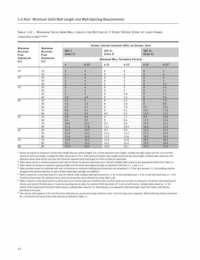
Table 5.4C – Minimum Solid Arxx Wall Length for Bottom of 2 Story (Upper Story of Light-Frame
Construction)1,2,3,4,5,6
Seismic Design Category (SDC) or Seismic Zone
SDC C SDC D1 SDC D2
(Zone 2) (Zone 3) (Zone 4)
Maximum Wall Thickness (Inches)
4 6.25 6.25 6.257 6.25 6.257
10 10 4 4 8 4 8 420 4 4 8 4 8 4
20 20 4 4 8 4 8 430 4 4 8 4 8 440 4 4 8 4 8 4.2
30 30 4 4 8 4 8 4.440 4 4 8 4 8 5.750 4 4 8 4.6 8 7.160 5.0 4.9 8 5.5 8 8.4
40 40 4.1 4 8 4.7 8 7.350 5.4 5.3 8 5.8 8 8.860 6.7 6.7 8 7.0 8.3 10.470 8.0 8.1 8 8.1 10.7 11.980 9.4 9.5 8.5 9.2 13.0 13.5
50 50 6.9 6.9 8 7.1 8.6 10.660 8.4 8.5 8 8.4 11.3 12.470 10.0 10.1 9.2 9.6 13.9 14.180 11.5 11.8 11.1 10.9 16.6 15.9
60 60 10.2 10.3 9.4 9.8 14.2 14.370 11.9 12.1 11.5 11.2 17.2 16.380 13.6 14.0 13.7 12.6 20.2 18.3
70 70 13.8 14.1 13.9 12.8 20.5 18.580 15.7 16.2 16.2 14.4 23.8 20.8
80 80 17.9 18.4 18.8 16.1 27.4 23.2
1 Values are based on maximum 10-foot story height (floor-to-ceiling height). For a 9 foot maximum story height, multiply the table values by 0.95. For an 8-footmaximum wall story height, multiply the table values by 0.9. For a 10ft maximum bottom story height and 8 foot top story height, multiply table values by 0.97.Adjusted values shall not be less than the minimum required solid wall length of 4 feet or 8 feet as applicable.
2 Table values are for a maximum ground snow load of 40 psf. For ground snow load up to 100 psf, multiply table values by the appropriate factor from Table 5.5.3 Table values are based on maximum opening height and minimum wall segment length as required in Sections 5.1.1 and 5.1.2.4 Table provides values for buildings with ratio of maximum to minimum building plan dimension not exceeding 2:1. If the ratio exceeds 2:1, the building shall be
designed with special attention to roof and floor diaphragm strength and stiffness.5 Table is based on a roof dead load of 15 psf, for heavier roofs multiply solid wall amount by 1.1 for 20 psf roof dead load, 1.2 for 25 psf roof dead load, or 1.3 for
30 psf roof dead load. The adjusted value need not exceed the value obtained by using Table 5.4B.6 Table is based on wall dead load of 72 psf for Arxx 6.25 in thick walls and 48 psf for Arxx 4-in-thick walls and includes an allowance of 8 psf for total dead load of
interior and exterior finishes plus a 15-percent opening area in walls. For exterior finish dead load of 15 psf on both stories, multiply table values by 1.2. Forexterior finish dead load of 40 psf on both stories, multiply table value by 1.6. Alternatively, an unadjusted solid wall length value from Table 5.4B shall bepermitted to be used.
7 This column shall apply to 6.25-inch-thick Arxx walls that are constructed using minimum 2-foot - (0.6 m) long corner segments. Wall reinforcing shall be minimumNo. 5 horizontal and vertical bars with spacing as defined in Table 2.1.
MinimumBuildingPlanDimension(ft)
MaximumBuildingPlanDimension(ft)
43ARXX™ PRESCRIPTIVE DESIGN REQUIREMENTS
5.0 Arxx™ Minimum Solid Wall Length and Wall-Opening Requirements
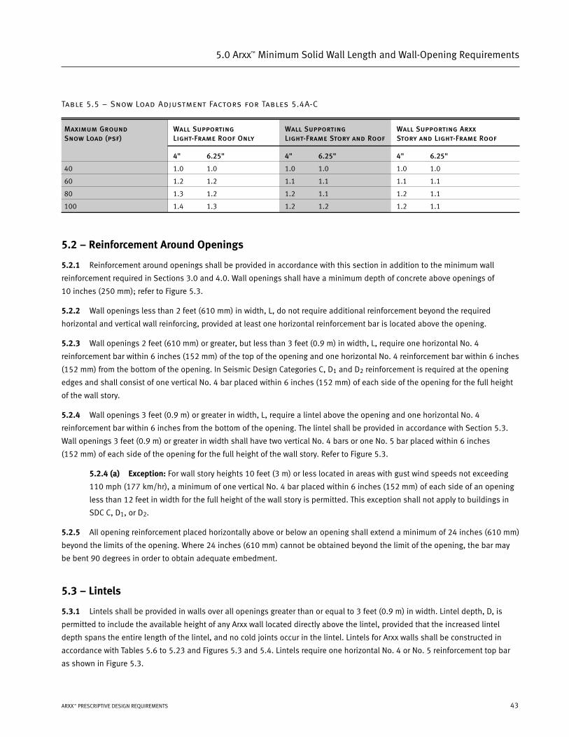
Table 5.5 – Snow Load Adjustment Factors for Tables 5.4A-C
Maximum Ground Wall Supporting Wall Supporting Wall Supporting ArxxSnow Load (psf) Light-Frame Roof Only Light-Frame Story and Roof Story and Light-Frame Roof
4" 6.25" 4" 6.25" 4" 6.25"
40 1.0 1.0 1.0 1.0 1.0 1.0
60 1.2 1.2 1.1 1.1 1.1 1.1
80 1.3 1.2 1.2 1.1 1.2 1.1
100 1.4 1.3 1.2 1.2 1.2 1.1
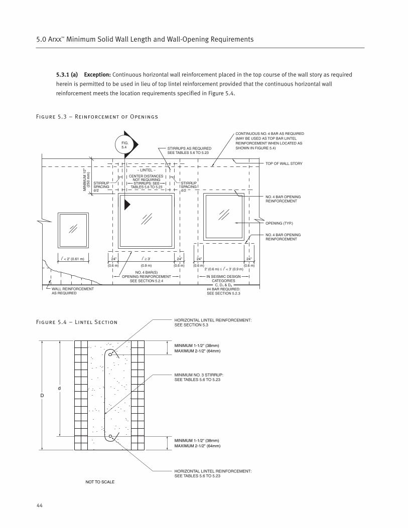
5.2 – Reinforcement Around Openings
5.2.1 Reinforcement around openings shall be provided in accordance with this section in addition to the minimum wall
reinforcement required in Sections 3.0 and 4.0. Wall openings shall have a minimum depth of concrete above openings of
10 inches (250 mm); refer to Figure 5.3.
5.2.2 Wall openings less than 2 feet (610 mm) in width, L, do not require additional reinforcement beyond the required
horizontal and vertical wall reinforcing, provided at least one horizontal reinforcement bar is located above the opening.
5.2.3 Wall openings 2 feet (610 mm) or greater, but less than 3 feet (0.9 m) in width, L, require one horizontal No. 4
reinforcement bar within 6 inches (152 mm) of the top of the opening and one horizontal No. 4 reinforcement bar within 6 inches
(152 mm) from the bottom of the opening. In Seismic Design Categories C, D1 and D2 reinforcement is required at the opening
edges and shall consist of one vertical No. 4 bar placed within 6 inches (152 mm) of each side of the opening for the full height
of the wall story.
5.2.4 Wall openings 3 feet (0.9 m) or greater in width, L, require a lintel above the opening and one horizontal No. 4
reinforcement bar within 6 inches from the bottom of the opening. The lintel shall be provided in accordance with Section 5.3.
Wall openings 3 feet (0.9 m) or greater in width shall have two vertical No. 4 bars or one No. 5 bar placed within 6 inches
(152 mm) of each side of the opening for the full height of the wall story. Refer to Figure 5.3.
5.2.4 (a) Exception: For wall story heights 10 feet (3 m) or less located in areas with gust wind speeds not exceeding
110 mph (177 km/hr), a minimum of one vertical No. 4 bar placed within 6 inches (152 mm) of each side of an opening
less than 12 feet in width for the full height of the wall story is permitted. This exception shall not apply to buildings in
SDC C, D1, or D2.
5.2.5 All opening reinforcement placed horizontally above or below an opening shall extend a minimum of 24 inches (610 mm)
beyond the limits of the opening. Where 24 inches (610 mm) cannot be obtained beyond the limit of the opening, the bar may
be bent 90 degrees in order to obtain adequate embedment.
5.3 – Lintels
5.3.1 Lintels shall be provided in walls over all openings greater than or equal to 3 feet (0.9 m) in width. Lintel depth, D, is
permitted to include the available height of any Arxx wall located directly above the lintel, provided that the increased lintel
depth spans the entire length of the lintel, and no cold joints occur in the lintel. Lintels for Arxx walls shall be constructed in
accordance with Tables 5.6 to 5.23 and Figures 5.3 and 5.4. Lintels require one horizontal No. 4 or No. 5 reinforcement top bar
as shown in Figure 5.3.
44
5.0 Arxx™ Minimum Solid Wall Length and Wall-Opening Requirements
5.3.1 (a) Exception: Continuous horizontal wall reinforcement placed in the top course of the wall story as required
herein is permitted to be used in lieu of top lintel reinforcement provided that the continuous horizontal wall
reinforcement meets the location requirements specified in Figure 5.4.
Figure 5.3 – Reinforcement of Openings
Figure 5.4 – Lintel Section

45ARXX™ PRESCRIPTIVE DESIGN REQUIREMENTS
5.0 Arxx™ Minimum Solid Wall Length and Wall-Opening Requirements
Table 5.6 – 20-60 psf – Maximum Snow Load – Lintel Supports Light-Frame Roof Only
Maximum Allowable Opening Width (ft-in) for Arxx Lintels1,2,3,4,5
Ground Snow Load
20 psf 40 psf 60 psf
Bottom Bar Requirement Bottom Bar Requirement Bottom Bar Requirement
(1) (1) (1) (2) (1) (1) (1) (2) (1) (1) (1) (2)
#4 Bar #5 Bar #6 Bar #5 Bars #4 Bar #5 Bar #6 Bar #5 Bars #4 Bar #5 Bar #6 Bar #5 Bars
24 ft 4-4 4-4 4-4 4-4 3-7 3-7 3-7 3-7 3-1 3-1 3-1 3-110 in 8-2 9-10 10-6 10-10 7-1 8-7 9-2 9-5 6-3 7-6 8-1 8-4
(36) (36) (36) (36) (27) (27) (27) (27) (21) (21) (21) (21)7-3 7-3 7-3 7-3 6-1 6-1 6-1 6-1 5-4 5-4 5-4 5-4
16 in 10-7 13-0 15-2 16-4 9-4 11-5 13-4 15-5 8-3 10-1 11-10 13-8(59) (59) (59) (59) (45) (45) (45) (45) (36) (36) (36) (36)10-9 10-9 10-9 10-9 9-3 9-3 9-3 9-3 8-1 8-1 8-1 8-1
24 in 12-10 15-10 16-4 16-4 11-4 14-0 16-4 16-4 10-2 12-6 14-9 16-4(85) (85) (85) (85) (67) (67) (67) (67) (53) (53) (53) (53)13-11 13-11 13-11 13-11 12-1 12-1 12-1 12-1 10-9 10-9 10-9 10-9
32 in 14-5 16-4 16-4 16-4 12-11 16-0 16-4 16-4 11-7 14-4 16-4 16-4(107) (107) (107) (107) (85) (85) (85) (85) (69) (69) (69) (69)
32 ft 3-8 3-8 3-8 3-8 3-1 3-1 3-1 3-1 2-8 2-8 2-8 2-810 in 7-2 8-8 9-3 9-7 6-2 7-6 8-0 8-3 5-5 6-7 7-1 7-3
(28) (28) (28) (28) (21) (21) (21) (21) (16) (16) (16) (16)6-2 6-2 6-2 6-2 5-3 5-3 5-3 5-3 4-7 4-7 4-7 4-7
16 in 9-5 11-6 13-6 15-7 8-2 10-1 11-9 13-7 7-3 8-10 10-4 12-0(46) (46) (46) (46) (35) (35) (35) (35) (27) (27) (27) (27)9-4 9-4 9-4 9-4 8-1 8-1 8-1 8-1 7-1 7-1 7-1 7-1
24 in 11-6 14-2 16-4 16-4 10-1 12-5 14-8 16-4 8-11 11-1 13-0 15-2(68) (68) (68) (68) (53) (53) (53) (53) (41) (41) (41) (41)12-3 12-3 12-3 12-3 10-8 10-8 10-8 10-8 9-6 9-6 9-6 9-6
32 in 13-0 16-1 16-4 16-4 11-7 14-3 16-4 16-4 10-3 12-9 15-0 16-4(87) (87) (87) (87) (68) (68) (68) (68) (54) (54) (54) (54)
40 ft 3-3 3-3 3-3 3-3 2-9 2-9 2-9 2-9 2-5 2-5 2-5 2-510 in 6-6 7-10 8-4 8-8 5-7 6-9 7-3 7-6 4-11 5-11 6-4 6-6
(23) (23) (23) (23) (17) (17) (17) (17) (13) (13) (13) (13)5-6 5-6 5-6 5-6 4-9 4-9 4-9 4-9 4-2 4-2 4-2 4-2
16 in 8-6 10-5 12-3 14-2 7-5 9-1 10-8 12-4 6-6 8-0 9-4 10-10(38) (38) (38) (38) (29) (29) (29) (29) (22) (22) (22) (22)8-5 8-5 8-5 8-5 7-4 7-4 7-4 7-4 6-6 6-6 6-6 6-6
24 in 10-6 12-11 15-3 16-4 9-2 11-4 13-4 15-7 8-1 10-0 11-9 13-9(57) (57) (57) (57) (44) (44) (44) (44) (34) (34) (34) (34)11-1 11-1 11-1 11-1 9-9 9-9 9-9 9-9 8-9 8-9 8-9 8-9
32 in 11-11 14-9 16-4 16-4 10-6 13-0 15-5 16-4 9-4 11-7 13-8 16-1(73) (73) (73) (73) (57) (57) (57) (57) (45) (45) (45) (45)
For SI: 1 foot = 0.3048 m; 1 inch = 25.4 mm; 1 psf = 47.8804 Pa
1 Allowable opening widths applicable for 4-inch, 6.25-inch, and 7.875-inch-wide lintels with bottom reinforcement indicated in table and No. 4 top bar reinforcement.2 Total service load deflection criterion is L/240, where L is the opening width of the lintel in inches.3 When stirrups are required, use No. 3 stirrups spaced d/2 on center (see Figures 5.3 and 5.4).4 For roof dead loads up to 25 psf, use next higher ground snow load category (e.g., 25 psf roof dead load and 20 psf ground snow load, use 40 psf ground snow load values).5 Linear interpolation allowed for intermediate Maximum Roof Span lengths and for intermediate Ground Snow Load values.
MaximumRoofSpan
MinimumLintelDepth, D
2-115-10(19)
Maximum allowable opening width (ft-in) for lintel without stirrups.
Maximum allowable opening width (ft-in) for lintel with stirrups.
Distance (inches) in center of lintel where stirrups are not required (for use with lintels with stirrups).
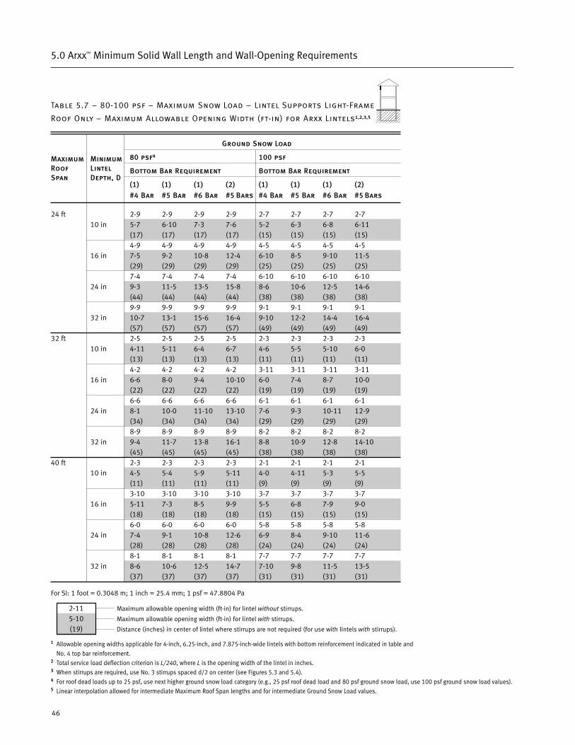
2-115-10(19)
Maximum allowable opening width (ft-in) for lintel without stirrups.
Maximum allowable opening width (ft-in) for lintel with stirrups.
Distance (inches) in center of lintel where stirrups are not required (for use with lintels with stirrups).
46
5.0 Arxx™ Minimum Solid Wall Length and Wall-Opening Requirements
Table 5.7 – 80-100 psf – Maximum Snow Load – Lintel Supports Light-Frame
Roof Only – Maximum Allowable Opening Width (ft-in) for Arxx Lintels1,2,3,5
Ground Snow Load
80 psf4 100 psf
Bottom Bar Requirement Bottom Bar Requirement
(1) (1) (1) (2) (1) (1) (1) (2)
#4 Bar #5 Bar #6 Bar #5 Bars #4 Bar #5 Bar #6 Bar #5 Bars
24 ft 2-9 2-9 2-9 2-9 2-7 2-7 2-7 2-710 in 5-7 6-10 7-3 7-6 5-2 6-3 6-8 6-11
(17) (17) (17) (17) (15) (15) (15) (15)4-9 4-9 4-9 4-9 4-5 4-5 4-5 4-5
16 in 7-5 9-2 10-8 12-4 6-10 8-5 9-10 11-5(29) (29) (29) (29) (25) (25) (25) (25)7-4 7-4 7-4 7-4 6-10 6-10 6-10 6-10
24 in 9-3 11-5 13-5 15-8 8-6 10-6 12-5 14-6(44) (44) (44) (44) (38) (38) (38) (38)9-9 9-9 9-9 9-9 9-1 9-1 9-1 9-1
32 in 10-7 13-1 15-6 16-4 9-10 12-2 14-4 16-4(57) (57) (57) (57) (49) (49) (49) (49)
32 ft 2-5 2-5 2-5 2-5 2-3 2-3 2-3 2-310 in 4-11 5-11 6-4 6-7 4-6 5-5 5-10 6-0
(13) (13) (13) (13) (11) (11) (11) (11)4-2 4-2 4-2 4-2 3-11 3-11 3-11 3-11
16 in 6-6 8-0 9-4 10-10 6-0 7-4 8-7 10-0(22) (22) (22) (22) (19) (19) (19) (19)6-6 6-6 6-6 6-6 6-1 6-1 6-1 6-1
24 in 8-1 10-0 11-10 13-10 7-6 9-3 10-11 12-9(34) (34) (34) (34) (29) (29) (29) (29)8-9 8-9 8-9 8-9 8-2 8-2 8-2 8-2
32 in 9-4 11-7 13-8 16-1 8-8 10-9 12-8 14-10(45) (45) (45) (45) (38) (38) (38) (38)
40 ft 2-3 2-3 2-3 2-3 2-1 2-1 2-1 2-110 in 4-5 5-4 5-9 5-11 4-0 4-11 5-3 5-5
(11) (11) (11) (11) (9) (9) (9) (9)3-10 3-10 3-10 3-10 3-7 3-7 3-7 3-7
16 in 5-11 7-3 8-5 9-9 5-5 6-8 7-9 9-0(18) (18) (18) (18) (15) (15) (15) (15)6-0 6-0 6-0 6-0 5-8 5-8 5-8 5-8
24 in 7-4 9-1 10-8 12-6 6-9 8-4 9-10 11-6(28) (28) (28) (28) (24) (24) (24) (24)8-1 8-1 8-1 8-1 7-7 7-7 7-7 7-7
32 in 8-6 10-6 12-5 14-7 7-10 9-8 11-5 13-5(37) (37) (37) (37) (31) (31) (31) (31)
For SI: 1 foot = 0.3048 m; 1 inch = 25.4 mm; 1 psf = 47.8804 Pa
1 Allowable opening widths applicable for 4-inch, 6.25-inch, and 7.875-inch-wide lintels with bottom reinforcement indicated in table and
No. 4 top bar reinforcement.2 Total service load deflection criterion is L/240, where L is the opening width of the lintel in inches.3 When stirrups are required, use No. 3 stirrups spaced d/2 on center (see Figures 5.3 and 5.4).4 For roof dead loads up to 25 psf, use next higher ground snow load category (e.g., 25 psf roof dead load and 80 psf ground snow load, use 100 psf ground snow load values).5 Linear interpolation allowed for intermediate Maximum Roof Span lengths and for intermediate Ground Snow Load values.
MaximumRoofSpan
MinimumLintelDepth, D

47ARXX™ PRESCRIPTIVE DESIGN REQUIREMENTS
5.0 Arxx™ Minimum Solid Wall Length and Wall-Opening Requirements
Table 5.8 – 20 psf – Maximum Snow Load – Lintel Supports Arxx Story and Light-Frame Roof
Maximum Allowable Opening Width (ft-in) for Arxx Lintels1,2,3,4,5,6,7
Maximum Floor Span
12 ft 24 ft 32 ft
Bottom Bar Requirement Bottom Bar Requirement Bottom Bar Requirement
(1) (1) (1) (2) (1) (1) (1) (2) (1) (1) (1) (2)
#4 Bar #5 Bar #6 Bar #5 Bars #4 Bar #5 Bar #6 Bar #5 Bars #4 Bar #5 Bar #6 Bar #5 Bars
24 ft 2-5 2-5 2-5 2-5 2-3 2-3 2-3 2-3 2-1 2-1 2-1 2-110 in 4-10 5-11 6-4 6-6 4-5 5-4 5-8 5-10 4-2 5-0 5-5 5-7
(13) (13) (13) (13) (11) (11) (11) (11) (9) (9) (9) (9)4-2 4-2 4-2 4-2 3-10 3-10 3-10 3-10 3-8 3-8 3-8 3-8
16 in 6-6 7-11 9-4 10-9 5-10 7-2 8-5 9-9 5-7 6-10 8-0 9-3(22) (22) (22) (22) (18) (18) (18) (18) (16) (16) (16) (16)6-6 6-6 6-6 6-6 6-0 6-0 6-0 6-0 5-9 5-9 5-9 5-9
24 in 8-1 9-11 11-9 13-8 7-4 9-1 10-8 12-5 6-11 8-7 10-1 11-10(34) (34) (34) (34) (28) (28) (28) (28) (25) (25) (25) (25)8-8 8-8 8-8 8-8 8-1 8-1 8-1 8-1 7-9 7-9 7-9 7-9
32 in 9-4 11-6 13-7 15-11 8-6 10-6 12-5 14-7 8-1 9-11 11-9 13-10(44) (44) (44) (44) (37) (37) (37) (37) (33) (33) (33) (33)
32 ft 2-4 2-4 2-4 2-4 2-2 2-2 2-2 2-2 2-1 2-1 2-1 2-110 in 4-8 5-7 6-0 6-2 4-3 5-1 5-6 5-8 4-0 4-10 5-2 5-4
(12) (12) (12) (12) (10) (10) (10) (10) (9) (9) (9) (9)4-0 4-0 4-0 4-0 3-9 3-9 3-9 3-9 3-7 3-7 3-7 3-7
16 in 6-2 7-7 8-10 10-3 5-8 6-11 8-1 9-4 5-4 6-7 7-8 8-11(20) (20) (20) (20) (17) (17) (17) (17) (15) (15) (15) (15)6-3 6-3 6-3 6-3 5-10 5-10 5-10 5-10 5-7 5-7 5-7 5-7
24 in 7-8 9-6 11-2 13-1 7-1 8-8 10-3 12-0 6-8 8-3 9-9 11-5(31) (31) (31) (31) (26) (26) (26) (26) (23) (23) (23) (23)8-4 8-4 8-4 8-4 7-10 7-10 7-10 7-10 7-7 7-7 7-7 7-7
32 in 8-11 11-0 13-0 15-3 8-2 10-1 11-11 14-0 7-9 9-7 11-4 13-4(40) (40) (40) (40) (34) (34) (34) (34) (31) (31) (31) (31)
40 ft 2-3 2-3 2-3 2-3 2-1 2-1 2-1 2-1 2-0 2-0 2-0 2-010 in 4-5 5-4 5-9 5-11 4-1 4-11 5-3 5-5 3-10 4-8 5-0 5-2
(11) (11) (11) (11) (9) (9) (9) (9) (8) (8) (8) (8)3-10 3-10 3-10 3-10 3-8 3-8 3-8 3-8 3-6 3-6 3-6 3-6
16 in 5-11 7-3 8-6 9-10 5-5 6-8 7-10 9-0 5-2 6-4 7-5 8-7(18) (18) (18) (18) (16) (16) (16) (16) (14) (14) (14) (14)6-0 6-0 6-0 6-0 5-8 5-8 5-8 5-8 5-6 5-6 5-6 5-6
24 in 7-4 9-1 10-9 12-6 6-10 8-5 9-11 11-7 6-6 8-0 9-5 11-0(28) (28) (28) (28) (24) (24) (24) (24) (22) (22) (22) (22)8-1 8-1 8-1 8-1 7-8 7-8 7-8 7-8 7-5 7-5 7-5 7-5
32 in 8-6 10-6 12-6 14-7 7-11 9-9 11-6 13-6 7-6 9-4 11-0 12-11(37) (37) (37) (37) (32) (32) (32) (32) (29) (29) (29) (29)
For SI: 1 foot = 0.3048 m; 1 inch = 25.4 mm; 1 psf = 47.8804 Pa
1 Allowable opening widths applicable for 4-inch, 6.25-inch, and 7.875-inch-wide lintels with bottom reinforcement indicated in table and No. 4 top bar reinforcement.2 Total service load deflection criterion is L/240, where L is the opening width of the lintel in inches.3 When stirrups are required, use No. 3 stirrups spaced d/2 on center (see Figures 5.3 and 5.4).4 For lintels supporting two stories of Arxx construction and a roof use Tables 5.13 - 5.17.5 Linear interpolation allowed for intermediate Maximum Roof Span lengths and for intermediate Ground Snow Load values.6 For Arxx walls designed in accordance with Table 4.2, lintels shall be designed using table values with maximum floor span of 12 feet.7 For roof dead loads up to 25 psf, use next higher ground snow load category (e.g., 25 psf roof dead load and 20 psf ground snow load, use 40 psf ground snow load values).
MaximumRoofSpan
MinimumLintelDepth, D
2-115-10(19)
Maximum allowable opening width (ft-in) for lintel without stirrups.
Maximum allowable opening width (ft-in) for lintel with stirrups.
Distance (inches) in center of lintel where stirrups are not required (for use with lintels with stirrups).
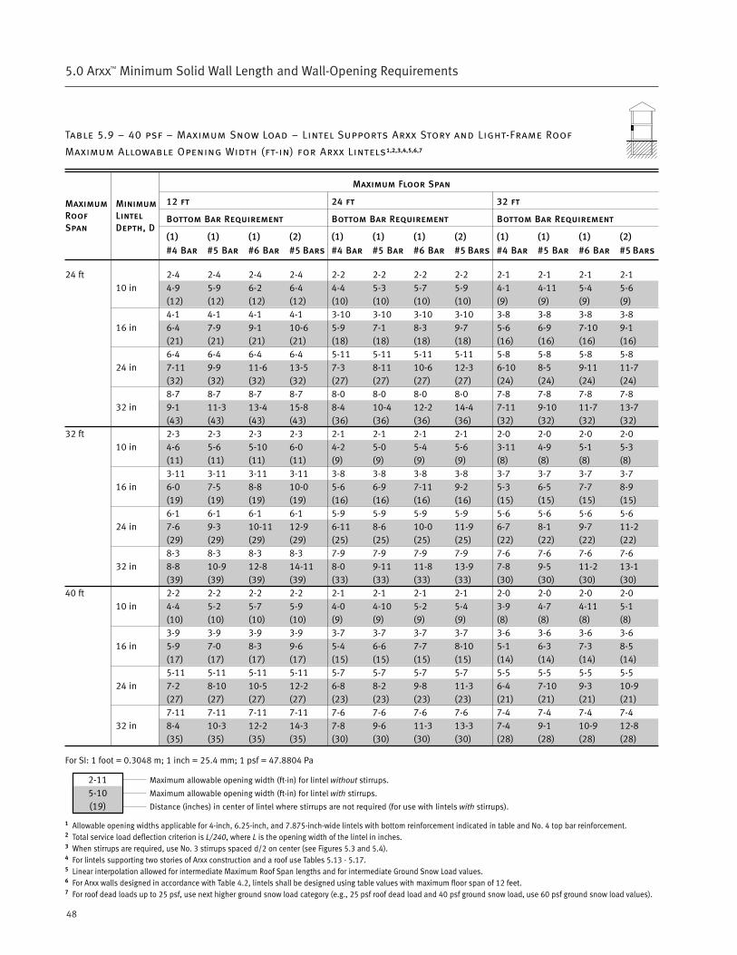
48
5.0 Arxx™ Minimum Solid Wall Length and Wall-Opening Requirements
Table 5.9 – 40 psf – Maximum Snow Load – Lintel Supports Arxx Story and Light-Frame Roof
Maximum Allowable Opening Width (ft-in) for Arxx Lintels1,2,3,4,5,6,7
Maximum Floor Span
12 ft 24 ft 32 ft
Bottom Bar Requirement Bottom Bar Requirement Bottom Bar Requirement
(1) (1) (1) (2) (1) (1) (1) (2) (1) (1) (1) (2)
#4 Bar #5 Bar #6 Bar #5 Bars #4 Bar #5 Bar #6 Bar #5 Bars #4 Bar #5 Bar #6 Bar #5 Bars
24 ft 2-4 2-4 2-4 2-4 2-2 2-2 2-2 2-2 2-1 2-1 2-1 2-110 in 4-9 5-9 6-2 6-4 4-4 5-3 5-7 5-9 4-1 4-11 5-4 5-6
(12) (12) (12) (12) (10) (10) (10) (10) (9) (9) (9) (9)4-1 4-1 4-1 4-1 3-10 3-10 3-10 3-10 3-8 3-8 3-8 3-8
16 in 6-4 7-9 9-1 10-6 5-9 7-1 8-3 9-7 5-6 6-9 7-10 9-1(21) (21) (21) (21) (18) (18) (18) (18) (16) (16) (16) (16)6-4 6-4 6-4 6-4 5-11 5-11 5-11 5-11 5-8 5-8 5-8 5-8
24 in 7-11 9-9 11-6 13-5 7-3 8-11 10-6 12-3 6-10 8-5 9-11 11-7(32) (32) (32) (32) (27) (27) (27) (27) (24) (24) (24) (24)8-7 8-7 8-7 8-7 8-0 8-0 8-0 8-0 7-8 7-8 7-8 7-8
32 in 9-1 11-3 13-4 15-8 8-4 10-4 12-2 14-4 7-11 9-10 11-7 13-7(43) (43) (43) (43) (36) (36) (36) (36) (32) (32) (32) (32)
32 ft 2-3 2-3 2-3 2-3 2-1 2-1 2-1 2-1 2-0 2-0 2-0 2-010 in 4-6 5-6 5-10 6-0 4-2 5-0 5-4 5-6 3-11 4-9 5-1 5-3
(11) (11) (11) (11) (9) (9) (9) (9) (8) (8) (8) (8)3-11 3-11 3-11 3-11 3-8 3-8 3-8 3-8 3-7 3-7 3-7 3-7
16 in 6-0 7-5 8-8 10-0 5-6 6-9 7-11 9-2 5-3 6-5 7-7 8-9(19) (19) (19) (19) (16) (16) (16) (16) (15) (15) (15) (15)6-1 6-1 6-1 6-1 5-9 5-9 5-9 5-9 5-6 5-6 5-6 5-6
24 in 7-6 9-3 10-11 12-9 6-11 8-6 10-0 11-9 6-7 8-1 9-7 11-2(29) (29) (29) (29) (25) (25) (25) (25) (22) (22) (22) (22)8-3 8-3 8-3 8-3 7-9 7-9 7-9 7-9 7-6 7-6 7-6 7-6
32 in 8-8 10-9 12-8 14-11 8-0 9-11 11-8 13-9 7-8 9-5 11-2 13-1(39) (39) (39) (39) (33) (33) (33) (33) (30) (30) (30) (30)
40 ft 2-2 2-2 2-2 2-2 2-1 2-1 2-1 2-1 2-0 2-0 2-0 2-010 in 4-4 5-2 5-7 5-9 4-0 4-10 5-2 5-4 3-9 4-7 4-11 5-1
(10) (10) (10) (10) (9) (9) (9) (9) (8) (8) (8) (8)3-9 3-9 3-9 3-9 3-7 3-7 3-7 3-7 3-6 3-6 3-6 3-6
16 in 5-9 7-0 8-3 9-6 5-4 6-6 7-7 8-10 5-1 6-3 7-3 8-5(17) (17) (17) (17) (15) (15) (15) (15) (14) (14) (14) (14)5-11 5-11 5-11 5-11 5-7 5-7 5-7 5-7 5-5 5-5 5-5 5-5
24 in 7-2 8-10 10-5 12-2 6-8 8-2 9-8 11-3 6-4 7-10 9-3 10-9(27) (27) (27) (27) (23) (23) (23) (23) (21) (21) (21) (21)7-11 7-11 7-11 7-11 7-6 7-6 7-6 7-6 7-4 7-4 7-4 7-4
32 in 8-4 10-3 12-2 14-3 7-8 9-6 11-3 13-3 7-4 9-1 10-9 12-8(35) (35) (35) (35) (30) (30) (30) (30) (28) (28) (28) (28)
For SI: 1 foot = 0.3048 m; 1 inch = 25.4 mm; 1 psf = 47.8804 Pa
1 Allowable opening widths applicable for 4-inch, 6.25-inch, and 7.875-inch-wide lintels with bottom reinforcement indicated in table and No. 4 top bar reinforcement.2 Total service load deflection criterion is L/240, where L is the opening width of the lintel in inches.3 When stirrups are required, use No. 3 stirrups spaced d/2 on center (see Figures 5.3 and 5.4).4 For lintels supporting two stories of Arxx construction and a roof use Tables 5.13 - 5.17.5 Linear interpolation allowed for intermediate Maximum Roof Span lengths and for intermediate Ground Snow Load values.6 For Arxx walls designed in accordance with Table 4.2, lintels shall be designed using table values with maximum floor span of 12 feet.7 For roof dead loads up to 25 psf, use next higher ground snow load category (e.g., 25 psf roof dead load and 40 psf ground snow load, use 60 psf ground snow load values).
MaximumRoofSpan
MinimumLintelDepth, D
2-115-10(19)
Maximum allowable opening width (ft-in) for lintel without stirrups.
Maximum allowable opening width (ft-in) for lintel with stirrups.
Distance (inches) in center of lintel where stirrups are not required (for use with lintels with stirrups).

49ARXX™ PRESCRIPTIVE DESIGN REQUIREMENTS
5.0 Arxx™ Minimum Solid Wall Length and Wall-Opening Requirements
Table 5.10 – 60 psf – Maximum Snow Load – Lintel Supports Arxx Story and Light-Frame Roof
Maximum Allowable Opening Width (ft-in) for Arxx Lintels1,2,3,4,5,6,7
Maximum Floor Span
12 ft 24 ft 32 ft
Bottom Bar Requirement Bottom Bar Requirement Bottom Bar Requirement
(1) (1) (1) (2) (1) (1) (1) (2) (1) (1) (1) (2)
#4 Bar #5 Bar #6 Bar #5 Bars #4 Bar #5 Bar #6 Bar #5 Bars #4 Bar #5 Bar #6 Bar #5 Bars
24 ft 2-3 2-3 2-3 2-3 2-2 2-2 2-2 2-2 2-1 2-1 2-1 2-110 in 4-7 5-6 5-11 6-1 4-3 5-2 5-6 5-8 4-0 4-11 5-3 5-5
(11) (11) (11) (11) (10) (10) (10) (10) (9) (9) (9) (9)4-0 4-0 4-0 4-0 3-9 3-9 3-9 3-9 3-7 3-7 3-7 3-7
16 in 6-1 7-6 8-9 10-1 5-8 7-0 8-2 9-5 5-5 6-7 7-9 8-11(20) (20) (20) (20) (17) (17) (17) (17) (15) (15) (15) (15)6-2 6-2 6-2 6-2 5-10 5-10 5-10 5-10 5-7 5-7 5-7 5-7
24 in 7-7 9-4 11-0 12-11 7-1 8-9 10-4 12-1 6-9 8-4 9-10 11-5(30) (30) (30) (30) (26) (26) (26) (26) (23) (23) (23) (23)8-3 8-3 8-3 8-3 7-11 7-11 7-11 7-11 7-7 7-7 7-7 7-7
32 in 8-9 10-10 12-10 15-1 8-3 10-2 12-0 14-1 7-10 9-8 11-5 13-5(39) (39) (39) (39) (35) (35) (35) (35) (31) (31) (31) (31)
32 ft 2-2 2-2 2-2 2-2 2-1 2-1 2-1 2-1 2-0 2-0 2-0 2-010 in 4-3 5-1 5-6 5-8 4-1 4-11 5-3 5-5 3-10 4-8 5-0 5-2
(10) (10) (10) (10) (9) (9) (9) (9) (8) (8) (8) (8)3-9 3-9 3-9 3-9 3-7 3-7 3-7 3-7 3-6 3-6 3-6 3-6
16 in 5-8 6-11 8-1 9-5 5-5 6-8 7-9 9-0 5-2 6-4 7-5 8-7(17) (17) (17) (17) (15) (15) (15) (15) (14) (14) (14) (14)5-10 5-10 5-10 5-10 5-8 5-8 5-8 5-8 5-6 5-6 5-6 5-6
24 in 7-1 8-8 10-3 12-0 6-9 8-4 9-10 11-6 6-6 8-0 9-5 11-0(26) (26) (26) (26) (24) (24) (24) (24) (22) (22) (22) (22)7-10 7-10 7-10 7-10 7-8 7-8 7-8 7-8 7-5 7-5 7-5 7-5
32 in 8-2 10-1 11-11 14-0 7-10 9-9 11-6 13-6 7-6 9-3 11-0 12-10(34) (34) (34) (34) (32) (32) (32) (32) (29) (29) (29) (29)
40 ft 2-1 2-1 2-1 2-1 2-0 2-0 2-0 2-0 2-0 2-0 2-0 2-010 in 3-11 4-9 5-1 5-3 3-10 4-8 5-0 5-1 3-8 4-6 4-10 4-11
(9) (9) (9) (9) (8) (8) (8) (8) (8) (8) (8) (8)3-7 3-7 3-7 3-7 3-6 3-6 3-6 3-6 3-5 3-5 3-5 3-5
16 in 5-4 6-6 7-7 8-9 5-1 6-3 7-4 8-6 5-0 6-1 7-1 8-3(15) (15) (15) (15) (14) (14) (14) (14) (13) (13) (13) (13)5-7 5-7 5-7 5-7 5-5 5-5 5-5 5-5 5-4 5-4 5-4 5-4
24 in 6-7 8-2 9-7 11-3 6-5 7-11 9-4 10-11 6-3 7-8 9-0 10-7(23) (23) (23) (23) (21) (21) (21) (21) (20) (20) (20) (20)7-6 7-6 7-6 7-6 7-4 7-4 7-4 7-4 7-3 7-3 7-3 7-3
32 in 7-8 9-6 11-3 13-2 7-5 9-3 10-11 12-9 7-3 8-11 10-7 12-5(30) (30) (30) (30) (28) (28) (28) (28) NR8 (27) (27) (27)
For SI: 1 foot = 0.3048 m; 1 inch = 25.4 mm; 1 psf = 47.8804 Pa
1 Allowable opening widths applicable for 4-inch, 6.25-inch, and 7.875-inch-wide lintels with bottom reinforcement indicated in table and No. 4 top bar reinforcement.2 Total service load deflection criterion is L/240, where L is the opening width of the lintel in inches.3 When stirrups are required, use No. 3 stirrups spaced d/2 on center (see Figures 5.3 and 5.4).4 For lintels supporting two stories of Arxx construction and a roof use Tables 5.13 - 5.17.5 Linear interpolation allowed for intermediate Maximum Roof Span lengths and for intermediate Ground Snow Load values.6 For Arxx walls designed in accordance with Table 4.2, lintels shall be designed using table values with maximum floor span of 12 feet.7 For roof dead loads up to 25 psf, use next higher ground snow load category (e.g., 25 psf roof dead load and 60 psf ground snow load, use 80 psf ground snow load values).8 NR means no stirrups required in this lintel.
MaximumRoofSpan
MinimumLintelDepth, D
2-115-10(19)
Maximum allowable opening width (ft-in) for lintel without stirrups.
Maximum allowable opening width (ft-in) for lintel with stirrups.
Distance (inches) in center of lintel where stirrups are not required (for use with lintels with stirrups).
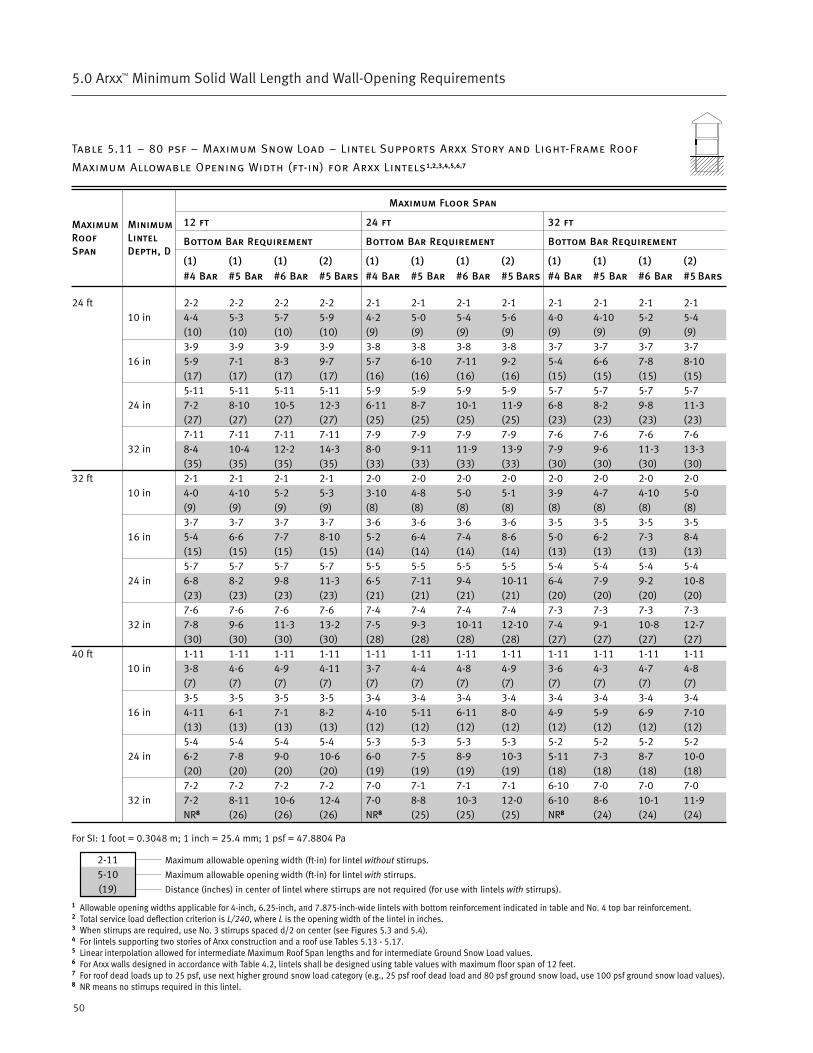
50
5.0 Arxx™ Minimum Solid Wall Length and Wall-Opening Requirements
Table 5.11 – 80 psf – Maximum Snow Load – Lintel Supports Arxx Story and Light-Frame Roof
Maximum Allowable Opening Width (ft-in) for Arxx Lintels1,2,3,4,5,6,7
Maximum Floor Span
12 ft 24 ft 32 ft
Bottom Bar Requirement Bottom Bar Requirement Bottom Bar Requirement
(1) (1) (1) (2) (1) (1) (1) (2) (1) (1) (1) (2)
#4 Bar #5 Bar #6 Bar #5 Bars #4 Bar #5 Bar #6 Bar #5 Bars #4 Bar #5 Bar #6 Bar #5 Bars
24 ft 2-2 2-2 2-2 2-2 2-1 2-1 2-1 2-1 2-1 2-1 2-1 2-110 in 4-4 5-3 5-7 5-9 4-2 5-0 5-4 5-6 4-0 4-10 5-2 5-4
(10) (10) (10) (10) (9) (9) (9) (9) (9) (9) (9) (9)3-9 3-9 3-9 3-9 3-8 3-8 3-8 3-8 3-7 3-7 3-7 3-7
16 in 5-9 7-1 8-3 9-7 5-7 6-10 7-11 9-2 5-4 6-6 7-8 8-10(17) (17) (17) (17) (16) (16) (16) (16) (15) (15) (15) (15)5-11 5-11 5-11 5-11 5-9 5-9 5-9 5-9 5-7 5-7 5-7 5-7
24 in 7-2 8-10 10-5 12-3 6-11 8-7 10-1 11-9 6-8 8-2 9-8 11-3(27) (27) (27) (27) (25) (25) (25) (25) (23) (23) (23) (23)7-11 7-11 7-11 7-11 7-9 7-9 7-9 7-9 7-6 7-6 7-6 7-6
32 in 8-4 10-4 12-2 14-3 8-0 9-11 11-9 13-9 7-9 9-6 11-3 13-3(35) (35) (35) (35) (33) (33) (33) (33) (30) (30) (30) (30)
32 ft 2-1 2-1 2-1 2-1 2-0 2-0 2-0 2-0 2-0 2-0 2-0 2-010 in 4-0 4-10 5-2 5-3 3-10 4-8 5-0 5-1 3-9 4-7 4-10 5-0
(9) (9) (9) (9) (8) (8) (8) (8) (8) (8) (8) (8)3-7 3-7 3-7 3-7 3-6 3-6 3-6 3-6 3-5 3-5 3-5 3-5
16 in 5-4 6-6 7-7 8-10 5-2 6-4 7-4 8-6 5-0 6-2 7-3 8-4(15) (15) (15) (15) (14) (14) (14) (14) (13) (13) (13) (13)5-7 5-7 5-7 5-7 5-5 5-5 5-5 5-5 5-4 5-4 5-4 5-4
24 in 6-8 8-2 9-8 11-3 6-5 7-11 9-4 10-11 6-4 7-9 9-2 10-8(23) (23) (23) (23) (21) (21) (21) (21) (20) (20) (20) (20)7-6 7-6 7-6 7-6 7-4 7-4 7-4 7-4 7-3 7-3 7-3 7-3
32 in 7-8 9-6 11-3 13-2 7-5 9-3 10-11 12-10 7-4 9-1 10-8 12-7(30) (30) (30) (30) (28) (28) (28) (28) (27) (27) (27) (27)
40 ft 1-11 1-11 1-11 1-11 1-11 1-11 1-11 1-11 1-11 1-11 1-11 1-1110 in 3-8 4-6 4-9 4-11 3-7 4-4 4-8 4-9 3-6 4-3 4-7 4-8
(7) (7) (7) (7) (7) (7) (7) (7) (7) (7) (7) (7)3-5 3-5 3-5 3-5 3-4 3-4 3-4 3-4 3-4 3-4 3-4 3-4
16 in 4-11 6-1 7-1 8-2 4-10 5-11 6-11 8-0 4-9 5-9 6-9 7-10(13) (13) (13) (13) (12) (12) (12) (12) (12) (12) (12) (12)5-4 5-4 5-4 5-4 5-3 5-3 5-3 5-3 5-2 5-2 5-2 5-2
24 in 6-2 7-8 9-0 10-6 6-0 7-5 8-9 10-3 5-11 7-3 8-7 10-0(20) (20) (20) (20) (19) (19) (19) (19) (18) (18) (18) (18)7-2 7-2 7-2 7-2 7-0 7-1 7-1 7-1 6-10 7-0 7-0 7-0
32 in 7-2 8-11 10-6 12-4 7-0 8-8 10-3 12-0 6-10 8-6 10-1 11-9NR8 (26) (26) (26) NR8 (25) (25) (25) NR8 (24) (24) (24)
For SI: 1 foot = 0.3048 m; 1 inch = 25.4 mm; 1 psf = 47.8804 Pa
1 Allowable opening widths applicable for 4-inch, 6.25-inch, and 7.875-inch-wide lintels with bottom reinforcement indicated in table and No. 4 top bar reinforcement.2 Total service load deflection criterion is L/240, where L is the opening width of the lintel in inches.3 When stirrups are required, use No. 3 stirrups spaced d/2 on center (see Figures 5.3 and 5.4).4 For lintels supporting two stories of Arxx construction and a roof use Tables 5.13 - 5.17.5 Linear interpolation allowed for intermediate Maximum Roof Span lengths and for intermediate Ground Snow Load values.6 For Arxx walls designed in accordance with Table 4.2, lintels shall be designed using table values with maximum floor span of 12 feet.7 For roof dead loads up to 25 psf, use next higher ground snow load category (e.g., 25 psf roof dead load and 80 psf ground snow load, use 100 psf ground snow load values).8 NR means no stirrups required in this lintel.
MaximumRoofSpan
MinimumLintelDepth, D
2-115-10(19)
Maximum allowable opening width (ft-in) for lintel without stirrups.
Maximum allowable opening width (ft-in) for lintel with stirrups.
Distance (inches) in center of lintel where stirrups are not required (for use with lintels with stirrups).
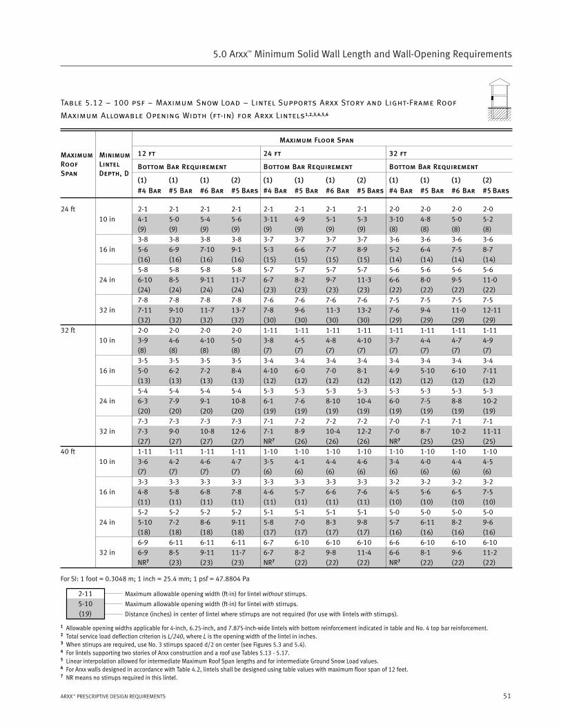
51ARXX™ PRESCRIPTIVE DESIGN REQUIREMENTS
5.0 Arxx™ Minimum Solid Wall Length and Wall-Opening Requirements
Table 5.12 – 100 psf – Maximum Snow Load – Lintel Supports Arxx Story and Light-Frame Roof
Maximum Allowable Opening Width (ft-in) for Arxx Lintels1,2,3,4,5,6
Maximum Floor Span
12 ft 24 ft 32 ft
Bottom Bar Requirement Bottom Bar Requirement Bottom Bar Requirement
(1) (1) (1) (2) (1) (1) (1) (2) (1) (1) (1) (2)
#4 Bar #5 Bar #6 Bar #5 Bars #4 Bar #5 Bar #6 Bar #5 Bars #4 Bar #5 Bar #6 Bar #5 Bars
24 ft 2-1 2-1 2-1 2-1 2-1 2-1 2-1 2-1 2-0 2-0 2-0 2-010 in 4-1 5-0 5-4 5-6 3-11 4-9 5-1 5-3 3-10 4-8 5-0 5-2
(9) (9) (9) (9) (9) (9) (9) (9) (8) (8) (8) (8)3-8 3-8 3-8 3-8 3-7 3-7 3-7 3-7 3-6 3-6 3-6 3-6
16 in 5-6 6-9 7-10 9-1 5-3 6-6 7-7 8-9 5-2 6-4 7-5 8-7(16) (16) (16) (16) (15) (15) (15) (15) (14) (14) (14) (14)5-8 5-8 5-8 5-8 5-7 5-7 5-7 5-7 5-6 5-6 5-6 5-6
24 in 6-10 8-5 9-11 11-7 6-7 8-2 9-7 11-3 6-6 8-0 9-5 11-0(24) (24) (24) (24) (23) (23) (23) (23) (22) (22) (22) (22)7-8 7-8 7-8 7-8 7-6 7-6 7-6 7-6 7-5 7-5 7-5 7-5
32 in 7-11 9-10 11-7 13-7 7-8 9-6 11-3 13-2 7-6 9-4 11-0 12-11(32) (32) (32) (32) (30) (30) (30) (30) (29) (29) (29) (29)
32 ft 2-0 2-0 2-0 2-0 1-11 1-11 1-11 1-11 1-11 1-11 1-11 1-1110 in 3-9 4-6 4-10 5-0 3-8 4-5 4-8 4-10 3-7 4-4 4-7 4-9
(8) (8) (8) (8) (7) (7) (7) (7) (7) (7) (7) (7)3-5 3-5 3-5 3-5 3-4 3-4 3-4 3-4 3-4 3-4 3-4 3-4
16 in 5-0 6-2 7-2 8-4 4-10 6-0 7-0 8-1 4-9 5-10 6-10 7-11(13) (13) (13) (13) (12) (12) (12) (12) (12) (12) (12) (12)5-4 5-4 5-4 5-4 5-3 5-3 5-3 5-3 5-3 5-3 5-3 5-3
24 in 6-3 7-9 9-1 10-8 6-1 7-6 8-10 10-4 6-0 7-5 8-8 10-2(20) (20) (20) (20) (19) (19) (19) (19) (19) (19) (19) (19)7-3 7-3 7-3 7-3 7-1 7-2 7-2 7-2 7-0 7-1 7-1 7-1
32 in 7-3 9-0 10-8 12-6 7-1 8-9 10-4 12-2 7-0 8-7 10-2 11-11(27) (27) (27) (27) NR7 (26) (26) (26) NR7 (25) (25) (25)
40 ft 1-11 1-11 1-11 1-11 1-10 1-10 1-10 1-10 1-10 1-10 1-10 1-1010 in 3-6 4-2 4-6 4-7 3-5 4-1 4-4 4-6 3-4 4-0 4-4 4-5
(7) (7) (7) (7) (6) (6) (6) (6) (6) (6) (6) (6)3-3 3-3 3-3 3-3 3-3 3-3 3-3 3-3 3-2 3-2 3-2 3-2
16 in 4-8 5-8 6-8 7-8 4-6 5-7 6-6 7-6 4-5 5-6 6-5 7-5(11) (11) (11) (11) (11) (11) (11) (11) (10) (10) (10) (10)5-2 5-2 5-2 5-2 5-1 5-1 5-1 5-1 5-0 5-0 5-0 5-0
24 in 5-10 7-2 8-6 9-11 5-8 7-0 8-3 9-8 5-7 6-11 8-2 9-6(18) (18) (18) (18) (17) (17) (17) (17) (16) (16) (16) (16)6-9 6-11 6-11 6-11 6-7 6-10 6-10 6-10 6-6 6-10 6-10 6-10
32 in 6-9 8-5 9-11 11-7 6-7 8-2 9-8 11-4 6-6 8-1 9-6 11-2NR7 (23) (23) (23) NR7 (22) (22) (22) NR7 (22) (22) (22)
For SI: 1 foot = 0.3048 m; 1 inch = 25.4 mm; 1 psf = 47.8804 Pa
1 Allowable opening widths applicable for 4-inch, 6.25-inch, and 7.875-inch-wide lintels with bottom reinforcement indicated in table and No. 4 top bar reinforcement.2 Total service load deflection criterion is L/240, where L is the opening width of the lintel in inches.3 When stirrups are required, use No. 3 stirrups spaced d/2 on center (see Figures 5.3 and 5.4).4 For lintels supporting two stories of Arxx construction and a roof use Tables 5.13 - 5.17.5 Linear interpolation allowed for intermediate Maximum Roof Span lengths and for intermediate Ground Snow Load values.6 For Arxx walls designed in accordance with Table 4.2, lintels shall be designed using table values with maximum floor span of 12 feet.7 NR means no stirrups required in this lintel.
MaximumRoofSpan
MinimumLintelDepth, D
2-115-10(19)
Maximum allowable opening width (ft-in) for lintel without stirrups.
Maximum allowable opening width (ft-in) for lintel with stirrups.
Distance (inches) in center of lintel where stirrups are not required (for use with lintels with stirrups).

52
5.0 Arxx™ Minimum Solid Wall Length and Wall-Opening Requirements
Table 5.13 – 20 psf – Maximum Snow Load – Lintel Supports Arxx First Story, Arxx Second Story
and Light-Frame Roof – Maximum Allowable Opening Width (ft-in) for Arxx Lintels1,2,3,4,5,6,7
Maximum Floor Span
12 ft 24 ft 32 ft
Bottom Bar Requirement Bottom Bar Requirement Bottom Bar Requirement
(1) (1) (1) (2) (1) (1) (1) (2) (1) (1) (1) (2)
#4 Bar #5 Bar #6 Bar #5 Bars #4 Bar #5 Bar #6 Bar #5 Bars #4 Bar #5 Bar #6 Bar #5 Bars
24 ft 2-0 2-0 2-0 2-0 1-10 1-10 1-10 1-10 1-10 1-10 1-10 1-1010 in 3-10 4-8 5-0 5-2 3-5 4-2 4-5 4-7 3-3 3-11 4-2 4-4
(8) (8) (8) (8) (6) (6) (6) (6) (6) (6) (6) (6)3-6 3-6 3-6 3-6 3-3 3-3 3-3 3-3 3-2 3-2 3-2 3-2
16 in 5-2 6-4 7-5 8-6 4-7 5-8 6-7 7-8 4-4 5-4 6-3 7-2(14) (14) (14) (14) (11) (11) (11) (11) (10) (10) (10) (10)5-5 5-5 5-5 5-5 5-1 5-1 5-1 5-1 4-11 4-11 4-11 4-11
24 in 6-5 7-11 9-4 10-11 5-9 7-2 8-5 9-10 5-5 6-9 7-11 9-3(21) (21) (21) (21) (17) (17) (17) (17) (15) (15) (15) (15)7-5 7-5 7-5 7-5 6-9 6-11 6-11 6-11 6-4 6-9 6-9 6-9
32 in 7-6 9-3 10-11 12-10 6-9 8-4 9-10 11-7 6-4 7-10 9-3 10-10(29) (29) (29) (29) NR8 (23) (23) (23) NR8 (21) (21) (21)
32 ft 2-0 2-0 2-0 2-0 1-10 1-10 1-10 1-10 1-9 1-9 1-9 1-910 in 3-9 4-6 4-10 5-0 3-4 4-1 4-4 4-6 3-2 3-10 4-1 4-3
(8) (8) (8) (8) (6) (6) (6) (6) (5) (5) (5) (5)3-5 3-5 3-5 3-5 3-3 3-3 3-3 3-3 3-1 3-1 3-1 3-1
16 in 5-0 6-1 7-2 8-3 4-6 5-6 6-5 7-6 4-3 5-2 6-1 7-0(13) (13) (13) (13) (11) (11) (11) (11) (9) (9) (9) (9)5-4 5-4 5-4 5-4 5-0 5-0 5-0 5-0 4-11 4-11 4-11 4-11
24 in 6-3 7-9 9-1 10-7 5-8 7-0 8-2 9-7 5-4 6-7 7-9 9-1(20) (20) (20) (20) (16) (16) (16) (16) (15) (15) (15) (15)7-3 7-3 7-3 7-3 6-7 6-10 6-10 6-10 6-2 6-8 6-8 6-8
32 in 7-3 9-0 10-7 12-5 6-7 8-1 9-7 11-3 6-2 7-8 9-1 10-8(27) (27) (27) (27) NR8 (22) (22) (22) NR8 (20) (20) (20)
40 ft 1-11 1-11 1-11 1-11 1-10 1-10 1-10 1-10 1-9 1-9 1-9 1-910 in 3-7 4-5 4-8 4-10 3-3 4-0 4-3 4-4 3-1 3-9 4-0 4-2
(7) (7) (7) (7) (6) (6) (6) (6) (5) (5) (5) (5)3-4 3-4 3-4 3-4 3-2 3-2 3-2 3-2 3-1 3-1 3-1 3-1
16 in 4-10 5-11 6-11 8-0 4-5 5-5 6-4 7-3 4-2 5-1 5-11 6-11(12) (12) (12) (12) (10) (10) (10) (10) (9) (9) (9) (9)5-3 5-3 5-3 5-3 5-0 5-0 5-0 5-0 4-10 4-10 4-10 4-10
24 in 6-1 7-6 8-10 10-4 5-6 6-10 8-0 9-4 5-3 6-5 7-7 8-10(19) (19) (19) (19) (16) (16) (16) (16) (14) (14) (14) (14)7-1 7-2 7-2 7-2 6-5 6-9 6-9 6-9 6-1 6-7 6-7 6-7
32 in 7-1 8-9 10-4 12-1 6-5 7-11 9-5 11-0 6-1 7-6 8-11 10-5NR8 (26) (26) (26) NR8 (21) (21) (21) NR8 (19) (19) (19)
For SI: 1 foot = 0.3048 m; 1 inch = 25.4 mm; 1 psf = 47.8804 Pa
1 Allowable opening widths applicable for 4-inch, 6.25-inch, and 7.875-inch-wide lintels with bottom reinforcement indicated in table and No. 4 top bar reinforcement.2 Total service load deflection criterion is L/240, where L is the opening width of the lintel in inches.3 When stirrups are required, use No. 3 stirrups spaced d/2 on center (see Figures 5.3 and 5.4).4 For lintels used in basements with light framed walls above, the table values may be multiplied by the following adjustment factors; 1.07 for lintels without stirrups; 1.16 for
lintels with stirrups; and 1.34 for center distance.5 Lintels in basement walls with Arxx first story and light framed second story and roof, the table values are to be used with no adjustment factors.6 Linear interpolation allowed for intermediate Maximum Roof Span lengths and for intermediate Ground Snow Load values.7 For roof dead loads up to 25 psf, use next higher ground snow load category (e.g., 25 psf roof dead load and 20 psf ground snow load, use 40 psf ground snow load values).8 NR means no stirrups required in this lintel.
MaximumRoofSpan
MinimumLintelDepth, D
2-115-10(19)
Maximum allowable opening width (ft-in) for lintel without stirrups.
Maximum allowable opening width (ft-in) for lintel with stirrups.
Distance (inches) in center of lintel where stirrups are not required (for use with lintels with stirrups).

53ARXX™ PRESCRIPTIVE DESIGN REQUIREMENTS
5.0 Arxx™ Minimum Solid Wall Length and Wall-Opening Requirements
Table 5.14 – 40 psf – Maximum Snow Load – Lintel Supports Arxx First Story, Arxx Second Story
and Light-Frame Roof – Maximum Allowable Opening Width (ft-in) for Arxx Lintels1,2,3,4,5,6,7
Maximum Floor Span
12 ft 24 ft 32 ft
Bottom Bar Requirement Bottom Bar Requirement Bottom Bar Requirement
(1) (1) (1) (2) (1) (1) (1) (2) (1) (1) (1) (2)
#4 Bar #5 Bar #6 Bar #5 Bars #4 Bar #5 Bar #6 Bar #5 Bars #4 Bar #5 Bar #6 Bar #5 Bars
24 ft 2-0 2-0 2-0 2-0 1-10 1-10 1-10 1-10 1-10 1-10 1-10 1-1010 in 3-10 4-7 4-11 5-1 3-5 4-1 4-5 4-7 3-2 3-11 4-2 4-3
(8) (8) (8) (8) (6) (6) (6) (6) (6) (6) (6) (6)3-6 3-6 3-6 3-6 3-3 3-3 3-3 3-3 3-2 3-2 3-2 3-2
16 in 5-1 6-3 7-3 8-5 4-7 5-7 6-7 7-7 4-4 5-3 6-2 7-2(14) (14) (14) (14) (11) (11) (11) (11) (10) (10) (10) (10)5-5 5-5 5-5 5-5 5-1 5-1 5-1 5-1 4-11 4-11 4-11 4-11
24 in 6-4 7-10 9-3 10-10 5-9 7-1 8-4 9-9 5-5 6-8 7-10 9-2(21) (21) (21) (21) (17) (17) (17) (17) (15) (15) (15) (15)7-4 7-4 7-4 7-4 6-8 6-11 6-11 6-11 6-3 6-8 6-8 6-8
32 in 7-5 9-2 10-10 12-8 6-8 8-3 9-9 11-5 6-3 7-9 9-2 10-9(28) (28) (28) (28) NR8 (23) (23) (23) NR8 (20) (20) (20)
32 ft 1-11 1-11 1-11 1-11 1-10 1-10 1-10 1-10 1-9 1-9 1-9 1-910 in 3-8 4-5 4-9 4-11 3-4 4-0 4-3 4-5 3-1 3-9 4-1 4-2
(7) (7) (7) (7) (6) (6) (6) (6) (5) (5) (5) (5)3-5 3-5 3-5 3-5 3-2 3-2 3-2 3-2 3-1 3-1 3-1 3-1
16 in 4-11 6-0 7-1 8-2 4-5 5-5 6-4 7-4 4-2 5-2 6-0 6-11(13) (13) (13) (13) (10) (10) (10) (10) (9) (9) (9) (9)5-4 5-4 5-4 5-4 5-0 5-0 5-0 5-0 4-10 4-10 4-10 4-10
24 in 6-2 7-7 8-11 10-5 5-7 6-10 8-1 9-6 5-3 6-6 7-8 8-11(20) (20) (20) (20) (16) (16) (16) (16) (14) (14) (14) (14)7-2 7-2 7-2 7-2 6-6 6-10 6-10 6-10 6-2 6-7 6-7 6-7
32 in 7-2 8-10 10-5 12-3 6-6 8-0 9-6 11-1 6-2 7-7 9-0 10-6(86) (26) (26) (26) NR8 (22) (22) (22) NR8 (19) (19) (19)
40 ft 1-11 1-11 1-11 1-11 1-10 1-10 1-10 1-10 1-9 1-9 1-9 1-910 in 3-7 4-4 4-7 4-9 3-3 3-11 4-2 4-4 3-1 3-8 3-11 4-1
(7) (7) (7) (7) (6) (6) (6) (6) (5) (5) (5) (5)3-4 3-4 3-4 3-4 3-2 3-2 3-2 3-2 3-1 3-1 3-1 3-1
16 in 4-9 5-10 6-10 7-11 4-4 5-4 6-2 7-2 4-1 5-0 5-10 6-9(12) (12) (12) (12) (10) (10) (10) (10) (9) (9) (9) (9)5-2 5-2 5-2 5-2 4-11 4-11 4-11 4-11 4-10 4-10 4-10 4-10
24 in 6-0 7-4 8-8 10-1 5-5 6-8 7-11 9-3 5-2 6-4 7-6 8-9(18) (18) (18) (18) (15) (15) (15) (15) (14) (14) (14) (14)6-11 7-1 7-1 7-1 6-4 6-8 6-8 6-8 6-0 6-6 6-6 6-6
32 in 6-11 8-7 10-2 11-11 6-4 7-10 9-3 10-10 6-0 7-5 8-9 10-3NR8 (25) (25) (25) NR8 (20) (20) (20) NR8 (18) (18) (18)
For SI: 1 foot = 0.3048 m; 1 inch = 25.4 mm; 1 psf = 47.8804 Pa
1 Allowable opening widths applicable for 4-inch, 6.25-inch, and 7.875-inch-wide lintels with bottom reinforcement indicated in table and No. 4 top bar reinforcement.2 Total service load deflection criterion is L/240, where L is the opening width of the lintel in inches.3 When stirrups are required, use No. 3 stirrups spaced d/2 on center (see Figures 5.3 and 5.4).4 For lintels used in basements with light framed walls above, the table values may be multiplied by the following adjustment factors; 1.07 for lintels without stirrups; 1.16 for
lintels with stirrups; and 1.34 for center distance.5 Lintels in basement walls with Arxx first story and light framed second story and roof, the table values are to be used with no adjustment factors.6 Linear interpolation allowed for intermediate Maximum Roof Span lengths and for intermediate Ground Snow Load values.7 For roof dead loads up to 25 psf, use next higher ground snow load category (e.g., 25 psf roof dead load and 40 psf ground snow load, use 60 psf ground snow load values).8 NR means no stirrups required in this lintel.
MaximumRoofSpan
MinimumLintelDepth, D
2-115-10(19)
Maximum allowable opening width (ft-in) for lintel without stirrups.
Maximum allowable opening width (ft-in) for lintel with stirrups.
Distance (inches) in center of lintel where stirrups are not required (for use with lintels with stirrups).
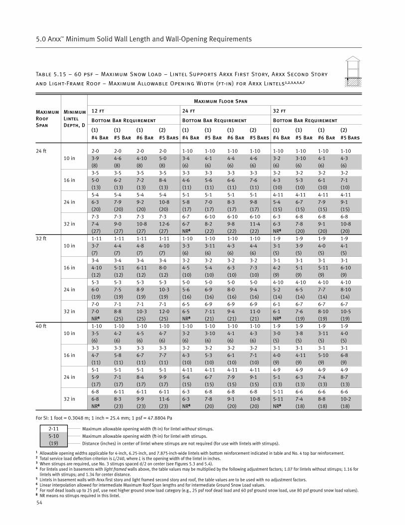
54
5.0 Arxx™ Minimum Solid Wall Length and Wall-Opening Requirements
Table 5.15 – 60 psf – Maximum Snow Load – Lintel Supports Arxx First Story, Arxx Second Story
and Light-Frame Roof – Maximum Allowable Opening Width (ft-in) for Arxx Lintels1,2,3,4,5,6,7
Maximum Floor Span
12 ft 24 ft 32 ft
Bottom Bar Requirement Bottom Bar Requirement Bottom Bar Requirement
(1) (1) (1) (2) (1) (1) (1) (2) (1) (1) (1) (2)
#4 Bar #5 Bar #6 Bar #5 Bars #4 Bar #5 Bar #6 Bar #5 Bars #4 Bar #5 Bar #6 Bar #5 Bars
24 ft 2-0 2-0 2-0 2-0 1-10 1-10 1-10 1-10 1-10 1-10 1-10 1-1010 in 3-9 4-6 4-10 5-0 3-4 4-1 4-4 4-6 3-2 3-10 4-1 4-3
(8) (8) (8) (8) (6) (6) (6) (6) (6) (6) (6) (6)3-5 3-5 3-5 3-5 3-3 3-3 3-3 3-3 3-2 3-2 3-2 3-2
16 in 5-0 6-2 7-2 8-4 4-6 5-6 6-6 7-6 4-3 5-3 6-1 7-1(13) (13) (13) (13) (11) (11) (11) (11) (10) (10) (10) (10)5-4 5-4 5-4 5-4 5-1 5-1 5-1 5-1 4-11 4-11 4-11 4-11
24 in 6-3 7-9 9-2 10-8 5-8 7-0 8-3 9-8 5-4 6-7 7-9 9-1(20) (20) (20) (20) (17) (17) (17) (17) (15) (15) (15) (15)7-3 7-3 7-3 7-3 6-7 6-10 6-10 6-10 6-3 6-8 6-8 6-8
32 in 7-4 9-0 10-8 12-6 6-7 8-2 9-8 11-4 6-3 7-8 9-1 10-8(27) (27) (27) (27) NR8 (22) (22) (22) NR8 (20) (20) (20)
32 ft 1-11 1-11 1-11 1-11 1-10 1-10 1-10 1-10 1-9 1-9 1-9 1-910 in 3-7 4-4 4-8 4-10 3-3 3-11 4-3 4-4 3-1 3-9 4-0 4-1
(7) (7) (7) (7) (6) (6) (6) (6) (5) (5) (5) (5)3-4 3-4 3-4 3-4 3-2 3-2 3-2 3-2 3-1 3-1 3-1 3-1
16 in 4-10 5-11 6-11 8-0 4-5 5-4 6-3 7-3 4-2 5-1 5-11 6-10(12) (12) (12) (12) (10) (10) (10) (10) (9) (9) (9) (9)5-3 5-3 5-3 5-3 5-0 5-0 5-0 5-0 4-10 4-10 4-10 4-10
24 in 6-0 7-5 8-9 10-3 5-6 6-9 8-0 9-4 5-2 6-5 7-7 8-10(19) (19) (19) (19) (16) (16) (16) (16) (14) (14) (14) (14)7-0 7-1 7-1 7-1 6-5 6-9 6-9 6-9 6-1 6-7 6-7 6-7
32 in 7-0 8-8 10-3 12-0 6-5 7-11 9-4 11-0 6-1 7-6 8-10 10-5NR8 (25) (25) (25) NR8 (21) (21) (21) NR8 (19) (19) (19)
40 ft 1-10 1-10 1-10 1-10 1-10 1-10 1-10 1-10 1-9 1-9 1-9 1-910 in 3-5 4-2 4-5 4-7 3-2 3-10 4-1 4-3 3-0 3-8 3-11 4-0
(6) (6) (6) (6) (6) (6) (6) (6) (5) (5) (5) (5)3-3 3-3 3-3 3-3 3-2 3-2 3-2 3-2 3-1 3-1 3-1 3-1
16 in 4-7 5-8 6-7 7-7 4-3 5-3 6-1 7-1 4-0 4-11 5-10 6-8(11) (11) (11) (11) (10) (10) (10) (10) (9) (9) (9) (9)5-1 5-1 5-1 5-1 4-11 4-11 4-11 4-11 4-9 4-9 4-9 4-9
24 in 5-9 7-1 8-4 9-9 5-4 6-7 7-9 9-1 5-1 6-3 7-4 8-7(17) (17) (17) (17) (15) (15) (15) (15) (13) (13) (13) (13)6-8 6-11 6-11 6-11 6-3 6-8 6-8 6-8 5-11 6-6 6-6 6-6
32 in 6-8 8-3 9-9 11-6 6-3 7-8 9-1 10-8 5-11 7-4 8-8 10-2NR8 (23) (23) (23) NR8 (20) (20) (20) NR8 (18) (18) (18)
For SI: 1 foot = 0.3048 m; 1 inch = 25.4 mm; 1 psf = 47.8804 Pa
1 Allowable opening widths applicable for 4-inch, 6.25-inch, and 7.875-inch-wide lintels with bottom reinforcement indicated in table and No. 4 top bar reinforcement.2 Total service load deflection criterion is L/240, where L is the opening width of the lintel in inches.3 When stirrups are required, use No. 3 stirrups spaced d/2 on center (see Figures 5.3 and 5.4).4 For lintels used in basements with light framed walls above, the table values may be multiplied by the following adjustment factors; 1.07 for lintels without stirrups; 1.16 for
lintels with stirrups; and 1.34 for center distance.5 Lintels in basement walls with Arxx first story and light framed second story and roof, the table values are to be used with no adjustment factors.6 Linear interpolation allowed for intermediate Maximum Roof Span lengths and for intermediate Ground Snow Load values.7 For roof dead loads up to 25 psf, use next higher ground snow load category (e.g., 25 psf roof dead load and 60 psf ground snow load, use 80 psf ground snow load values).8 NR means no stirrups required in this lintel.
MaximumRoofSpan
MinimumLintelDepth, D
2-115-10(19)
Maximum allowable opening width (ft-in) for lintel without stirrups.
Maximum allowable opening width (ft-in) for lintel with stirrups.
Distance (inches) in center of lintel where stirrups are not required (for use with lintels with stirrups).
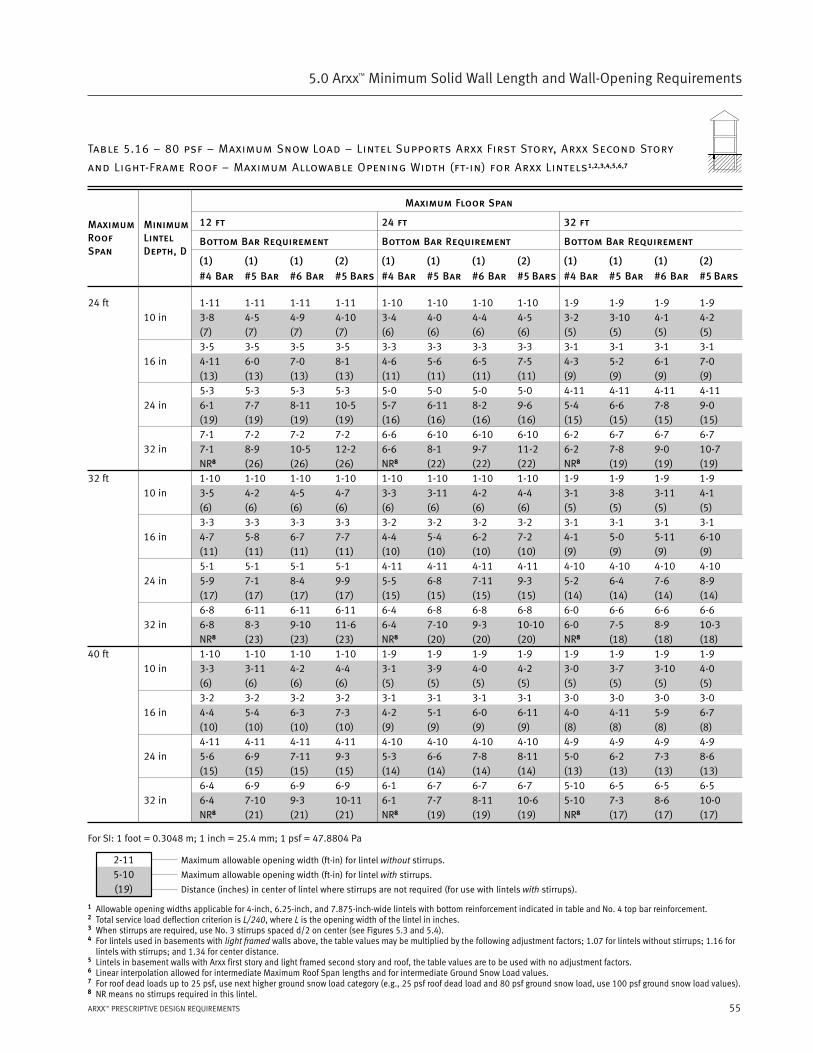
55ARXX™ PRESCRIPTIVE DESIGN REQUIREMENTS
5.0 Arxx™ Minimum Solid Wall Length and Wall-Opening Requirements
Table 5.16 – 80 psf – Maximum Snow Load – Lintel Supports Arxx First Story, Arxx Second Story
and Light-Frame Roof – Maximum Allowable Opening Width (ft-in) for Arxx Lintels1,2,3,4,5,6,7
Maximum Floor Span
12 ft 24 ft 32 ft
Bottom Bar Requirement Bottom Bar Requirement Bottom Bar Requirement
(1) (1) (1) (2) (1) (1) (1) (2) (1) (1) (1) (2)
#4 Bar #5 Bar #6 Bar #5 Bars #4 Bar #5 Bar #6 Bar #5 Bars #4 Bar #5 Bar #6 Bar #5 Bars
24 ft 1-11 1-11 1-11 1-11 1-10 1-10 1-10 1-10 1-9 1-9 1-9 1-910 in 3-8 4-5 4-9 4-10 3-4 4-0 4-4 4-5 3-2 3-10 4-1 4-2
(7) (7) (7) (7) (6) (6) (6) (6) (5) (5) (5) (5)3-5 3-5 3-5 3-5 3-3 3-3 3-3 3-3 3-1 3-1 3-1 3-1
16 in 4-11 6-0 7-0 8-1 4-6 5-6 6-5 7-5 4-3 5-2 6-1 7-0(13) (13) (13) (13) (11) (11) (11) (11) (9) (9) (9) (9)5-3 5-3 5-3 5-3 5-0 5-0 5-0 5-0 4-11 4-11 4-11 4-11
24 in 6-1 7-7 8-11 10-5 5-7 6-11 8-2 9-6 5-4 6-6 7-8 9-0(19) (19) (19) (19) (16) (16) (16) (16) (15) (15) (15) (15)7-1 7-2 7-2 7-2 6-6 6-10 6-10 6-10 6-2 6-7 6-7 6-7
32 in 7-1 8-9 10-5 12-2 6-6 8-1 9-7 11-2 6-2 7-8 9-0 10-7NR8 (26) (26) (26) NR8 (22) (22) (22) NR8 (19) (19) (19)
32 ft 1-10 1-10 1-10 1-10 1-10 1-10 1-10 1-10 1-9 1-9 1-9 1-910 in 3-5 4-2 4-5 4-7 3-3 3-11 4-2 4-4 3-1 3-8 3-11 4-1
(6) (6) (6) (6) (6) (6) (6) (6) (5) (5) (5) (5)3-3 3-3 3-3 3-3 3-2 3-2 3-2 3-2 3-1 3-1 3-1 3-1
16 in 4-7 5-8 6-7 7-7 4-4 5-4 6-2 7-2 4-1 5-0 5-11 6-10(11) (11) (11) (11) (10) (10) (10) (10) (9) (9) (9) (9)5-1 5-1 5-1 5-1 4-11 4-11 4-11 4-11 4-10 4-10 4-10 4-10
24 in 5-9 7-1 8-4 9-9 5-5 6-8 7-11 9-3 5-2 6-4 7-6 8-9(17) (17) (17) (17) (15) (15) (15) (15) (14) (14) (14) (14)6-8 6-11 6-11 6-11 6-4 6-8 6-8 6-8 6-0 6-6 6-6 6-6
32 in 6-8 8-3 9-10 11-6 6-4 7-10 9-3 10-10 6-0 7-5 8-9 10-3NR8 (23) (23) (23) NR8 (20) (20) (20) NR8 (18) (18) (18)
40 ft 1-10 1-10 1-10 1-10 1-9 1-9 1-9 1-9 1-9 1-9 1-9 1-910 in 3-3 3-11 4-2 4-4 3-1 3-9 4-0 4-2 3-0 3-7 3-10 4-0
(6) (6) (6) (6) (5) (5) (5) (5) (5) (5) (5) (5)3-2 3-2 3-2 3-2 3-1 3-1 3-1 3-1 3-0 3-0 3-0 3-0
16 in 4-4 5-4 6-3 7-3 4-2 5-1 6-0 6-11 4-0 4-11 5-9 6-7(10) (10) (10) (10) (9) (9) (9) (9) (8) (8) (8) (8)4-11 4-11 4-11 4-11 4-10 4-10 4-10 4-10 4-9 4-9 4-9 4-9
24 in 5-6 6-9 7-11 9-3 5-3 6-6 7-8 8-11 5-0 6-2 7-3 8-6(15) (15) (15) (15) (14) (14) (14) (14) (13) (13) (13) (13)6-4 6-9 6-9 6-9 6-1 6-7 6-7 6-7 5-10 6-5 6-5 6-5
32 in 6-4 7-10 9-3 10-11 6-1 7-7 8-11 10-6 5-10 7-3 8-6 10-0NR8 (21) (21) (21) NR8 (19) (19) (19) NR8 (17) (17) (17)
For SI: 1 foot = 0.3048 m; 1 inch = 25.4 mm; 1 psf = 47.8804 Pa
1 Allowable opening widths applicable for 4-inch, 6.25-inch, and 7.875-inch-wide lintels with bottom reinforcement indicated in table and No. 4 top bar reinforcement.2 Total service load deflection criterion is L/240, where L is the opening width of the lintel in inches.3 When stirrups are required, use No. 3 stirrups spaced d/2 on center (see Figures 5.3 and 5.4).4 For lintels used in basements with light framed walls above, the table values may be multiplied by the following adjustment factors; 1.07 for lintels without stirrups; 1.16 for
lintels with stirrups; and 1.34 for center distance.5 Lintels in basement walls with Arxx first story and light framed second story and roof, the table values are to be used with no adjustment factors.6 Linear interpolation allowed for intermediate Maximum Roof Span lengths and for intermediate Ground Snow Load values.7 For roof dead loads up to 25 psf, use next higher ground snow load category (e.g., 25 psf roof dead load and 80 psf ground snow load, use 100 psf ground snow load values).8 NR means no stirrups required in this lintel.
MaximumRoofSpan
MinimumLintelDepth, D
2-115-10(19)
Maximum allowable opening width (ft-in) for lintel without stirrups.
Maximum allowable opening width (ft-in) for lintel with stirrups.
Distance (inches) in center of lintel where stirrups are not required (for use with lintels with stirrups).
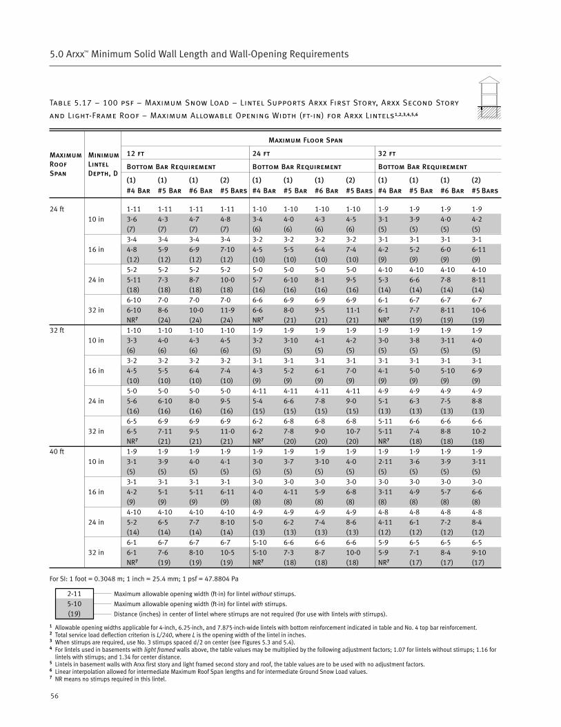
56
5.0 Arxx™ Minimum Solid Wall Length and Wall-Opening Requirements
Table 5.17 – 100 psf – Maximum Snow Load – Lintel Supports Arxx First Story, Arxx Second Story
and Light-Frame Roof – Maximum Allowable Opening Width (ft-in) for Arxx Lintels1,2,3,4,5,6
Maximum Floor Span
12 ft 24 ft 32 ft
Bottom Bar Requirement Bottom Bar Requirement Bottom Bar Requirement
(1) (1) (1) (2) (1) (1) (1) (2) (1) (1) (1) (2)
#4 Bar #5 Bar #6 Bar #5 Bars #4 Bar #5 Bar #6 Bar #5 Bars #4 Bar #5 Bar #6 Bar #5 Bars
24 ft 1-11 1-11 1-11 1-11 1-10 1-10 1-10 1-10 1-9 1-9 1-9 1-910 in 3-6 4-3 4-7 4-8 3-4 4-0 4-3 4-5 3-1 3-9 4-0 4-2
(7) (7) (7) (7) (6) (6) (6) (6) (5) (5) (5) (5)3-4 3-4 3-4 3-4 3-2 3-2 3-2 3-2 3-1 3-1 3-1 3-1
16 in 4-8 5-9 6-9 7-10 4-5 5-5 6-4 7-4 4-2 5-2 6-0 6-11(12) (12) (12) (12) (10) (10) (10) (10) (9) (9) (9) (9)5-2 5-2 5-2 5-2 5-0 5-0 5-0 5-0 4-10 4-10 4-10 4-10
24 in 5-11 7-3 8-7 10-0 5-7 6-10 8-1 9-5 5-3 6-6 7-8 8-11(18) (18) (18) (18) (16) (16) (16) (16) (14) (14) (14) (14)6-10 7-0 7-0 7-0 6-6 6-9 6-9 6-9 6-1 6-7 6-7 6-7
32 in 6-10 8-6 10-0 11-9 6-6 8-0 9-5 11-1 6-1 7-7 8-11 10-6NR7 (24) (24) (24) NR7 (21) (21) (21) NR7 (19) (19) (19)
32 ft 1-10 1-10 1-10 1-10 1-9 1-9 1-9 1-9 1-9 1-9 1-9 1-910 in 3-3 4-0 4-3 4-5 3-2 3-10 4-1 4-2 3-0 3-8 3-11 4-0
(6) (6) (6) (6) (5) (5) (5) (5) (5) (5) (5) (5)3-2 3-2 3-2 3-2 3-1 3-1 3-1 3-1 3-1 3-1 3-1 3-1
16 in 4-5 5-5 6-4 7-4 4-3 5-2 6-1 7-0 4-1 5-0 5-10 6-9(10) (10) (10) (10) (9) (9) (9) (9) (9) (9) (9) (9)5-0 5-0 5-0 5-0 4-11 4-11 4-11 4-11 4-9 4-9 4-9 4-9
24 in 5-6 6-10 8-0 9-5 5-4 6-6 7-8 9-0 5-1 6-3 7-5 8-8(16) (16) (16) (16) (15) (15) (15) (15) (13) (13) (13) (13)6-5 6-9 6-9 6-9 6-2 6-8 6-8 6-8 5-11 6-6 6-6 6-6
32 in 6-5 7-11 9-5 11-0 6-2 7-8 9-0 10-7 5-11 7-4 8-8 10-2NR7 (21) (21) (21) NR7 (20) (20) (20) NR7 (18) (18) (18)
40 ft 1-9 1-9 1-9 1-9 1-9 1-9 1-9 1-9 1-9 1-9 1-9 1-910 in 3-1 3-9 4-0 4-1 3-0 3-7 3-10 4-0 2-11 3-6 3-9 3-11
(5) (5) (5) (5) (5) (5) (5) (5) (5) (5) (5) (5)3-1 3-1 3-1 3-1 3-0 3-0 3-0 3-0 3-0 3-0 3-0 3-0
16 in 4-2 5-1 5-11 6-11 4-0 4-11 5-9 6-8 3-11 4-9 5-7 6-6(9) (9) (9) (9) (8) (8) (8) (8) (8) (8) (8) (8)4-10 4-10 4-10 4-10 4-9 4-9 4-9 4-9 4-8 4-8 4-8 4-8
24 in 5-2 6-5 7-7 8-10 5-0 6-2 7-4 8-6 4-11 6-1 7-2 8-4(14) (14) (14) (14) (13) (13) (13) (13) (12) (12) (12) (12)6-1 6-7 6-7 6-7 5-10 6-6 6-6 6-6 5-9 6-5 6-5 6-5
32 in 6-1 7-6 8-10 10-5 5-10 7-3 8-7 10-0 5-9 7-1 8-4 9-10NR7 (19) (19) (19) NR7 (18) (18) (18) NR7 (17) (17) (17)
For SI: 1 foot = 0.3048 m; 1 inch = 25.4 mm; 1 psf = 47.8804 Pa
1 Allowable opening widths applicable for 4-inch, 6.25-inch, and 7.875-inch-wide lintels with bottom reinforcement indicated in table and No. 4 top bar reinforcement.2 Total service load deflection criterion is L/240, where L is the opening width of the lintel in inches.3 When stirrups are required, use No. 3 stirrups spaced d/2 on center (see Figures 5.3 and 5.4).4 For lintels used in basements with light framed walls above, the table values may be multiplied by the following adjustment factors; 1.07 for lintels without stirrups; 1.16 for
lintels with stirrups; and 1.34 for center distance.5 Lintels in basement walls with Arxx first story and light framed second story and roof, the table values are to be used with no adjustment factors.6 Linear interpolation allowed for intermediate Maximum Roof Span lengths and for intermediate Ground Snow Load values.7 NR means no stirrups required in this lintel.
MaximumRoofSpan
MinimumLintelDepth, D
2-115-10(19)
Maximum allowable opening width (ft-in) for lintel without stirrups.
Maximum allowable opening width (ft-in) for lintel with stirrups.
Distance (inches) in center of lintel where stirrups are not required (for use with lintels with stirrups).
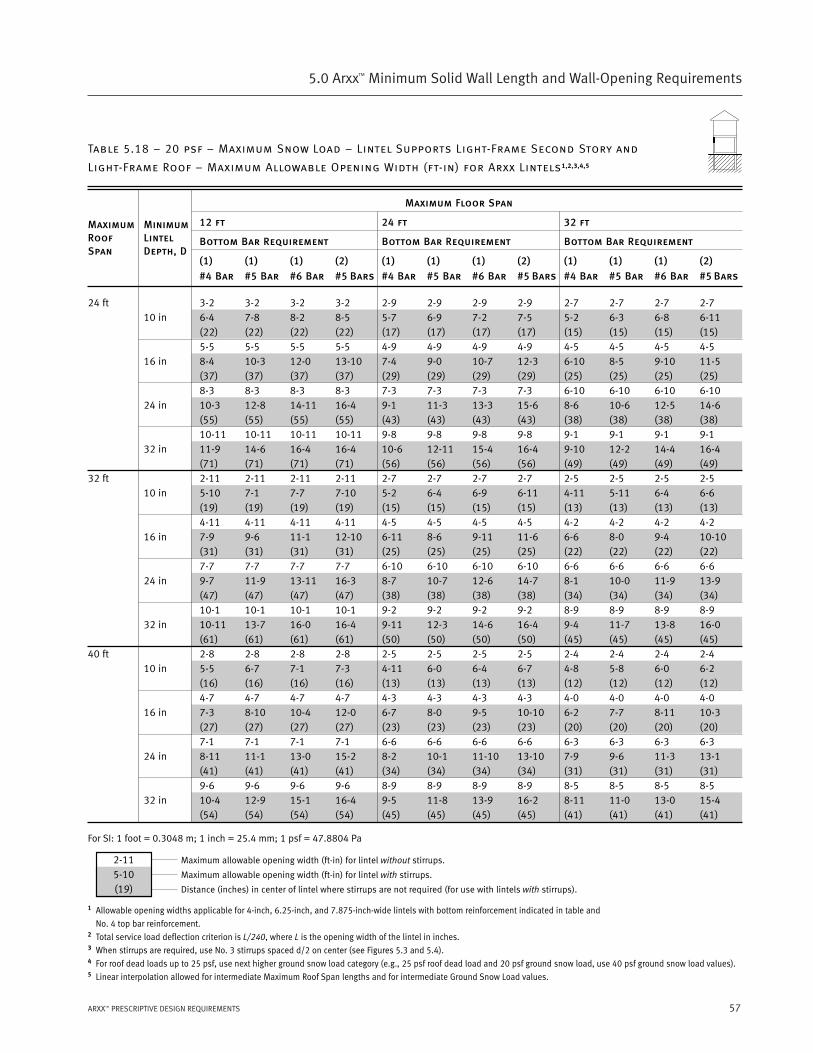
57ARXX™ PRESCRIPTIVE DESIGN REQUIREMENTS
5.0 Arxx™ Minimum Solid Wall Length and Wall-Opening Requirements
Table 5.18 – 20 psf – Maximum Snow Load – Lintel Supports Light-Frame Second Story and
Light-Frame Roof – Maximum Allowable Opening Width (ft-in) for Arxx Lintels1,2,3,4,5
Maximum Floor Span
12 ft 24 ft 32 ft
Bottom Bar Requirement Bottom Bar Requirement Bottom Bar Requirement
(1) (1) (1) (2) (1) (1) (1) (2) (1) (1) (1) (2)
#4 Bar #5 Bar #6 Bar #5 Bars #4 Bar #5 Bar #6 Bar #5 Bars #4 Bar #5 Bar #6 Bar #5 Bars
24 ft 3-2 3-2 3-2 3-2 2-9 2-9 2-9 2-9 2-7 2-7 2-7 2-710 in 6-4 7-8 8-2 8-5 5-7 6-9 7-2 7-5 5-2 6-3 6-8 6-11
(22) (22) (22) (22) (17) (17) (17) (17) (15) (15) (15) (15)5-5 5-5 5-5 5-5 4-9 4-9 4-9 4-9 4-5 4-5 4-5 4-5
16 in 8-4 10-3 12-0 13-10 7-4 9-0 10-7 12-3 6-10 8-5 9-10 11-5(37) (37) (37) (37) (29) (29) (29) (29) (25) (25) (25) (25)8-3 8-3 8-3 8-3 7-3 7-3 7-3 7-3 6-10 6-10 6-10 6-10
24 in 10-3 12-8 14-11 16-4 9-1 11-3 13-3 15-6 8-6 10-6 12-5 14-6(55) (55) (55) (55) (43) (43) (43) (43) (38) (38) (38) (38)10-11 10-11 10-11 10-11 9-8 9-8 9-8 9-8 9-1 9-1 9-1 9-1
32 in 11-9 14-6 16-4 16-4 10-6 12-11 15-4 16-4 9-10 12-2 14-4 16-4(71) (71) (71) (71) (56) (56) (56) (56) (49) (49) (49) (49)
32 ft 2-11 2-11 2-11 2-11 2-7 2-7 2-7 2-7 2-5 2-5 2-5 2-510 in 5-10 7-1 7-7 7-10 5-2 6-4 6-9 6-11 4-11 5-11 6-4 6-6
(19) (19) (19) (19) (15) (15) (15) (15) (13) (13) (13) (13)4-11 4-11 4-11 4-11 4-5 4-5 4-5 4-5 4-2 4-2 4-2 4-2
16 in 7-9 9-6 11-1 12-10 6-11 8-6 9-11 11-6 6-6 8-0 9-4 10-10(31) (31) (31) (31) (25) (25) (25) (25) (22) (22) (22) (22)7-7 7-7 7-7 7-7 6-10 6-10 6-10 6-10 6-6 6-6 6-6 6-6
24 in 9-7 11-9 13-11 16-3 8-7 10-7 12-6 14-7 8-1 10-0 11-9 13-9(47) (47) (47) (47) (38) (38) (38) (38) (34) (34) (34) (34)10-1 10-1 10-1 10-1 9-2 9-2 9-2 9-2 8-9 8-9 8-9 8-9
32 in 10-11 13-7 16-0 16-4 9-11 12-3 14-6 16-4 9-4 11-7 13-8 16-0(61) (61) (61) (61) (50) (50) (50) (50) (45) (45) (45) (45)
40 ft 2-8 2-8 2-8 2-8 2-5 2-5 2-5 2-5 2-4 2-4 2-4 2-410 in 5-5 6-7 7-1 7-3 4-11 6-0 6-4 6-7 4-8 5-8 6-0 6-2
(16) (16) (16) (16) (13) (13) (13) (13) (12) (12) (12) (12)4-7 4-7 4-7 4-7 4-3 4-3 4-3 4-3 4-0 4-0 4-0 4-0
16 in 7-3 8-10 10-4 12-0 6-7 8-0 9-5 10-10 6-2 7-7 8-11 10-3(27) (27) (27) (27) (23) (23) (23) (23) (20) (20) (20) (20)7-1 7-1 7-1 7-1 6-6 6-6 6-6 6-6 6-3 6-3 6-3 6-3
24 in 8-11 11-1 13-0 15-2 8-2 10-1 11-10 13-10 7-9 9-6 11-3 13-1(41) (41) (41) (41) (34) (34) (34) (34) (31) (31) (31) (31)9-6 9-6 9-6 9-6 8-9 8-9 8-9 8-9 8-5 8-5 8-5 8-5
32 in 10-4 12-9 15-1 16-4 9-5 11-8 13-9 16-2 8-11 11-0 13-0 15-4(54) (54) (54) (54) (45) (45) (45) (45) (41) (41) (41) (41)
For SI: 1 foot = 0.3048 m; 1 inch = 25.4 mm; 1 psf = 47.8804 Pa
1 Allowable opening widths applicable for 4-inch, 6.25-inch, and 7.875-inch-wide lintels with bottom reinforcement indicated in table and
No. 4 top bar reinforcement.2 Total service load deflection criterion is L/240, where L is the opening width of the lintel in inches.3 When stirrups are required, use No. 3 stirrups spaced d/2 on center (see Figures 5.3 and 5.4).4 For roof dead loads up to 25 psf, use next higher ground snow load category (e.g., 25 psf roof dead load and 20 psf ground snow load, use 40 psf ground snow load values).5 Linear interpolation allowed for intermediate Maximum Roof Span lengths and for intermediate Ground Snow Load values.
MaximumRoofSpan
MinimumLintelDepth, D
2-115-10(19)
Maximum allowable opening width (ft-in) for lintel without stirrups.
Maximum allowable opening width (ft-in) for lintel with stirrups.
Distance (inches) in center of lintel where stirrups are not required (for use with lintels with stirrups).

58
5.0 Arxx™ Minimum Solid Wall Length and Wall-Opening Requirements
Table 5.19 – 40 psf – Maximum Snow Load – Lintel Supports Light-Frame Second Story and
Light-Frame Roof – Maximum Allowable Opening Width (ft-in) for Arxx Lintels1,2,3,4,5
Maximum Floor Span
12 ft 24 ft 32 ft
Bottom Bar Requirement Bottom Bar Requirement Bottom Bar Requirement
(1) (1) (1) (2) (1) (1) (1) (2) (1) (1) (1) (2)
#4 Bar #5 Bar #6 Bar #5 Bars #4 Bar #5 Bar #6 Bar #5 Bars #4 Bar #5 Bar #6 Bar #5 Bars
24 ft 3-0 3-0 3-0 3-0 2-8 2-8 2-8 2-8 2-6 2-6 2-6 2-610 in 6-1 7-5 7-11 8-2 5-5 6-6 7-0 7-3 5-0 6-1 6-6 6-9
(20) (20) (20) (20) (16) (16) (16) (16) (14) (14) (14) (14)5-2 5-2 5-2 5-2 4-7 4-7 4-7 4-7 4-4 4-4 4-4 4-4
16 in 8-1 9-11 11-7 13-5 7-2 8-10 10-3 11-11 6-9 8-3 9-8 11-2(34) (34) (34) (34) (27) (27) (27) (27) (24) (24) (24) (24)7-11 7-11 7-11 7-11 7-1 7-1 7-1 7-1 6-8 6-8 6-8 6-8
24 in 10-0 12-3 14-6 16-4 8-11 11-0 12-11 15-1 8-4 10-3 12-1 14-2(51) (51) (51) (51) (41) (41) (41) (41) (36) (36) (36) (36)10-7 10-7 10-7 10-7 9-5 9-5 9-5 9-5 8-11 8-11 8-11 8-11
32 in 11-5 14-1 16-4 16-4 10-3 12-8 14-11 16-4 9-7 11-11 14-1 16-4(67) (67) (67) (67) (53) (53) (53) (53) (47) (47) (47) (47)
32 ft 2-9 2-9 2-9 2-9 2-6 2-6 2-6 2-6 2-4 2-4 2-4 2-410 in 5-7 6-9 7-3 7-6 5-0 6-1 6-6 6-9 4-9 5-9 6-2 6-4
(17) (17) (17) (17) (14) (14) (14) (14) (12) (12) (12) (12)4-9 4-9 4-9 4-9 4-4 4-4 4-4 4-4 4-1 4-1 4-1 4-1
16 in 7-5 9-1 10-8 12-4 6-9 8-3 9-8 11-2 6-4 7-9 9-1 10-6(29) (29) (29) (29) (24) (24) (24) (24) (21) (21) (21) (21)7-3 7-3 7-3 7-3 6-8 6-8 6-8 6-8 6-4 6-4 6-4 6-4
24 in 9-2 11-4 13-4 15-7 8-4 10-3 12-1 14-2 7-11 9-9 11-5 13-5(43) (43) (43) (43) (36) (36) (36) (36) (32) (32) (32) (32)9-9 9-9 9-9 9-9 8-11 8-11 8-11 8-11 8-6 8-6 8-6 8-6
32 in 10-6 13-0 15-5 16-4 9-7 11-11 14-1 16-4 9-1 11-3 13-4 15-7(57) (57) (57) (57) (47) (47) (47) (47) (42) (42) (42) (42)
40 ft 2-6 2-6 2-6 2-6 2-4 2-4 2-4 2-4 2-3 2-3 2-3 2-310 in 5-1 6-2 6-8 6-10 4-9 5-9 6-2 6-4 4-6 5-5 5-10 6-0
(14) (14) (14) (14) (12) (12) (12) (12) (11) (11) (11) (11)4-4 4-4 4-4 4-4 4-1 4-1 4-1 4-1 3-11 3-11 3-11 3-11
16 in 6-10 8-4 9-9 11-4 6-4 7-9 9-1 10-6 6-0 7-4 8-7 10-0(24) (24) (24) (24) (21) (21) (21) (21) (19) (19) (19) (19)6-9 6-9 6-9 6-9 6-4 6-4 6-4 6-4 6-1 6-1 6-1 6-1
24 in 8-6 10-5 12-4 14-5 7-11 9-9 11-5 13-5 7-6 9-3 10-11 12-9(37) (37) (37) (37) (32) (32) (32) (32) (29) (29) (29) (29)9-1 9-1 9-1 9-1 8-6 8-6 8-6 8-6 8-2 8-2 8-2 8-2
32 in 9-9 12-1 14-3 16-4 9-1 11-3 13-4 15-7 8-8 10-9 12-8 14-10(49) (49) (49) (49) (42) (42) (42) (42) (38) (38) (38) (38)
For SI: 1 foot = 0.3048 m; 1 inch = 25.4 mm; 1 psf = 47.8804 Pa
1 Allowable opening widths applicable for 4-inch, 6.25-inch, and 7.875-inch-wide lintels with bottom reinforcement indicated in table and
No. 4 top bar reinforcement.2 Total service load deflection criterion is L/240, where L is the opening width of the lintel in inches.3 When stirrups are required, use No. 3 stirrups spaced d/2 on center (see Figures 5.3 and 5.4).4 For roof dead loads up to 25 psf, use next higher ground snow load category (e.g., 25 psf roof dead load and 40 psf ground snow load, use 60 psf ground snow load values).5 Linear interpolation allowed for intermediate Maximum Roof Span lengths and for intermediate Ground Snow Load values.
MaximumRoofSpan
MinimumLintelDepth, D
2-115-10(19)
Maximum allowable opening width (ft-in) for lintel without stirrups.
Maximum allowable opening width (ft-in) for lintel with stirrups.
Distance (inches) in center of lintel where stirrups are not required (for use with lintels with stirrups).

59ARXX™ PRESCRIPTIVE DESIGN REQUIREMENTS
5.0 Arxx™ Minimum Solid Wall Length and Wall-Opening Requirements
Table 5.20 – 60 psf – Maximum Snow Load – Lintel Supports Light-Frame Second Story and
Light-Frame Roof – Maximum Allowable Opening Width (ft-in) for Arxx Lintels1,2,3,4,5
Maximum Floor Span
12 ft 24 ft 32 ft
Bottom Bar Requirement Bottom Bar Requirement Bottom Bar Requirement
(1) (1) (1) (2) (1) (1) (1) (2) (1) (1) (1) (2)
#4 Bar #5 Bar #6 Bar #5 Bars #4 Bar #5 Bar #6 Bar #5 Bars #4 Bar #5 Bar #6 Bar #5 Bars
24 ft 2-9 2-9 2-9 2-9 2-7 2-7 2-7 2-7 2-5 2-5 2-5 2-510 in 5-7 6-9 7-3 7-6 5-3 6-4 6-10 7-0 4-11 6-0 6-5 6-7
(17) (17) (17) (17) (15) (15) (15) (15) (13) (13) (13) (13)4-9 4-9 4-9 4-9 4-6 4-6 4-6 4-6 4-3 4-3 4-3 4-3
16 in 7-5 9-1 10-8 12-4 7-0 8-7 10-0 11-7 6-7 8-1 9-5 10-11(29) (29) (29) (29) (26) (26) (26) (26) (23) (23) (23) (23)7-4 7-4 7-4 7-4 6-11 6-11 6-11 6-11 6-6 6-6 6-6 6-6
24 in 9-2 11-4 13-4 15-7 8-8 10-8 12-7 14-9 8-2 10-1 11-10 13-10(44) (44) (44) (44) (39) (39) (39) (39) (34) (34) (34) (34)9-9 9-9 9-9 9-9 9-3 9-3 9-3 9-3 8-9 8-9 8-9 8-9
32 in 10-7 13-1 15-5 16-4 10-0 12-4 14-7 16-4 9-5 11-8 13-9 16-2(57) (57) (57) (57) (51) (51) (51) (51) (45) (45) (45) (45)
32 ft 2-6 2-6 2-6 2-6 2-5 2-5 2-5 2-5 2-4 2-4 2-4 2-410 in 5-0 6-1 6-6 6-8 4-9 5-10 6-2 6-5 4-7 5-7 6-0 6-2
(14) (14) (14) (14) (13) (13) (13) (13) (12) (12) (12) (12)4-3 4-3 4-3 4-3 4-1 4-1 4-1 4-1 4-0 4-0 4-0 4-0
16 in 6-8 8-2 9-7 11-1 6-5 7-10 9-2 10-7 6-2 7-7 8-10 10-3(23) (23) (23) (23) (21) (21) (21) (21) (20) (20) (20) (20)6-7 6-7 6-7 6-7 6-5 6-5 6-5 6-5 6-3 6-3 6-3 6-3
24 in 8-3 10-3 12-1 14-1 7-11 9-10 11-7 13-6 7-8 9-6 11-2 13-1(35) (35) (35) (35) (33) (33) (33) (33) (31) (31) (31) (31)8-11 8-11 8-11 8-11 8-7 8-7 8-7 8-7 8-4 8-4 8-4 8-4
32 in 9-7 11-10 14-0 16-4 9-2 11-4 13-5 15-9 8-11 11-0 13-0 15-3(47) (47) (47) (47) (43) (43) (43) (43) (40) (40) (40) (40)
40 ft 2-3 2-3 2-3 2-3 2-3 2-3 2-3 2-3 2-2 2-2 2-2 2-210 in 4-7 5-6 5-11 6-1 4-5 5-4 5-8 5-11 4-4 5-2 5-7 5-9
(11) (11) (11) (11) (11) (11) (11) (11) (10) (10) (10) (10)4-0 4-0 4-0 4-0 3-10 3-10 3-10 3-10 3-9 3-9 3-9 3-9
16 in 6-1 7-6 8-9 10-2 5-11 7-3 8-5 9-9 5-9 7-1 8-3 9-6(20) (20) (20) (20) (18) (18) (18) (18) (17) (17) (17) (17)6-2 6-2 6-2 6-2 6-0 6-0 6-0 6-0 5-11 5-11 5-11 5-11
24 in 7-7 9-5 11-1 12-11 7-4 9-1 10-8 12-6 7-2 8-10 10-5 12-2(30) (30) (30) (30) (28) (28) (28) (28) (27) (27) (27) (27)8-4 8-4 8-4 8-4 8-1 8-1 8-1 8-1 7-11 7-11 7-11 7-11
32 in 8-9 10-10 12-10 15-1 8-6 10-6 12-5 14-7 8-4 10-3 12-2 14-3(40) (40) (40) (40) (37) (37) (37) (37) (35) (35) (35) (35)
For SI: 1 foot = 0.3048 m; 1 inch = 25.4 mm; 1 psf = 47.8804 Pa
1 Allowable opening widths applicable for 4-inch, 6.25-inch, and 7.875-inch-wide lintels with bottom reinforcement indicated in table and
No. 4 top bar reinforcement.2 Total service load deflection criterion is L/240, where L is the opening width of the lintel in inches.3 When stirrups are required, use No. 3 stirrups spaced d/2 on center (see Figures 5.3 and 5.4).4 For roof dead loads up to 25 psf, use next higher ground snow load category (e.g., 25 psf roof dead load and 60 psf ground snow load, use 80 psf ground snow load values).5 Linear interpolation allowed for intermediate Maximum Roof Span lengths and for intermediate Ground Snow Load values.
MaximumRoofSpan
MinimumLintelDepth, D
2-115-10(19)
Maximum allowable opening width (ft-in) for lintel without stirrups.
Maximum allowable opening width (ft-in) for lintel with stirrups.
Distance (inches) in center of lintel where stirrups are not required (for use with lintels with stirrups).
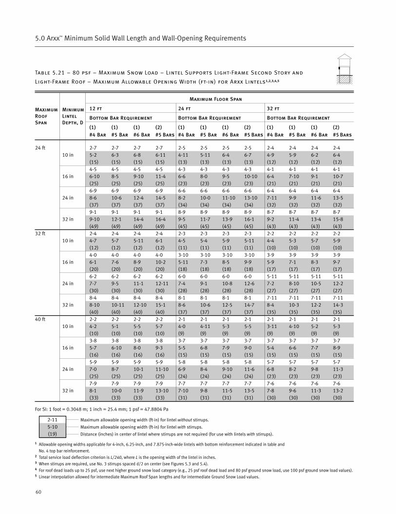
60
5.0 Arxx™ Minimum Solid Wall Length and Wall-Opening Requirements
Table 5.21 – 80 psf – Maximum Snow Load – Lintel Supports Light-Frame Second Story and
Light-Frame Roof – Maximum Allowable Opening Width (ft-in) for Arxx Lintels1,2,3,4,5
Maximum Floor Span
12 ft 24 ft 32 ft
Bottom Bar Requirement Bottom Bar Requirement Bottom Bar Requirement
(1) (1) (1) (2) (1) (1) (1) (2) (1) (1) (1) (2)
#4 Bar #5 Bar #6 Bar #5 Bars #4 Bar #5 Bar #6 Bar #5 Bars #4 Bar #5 Bar #6 Bar #5 Bars
24 ft 2-7 2-7 2-7 2-7 2-5 2-5 2-5 2-5 2-4 2-4 2-4 2-410 in 5-2 6-3 6-8 6-11 4-11 5-11 6-4 6-7 4-9 5-9 6-2 6-4
(15) (15) (15) (15) (13) (13) (13) (13) (12) (12) (12) (12)4-5 4-5 4-5 4-5 4-3 4-3 4-3 4-3 4-1 4-1 4-1 4-1
16 in 6-10 8-5 9-10 11-4 6-6 8-0 9-5 10-10 6-4 7-10 9-1 10-7(25) (25) (25) (25) (23) (23) (23) (23) (21) (21) (21) (21)6-9 6-9 6-9 6-9 6-6 6-6 6-6 6-6 6-4 6-4 6-4 6-4
24 in 8-6 10-6 12-4 14-5 8-2 10-0 11-10 13-10 7-11 9-9 11-6 13-5(37) (37) (37) (37) (34) (34) (34) (34) (32) (32) (32) (32)9-1 9-1 9-1 9-1 8-9 8-9 8-9 8-9 8-7 8-7 8-7 8-7
32 in 9-10 12-1 14-4 16-4 9-5 11-7 13-9 16-1 9-2 11-4 13-4 15-8(49) (49) (49) (49) (45) (45) (45) (45) (43) (43) (43) (43)
32 ft 2-4 2-4 2-4 2-4 2-3 2-3 2-3 2-3 2-2 2-2 2-2 2-210 in 4-7 5-7 5-11 6-1 4-5 5-4 5-9 5-11 4-4 5-3 5-7 5-9
(12) (12) (12) (12) (11) (11) (11) (11) (10) (10) (10) (10)4-0 4-0 4-0 4-0 3-10 3-10 3-10 3-10 3-9 3-9 3-9 3-9
16 in 6-1 7-6 8-9 10-2 5-11 7-3 8-5 9-9 5-9 7-1 8-3 9-7(20) (20) (20) (20) (18) (18) (18) (18) (17) (17) (17) (17)6-2 6-2 6-2 6-2 6-0 6-0 6-0 6-0 5-11 5-11 5-11 5-11
24 in 7-7 9-5 11-1 12-11 7-4 9-1 10-8 12-6 7-2 8-10 10-5 12-2(30) (30) (30) (30) (28) (28) (28) (28) (27) (27) (27) (27)8-4 8-4 8-4 8-4 8-1 8-1 8-1 8-1 7-11 7-11 7-11 7-11
32 in 8-10 10-11 12-10 15-1 8-6 10-6 12-5 14-7 8-4 10-3 12-2 14-3(40) (40) (40) (40) (37) (37) (37) (37) (35) (35) (35) (35)
40 ft 2-2 2-2 2-2 2-2 2-1 2-1 2-1 2-1 2-1 2-1 2-1 2-110 in 4-2 5-1 5-5 5-7 4-0 4-11 5-3 5-5 3-11 4-10 5-2 5-3
(10) (10) (10) (10) (9) (9) (9) (9) (9) (9) (9) (9)3-8 3-8 3-8 3-8 3-7 3-7 3-7 3-7 3-7 3-7 3-7 3-7
16 in 5-7 6-10 8-0 9-3 5-5 6-8 7-9 9-0 5-4 6-6 7-7 8-9(16) (16) (16) (16) (15) (15) (15) (15) (15) (15) (15) (15)5-9 5-9 5-9 5-9 5-8 5-8 5-8 5-8 5-7 5-7 5-7 5-7
24 in 7-0 8-7 10-1 11-10 6-9 8-4 9-10 11-6 6-8 8-2 9-8 11-3(25) (25) (25) (25) (24) (24) (24) (24) (23) (23) (23) (23)7-9 7-9 7-9 7-9 7-7 7-7 7-7 7-7 7-6 7-6 7-6 7-6
32 in 8-1 10-0 11-9 13-10 7-10 9-8 11-5 13-5 7-8 9-6 11-3 13-2(33) (33) (33) (33) (31) (31) (31) (31) (30) (30) (30) (30)
For SI: 1 foot = 0.3048 m; 1 inch = 25.4 mm; 1 psf = 47.8804 Pa
1 Allowable opening widths applicable for 4-inch, 6.25-inch, and 7.875-inch-wide lintels with bottom reinforcement indicated in table and
No. 4 top bar reinforcement.2 Total service load deflection criterion is L/240, where L is the opening width of the lintel in inches.3 When stirrups are required, use No. 3 stirrups spaced d/2 on center (see Figures 5.3 and 5.4).4 For roof dead loads up to 25 psf, use next higher ground snow load category (e.g., 25 psf roof dead load and 80 psf ground snow load, use 100 psf ground snow load values).5 Linear interpolation allowed for intermediate Maximum Roof Span lengths and for intermediate Ground Snow Load values.
MaximumRoofSpan
MinimumLintelDepth, D
2-115-10(19)
Maximum allowable opening width (ft-in) for lintel without stirrups.
Maximum allowable opening width (ft-in) for lintel with stirrups.
Distance (inches) in center of lintel where stirrups are not required (for use with lintels with stirrups).
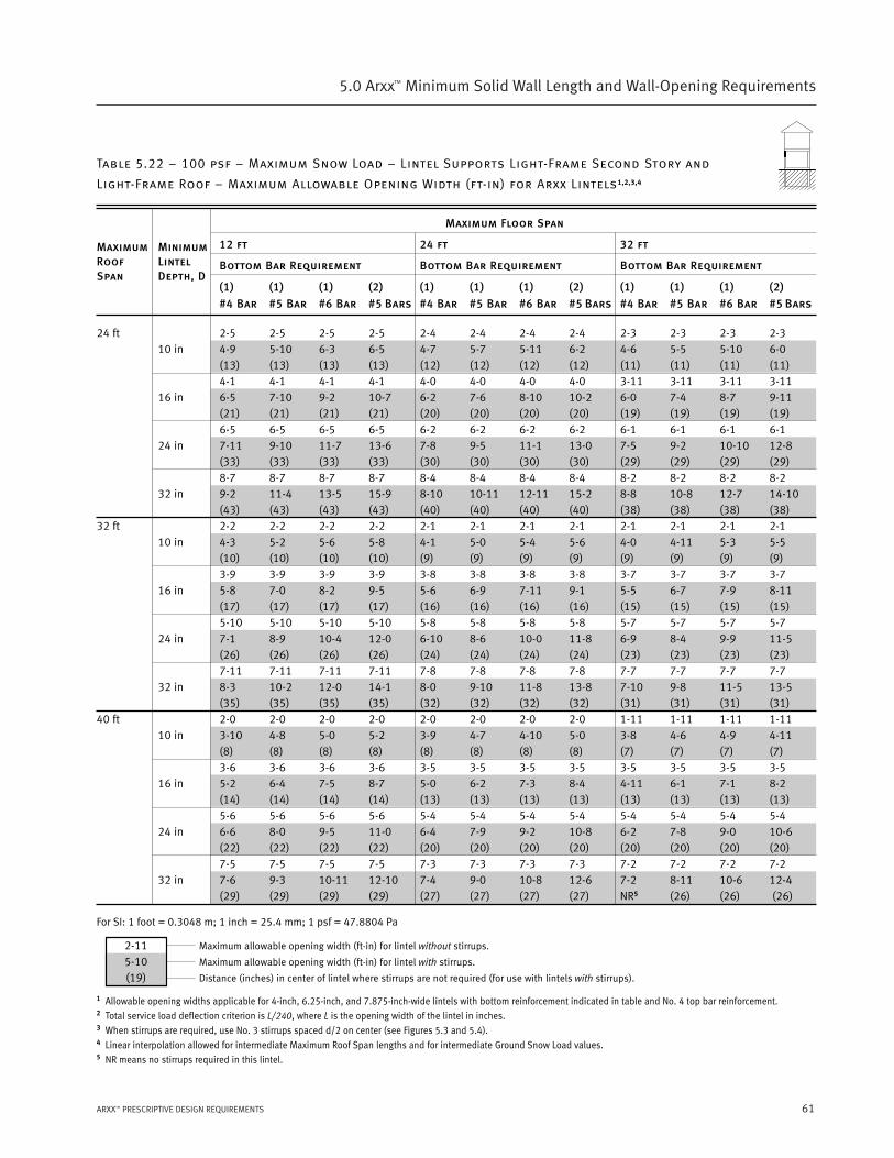
61ARXX™ PRESCRIPTIVE DESIGN REQUIREMENTS
5.0 Arxx™ Minimum Solid Wall Length and Wall-Opening Requirements
Table 5.22 – 100 psf – Maximum Snow Load – Lintel Supports Light-Frame Second Story and
Light-Frame Roof – Maximum Allowable Opening Width (ft-in) for Arxx Lintels1,2,3,4
Maximum Floor Span
12 ft 24 ft 32 ft
Bottom Bar Requirement Bottom Bar Requirement Bottom Bar Requirement
(1) (1) (1) (2) (1) (1) (1) (2) (1) (1) (1) (2)
#4 Bar #5 Bar #6 Bar #5 Bars #4 Bar #5 Bar #6 Bar #5 Bars #4 Bar #5 Bar #6 Bar #5 Bars
24 ft 2-5 2-5 2-5 2-5 2-4 2-4 2-4 2-4 2-3 2-3 2-3 2-310 in 4-9 5-10 6-3 6-5 4-7 5-7 5-11 6-2 4-6 5-5 5-10 6-0
(13) (13) (13) (13) (12) (12) (12) (12) (11) (11) (11) (11)4-1 4-1 4-1 4-1 4-0 4-0 4-0 4-0 3-11 3-11 3-11 3-11
16 in 6-5 7-10 9-2 10-7 6-2 7-6 8-10 10-2 6-0 7-4 8-7 9-11(21) (21) (21) (21) (20) (20) (20) (20) (19) (19) (19) (19)6-5 6-5 6-5 6-5 6-2 6-2 6-2 6-2 6-1 6-1 6-1 6-1
24 in 7-11 9-10 11-7 13-6 7-8 9-5 11-1 13-0 7-5 9-2 10-10 12-8(33) (33) (33) (33) (30) (30) (30) (30) (29) (29) (29) (29)8-7 8-7 8-7 8-7 8-4 8-4 8-4 8-4 8-2 8-2 8-2 8-2
32 in 9-2 11-4 13-5 15-9 8-10 10-11 12-11 15-2 8-8 10-8 12-7 14-10(43) (43) (43) (43) (40) (40) (40) (40) (38) (38) (38) (38)
32 ft 2-2 2-2 2-2 2-2 2-1 2-1 2-1 2-1 2-1 2-1 2-1 2-110 in 4-3 5-2 5-6 5-8 4-1 5-0 5-4 5-6 4-0 4-11 5-3 5-5
(10) (10) (10) (10) (9) (9) (9) (9) (9) (9) (9) (9)3-9 3-9 3-9 3-9 3-8 3-8 3-8 3-8 3-7 3-7 3-7 3-7
16 in 5-8 7-0 8-2 9-5 5-6 6-9 7-11 9-1 5-5 6-7 7-9 8-11(17) (17) (17) (17) (16) (16) (16) (16) (15) (15) (15) (15)5-10 5-10 5-10 5-10 5-8 5-8 5-8 5-8 5-7 5-7 5-7 5-7
24 in 7-1 8-9 10-4 12-0 6-10 8-6 10-0 11-8 6-9 8-4 9-9 11-5(26) (26) (26) (26) (24) (24) (24) (24) (23) (23) (23) (23)7-11 7-11 7-11 7-11 7-8 7-8 7-8 7-8 7-7 7-7 7-7 7-7
32 in 8-3 10-2 12-0 14-1 8-0 9-10 11-8 13-8 7-10 9-8 11-5 13-5(35) (35) (35) (35) (32) (32) (32) (32) (31) (31) (31) (31)
40 ft 2-0 2-0 2-0 2-0 2-0 2-0 2-0 2-0 1-11 1-11 1-11 1-1110 in 3-10 4-8 5-0 5-2 3-9 4-7 4-10 5-0 3-8 4-6 4-9 4-11
(8) (8) (8) (8) (8) (8) (8) (8) (7) (7) (7) (7)3-6 3-6 3-6 3-6 3-5 3-5 3-5 3-5 3-5 3-5 3-5 3-5
16 in 5-2 6-4 7-5 8-7 5-0 6-2 7-3 8-4 4-11 6-1 7-1 8-2(14) (14) (14) (14) (13) (13) (13) (13) (13) (13) (13) (13)5-6 5-6 5-6 5-6 5-4 5-4 5-4 5-4 5-4 5-4 5-4 5-4
24 in 6-6 8-0 9-5 11-0 6-4 7-9 9-2 10-8 6-2 7-8 9-0 10-6(22) (22) (22) (22) (20) (20) (20) (20) (20) (20) (20) (20)7-5 7-5 7-5 7-5 7-3 7-3 7-3 7-3 7-2 7-2 7-2 7-2
32 in 7-6 9-3 10-11 12-10 7-4 9-0 10-8 12-6 7-2 8-11 10-6 12-4(29) (29) (29) (29) (27) (27) (27) (27) NR5 (26) (26) (26)
For SI: 1 foot = 0.3048 m; 1 inch = 25.4 mm; 1 psf = 47.8804 Pa
1 Allowable opening widths applicable for 4-inch, 6.25-inch, and 7.875-inch-wide lintels with bottom reinforcement indicated in table and No. 4 top bar reinforcement.2 Total service load deflection criterion is L/240, where L is the opening width of the lintel in inches.3 When stirrups are required, use No. 3 stirrups spaced d/2 on center (see Figures 5.3 and 5.4).4 Linear interpolation allowed for intermediate Maximum Roof Span lengths and for intermediate Ground Snow Load values.5 NR means no stirrups required in this lintel.
MaximumRoofSpan
MinimumLintelDepth, D
2-115-10(19)
Maximum allowable opening width (ft-in) for lintel without stirrups.
Maximum allowable opening width (ft-in) for lintel with stirrups.
Distance (inches) in center of lintel where stirrups are not required (for use with lintels with stirrups).
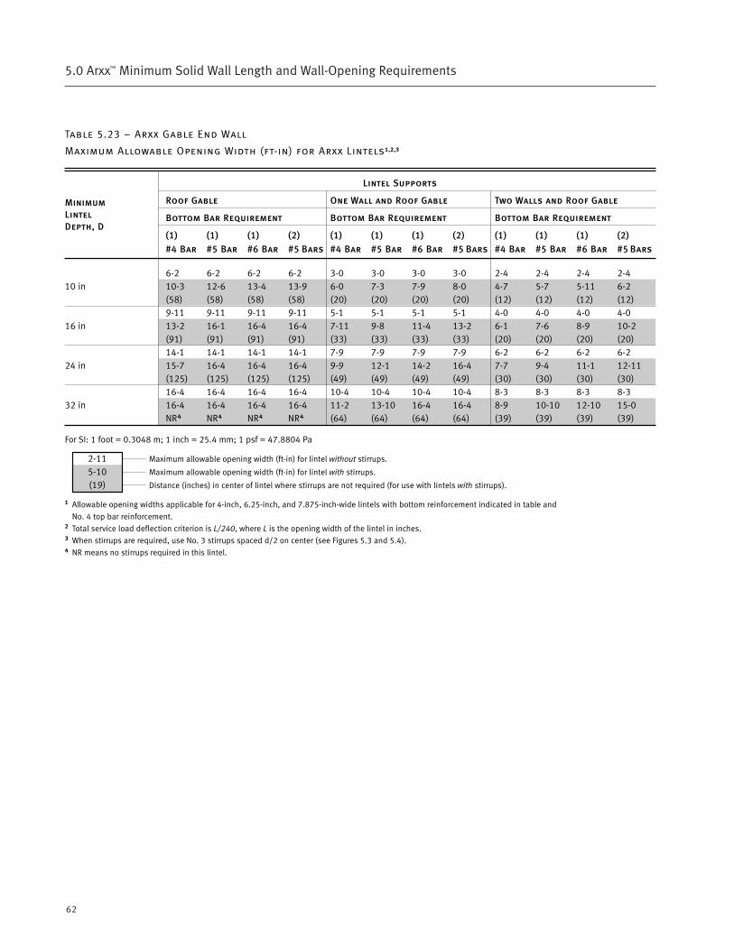
62
5.0 Arxx™ Minimum Solid Wall Length and Wall-Opening Requirements
Table 5.23 – Arxx Gable End Wall
Maximum Allowable Opening Width (ft-in) for Arxx Lintels1,2,3
Lintel Supports
Roof Gable One Wall and Roof Gable Two Walls and Roof Gable
Bottom Bar Requirement Bottom Bar Requirement Bottom Bar Requirement
(1) (1) (1) (2) (1) (1) (1) (2) (1) (1) (1) (2)
#4 Bar #5 Bar #6 Bar #5 Bars #4 Bar #5 Bar #6 Bar #5 Bars #4 Bar #5 Bar #6 Bar #5 Bars
6-2 6-2 6-2 6-2 3-0 3-0 3-0 3-0 2-4 2-4 2-4 2-410 in 10-3 12-6 13-4 13-9 6-0 7-3 7-9 8-0 4-7 5-7 5-11 6-2
(58) (58) (58) (58) (20) (20) (20) (20) (12) (12) (12) (12)9-11 9-11 9-11 9-11 5-1 5-1 5-1 5-1 4-0 4-0 4-0 4-0
16 in 13-2 16-1 16-4 16-4 7-11 9-8 11-4 13-2 6-1 7-6 8-9 10-2(91) (91) (91) (91) (33) (33) (33) (33) (20) (20) (20) (20)14-1 14-1 14-1 14-1 7-9 7-9 7-9 7-9 6-2 6-2 6-2 6-2
24 in 15-7 16-4 16-4 16-4 9-9 12-1 14-2 16-4 7-7 9-4 11-1 12-11(125) (125) (125) (125) (49) (49) (49) (49) (30) (30) (30) (30)16-4 16-4 16-4 16-4 10-4 10-4 10-4 10-4 8-3 8-3 8-3 8-3
32 in 16-4 16-4 16-4 16-4 11-2 13-10 16-4 16-4 8-9 10-10 12-10 15-0NR4 NR4 NR4 NR4 (64) (64) (64) (64) (39) (39) (39) (39)
For SI: 1 foot = 0.3048 m; 1 inch = 25.4 mm; 1 psf = 47.8804 Pa
1 Allowable opening widths applicable for 4-inch, 6.25-inch, and 7.875-inch-wide lintels with bottom reinforcement indicated in table and
No. 4 top bar reinforcement.2 Total service load deflection criterion is L/240, where L is the opening width of the lintel in inches.3 When stirrups are required, use No. 3 stirrups spaced d/2 on center (see Figures 5.3 and 5.4).4 NR means no stirrups required in this lintel.
MinimumLintelDepth, D
2-115-10(19)
Maximum allowable opening width (ft-in) for lintel without stirrups.
Maximum allowable opening width (ft-in) for lintel with stirrups.
Distance (inches) in center of lintel where stirrups are not required (for use with lintels with stirrups).
Arxx™ Connection Requirements
6.0
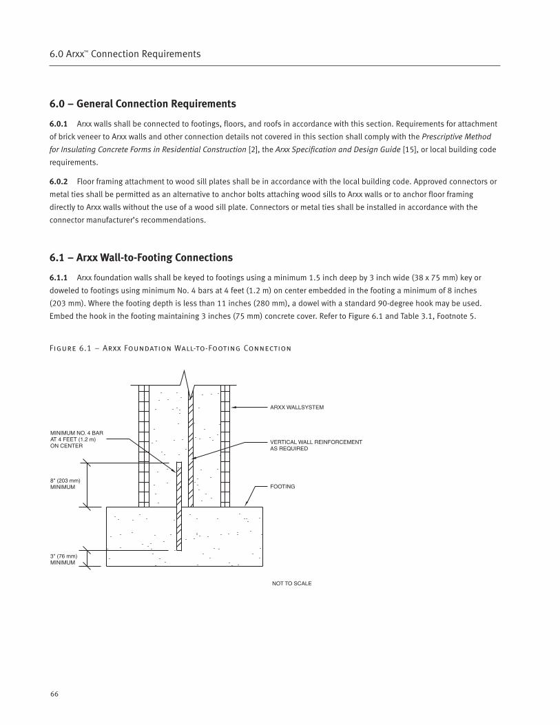
66
6.0 Arxx™ Connection Requirements
6.0 – General Connection Requirements
6.0.1 Arxx walls shall be connected to footings, floors, and roofs in accordance with this section. Requirements for attachment
of brick veneer to Arxx walls and other connection details not covered in this section shall comply with the Prescriptive Method
for Insulating Concrete Forms in Residential Construction [2], the Arxx Specification and Design Guide [15], or local building code
requirements.
6.0.2 Floor framing attachment to wood sill plates shall be in accordance with the local building code. Approved connectors or
metal ties shall be permitted as an alternative to anchor bolts attaching wood sills to Arxx walls or to anchor floor framing
directly to Arxx walls without the use of a wood sill plate. Connectors or metal ties shall be installed in accordance with the
connector manufacturer’s recommendations.
6.1 – Arxx Wall-to-Footing Connections
6.1.1 Arxx foundation walls shall be keyed to footings using a minimum 1.5 inch deep by 3 inch wide (38 x 75 mm) key or
doweled to footings using minimum No. 4 bars at 4 feet (1.2 m) on center embedded in the footing a minimum of 8 inches
(203 mm). Where the footing depth is less than 11 inches (280 mm), a dowel with a standard 90-degree hook may be used.
Embed the hook in the footing maintaining 3 inches (75 mm) concrete cover. Refer to Figure 6.1 and Table 3.1, Footnote 5.
Figure 6.1 – Arxx Foundation Wall-to-Footing Connection
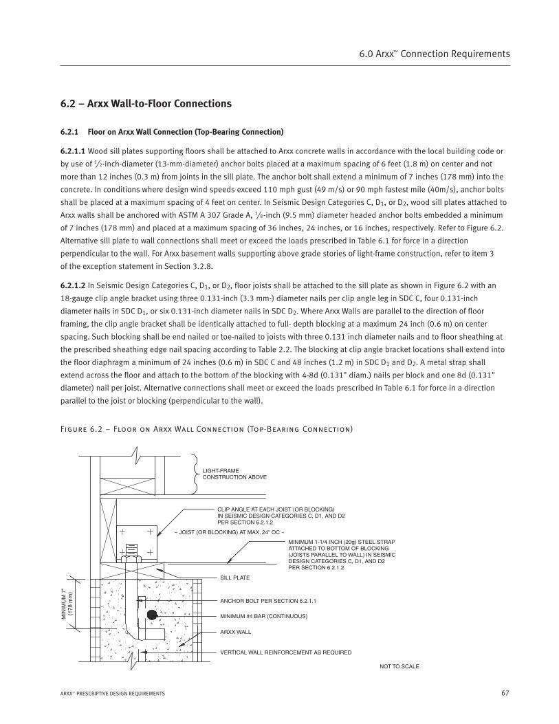
67ARXX™ PRESCRIPTIVE DESIGN REQUIREMENTS
6.0 Arxx™ Connection Requirements
6.2 – Arxx Wall-to-Floor Connections
6.2.1 Floor on Arxx Wall Connection (Top-Bearing Connection)
6.2.1.1 Wood sill plates supporting floors shall be attached to Arxx concrete walls in accordance with the local building code or
by use of 1⁄2-inch-diameter (13-mm-diameter) anchor bolts placed at a maximum spacing of 6 feet (1.8 m) on center and not
more than 12 inches (0.3 m) from joints in the sill plate. The anchor bolt shall extend a minimum of 7 inches (178 mm) into the
concrete. In conditions where design wind speeds exceed 110 mph gust (49 m/s) or 90 mph fastest mile (40m/s), anchor bolts
shall be placed at a maximum spacing of 4 feet on center. In Seismic Design Categories C, D1, or D2, wood sill plates attached to
Arxx walls shall be anchored with ASTM A 307 Grade A, 3⁄8-inch (9.5 mm) diameter headed anchor bolts embedded a minimum
of 7 inches (178 mm) and placed at a maximum spacing of 36 inches, 24 inches, or 16 inches, respectively. Refer to Figure 6.2.
Alternative sill plate to wall connections shall meet or exceed the loads prescribed in Table 6.1 for force in a direction
perpendicular to the wall. For Arxx basement walls supporting above grade stories of light-frame construction, refer to item 3
of the exception statement in Section 3.2.8.
6.2.1.2 In Seismic Design Categories C, D1, or D2, floor joists shall be attached to the sill plate as shown in Figure 6.2 with an
18-gauge clip angle bracket using three 0.131-inch (3.3 mm-) diameter nails per clip angle leg in SDC C, four 0.131-inch
diameter nails in SDC D1, or six 0.131-inch diameter nails in SDC D2. Where Arxx Walls are parallel to the direction of floor
framing, the clip angle bracket shall be identically attached to full- depth blocking at a maximum 24 inch (0.6 m) on center
spacing. Such blocking shall be end nailed or toe-nailed to joists with three 0.131 inch diameter nails and to floor sheathing at
the prescribed sheathing edge nail spacing according to Table 2.2. The blocking at clip angle bracket locations shall extend into
the floor diaphragm a minimum of 24 inches (0.6 m) in SDC C and 48 inches (1.2 m) in SDC D1 and D2. A metal strap shall
extend across the floor and attach to the bottom of the blocking with 4-8d (0.131" diam.) nails per block and one 8d (0.131"
diameter) nail per joist. Alternative connections shall meet or exceed the loads prescribed in Table 6.1 for force in a direction
parallel to the joist or blocking (perpendicular to the wall).
Figure 6.2 – Floor on Arxx Wall Connection (Top-Bearing Connection)
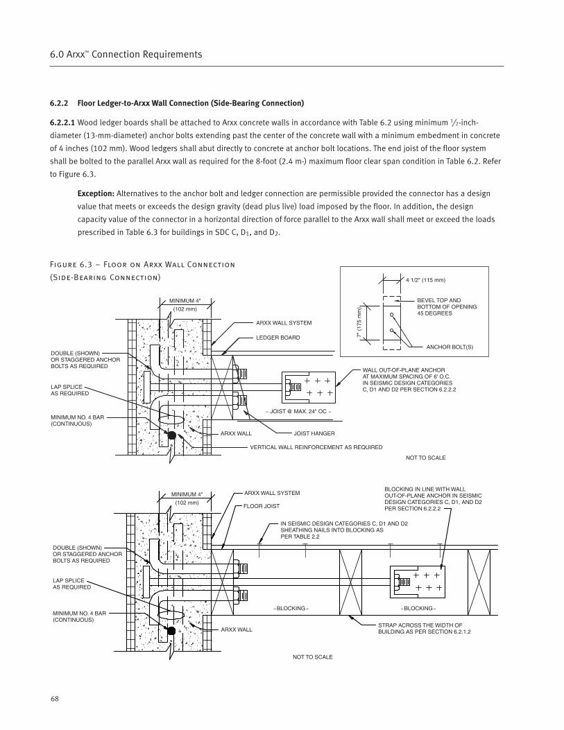
68
6.0 Arxx™ Connection Requirements
6.2.2 Floor Ledger-to-Arxx Wall Connection (Side-Bearing Connection)
6.2.2.1 Wood ledger boards shall be attached to Arxx concrete walls in accordance with Table 6.2 using minimum 1⁄2-inch-
diameter (13-mm-diameter) anchor bolts extending past the center of the concrete wall with a minimum embedment in concrete
of 4 inches (102 mm). Wood ledgers shall abut directly to concrete at anchor bolt locations. The end joist of the floor system
shall be bolted to the parallel Arxx wall as required for the 8-foot (2.4 m-) maximum floor clear span condition in Table 6.2. Refer
to Figure 6.3.
Exception: Alternatives to the anchor bolt and ledger connection are permissible provided the connector has a design
value that meets or exceeds the design gravity (dead plus live) load imposed by the floor. In addition, the design
capacity value of the connector in a horizontal direction of force parallel to the Arxx wall shall meet or exceed the loads
prescribed in Table 6.3 for buildings in SDC C, D1, and D2.
Figure 6.3 – Floor on Arxx Wall Connection
(Side-Bearing Connection)
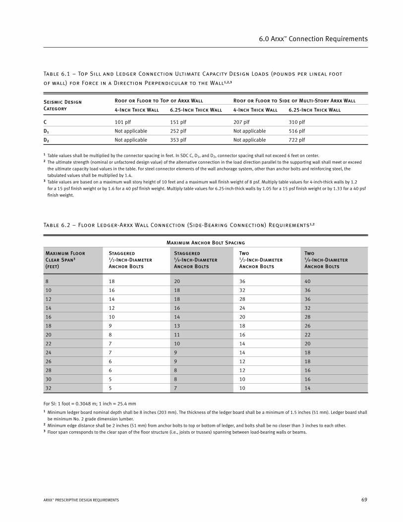
69ARXX™ PRESCRIPTIVE DESIGN REQUIREMENTS
6.0 Arxx™ Connection Requirements
Table 6.1 – Top Sill and Ledger Connection Ultimate Capacity Design Loads (pounds per lineal foot
of wall) for Force in a Direction Perpendicular to the Wall1,2,3
Seismic Design Roof or Floor to Top of Arxx Wall Roof or Floor to Side of Multi-Story Arxx Wall
Category 4-Inch Thick Wall 6.25-Inch Thick Wall 4-Inch Thick Wall 6.25-Inch Thick Wall
C 101 plf 151 plf 207 plf 310 plf
D1 Not applicable 252 plf Not applicable 516 plf
D2 Not applicable 353 plf Not applicable 722 plf
1 Table values shall be multiplied by the connector spacing in feet. In SDC C, D1, and D2, connector spacing shall not exceed 6 feet on center.2 The ultimate strength (nominal or unfactored design value) of the alternative connection in the load direction parallel to the supporting wall shall meet or exceed
the ultimate capacity load values in the table. For steel connector elements of the wall anchorage system, other than anchor bolts and reinforcing steel, the
tabulated values shall be multiplied by 1.4.3 Table values are based on a maximum wall story height of 10 feet and a maximum wall finish weight of 8 psf. Multiply table values for 4-inch-thick walls by 1.2
for a 15 psf finish weight or by 1.6 for a 40 psf finish weight. Multiply table values for 6.25-inch-thick walls by 1.05 for a 15 psf finish weight or by 1.33 for a 40 psf
finish weight.
Table 6.2 – Floor Ledger-Arxx Wall Connection (Side-Bearing Connection) Requirements1,2
Maximum Anchor Bolt Spacing
Maximum Floor Staggered Staggered Two TwoClear Span3 1⁄2-Inch-Diameter 5⁄8-Inch-Diameter 1⁄2-Inch-Diameter 5⁄8-Inch-Diameter(feet) Anchor Bolts Anchor Bolts Anchor Bolts Anchor Bolts
8 18 20 36 40
10 16 18 32 36
12 14 18 28 36
14 12 16 24 32
16 10 14 20 28
18 9 13 18 26
20 8 11 16 22
22 7 10 14 20
24 7 9 14 18
26 6 9 12 18
28 6 8 12 16
30 5 8 10 16
32 5 7 10 14
For SI: 1 foot = 0.3048 m; 1 inch = 25.4 mm1 Minimum ledger board nominal depth shall be 8 inches (203 mm). The thickness of the ledger board shall be a minimum of 1.5 inches (51 mm). Ledger board shall
be minimum No. 2 grade dimension lumber.2 Minimum edge distance shall be 2 inches (51 mm) from anchor bolts to top or bottom of ledger, and bolts shall be no closer than 3 inches to each other.3 Floor span corresponds to the clear span of the floor structure (i.e., joists or trusses) spanning between load-bearing walls or beams.
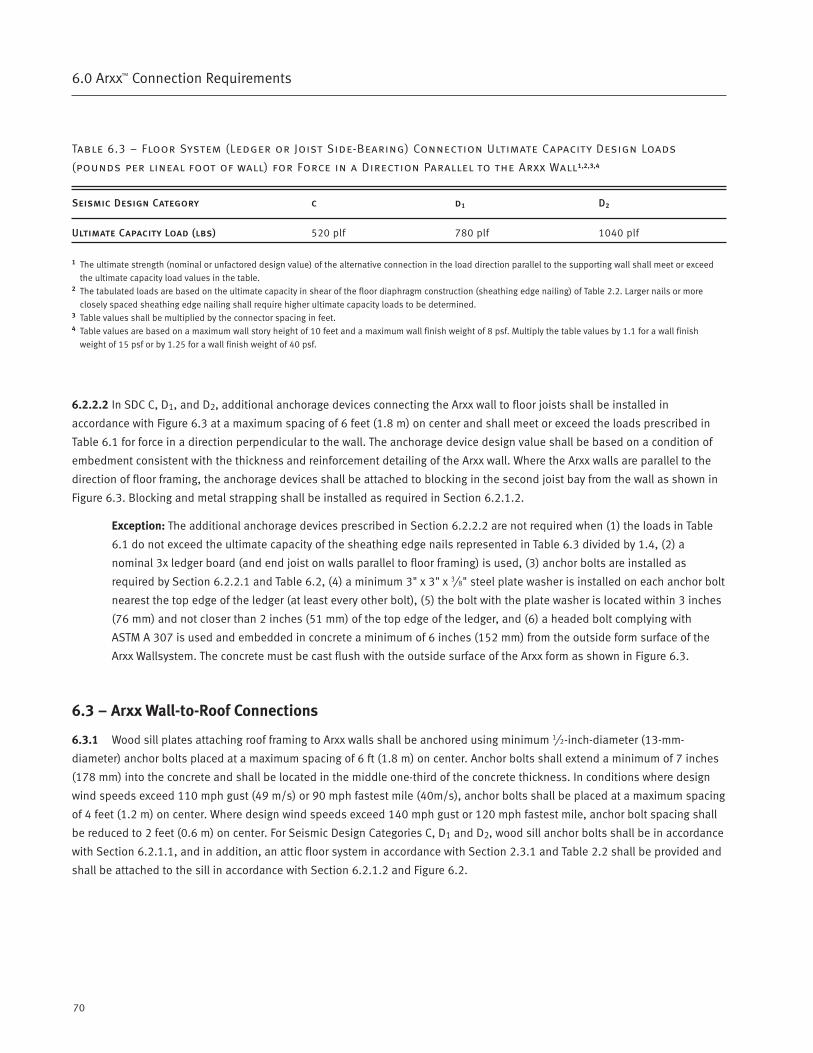
70
6.0 Arxx™ Connection Requirements
Table 6.3 – Floor System (Ledger or Joist Side-Bearing) Connection Ultimate Capacity Design Loads
(pounds per lineal foot of wall) for Force in a Direction Parallel to the Arxx Wall1,2,3,4
Seismic Design Category c d1 D2
Ultimate Capacity Load (lbs) 520 plf 780 plf 1040 plf
1 The ultimate strength (nominal or unfactored design value) of the alternative connection in the load direction parallel to the supporting wall shall meet or exceed
the ultimate capacity load values in the table.2 The tabulated loads are based on the ultimate capacity in shear of the floor diaphragm construction (sheathing edge nailing) of Table 2.2. Larger nails or more
closely spaced sheathing edge nailing shall require higher ultimate capacity loads to be determined.3 Table values shall be multiplied by the connector spacing in feet.4 Table values are based on a maximum wall story height of 10 feet and a maximum wall finish weight of 8 psf. Multiply the table values by 1.1 for a wall finish
weight of 15 psf or by 1.25 for a wall finish weight of 40 psf.
6.2.2.2 In SDC C, D1, and D2, additional anchorage devices connecting the Arxx wall to floor joists shall be installed in
accordance with Figure 6.3 at a maximum spacing of 6 feet (1.8 m) on center and shall meet or exceed the loads prescribed in
Table 6.1 for force in a direction perpendicular to the wall. The anchorage device design value shall be based on a condition of
embedment consistent with the thickness and reinforcement detailing of the Arxx wall. Where the Arxx walls are parallel to the
direction of floor framing, the anchorage devices shall be attached to blocking in the second joist bay from the wall as shown in
Figure 6.3. Blocking and metal strapping shall be installed as required in Section 6.2.1.2.
Exception: The additional anchorage devices prescribed in Section 6.2.2.2 are not required when (1) the loads in Table
6.1 do not exceed the ultimate capacity of the sheathing edge nails represented in Table 6.3 divided by 1.4, (2) a
nominal 3x ledger board (and end joist on walls parallel to floor framing) is used, (3) anchor bolts are installed as
required by Section 6.2.2.1 and Table 6.2, (4) a minimum 3" x 3" x 3⁄8" steel plate washer is installed on each anchor bolt
nearest the top edge of the ledger (at least every other bolt), (5) the bolt with the plate washer is located within 3 inches
(76 mm) and not closer than 2 inches (51 mm) of the top edge of the ledger, and (6) a headed bolt complying with
ASTM A 307 is used and embedded in concrete a minimum of 6 inches (152 mm) from the outside form surface of the
Arxx Wallsystem. The concrete must be cast flush with the outside surface of the Arxx form as shown in Figure 6.3.
6.3 – Arxx Wall-to-Roof Connections
6.3.1 Wood sill plates attaching roof framing to Arxx walls shall be anchored using minimum 1⁄2-inch-diameter (13-mm-
diameter) anchor bolts placed at a maximum spacing of 6 ft (1.8 m) on center. Anchor bolts shall extend a minimum of 7 inches
(178 mm) into the concrete and shall be located in the middle one-third of the concrete thickness. In conditions where design
wind speeds exceed 110 mph gust (49 m/s) or 90 mph fastest mile (40m/s), anchor bolts shall be placed at a maximum spacing
of 4 feet (1.2 m) on center. Where design wind speeds exceed 140 mph gust or 120 mph fastest mile, anchor bolt spacing shall
be reduced to 2 feet (0.6 m) on center. For Seismic Design Categories C, D1 and D2, wood sill anchor bolts shall be in accordance
with Section 6.2.1.1, and in addition, an attic floor system in accordance with Section 2.3.1 and Table 2.2 shall be provided and
shall be attached to the sill in accordance with Section 6.2.1.2 and Figure 6.2.
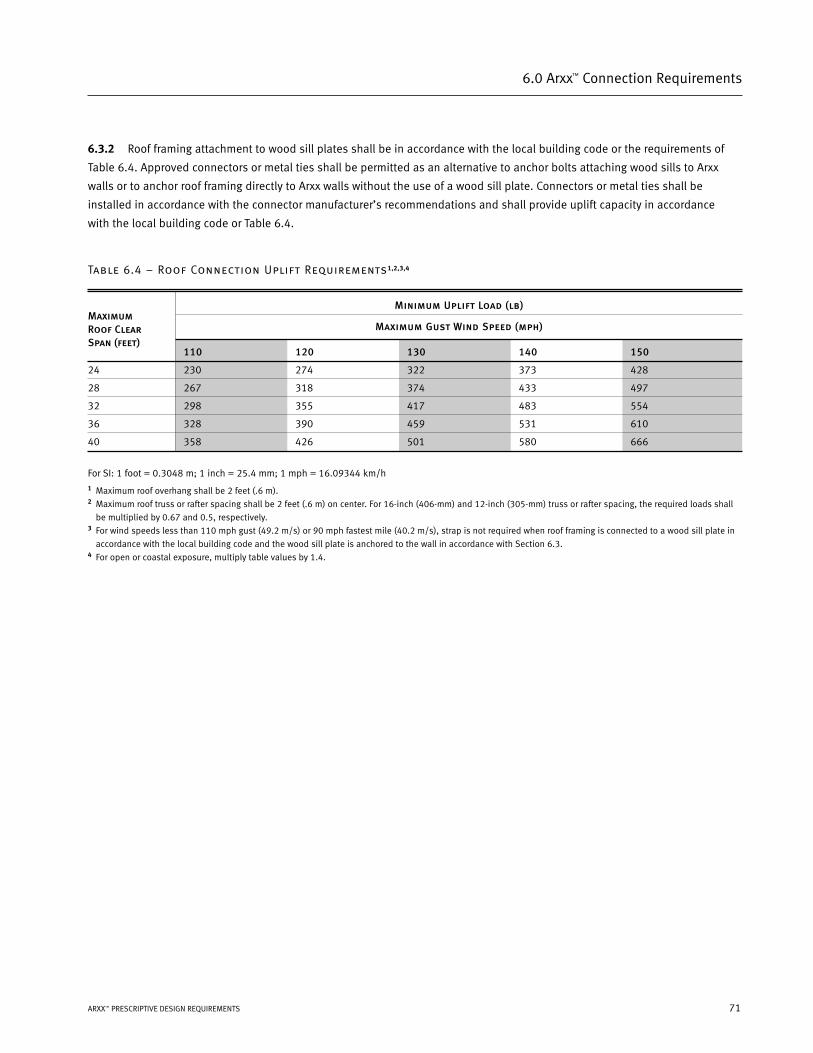
6.3.2 Roof framing attachment to wood sill plates shall be in accordance with the local building code or the requirements of
Table 6.4. Approved connectors or metal ties shall be permitted as an alternative to anchor bolts attaching wood sills to Arxx
walls or to anchor roof framing directly to Arxx walls without the use of a wood sill plate. Connectors or metal ties shall be
installed in accordance with the connector manufacturer’s recommendations and shall provide uplift capacity in accordance
with the local building code or Table 6.4.
Table 6.4 – Roof Connection Uplift Requirements1,2,3,4
Minimum Uplift Load (lb)
Maximum Gust Wind Speed (mph)
110 120 130 140 150
24 230 274 322 373 428
28 267 318 374 433 497
32 298 355 417 483 554
36 328 390 459 531 610
40 358 426 501 580 666
For SI: 1 foot = 0.3048 m; 1 inch = 25.4 mm; 1 mph = 16.09344 km/h1 Maximum roof overhang shall be 2 feet (.6 m).2 Maximum roof truss or rafter spacing shall be 2 feet (.6 m) on center. For 16-inch (406-mm) and 12-inch (305-mm) truss or rafter spacing, the required loads shall
be multiplied by 0.67 and 0.5, respectively.3 For wind speeds less than 110 mph gust (49.2 m/s) or 90 mph fastest mile (40.2 m/s), strap is not required when roof framing is connected to a wood sill plate in
accordance with the local building code and the wood sill plate is anchored to the wall in accordance with Section 6.3.4 For open or coastal exposure, multiply table values by 1.4.
71ARXX™ PRESCRIPTIVE DESIGN REQUIREMENTS
6.0 Arxx™ Connection Requirements
MaximumRoof ClearSpan (feet)

References
7.0
PDR Section 6-7 7/31/06 11:27 AM Page 73
74
7.0 References
[1] ASTM E 380 Standard Practice for Use of the International System of Units (SI) (the Modernized Metric System), American
Society for Testing and Materials (ASTM), West Conshohocken, Pennsylvania. 1992.
[2] Prescriptive Method for Insulating Concrete Forms in Residential Construction, prepared for the U.S. Department of
Housing and Urban Development, Portland Cement Association, and the National Association of Home Builders, by the
NAHB Research Center, Inc., Upper Marlboro, Maryland. 1998.
[3] Building Code Requirements for Structural Concrete (ACI 318), American Concrete Institute, Detroit, Michigan. 2002.
[4] Structural Design of Insulating Concrete Form Walls in Residential Construction, prepared by NAHB Research Center, Inc.,
for the Portland Cement Association, Skokie, Illinois. 1998.
[5] Minimum Design Loads for Buildings and Other Structures (ASCE 7-98), American Society of Civil Engineers, New York,
New York. 1999.
[6] ASTM C 31/C 31M-96 Standard Practice for Making and Curing Concrete Test Specimens in the Field, American Society for
Testing and Materials (ASTM), West Conshohocken, Pennsylvania. 1997.
[7] ASTM C 39-96 Standard Test Method for Compressive Strength of Cylindrical Concrete Specimens, American Society for
Testing and Materials (ASTM), West Conshohocken, Pennsylvania. 1996.
[8] ASTM C 143-90a Standard Test Method for Slump of Hydraulic Cement, American Society for Testing and Materials
(ASTM), West Conshohocken, Pennsylvania. 1978.
[9] ASTM A 370-96 Standard Test Methods and Definitions for Mechanical Testing of Steel Products, American Society for
Testing and Materials (ASTM), West Conshohocken, Pennsylvania. 1996.
[10] ASTM C 94-96e1 Standard Specification for Ready-Mixed Concrete, American Society for Testing and Materials (ASTM),
West Conshohocken, Pennsylvania. 1996.
[11] ASTM A 615 / A 615 M-96a Standard Specification for Deformed and Plain Billet-Steel Bars for Concrete Reinforcement,
American Society for Testing and Materials (ASTM), West Conshohocken, Pennsylvania. 1996.
[12] ASTM A 616 / A 616 M-96 Standard Specification for Rail-Steel Deformed and Plain Bars for Concrete Reinforcement,
American Society for Testing and Materials (ASTM), West Conshohocken, Pennsylvania. 1996.
[13] ASTM A 617 / A 617 M-96a Standard Specification for Axle-Steel Deformed and Plain Bars for Concrete Reinforcement,
American Society for Testing and Materials (ASTM), West Conshohocken, Pennsylvania. 1996.
[14] ASTM A 706 / A 706 M-96b Standard Specification for Low-Alloy Steel Deformed and Plain Bars for Concrete
Reinforcement, American Society for Testing and Materials (ASTM), West Conshohocken, Pennsylvania. 1996.
[15] Arxx Detailing and Specification Guide, Arxx Building Products, Inc., Cobourg, Ontario, Canada. 1999.
[16] International Residential Code (IRC), International Code Council, Inc., Falls Church, Virginia. 2000.
[17] International Residential Code (IRC), International Code Council, Inc., Falls Church, Virginia. 2003.
[18] International Building Code (IBC), International Code Council, Inc., Falls Church, Virginia. 2000.
[19] International Building Code (IBC), International Code Council, Inc., Falls Church, Virginia. 2003.
[20] Uniform Building Code (UBC), International Conference of Building Officials (ICBO), Whittier, California. 1997.
PDR Section 6-7 7/31/06 11:27 AM Page 74
75ARXX® PRESCRIPTIVE DESIGN REQUIREMENTS
7.0 References
[21] International One- and Two-Family Dwelling Code, International Code Council, Falls Church, Virginia, 1998.
(previous versions provided by Council of American Building Officials).
[22] Standard Building Code (SBC), Southern Building Code Congress International, Birmingham, Alabama. 1999.
[23] National Building Code (NBC), Building Officials and Code Administrators International, Country Club Hills, Illinois. 1999.
PDR Section 6-7 7/31/06 11:27 AM Page 75