Embed Size (px)
Citation preview
Copyright 2010 Aruba Networks 1
发
Introduction
The Aruba AirMesh device is a multi-function, wireless mesh router capable of forming a wireless
network with end-user devices, other AirMesh devices, and a wired network. The AirMesh device
includes the following features:
1. Connecting to other AirMesh devices to form the backbone of a wireless mesh network;
2. Connecting to a wired network via an Ethernet connection
3. Serving as an Wi-Fi Access Point (AP) for end-user devices ;
4. Used as client device to connect to standard 802.11 networks.
When the above functions are properly configured, AirMesh devices form a wide-area wireless
network that allows end-user devices located inside it to connect to the internet as well as each
other, and offer a diverse set of services such as web browsing, file sharing, VOIP, and video
streaming.
This document describes the most commonly used deployment procedures of AirMesh devices.
These procedures include the following steps:
1. Initial setup through USB Console to set the management IP via the command-line interface;
2. Using WebUI to change host name.
3. Configuring a point-to-point network.
4. Troubleshooting a point-to-point network.
5. Building a four nodes mesh network.
6. Configuring an access network.
7. Configuring an AirMesh device as a client device.
Before You Begin
1. Review the contents of your AirMesh device shipment to ensure that you have received the
following:
Aruba AirMesh device with appropriate power cord and an USB console cable.
Aruba MeshOS 4.2 Quick Start Guide (this document).
Aruba MeshOS End User License Agreement
2. Read the Aruba Mesh OS End User License Agreement.
Check the customer support web site for the latest software upgrades and documentation upgrades:
https://support.arubanetworks.com.
Initial Setup through USB Console
Aruba AirMesh device has a USB port serving as the console port. Before you connect a terminal
or PC workstation running a terminal emulation program to the USB console port on the AirMesh
device, you should download and install the USB to Console conversion software. For both Linux
and Windows operating systems, Aruba has different USB to Console conversion software
available from the Aruba website.
The USB Console port connection allows you to do the basic configurations that are required to connect the AirMesh
Aruba MeshOS 4.2 Quick Start Guide
NOTE
NOTE
2 Copyright 2010 Aruba Networks
device to the network. You can use the WebUI for further configuration.
To run the basic configuration from a USB Console connection:
1. Configure the terminal communications settings according to the following table.
Table 1: Terminal Communication Settings
Baud Rate Data Bits Parity Stop Bits Flow Control
115200 8 None 1 None
2. Connect your terminal or PC/workstation to the USB Console port on the AirMesh device
using an USB cable.
3. Boot up the AirMesh device. Log into the AirMesh device using the default credentials,
username:root and password:public. Then, enter “enable” to allow you into the Privileged
EXEC mode. After logged in, you should see a screen similar to the following:
Privileged EXEC mode has commands to view configuration, run diagnostics, upgrade, restore factory default, and
reboot the router.
4. Enter CONFIGURATION mode. Enter “configure terminal” in the Privileged EXEC mode to
allow you into the CONFIGURATION mode.
CONFIGURATION mode enables you to change configuration of the router.
5. Configuring the Management IP.
In factory default, the Management IP is the address of interface vlan 1, which is configured
to obtain its IP address using DHCP. You need to manually reconfigure interface vlan 1 to
use static IP address.
Following commands must be used to configure the Management IP.
After configuration, you can use the “show” command to verify the new Management IP
address.
(config)#interface vlan 1
(config)# interface vlan 1
(config-vlan)# ip address 192.168.11.1/24
(config-vlan)# end
# write memory
#
# configure terminal
(config)#
MSR1200-2b:56:2d login: root
Password:
Hello, Welcome to Aruba CLI
> enable
#
NOTE
NOTE
Aruba MeshOS 4.2 | Quick Start Guide 3
Using WebUI to Change Hostname
Before you use WebUI to configure the AirMesh device, you must ensure that the router can be
accessed via Ethernet, and has been assigned the Management IP address.
You can connect a PC or workstation directly to the Ethernet port on the AirMesh device and
connect to the Management IP address through a Web browser to change config.
Accessing the Web Interface
1. Connect your PC or workstation to the Ethernet port on the AirMesh device.
2. On your PC or workstation, open a Web browser to https://[Management IP Address ]
The WebUI requires Internet Explorer 6.0 or above with JavaScript enabled. Other browsers may work but with
limited functionality and are therefore not supported. The optimal resolution is 1024 X 768 or above.
3. The AirMesh device contains a default server certificate. At the Security Alert, click Yes to
proceed with the router.
4. At the WebUI login page, enter the default credentials username “root” and password
“public”.
Using WebUI to change the Hostname
1. After login, navigate to the Basic Setting page.
2. Select the Host Name text field, and enter the new hostname.
3. Click the Apply Changes button to save the new hostname.
In WebUI, configuration changes are automatically saved after clicking the Apply Change button.
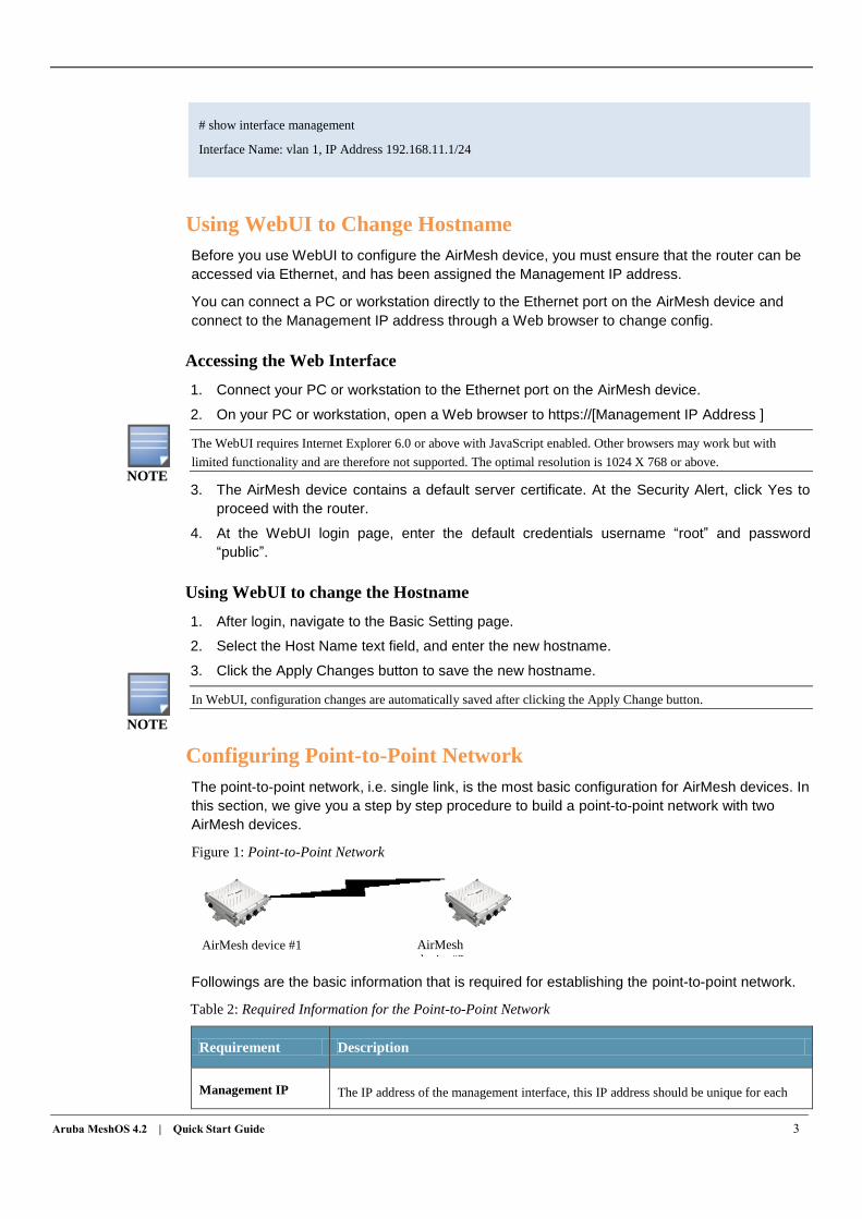
Configuring Point-to-Point Network
The point-to-point network, i.e. single link, is the most basic configuration for AirMesh devices. In
this section, we give you a step by step procedure to build a point-to-point network with two
AirMesh devices.
Figure 1: Point-to-Point Network
Followings are the basic information that is required for establishing the point-to-point network.
Table 2: Required Information for the Point-to-Point Network
Requirement Description
Management IP The IP address of the management interface, this IP address should be unique for each
AirMesh device #1 AirMesh
device#2
# show interface management
Interface Name: vlan 1, IP Address 192.168.11.1/24
NOTE
NOTE
4 Copyright 2010 Aruba Networks
AirMesh device.
NOTE: In factory default, the interface vlan 1 is set to the management interface, and
it's IP address is used as the management IP.
Mesh-ID
Mesh identifier of a Mesh network. In factory default, the Mesh-ID is “DefaultMesh”.
NOTE: All theAirMesh devices in the same Mesh network should be configured with
the same Mesh-ID.
hostname
A name by which the AirMesh device will be referenced. You can specify a name of up
to 32 characters. In factory default, the hostname is in form of “MODEL-AA:BB:CC”,
where MODEL is the router model name and AA:BB:CC is the last three bytes of the
router’s MAC address. For example, an MSR2000 with MAC address
00:17:7B:EA:5B:C3 would have a default hostname of “MSR2000-EA:5B:C3.”
NOTE: It is optional, but highly recommended.
Security Type All AirMesh devices in the same Mesh network must be configured with the same
security type and security key.
NOTE: It is optional, but highly recommended. Security Key
Preferred Link
The preferred link is used to control link establishment according to pre-defined rules,
such as local radio, remote MSR router and remote radio index, channel etc. The
preferred link can be used to improve the link stability of the mesh network.
NOTE: It is optional.
Max Allowed Links
This is a radio parameter used to limit the max allowed links which can be created on a
special radio when the radio is enable auto WDS meshing.
NOTE: It is optional.
Sample Point-to-Point Network Configuration
In order to establish a point-to-point mesh network as figure 1, the required configuration for each
AirMesh device is summarized as following:
Table 3: sample point-to-point network configuration
Configuration AirMesh Device #1 AirMesh device #2
Host Name Node-1 Node-2
Mesh-ID PtP-Mesh PtP-Mesh
Management IP 192.168.11.1/24 192.168.11.2/24
Security Type WPA2-PSK WPA2-PSK
Security Key PointToPointMesh PointToPointMesh
Preferred Link 0
Neighbor Host Name: Node-2
Preferred Radio: 1 (For MSR1200/
MSR2000/MSR4000)
0 (For MST200)
Preferred Channel : 149
Neighbor Host Name: Node-1
Preferred Radio: 1 (For MSR1200/
MSR2000/MSR4000)
0 (For MST200)
Preferred Channel : 149
Aruba MeshOS 4.2 | Quick Start Guide 5
Max Allowed Links Radio 0: 1 Radio 0: 1
The above configuration should be done on each AirMesh device separately. For each MSR router, you should follow
these steps.
Configuring Management IP Address
Configure static Management IP address 192.168.11.1/24 on interface vlan 1 for AirMesh
device#1, and 192.168.11.2/24 for AIrMesh device#2 using USB Console.
For detailed configuration steps, see “Initial Setup through USB Console” on page 1.
Configuring Hostname
Configure hostname Node-1 for AirMesh device#1, and Node-2 for AirMesh device#2 using
WebUI.
For detailed configuration steps, see “Using WebUI to Change Hostname” on page 3.
Configuring Mesh-ID
The Mesh-ID identify the mesh network which the AirMesh devices to join to. This Mesh-ID
should be different from any other Mesh networks that may be in the same general area. The two
AirMesh devices should be configured with the same Mesh-ID “PtP-Mesh”. AirMesh devices with
different Mesh-ID will fail to mesh with each other.
To configure the Mesh-ID:
1. Login to the WebUI, navigate to the Wireless Settings > Mesh page.
2. In the Basic tab of the Mesh page, select the Mesh Network ID text field, and enter the new
Mesh-ID “PtP-Mesh”.
3. Click the Apply Changes button to save the new Mesh-ID.
Configuring Mesh Security
AirMesh device supports a number of security types to secure mesh links, which include Open
WEP, Share WEP, WPA-PSK, and WPA2-PSK.
Similar to configuration of Mesh-ID, configuring the mesh security requires the two AirMesh
devices in the mesh network using the same type and key string. AirMesh devices with different
security configuration will fail to mesh with each other.
As an example, you will be directed to use WPA2-PSK.
To configure the mesh security:
1. Login to the Web UI, navigate to the Wireless Settings > Mesh page.
2. In the Security tab of the Mesh page, select “WPA2” for Security Type field.
3. Select “WPA-PSK, ASCII Key” for the WPA type field.
4. Select the PSK Key string text field, and enter the key string “PointToPointMesh”
5. Click the Apply Changes button to save the new Security configuration.
For WPA-PSK, the configuration steps are almost the same as WPA2-PSK. For Open-WEP and Share WEP, there
need extra steps to add the pre-defined WEP keys. For detailed steps, see the “Mesh configuration” chapter in the
Aruba Mesh Router Web-based Configuration Guide.
NOTE
NOTE
6 Copyright 2010 Aruba Networks
Configuring Preferred Link (Optional)
Configuring preferred link is optional, but highly recommended.
The above steps have helped you to establish a basic mesh profile on each router. With the mesh
profile, Node-1 and Node-2 can form a point-to-point link. But there is no control over which radio
(0 or 1) on each router is specified for establishing the link. Although this level of control is not
required, establishing links on specific radio on each MSR router can often improve the link
stability of the mesh network.
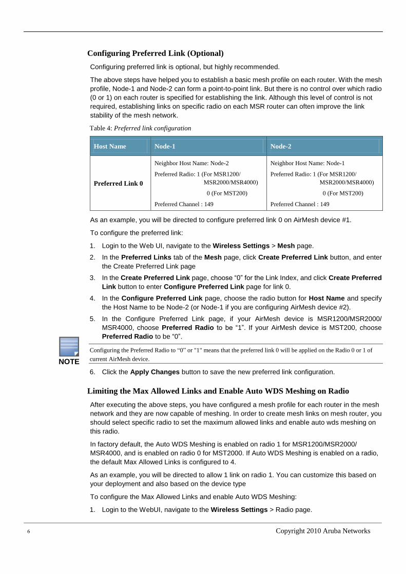
Table 4: Preferred link configuration
Host Name Node-1 Node-2
Preferred Link 0
Neighbor Host Name: Node-2
Preferred Radio: 1 (For MSR1200/
MSR2000/MSR4000)
0 (For MST200)
Preferred Channel : 149
Neighbor Host Name: Node-1
Preferred Radio: 1 (For MSR1200/
MSR2000/MSR4000)
0 (For MST200)
Preferred Channel : 149
As an example, you will be directed to configure preferred link 0 on AirMesh device #1.
To configure the preferred link:
1. Login to the Web UI, navigate to the Wireless Settings > Mesh page.
2. In the Preferred Links tab of the Mesh page, click Create Preferred Link button, and enter
the Create Preferred Link page
3. In the Create Preferred Link page, choose “0” for the Link Index, and click Create Preferred
Link button to enter Configure Preferred Link page for link 0.
4. In the Configure Preferred Link page, choose the radio button for Host Name and specify
the Host Name to be Node-2 (or Node-1 if you are configuring AirMesh device #2).
5. In the Configure Preferred Link page, if your AirMesh device is MSR1200/MSR2000/
MSR4000, choose Preferred Radio to be “1”. If your AirMesh device is MST200, choose
Preferred Radio to be “0”.
Configuring the Preferred Radio to “0” or "1" means that the preferred link 0 will be applied on the Radio 0 or 1 of
current AirMesh device.
6. Click the Apply Changes button to save the new preferred link configuration.
Limiting the Max Allowed Links and Enable Auto WDS Meshing on Radio
After executing the above steps, you have configured a mesh profile for each router in the mesh
network and they are now capable of meshing. In order to create mesh links on mesh router, you
should select specific radio to set the maximum allowed links and enable auto wds meshing on
this radio.
In factory default, the Auto WDS Meshing is enabled on radio 1 for MSR1200/MSR2000/
MSR4000, and is enabled on radio 0 for MST2000. If Auto WDS Meshing is enabled on a radio,
the default Max Allowed Links is configured to 4.
As an example, you will be directed to allow 1 link on radio 1. You can customize this based on
your deployment and also based on the device type
To configure the Max Allowed Links and enable Auto WDS Meshing:
1. Login to the WebUI, navigate to the Wireless Settings > Radio page.
NOTE
Aruba MeshOS 4.2 | Quick Start Guide 7
2. Click the Radio 1 link to navigate to the Basic tab page of radio configuration for radio 1.
3. Click the Backhaul tab to navigate to the Backhaul tab page of radio configuration for radio
0.
4. Select Enable Auto WDS Meshing checkbox, and enter “1” for Max Allowed Links field.
5. Click the Apply Changes button to save these changes. .
Troubleshooting Point-to-Point Network
During the configuration or staging of a mesh network it is possible that you could have some
issues with forming mesh links between the nodes or other setup issues. Some of the common
reasons for this include:
Configuring a different Mesh-ID on the two nodes.
Mismatch in the mesh security configured on the two nodes.
Radio on either of the nodes is down
Auto WDS is disabled on a radio.
In this section, you will be directed to use a series of troubleshooting procedure to figure out the
reason for the downed link and fix it. These procedures include:
Checking active links on each node.
Verifying mesh configuration on each node.
Getting device list within same Mesh-ID
Getting radio status of each radio on each node
Getting neighbor nodes
Help to align antenna in real deployment
Checking Active Links on Each Node
Before you do any troubleshooting, you should get active links on each node and check whether
these active links are what you expect.
To get active links on a AirMesh device:
1. Login to the WebUI, navigate to the Troubleshooting > Tools page.
2. In the RF Management field, select “Active Links” from the dropdown list.
3. Click the Execute button on the right-side corresponding to the RF Management field to get
the active links information.
4. The result will be displayed on the bottom of the page. If there is no active link on this node,
the display area is blank.
Figure 2 gives an example and shows the active links on AirMesh device “Node-1” by executing
the above steps.
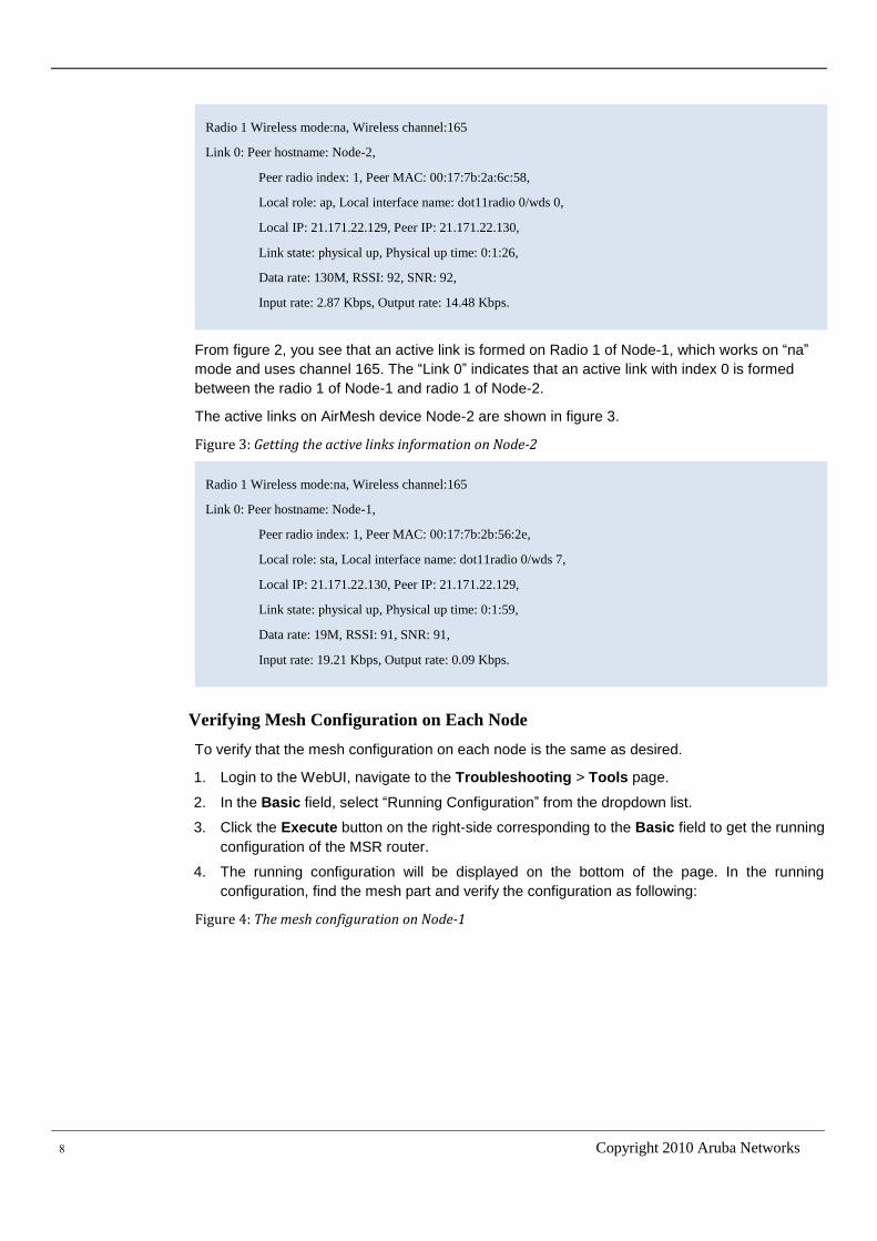
Figure 2: Getting the active links information on Node-1
8 Copyright 2010 Aruba Networks
From figure 2, you see that an active link is formed on Radio 1 of Node-1, which works on “na”
mode and uses channel 165. The “Link 0” indicates that an active link with index 0 is formed
between the radio 1 of Node-1 and radio 1 of Node-2.
The active links on AirMesh device Node-2 are shown in figure 3.
Figure 3: Getting the active links information on Node-2
Verifying Mesh Configuration on Each Node
To verify that the mesh configuration on each node is the same as desired.
1. Login to the WebUI, navigate to the Troubleshooting > Tools page.
2. In the Basic field, select “Running Configuration” from the dropdown list.
3. Click the Execute button on the right-side corresponding to the Basic field to get the running
configuration of the MSR router.
4. The running configuration will be displayed on the bottom of the page. In the running
configuration, find the mesh part and verify the configuration as following:
Figure 4: The mesh configuration on Node-1
Radio 1 Wireless mode:na, Wireless channel:165
Link 0: Peer hostname: Node-1,
Peer radio index: 1, Peer MAC: 00:17:7b:2b:56:2e,
Local role: sta, Local interface name: dot11radio 0/wds 7,
Local IP: 21.171.22.130, Peer IP: 21.171.22.129,
Link state: physical up, Physical up time: 0:1:59,
Data rate: 19M, RSSI: 91, SNR: 91,
Input rate: 19.21 Kbps, Output rate: 0.09 Kbps.
Radio 1 Wireless mode:na, Wireless channel:165
Link 0: Peer hostname: Node-2,
Peer radio index: 1, Peer MAC: 00:17:7b:2a:6c:58,
Local role: ap, Local interface name: dot11radio 0/wds 0,
Local IP: 21.171.22.129, Peer IP: 21.171.22.130,
Link state: physical up, Physical up time: 0:1:26,
Data rate: 130M, RSSI: 92, SNR: 92,
Input rate: 2.87 Kbps, Output rate: 14.48 Kbps.
Aruba MeshOS 4.2 | Quick Start Guide 9
Getting Device List within Same Mesh-ID
You can get the device list which has the same Mesh-ID as the current node. This will give you
information on the AirMesh devices that have formed links with the current node. From the device
list on each node, you can get the connectivity relationship among all the nodes.
To get the device list in the same Mesh-ID
1. Login to the WebUI, navigate to the Troubleshooting > Tools page.
2. In the Basic field, select “Mesh Node List” from the dropdown list.
3. Click the Execute button on the right-side corresponding to the Basic field to get all the
devices with the same mesh-id as current node.
Figure 5 : Device List of Node-1
Figure 6: Device List of Node-2
From the above figures, you see that the Node-1 and Node-2 are configured with the same mesh
profile and in the same network.
Getting Radio Status of Each Radio
After following the steps listed before, it is possible that some MSR router did not form links as
planned. To troubleshoot this problem you can check the radio status of these AirMesh devices
and find the reason.
To get the radio status of each radio
1. Login to the WebUI, navigate to the Troubleshooting > Tools page.
2. In the Radio field, select “Admin Status” and “Radio index 0/1/2/3” from the dropdown list.
DeviceMAC HostName GW ManagementIP
00:17:7b:2b:56:2d Node-1 No 192.168.11.1
00:17:7b:2a:6c:57 Node-2 No 192.168.11.2
DeviceMAC HostName GW ManagementIP
00:17:7b:2a:6c:57 Node-2 No 192.168.11.2
00:17:7b:2b:56:2d Node-1 No 192.168.11.1
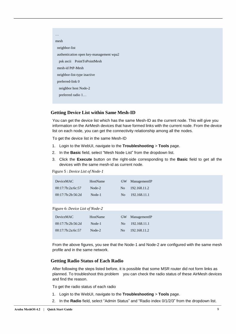
…
mesh
neighbor-list
authentication open key-management wpa2
psk ascii PointToPointMesh
mesh-id PtP-Mesh
neighbor-list-type inactive
preferred-link 0
neighbor host Node-2
preferred radio 1…
10 Copyright 2010 Aruba Networks
3. Click the Execute button on the right-side corresponding to the Radio field to get the Radio #
status on current node.
The same steps should be applied to check the radio status on each radio of these AirMesh
devices.
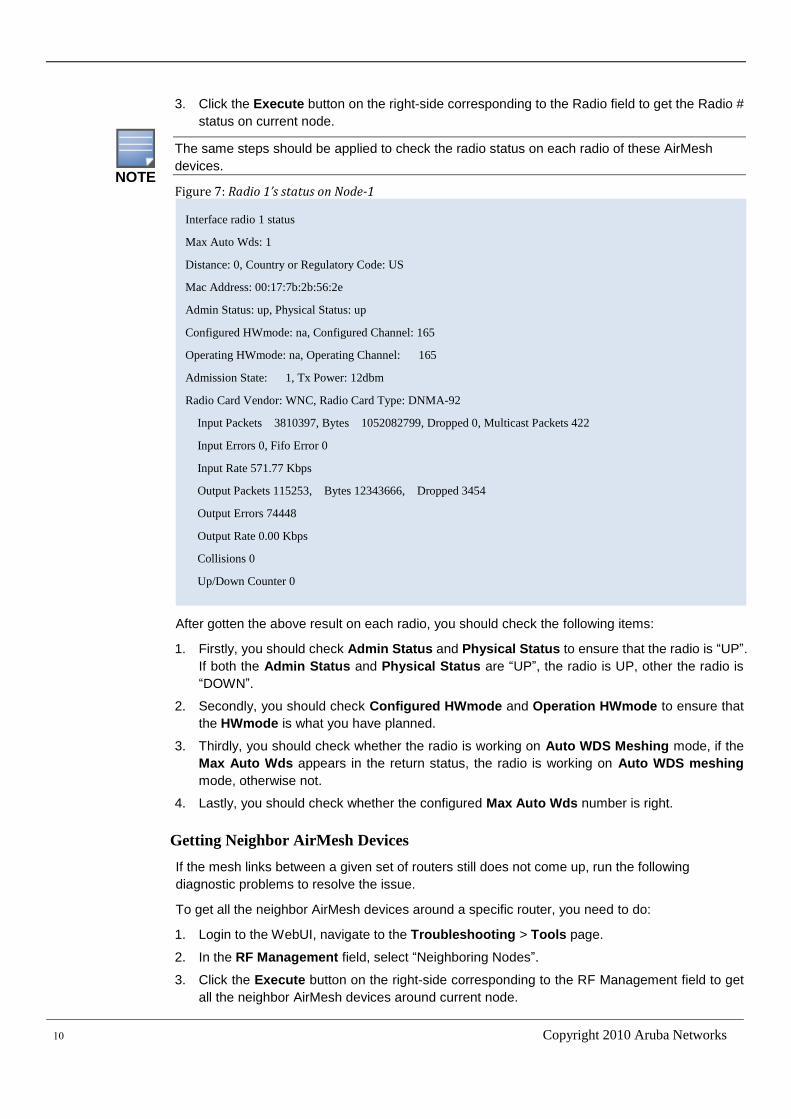
Figure 7: Radio 1’s status on Node-1
After gotten the above result on each radio, you should check the following items:
1. Firstly, you should check Admin Status and Physical Status to ensure that the radio is “UP”.
If both the Admin Status and Physical Status are “UP”, the radio is UP, other the radio is
“DOWN”.
2. Secondly, you should check Configured HWmode and Operation HWmode to ensure that
the HWmode is what you have planned.
3. Thirdly, you should check whether the radio is working on Auto WDS Meshing mode, if the
Max Auto Wds appears in the return status, the radio is working on Auto WDS meshing
mode, otherwise not.
4. Lastly, you should check whether the configured Max Auto Wds number is right.
Getting Neighbor AirMesh Devices
If the mesh links between a given set of routers still does not come up, run the following
diagnostic problems to resolve the issue.
To get all the neighbor AirMesh devices around a specific router, you need to do:
1. Login to the WebUI, navigate to the Troubleshooting > Tools page.
2. In the RF Management field, select “Neighboring Nodes”.
3. Click the Execute button on the right-side corresponding to the RF Management field to get
all the neighbor AirMesh devices around current node.
Interface radio 1 status
Max Auto Wds: 1
Distance: 0, Country or Regulatory Code: US
Mac Address: 00:17:7b:2b:56:2e
Admin Status: up, Physical Status: up
Configured HWmode: na, Configured Channel: 165
Operating HWmode: na, Operating Channel: 165
Admission State: 1, Tx Power: 12dbm
Radio Card Vendor: WNC, Radio Card Type: DNMA-92
Input Packets 3810397, Bytes 1052082799, Dropped 0, Multicast Packets 422
Input Errors 0, Fifo Error 0
Input Rate 571.77 Kbps
Output Packets 115253, Bytes 12343666, Dropped 3454
Output Errors 74448
Output Rate 0.00 Kbps
Collisions 0
Up/Down Counter 0
NOTE
Aruba MeshOS 4.2 | Quick Start Guide 11
4. The result will be displayed at the bottom of the page.
The same steps can be applied to each node to get their neighbor AIrMesh devices
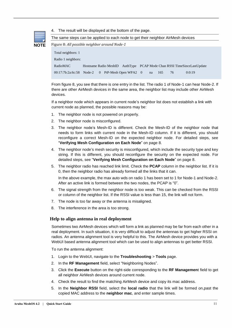
Figure 8: All possible neighbor around Node-1
From figure 8, you see that there is one entry in the list. The radio 1 of Node-1 can hear Node-2. If
there are other AirMesh devices in the same area, the neighbor list may include other AirMesh
devices.
If a neighbor node which appears in current node’s neighbor list does not establish a link with
current node as planned, the possible reasons may be:
1. The neighbor node is not powered on properly.
2. The neighbor node is misconfigured.
3. The neighbor node’s Mesh-ID is different. Check the Mesh-ID of the neighbor node that
needs to form links with current node in the Mesh-ID column. If it is different, you should
reconfigure a correct Mesh-ID on the expected neighbor node. For detailed steps, see
“Verifying Mesh Configuration on Each Node” on page 8.
4. The neighbor node’s mesh security is misconfigured, which include the security type and key
string. If this is different, you should reconfigure the security on the expected node. For
detailed steps, see “Verifying Mesh Configuration on Each Node” on page 8.
5. The neighbor radio has reached link limit. Check the PCAP column in the neighbor list. If it is
0, then the neighbor radio has already formed all the links that it can.
In the above example, the max auto wds on radio 1 has been set to 1 for Node-1 and Node-2.
After an active link is formed between the two nodes, the PCAP is “0”.
6. The signal strength from the neighbor node is too weak. This can be checked from the RSSI
or column of the neighbor list. If the RSSI value is less than 15, the link will not form.
7. The node is too far away or the antenna is misaligned.
8. The interference in the area is too strong.
Help to align antenna in real deployment
Sometimes two AirMesh devices which will form a link as planned may be far from each other in a
real deployment. In such situation, it is very difficult to adjust the antennas to get higher RSSI on
radios. An antenna alignment tool is very helpful to this. The AirMesh device provides you with a
WebUI based antenna alignment tool which can be used to align antennas to get better RSSI.
To run the antenna alignment:
1. Login to the WebUI, navigate to the Troubleshooting > Tools page.
2. In the RF Management field, select “Neighboring Nodes”.
3. Click the Execute button on the right-side corresponding to the RF Management field to get
all neighbor AirMesh devices around current node.
4. Check the result to find the matching AirMesh device and copy its mac address.
5. In the Neighbor RSSI field, select the local radio that the link will be formed on,past the
copied MAC address to the neighbor mac, and enter sample times.
Total neighbors: 1
Radio 1 neighbors:
RadioMAC Hostname Radio MeshID AuthType PCAP Mode Chan RSSI TimeSinceLastUpdate
00:17:7b:2a:6c:58 Node-2 0 PtP-Mesh Open WPA2 0 na 165 76 0:0:19
NOTE
12 Copyright 2010 Aruba Networks
6. Click the Execute button on the right-side corresponding to the Neighbor RSSI field.
7. Current node begins to scan the RSSI of the neighbor radio corresponding to the copied
MAC address, and continuously outputs the scanned RSSI value in the bottom of the page.
8. During scanning, you can adjust the antenna and watch the scanned RSSI. When you get the
highest RSSI on some position, you can stop scanning. This is the best position to align the
antenna.
Building a Four Nodes Mesh Networks
In this section, you will begin to build a larger mesh network with four AirMesh devices. The
topology is shown as below:
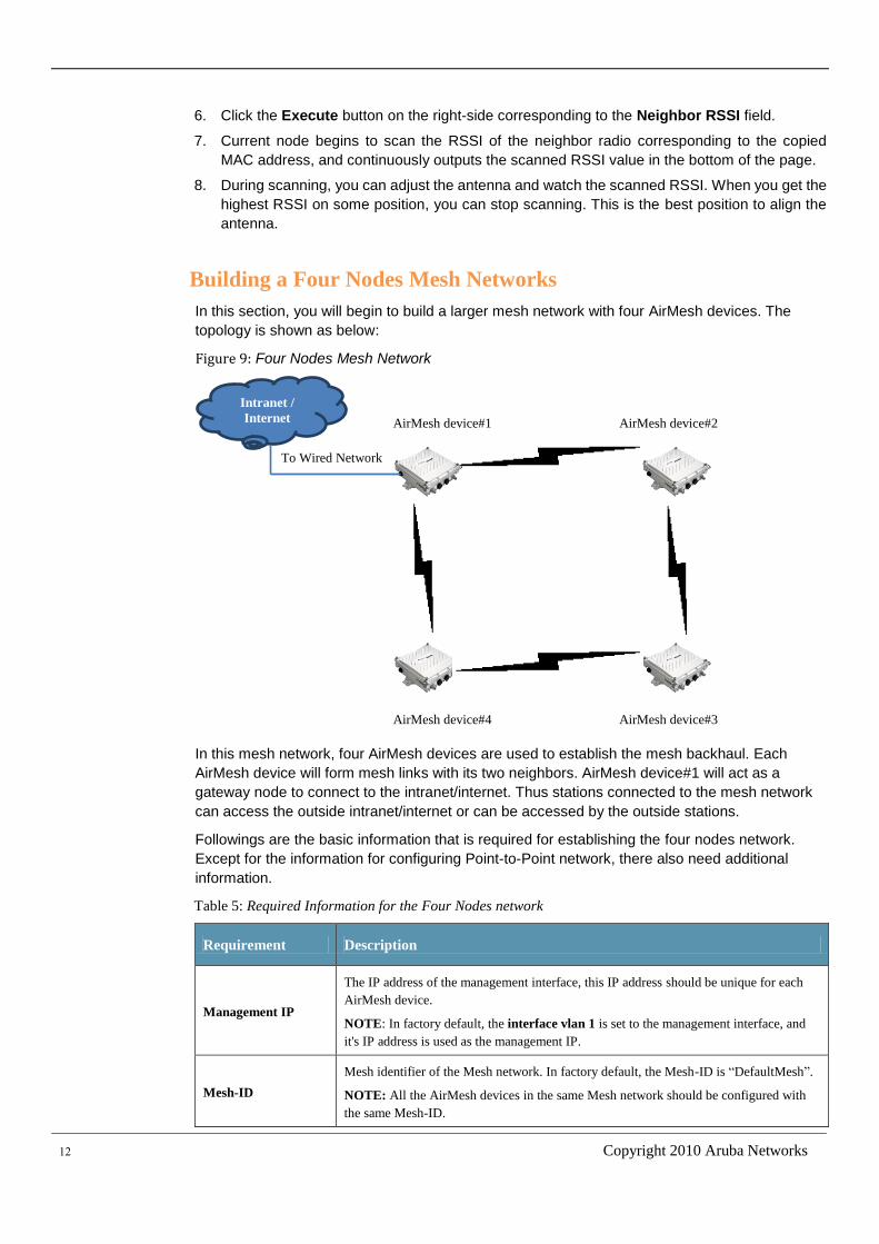
Figure 9: Four Nodes Mesh Network
In this mesh network, four AirMesh devices are used to establish the mesh backhaul. Each
AirMesh device will form mesh links with its two neighbors. AirMesh device#1 will act as a
gateway node to connect to the intranet/internet. Thus stations connected to the mesh network
can access the outside intranet/internet or can be accessed by the outside stations.
Followings are the basic information that is required for establishing the four nodes network.
Except for the information for configuring Point-to-Point network, there also need additional
information.
Table 5: Required Information for the Four Nodes network
Requirement Description
Management IP
The IP address of the management interface, this IP address should be unique for each
AirMesh device.
NOTE: In factory default, the interface vlan 1 is set to the management interface, and
it's IP address is used as the management IP.
Mesh-ID
Mesh identifier of the Mesh network. In factory default, the Mesh-ID is “DefaultMesh”.
NOTE: All the AirMesh devices in the same Mesh network should be configured with
the same Mesh-ID.
Intranet /
Internet AirMesh device#1 AirMesh device#2
AirMesh device#3 AirMesh device#4
To Wired Network
Aruba MeshOS 4.2 | Quick Start Guide 13
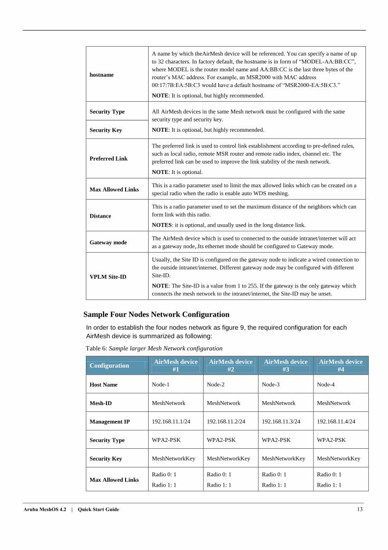
hostname
A name by which theAirMesh device will be referenced. You can specify a name of up
to 32 characters. In factory default, the hostname is in form of “MODEL-AA:BB:CC”,
where MODEL is the router model name and AA:BB:CC is the last three bytes of the
router’s MAC address. For example, an MSR2000 with MAC address
00:17:7B:EA:5B:C3 would have a default hostname of “MSR2000-EA:5B:C3.”
NOTE: It is optional, but highly recommended.
Security Type All AirMesh devices in the same Mesh network must be configured with the same
security type and security key.
NOTE: It is optional, but highly recommended. Security Key
Preferred Link
The preferred link is used to control link establishment according to pre-defined rules,
such as local radio, remote MSR router and remote radio index, channel etc. The
preferred link can be used to improve the link stability of the mesh network.
NOTE: It is optional.
Max Allowed Links This is a radio parameter used to limit the max allowed links which can be created on a
special radio when the radio is enable auto WDS meshing.
Distance
This is a radio parameter used to set the maximum distance of the neighbors which can
form link with this radio.
NOTES: it is optional, and usually used in the long distance link.
Gateway mode The AirMesh device which is used to connected to the outside intranet/internet will act
as a gateway node,.Its ethernet mode should be configured to Gateway mode.
VPLM Site-ID
Usually, the Site ID is configured on the gateway node to indicate a wired connection to
the outside intranet/internet. Different gateway node may be configured with different
Site-ID.
NOTE: The Site-ID is a value from 1 to 255. If the gateway is the only gateway which
connects the mesh network to the intranet/internet, the Site-ID may be unset.
Sample Four Nodes Network Configuration
In order to establish the four nodes network as figure 9, the required configuration for each
AirMesh device is summarized as following:
Table 6: Sample larger Mesh Network configuration
Configuration AirMesh device
#1
AirMesh device
#2
AirMesh device
#3
AirMesh device
#4
Host Name Node-1 Node-2 Node-3 Node-4
Mesh-ID MeshNetwork MeshNetwork MeshNetwork MeshNetwork
Management IP 192.168.11.1/24 192.168.11.2/24 192.168.11.3/24 192.168.11.4/24
Security Type WPA2-PSK WPA2-PSK WPA2-PSK WPA2-PSK
Security Key MeshNetworkKey MeshNetworkKey MeshNetworkKey MeshNetworkKey
Max Allowed Links Radio 0: 1
Radio 1: 1
Radio 0: 1
Radio 1: 1
Radio 0: 1
Radio 1: 1
Radio 0: 1
Radio 1: 1
14 Copyright 2010 Aruba Networks
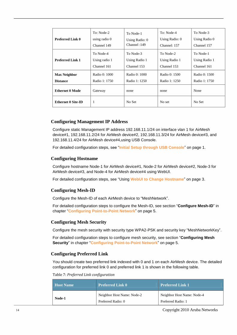
Preferred Link 0
To: Node-2
using radio 0
Channel 149
To Node-1
Using Radio: 0
Channel :149
To: Node-4
Using Radio: 0
Channel: 157
To Node-3
Using Radio 0
Channel 157
Preferred Link 1
To Node-4
Using radio 1
Channel 161
To Node-3
Using Radio 1
Channel 153
To Node-2
Using Radio 1
Channel 153
To Node-1
Using Radio 1
Channel 161
Max Neighbor
Distance
Radio 0: 1000
Radio 1: 1750
Radio 0: 1000
Radio 1: 1250
Radio 0: 1500
Radio 1: 1250
Radio 0: 1500
Radio 1: 1750
Ethernet 0 Mode Gateway none none None
Ethernet 0 Site-ID 1 No Set No set No Set
Configuring Management IP Address
Configure static Management IP address 192.168.11.1/24 on interface vlan 1 for AirMesh
device#1, 192.168.11.2/24 for AirMesh device#2, 192.168.11.3/24 for AirMesh device#3, and
192.168.11.4/24 for AirMesh device#4,using USB Console.
For detailed configuration steps, see “Initial Setup through USB Console” on page 1.
Configuring Hostname
Configure hostname Node-1 for AirMesh device#1, Node-2 for AirMesh device#2, Node-3 for
AirMesh device#3, and Node-4 for AirMesh device#4 using WebUI.
For detailed configuration steps, see “Using WebUI to Change Hostname” on page 3.
Configuring Mesh-ID
Configure the Mesh-ID of each AirMesh device to “MeshNetwork”.
For detailed configuration steps to configure the Mesh-ID, see section “Configure Mesh-ID” in
chapter “Configuring Point-to-Point Network” on page 5.
Configuring Mesh Security
Configure the mesh security with security type WPA2-PSK and security key “MeshNetworkKey”.
For detailed configuration steps to configure mesh security, see section “Configuring Mesh
Security” in chapter “Configuring Point-to-Point Network” on page 5.
Configuring Preferred Link
You should create two preferred link indexed with 0 and 1 on each AirMesh device. The detailed
configuration for preferred link 0 and preferred link 1 is shown in the following table.
Table 7: Preferred Link configuration
Host Name Preferred Link 0 Preferred Link 1
Node-1 Neighbor Host Name: Node-2
Preferred Radio: 0
Neighbor Host Name: Node-4
Preferred Radio: 1
Aruba MeshOS 4.2 | Quick Start Guide 15
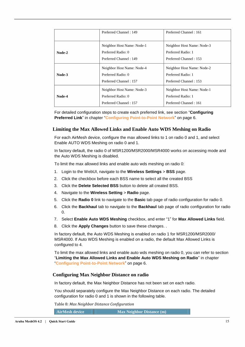
Preferred Channel : 149 Preferred Channel : 161
Node-2
Neighbor Host Name: Node-1
Preferred Radio: 0
Preferred Channel : 149
Neighbor Host Name: Node-3
Preferred Radio: 1
Preferred Channel : 153
Node-3
Neighbor Host Name: Node-4
Preferred Radio: 0
Preferred Channel : 157
Neighbor Host Name: Node-2
Preferred Radio: 1
Preferred Channel : 153
Node-4
Neighbor Host Name: Node-3
Preferred Radio: 0
Preferred Channel : 157
Neighbor Host Name: Node-1
Preferred Radio: 1
Preferred Channel : 161
For detailed configuration steps to create each preferred link, see section “Configuring
Preferred Link” in chapter “Configuring Point-to-Point Network” on page 6.
Limiting the Max Allowed Links and Enable Auto WDS Meshing on Radio
For each AirMesh device, configure the max allowed links to 1 on radio 0 and 1, and select
Enable AUTO WDS Meshing on radio 0 and 1.
In factory default, the radio 0 of MSR1200/MSR2000/MSR4000 works on accessing mode and
the Auto WDS Meshing is disabled.
To limit the max allowed links and enable auto wds meshing on radio 0:
1. Login to the WebUI, navigate to the Wireless Settings > BSS page.
2. Click the checkbox before each BSS name to select all the created BSS
3. Click the Delete Selected BSS button to delete all created BSS.
4. Navigate to the Wireless Setting > Radio page.
5. Click the Radio 0 link to navigate to the Basic tab page of radio configuration for radio 0.
6. Click the Backhaul tab to navigate to the Backhaul tab page of radio configuration for radio
0.
7. Select Enable Auto WDS Meshing checkbox, and enter “1” for Max Allowed Links field.
8. Click the Apply Changes button to save these changes. .
In factory default, the Auto WDS Meshing is enabled on radio 1 for MSR1200/MSR2000/
MSR4000. If Auto WDS Meshing is enabled on a radio, the default Max Allowed Links is
configured to 4.
To limit the max allowed links and enable auto wds meshing on radio 0, you can refer to section
“Limiting the Max Allowed Links and Enable Auto WDS Meshing on Radio” in chapter
“Configuring Point-to-Point Network” on page 6.
Configuring Max Neighbor Distance on radio
In factory default, the Max Neighbor Distance has not been set on each radio.
You should separately configure the Max Neighbor Distance on each radio. The detailed
configuration for radio 0 and 1 is shown in the following table.
Table 8: Max Neighbor Distance Configuration
AirMesh device Max Neighbor Distance (m)
16 Copyright 2010 Aruba Networks
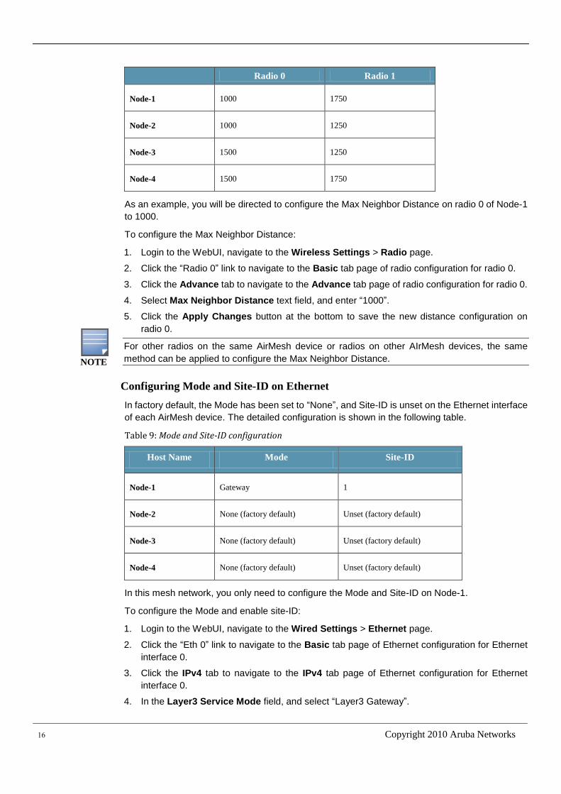
Radio 0 Radio 1
Node-1 1000 1750
Node-2 1000 1250
Node-3 1500 1250
Node-4 1500 1750
As an example, you will be directed to configure the Max Neighbor Distance on radio 0 of Node-1
to 1000.
To configure the Max Neighbor Distance:
1. Login to the WebUI, navigate to the Wireless Settings > Radio page.
2. Click the “Radio 0” link to navigate to the Basic tab page of radio configuration for radio 0.
3. Click the Advance tab to navigate to the Advance tab page of radio configuration for radio 0.
4. Select Max Neighbor Distance text field, and enter “1000”.
5. Click the Apply Changes button at the bottom to save the new distance configuration on
radio 0.
For other radios on the same AirMesh device or radios on other AIrMesh devices, the same
method can be applied to configure the Max Neighbor Distance.
Configuring Mode and Site-ID on Ethernet
In factory default, the Mode has been set to “None”, and Site-ID is unset on the Ethernet interface
of each AirMesh device. The detailed configuration is shown in the following table.
Table 9: Mode and Site-ID configuration
Host Name Mode Site-ID
Node-1 Gateway 1
Node-2 None (factory default) Unset (factory default)
Node-3 None (factory default) Unset (factory default)
Node-4 None (factory default) Unset (factory default)
In this mesh network, you only need to configure the Mode and Site-ID on Node-1.
To configure the Mode and enable site-ID:
1. Login to the WebUI, navigate to the Wired Settings > Ethernet page.
2. Click the “Eth 0” link to navigate to the Basic tab page of Ethernet configuration for Ethernet
interface 0.
3. Click the IPv4 tab to navigate to the IPv4 tab page of Ethernet configuration for Ethernet
interface 0.
4. In the Layer3 Service Mode field, and select “Layer3 Gateway”.
NOTE
Aruba MeshOS 4.2 | Quick Start Guide 17
5. Click the Apply Changes button at the bottom to configure Gateway mode on Ethernet
interface 0.
6. Click the VLAN tab to navigate to the VLAN tab page of Ethernet configuration for Ethernet
interface 0.
7. Select VPLM Site-ID text field, and enter “1”.
8. Click the Apply Changes button at the bottom to configure VPLM Site-ID on Ethernet
interface 0.
Connecting the Mesh Network to Wired Network
Connect the Ethernet port 0 of Node-1 to the wired network.
Validating the Four Nodes Network
After you have followed the above steps to do configuration on each AirMesh device, you should
save the configuration and reboot all the nodes.
Next, you should do some works to verify the links and network connectivity.
Validating the mesh network links
You can use the methods which are described in chapter “Troubleshooting Point-to-Point
Network ” on page 7 to check and verify all the links of the four nodes network.
Validating the network connectivity
You can login each router and validate the network connectivity by using the WebUI.
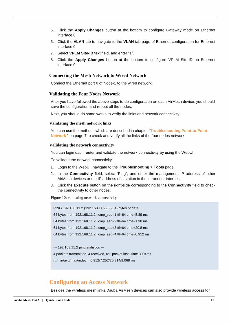
To validate the network connectivity
1. Login to the WebUI, navigate to the Troubleshooting > Tools page.
2. In the Connectivity field, select “Ping”, and enter the management IP address of other
AirMesh devices or the IP address of a station in the intranet or internet.
3. Click the Execute button on the right-side corresponding to the Connectivity field to check
the connectivity to other nodes.
Figure 10: validating network connectivity
Configuring an Access Network
Besides the wireless mesh links, Aruba AirMesh devices can also provide wireless access for
PING 192.168.11.2 (192.168.11.2) 56(84) bytes of data.
64 bytes from 192.168.11.2: icmp_seq=1 ttl=64 time=5.89 ms
64 bytes from 192.168.11.2: icmp_seq=2 ttl=64 time=1.38 ms
64 bytes from 192.168.11.2: icmp_seq=3 ttl=64 time=20.8 ms
64 bytes from 192.168.11.2: icmp_seq=4 ttl=64 time=0.912 ms
--- 192.168.11.2 ping statistics ---
4 packets transmitted, 4 received, 0% packet loss, time 3004ms
rtt min/avg/max/mdev = 0.912/7.252/20.814/8.068 ms
18 Copyright 2010 Aruba Networks
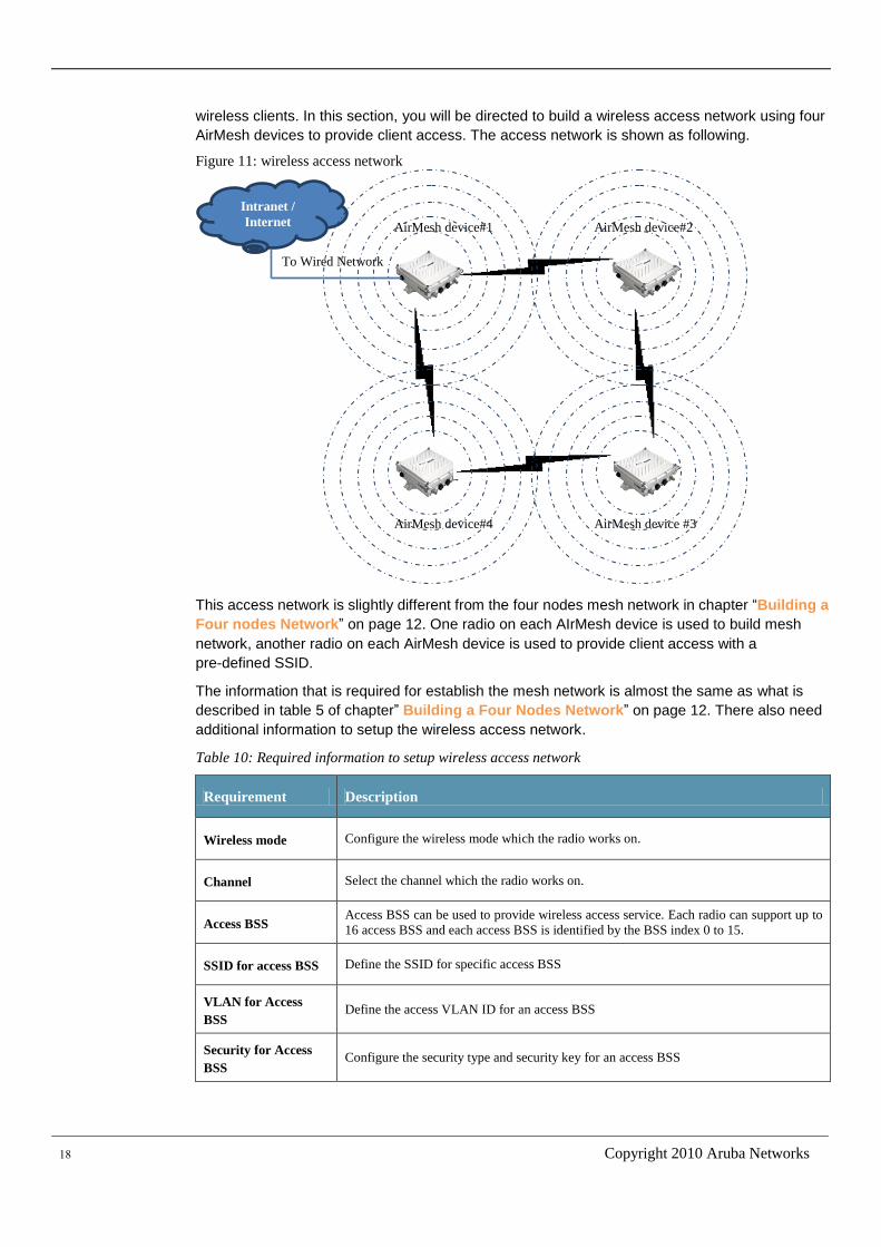
wireless clients. In this section, you will be directed to build a wireless access network using four
AirMesh devices to provide client access. The access network is shown as following.
Figure 11: wireless access network
This access network is slightly different from the four nodes mesh network in chapter “Building a
Four nodes Network” on page 12. One radio on each AIrMesh device is used to build mesh
network, another radio on each AirMesh device is used to provide client access with a
pre-defined SSID.
The information that is required for establish the mesh network is almost the same as what is
described in table 5 of chapter” Building a Four Nodes Network” on page 12. There also need
additional information to setup the wireless access network.
Table 10: Required information to setup wireless access network
Requirement Description
Wireless mode Configure the wireless mode which the radio works on.
Channel Select the channel which the radio works on.
Access BSS Access BSS can be used to provide wireless access service. Each radio can support up to
16 access BSS and each access BSS is identified by the BSS index 0 to 15.
SSID for access BSS Define the SSID for specific access BSS
VLAN for Access
BSS Define the access VLAN ID for an access BSS
Security for Access
BSS Configure the security type and security key for an access BSS
Intranet /
Internet
To Wired Network
AirMesh device#1 AirMesh device#2
AirMesh device #3 AirMesh device#4
Aruba MeshOS 4.2 | Quick Start Guide 19
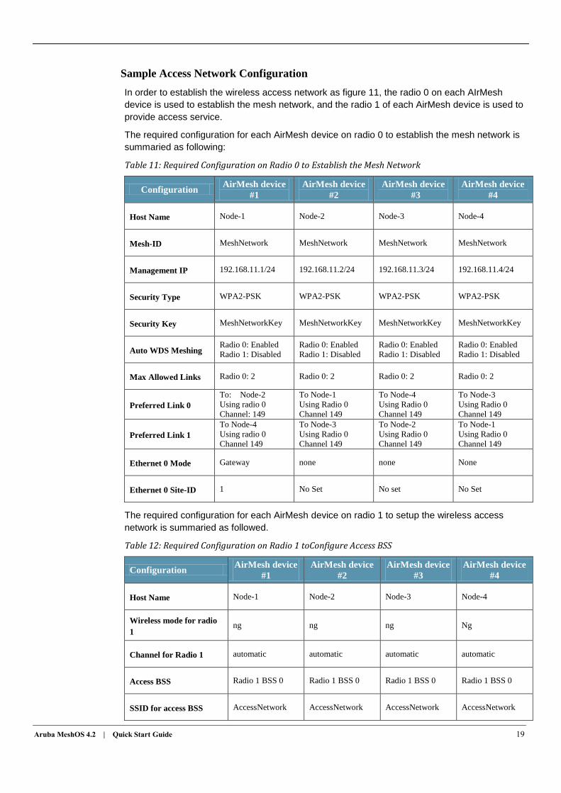
Sample Access Network Configuration
In order to establish the wireless access network as figure 11, the radio 0 on each AIrMesh
device is used to establish the mesh network, and the radio 1 of each AirMesh device is used to
provide access service.
The required configuration for each AirMesh device on radio 0 to establish the mesh network is
summaried as following:
Table 11: Required Configuration on Radio 0 to Establish the Mesh Network
Configuration AirMesh device
#1
AirMesh device
#2
AirMesh device
#3
AirMesh device
#4
Host Name Node-1 Node-2 Node-3 Node-4
Mesh-ID MeshNetwork MeshNetwork MeshNetwork MeshNetwork
Management IP 192.168.11.1/24 192.168.11.2/24 192.168.11.3/24 192.168.11.4/24
Security Type WPA2-PSK WPA2-PSK WPA2-PSK WPA2-PSK
Security Key MeshNetworkKey MeshNetworkKey MeshNetworkKey MeshNetworkKey
Auto WDS Meshing Radio 0: Enabled
Radio 1: Disabled
Radio 0: Enabled
Radio 1: Disabled
Radio 0: Enabled
Radio 1: Disabled
Radio 0: Enabled
Radio 1: Disabled
Max Allowed Links Radio 0: 2 Radio 0: 2 Radio 0: 2 Radio 0: 2
Preferred Link 0
To: Node-2
Using radio 0
Channel: 149
To Node-1
Using Radio 0
Channel 149
To Node-4
Using Radio 0
Channel 149
To Node-3
Using Radio 0
Channel 149
Preferred Link 1
To Node-4
Using radio 0
Channel 149
To Node-3
Using Radio 0
Channel 149
To Node-2
Using Radio 0
Channel 149
To Node-1
Using Radio 0
Channel 149
Ethernet 0 Mode Gateway none none None
Ethernet 0 Site-ID 1 No Set No set No Set
The required configuration for each AirMesh device on radio 1 to setup the wireless access
network is summaried as followed.
Table 12: Required Configuration on Radio 1 toConfigure Access BSS
Configuration AirMesh device
#1
AirMesh device
#2
AirMesh device
#3
AirMesh device
#4
Host Name Node-1 Node-2 Node-3 Node-4
Wireless mode for radio
1 ng ng ng Ng
Channel for Radio 1 automatic automatic automatic automatic
Access BSS Radio 1 BSS 0 Radio 1 BSS 0 Radio 1 BSS 0 Radio 1 BSS 0
SSID for access BSS AccessNetwork AccessNetwork AccessNetwork AccessNetwork
20 Copyright 2010 Aruba Networks
VLAN for Access BSS 1 1 1 1
Security for Access BSS WPA2-PSK
accessnetworkkey
WPA2-PSK
accessnetworkkey
WPA2-PSK
accessnetworkkey
WPA2-PSK
accessnetworkkey
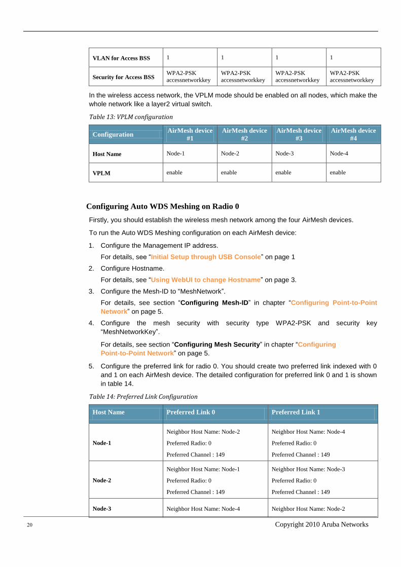
In the wireless access network, the VPLM mode should be enabled on all nodes, which make the
whole network like a layer2 virtual switch.
Table 13: VPLM configuration
Configuration AirMesh device
#1
AirMesh device
#2
AirMesh device
#3
AirMesh device
#4
Host Name Node-1 Node-2 Node-3 Node-4
VPLM enable enable enable enable
Configuring Auto WDS Meshing on Radio 0
Firstly, you should establish the wireless mesh network among the four AirMesh devices.
To run the Auto WDS Meshing configuration on each AirMesh device:
1. Configure the Management IP address.
For details, see “Initial Setup through USB Console” on page 1
2. Configure Hostname.
For details, see “Using WebUI to change Hostname” on page 3.
3. Configure the Mesh-ID to “MeshNetwork”.
For details, see section “Configuring Mesh-ID” in chapter “Configuring Point-to-Point
Network” on page 5.
4. Configure the mesh security with security type WPA2-PSK and security key
“MeshNetworkKey”.
For details, see section “Configuring Mesh Security” in chapter “Configuring
Point-to-Point Network” on page 5.
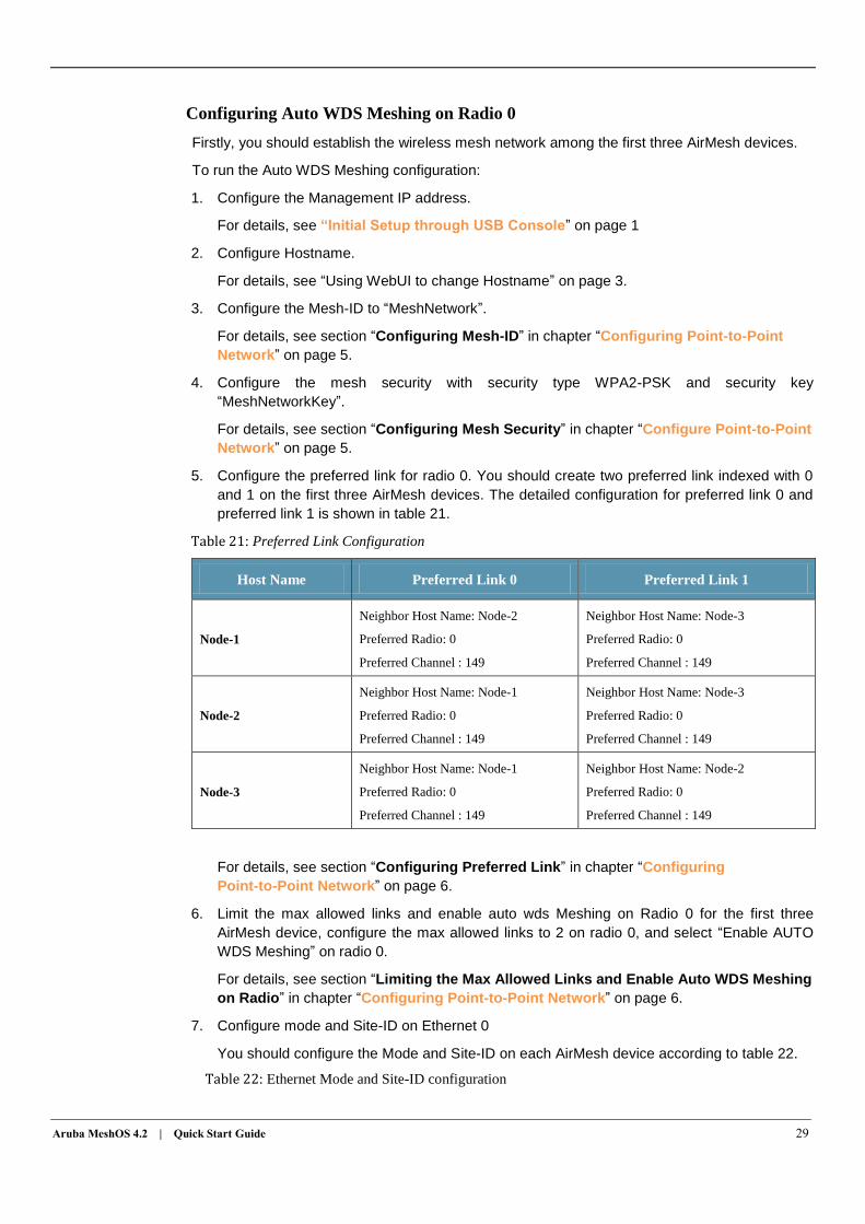
5. Configure the preferred link for radio 0. You should create two preferred link indexed with 0
and 1 on each AirMesh device. The detailed configuration for preferred link 0 and 1 is shown
in table 14.
Table 14: Preferred Link Configuration
Host Name Preferred Link 0 Preferred Link 1
Node-1
Neighbor Host Name: Node-2
Preferred Radio: 0
Preferred Channel : 149
Neighbor Host Name: Node-4
Preferred Radio: 0
Preferred Channel : 149
Node-2
Neighbor Host Name: Node-1
Preferred Radio: 0
Preferred Channel : 149
Neighbor Host Name: Node-3
Preferred Radio: 0
Preferred Channel : 149
Node-3 Neighbor Host Name: Node-4 Neighbor Host Name: Node-2
Aruba MeshOS 4.2 | Quick Start Guide 21
Preferred Radio: 0
Preferred Channel : 149
Preferred Radio: 0
Preferred Channel : 149
Node-4
Neighbor Host Name: Node-3
Preferred Radio: 0
Preferred Channel : 149
Neighbor Host Name: Node-1
Preferred Radio: 0
Preferred Channel : 149
For details, see section “Configuring Preferred Link” in chapter “Configuring
Point-to-Point Network” on page 6.
6. Limit the max allowed links and enable auto wds meshing on radio 0, For each AirMesh
device, configure the max allowed links to 2 on radio 0, and select “Enable AUTO WDS
Meshing” on radio 0.
For details, see section “Limiting the Max Allowed Links and Enable Auto WDS Meshing
on Radio” in chapter “Configuring Point-to-Point Network” on page 6.
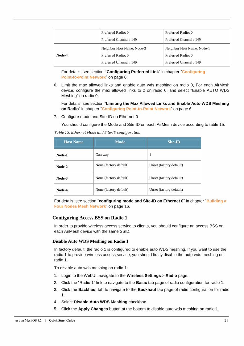
7. Configure mode and Site-ID on Ethernet 0
You should configure the Mode and Site-ID on each AirMesh device according to table 15.
Table 15: Ethernet Mode and Site-ID configuration
Host Name Mode Site-ID
Node-1 Gateway 1
Node-2 None (factory default) Unset (factory default)
Node-3 None (factory default) Unset (factory default)
Node-4 None (factory default) Unset (factory default)
For details, see section “configuring mode and Site-ID on Ethernet 0” in chapter “Building a
Four Nodes Mesh Network” on page 16.
Configuring Access BSS on Radio 1
In order to provide wireless access service to clients, you should configure an access BSS on
each AirMesh device with the same SSID.
Disable Auto WDS Meshing on Radio 1
In factory default, the radio 1 is configured to enable auto WDS meshing. If you want to use the
radio 1 to provide wireless access service, you should firstly disable the auto wds meshing on
radio 1.
To disable auto wds meshing on radio 1:
1. Login to the WebUI, navigate to the Wireless Settings > Radio page.
2. Click the “Radio 1” link to navigate to the Basic tab page of radio configuration for radio 1.
3. Click the Backhaul tab to navigate to the Backhaul tab page of radio configuration for radio
1.
4. Select Disable Auto WDS Meshing checkbox.
5. Click the Apply Changes button at the bottom to disable auto wds meshing on radio 1.
22 Copyright 2010 Aruba Networks
Configuring the Wireless Mode/Channel on Radio 1
In factory default, the radio 1 is working on wireless mode “802.11na 20MHz” and channel 36. In
order to provide wireless access service, you should change the wireless mode to g or ng, and
select a channel.
To configure the wireless mode/channel on radio 1:
1. Login to the WebUI, navigate to the Wireless Settings > Radio page.
2. Click the “Radio 1” link to navigate to the Basic tab page of radio configuration for radio 1.
3. Select “802.11ng 20Mhz” and “1(2.412HHz 20MHzBandwisth)” for Mode/Channel.
4. Click the Apply Changes button at the bottom to save the wireless mode/channel on radio 1.
Configuring Channel Policy on Radio 1
When providing wireless access service to stations, the interference will affect the access
performance. In order to get better access performance, you could configure the channel policy
auto mode to enable the radio to select the best channel to work on.
To configure the wireless mode/channel on radio 1:
1. Login to the WebUI, navigate to the Wireless Settings > Radio page.
2. Click the “Radio 0” link to navigate to the Basic tab page of radio configuration for radio 1.
3. Click the Advance tab to navigate to the Advance tab page of radio configuration for radio 1.
4. In Channel Policy field, select” Auto” to enable automatic channel assignment.
5. Click the Apply Changes button at the bottom to enable automatic channel policy on radio 1.
Creating a New Access BSS on Radio 1 and Set SSID
After the above steps, you have configured the radio specific settings for the access BSS. Next
you should create a new access BSS on specific radio.
Each radio can support up to 16 access BSSes, which are identified by the BSS index 0 to 15. In
the wireless access network of figure 11, a BSS 0 on radio 1 is created for each AirMesh device.
To create a BSS 0 on Radio 1:
1. Login to the WebUI, navigate to the Wireless Settings > BSS page.
2. Click the Create New BSS button to enter create new BSS page,
3. In the BSS name field, select Radio “1” BSS “0”, click Create New BSS button to enter the
Basic page of Configure BSS setting.
4. In the SSID text field, enter “AccessNetwork”.
5. Click the Apply Changes button at the bottom to create the new BSS and set SSID.
Configuring Security for Access BSS
Aruba AirMesh device supports a number of security types to secure access service, which
include Open WEP, Share WEP, WPA-PSK, and WPA2-PSK.
As an example, you will be directed to use WPA2-PSK.
To configure the access BSS security:
1. Login to the WebUI, navigate to the Wireless Settings > BSS page.
2. Select “Radio 1 BSS 0” and click to enter the Basic tab page of configure BSS setting.
3. Click the Security tab to enter the Security tab page of Configure BSS setting, select “WPA2”
for Authentication Type field.
Aruba MeshOS 4.2 | Quick Start Guide 23
4. Select the PSK Key string text field, and enter the key string “AccessNetworkKey”
5. Click the Apply Changes button at the bottom to save the new Security configuration.
For WPA-PSK, the configuration is almost the same as WPA2-PSK. For Open-WEP and Share
WEP, there need extra steps to add the pre-defined WEP keys. For detailed steps, see the
“Configuring BSS interface” chapter in the Aruba Mesh Router Web-based Configuration
Guide.
Configuring Access VLAN for BSS
Setting access VLAN for BSS enables the BSS to work on the layer 2 VLAN mode. When VPLM
is enabled on each AirMesh device, a virtual LAN over the mesh network will connect the access
VLAN for the BSS to the wired network using layer 2 mode.
To configure access vlan 1 for access BSS Radio 1 BSS 0
1. Login to the WebUI, navigate to the Wireless Settings > BSS page.
2. Select “Radio 1 BSS 0” and click to enter the Basic tab page of configure BSS setting.
3. Click the VLAN tab to enter the VLAN tab page of Configure BSS setting, select the access
vlan radio button, and enter “1” in the text field..
4. Click the Apply Changes button at the bottom to apply vlan configuration for the access
BSS.
Enable VPLM mode
The VPLM should be enabled on each AirMesh device, which will enable the whole wireless
mesh network to provide a virtual LAN access to all the stations.
To check VPLM is enabled:
1. Login to the WebUI, navigate to the Service Settings > VPLM page.
2. Check if the status field is Enabled. If status is not enabled, select “Enabled”.
3. Check if the Allowed VLAN is Auto, If Allow VLAN is not Auto, select ”Auto” radio button.
4. If you have changed the configuration of VPLM, click the Apply Changes button at the
bottom to apply new configurations.
Connect the Mesh Network to Wired Network
Connect the Ethernet port 0 of Node-1 to the wired network.
Validating the Wireless Access Network
After you have followed the above steps to do configuration on each AirMesh device, you should
save the configuration and reboot all nodes.
Next, you should do some works to verify the links, VPLM, network connectivity and wireless
access.
Validating the mesh network links
You can use the methods which are described in chapter “Troubleshooting Point-to-Point
Network” on page 7 to check and troubleshoot all the links of wireless access network.
Validating the VPLM Configuration
You can check that the VPLM configuration on each node.
To verify the mesh configuration on a node:
NOTE
24 Copyright 2010 Aruba Networks
1. Login to the WebUI, navigate to the Troubleshooting > Tools page.
2. In the Basic field, select “Running Configuration” from the dropdown list.
3. Click the Execute button on the right-side corresponding to the Basic field to get the running
configuration of the node.
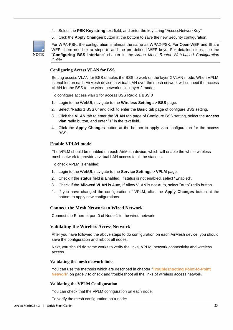
4. The running configuration will be got and displayed on the bottom of the page. In the running
configuration, find VPLM part and verify the configuration as following:
Figure 12: The VPLM configuration
Validating the network connectivity
You can use the WebUI to login each node and validate the network connectivity.
To validate the network connectivity
1. Login to the WebUI, navigate to the Troubleshooting > Tools page.
2. In the Connectivity field, select “Ping”, and enter the management IP address of other MSR
routers or the IP address of a station in the intranet or internet.
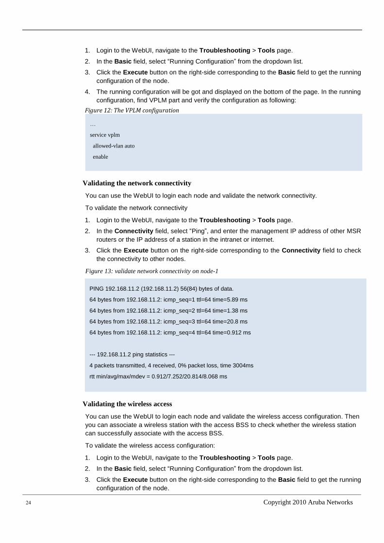
3. Click the Execute button on the right-side corresponding to the Connectivity field to check
the connectivity to other nodes.
Figure 13: validate network connectivity on node-1
Validating the wireless access
You can use the WebUI to login each node and validate the wireless access configuration. Then
you can associate a wireless station with the access BSS to check whether the wireless station
can successfully associate with the access BSS.
To validate the wireless access configuration:
1. Login to the WebUI, navigate to the Troubleshooting > Tools page.
2. In the Basic field, select “Running Configuration” from the dropdown list.
3. Click the Execute button on the right-side corresponding to the Basic field to get the running
configuration of the node.
PING 192.168.11.2 (192.168.11.2) 56(84) bytes of data.
64 bytes from 192.168.11.2: icmp_seq=1 ttl=64 time=5.89 ms
64 bytes from 192.168.11.2: icmp_seq=2 ttl=64 time=1.38 ms
64 bytes from 192.168.11.2: icmp_seq=3 ttl=64 time=20.8 ms
64 bytes from 192.168.11.2: icmp_seq=4 ttl=64 time=0.912 ms
--- 192.168.11.2 ping statistics ---
4 packets transmitted, 4 received, 0% packet loss, time 3004ms
rtt min/avg/max/mdev = 0.912/7.252/20.814/8.068 ms
…
service vplm
allowed-vlan auto
enable
…
Aruba MeshOS 4.2 | Quick Start Guide 25
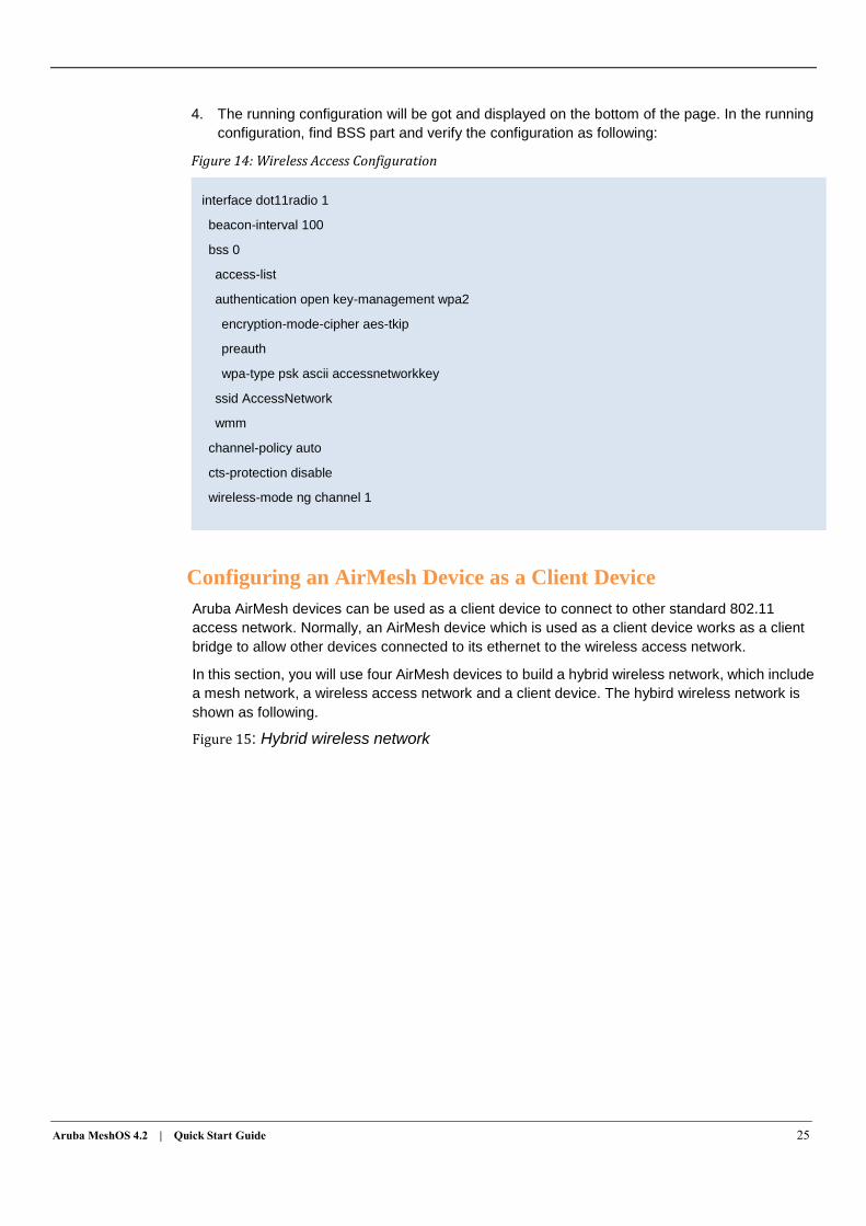
4. The running configuration will be got and displayed on the bottom of the page. In the running
configuration, find BSS part and verify the configuration as following:
Figure 14: Wireless Access Configuration
Configuring an AirMesh Device as a Client Device
Aruba AirMesh devices can be used as a client device to connect to other standard 802.11
access network. Normally, an AirMesh device which is used as a client device works as a client
bridge to allow other devices connected to its ethernet to the wireless access network.
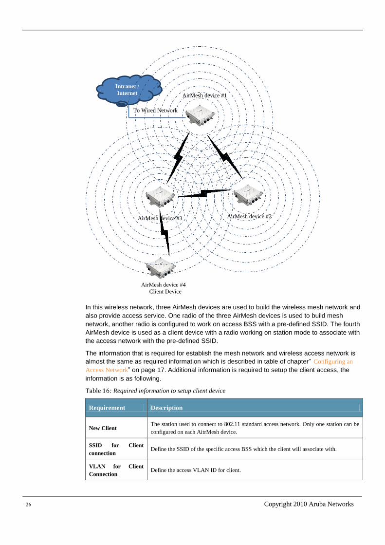
In this section, you will use four AirMesh devices to build a hybrid wireless network, which include
a mesh network, a wireless access network and a client device. The hybird wireless network is
shown as following.
Figure 15: Hybrid wireless network
interface dot11radio 1
beacon-interval 100
bss 0
access-list
authentication open key-management wpa2
encryption-mode-cipher aes-tkip
preauth
wpa-type psk ascii accessnetworkkey
ssid AccessNetwork
wmm
channel-policy auto
cts-protection disable
wireless-mode ng channel 1
26 Copyright 2010 Aruba Networks
In this wireless network, three AirMesh devices are used to build the wireless mesh network and
also provide access service. One radio of the three AirMesh devices is used to build mesh
network, another radio is configured to work on access BSS with a pre-defined SSID. The fourth
AirMesh device is used as a client device with a radio working on station mode to associate with
the access network with the pre-defined SSID.
The information that is required for establish the mesh network and wireless access network is
almost the same as required information which is described in table of chapter” Configuring an
Access Network” on page 17. Additional information is required to setup the client access, the
information is as following.
Table 16: Required information to setup client device
Requirement Description
New Client The station used to connect to 802.11 standard access network. Only one station can be
configured on each AitrMesh device.
SSID for Client
connection Define the SSID of the specific access BSS which the client will associate with.
VLAN for Client
Connection Define the access VLAN ID for client.
Intranet /
Internet
To Wired Network
AirMesh device #1
AirMesh device #2
AirMesh device #4
Client Device
AirMesh device #3
Aruba MeshOS 4.2 | Quick Start Guide 27
Security for Client
Connection Configure the security type and security key for the client.
Ethernet VLAN Define the access VLAN for the Ethernet.
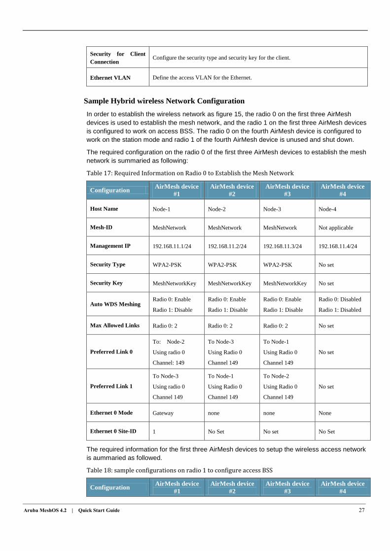
Sample Hybrid wireless Network Configuration
In order to establish the wireless network as figure 15, the radio 0 on the first three AirMesh
devices is used to establish the mesh network, and the radio 1 on the first three AirMesh devices
is configured to work on access BSS. The radio 0 on the fourth AirMesh device is configured to
work on the station mode and radio 1 of the fourth AirMesh device is unused and shut down.
The required configuration on the radio 0 of the first three AirMesh devices to establish the mesh
network is summaried as following:
Table 17: Required Information on Radio 0 to Establish the Mesh Network
Configuration AirMesh device
#1
AirMesh device
#2
AirMesh device
#3
AirMesh device
#4
Host Name Node-1 Node-2 Node-3 Node-4
Mesh-ID MeshNetwork MeshNetwork MeshNetwork Not applicable
Management IP 192.168.11.1/24 192.168.11.2/24 192.168.11.3/24 192.168.11.4/24
Security Type WPA2-PSK WPA2-PSK WPA2-PSK No set
Security Key MeshNetworkKey MeshNetworkKey MeshNetworkKey No set
Auto WDS Meshing Radio 0: Enable
Radio 1: Disable
Radio 0: Enable
Radio 1: Disable
Radio 0: Enable
Radio 1: Disable
Radio 0: Disabled
Radio 1: Disabled
Max Allowed Links Radio 0: 2 Radio 0: 2 Radio 0: 2 No set
Preferred Link 0
To: Node-2
Using radio 0
Channel: 149
To Node-3
Using Radio 0
Channel 149
To Node-1
Using Radio 0
Channel 149
No set
Preferred Link 1
To Node-3
Using radio 0
Channel 149
To Node-1
Using Radio 0
Channel 149
To Node-2
Using Radio 0
Channel 149
No set
Ethernet 0 Mode Gateway none none None
Ethernet 0 Site-ID 1 No Set No set No Set
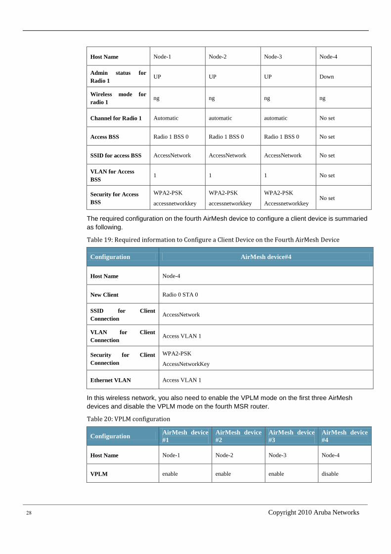
The required information for the first three AirMesh devices to setup the wireless access network
is aummaried as followed.
Table 18: sample configurations on radio 1 to configure access BSS
Configuration AirMesh device
#1
AirMesh device
#2
AirMesh device
#3
AirMesh device
#4
28 Copyright 2010 Aruba Networks
Host Name Node-1 Node-2 Node-3 Node-4
Admin status for
Radio 1 UP UP UP Down
Wireless mode for
radio 1 ng ng ng ng
Channel for Radio 1 Automatic automatic automatic No set
Access BSS Radio 1 BSS 0 Radio 1 BSS 0 Radio 1 BSS 0 No set
SSID for access BSS AccessNetwork AccessNetwork AccessNetwork No set
VLAN for Access
BSS 1 1 1 No set
Security for Access
BSS
WPA2-PSK
accessnetworkkey
WPA2-PSK
accessnetworkkey
WPA2-PSK
Accessnetworkkey No set
The required configuration on the fourth AirMesh device to configure a client device is summaried
as following.
Table 19: Required information to Configure a Client Device on the Fourth AirMesh Device
Configuration AirMesh device#4
Host Name Node-4
New Client Radio 0 STA 0
SSID for Client
Connection AccessNetwork
VLAN for Client
Connection Access VLAN 1
Security for Client
Connection
WPA2-PSK
AccessNetworkKey
Ethernet VLAN Access VLAN 1
In this wireless network, you also need to enable the VPLM mode on the first three AirMesh
devices and disable the VPLM mode on the fourth MSR router.
Table 20: VPLM configuration
Configuration AirMesh device
#1
AirMesh device
#2
AirMesh device
#3
AirMesh device
#4
Host Name Node-1 Node-2 Node-3 Node-4
VPLM enable enable enable disable
Aruba MeshOS 4.2 | Quick Start Guide 29
Configuring Auto WDS Meshing on Radio 0
Firstly, you should establish the wireless mesh network among the first three AirMesh devices.
To run the Auto WDS Meshing configuration:
1. Configure the Management IP address.
For details, see “Initial Setup through USB Console” on page 1
2. Configure Hostname.
For details, see “Using WebUI to change Hostname” on page 3.
3. Configure the Mesh-ID to “MeshNetwork”.
For details, see section “Configuring Mesh-ID” in chapter “Configuring Point-to-Point
Network” on page 5.
4. Configure the mesh security with security type WPA2-PSK and security key
“MeshNetworkKey”.
For details, see section “Configuring Mesh Security” in chapter “Configure Point-to-Point
Network” on page 5.
5. Configure the preferred link for radio 0. You should create two preferred link indexed with 0
and 1 on the first three AirMesh devices. The detailed configuration for preferred link 0 and
preferred link 1 is shown in table 21.
Table 21: Preferred Link Configuration
Host Name Preferred Link 0 Preferred Link 1
Node-1
Neighbor Host Name: Node-2
Preferred Radio: 0
Preferred Channel : 149
Neighbor Host Name: Node-3
Preferred Radio: 0
Preferred Channel : 149
Node-2
Neighbor Host Name: Node-1
Preferred Radio: 0
Preferred Channel : 149
Neighbor Host Name: Node-3
Preferred Radio: 0
Preferred Channel : 149
Node-3
Neighbor Host Name: Node-1
Preferred Radio: 0
Preferred Channel : 149
Neighbor Host Name: Node-2
Preferred Radio: 0
Preferred Channel : 149
For details, see section “Configuring Preferred Link” in chapter “Configuring
Point-to-Point Network” on page 6.
6. Limit the max allowed links and enable auto wds Meshing on Radio 0 for the first three
AirMesh device, configure the max allowed links to 2 on radio 0, and select “Enable AUTO
WDS Meshing” on radio 0.
For details, see section “Limiting the Max Allowed Links and Enable Auto WDS Meshing
on Radio” in chapter “Configuring Point-to-Point Network” on page 6.
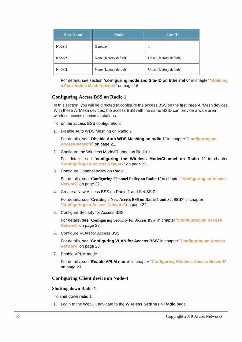
7. Configure mode and Site-ID on Ethernet 0
You should configure the Mode and Site-ID on each AirMesh device according to table 22.
Table 22: Ethernet Mode and Site-ID configuration
30 Copyright 2010 Aruba Networks
Host Name Mode Site-ID
Node-1 Gateway 1
Node-2 None (factory default) Unset (factory default)
Node-3 None (factory default) Unset (factory default)
For details, see section “configuring mode and Site-ID on Ethernet 0” in chapter “Building
a Four Nodes Mesh Network” on page 16.
Configuring Access BSS on Radio 1
In this section, you will be directed to configure the access BSS on the first three AirMesh devices.
With these AirMesh devices, the access BSS with the same SSID can provide a wide area
wireless access service to stations.
To run the access BSS configuration:
1. Disable Auto WDS Meshing on Radio 1
For details, see “Disable Auto WDS Meshing on radio 1” in chapter “Configuring an
Access Network” on page 21.
2. Configure the Wireless Mode/Channel on Radio 1
For details, see “configuring the Wireless Mode/Channel on Radio 1” in chapter
“Configuring an Access Network” on page 22.
3. Configure Channel policy on Radio 1
For details, see “Configuring Channel Policy on Radio 1” in chapter “Configuring an Access
Network” on page 22.
4. Create a New Access BSS on Radio 1 and Set SSID
For details, see “Creating a New Access BSS on Radio 1 and Set SSID” in chapter
“Configuring an Access Network” on page 22.
5. Configure Security for Access BSS
For details, see “Configuring Security for Access BSS” in chapter “Configuring an Access
Network” on page 22.
6. Configure VLAN for Access BSS
For details, see “Configuring VLAN for Access BSS” in chapter “Configuring an Access
Network” on page 23.
7. Enable VPLM mode
For details, see “Enable VPLM mode” in chapter “Configuring Wireless Access Network”
on page 23.
Configuring Client device on Node-4
Shutting down Radio 1
To shut down radio 1:
1. Login to the WebUI, navigate to the Wireless Settings > Radio page.
Aruba MeshOS 4.2 | Quick Start Guide 31
2. Click the “Radio 1” link to navigate to the Basic tab page of radio configuration for radio 1.
3. In the Admin Status field, select Down..
4. Click the Apply Changes button at the bottom to shut down radio 1.
Disable Auto WDS Meshing on Radio 0
In factory default, all the radios are configured to enable auto WDS meshing. If you want to use
the radio 0 to work on station mode, , you should firstly disable the auto WDS meshing on Radio
0.
To disable Auto WDS meshing on radio 0:
1. Login to the WebUI, navigate to the Wireless Settings > Radio page.
2. Click the “Radio 0” link to navigate to the Basic tab page of radio configuration for radio 0.
3. Click the Backhaul tab to navigate to the Backhaul tab page of radio configuration for radio
0.
4. Select Disable Auto WDS Meshing checkbox.
5. Click the Apply Changes button at the bottom to disable auto wds meshing on radio 0.
Deleting all Access BSS configuration on Radio 0
Before you configure the client mode on radio 0, you should clean all BSS configuration on Radio
0.
To delete all the access BSS on Radio 0:
1. Login to the WebUI, navigate to the Wireless Settings > BSS page.
2. Click the checkbox before each BSS name to select all the created BSS
3. Click the Delete Selected BSS button to delete all created BSS.
Creating a New Client on Radio 0 and setting SSID
To create a STA 0 on Radio 0:
1. Login to the WebUI, navigate to the Wireless Settings > Client Mode page.
2. Click the Create button to enter create client mode connection page,
3. In the STA name field, select Radio “0” STA “0”, click Create button to enter the Basic page
of Configure client mode connection.
4. In the SSID of AP text field, enter “AccessNetwork”.
5. Click the Apply Changes button at the bottom to create the new BSS and set SSID.
Configuring Security for Client
Aruba AirMesh device supports a number of security types to secure client, which include Open
WEP, Share WEP, WPA-PSK, and WPA2-PSK.
As an example, you will be directed to use WPA2-PSK.
To configure the client security:
1. Login to the WebUI, navigate to the Wireless Settings > Client Mode page.
2. Select “Radio 0 STA 0” and click to enter the Basic tab page of configure client mode
connection.
3. Click the Security tab to enter the Security tab page of Configure client mode connection,
select “WPA2” for Authentication Type field.
32 Copyright 2010 Aruba Networks
4. Select the PSK Key string text field, and enter the key string “AccessNetworkKey”
5. Click the Apply Changes button at the bottom to save the new Security configuration.
For WPA-PSK, the configuration is almost the same as WPA2-PSK. For Open-WEP and Share
WEP, there need extra steps to add the pre-defined WEP keys. For detailed steps, see the
“Configuring STA interface” chapter in the Aruba Mesh Router Web-based Configuration Guide.
Configuring VLAN for Client
To configure access vlan 1 for client Radio 0 STA 0
1. Login to the WebUI, navigate to the Wireless Settings > Client Mode page.
2. Select “Radio 0 STA 0” and click to enter the Basic tab page of configure client mode
connection.
3. Click the VLAN tab to enter the VLAN tab page of Configure client mode connection,, select
the “Access vlan” radio button, and enter “1” in the text field..
4. Click the Apply Changes button at the bottom to apply vlan configuration for the client.
Configuring VLAN for Ethernet 0
To configure access vlan 1 on Ethernet 0
1. Login to the WebUI, navigate to the Wired Settings > Ethernet page.
2. Select “Eth0” and click to enter the Basic tab page of configure Ethernet.
3. Click the VLAN tab to enter the VLAN tab page of Configure Ethernet, select the “Access
vlan” radio button, and enter “1” in the text field..
4. Click the Apply Changes button at the bottom to apply vlan configuration for the client.
Disable VPLM mode
When the MSR router running as a client device, you have configured it to work on the VLAN
mode, and the VPLM mode should be disabled.
To disable VPLM:
1. Login to the WebUI, navigate to the Service Settings > VPLM page.
2. Check if the status field is “Disabled”. If status is enabled, select “Disabled”.
3. If you have changed the configuration of VPLM, click the Apply Changes button at the
bottom to apply new configurations.
Connecting the Wireless Network to Wired Network
Connect the Ethernet port 0 of Node-1 to the wired network.
Validating the Wireless Network
After you have followed the above steps to do configuration on each AirMesh device, you should
save the configuration and reboot all nodes.
Next, you should do some works to verify the links, VPLM, network connectivity, wireless access
and client device.
You can refer “Validating the wireless access network” on chapter “Configuring an Access
Network” on page 23 to do validate the links, VPLM network connectivity and wireless access
network.
Next, you should do some works to verify the client device.
NOTE
Aruba MeshOS 4.2 | Quick Start Guide 33
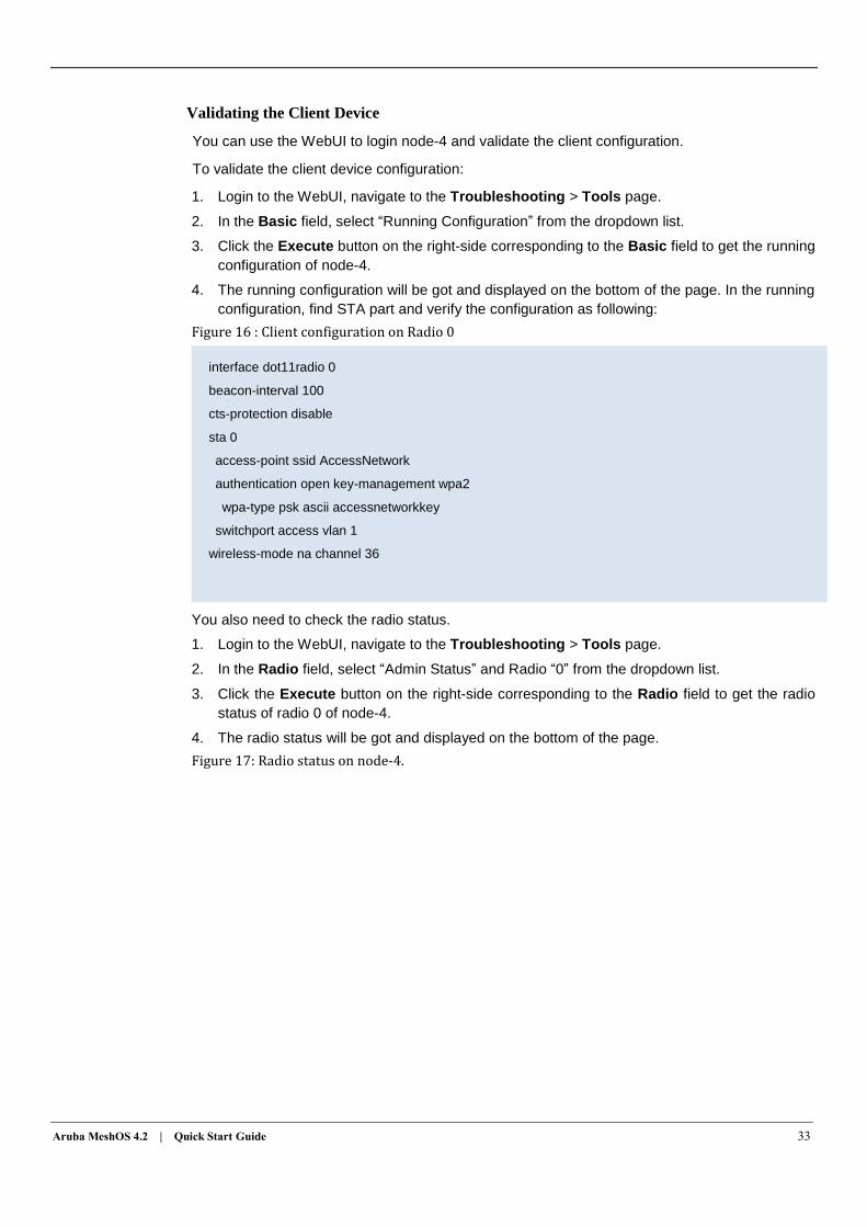
Validating the Client Device
You can use the WebUI to login node-4 and validate the client configuration.
To validate the client device configuration:
1. Login to the WebUI, navigate to the Troubleshooting > Tools page.
2. In the Basic field, select “Running Configuration” from the dropdown list.
3. Click the Execute button on the right-side corresponding to the Basic field to get the running
configuration of node-4.
4. The running configuration will be got and displayed on the bottom of the page. In the running
configuration, find STA part and verify the configuration as following:
Figure 16 : Client configuration on Radio 0
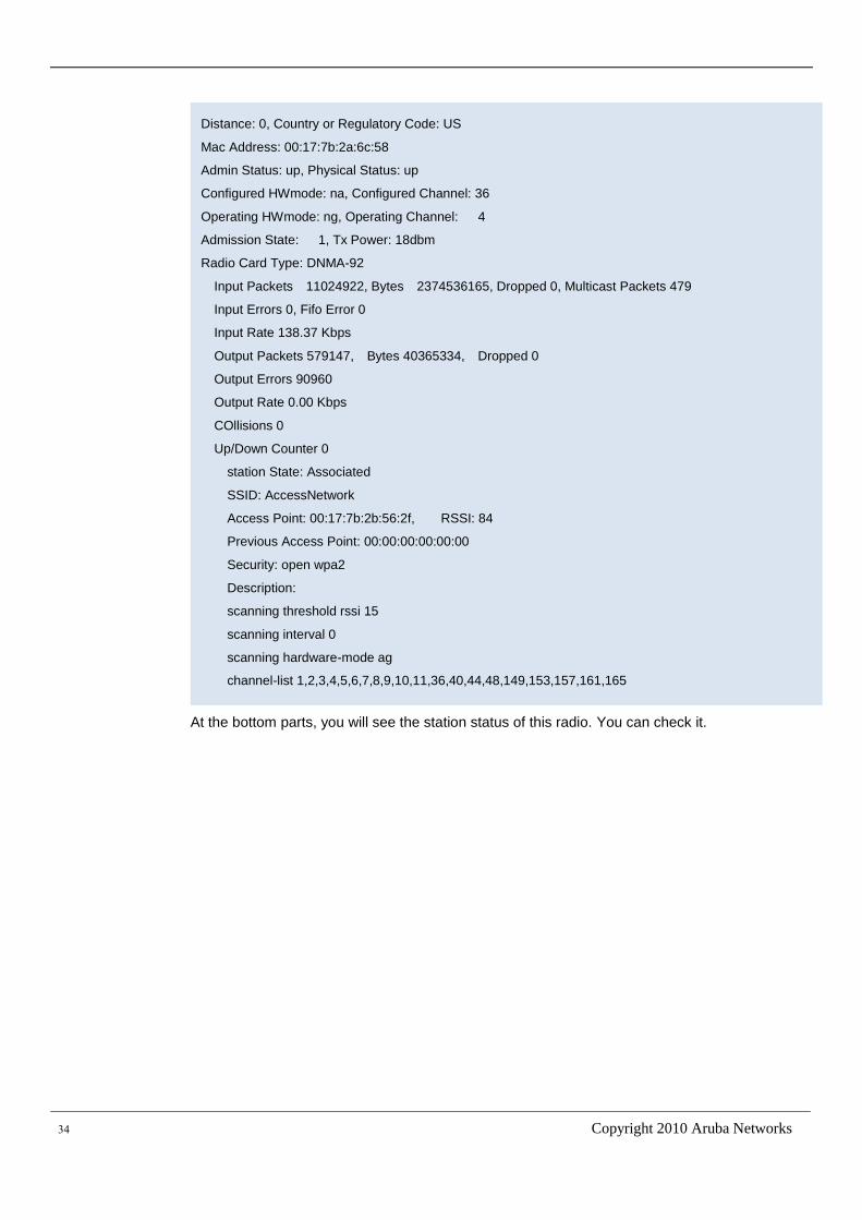
You also need to check the radio status.
1. Login to the WebUI, navigate to the Troubleshooting > Tools page.
2. In the Radio field, select “Admin Status” and Radio “0” from the dropdown list.
3. Click the Execute button on the right-side corresponding to the Radio field to get the radio
status of radio 0 of node-4.
4. The radio status will be got and displayed on the bottom of the page.
Figure 17: Radio status on node-4.
interface dot11radio 0
beacon-interval 100
cts-protection disable
sta 0
access-point ssid AccessNetwork
authentication open key-management wpa2
wpa-type psk ascii accessnetworkkey
switchport access vlan 1
wireless-mode na channel 36
34 Copyright 2010 Aruba Networks
At the bottom parts, you will see the station status of this radio. You can check it.
Distance: 0, Country or Regulatory Code: US
Mac Address: 00:17:7b:2a:6c:58
Admin Status: up, Physical Status: up
Configured HWmode: na, Configured Channel: 36
Operating HWmode: ng, Operating Channel: 4
Admission State: 1, Tx Power: 18dbm
Radio Card Type: DNMA-92
Input Packets 11024922, Bytes 2374536165, Dropped 0, Multicast Packets 479
Input Errors 0, Fifo Error 0
Input Rate 138.37 Kbps
Output Packets 579147, Bytes 40365334, Dropped 0
Output Errors 90960
Output Rate 0.00 Kbps
COllisions 0
Up/Down Counter 0
station State: Associated
SSID: AccessNetwork
Access Point: 00:17:7b:2b:56:2f, RSSI: 84
Previous Access Point: 00:00:00:00:00:00
Security: open wpa2
Description:
scanning threshold rssi 15
scanning interval 0
scanning hardware-mode ag
channel-list 1,2,3,4,5,6,7,8,9,10,11,36,40,44,48,149,153,157,161,165