Embed Size (px)
Citation preview
Authors: Raleigh Littles and Gregory Berberian WRIT 107T (FALL 2015)| HOLMS
ARUBA AP-205H A GUIDE FOR PROFESSIONALS ON HOW TO
INSTALL AND MAINTAIN AN ARUBA AP-205H.
A r u b a 2 0 5 - H I n s t a l l a t i o n G u i d e | 1
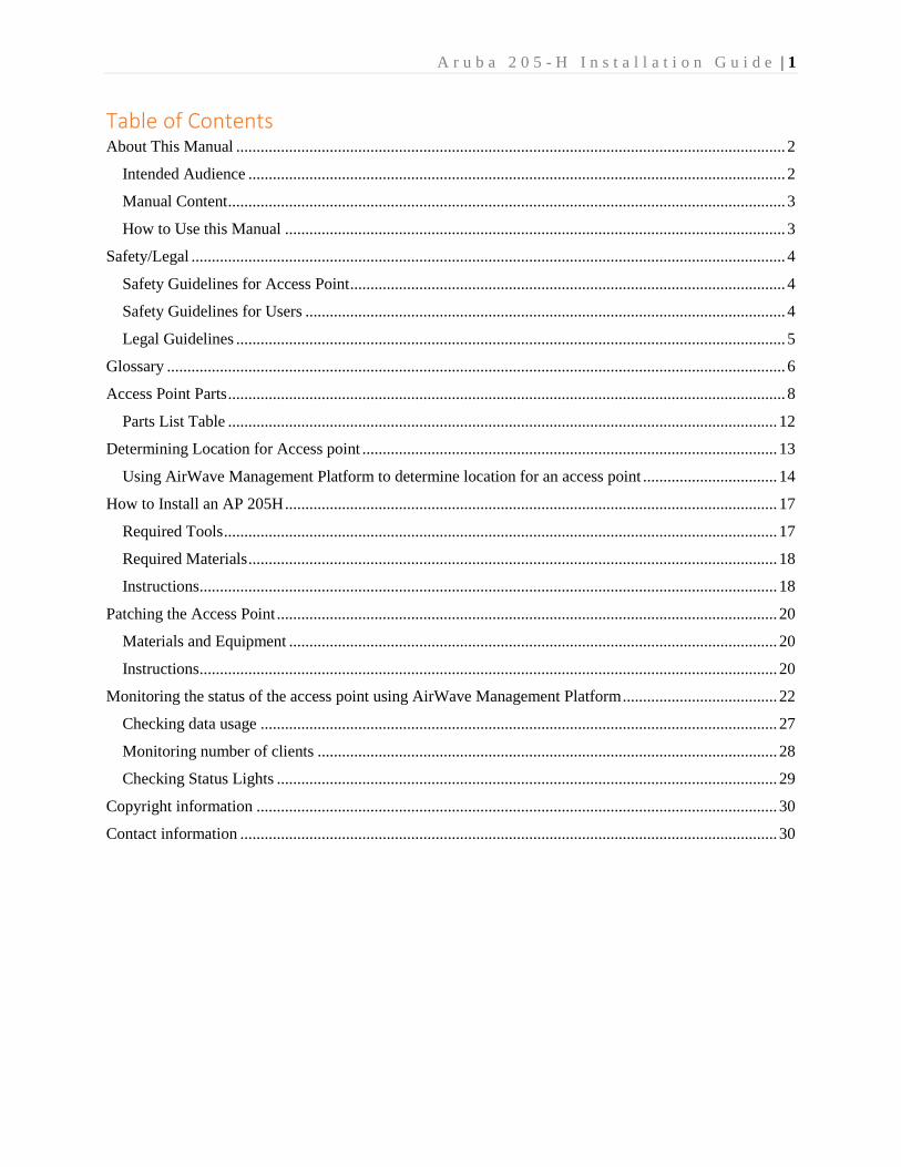
Table of Contents About This Manual ....................................................................................................................................... 2
Intended Audience .................................................................................................................................... 2
Manual Content ......................................................................................................................................... 3
How to Use this Manual ........................................................................................................................... 3
Safety/Legal .................................................................................................................................................. 4
Safety Guidelines for Access Point ........................................................................................................... 4
Safety Guidelines for Users ...................................................................................................................... 4
Legal Guidelines ....................................................................................................................................... 5
Glossary ........................................................................................................................................................ 6
Access Point Parts ......................................................................................................................................... 8
Parts List Table ....................................................................................................................................... 12
Determining Location for Access point ...................................................................................................... 13
Using AirWave Management Platform to determine location for an access point ................................. 14
How to Install an AP 205H ......................................................................................................................... 17
Required Tools ........................................................................................................................................ 17
Required Materials .................................................................................................................................. 18
Instructions .............................................................................................................................................. 18
Patching the Access Point ........................................................................................................................... 20
Materials and Equipment ........................................................................................................................ 20
Instructions .............................................................................................................................................. 20
Monitoring the status of the access point using AirWave Management Platform ...................................... 22
Checking data usage ............................................................................................................................... 27
Monitoring number of clients ................................................................................................................. 28
Checking Status Lights ........................................................................................................................... 29
Copyright information ................................................................................................................................ 30
Contact information .................................................................................................................................... 30
A r u b a 2 0 5 - H I n s t a l l a t i o n G u i d e | 2
About This Manual
This manual is a guide on how to install an Aruba 205-H access point (henceforth referred to as “the
access point”). This document is intended to guide an IT professional throughout all stages of the
installation, as well as through the basics of troubleshooting. This manual will assume that the reader has
a certain amount of experience and knowledge in the field of IT (see Intended Audience).
Intended Audience
This manual is written for people with the following skills:
Basic networking
Familiarity with Windows operating systems
General troubleshooting skills
Familiarity with a web browser such as Chrome or Firefox
Below is a summary the important assumptions we have established. We assume:
The user has sufficient knowledge of the field of IT (see Pre-requisites to using this manual)
The user is using a Windows system (for necessary screenshots).
The installation takes place in the United States (see Safety/Legal).

A r u b a 2 0 5 - H I n s t a l l a t i o n G u i d e | 3
Manual Content
The manual is divided into 9 sections.
How to Use this Manual
There are two ways you can use this document.
1. If you have not followed any of the steps in this manual, please read theit from beginning to end,
in the order given above.
2. If you need to troubleshoot/monitor an access point, you may read only the relevant sections. To
see which sections are intended for troubleshooting/monitoring, please refer to the Table of
Contents.
About this manual
Safety/Legal Glossary
Access point parts
How to install an AP 205H
Patching the access point
Monitoring the status of the access point using AMP
Copyright information
Contact information
A r u b a 2 0 5 - H I n s t a l l a t i o n G u i d e | 4
Safety/Legal
This section discusses safety issues and provides the necessary legal warnings for the installation and use
of the Aruba 205H Access Point.
Safety Guidelines for Access Point
In regards to safety of the access point, please follow the precautions below to ensure that the access point
stays in functional condition:
Do not drop an access point.
Do not subject an access point to extreme weather conditions.
Do not install an access point in an area where it is likely to encounter blunt force trauma from
other users.
Safety Guidelines for Users
In regards to the safety of the user, please follow the instructions below.
Ensure that the batteries (see Gathering necessary tools) for the drill are in good condition. If
they appear swollen or have acid leaking, immediately dispose of them.
If the drill has an off/on switch, always make sure to set it to “off” when not using the drill. This
prevents accidental activation of the drill which could cause bodily harm to the installer.
After the access point has been in use for a while, the back portion may become hot to the touch.
When handling wood screws (see glossary), always grab them by the threading and not the end,
as the ends are sharp and can pierce skin.
A r u b a 2 0 5 - H I n s t a l l a t i o n G u i d e | 5
Legal Guidelines
Before installing, note that in North America only the use of Channels 1-11 is legally permitted by the
Federal Communications Commission (FCC). In addition, note that, as per FCC regulations:
Improper termination of access points installed in the United States will be in violation of the FCC grant
of equipment authorization. Any such willful or intentional violation may result in a requirement by the
FCC for immediate termination of operation and maybe subject forfeiture.
(47 CFR 1.80)
In addition, this device is noted as being compliant with FCC’s radiation exposure limits for Class B
devices. As per FCC regulations, please only install and operate this access point with a minimum of 7.87
inches (20 cm) between the radiator and yourself.
A r u b a 2 0 5 - H I n s t a l l a t i o n G u i d e | 6
Glossary
Below is a glossary for the terms presented in the manual. These are not comprehensive and rigorous
definitions, but are only basic definitions to provide the reader with a working knowledge of the items.
AMP (Air Wave Management Platform): an online software used to manage access points on an
enterprise network.
Crimping: Crimping replaces an RJ-45 connector at the end of an Ethernet cable.
Ethernet: a family of standardized network technologies for wired networks.
Internet: the global intercommunicated networks that is a result of standardized communication
protocols.
Mounting plate/bracket: the plate that helps affix the access point to the wall.
RJ-45 connector: the name for the ‘male’ end of Ethernet cables.
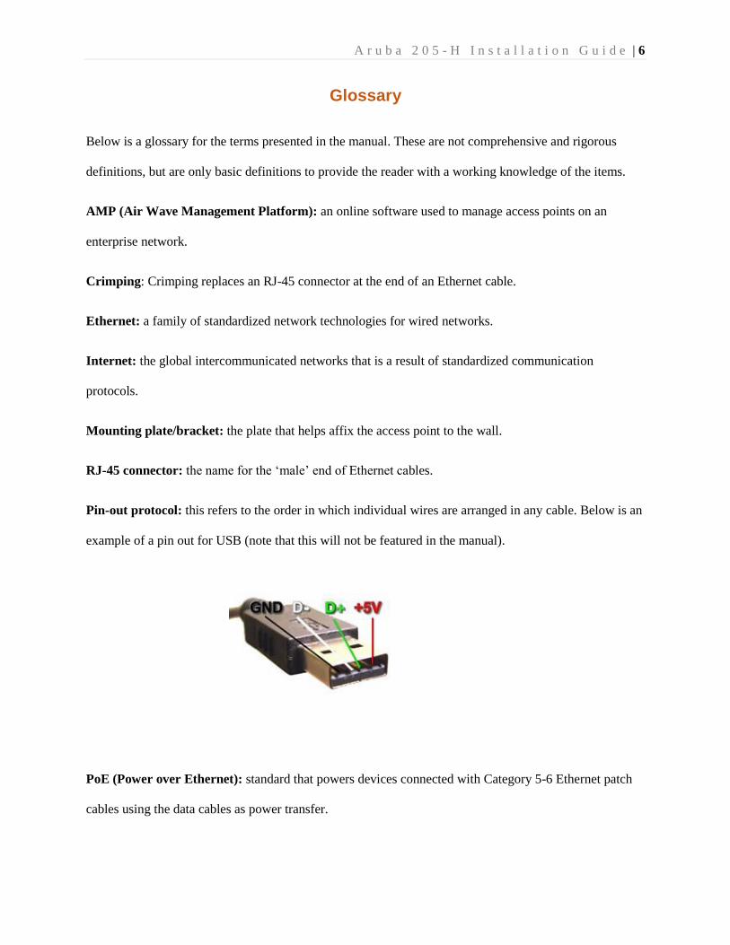
Pin-out protocol: this refers to the order in which individual wires are arranged in any cable. Below is an
example of a pin out for USB (note that this will not be featured in the manual).
PoE (Power over Ethernet): standard that powers devices connected with Category 5-6 Ethernet patch
cables using the data cables as power transfer.
A r u b a 2 0 5 - H I n s t a l l a t i o n G u i d e | 7
Port-mappings: this refers to the use of various ports for connections in IT. Typically, ‘Enet0’
(sometimes abbreviated E0) is used for ethernet connections, whereas ‘data1’ or ‘data2’ is used for voice
connections.
Punch-block: the name for the ‘female’ end of the RJ-45 family that is used in Ethernet cables.
Punching: an operation that replaces the punch-block at the end of an Ethernet cable.
Switch: piece of networking hardware used as a central hub that provides the data for the access points,
as well as being a wired host for other devices. Underground fiber (in a fiber optic network) is fed to a
switch.
Wood screws: this refers to a type of screw that is able to drill into woods and walls. These are
distinguished from machine screws in that their edge is pointed.
A r u b a 2 0 5 - H I n s t a l l a t i o n G u i d e | 8
Access Point Parts
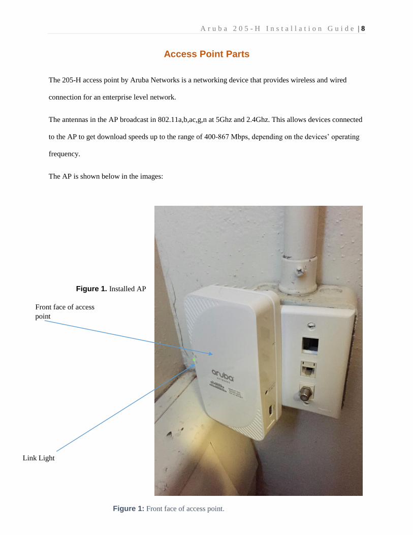
The 205-H access point by Aruba Networks is a networking device that provides wireless and wired
connection for an enterprise level network.
The antennas in the AP broadcast in 802.11a,b,ac,g,n at 5Ghz and 2.4Ghz. This allows devices connected
to the AP to get download speeds up to the range of 400-867 Mbps, depending on the devices’ operating
frequency.
The AP is shown below in the images:
Figure 1. Installed AP
Link Light
Front face of access
point
Figure 1: Front face of access point.
A r u b a 2 0 5 - H I n s t a l l a t i o n G u i d e | 9
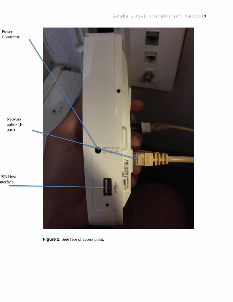
Figure 2. Side face of access point.
Power
Connector
Network
uplink (E0
port)
USB Host
interface
A r u b a 2 0 5 - H I n s t a l l a t i o n G u i d e | 10
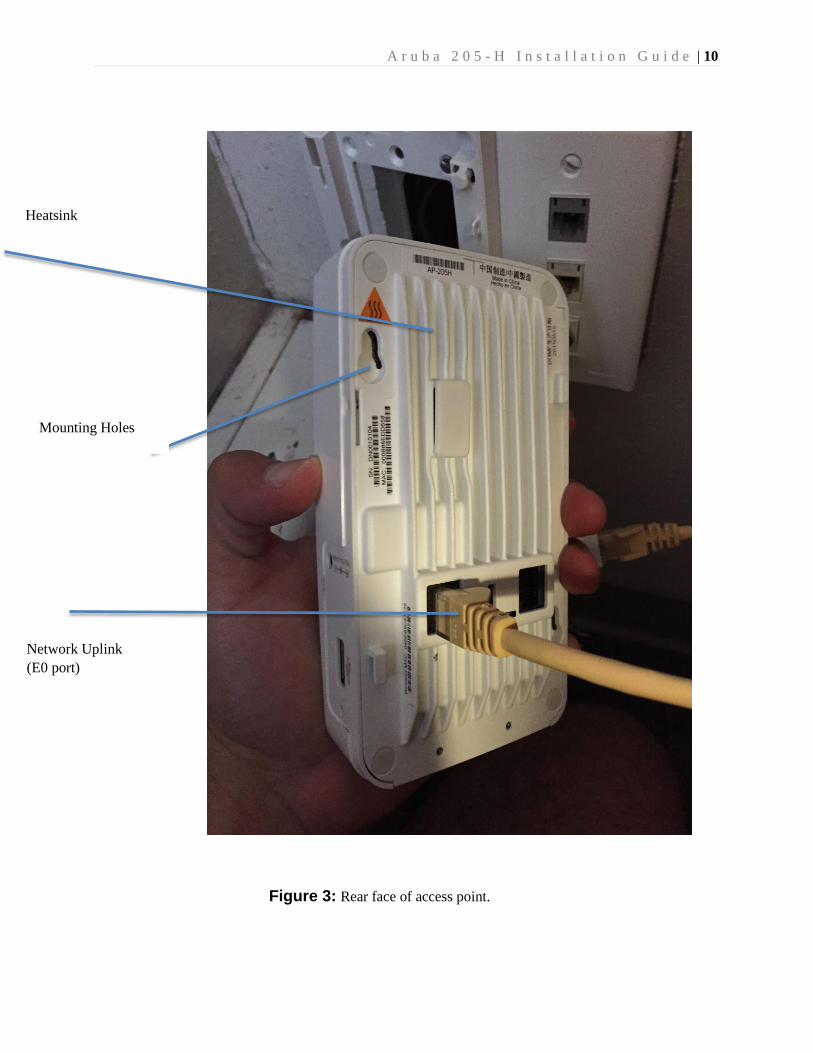
Network Uplink
(E0 port)
Mounting Holes
Heatsink
Figure 3: Rear face of access point.
A r u b a 2 0 5 - H I n s t a l l a t i o n G u i d e | 11
W
i
r
e
d
e
t
h
e
r
n
e
t
p
o
r
t
s
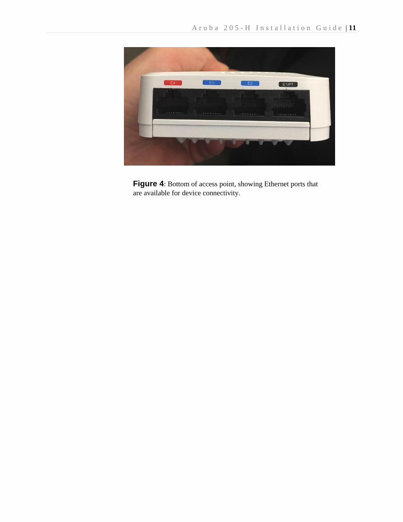
Figure 4: Bottom of access point, showing Ethernet ports that
are available for device connectivity.
A r u b a 2 0 5 - H I n s t a l l a t i o n G u i d e | 12
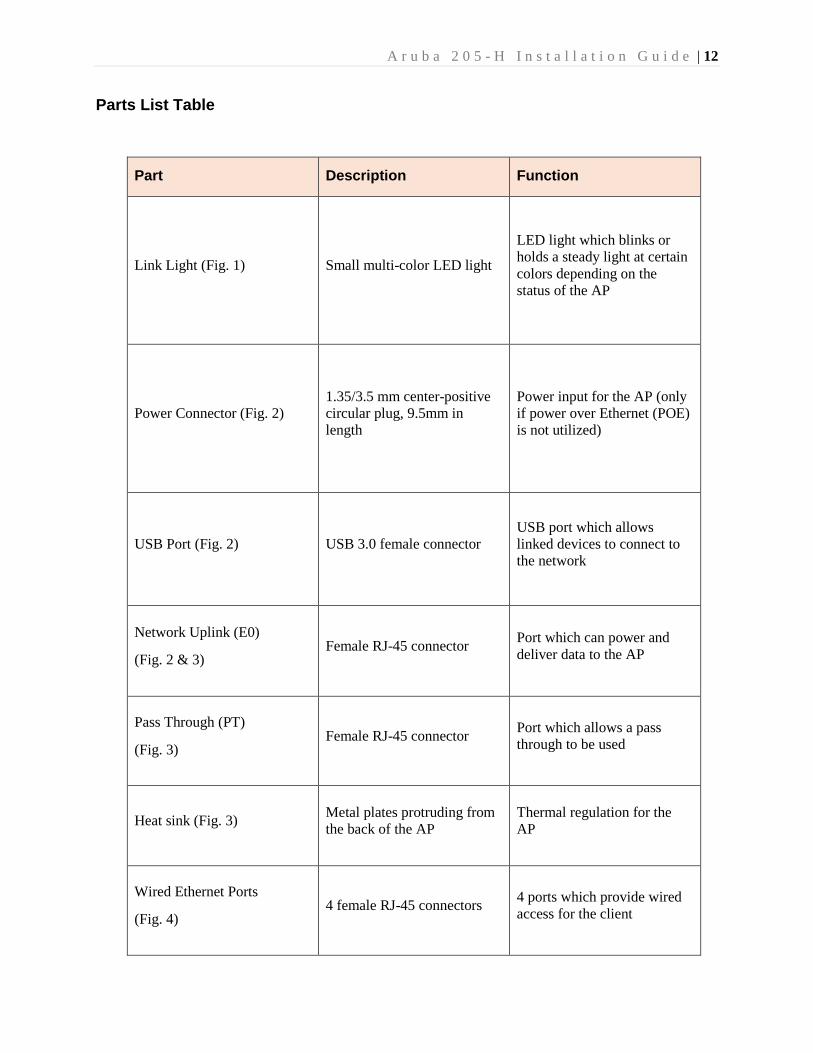
Parts List Table
Part Description Function
Link Light (Fig. 1) Small multi-color LED light
LED light which blinks or
holds a steady light at certain
colors depending on the
status of the AP
Power Connector (Fig. 2)
1.35/3.5 mm center-positive
circular plug, 9.5mm in
length
Power input for the AP (only
if power over Ethernet (POE)
is not utilized)
USB Port (Fig. 2) USB 3.0 female connector
USB port which allows
linked devices to connect to
the network
Network Uplink (E0)
(Fig. 2 & 3) Female RJ-45 connector
Port which can power and
deliver data to the AP
Pass Through (PT)
(Fig. 3) Female RJ-45 connector
Port which allows a pass
through to be used
Heat sink (Fig. 3) Metal plates protruding from
the back of the AP
Thermal regulation for the
AP
Wired Ethernet Ports
(Fig. 4) 4 female RJ-45 connectors
4 ports which provide wired
access for the client
A r u b a 2 0 5 - H I n s t a l l a t i o n G u i d e | 13
Determining Location for Access point
Before installing an access point, we must first determine the location that it will be placed. The following
factors should be considered in determining location for the access point.
Approximate number of devices (clients) that are expected
Proximity to hazards (water, extreme temperatures, etc)
Proximity to devices that emit electromagnetic waves, as this could cause interference.
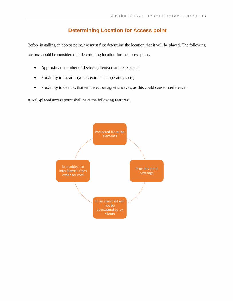
A well-placed access point shall have the following features:
Protected from the elements
Provides good coverage
In an area that will not be
oversaturated by clients
Not subject to interference from
other sources
A r u b a 2 0 5 - H I n s t a l l a t i o n G u i d e | 14
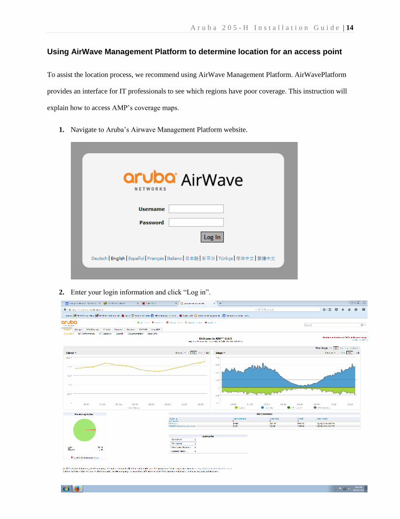
Using AirWave Management Platform to determine location for an access point
To assist the location process, we recommend using AirWave Management Platform. AirWavePlatform
provides an interface for IT professionals to see which regions have poor coverage. This instruction will
explain how to access AMP’s coverage maps.
1. Navigate to Aruba’s Airwave Management Platform website.
2. Enter your login information and click “Log in”.
A r u b a 2 0 5 - H I n s t a l l a t i o n G u i d e | 15
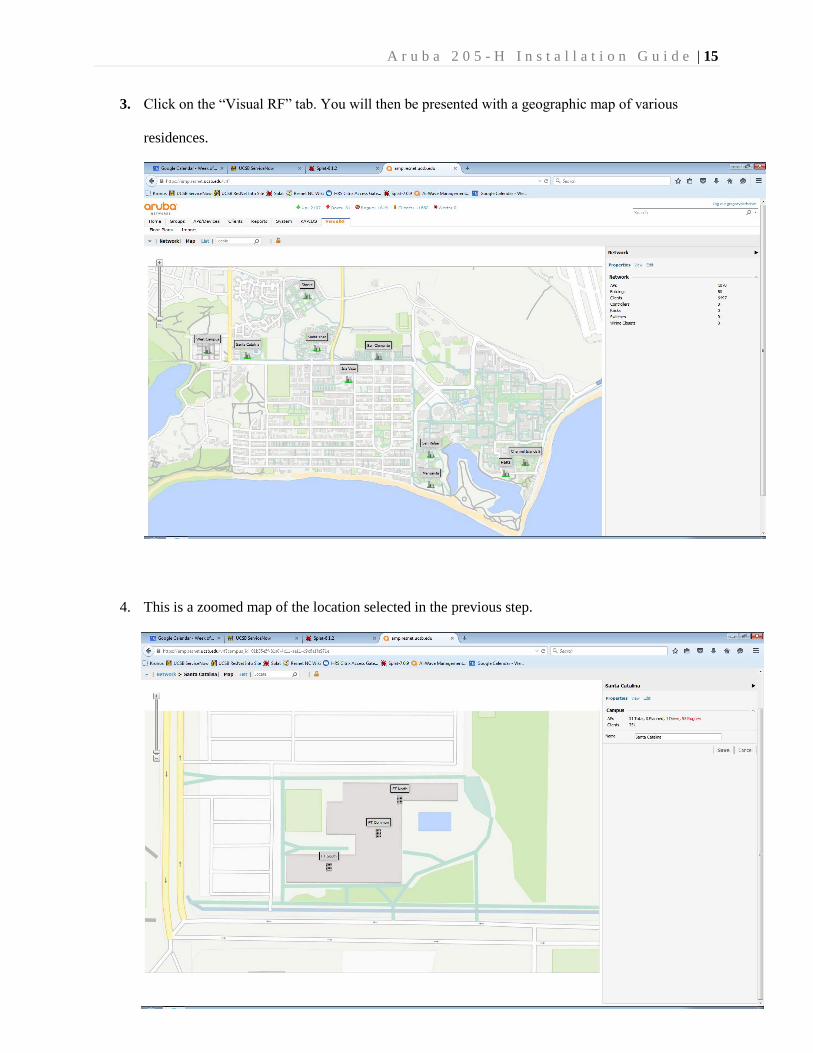
3. Click on the “Visual RF” tab. You will then be presented with a geographic map of various
residences.
4. This is a zoomed map of the location selected in the previous step.
A r u b a 2 0 5 - H I n s t a l l a t i o n G u i d e | 16
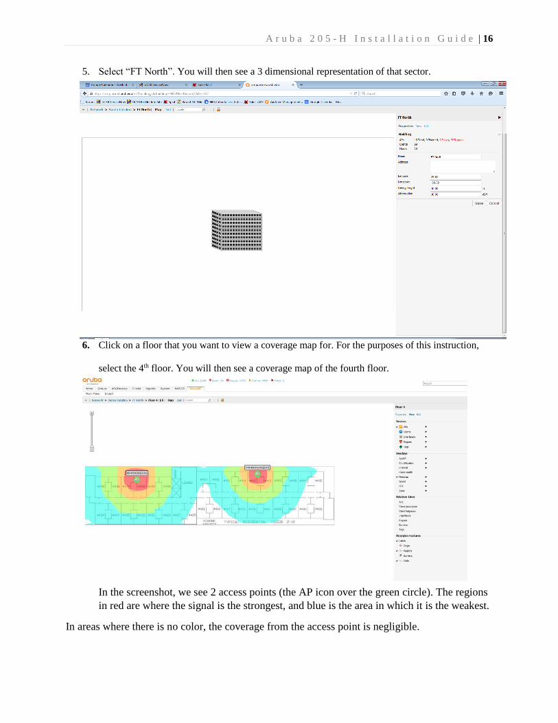
5. Select “FT North”. You will then see a 3 dimensional representation of that sector.
6. Click on a floor that you want to view a coverage map for. For the purposes of this instruction,
select the 4th floor. You will then see a coverage map of the fourth floor.
In the screenshot, we see 2 access points (the AP icon over the green circle). The regions
in red are where the signal is the strongest, and blue is the area in which it is the weakest.
In areas where there is no color, the coverage from the access point is negligible.
A r u b a 2 0 5 - H I n s t a l l a t i o n G u i d e | 17
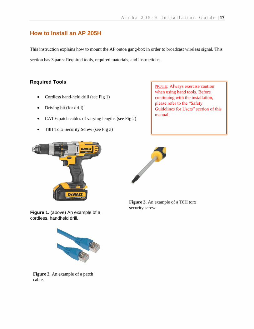
How to Install an AP 205H
This instruction explains how to mount the AP ontoa gang-box in order to broadcast wireless signal. This
section has 3 parts: Required tools, required materials, and instructions.
Required Tools
Cordless hand-held drill (see Fig 1)
Driving bit (for drill)
CAT 6 patch cables of varying lengths (see Fig 2)
T8H Torx Security Screw (see Fig 3)
Figure 1. (above) An example of a
cordless, handheld drill.
Figure 2. An example of a patch
cable.
Figure 3. An example of a T8H torx
security screw.
NOTE: Always exercise caution
when using hand tools. Before
continuing with the installation,
please refer to the “Safety
Guidelines for Users” section of this
manual.
A r u b a 2 0 5 - H I n s t a l l a t i o n G u i d e | 18
Required Materials
AP 205H (in box)
Corded/Cordless Drill
Driving Bit
Torx security screwdriver
Single Gang mounting bracket
2 #6-32 machine screws (in box)
T8H Torx security screw (in box)
6-inch CAT 5e Ethernet patch cable (2 if you plan on using the Pass-through port)
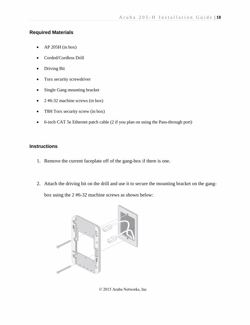
Instructions
1. Remove the current faceplate off of the gang-box if there is one.
2. Attach the driving bit on the drill and use it to secure the mounting bracket on the gang-
box using the 2 #6-32 machine screws as shown below:
© 2015 Aruba Networks, Inc
A r u b a 2 0 5 - H I n s t a l l a t i o n G u i d e | 19
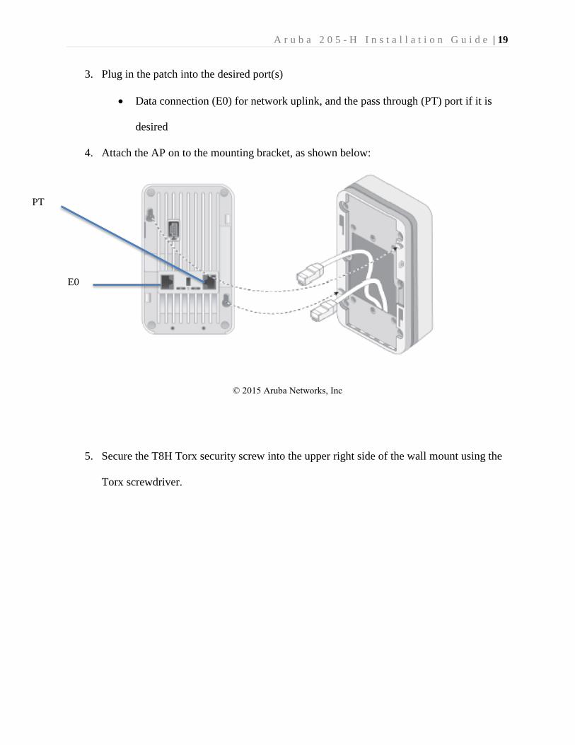
3. Plug in the patch into the desired port(s)
Data connection (E0) for network uplink, and the pass through (PT) port if it is
desired
4. Attach the AP on to the mounting bracket, as shown below:
5. Secure the T8H Torx security screw into the upper right side of the wall mount using the
Torx screwdriver.
E0
PT
© 2015 Aruba Networks, Inc
A r u b a 2 0 5 - H I n s t a l l a t i o n G u i d e | 20
Patching the Access Point
This instruction will guide users on how to patch the access point. If you are unaware of what the
term “patch” means, please refer to the glossary. This instruction is broken into 2 parts:
“Materials and Equipment”, and “Instructions”.
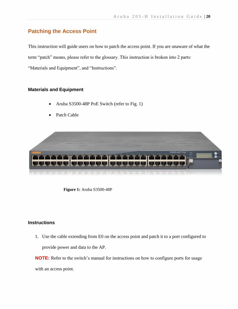
Materials and Equipment
Aruba S3500-48P PoE Switch (refer to Fig. 1)
Patch Cable
Instructions
1. Use the cable extending from E0 on the access point and patch it to a port configured to
provide power and data to the AP.
NOTE: Refer to the switch’s manual for instructions on how to configure ports for usage
with an access point.
Figure 1: Aruba S3500-48P
A r u b a 2 0 5 - H I n s t a l l a t i o n G u i d e | 21
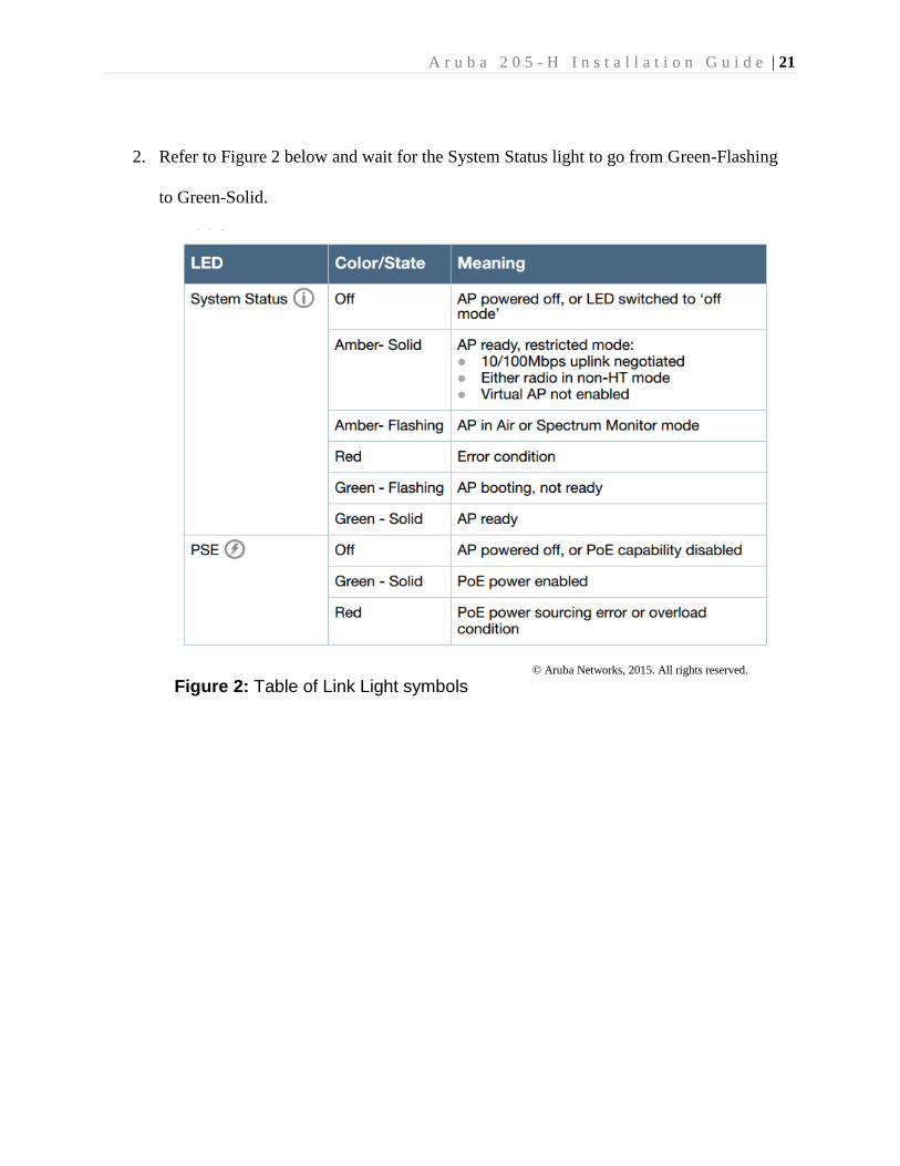
2. Refer to Figure 2 below and wait for the System Status light to go from Green-Flashing
to Green-Solid.
© Aruba Networks, 2015. All rights reserved.
Figure 2: Table of Link Light symbols
A r u b a 2 0 5 - H I n s t a l l a t i o n G u i d e | 22
Monitoring the status of the access point using AirWave Management
Platform
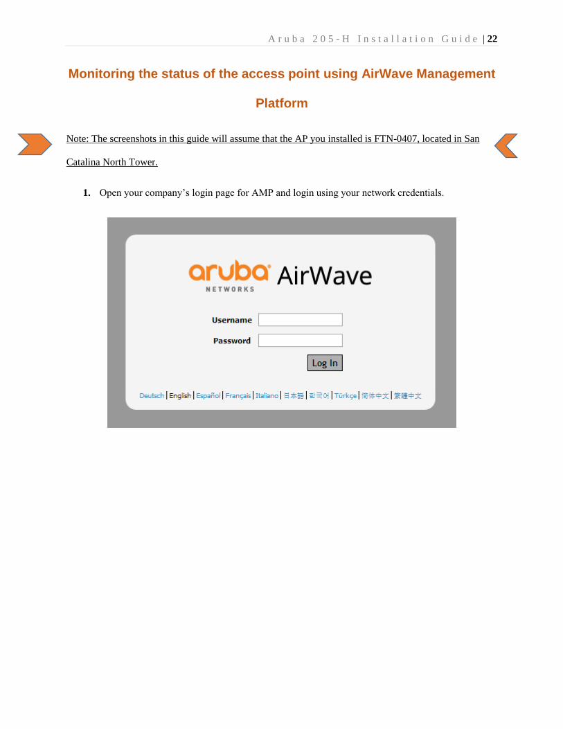
Note: The screenshots in this guide will assume that the AP you installed is FTN-0407, located in San
Catalina North Tower.
1. Open your company’s login page for AMP and login using your network credentials.
A r u b a 2 0 5 - H I n s t a l l a t i o n G u i d e | 23
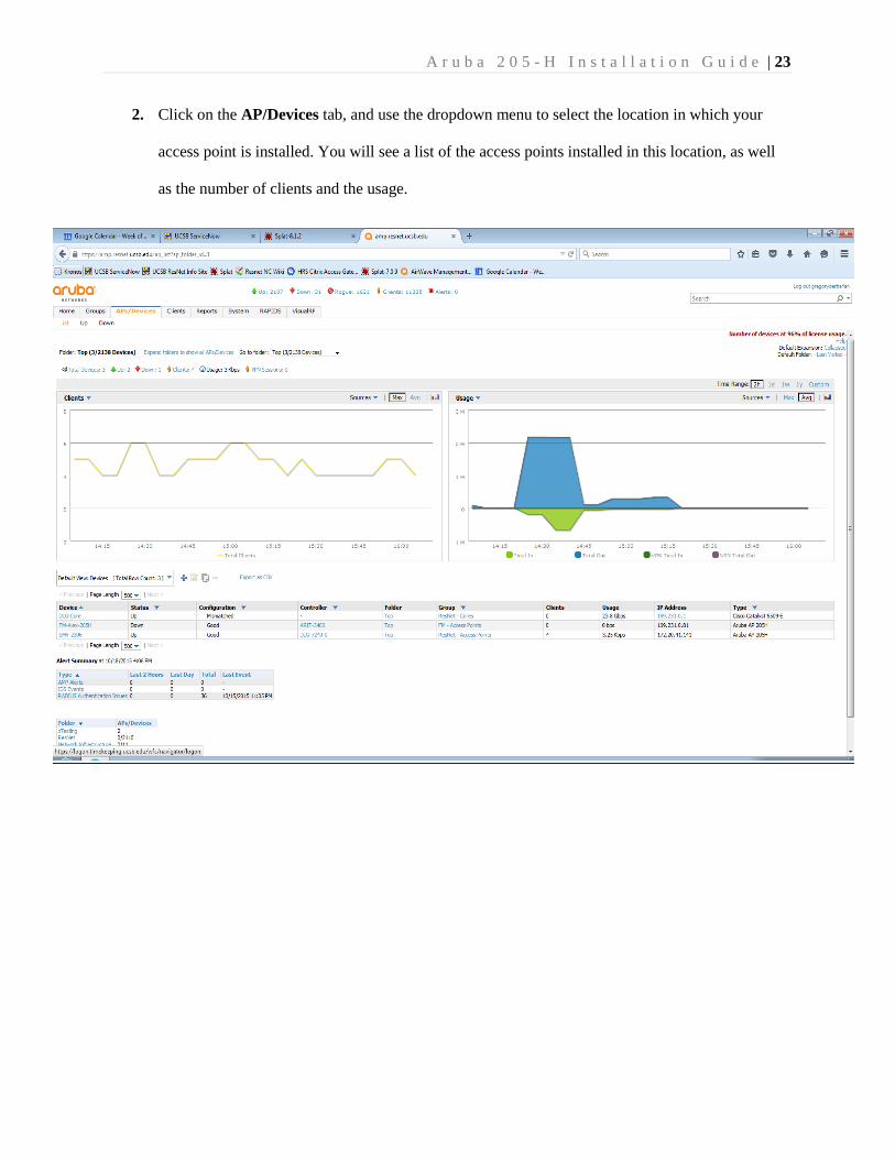
2. Click on the AP/Devices tab, and use the dropdown menu to select the location in which your
access point is installed. You will see a list of the access points installed in this location, as well
as the number of clients and the usage.
A r u b a 2 0 5 - H I n s t a l l a t i o n G u i d e | 24
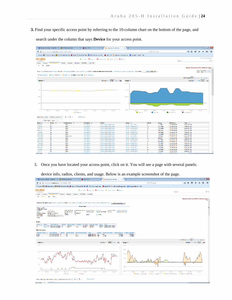
3. Find your specific access point by referring to the 10-column chart on the bottom of the page, and
search under the column that says Device for your access point.
3. Once you have located your access point, click on it. You will see a page with several panels:
device info, radios, clients, and usage. Below is an example screenshot of the page.
A r u b a 2 0 5 - H I n s t a l l a t i o n G u i d e | 25
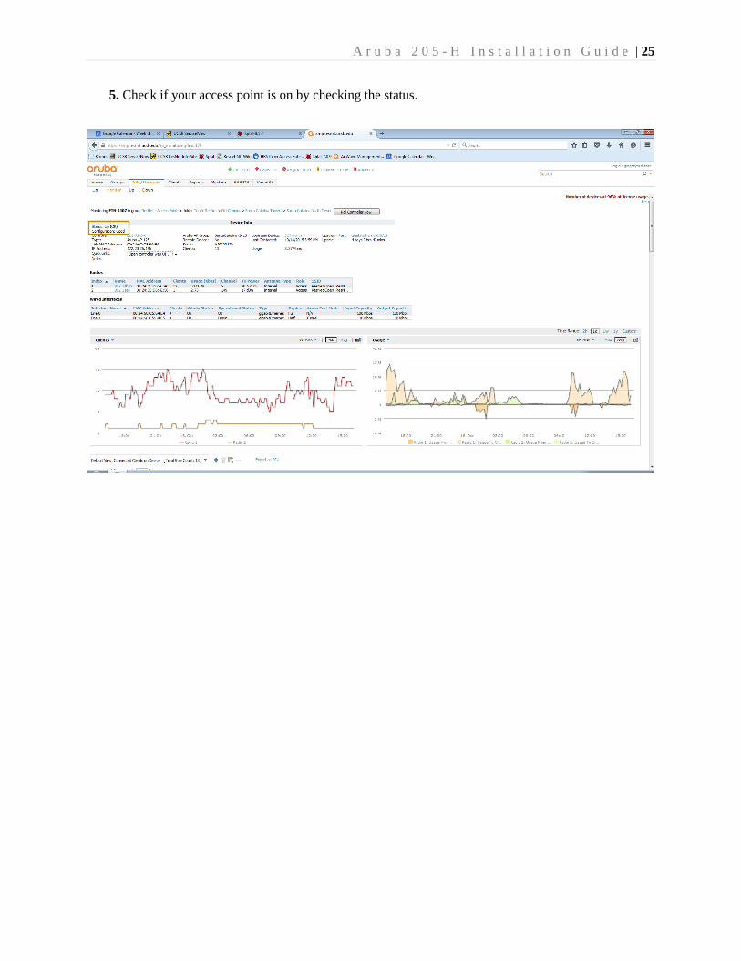
5. Check if your access point is on by checking the status.
A r u b a 2 0 5 - H I n s t a l l a t i o n G u i d e | 26
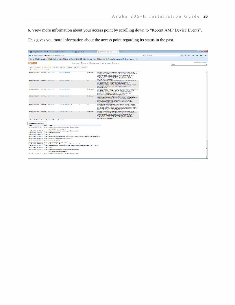
6. View more information about your access point by scrolling down to “Recent AMP Device Events”.
This gives you more information about the access point regarding its status in the past.
A r u b a 2 0 5 - H I n s t a l l a t i o n G u i d e | 27
Checking data usage
One benefit of using Airwave Management Platform is that you can check how much data is being used
on your network. To do so, follow steps 1 through 4 of the Monitoring the status of an access point on
AMP instruction (see page x). Once you have done so, follow the instructions below.
1. You should see the following screen.
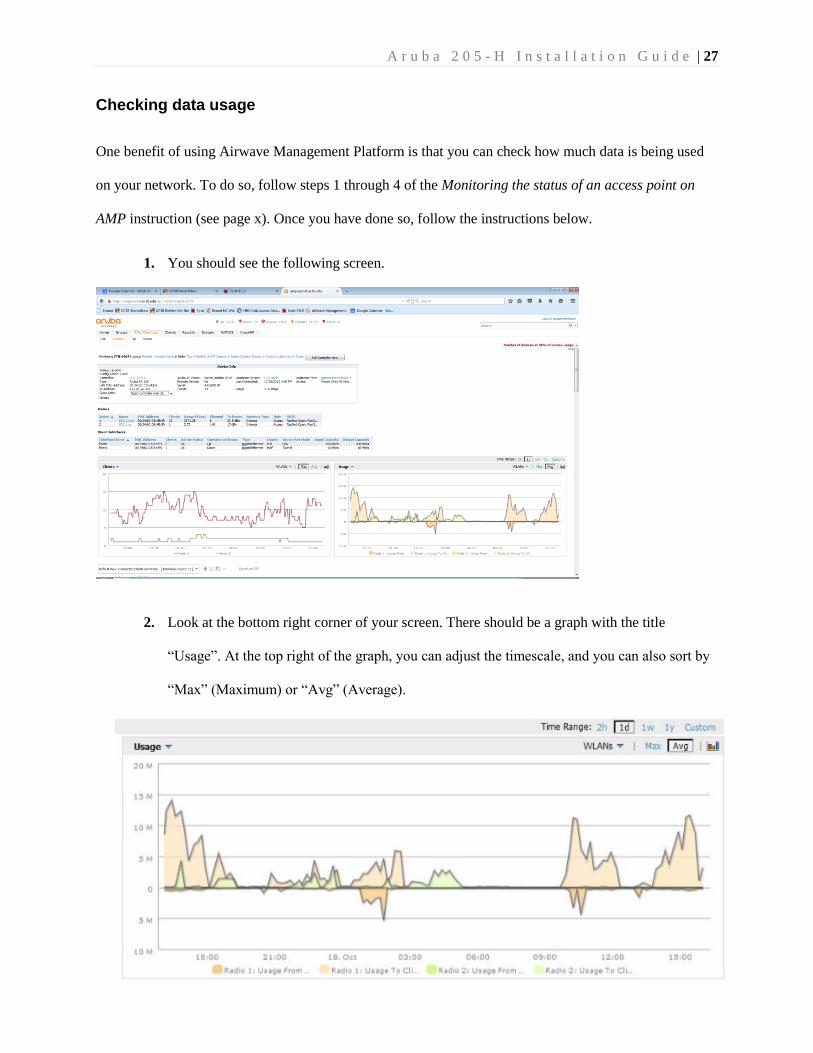
2. Look at the bottom right corner of your screen. There should be a graph with the title
“Usage”. At the top right of the graph, you can adjust the timescale, and you can also sort by
“Max” (Maximum) or “Avg” (Average).
A r u b a 2 0 5 - H I n s t a l l a t i o n G u i d e | 28
Monitoring number of clients
Another helpful feature of AirWave Management platform is the ability to manage the number of clients
(also called devices) that are connected to an access point. Monitoring the number of clients connected to
an access point can help prevent congestion issues. To begin this instruction, please follow steps 1
through 4 of the Monitoring the status of an access point on AMP guide. Once you have done so, continue
reading.
1. You should see the following screen.
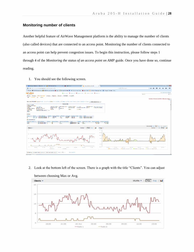
2. Look at the bottom left of the screen. There is a graph with the title “Clients”. You can adjust
between choosing Max or Avg.
A r u b a 2 0 5 - H I n s t a l l a t i o n G u i d e | 29
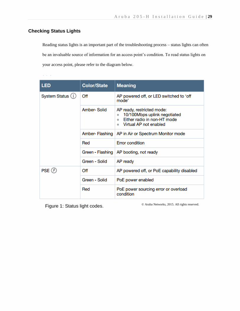
Checking Status Lights
Reading status lights is an important part of the troubleshooting process – status lights can often
be an invaluable source of information for an access point’s condition. To read status lights on
your access point, please refer to the diagram below.
© Aruba Networks, 2015. All rights reserved. Figure 1: Status light codes.
A r u b a 2 0 5 - H I n s t a l l a t i o n G u i d e | 30
Copyright information
No reproduction in any form of this manual, in whole or in part (except for brief quotations in critical
articles or reviews), may be made without express written consent from both authors of this document.
Contact information
For any issues regarding copyright or criticism, please contact both authors, whose contact
information is provided below.
Raleigh Littles
6548 Cordoba Road (34.413899, -119.85549, 6m above sea level)
Goleta CA, 93117
(818) 438-0614
Gregory Berberian
6665 Sueno Road (34.412644, -119.861233, 6m above sea level)
Goleta CA, 93117
(626) 494-1030