Embed Size (px)
Citation preview

Aruba 600 Series Controllers FIPS 140-2 Level 2 Security Policy
Aruba 620 and 650 Mobility
Controllers with ArubaOS FIPS Firmware
Non-Proprietary Security Policy FIPS 140-2 Level 2
Version 3.5 January 2016
2| Aruba 600 Series Controllers FIPS 140-2 Level 2 Security Policy
Copyright
© 2016 Hewlett Packard Enterprise Company. Hewlett Packard Enterprise Company trademarks include , Aruba Networks®, Aruba Wireless Networks®, the registered Aruba the Mobile Edge Company logo, Aruba Mobility Management System®, Mobile Edge Architecture®, People Move. Networks Must Follow®, RFprotectrotect®, Green Island®. All rights reserved. All other trademarks are the property of their respective owners. Open Source Code
Certain Hewlett Packard Enterprise Company products include Open Source software code developed by third parties, including software code subject to the GNU General Public License (GPL), GNU Lesser General Public License (LGPL), or other Open Source Licenses. The Open Source code used can be found at this site:
http://www.arubanetworks.com/open_source
Legal Notice
The use of Aruba. switching platforms and software, by all individuals or corporations, to terminate other vendors’ VPN client devices constitutes complete acceptance of liability by that individual or corporation for this action and indemnifies, in full, Aruba. from any and all legal actions that might be taken against it with respect to infringement of copyright on behalf of those vendors.
Warranty
This hardware product is protected by the standard Aruba warranty of one year parts/labor. For more information, refer to the ARUBACARE SERVICE AND SUPPORT TERMS AND CONDITIONS.
Altering this device (such as painting it) voids the warranty.
Copyright
© 2016 Hewlett Packard Enterprise Company. Hewlett Packard Enterprise Company trademarks include, Aruba Networks®, Aruba Wireless Networks®,the registered Aruba the Mobile Edge Company logo, and Aruba Mobility Management System®.
www.arubanetworks.com 1344 Crossman Avenue Sunnyvale, California 94089 Phone: 408.227.4500 Fax 408.227.4550
Aruba 600 Series Controllers FIPS 140-2 Level 2 Security Policy|3
Contents
Contents ............................................................................................................................................................................. 3
Preface ............................................................................................................................................................................... 5
Purpose of this Document ............................................................................................................................................... 5
Related Documents ......................................................................................................................................................... 5
Additional Product Information ...................................................................................................................... 5
Overview ............................................................................................................................................................................ 6
Cryptographic Module Boundaries ................................................................................................................ 7
Aruba 620 Chassis ........................................................................................................................................ 7
Aruba 650 Chassis ........................................................................................................................................ 9
Intended Level of Security ............................................................................................................................................ 12
Physical Security ............................................................................................................................................................ 13
Operational Environment .............................................................................................................................................. 13
Logical Interfaces ........................................................................................................................................................... 13
Roles and Services ........................................................................................................................................................ 14
Crypto Officer Role ...................................................................................................................................... 14
Authentication Mechanisms ......................................................................................................................... 19
Unauthenticated Services ............................................................................................................................ 20
Non-Approved Services ............................................................................................................................... 20
Cryptographic Key Management ................................................................................................................................. 21
Implemented Algorithms .............................................................................................................................. 21
Non-FIPS Approved Algorithms Allowed in FIPS Mode .............................................................................. 22
Non-FIPS Approved Algorithms .................................................................................................................. 22
Critical Security Parameters ........................................................................................................................ 22
Self-Tests ......................................................................................................................................................................... 27
Alternating Bypass State ............................................................................................................................................... 29
Installing the Controller ........................................................................................................................................................ 30
Pre-Installation Checklist ............................................................................................................................................... 30
Precautions ..................................................................................................................................................................... 30
Product Examination ................................................................................................................................... 31
Package Contents ....................................................................................................................................... 31
Tamper-Evident Labels ................................................................................................................................................. 32
4| Aruba 600 Series Controllers FIPS 140-2 Level 2 Security Policy
Reading TELs .............................................................................................................................................. 32
Required TEL Locations .............................................................................................................................. 33
Aruba 620 .................................................................................................................................................................. 33
Aruba 650 .................................................................................................................................................................. 35
Applying TELs ............................................................................................................................................. 38
Ongoing Management .......................................................................................................................................................... 38
Crypto Officer Management .......................................................................................................................................... 38
User Guidance ................................................................................................................................................................ 38
Setup and Configuration................................................................................................................................................ 39
Setting Up Your Controller ............................................................................................................................................ 39
Enabling FIPS Mode ...................................................................................................................................................... 39
Enabling FIPS Mode with the WebUI .......................................................................................................... 39
Enabling FIPS Mode with the CLI ................................................................................................................ 39
Disallowed FIPS Mode Configurations ....................................................................................................................... 40
Aruba 600 Series Controllers FIPS 140-2 Level 2 Security Policy|5
Preface This security policy document can be copied and distributed freely.
Purpose of this Document This release supplement provides information regarding the Aruba 600 Series Controllers with FIPS 140-2 Level 2 validation from Aruba Networks. The material in this supplement modifies the general Aruba hardware and firmware documentation included with this product and should be kept with your Aruba product documentation.
This supplement primarily covers the non-proprietary Cryptographic Module Security Policy for the Aruba Controller. This security policy describes how the controller meets the security requirements of FIPS 140-2 Level 2 and how to place and maintain the controller in a secure FIPS 140-2 mode. This policy was prepared as part of the FIPS 140-2 Level 2 validation of the product.
FIPS 140-2 (Federal Information Processing Standards Publication 140-2, Security Requirements for Cryptographic Modules) details the U.S. Government requirements for cryptographic modules. More information about the FIPS 140-2 standard and validation program is available on the National Institute of Standards and Technology (NIST) website at:
http://csrc.nist.gov/groups/STM/cmvp/index.html
Related Documents The following items are part of the complete installation and operations documentation included with this product:
Aruba 600 Series Mobility Controller Installation Guide
ArubaOS 6.4 User Guide
ArubaOS 6.4 CLI Reference Guide
ArubaOS 6.4 Quick Start Guide
ArubaOS 6.4 Upgrade Guide
Aruba AP Installation Guides
Additional Product Information
More information is available from the following sources:
The Aruba Networks Web-site contains information on the full line of products from Aruba Networks:
http://www.arubanetworks.com
The NIST Validated Modules Web-site contains contact information for answers to technical or sales-related questions for the product:
http://csrc.nist.gov/groups/STM/cmvp/index.html
6| Aruba 600 Series Controllers FIPS 140-2 Level 2 Security Policy
Overview
The Aruba 600 series Mobility Controllers are network infrastructure devices providing secure, scalable
solutions for enterprise Wi-Fi, network security policy enforcement, VPN services, and wireless intrusion
detection and prevention. Mobility controllers serve as central points of authentication, encryption, access
control, and network coordination for all mobile network services.
The Aruba controller configurations validated during the cryptographic module testing included:
Aruba 620-F1
Aruba 620-USF1
Aruba 650-F1
Aruba 650-USF1
FIPS Kit
o 4011570-01 (Part number for Tamper Evident Labels)
Firmware versions: ArubaOS 6.4.4-FIPS
Note: For radio regulatory reasons, part numbers ending with -USF1 are to be sold in the US only. Part numbers ending with -F1 are considered ‘rest of the world’ and must not be used for deployment in the United States. From a FIPS perspective, both -USF1 and -F1 models are identical and fully FIPS compliant.
Aruba 600 Series Controllers FIPS 140-2 Level 2 Security Policy|7
Physical Description
Cryptographic Module Boundaries
For FIPS 140-2 Level 2 validation, the Mobility Controller has been validated as a multi-chip standalone cryptographic module. The chassis physically encloses the complete set of hardware and firmware components and represents the cryptographic boundary of the switch. The cryptographic boundary is defined as encompassing the top, front, left, right, rear, and bottom surfaces of the case.
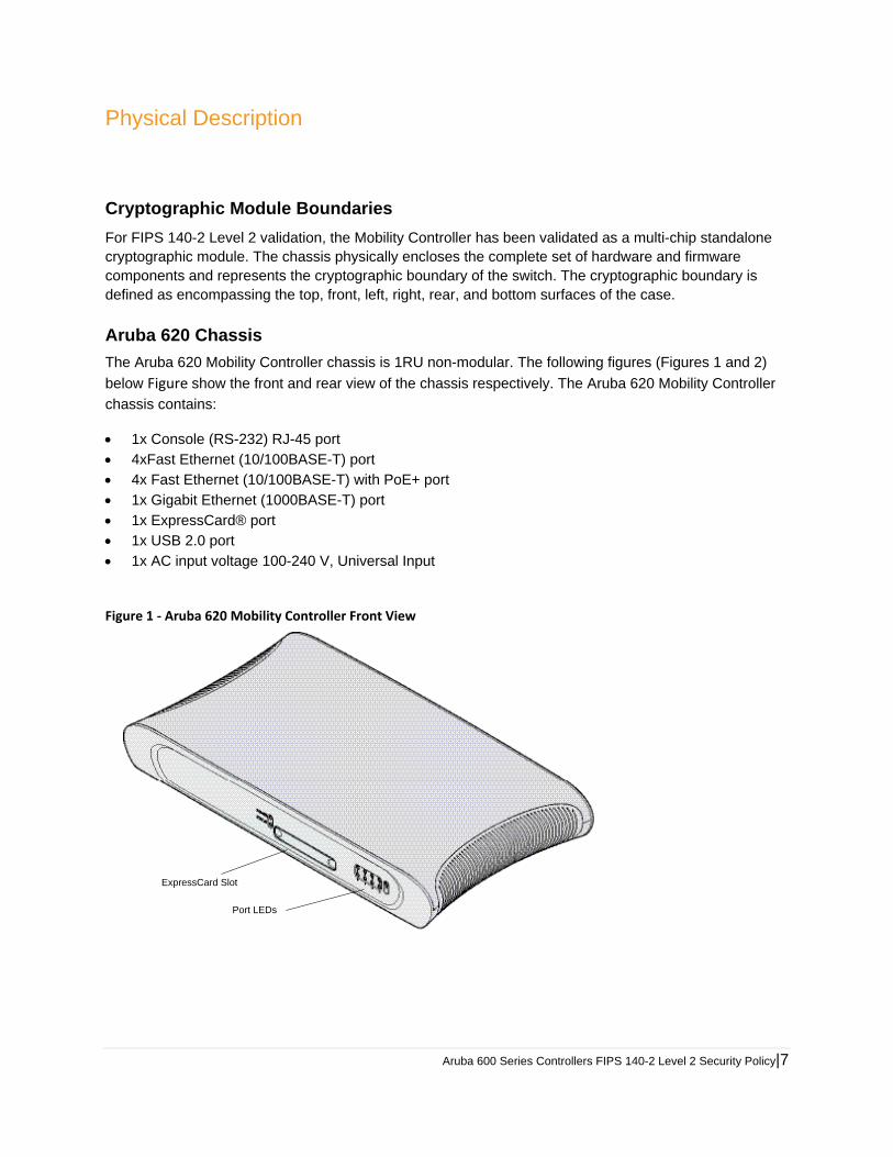
Aruba 620 Chassis
The Aruba 620 Mobility Controller chassis is 1RU non-modular. The following figures (Figures 1 and 2)
below Figure show the front and rear view of the chassis respectively. The Aruba 620 Mobility Controller
chassis contains:
1x Console (RS-232) RJ-45 port 4xFast Ethernet (10/100BASE-T) port 4x Fast Ethernet (10/100BASE-T) with PoE+ port 1x Gigabit Ethernet (1000BASE-T) port 1x ExpressCard® port 1x USB 2.0 port 1x AC input voltage 100-240 V, Universal Input
Figure 1 ‐ Aruba 620 Mobility Controller Front View
ExpressCard Slot
Port LEDs
8| Aruba 600 Series Controllers FIPS 140-2 Level 2 Security Policy
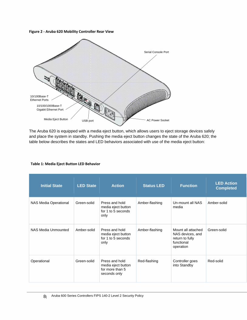
Figure 2 ‐ Aruba 620 Mobility Controller Rear View
The Aruba 620 is equipped with a media eject button, which allows users to eject storage devices safely and place the system in standby. Pushing the media eject button changes the state of the Aruba 620; the table below describes the states and LED behaviors associated with use of the media eject button:
Table 1: Media Eject Button LED Behavior
Initial State LED State Action Status LED Function LED Action Completed
NAS Media Operational Green-solid Press and hold media eject button for 1 to 5 seconds only
Amber-flashing Un-mount all NAS media
Amber-solid
NAS Media Unmounted Amber-solid Press and hold media eject button for 1 to 5 seconds only
Amber-flashing Mount all attached NAS devices, and return to fully functional operation
Green-solid
Operational Green-solid Press and hold media eject button for more than 5 seconds only
Red-flashing Controller goes into Standby
Red-solid
10/100/1000Base-TGigabit Ethernet Port
10/100Base-TEthernet Ports
USB portMedia Eject Button
Serial Console Port
AC Power Socket
Aruba 600 Series Controllers FIPS 140-2 Level 2 Security Policy|9
Operating with NAS Media un-mounted
Amber-solid Press and hold media eject button for more than 5 seconds only
Red-flashing Controller goes into Standby
Red-solid
Standby Red-solid Press media eject button
Amber-flashing Controller wake-up Green-solid
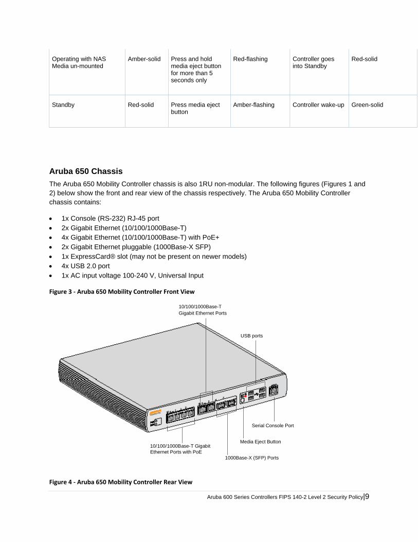
Aruba 650 Chassis
The Aruba 650 Mobility Controller chassis is also 1RU non-modular. The following figures (Figures 1 and 2) below show the front and rear view of the chassis respectively. The Aruba 650 Mobility Controller chassis contains:
1x Console (RS-232) RJ-45 port 2x Gigabit Ethernet (10/100/1000Base-T) 4x Gigabit Ethernet (10/100/1000Base-T) with PoE+ 2x Gigabit Ethernet pluggable (1000Base-X SFP) 1x ExpressCard® slot (may not be present on newer models) 4x USB 2.0 port 1x AC input voltage 100-240 V, Universal Input
Figure 3 ‐ Aruba 650 Mobility Controller Front View
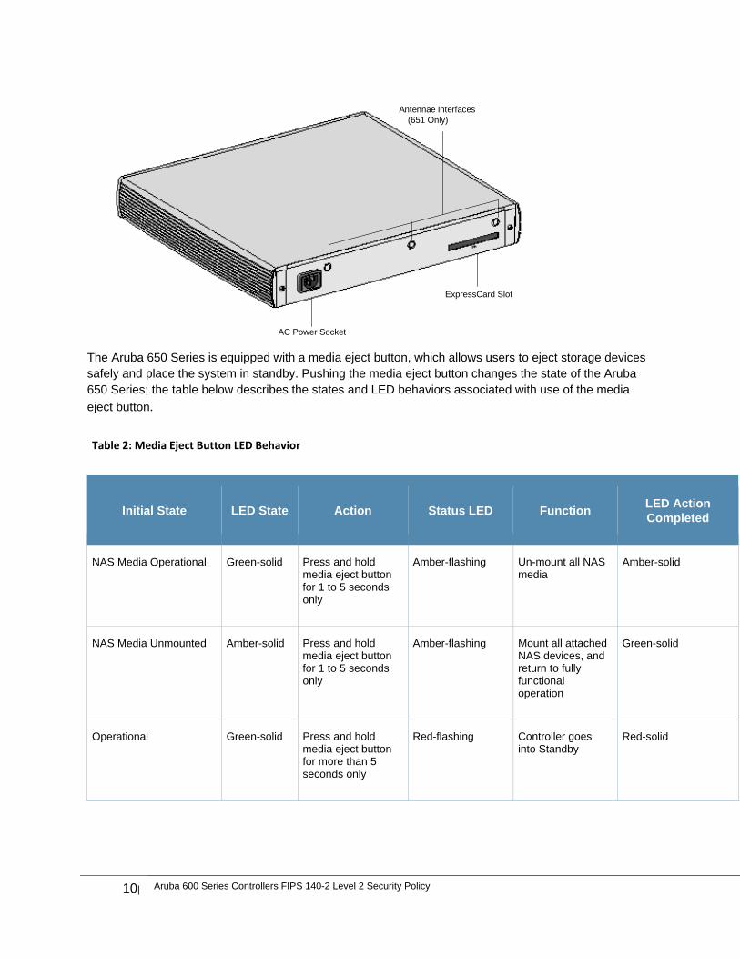
Figure 4 ‐ Aruba 650 Mobility Controller Rear View
10/100/1000Base-T GigabitEthernet Ports with PoE
1000Base-X (SFP) Ports
USB ports
10/100/1000Base-TGigabit Ethernet Ports
Media Eject Button
Serial Console Port
10| Aruba 600 Series Controllers FIPS 140-2 Level 2 Security Policy
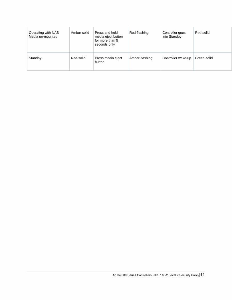
The Aruba 650 Series is equipped with a media eject button, which allows users to eject storage devices safely and place the system in standby. Pushing the media eject button changes the state of the Aruba 650 Series; the table below describes the states and LED behaviors associated with use of the media
eject button.
Table 2: Media Eject Button LED Behavior
Initial State LED State Action Status LED Function LED Action Completed
NAS Media Operational Green-solid Press and hold media eject button for 1 to 5 seconds only
Amber-flashing Un-mount all NAS media
Amber-solid
NAS Media Unmounted Amber-solid Press and hold media eject button for 1 to 5 seconds only
Amber-flashing Mount all attached NAS devices, and return to fully functional operation
Green-solid
Operational Green-solid Press and hold media eject button for more than 5 seconds only
Red-flashing Controller goes into Standby
Red-solid
AC Power Socket
ExpressCard Slot
Antennae Interfaces(651 Only)
Aruba 600 Series Controllers FIPS 140-2 Level 2 Security Policy|11
Operating with NAS Media un-mounted
Amber-solid Press and hold media eject button for more than 5 seconds only
Red-flashing Controller goes into Standby
Red-solid
Standby Red-solid Press media eject button
Amber-flashing Controller wake-up Green-solid
12| Aruba 600 Series Controllers FIPS 140-2 Level 2 Security Policy
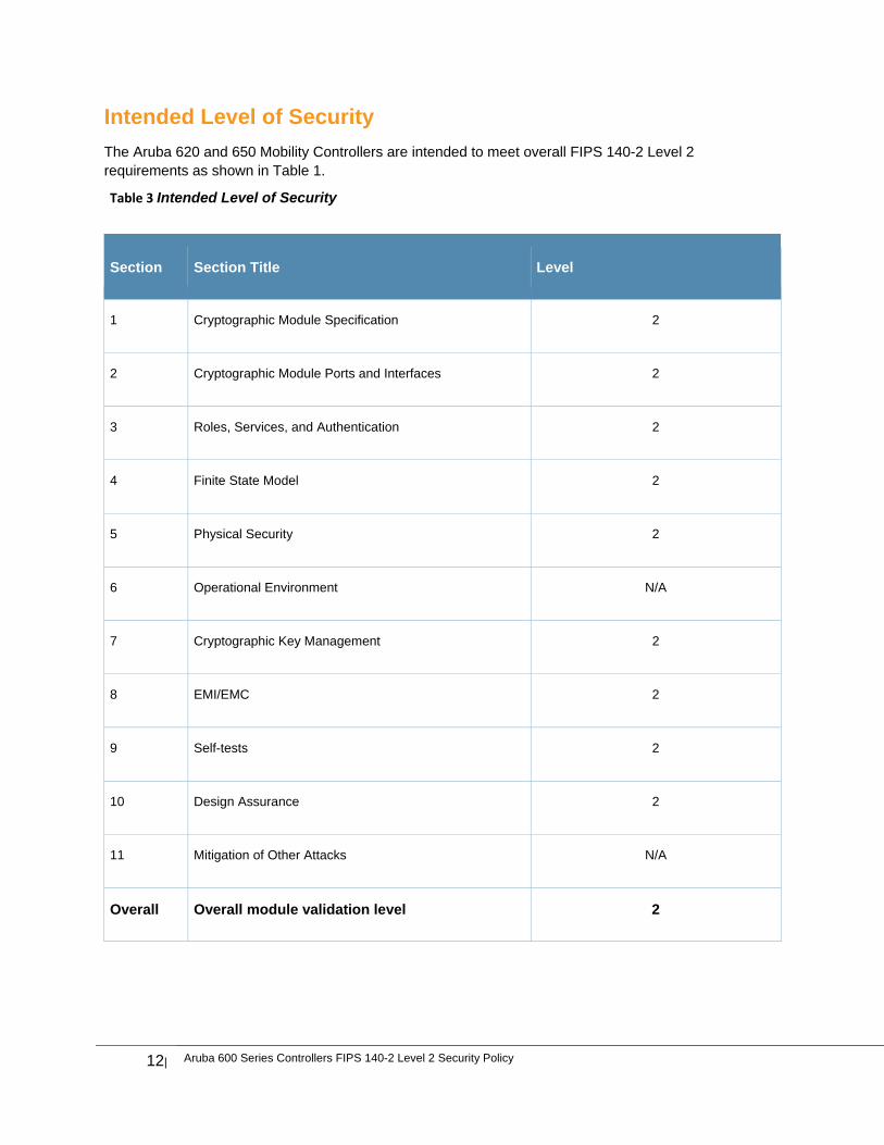
Intended Level of Security
The Aruba 620 and 650 Mobility Controllers are intended to meet overall FIPS 140-2 Level 2 requirements as shown in Table 1.
Table 3 Intended Level of Security
Section Section Title Level
1 Cryptographic Module Specification 2
2 Cryptographic Module Ports and Interfaces 2
3 Roles, Services, and Authentication 2
4 Finite State Model 2
5 Physical Security 2
6 Operational Environment N/A
7 Cryptographic Key Management 2
8 EMI/EMC 2
9 Self-tests 2
10 Design Assurance 2
11 Mitigation of Other Attacks N/A
Overall Overall module validation level 2
Aruba 600 Series Controllers FIPS 140-2 Level 2 Security Policy|13
Physical Security
The Aruba Controller is a scalable, multi-processor standalone network device and is enclosed in a robust housing. The controller enclosure is resistant to probing and is opaque within the visible spectrum. The enclosure of the module has been designed to satisfy FIPS 140-2 Level 2 physical security requirements.
The Aruba 600 Series Controller requires Tamper-Evident Labels (TELs) to allow the detection of the opening of the chassis cover and to block the Serial console port.
To protect the Aruba 600 Series Controller from any tampering with the product, TELs should be applied by the Crypto Officer as covered under “Tamper-Evident Labels” in this document.
Operational Environment
The operational environment is non-modifiable. The control plane Operating System (OS) is Linux, a real-time, multi-threaded operating system that supports memory protection between processes. Access to the underlying Linux implementation is not provided directly. Only Aruba Networks provided interfaces are used, and the CLI is a restricted command set.
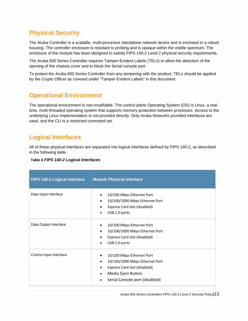
Logical Interfaces
All of these physical interfaces are separated into logical interfaces defined by FIPS 140-2, as described in the following table.
Table 4 FIPS 140-2 Logical Interfaces
FIPS 140-2 Logical Interface Module Physical Interface
Data Input Interface 10/100 Mbps Ethernet Port
10/100/1000 Mbps Ethernet Port
Express Card slot (disabled)
USB 2.0 ports
Data Output Interface 10/100 Mbps Ethernet Port
10/100/1000 Mbps Ethernet Port
Express Card slot (disabled)
USB 2.0 ports
Control Input Interface 10/100 Mbps Ethernet Port
10/100/1000 Mbps Ethernet Port
Express Card slot (disabled)
Media Eject Button
Serial Console port (disabled)
14| Aruba 600 Series Controllers FIPS 140-2 Level 2 Security Policy
Table 4 FIPS 140-2 Logical Interfaces
Status Output Interface 10/100 Mbps Ethernet Port
10/100/1000 Mbps Ethernet Port
LEDs
Serial Console port (disabled)
Power Interface Power Supply
Power over Ethernet (PoE)
Data input and output, control input, status output, and power interfaces are defined as follows:
Data input and output are the packets that use the firewall, VPN, and routing functionality of the modules.
Control input consists of manual control inputs for power and reset through the power and reset switch. It also consists of all of the data that is entered into the controller while using the management interfaces.
Status output consists of the status indicators displayed through the LEDs, the status data that is output from the controller while using the management interfaces, and the log file.
LEDs indicate the physical state of the module, such as power-up (or rebooting), utilization level, activation state (including fan, ports, and power). The log file records the results of self-tests, configuration errors, and monitoring data.
A power supply is used to connect the electric power cable.
The controller distinguishes between different forms of data, control, and status traffic over the network ports by analyzing the packets header information and contents.
Roles and Services
The Aruba Controller supports role-based authentication. There are two roles in the module (as required by FIPS 140-2 Level 2) that operators may assume: a Crypto Officer role and a User role. The Administrator maps to the Crypto-Officer role and the client Users map to the User role.
Crypto Officer Role
The Crypto Officer role has the ability to configure, manage, and monitor the controller. Three management interfaces can be used for this purpose:
SSHv2 CLI
The Crypto Officer can use the CLI to perform non-security-sensitive and security-sensitive monitoring and configuration. The CLI can be accessed remotely by using the SSHv2 secured management session over the Ethernet ports or locally over the serial port. In FIPS mode, the serial port is disabled.
Web Interface
The Crypto Officer can use the Web Interface as an alternative to the CLI. The Web Interface provides a highly intuitive, graphical interface for a comprehensive set of controller management
Aruba 600 Series Controllers FIPS 140-2 Level 2 Security Policy|15
tools. The Web Interface can be accessed from a TLS-enabled Web browser using HTTPS (HTTP with Secure Socket Layer) on logical port 4343.
SNMP v3
The Crypto Officer can also use SNMPv3 to remotely perform non-security-sensitive monitoring and
use ‘get’ and ‘getnext’ commands.
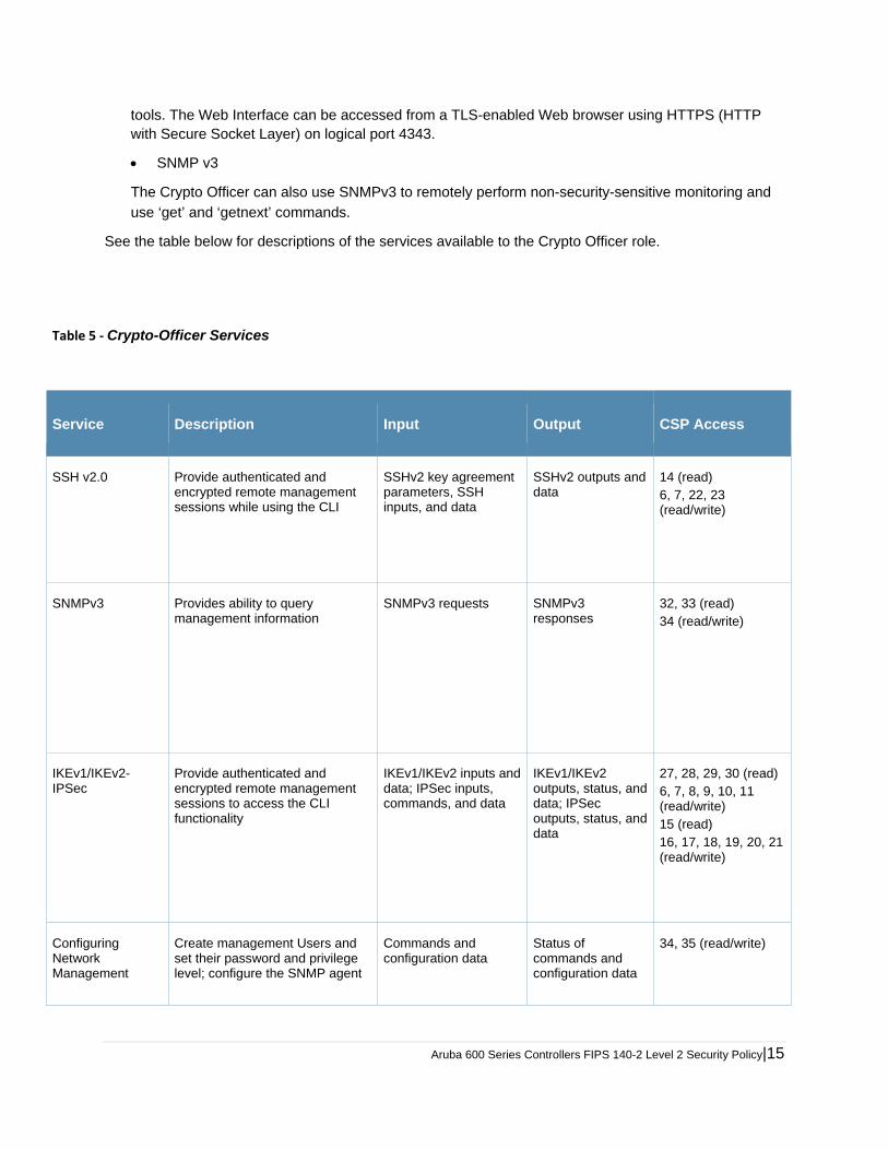
See the table below for descriptions of the services available to the Crypto Officer role.
Table 5 ‐ Crypto-Officer Services
Service Description Input Output CSP Access
SSH v2.0 Provide authenticated and encrypted remote management sessions while using the CLI
SSHv2 key agreement parameters, SSH inputs, and data
SSHv2 outputs and data
14 (read) 6, 7, 22, 23 (read/write)
SNMPv3 Provides ability to query management information
SNMPv3 requests SNMPv3 responses
32, 33 (read) 34 (read/write)
IKEv1/IKEv2-IPSec
Provide authenticated and encrypted remote management sessions to access the CLI functionality
IKEv1/IKEv2 inputs and data; IPSec inputs, commands, and data
IKEv1/IKEv2 outputs, status, and data; IPSec outputs, status, and data
27, 28, 29, 30 (read) 6, 7, 8, 9, 10, 11 (read/write) 15 (read) 16, 17, 18, 19, 20, 21 (read/write)
Configuring Network Management
Create management Users and set their password and privilege level; configure the SNMP agent
Commands and configuration data
Status of commands and configuration data
34, 35 (read/write)

16| Aruba 600 Series Controllers FIPS 140-2 Level 2 Security Policy
Table 5 ‐ Crypto-Officer Services
Configuring Module Platform
Define the platform subsystem firmware of the module by entering Bootrom Monitor Mode, File System, fault report, message logging, and other platform related commands
Commands and configuration data
Status of commands and configuration data
None
Configuring Hardware Controllers
Define synchronization features for module
Commands and configuration data
Status of commands and configuration data
None
Configuring Internet Protocol
Set IP functionality Commands and configuration data
Status of commands and configuration data
None
Configuring Quality of Service (QoS)
Configure QOS values for module Commands and configuration data
Status of commands and configuration data
None
Configuring VPN Configure Public Key Infrastructure (PKI); configure the Internet Key Exchange (IKEv1/IKEv2) Security Protocol; configure the IPSec protocol
Commands and configuration data
Status of commands and configuration data
17 (read/write)
Configuring DHCP Configure DHCP on module Commands and configuration data
Status of commands and configuration data
None
Configuring Security
Define security features for module, including Access List, Authentication, Authorization and Accounting (AAA), and firewall functionality
Commands and configuration data
Status of commands and configuration data
12, 13, 14 (read/write)
Manage Certificates
Install, rename, and delete X.509 certificates
Commands and configuration data; Certificates and keys
Status of certificates, commands, and configuration
27, 27,29, 30 (read/write)
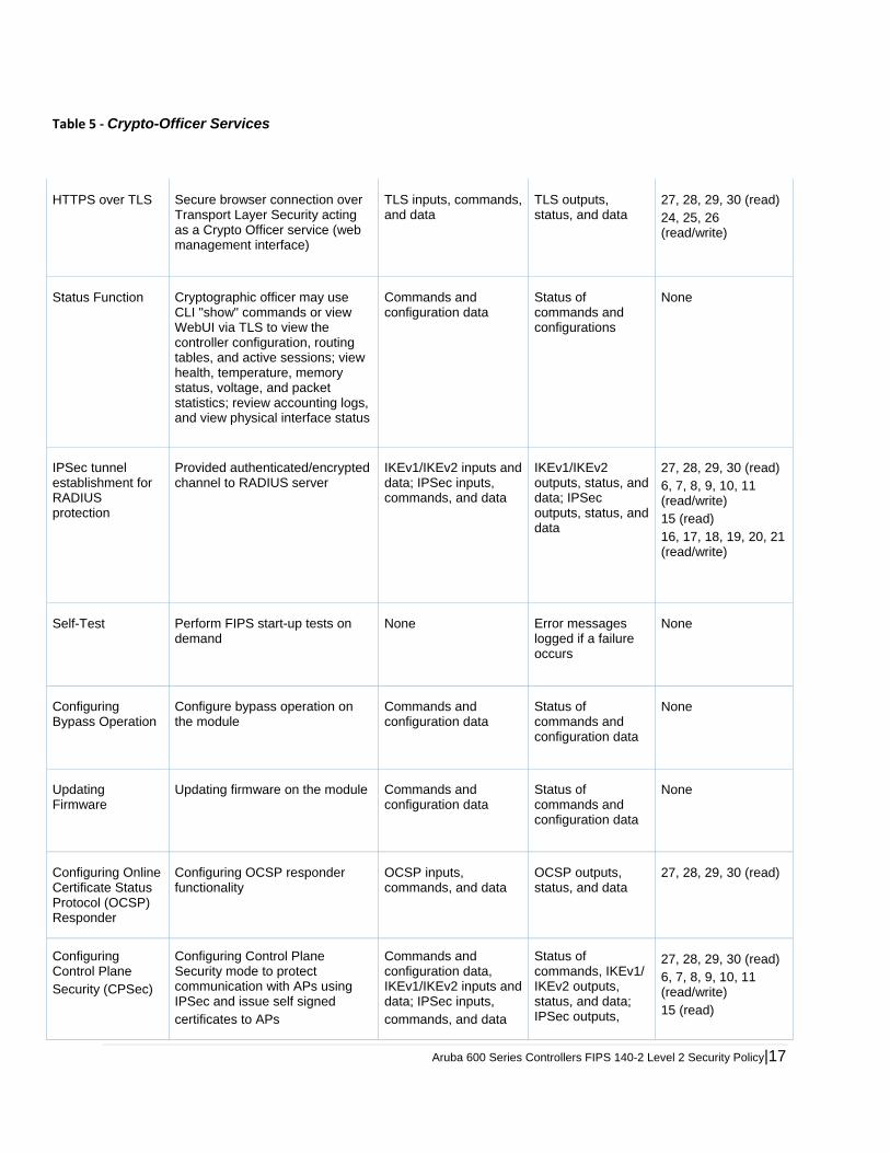
Aruba 600 Series Controllers FIPS 140-2 Level 2 Security Policy|17
Table 5 ‐ Crypto-Officer Services
HTTPS over TLS Secure browser connection over Transport Layer Security acting as a Crypto Officer service (web management interface)
TLS inputs, commands, and data
TLS outputs, status, and data
27, 28, 29, 30 (read) 24, 25, 26 (read/write)
Status Function Cryptographic officer may use CLI "show" commands or view WebUI via TLS to view the controller configuration, routing tables, and active sessions; view health, temperature, memory status, voltage, and packet statistics; review accounting logs, and view physical interface status
Commands and configuration data
Status of commands and configurations
None
IPSec tunnel establishment for RADIUS protection
Provided authenticated/encrypted channel to RADIUS server
IKEv1/IKEv2 inputs and data; IPSec inputs, commands, and data
IKEv1/IKEv2 outputs, status, and data; IPSec outputs, status, and data
27, 28, 29, 30 (read) 6, 7, 8, 9, 10, 11 (read/write) 15 (read) 16, 17, 18, 19, 20, 21 (read/write)
Self-Test Perform FIPS start-up tests on demand
None Error messages logged if a failure occurs
None
Configuring Bypass Operation
Configure bypass operation on the module
Commands and configuration data
Status of commands and configuration data
None
Updating Firmware
Updating firmware on the module Commands and configuration data
Status of commands and configuration data
None
Configuring Online Certificate Status Protocol (OCSP) Responder
Configuring OCSP responder functionality
OCSP inputs, commands, and data
OCSP outputs, status, and data
27, 28, 29, 30 (read)
Configuring Control Plane Security (CPSec)
Configuring Control Plane Security mode to protect communication with APs using IPSec and issue self signed certificates to APs
Commands and configuration data, IKEv1/IKEv2 inputs anddata; IPSec inputs, commands, and data
Status of commands, IKEv1/ IKEv2 outputs, status, and data; IPSec outputs,
27, 28, 29, 30 (read) 6, 7, 8, 9, 10, 11 (read/write) 15 (read)
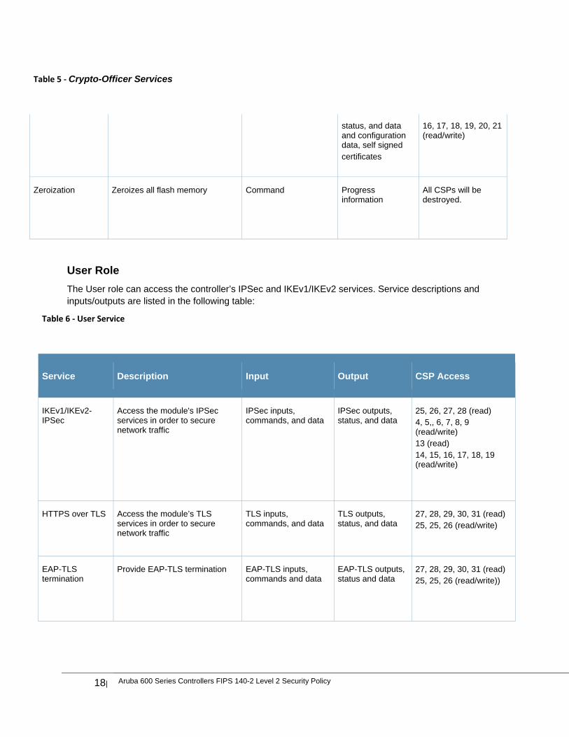
18| Aruba 600 Series Controllers FIPS 140-2 Level 2 Security Policy
Table 5 ‐ Crypto-Officer Services
status, and data and configuration data, self signed certificates
16, 17, 18, 19, 20, 21 (read/write)
Zeroization Zeroizes all flash memory Command Progress information
All CSPs will be destroyed.
User Role
The User role can access the controller’s IPSec and IKEv1/IKEv2 services. Service descriptions and inputs/outputs are listed in the following table:
Table 6 ‐ User Service
Service Description Input Output CSP Access
IKEv1/IKEv2-IPSec
Access the module's IPSec services in order to secure network traffic
IPSec inputs, commands, and data
IPSec outputs, status, and data
25, 26, 27, 28 (read) 4, 5,, 6, 7, 8, 9 (read/write) 13 (read) 14, 15, 16, 17, 18, 19 (read/write)
HTTPS over TLS Access the module’s TLS services in order to secure network traffic
TLS inputs, commands, and data
TLS outputs, status, and data
27, 28, 29, 30, 31 (read) 25, 25, 26 (read/write)
EAP-TLS termination
Provide EAP-TLS termination EAP-TLS inputs, commands and data
EAP-TLS outputs, status and data
27, 28, 29, 30, 31 (read) 25, 25, 26 (read/write))
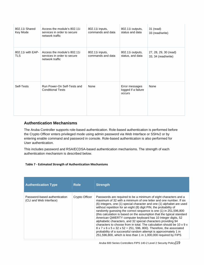
Aruba 600 Series Controllers FIPS 140-2 Level 2 Security Policy|19
802.11i Shared Key Mode
Access the module’s 802.11i services in order to secure network traffic
802.11i inputs, commands and data
802.11i outputs, status and data
31 (read) 33 (read/write)
802.11i with EAP-TLS
Access the module’s 802.11i services in order to secure network traffic
802.11i inputs, commands and data
802.11i outputs, status, and data
27, 28, 29, 30 (read) 33, 34 (read/write)
Self-Tests Run Power-On Self-Tests and Conditional Tests
None Error messages logged if a failure occurs
None
Authentication Mechanisms
The Aruba Controller supports role-based authentication. Role-based authentication is performed before the Crypto Officer enters privileged mode using admin password via Web Interface or SSHv2 or by entering enable command and password in console. Role-based authentication is also performed for User authentication.
This includes password and RSA/ECDSA-based authentication mechanisms. The strength of each authentication mechanism is described below.
Table 7 ‐ Estimated Strength of Authentication Mechanisms
Authentication Type Role Strength
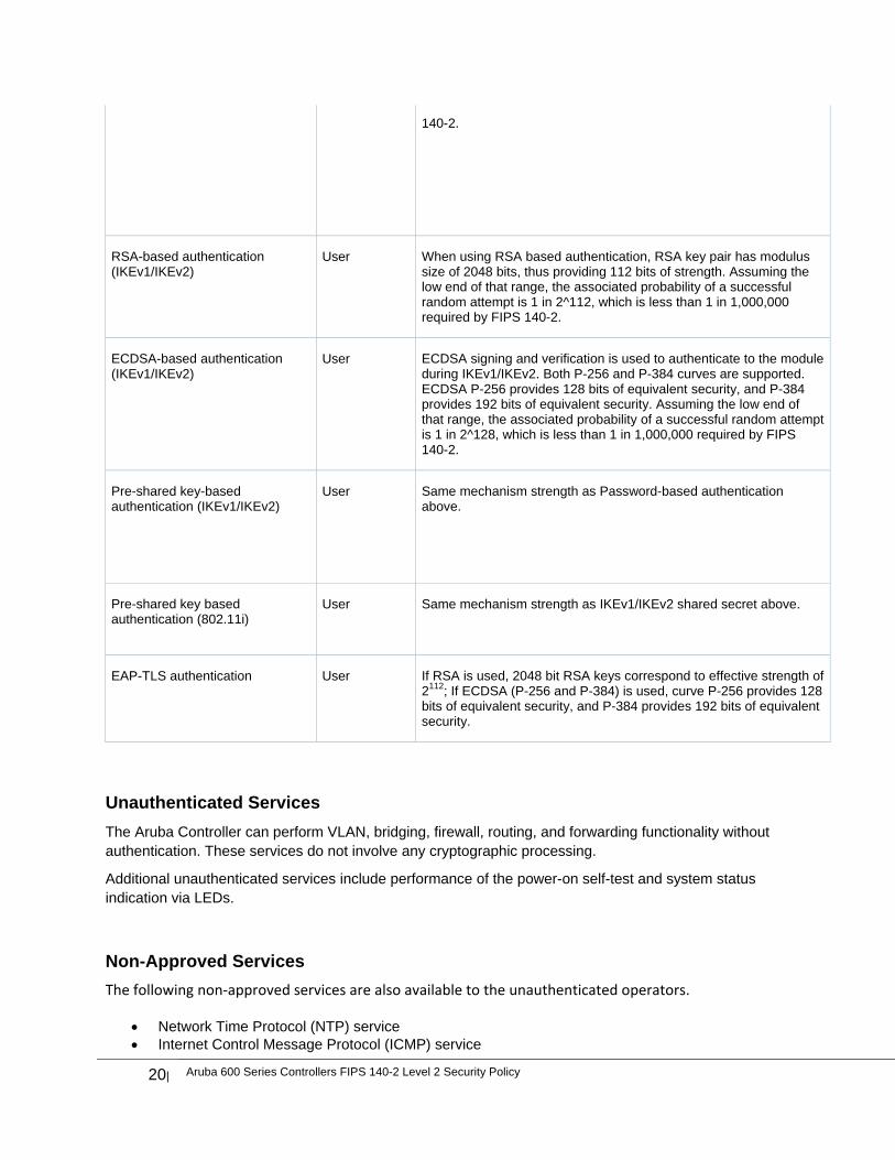
Password-based authentication (CLI and Web Interface)
Crypto Officer Passwords are required to be a minimum of eight characters and a maximum of 32 with a minimum of one letter and one number. If six (6) integers, one (1) special character and one (1) alphabet are used without repetition for an eight (8) digit PIN, the probability of randomly guessing the correct sequence is one (1) in 251,596,800 (this calculation is based on the assumption that the typical standard American QWERTY computer keyboard has 10 Integer digits, 52 alphabetic characters, and 32 special characters providing 94 characters to choose from in total. The calculation should be 10 x 9 x 8 x 7 x 6 x 5 x 32 x 52 = 251, 596, 800). Therefore, the associated probability of a successful random attempt is approximately 1 in 251,596,800, which is less than 1 in 1,000,000 required by FIPS
20| Aruba 600 Series Controllers FIPS 140-2 Level 2 Security Policy
140-2.
RSA-based authentication (IKEv1/IKEv2)
User When using RSA based authentication, RSA key pair has modulus size of 2048 bits, thus providing 112 bits of strength. Assuming the low end of that range, the associated probability of a successful random attempt is 1 in 2^112, which is less than 1 in 1,000,000 required by FIPS 140-2.
ECDSA-based authentication (IKEv1/IKEv2)
User ECDSA signing and verification is used to authenticate to the module during IKEv1/IKEv2. Both P-256 and P-384 curves are supported. ECDSA P-256 provides 128 bits of equivalent security, and P-384 provides 192 bits of equivalent security. Assuming the low end of that range, the associated probability of a successful random attempt is 1 in 2^128, which is less than 1 in 1,000,000 required by FIPS 140-2.
Pre-shared key-based authentication (IKEv1/IKEv2)
User Same mechanism strength as Password-based authentication above.
Pre-shared key based authentication (802.11i)
User Same mechanism strength as IKEv1/IKEv2 shared secret above.
EAP-TLS authentication User If RSA is used, 2048 bit RSA keys correspond to effective strength of 2112; If ECDSA (P-256 and P-384) is used, curve P-256 provides 128 bits of equivalent security, and P-384 provides 192 bits of equivalent security.
Unauthenticated Services
The Aruba Controller can perform VLAN, bridging, firewall, routing, and forwarding functionality without authentication. These services do not involve any cryptographic processing.
Additional unauthenticated services include performance of the power-on self-test and system status indication via LEDs.
Non-Approved Services
The following non‐approved services are also available to the unauthenticated operators.
Network Time Protocol (NTP) service Internet Control Message Protocol (ICMP) service
Aruba 600 Series Controllers FIPS 140-2 Level 2 Security Policy|21
VLAN service Network bridging service Network Address Resolution Protocol (ARP) service Packets routing, switching and forwarding
Cryptographic Key Management
Implemented Algorithms
FIPS-approved cryptographic algorithms have been implemented in firmware and hardware.
Hardware encryption acceleration is provided for bulk cryptographic operations for the following FIPS approved algorithms:
o AES (Cert. #779) o Triple-DES (Cert. #673) o SHS (Cert. #781) o HMAC (Cert. #426)
The firmware supports the following cryptographic implementations. ArubaOS OpenSSL Module implements the following FIPS-approved algorithms:
o AES (Cert. #2680) o CVL (Cert. #152) o DRBG (Cert. #433) o ECDSA (Cert. #469) o HMAC (Cert. #1666) o KBKDF (Cert. #16) o RSA (Cert. #1379) o SHS (Cert. #2249) o Triple-DES (Cert. #1607)
Note:
o RSA (Cert. #1379; non-compliant with the functions from the CAVP Historical RSA List)
o ECDSA (Cert. #469; non-compliant with the functions from the CAVP Historical ECDSA List)
ArubaOS Crypto Module implementation supports the following FIPS Approved Algorithms: o AES (Cert. #2677) o CVL (Cert. #150) o ECDSA (Cert. #466) o HMAC (Cert. #1663) o RSA (Cert. #1376) o SHS (Cert. #2246) o Triple-DES (Cert. #1605)
Note:
o RSA (Cert. #1376; non-compliant with the functions from the CAVP Historical RSA List) o ECDSA (Cert. #466; non-compliant with the functions from the CAVP Historical ECDSA List)
ArubaOS UBOOT Bootloader implements the following FIPS-approved algorithms: o RSA (Cert. #1380)
22| Aruba 600 Series Controllers FIPS 140-2 Level 2 Security Policy
o SHS (Cert. #2250)
Non‐FIPS Approved Algorithms Allowed in FIPS Mode
Diffie-Hellman (key agreement; key establishment methodology provides 112 bits of encryption
strength; non-compliant less than 112-bits of encryption strength)
EC Diffie-Hellman (key agreement; key establishment methodology provides 128 or 192 bits of
encryption strength)
NDRNG
RSA (key wrapping; key establishment methodology provides 112 bits of encryption strength;
non-compliant less than 112-bits of encryption strength)
Non-FIPS Approved Algorithms
The cryptographic module implements the following non-approved algorithms that are not permitted for use in the FIPS 140-2 mode of operations:
DES HMAC-MD5 MD5 RC4
Critical Security Parameters
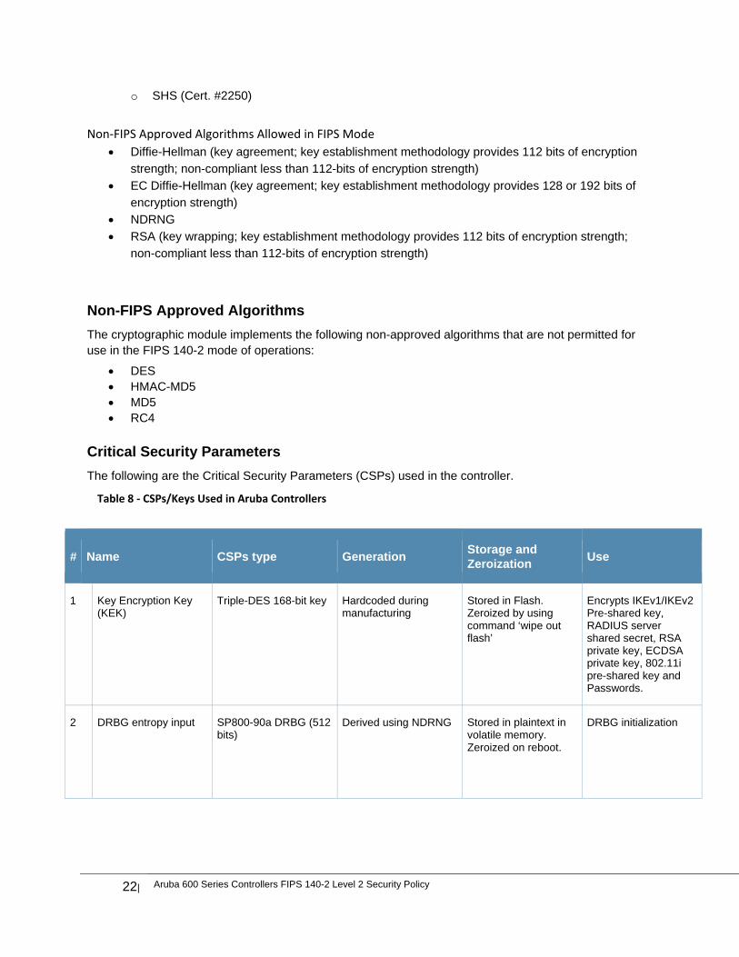
The following are the Critical Security Parameters (CSPs) used in the controller.
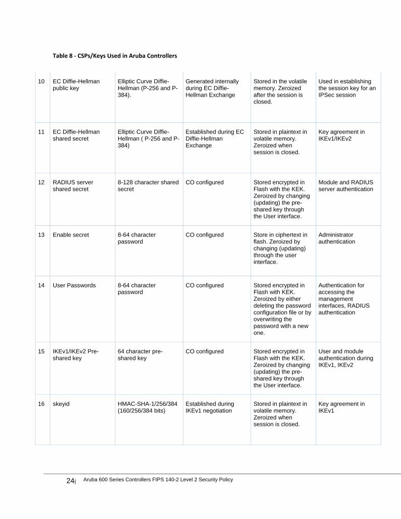
Table 8 ‐ CSPs/Keys Used in Aruba Controllers
# Name CSPs type Generation Storage and Zeroization
Use
1 Key Encryption Key (KEK)
Triple-DES 168-bit key Hardcoded during manufacturing
Stored in Flash. Zeroized by using command ‘wipe out flash’
Encrypts IKEv1/IKEv2 Pre-shared key, RADIUS server shared secret, RSA private key, ECDSA private key, 802.11i pre-shared key and Passwords.
2 DRBG entropy input SP800-90a DRBG (512 bits)
Derived using NDRNG Stored in plaintext in volatile memory. Zeroized on reboot.
DRBG initialization
Aruba 600 Series Controllers FIPS 140-2 Level 2 Security Policy|23
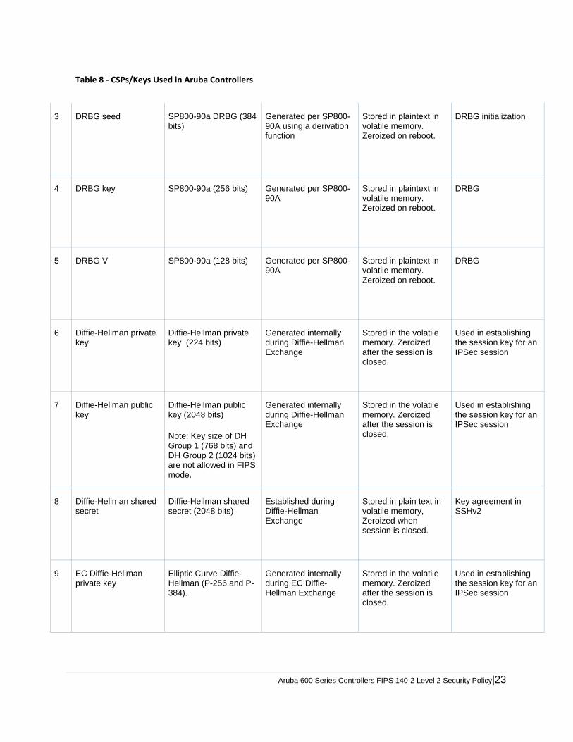
Table 8 ‐ CSPs/Keys Used in Aruba Controllers
3 DRBG seed SP800-90a DRBG (384 bits)
Generated per SP800-90A using a derivation function
Stored in plaintext in volatile memory. Zeroized on reboot.
DRBG initialization
4 DRBG key SP800-90a (256 bits) Generated per SP800-90A
Stored in plaintext in volatile memory. Zeroized on reboot.
DRBG
5 DRBG V SP800-90a (128 bits) Generated per SP800-90A
Stored in plaintext in volatile memory. Zeroized on reboot.
DRBG
6 Diffie-Hellman private key
Diffie-Hellman private key (224 bits)
Generated internally during Diffie-Hellman Exchange
Stored in the volatile memory. Zeroized after the session is closed.
Used in establishing the session key for an IPSec session
7 Diffie-Hellman public key
Diffie-Hellman public key (2048 bits) Note: Key size of DH Group 1 (768 bits) and DH Group 2 (1024 bits) are not allowed in FIPS mode.
Generated internally during Diffie-Hellman Exchange
Stored in the volatile memory. Zeroized after the session is closed.
Used in establishing the session key for an IPSec session
8 Diffie-Hellman shared secret
Diffie-Hellman shared secret (2048 bits)
Established during Diffie-Hellman Exchange
Stored in plain text in volatile memory, Zeroized when session is closed.
Key agreement in SSHv2
9 EC Diffie-Hellman private key
Elliptic Curve Diffie-Hellman (P-256 and P-384).
Generated internally during EC Diffie-Hellman Exchange
Stored in the volatile memory. Zeroized after the session is closed.
Used in establishing the session key for an IPSec session
24| Aruba 600 Series Controllers FIPS 140-2 Level 2 Security Policy
Table 8 ‐ CSPs/Keys Used in Aruba Controllers
10 EC Diffie-Hellman public key
Elliptic Curve Diffie-Hellman (P-256 and P-384).
Generated internally during EC Diffie-Hellman Exchange
Stored in the volatile memory. Zeroized after the session is closed.
Used in establishing the session key for an IPSec session
11 EC Diffie-Hellman shared secret
Elliptic Curve Diffie-Hellman ( P-256 and P-384)
Established during EC Diffie-Hellman Exchange
Stored in plaintext in volatile memory. Zeroized when session is closed.
Key agreement in IKEv1/IKEv2
12 RADIUS server shared secret
8-128 character shared secret
CO configured Stored encrypted in Flash with the KEK. Zeroized by changing (updating) the pre-shared key through the User interface.
Module and RADIUS server authentication
13 Enable secret 8-64 character password
CO configured Store in ciphertext in flash. Zeroized by changing (updating) through the user interface.
Administrator authentication
14 User Passwords 8-64 character password
CO configured Stored encrypted in Flash with KEK. Zeroized by either deleting the password configuration file or by overwriting the password with a new one.
Authentication for accessing the management interfaces, RADIUS authentication
15 IKEv1/IKEv2 Pre-shared key
64 character pre-shared key
CO configured Stored encrypted in Flash with the KEK. Zeroized by changing (updating) the pre-shared key through the User interface.
User and module authentication during IKEv1, IKEv2
16 skeyid HMAC-SHA-1/256/384 (160/256/384 bits)
Established during IKEv1 negotiation
Stored in plaintext in volatile memory. Zeroized when session is closed.
Key agreement in IKEv1
Aruba 600 Series Controllers FIPS 140-2 Level 2 Security Policy|25
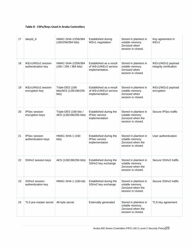
Table 8 ‐ CSPs/Keys Used in Aruba Controllers
17 skeyid_d HMAC-SHA-1/256/384 (160/256/384 bits)
Established during IKEv1 negotiation
Stored in plaintext in volatile memory. Zeroized when session is closed.
Key agreement in IKEv1
18 IKEv1/IKEv2 session authentication key
HMAC-SHA-1/256/384 (160 / 256 / 384 bits)
Established as a result of IKEv1/IKEv2 service implementation.
Stored in plaintext in volatile memory. Zeroized when session is closed.
IKEv1/IKEv2 payload integrity verification
19 IKEv1/IKEv2 session encryption key
Triple-DES (168 bits/AES (128/196/256 bits)
Established as a result of IKEv1/IKEv2 service implementation.
Stored in plaintext in volatile memory. Zeroized when session is closed.
IKEv1/IKEv2 payload encryption
20 IPSec session encryption keys
Triple-DES (168 bits / AES (128/196/256 bits)
Established during the IPSec service implementation
Stored in plaintext in volatile memory. Zeroized when the session is closed.
Secure IPSec traffic
21 IPSec session authentication keys
HMAC-SHA-1 (160 bits)
Established during the IPSec service implementation
Stored in plaintext in volatile memory. Zeroized when the session is closed.
User authentication
22 SSHv2 session keys AES (128/196/256 bits) Established during the SSHv2 key exchange
Stored in plaintext in volatile memory. Zeroized when the session is closed.
Secure SSHv2 traffic
23 SSHv2 session authentication key
HMAC-SHA-1 (160-bit) Established during the SSHv2 key exchange
Stored in plaintext in volatile memory. Zeroized when the session is closed.
Secure SSHv2 traffic
24 TLS pre-master secret 48 byte secret Externally generated Stored in plaintext in volatile memory. Zeroized when the session is closed.
TLS key agreement
26| Aruba 600 Series Controllers FIPS 140-2 Level 2 Security Policy
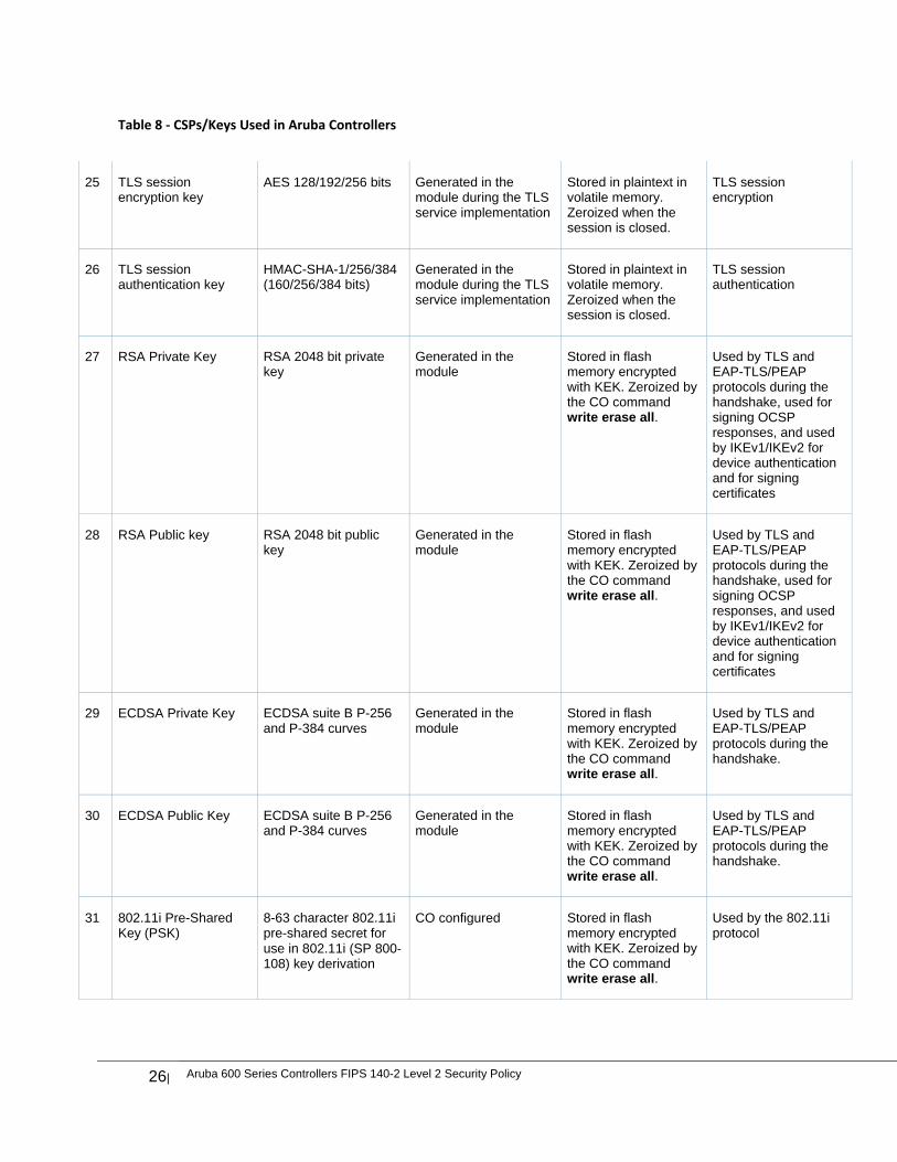
Table 8 ‐ CSPs/Keys Used in Aruba Controllers
25 TLS session encryption key
AES 128/192/256 bits Generated in the module during the TLS service implementation
Stored in plaintext in volatile memory. Zeroized when the session is closed.
TLS session encryption
26 TLS session authentication key
HMAC-SHA-1/256/384 (160/256/384 bits)
Generated in the module during the TLS service implementation
Stored in plaintext in volatile memory. Zeroized when the session is closed.
TLS session authentication
27 RSA Private Key RSA 2048 bit private key
Generated in the module
Stored in flash memory encrypted with KEK. Zeroized by the CO command write erase all.
Used by TLS and EAP-TLS/PEAP protocols during the handshake, used for signing OCSP responses, and used by IKEv1/IKEv2 for device authentication and for signing certificates
28 RSA Public key RSA 2048 bit public key
Generated in the module
Stored in flash memory encrypted with KEK. Zeroized by the CO command write erase all.
Used by TLS and EAP-TLS/PEAP protocols during the handshake, used for signing OCSP responses, and used by IKEv1/IKEv2 for device authentication and for signing certificates
29 ECDSA Private Key ECDSA suite B P-256 and P-384 curves
Generated in the module
Stored in flash memory encrypted with KEK. Zeroized by the CO command write erase all.
Used by TLS and EAP-TLS/PEAP protocols during the handshake.
30 ECDSA Public Key ECDSA suite B P-256 and P-384 curves
Generated in the module
Stored in flash memory encrypted with KEK. Zeroized by the CO command write erase all.
Used by TLS and EAP-TLS/PEAP protocols during the handshake.
31 802.11i Pre-Shared Key (PSK)
8-63 character 802.11i pre-shared secret for use in 802.11i (SP 800‐108) key derivation
CO configured Stored in flash memory encrypted with KEK. Zeroized by the CO command write erase all.
Used by the 802.11i protocol
Aruba 600 Series Controllers FIPS 140-2 Level 2 Security Policy|27
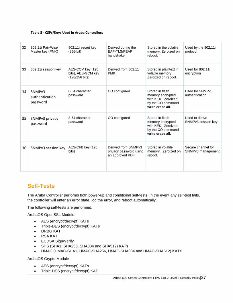
Table 8 ‐ CSPs/Keys Used in Aruba Controllers
32 802.11i Pair-Wise Master key (PMK)
802.11i secret key (256-bit)
Derived during the EAP-TLS/PEAP handshake
Stored in the volatile memory. Zeroized on reboot.
Used by the 802.11i protocol
33 802.11i session key AES-CCM key (128 bits), AES-GCM key (128/256 bits)
Derived from 802.11 PMK
Stored in plaintext in volatile memory. Zeroized on reboot.
Used for 802.11i encryption
34 SNMPv3 authentication password
8-64 character password
CO configured Stored in flash memory encrypted with KEK. Zeroized by the CO command write erase all.
Used for SNMPv3 authentication
35 SNMPv3 privacy password
8-64 character password
CO configured Stored in flash memory encrypted with KEK. Zeroized by the CO command write erase all.
Used to derive SNMPv3 session key
36 SNMPv3 session key AES-CFB key (128 bits)
Derived from SNMPv3 privacy password using an approved KDF
Stored in volatile memory. Zeroized on reboot.
Secure channel for SNMPv3 management
Self-Tests
The Aruba Controller performs both power-up and conditional self-tests. In the event any self-test fails, the controller will enter an error state, log the error, and reboot automatically.
The following self-tests are performed:
ArubaOS OpenSSL Module:
AES (encrypt/decrypt) KATs Triple-DES (encrypt/decrypt) KATs DRBG KAT RSA KAT ECDSA Sign/Verify SHS (SHA1, SHA256, SHA384 and SHA512) KATs HMAC (HMAC-SHA1, HMAC-SHA256, HMAC-SHA384 and HMAC-SHA512) KATs
ArubaOS Crypto Module
AES (encrypt/decrypt) KATs Triple-DES (encrypt/decrypt) KAT
28| Aruba 600 Series Controllers FIPS 140-2 Level 2 Security Policy
SHA (SHA1, SHA256, SHA384 and SHA512) KAT HMAC (HMAC-SHA1, HMAC-SHA256, HMAC-SHA384 and HMAC-SHA512) KAT RSA KAT ECDSA Sign/Verify
ArubaOS Uboot BootLoader Module
Firmware Integrity Test: RSA PKCS#1 v1.5 (2048 bits) signature verification with SHA-1
Aruba Hardware Known Answer Tests:
AES (encrypt/decrypt) KATs
AES-CCM KAT
AES-GCM KAT
Triple-DES(encrypt/decrypt) KATs
HMAC (HMAC-SHA1) KAT
The following Conditional Self-tests are performed in the controller:
ArubaOS OpenSSL Module
Bypass Tests (Wired Bypass Test and Wireless Bypass Test)
CRNG Test to DRBG
ECDSA Pairwise Consistency Test
RSA Pairwise Consistency Test
ArubaOS Crypto Module
ECDSA Pairwise Consistency Test
RSA Pairwise Consistency Test
ArubaOS Uboot BootLoader Module
Firmware Load Test - RSA PKCS#1 v1.5 (2048 bits) signature verification
Conditional Tests on Hardware:
CRNG Test to NDRNG
Self-test results are logged in a log file. Upon successful completion of the power-up self tests, the
module logs a KATS: passed message into a log file. Confirm the file update by checking the associated
time of the file.
In the event of a hardware KATs failure, the log file records one of the following messages depending on
the algorithm being validated:
AES256 HMAC-SHA1 hash failed AES256 Encrypt failed AES256 Decrypt Failed 3DES HMAC-SHA1 hash failed 3DES Encrypt failed 3DES Decrypt Failed DES HMAC-SHA1 hash failed DES Encrypt failed DES Decrypt Failed HW KAT test failed for AESCCM CTR. Rebooting AESCCM Encrypt Failed
Aruba 600 Series Controllers FIPS 140-2 Level 2 Security Policy|29
This text is followed by this message:
The POST Test failed!!!! Rebooting…
Alternating Bypass State
The controller implements an alternating bypass state when:
a port is configured in trusted mode to provide unauthenticated services a configuration provides wireless access without encryption
The alternating bypass status can be identified by retrieving the port configuration or the wireless network
configuration.
30| Aruba 600 Series Controllers FIPS 140-2 Level 2 Security Policy
Installing the Controller
This chapter covers the physical installation of the Aruba 620 and 650 Mobility Controllers with FIPS 140-2 Level 2 validation. The Crypto Officer is responsible for ensuring that the following procedures are used to place the controller in a FIPS-approved mode of operation.
This chapter covers the following installation topics:
Precautions to be observed during installation Requirements for the controller components and rack mounting gear Selecting a proper environment for the controller Mounting the controller in a rack Connecting power to the controller
Pre-Installation Checklist The following tools and equipment are required for installation of an Aruba 650 Series controller.
Rack Mount Bracket (x2, not used for tabletop installation)
6‐32 x 1/4” Phillips Flat Head Screws (4x, included with rack mount brackets)
12‐24 x 5/8” Phillips Flat Head Screws (4x, 19‐inch (48.26 cm) rack system mount screws).
Suitable Screwdrivers for both screw types.
AC Power Cord (country‐specific)
Left and right side bezels (not used for rack mounting)
To deploy an Aruba 650 Series controller on a flat surface, such as a tabletop, insert the four rubber mounting feet to
the bottom of the unit, attach side bezels by snapping them into place and then place the unit on a hard flat surface.
The following tools and equipment are required for installation of an Aruba 620 controller.
Rack Mount Bracket (x2, not used for tabletop installation)
Screws (4x, included with rack mount brackets)
Suitable Screwdriver.
AC Power Cord (country‐specific)
Left and right side bezels (not used for rack mounting)
To deploy an Aruba 620 controller on a flat surface, such as a tabletop, insert the four rubber mounting feet to the
bottom of the unit, attach side bezels by snapping them into place and then place the unit on a hard flat surface.
Precautions Installation should be performed only by a trained technician. Dangerous voltage in excess of 240 VAC is always present while the Aruba power supply is plugged into an electrical
outlet. Remove all rings, jewelry, and other potentially conductive material before working with this product. Never insert foreign objects into the chassis, the power supply, or any other component, even when the power
supplies have been turned off, unplugged, or removed. Main power is fully disconnected from the controller only by unplugging all power cords from their power outlets. For
safety reasons, make sure the power outlets and plugs are within easy reach of the operator. Do not handle electrical cables that are not insulated. This includes any network cables. Keep water and other fluids away from the product.
Aruba 600 Series Controllers FIPS 140-2 Level 2 Security Policy|31
Comply with electrical grounding standards during all phases of installation and operation of the product. Do not allow the controller chassis, network ports, power supplies, or mounting brackets to contact any device, cable, object, or person attached to a different electrical ground. Also, never connect the device to external storm grounding sources.
Installation or removal of the chassis or any module must be performed in a static-free environment. The proper use of anti-static body straps and mats is strongly recommended.
Keep modules in anti-static packaging when not installed in the chassis. Do not ship or store this product near strong electromagnetic, electrostatic, magnetic or radioactive fields. Do not disassemble chassis or modules. They have no internal user-serviceable parts. When service or repair is
needed, contact Aruba Networks.
Product Examination
The units are shipped to the Crypto Officer in factory-sealed boxes using trusted commercial carrier shipping companies. The Crypto Officer should examine the carton for evidence of tampering. Tamper-evidence includes tears, scratches, and other irregularities in the packaging.
Package Contents
The product carton should include the following:
Aruba 620 or 650 Mobility Controller Rack/tabletop mounting kit Aruba User Documentation CD Tamper-Evident Labels

32| Aruba 600 Series Controllers FIPS 140-2 Level 2 Security Policy
Tamper-Evident Labels
After testing, the Crypto Officer must apply Tamper-Evident Labels (TELs) to the controller. When applied properly, the TELs allow the Crypto Officer to detect the opening of the chassis cover, the removal or replacement of modules or cover plates, or physical access to restricted ports. Vendor provides FIPS 140 designated TELs which have met the physical security testing requirements for tamper evident labels under the FIPS 140-2 Standard. TELs are not endorsed by the Cryptographic Module Validation Program (CMVP).
The tamper-evident labels shall be installed for the module to operate in a FIPS
Approved mode of operation.
Aruba Provides double the required amount of TELs. If a customer requires
replacement TELs, please call customer support and Aruba will provide the TELs (Part # 4011570‐01).
The Crypto officer shall be responsible for keeping the extra TELs at a safe location
and managing the use of the TELs.
Reading TELs
Once applied, the TELs included with the controller cannot be surreptitiously broken, removed, or reapplied without an obvious change in appearance:
Figure 5 Tamper-Evident Labels
Each TEL also has a unique serial number to prevent replacement with similar labels.
Aruba 600 Series Controllers FIPS 140-2 Level 2 Security Policy|33
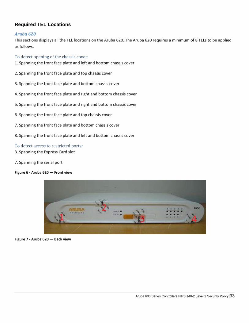
Required TEL Locations
Aruba620This sections displays all the TEL locations on the Aruba 620. The Aruba 620 requires a minimum of 8 TELs to be applied
as follows:
Todetectopeningofthechassiscover:1. Spanning the front face plate and left and bottom chassis cover
2. Spanning the front face plate and top chassis cover
3. Spanning the front face plate and bottom chassis cover
4. Spanning the front face plate and right and bottom chassis cover
5. Spanning the front face plate and right and bottom chassis cover
6. Spanning the front face plate and top chassis cover
7. Spanning the front face plate and bottom chassis cover
8. Spanning the front face plate and left and bottom chassis cover
Todetectaccesstorestrictedports:3. Spanning the Express Card slot
7. Spanning the serial port
Figure 6 ‐ Aruba 620 — Front view
Figure 7 ‐ Aruba 620 — Back view
34| Aruba 600 Series Controllers FIPS 140-2 Level 2 Security Policy
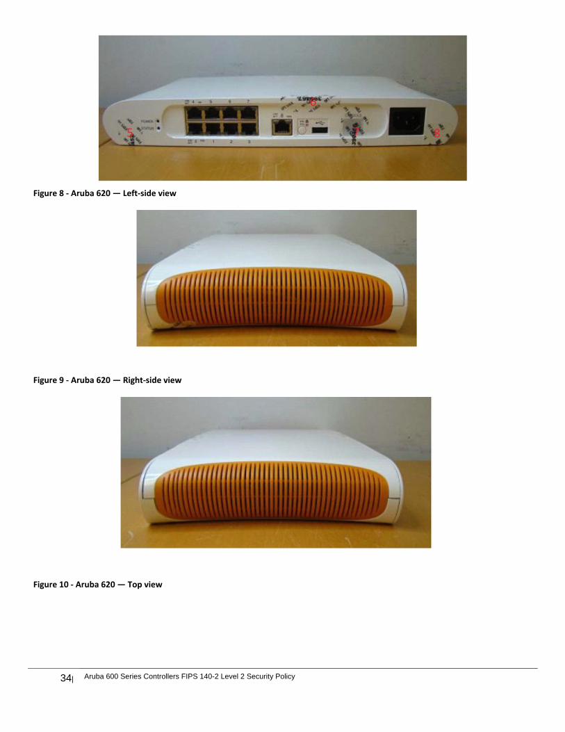
Figure 8 ‐ Aruba 620 — Left‐side view
Figure 9 ‐ Aruba 620 — Right‐side view
Figure 10 ‐ Aruba 620 — Top view
Aruba 600 Series Controllers FIPS 140-2 Level 2 Security Policy|35
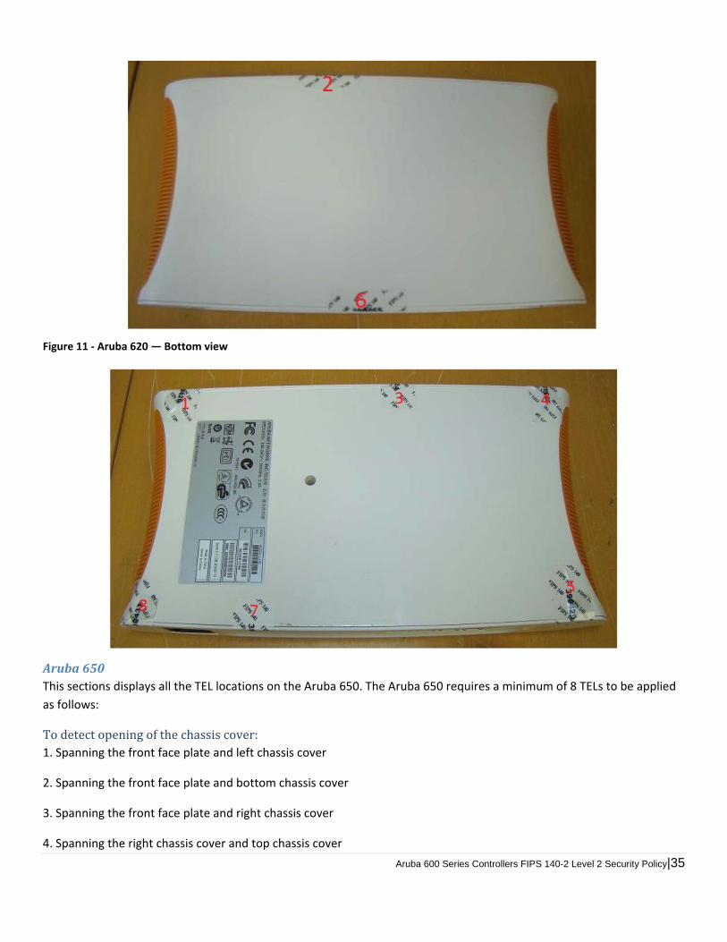
Figure 11 ‐ Aruba 620 — Bottom view
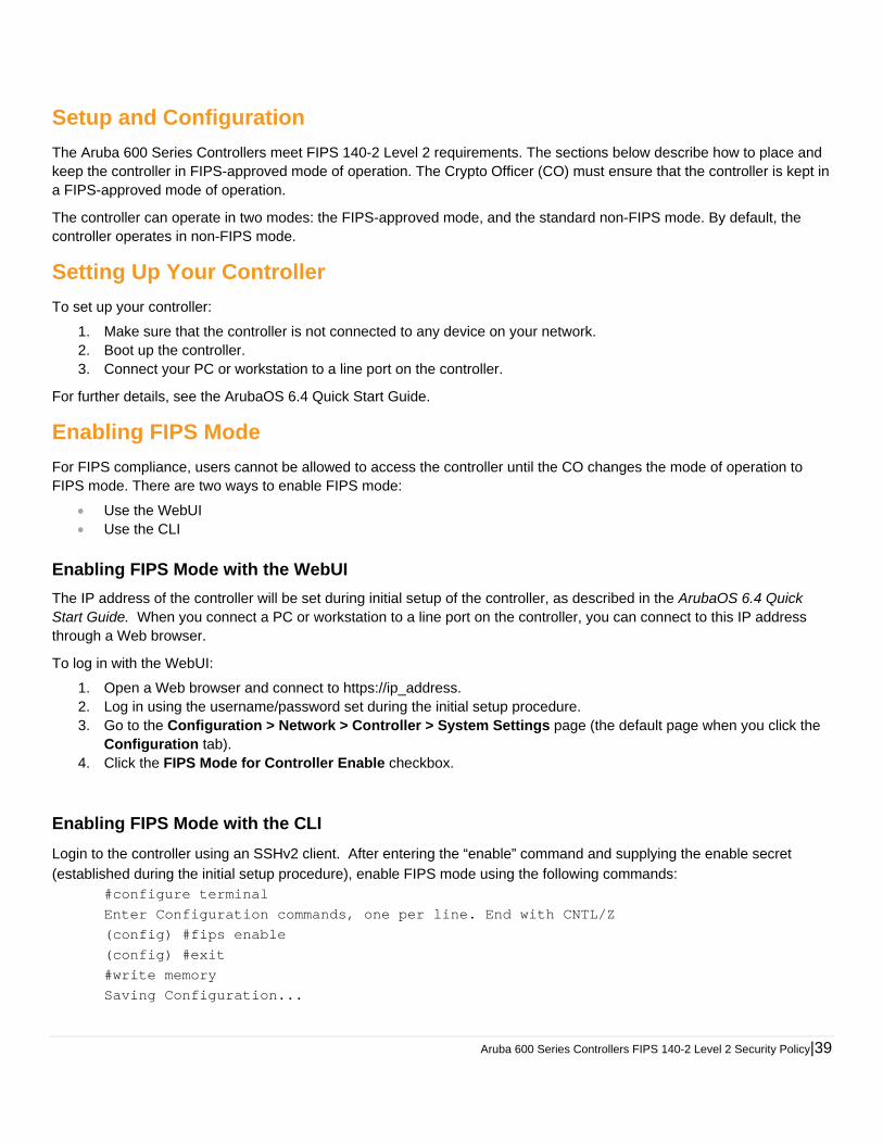
Aruba650This sections displays all the TEL locations on the Aruba 650. The Aruba 650 requires a minimum of 8 TELs to be applied
as follows:
Todetectopeningofthechassiscover:1. Spanning the front face plate and left chassis cover
2. Spanning the front face plate and bottom chassis cover
3. Spanning the front face plate and right chassis cover
4. Spanning the right chassis cover and top chassis cover
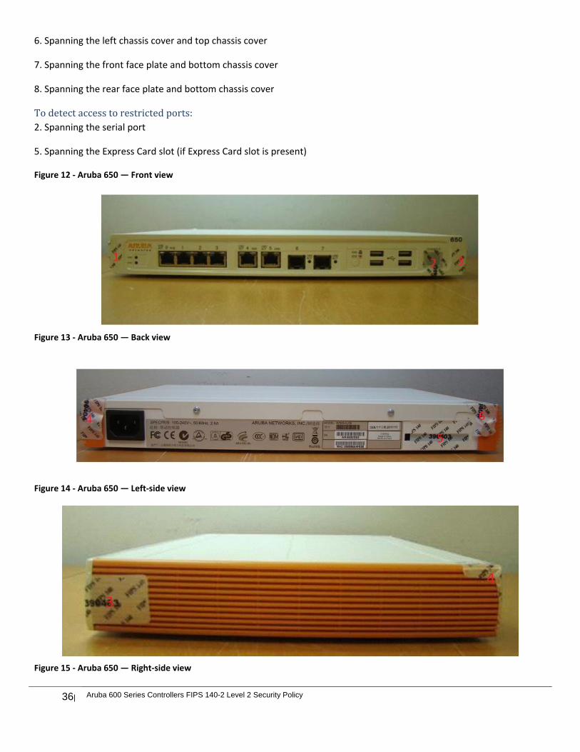
36| Aruba 600 Series Controllers FIPS 140-2 Level 2 Security Policy
6. Spanning the left chassis cover and top chassis cover
7. Spanning the front face plate and bottom chassis cover
8. Spanning the rear face plate and bottom chassis cover
Todetectaccesstorestrictedports:2. Spanning the serial port
5. Spanning the Express Card slot (if Express Card slot is present)
Figure 12 ‐ Aruba 650 — Front view
Figure 13 ‐ Aruba 650 — Back view
Figure 14 ‐ Aruba 650 — Left‐side view
Figure 15 ‐ Aruba 650 — Right‐side view
Aruba 600 Series Controllers FIPS 140-2 Level 2 Security Policy|37
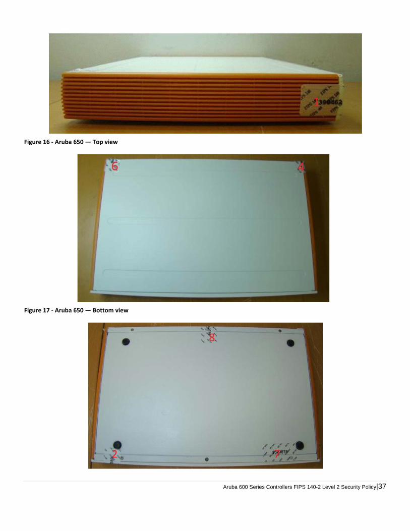
Figure 16 ‐ Aruba 650 — Top view
Figure 17 ‐ Aruba 650 — Bottom view

38| Aruba 600 Series Controllers FIPS 140-2 Level 2 Security Policy
Applying TELs
The Crypto Officer should employ TELs as follows:
Before applying a TEL, make sure the target surfaces are clean and dry. Do not cut, trim, punch, or otherwise alter the TEL. Apply the wholly intact TEL firmly and completely to the target surfaces. Press down firmly across the entire label surface, making several back-and-forth passes to ensure that the label
securely adheres to the chassis. Ensure that TEL placement is not defeated by simultaneous removal of multiple modules. Allow 24 hours for the TEL adhesive seal to completely cure. Record the position and serial number of each applied TEL in a security log.
Once the TELs are applied, the Crypto Officer (CO) should perform initial setup and configuration as described in the next chapter.
Ongoing Management
The Aruba 600 Series Controllers meet FIPS 140-2 Level 2 requirements. The information below describes how to keep the controller in FIPS-approved mode of operation. The Crypto Officer must ensure that the controller is kept in a FIPS-approved mode of operation.
Crypto Officer Management
The Crypto Officer must ensure that the controller is always operating in a FIPS-approved mode of operation. This can be achieved by ensuring the following:
FIPS mode must be enabled on the controller before Users are permitted to use the controller (see “Enabling FIPS Mode” in this document.)
The admin role must be root. Passwords must be at least six characters long. VPN services can only be provided by IPsec or L2TP over IPsec. Access to the controller Web Interface is permitted only using HTTPS over a TLS tunnel. Basic HTTP and HTTPS
over SSL are not permitted. Only SNMP read-only may be enabled. Only FIPS-approved algorithms can be used for cryptographic services (such as HTTPS, L2, AES-CBC, SSH, and
IKEv1/IKEv2-IPSec), which include AES, Triple-DES, SHA-1, HMAC SHA-1, and RSA signature and verification. TFTP can only be used to load backup and restore files. These files are: Configuration files (system setup
configuration), the WMS database (radio network configuration), and log files. (FTP and TFTP over IPsec can be used to transfer configuration files.)
The controller logs must be monitored. If a strange activity is found, the Crypto Officer should take the controller off line and investigate.
The Tamper-Evident Labels (TELs) must be regularly examined for signs of tampering. The Crypto Officer shall not configure the Diffie-Hellman algorithm with 768-bits (Group 1) in FIPS mode for
IKEv1/IKEv2-IPSec and SSHv2.
User Guidance
The User accesses the controller VPN functionality as an IPsec client. The user can also access the controller 802.11i functionality as an 802.11 client. Although outside the boundary of the controller, the User should be directed to be careful not to provide authentication information and session keys to others parties.
Aruba 600 Series Controllers FIPS 140-2 Level 2 Security Policy|39
Setup and Configuration
The Aruba 600 Series Controllers meet FIPS 140-2 Level 2 requirements. The sections below describe how to place and keep the controller in FIPS-approved mode of operation. The Crypto Officer (CO) must ensure that the controller is kept in a FIPS-approved mode of operation.
The controller can operate in two modes: the FIPS-approved mode, and the standard non-FIPS mode. By default, the controller operates in non-FIPS mode.
Setting Up Your Controller
To set up your controller:
1. Make sure that the controller is not connected to any device on your network. 2. Boot up the controller. 3. Connect your PC or workstation to a line port on the controller.
For further details, see the ArubaOS 6.4 Quick Start Guide.
Enabling FIPS Mode
For FIPS compliance, users cannot be allowed to access the controller until the CO changes the mode of operation to FIPS mode. There are two ways to enable FIPS mode:
Use the WebUI Use the CLI
Enabling FIPS Mode with the WebUI
The IP address of the controller will be set during initial setup of the controller, as described in the ArubaOS 6.4 Quick Start Guide. When you connect a PC or workstation to a line port on the controller, you can connect to this IP address through a Web browser.
To log in with the WebUI:
1. Open a Web browser and connect to https://ip_address. 2. Log in using the username/password set during the initial setup procedure. 3. Go to the Configuration > Network > Controller > System Settings page (the default page when you click the
Configuration tab). 4. Click the FIPS Mode for Controller Enable checkbox.
Enabling FIPS Mode with the CLI
Login to the controller using an SSHv2 client. After entering the “enable” command and supplying the enable secret
(established during the initial setup procedure), enable FIPS mode using the following commands: #configure terminal Enter Configuration commands, one per line. End with CNTL/Z (config) #fips enable (config) #exit #write memory Saving Configuration...

40| Aruba 600 Series Controllers FIPS 140-2 Level 2 Security Policy
Configuration Saved.
To verify that FIPS mode has been enabled, issue the command “show fips”.
Disallowed FIPS Mode Configurations
When you enable FIPS mode, the following configuration options are disallowed:
All WEP features WPA TKIP mixed mode Any combination of DES, MD5, and PPTP


![Aruba Networks - Cyber · [MIB] ArubaOS 6.x MIB Reference Guide, Ref 0511323-02 ... Aruba 7XXX Series Controllers FIPS 140-2 Security Policy . Aruba Networks Security Target Page](https://img.pdfslide.us/doc/110x75/5ea29c7c9d065e039132c51d/aruba-networks-cyber-mib-arubaos-6x-mib-reference-guide-ref-0511323-02-.jpg)