Embed Size (px)
Citation preview
FIPS 140-2 Non-Proprietary Security Policy for Aruba 2930F, 2930M, 3810M and 5400R zl2 Switch Series
Page 1 of 54
Aruba 2930F, 2930M, 3810M
and 5400R zl2 Switch Series FIPS 140-2 Non-Proprietary Security Policy
Security Level 1 Validation
Hardware: 2930F – Switches: JL258A, JL259A, JL260A, JL261A, JL262A, JL263A,
JL264A, JL557A, JL559A and JL692A
2930M – Switches: JL319A, JL320A, JL321A, JL322A, JL323A, JL324A, R0M67A and R0M68A; Expansion Cards: JL078A, JL081A and JL083A
3810M – Switches: JL071A, JL072A, JL073A, JL074A, JL075A and JL076A; Expansion Cards: JL078A, JL079A, JL081A and JL083A 5400R zl2 – Switch Chassis: 5406R zl2 J9821A and 5412R zl2 J9822A; Management Card: J9827A; Interface Cards: J9986A, J9987A, J9988A, J9989A, J9990A, J9991A, J9992A, J9993A, J9995A and J9996A
Firmware: 2930F – WC.16.08 2930M – WC.16. 08
3810M - KB.16. 08 5400R zl2- KB.16. 08
Version 4
December 1, 2020
FIPS 140-2 Non-Proprietary Security Policy for Aruba 2930F, 2930M, 3810M and 5400R zl2 Switch Series
Page 2 of 54
Disclaimer
The information contained in this document is subject to change without notice.
HEWLLETT PACKARD ENTERPRISE COMPANY MAKES NO WARRANTY OF ANY KIND WITH REGARD TO THIS
MATERIAL, INCLUDING, BUT NOT LIMITED TO, THE IMPLIED WARRANTIES OF MERCHANTABILITY AND
FITNESS FOR A PARTICULAR PURPOSE.
Hewlett Packard Enterprise (HPE) shall not be liable for errors contained herein or for incidental or
consequential damages in connection with the furnishing, performance, or use of this material.
The only warranties for HPE products and services are set forth in the express warranty statements
accompanying such products and services. Nothing herein should be constructed as constituting an
additional warranty. HPE shall not be liable for technical or editorial errors or omissions contained herein.
Hewlett Packard Enterprise assumes no responsibility for the use or reliability of its firmware on equipment
that is not furnished by Hewlett Packard Enterprise.
© Copyright 2020 Aruba Networks Inc.
This document may be freely reproduced and distributed whole and intact including this copyright notice.
Products identified herein contain confidential commercial firmware. Valid license required.
FIPS 140-2 Non-Proprietary Security Policy for Aruba 2930F, 2930M, 3810M and 5400R zl2 Switch Series
Page 3 of 54
Table of Contents
1 Introduction ................................................................................................................................ 8
Purpose .............................................................................................................................................. 8
References ......................................................................................................................................... 8
2 Overview..................................................................................................................................... 8
Configuration: .................................................................................................................................... 9
2930F Switch Series Configuration ............................................................................................ 9
2930M Switch Series Configuration......................................................................................... 10
3810M Switch Series Configuration......................................................................................... 11
5400R zl2 Switch Series Configuration .................................................................................... 12
Security Validation Level .................................................................................................................. 13
3 Cryptographic Module Specifications ......................................................................................... 13
Aruba 2930F Switch Series .............................................................................................................. 14
Aruba 2930M Switch Series ............................................................................................................. 16
Aruba 3810M Switch Series ............................................................................................................. 17
Aruba 5400R zl2 Switch Series ......................................................................................................... 19
4 Cryptographic Module Port and Interfaces ................................................................................. 20
Aruba 2930F Switch Series Ports ..................................................................................................... 20
Aruba 2390F Switch Series – Front Panel ................................................................................ 20
Aruba 2930M Switch Series - Back Panel ................................................................................ 22
Aruba 2930M Switch Series Ports.................................................................................................... 23
Aruba 2390M Switch Series – Front Panel............................................................................... 23
Aruba 2930M Switch Series - Back Panel ................................................................................ 24
Aruba 3810M Switch Series Ports.................................................................................................... 25
Aruba 3810M Switch Series – Front Panel............................................................................... 25
Aruba 3810M Switch Series - Back Panel ................................................................................ 26
Aruba 2930M and 3810M Switch Series – Expansion Cards ................................................... 27
Aruba 5400R zl2 Switch Series Ports ............................................................................................... 28
Aruba 5400R zl2 Switch Series – Front Panel .......................................................................... 28
Aruba 5400R zl2 Switch Series – Back Panel............................................................................ 30
Aruba 5400R zl2 Switch Series – Interface Cards .................................................................... 32
Aruba 2930F, 2930M, 3810M and 5400R zl2 Switch Series Ports and Interfaces ........................... 33
Console Port............................................................................................................................. 34
5 Roles, Services, and Authentication ............................................................................................ 35
Roles ................................................................................................................................................ 35
Services ............................................................................................................................................ 35
FIPS 140-2 Non-Proprietary Security Policy for Aruba 2930F, 2930M, 3810M and 5400R zl2 Switch Series
Page 4 of 54
Crypto Officer Services ............................................................................................................ 36
User Services ............................................................................................................................ 37
Security Officer Services .......................................................................................................... 38
Unauthenticated Services ........................................................................................................ 38
Non-Approved Services ........................................................................................................... 38
Authentication Mechanisms ............................................................................................................ 38
Authentication Data Protection ............................................................................................... 38
Identity-based Authentication ................................................................................................. 39
6 Physical Security Mechanism ..................................................................................................... 39
7 Cryptographic Algorithms .......................................................................................................... 40
FIPS Approved Cryptographic Algorithms ....................................................................................... 40
Notes:............................................................................................................................................... 41
FIPS Allowed Cryptographic Algorithms .......................................................................................... 41
Non-FIPS Approved / Allowed Cryptographic Algorithms ............................................................... 42
8 Cryptographic Key Management ................................................................................................ 43
Cryptographic Security Parameters ................................................................................................. 43
9 Self-Tests .................................................................................................................................. 45
Power-Up Self-Tests ........................................................................................................................ 45
BootROM Power-Up Self-Tests ................................................................................................ 46
Firmware Power-Up Self-Tests ................................................................................................ 46
Conditional Self-Tests ...................................................................................................................... 46
10 Delivery and Operation ............................................................................................................ 47
Secure Delivery ................................................................................................................................ 47
Secure Operation ............................................................................................................................. 47
Pre-Initialization ....................................................................................................................... 48
Initialization and Configuration ............................................................................................... 49
Zeroization ............................................................................................................................... 52
Secure Management........................................................................................................................ 53
User Management Access Guidance ............................................................................................... 53
BootROM Guidance ......................................................................................................................... 53
11 Mitigation of Other Attacks ..................................................................................................... 53
12 Documentation References ...................................................................................................... 54
Aruba Switch Series Documentation References ............................................................................ 54
Technical support ............................................................................................................................ 54
FIPS 140-2 Non-Proprietary Security Policy for Aruba 2930F, 2930M, 3810M and 5400R zl2 Switch Series
Page 5 of 54
TABLE OF TABLES and FIGURES Table 1 - List of abbreviations ............................................................................................................................ 7
Table 2 – 2930F Switch series configuration ..................................................................................................... 9
Table 3 - 2930M Switch series configuration .................................................................................................. 10
Table 4 - 3810M Switch series configuration .................................................................................................. 11
Table 5 - 5400R zl2 Switch series configuration .............................................................................................. 12
Table 6 - Validation Level by Section ............................................................................................................... 13
Table 7 - 2930F Switch Series .......................................................................................................................... 15
Table 8 - 2930M Switch Series ......................................................................................................................... 16
Table 9 - 3810M Switch series ......................................................................................................................... 18
Table 10 – Front of the 2930F Switch Labels and Descriptions ....................................................................... 21
Table 11 - Back of the 2930F Switch labels and descriptions .......................................................................... 22
Table 12 – Front of the 2930M Switch Labels and Descriptions ..................................................................... 23
Table 13 - Back of the 2930M Switch labels and descriptions......................................................................... 24
Table 14 - Front of the 3810M switch labels and descriptions ........................................................................ 25
Table 15 - Back of the 3810M switch labels and description .......................................................................... 26
Table 16- 2930M/3810M Expansion Card label and Description .................................................................... 27
Table 17 - Front of 5400R zl2 switch series ..................................................................................................... 28
Table 18 – BACK PANEL of 5400R zl2 SWITCH SERIES ..................................................................................... 31
Table 19- 5400R zl2 Interface Cards ................................................................................................................ 33
Table 20 - Logical and Physical Interfaces ....................................................................................................... 33
Table 21 - Crypto officer services .................................................................................................................... 36
Table 22 - User services ................................................................................................................................... 37
Table 23 - Security Officer Services ................................................................................................................. 38
Table 24 - FIPS-Approved Cryptography Algorithms ....................................................................................... 40
FIPS 140-2 Non-Proprietary Security Policy for Aruba 2930F, 2930M, 3810M and 5400R zl2 Switch Series
Page 6 of 54
Table 25 - FIPS-Allowed Cryptography Algorithms .......................................................................................... 41
Table 26 - Non-FIPS Approved Cryptography Algorithms................................................................................ 42
Table 27 - Cryptographic Security Parameters ................................................................................................ 43
Figure 1 - 2930F Switch Series ......................................................................................................................... 14
Figure 2 - 2930M Switch Series........................................................................................................................ 16
Figure 3- 3810M Switch Series ........................................................................................................................ 18
Figure 4 - 5406R zl2 switch series .................................................................................................................... 19
Figure 5 - 5412R zl2 switch series .................................................................................................................... 19
Figure 6 - Example of Front of the 2930F Switch ............................................................................................. 20
Figure 7 - Back of the 24 and 48 port 2930F Switches .................................................................................... 22
Figure 8 - Example of Front of the 2930M Switch ........................................................................................... 23
Figure 9 - Back of the 2930M Switches............................................................................................................ 24
Figure 10 -Front panel of 3810m switch series ............................................................................................... 25
Figure 11 - Back of the 3810m switch series ................................................................................................... 26
Figure 12 - Front of 2930M/3810M expansion Cards ..................................................................................... 27
Figure 13 - Front of 5400R zl2 switch series .................................................................................................... 28
Figure 14 - Back of 5406r zl2 switch series with one power supply ................................................................ 30
Figure 15 - Back of 5412R zl2 switch series with two power supply ............................................................... 30
Figure 16 - 5400R zl2 Interface Cards .............................................................................................................. 32
FIPS 140-2 Non-Proprietary Security Policy for Aruba 2930F, 2930M, 3810M and 5400R zl2 Switch Series
Page 7 of 54
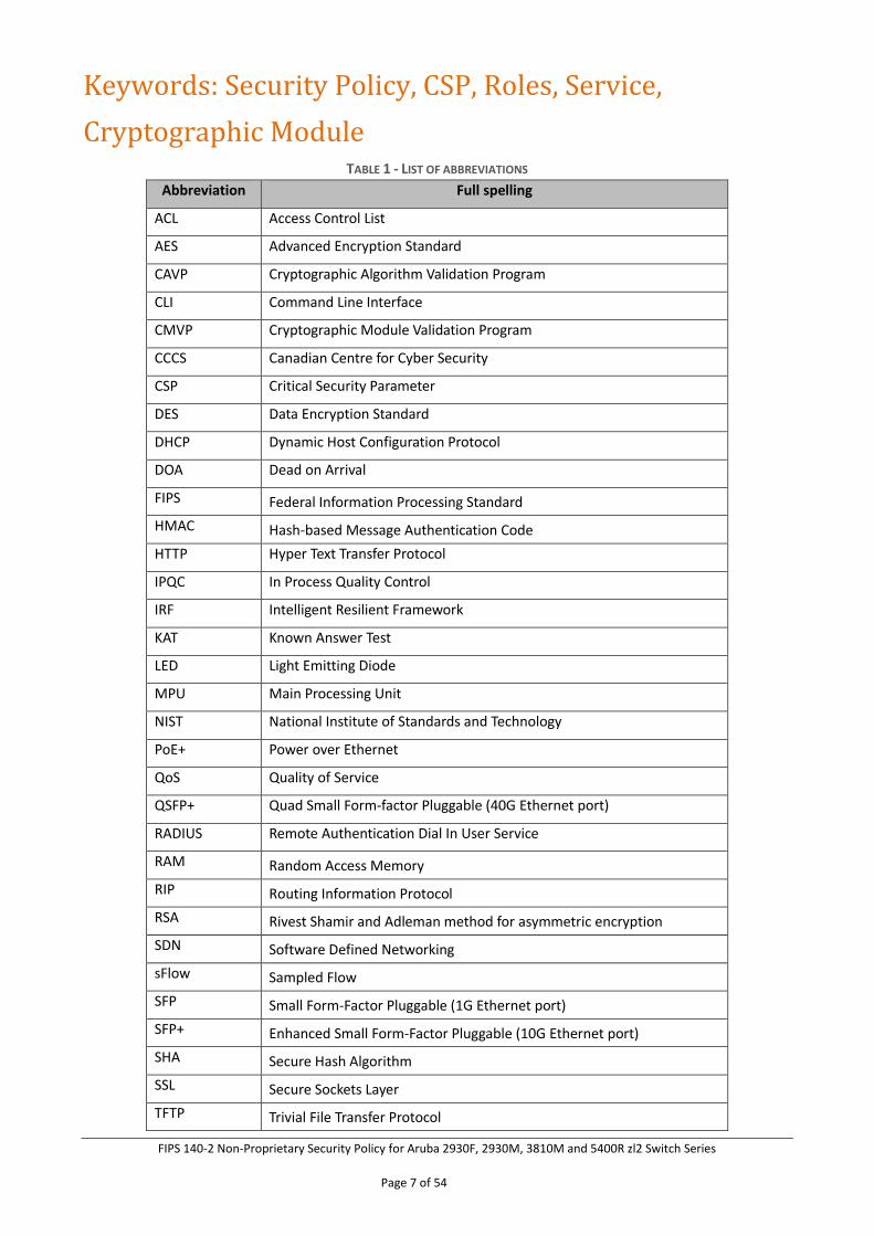
Keywords: Security Policy, CSP, Roles, Service,
Cryptographic Module TABLE 1 - LIST OF ABBREVIATIONS
Abbreviation Full spelling
ACL Access Control List
AES Advanced Encryption Standard
CAVP Cryptographic Algorithm Validation Program
CLI Command Line Interface
CMVP Cryptographic Module Validation Program
CCCS Canadian Centre for Cyber Security
CSP Critical Security Parameter
DES Data Encryption Standard
DHCP Dynamic Host Configuration Protocol
DOA Dead on Arrival
FIPS Federal Information Processing Standard
HMAC Hash-based Message Authentication Code
HTTP Hyper Text Transfer Protocol
IPQC In Process Quality Control
IRF Intelligent Resilient Framework
KAT Known Answer Test
LED Light Emitting Diode
MPU Main Processing Unit
NIST National Institute of Standards and Technology
PoE+ Power over Ethernet
QoS Quality of Service
QSFP+ Quad Small Form-factor Pluggable (40G Ethernet port)
RADIUS Remote Authentication Dial In User Service
RAM Random Access Memory
RIP Routing Information Protocol
RSA Rivest Shamir and Adleman method for asymmetric encryption
SDN Software Defined Networking
sFlow Sampled Flow
SFP Small Form-Factor Pluggable (1G Ethernet port)
SFP+ Enhanced Small Form-Factor Pluggable (10G Ethernet port)
SHA Secure Hash Algorithm
SSL Secure Sockets Layer
TFTP Trivial File Transfer Protocol
FIPS 140-2 Non-Proprietary Security Policy for Aruba 2930F, 2930M, 3810M and 5400R zl2 Switch Series
Page 8 of 54
1 Introduction
Purpose
This is a non-proprietary Cryptographic Module Security Policy for the Aruba 2930F, 2930M, 3810M and 5400R zl2 Switch Series from Aruba, a Hewlett Packard
Enterprise (HPE) Company. This Security Policy describes how the Aruba 2930F, 2930M, 3810M and 5400R zl2 Switch Series meet the security requirements of Federal
Information Processing Standards (FIPS) Publication 140-2, which details the U.S. and Canadian Government requirements for cryptographic modules. More information
about the FIPS 140-2 standard and validation program is available on the National Institute of Standards and Technology (NIST) and the Canadian Centre for Cyber
Security (CCCS) Cryptographic Module Validation Program (CMVP) websites at https://csrc.nist.gov/projects/cryptographic-module-validation-program and
https://cyber.gc.ca/en/ respectively.
This document also describes how to run the module in a secure FIPS-Approved mode of operation. This policy was prepared as part of the Overall Level 1 FIPS 140-2
validation of the module. The Aruba 2930F, 2930M, 3810M and 5400R zl2 Switch Series are referred to in this document as Aruba 2930F, 2930M, 3810M and 5400R zl2
Switch Series, the switches, the cryptographic module, or the module.
References
This document deals only with operations and capabilities of the module in the technical terms of a FIPS 140-2 cryptographic module security policy. More information
is available on the module from the following sources:
• The HPE website (www.hpe.com) and Aruba website (www.arubanetworks.com) contain information on the full line of products for Aruba.
• The CMVP website (https://csrc.nist.gov/projects/cryptographic-module-validation-program/validated-modules/search) contains contact information for
individuals to answer technical or sales-related questions for the module.
2 Overview
The Aruba 2930F and 2930M Switch Series are designed for customers creating digital workplaces that are optimized for mobile users with an integrated wired and wireless
approach. These Layer 3 access switches come with high performance modular stacking for up to 10 switches. The 2930M supports 10GbE and 40GbE uplinks, Dual
FIPS 140-2 Non-Proprietary Security Policy for Aruba 2930F, 2930M, 3810M and 5400R zl2 Switch Series
Page 9 of 54
Modular Power Supplies, up to 1440 Watts of PoE+, HPE Smart Rate, robust QoS, RIP, Access OSPF routing, Tunnel Node, PIM, VRRP and IPv6. The 2930F supports 10GbE
uplinks, PoE+, robust QoS, RIP Routing, Access OSPF, ACLs, and IPV6. The module delivers consistent user experience with unified management tools. It comes with built-in
1GbE or 10GbE uplinks and up to 370W PoE+.
The Aruba 3810M Switch Series is an industry-leading mobile campus access solution for enterprises, SMBs, and branch office networks. This Aruba Layer 3 switch series
comes with backplane stacking, low latency and resiliency and HPE Smart Rate for high-speed multi-gigabit capacity and PoE+ power, modular line rate 10GbE and 40GbE
ports for wireless aggregation, full PoE+ on all ports for high-speed wireless APs.
The Aruba 5400R zl2 Switch Series is an industry-leading mobile campus access solution with HPE Smart Rate multi-gigabit ports for high-speed connectivity and bandwidth
for next wave 802.11ac devices. Robust solutions, hitless failover, QoS, and security with full L3 features and flexible connectivity including 40 Gigabit Ethernet ports and
full PoE+, the Aruba 5400R zl2 requires no add-on firmware licensing. The Aruba 5400R zl2 Switch Series is suitable for a range of uses. These switches can be deployed at
enterprise edge and remote branch offices, and converged networks.
Each device is based on the Aruba OS Firmware platform:
• 2930F – Version WC.16.08
• 2930M – Version WC.16.08
• 3810M – Version KB.16.08
• 5400R zl2 – Version KB.16.08
The modules are being validated as a multi-chip standalone network device at FIPS 140-2 Overall Security Level 1.
Configuration:
The Switches included as part of the FIPS 140-2 validation may be configured as follows:
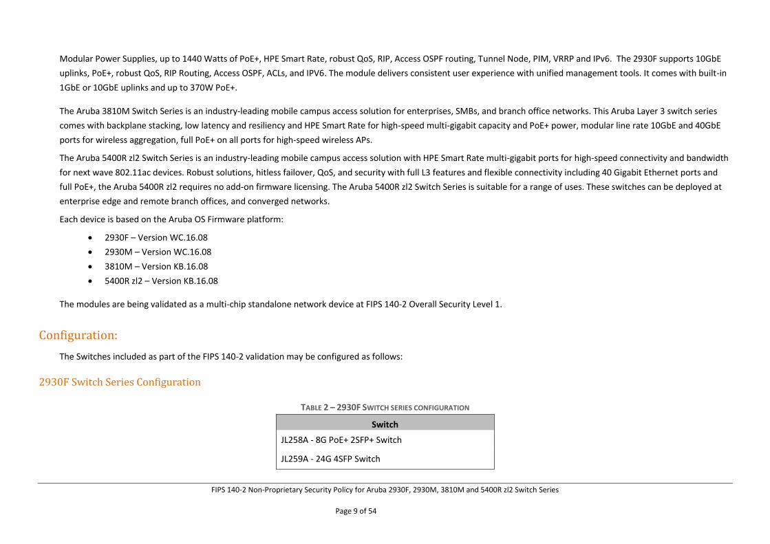
2930F Switch Series Configuration
TABLE 2 – 2930F SWITCH SERIES CONFIGURATION
Switch
JL258A - 8G PoE+ 2SFP+ Switch
JL259A - 24G 4SFP Switch
FIPS 140-2 Non-Proprietary Security Policy for Aruba 2930F, 2930M, 3810M and 5400R zl2 Switch Series
Page 10 of 54
JL260A - 48G 4SFP Switch
JL261A - 24G PoE+ 4SFP Switch
JL262A - 48G PoE+ 4SFP Switch
JL263A- 24G PoE+ 4SFP+ Switch
JL264A – 48G PoE+ 4SFP+ Switch
JL557A - 48G PoE+ 4SFP 740W Switch
JL559A – 48G PoE+ 4SFP+ 740W Switch
JL692A - 8G PoE+ 2SFP+ Switch
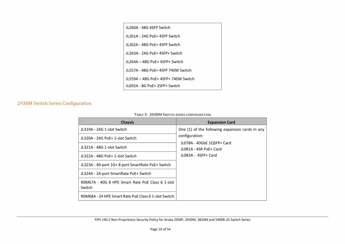
2930M Switch Series Configuration
TABLE 3 - 2930M SWITCH SERIES CONFIGURATION
Chassis Expansion Card
JL319A - 24G 1-slot Switch One (1) of the following expansion cards in any
configuration:
JL078A - 40GbE 1QSFP+ Card
JL081A - 4SR PoE+ Card
JL083A - 4SFP+ Card
JL320A - 24G PoE+ 1-slot Switch
JL321A - 48G 1-slot Switch
JL322A - 48G PoE+ 1-slot Switch
JL323A - 40-port 1G+ 8 port SmartRate PoE+ Switch
JL324A - 24-port SmartRate PoE+ Switch
R0M67A - 40G 8 HPE Smart Rate PoE Class 6 1-slot Switch
R0M68A - 24 HPE Smart Rate PoE Class 6 1-slot Switch
FIPS 140-2 Non-Proprietary Security Policy for Aruba 2930F, 2930M, 3810M and 5400R zl2 Switch Series
Page 11 of 54
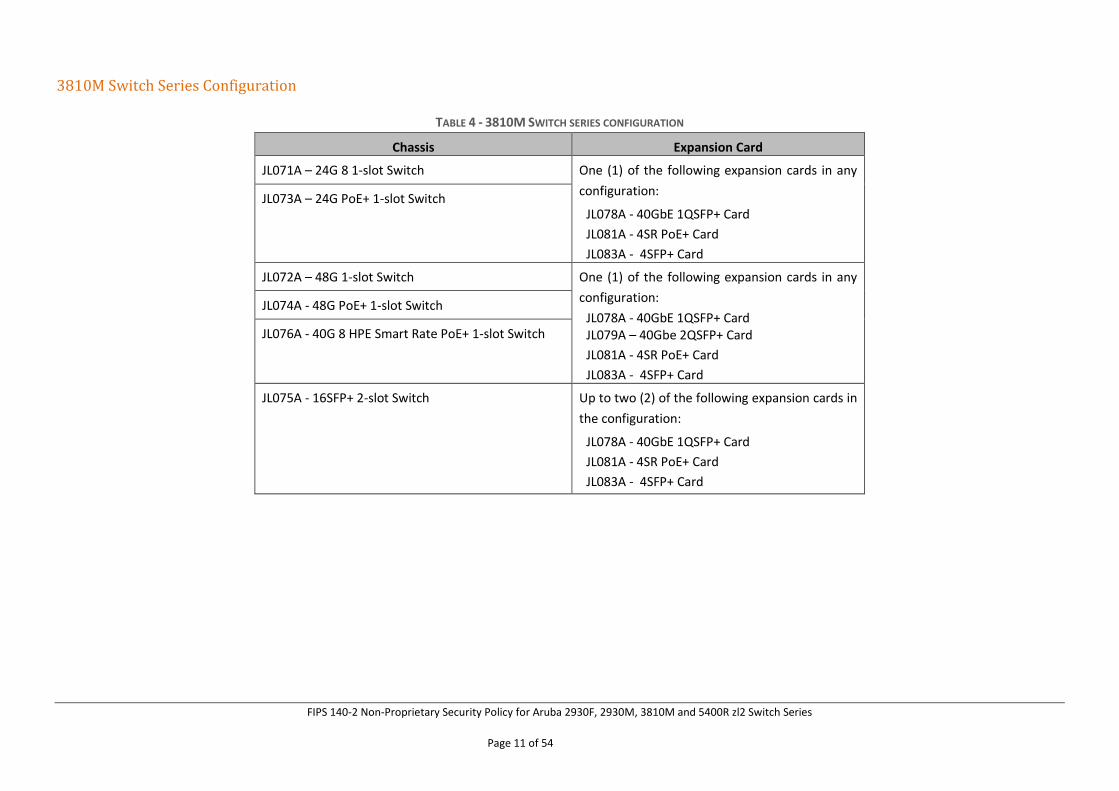
3810M Switch Series Configuration
TABLE 4 - 3810M SWITCH SERIES CONFIGURATION
Chassis Expansion Card
JL071A – 24G 8 1-slot Switch One (1) of the following expansion cards in any
configuration:
JL078A - 40GbE 1QSFP+ Card
JL081A - 4SR PoE+ Card
JL083A - 4SFP+ Card
JL073A – 24G PoE+ 1-slot Switch
JL072A – 48G 1-slot Switch One (1) of the following expansion cards in any
configuration:
JL078A - 40GbE 1QSFP+ Card JL079A – 40Gbe 2QSFP+ Card
JL081A - 4SR PoE+ Card
JL083A - 4SFP+ Card
JL074A - 48G PoE+ 1-slot Switch
JL076A - 40G 8 HPE Smart Rate PoE+ 1-slot Switch
JL075A - 16SFP+ 2-slot Switch Up to two (2) of the following expansion cards in
the configuration:
JL078A - 40GbE 1QSFP+ Card
JL081A - 4SR PoE+ Card
JL083A - 4SFP+ Card
FIPS 140-2 Non-Proprietary Security Policy for Aruba 2930F, 2930M, 3810M and 5400R zl2 Switch Series
Page 12 of 54
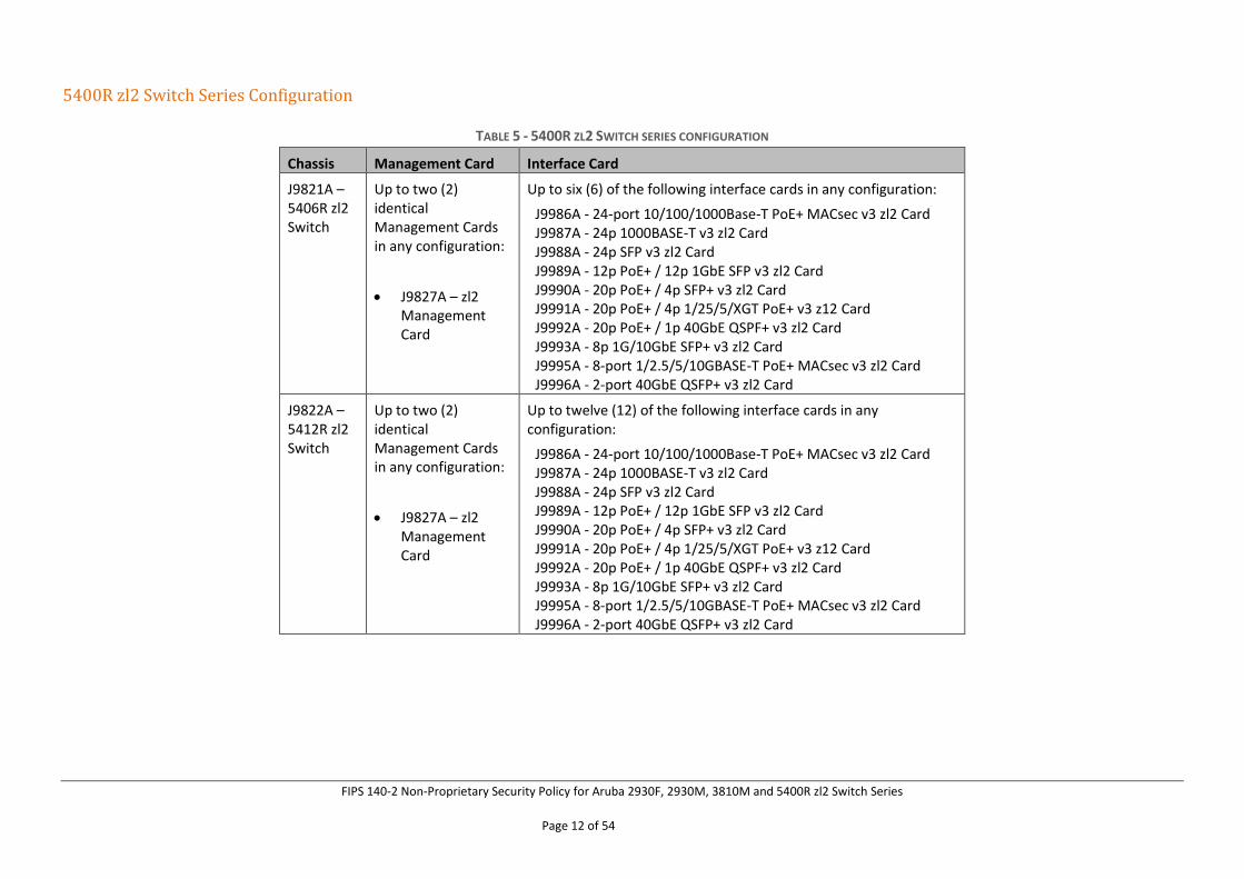
5400R zl2 Switch Series Configuration
TABLE 5 - 5400R ZL2 SWITCH SERIES CONFIGURATION
Chassis Management Card Interface Card
J9821A – 5406R zl2 Switch
Up to two (2) identical Management Cards in any configuration:
• J9827A – zl2 Management Card
Up to six (6) of the following interface cards in any configuration:
J9986A - 24-port 10/100/1000Base-T PoE+ MACsec v3 zl2 Card J9987A - 24p 1000BASE-T v3 zl2 Card J9988A - 24p SFP v3 zl2 Card J9989A - 12p PoE+ / 12p 1GbE SFP v3 zl2 Card J9990A - 20p PoE+ / 4p SFP+ v3 zl2 Card J9991A - 20p PoE+ / 4p 1/25/5/XGT PoE+ v3 z12 Card J9992A - 20p PoE+ / 1p 40GbE QSPF+ v3 zl2 Card J9993A - 8p 1G/10GbE SFP+ v3 zl2 Card J9995A - 8-port 1/2.5/5/10GBASE-T PoE+ MACsec v3 zl2 Card J9996A - 2-port 40GbE QSFP+ v3 zl2 Card
J9822A – 5412R zl2 Switch
Up to two (2) identical Management Cards in any configuration:
• J9827A – zl2 Management Card
Up to twelve (12) of the following interface cards in any configuration:
J9986A - 24-port 10/100/1000Base-T PoE+ MACsec v3 zl2 Card J9987A - 24p 1000BASE-T v3 zl2 Card J9988A - 24p SFP v3 zl2 Card J9989A - 12p PoE+ / 12p 1GbE SFP v3 zl2 Card J9990A - 20p PoE+ / 4p SFP+ v3 zl2 Card J9991A - 20p PoE+ / 4p 1/25/5/XGT PoE+ v3 z12 Card J9992A - 20p PoE+ / 1p 40GbE QSPF+ v3 zl2 Card J9993A - 8p 1G/10GbE SFP+ v3 zl2 Card J9995A - 8-port 1/2.5/5/10GBASE-T PoE+ MACsec v3 zl2 Card J9996A - 2-port 40GbE QSFP+ v3 zl2 Card
FIPS 140-2 Non-Proprietary Security Policy for Aruba 2930F, 2930M, 3810M and 5400R zl2 Switch Series
Page 13 of 54
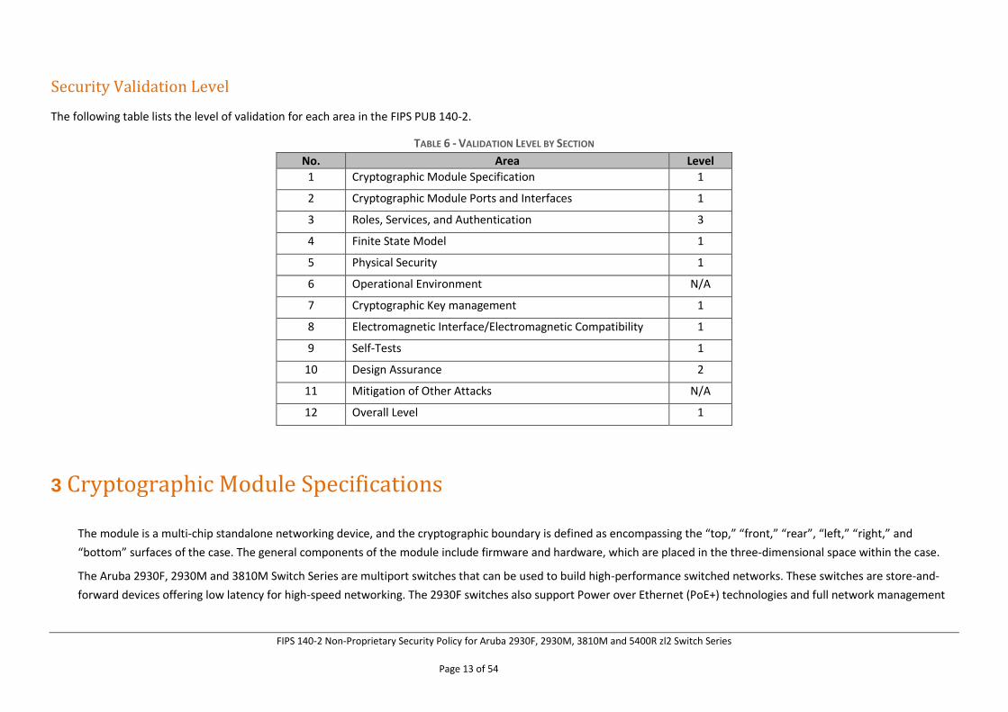
Security Validation Level
The following table lists the level of validation for each area in the FIPS PUB 140-2.
TABLE 6 - VALIDATION LEVEL BY SECTION
No. Area Level
1 Cryptographic Module Specification 1
2 Cryptographic Module Ports and Interfaces 1
3 Roles, Services, and Authentication 3
4 Finite State Model 1
5 Physical Security 1
6 Operational Environment N/A
7 Cryptographic Key management 1
8 Electromagnetic Interface/Electromagnetic Compatibility 1
9 Self-Tests 1
10 Design Assurance 2
11 Mitigation of Other Attacks N/A
12 Overall Level 1
3 Cryptographic Module Specifications
The module is a multi-chip standalone networking device, and the cryptographic boundary is defined as encompassing the “top,” “front,” “rear”, “left,” “right,” and
“bottom” surfaces of the case. The general components of the module include firmware and hardware, which are placed in the three-dimensional space within the case.
The Aruba 2930F, 2930M and 3810M Switch Series are multiport switches that can be used to build high-performance switched networks. These switches are store-and-
forward devices offering low latency for high-speed networking. The 2930F switches also support Power over Ethernet (PoE+) technologies and full network management
FIPS 140-2 Non-Proprietary Security Policy for Aruba 2930F, 2930M, 3810M and 5400R zl2 Switch Series
Page 14 of 54
capabilities. The Aruba 2930M and 3810M switches also support a field-replaceable Redundant Power Supply and fan tray, Power over Ethernet (PoE+) technologies, full
network management capabilities and a flexible uplink port slot (refer to Tables 3 and 4 for interface cards for each module).
The Aruba 5400R zl2 Switch offers power and management redundancy in a modular 6-slot or 12-slot chassis supporting interface cards providing 1GbE, 10GbE and 40GbE
ports, multi-gigabit HPE Smart Rate ports, and full PoE+ (refer to Table 5 for list of interface cards).
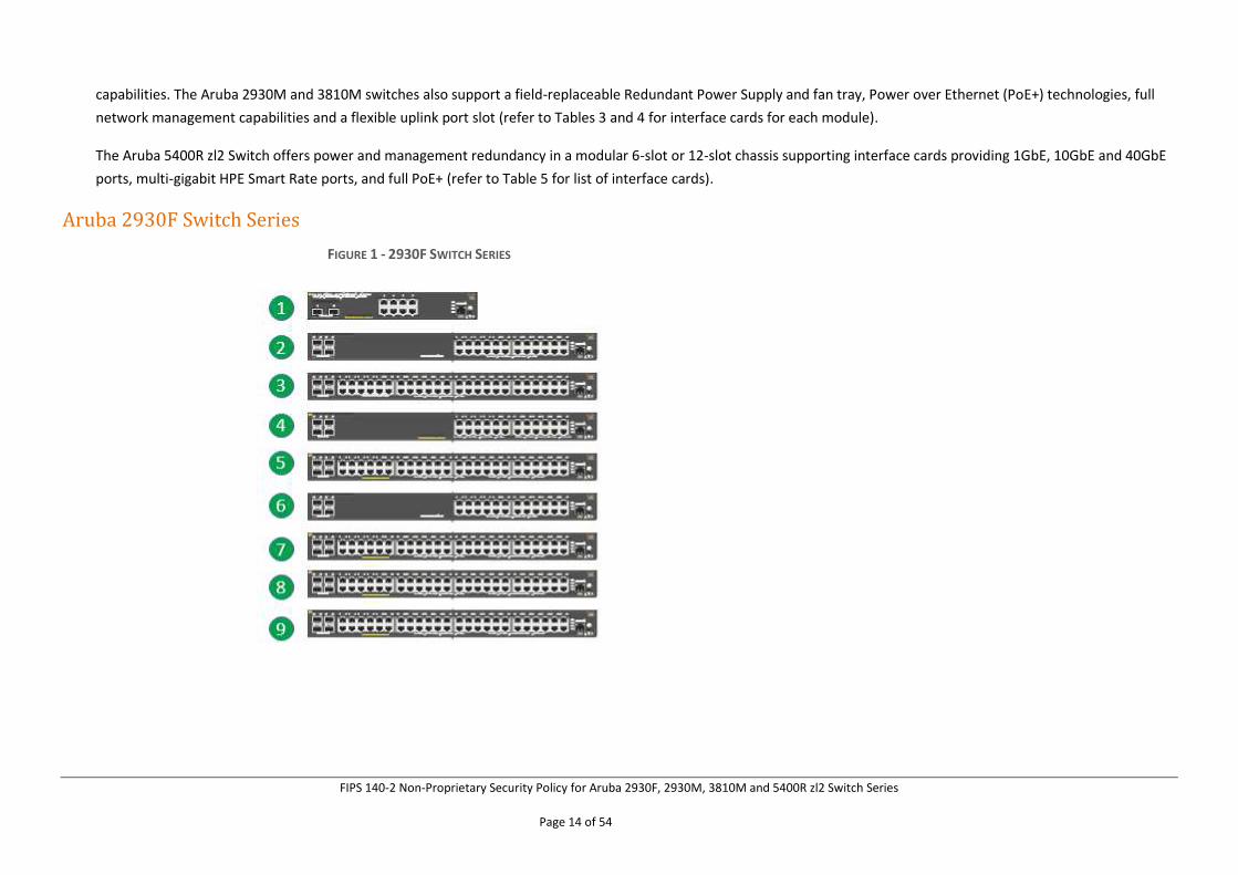
Aruba 2930F Switch Series
FIGURE 1 - 2930F SWITCH SERIES
FIPS 140-2 Non-Proprietary Security Policy for Aruba 2930F, 2930M, 3810M and 5400R zl2 Switch Series
Page 15 of 54
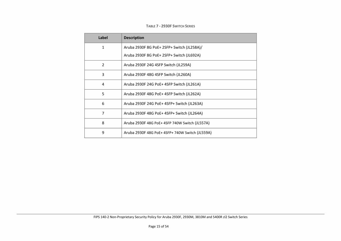
TABLE 7 - 2930F SWITCH SERIES
Label Description
1 Aruba 2930F 8G PoE+ 2SFP+ Switch (JL258A)/
Aruba 2930F 8G PoE+ 2SFP+ Switch (JL692A)
2 Aruba 2930F 24G 4SFP Switch (JL259A)
3 Aruba 2930F 48G 4SFP Switch (JL260A)
4 Aruba 2930F 24G PoE+ 4SFP Switch (JL261A)
5 Aruba 2930F 48G PoE+ 4SFP Switch (JL262A)
6 Aruba 2930F 24G PoE+ 4SFP+ Switch (JL263A)
7 Aruba 2930F 48G PoE+ 4SFP+ Switch (JL264A)
8 Aruba 2930F 48G PoE+ 4SFP 740W Switch (JL557A)
9 Aruba 2930F 48G PoE+ 4SFP+ 740W Switch (JL559A)
FIPS 140-2 Non-Proprietary Security Policy for Aruba 2930F, 2930M, 3810M and 5400R zl2 Switch Series
Page 16 of 54
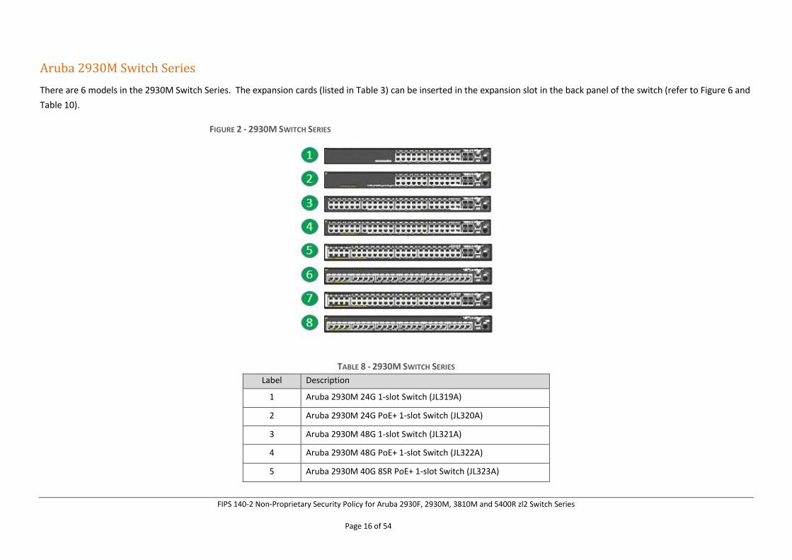
Aruba 2930M Switch Series
There are 6 models in the 2930M Switch Series. The expansion cards (listed in Table 3) can be inserted in the expansion slot in the back panel of the switch (refer to Figure 6 and
Table 10).
FIGURE 2 - 2930M SWITCH SERIES
TABLE 8 - 2930M SWITCH SERIES
Label Description
1 Aruba 2930M 24G 1-slot Switch (JL319A)
2 Aruba 2930M 24G PoE+ 1-slot Switch (JL320A)
3 Aruba 2930M 48G 1-slot Switch (JL321A)
4 Aruba 2930M 48G PoE+ 1-slot Switch (JL322A)
5 Aruba 2930M 40G 8SR PoE+ 1-slot Switch (JL323A)
FIPS 140-2 Non-Proprietary Security Policy for Aruba 2930F, 2930M, 3810M and 5400R zl2 Switch Series
Page 17 of 54
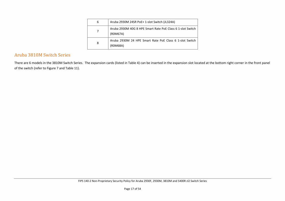
6 Aruba 2930M 24SR PoE+ 1-slot Switch (JL324A)
7 Aruba 2930M 40G 8 HPE Smart Rate PoE Class 6 1-slot Switch
(R0M67A)
8 Aruba 2930M 24 HPE Smart Rate PoE Class 6 1-slot Switch
(R0M68A)
Aruba 3810M Switch Series
There are 6 models in the 3810M Switch Series. The expansion cards (listed in Table 4) can be inserted in the expansion slot located at the bottom right corner in the front panel
of the switch (refer to Figure 7 and Table 11).
FIPS 140-2 Non-Proprietary Security Policy for Aruba 2930F, 2930M, 3810M and 5400R zl2 Switch Series
Page 18 of 54
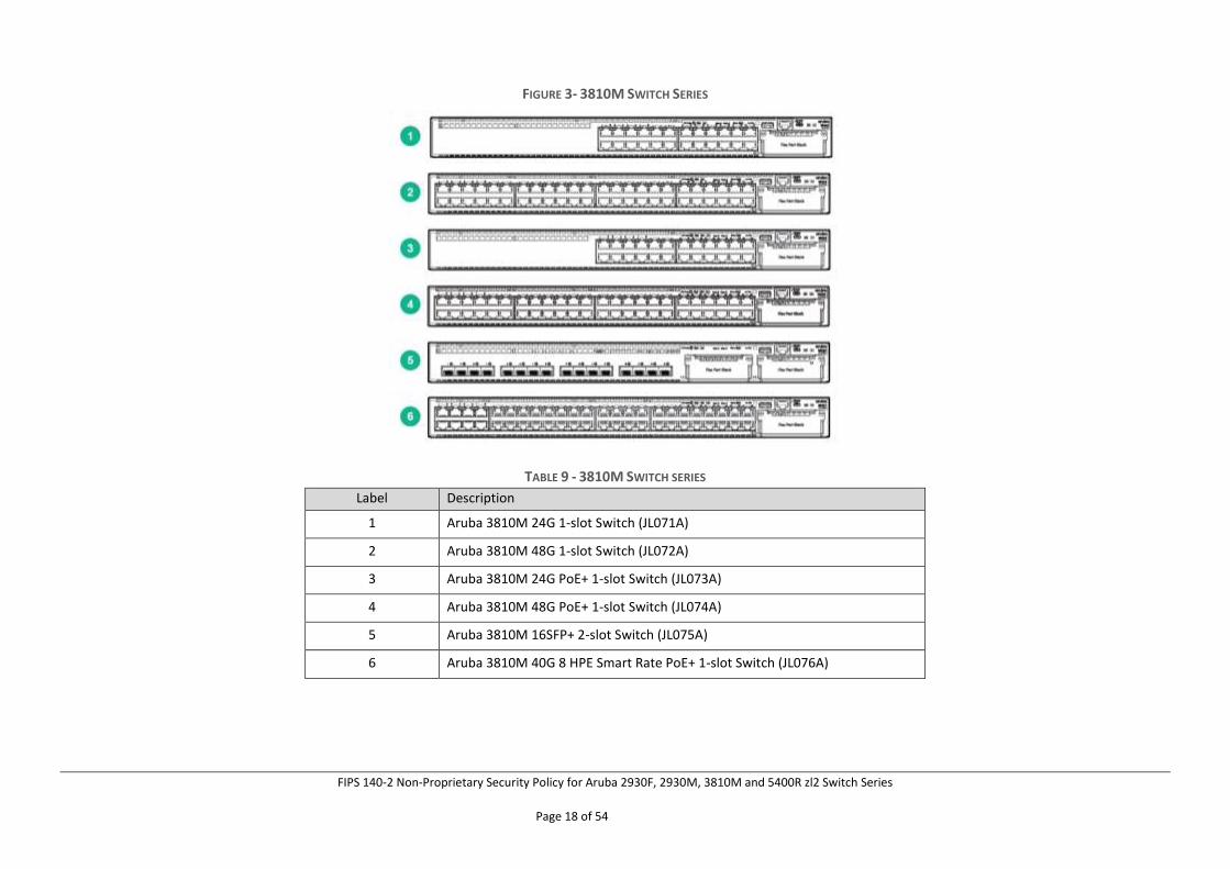
FIGURE 3- 3810M SWITCH SERIES
TABLE 9 - 3810M SWITCH SERIES
Label Description
1 Aruba 3810M 24G 1-slot Switch (JL071A)
2 Aruba 3810M 48G 1-slot Switch (JL072A)
3 Aruba 3810M 24G PoE+ 1-slot Switch (JL073A)
4 Aruba 3810M 48G PoE+ 1-slot Switch (JL074A)
5 Aruba 3810M 16SFP+ 2-slot Switch (JL075A)
6 Aruba 3810M 40G 8 HPE Smart Rate PoE+ 1-slot Switch (JL076A)
FIPS 140-2 Non-Proprietary Security Policy for Aruba 2930F, 2930M, 3810M and 5400R zl2 Switch Series
Page 19 of 54
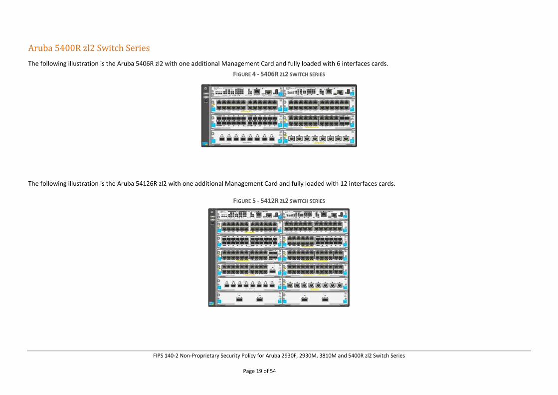
Aruba 5400R zl2 Switch Series
The following illustration is the Aruba 5406R zl2 with one additional Management Card and fully loaded with 6 interfaces cards.
FIGURE 4 - 5406R ZL2 SWITCH SERIES
The following illustration is the Aruba 54126R zl2 with one additional Management Card and fully loaded with 12 interfaces cards.
FIGURE 5 - 5412R ZL2 SWITCH SERIES
FIPS 140-2 Non-Proprietary Security Policy for Aruba 2930F, 2930M, 3810M and 5400R zl2 Switch Series
Page 20 of 54
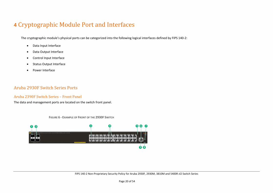
4 Cryptographic Module Port and Interfaces
The cryptographic module’s physical ports can be categorized into the following logical interfaces defined by FIPS 140-2:
• Data Input Interface
• Data Output Interface
• Control Input Interface
• Status Output Interface
• Power Interface
Aruba 2930F Switch Series Ports
Aruba 2390F Switch Series – Front Panel
The data and management ports are located on the switch front panel.
FIGURE 6 - EXAMPLE OF FRONT OF THE 2930F SWITCH
FIPS 140-2 Non-Proprietary Security Policy for Aruba 2930F, 2930M, 3810M and 5400R zl2 Switch Series
Page 21 of 54
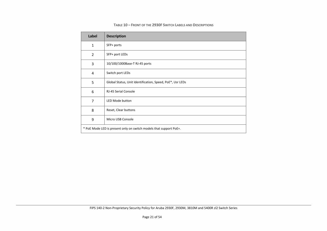
TABLE 10 – FRONT OF THE 2930F SWITCH LABELS AND DESCRIPTIONS
Label Description
1 SFP+ ports
2 SFP+ port LEDs
3 10/100/1000Base-T RJ-45 ports
4 Switch port LEDs
5 Global Status, Unit Identification, Speed, PoE*, Usr LEDs
6 RJ-45 Serial Console
7 LED Mode button
8 Reset, Clear buttons
9 Micro USB Console
* PoE Mode LED is present only on switch models that support PoE+.
FIPS 140-2 Non-Proprietary Security Policy for Aruba 2930F, 2930M, 3810M and 5400R zl2 Switch Series
Page 22 of 54
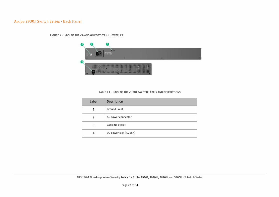
Aruba 2930F Switch Series - Back Panel
FIGURE 7 - BACK OF THE 24 AND 48 PORT 2930F SWITCHES
TABLE 11 - BACK OF THE 2930F SWITCH LABELS AND DESCRIPTIONS
Label Description
1 Ground Point
2 AC power connector
3 Cable tie eyelet
4 DC power jack (JL258A)
FIPS 140-2 Non-Proprietary Security Policy for Aruba 2930F, 2930M, 3810M and 5400R zl2 Switch Series
Page 23 of 54
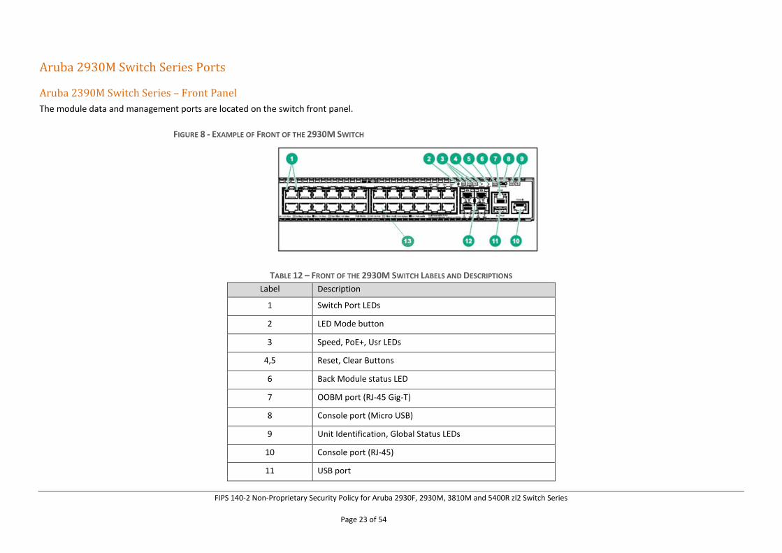
Aruba 2930M Switch Series Ports
Aruba 2390M Switch Series – Front Panel
The module data and management ports are located on the switch front panel.
FIGURE 8 - EXAMPLE OF FRONT OF THE 2930M SWITCH
TABLE 12 – FRONT OF THE 2930M SWITCH LABELS AND DESCRIPTIONS
Label Description
1 Switch Port LEDs
2 LED Mode button
3 Speed, PoE+, Usr LEDs
4,5 Reset, Clear Buttons
6 Back Module status LED
7 OOBM port (RJ-45 Gig-T)
8 Console port (Micro USB)
9 Unit Identification, Global Status LEDs
10 Console port (RJ-45)
11 USB port
FIPS 140-2 Non-Proprietary Security Policy for Aruba 2930F, 2930M, 3810M and 5400R zl2 Switch Series
Page 24 of 54
12 SFP+ ports
13 RJ-45 Gigabit Ethernet ports
* PoE Mode LED is present only on switch models that support PoE.
Note: USB port will be disabled in FIPS mode. Please refer to page 39 of this document for the details.
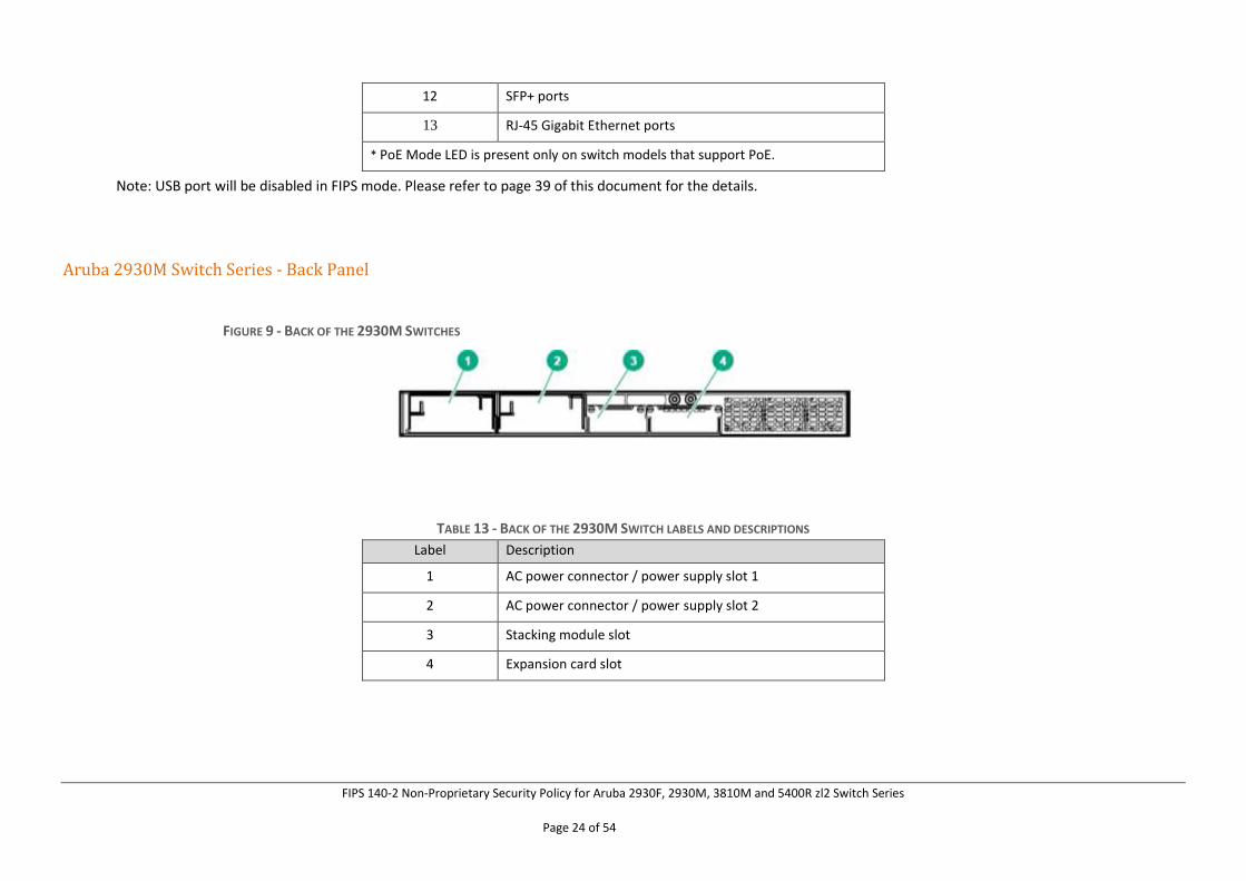
Aruba 2930M Switch Series - Back Panel
FIGURE 9 - BACK OF THE 2930M SWITCHES
TABLE 13 - BACK OF THE 2930M SWITCH LABELS AND DESCRIPTIONS
Label Description
1 AC power connector / power supply slot 1
2 AC power connector / power supply slot 2
3 Stacking module slot
4 Expansion card slot
FIPS 140-2 Non-Proprietary Security Policy for Aruba 2930F, 2930M, 3810M and 5400R zl2 Switch Series
Page 25 of 54
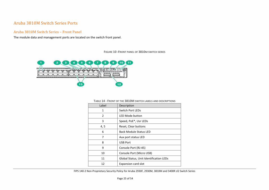
Aruba 3810M Switch Series Ports
Aruba 3810M Switch Series – Front Panel
The module data and management ports are located on the switch front panel.
FIGURE 10 -FRONT PANEL OF 3810M SWITCH SERIES
TABLE 14 - FRONT OF THE 3810M SWITCH LABELS AND DESCRIPTIONS
Label Description
1 Switch Port LEDs
2 LED Mode button
3 Speed, PoE*, Usr LEDs
4, 5 Reset, Clear buttons
6 Back Module Status LED
7 Aux port status LED
8 USB Port
9 Console Port (RJ-45)
10 Console Port (Micro USB)
11 Global Status, Unit Identification LEDs
12 Expansion card slot
FIPS 140-2 Non-Proprietary Security Policy for Aruba 2930F, 2930M, 3810M and 5400R zl2 Switch Series
Page 26 of 54
13 RJ-45 Gigabit Ethernet Ports
* PoE Mode LED is present only on switch models that support PoE.
Note: USB port will be disabled in FIPS mode. Please refer to page 39 of this document for the details.
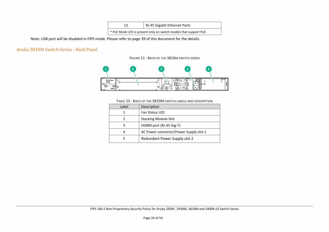
Aruba 3810M Switch Series - Back Panel
FIGURE 11 - BACK OF THE 3810M SWITCH SERIES
TABLE 15 - BACK OF THE 3810M SWITCH LABELS AND DESCRIPTION
Label Description
1 Fan Status LED
2 Stacking Module Slot
3 OOBM port (RJ-45 Gig-T)
4 AC Power connector/Power Supply slot 1
5 Redundant Power Supply slot 2
FIPS 140-2 Non-Proprietary Security Policy for Aruba 2930F, 2930M, 3810M and 5400R zl2 Switch Series
Page 27 of 54
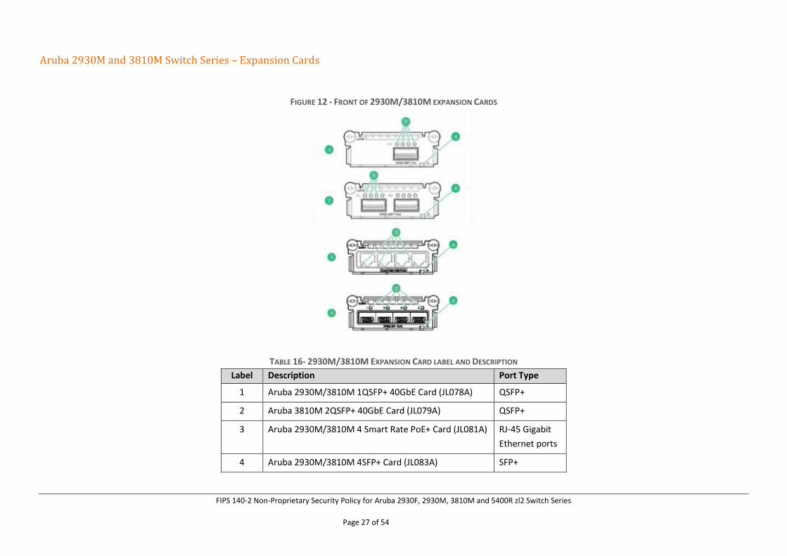
Aruba 2930M and 3810M Switch Series – Expansion Cards
FIGURE 12 - FRONT OF 2930M/3810M EXPANSION CARDS
TABLE 16- 2930M/3810M EXPANSION CARD LABEL AND DESCRIPTION
Label Description Port Type
1 Aruba 2930M/3810M 1QSFP+ 40GbE Card (JL078A) QSFP+
2 Aruba 3810M 2QSFP+ 40GbE Card (JL079A) QSFP+
3 Aruba 2930M/3810M 4 Smart Rate PoE+ Card (JL081A) RJ-45 Gigabit
Ethernet ports
4 Aruba 2930M/3810M 4SFP+ Card (JL083A) SFP+
FIPS 140-2 Non-Proprietary Security Policy for Aruba 2930F, 2930M, 3810M and 5400R zl2 Switch Series
Page 28 of 54
5 Port LEDs
6 Status LEDs
Aruba 5400R zl2 Switch Series Ports
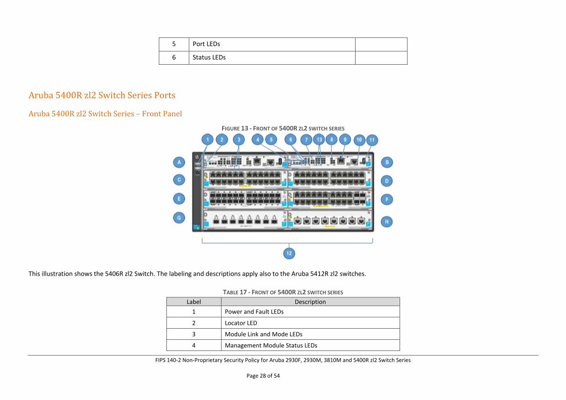
Aruba 5400R zl2 Switch Series – Front Panel
FIGURE 13 - FRONT OF 5400R ZL2 SWITCH SERIES
This illustration shows the 5406R zl2 Switch. The labeling and descriptions apply also to the Aruba 5412R zl2 switches.
TABLE 17 - FRONT OF 5400R ZL2 SWITCH SERIES
Label Description
1 Power and Fault LEDs
2 Locator LED
3 Module Link and Mode LEDs
4 Management Module Status LEDs
FIPS 140-2 Non-Proprietary Security Policy for Aruba 2930F, 2930M, 3810M and 5400R zl2 Switch Series
Page 29 of 54
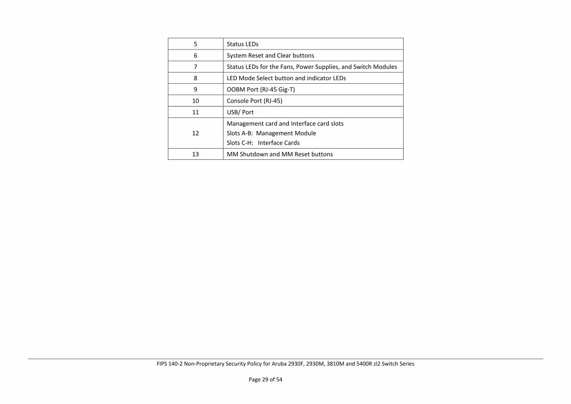
5 Status LEDs
6 System Reset and Clear buttons
7 Status LEDs for the Fans, Power Supplies, and Switch Modules
8 LED Mode Select button and indicator LEDs
9 OOBM Port (RJ-45 Gig-T)
10 Console Port (RJ-45)
11 USB/ Port
12
Management card and Interface card slots
Slots A-B: Management Module
Slots C-H: Interface Cards
13 MM Shutdown and MM Reset buttons
FIPS 140-2 Non-Proprietary Security Policy for Aruba 2930F, 2930M, 3810M and 5400R zl2 Switch Series
Page 30 of 54
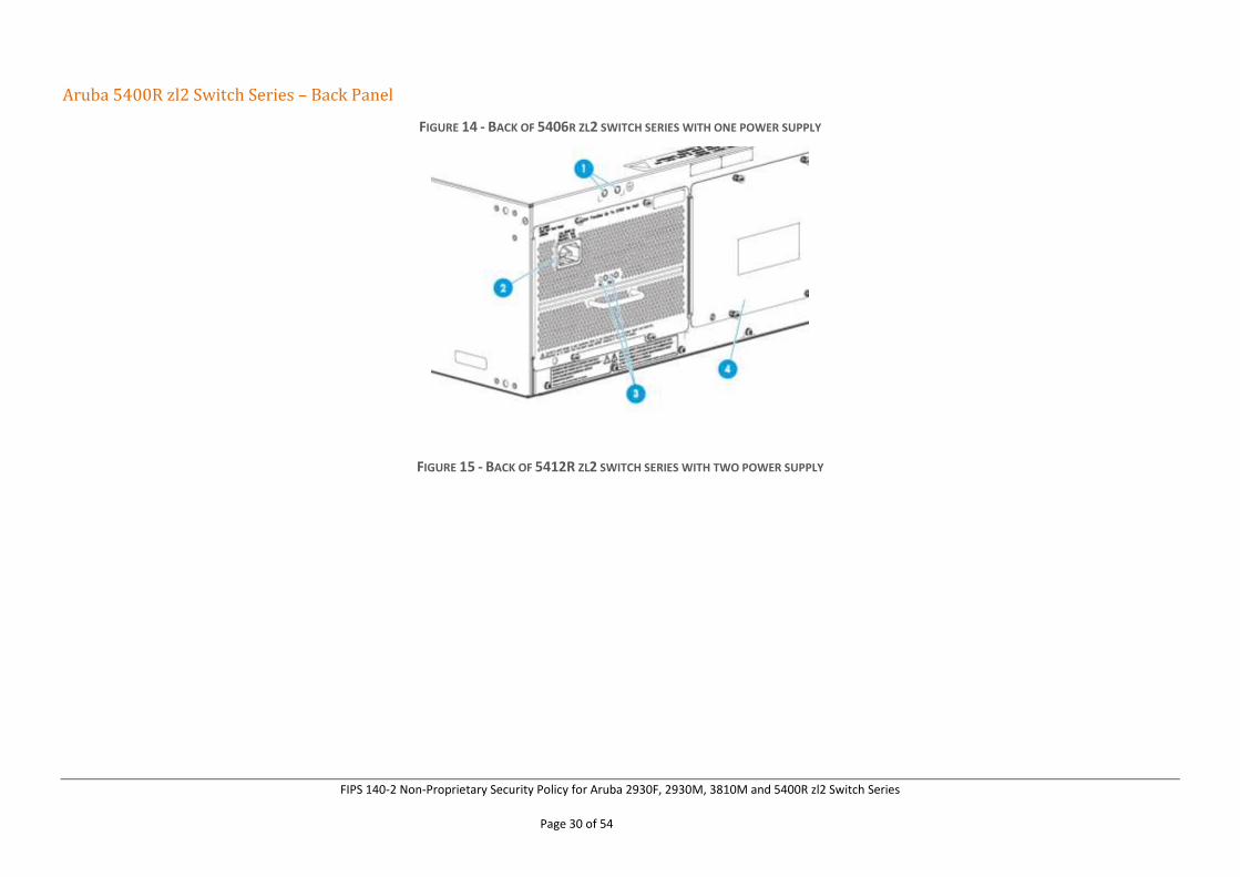
Aruba 5400R zl2 Switch Series – Back Panel
FIGURE 14 - BACK OF 5406R ZL2 SWITCH SERIES WITH ONE POWER SUPPLY
FIGURE 15 - BACK OF 5412R ZL2 SWITCH SERIES WITH TWO POWER SUPPLY
FIPS 140-2 Non-Proprietary Security Policy for Aruba 2930F, 2930M, 3810M and 5400R zl2 Switch Series
Page 31 of 54
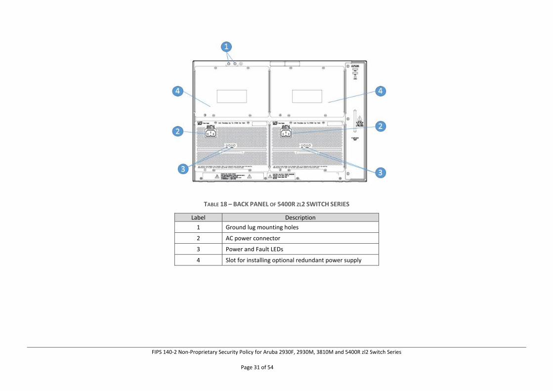
TABLE 18 – BACK PANEL OF 5400R ZL2 SWITCH SERIES
Label Description
1 Ground lug mounting holes
2 AC power connector
3 Power and Fault LEDs
4 Slot for installing optional redundant power supply
FIPS 140-2 Non-Proprietary Security Policy for Aruba 2930F, 2930M, 3810M and 5400R zl2 Switch Series
Page 32 of 54
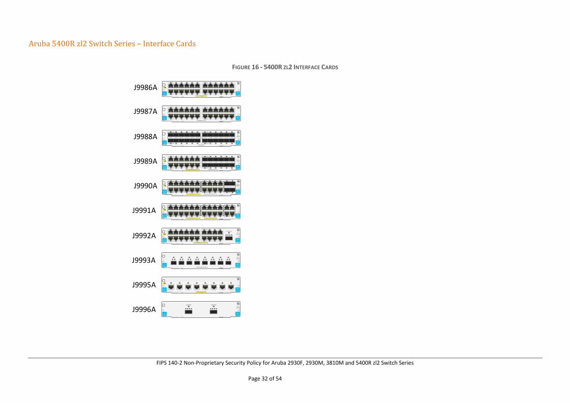
Aruba 5400R zl2 Switch Series – Interface Cards
FIGURE 16 - 5400R ZL2 INTERFACE CARDS
Link
Link
ModeLink
ModeLink
13
14
15
16
17
18
19
20
21
22
23
24
1
2
3
4
5
6
7
8
9
10
11
12
Mode
Mode
PoE+ 10/100/1000Base-T Ports
HP
24p Gig-T
J9986A v3 Module
zl2
Link
Link
ModeLink
ModeLink
13
14
15
16
17
18
19
20
21
22
23
24
1
2
3
4
5
6
7
8
9
10
11
12
Mode
Mode
10/100/1000Base-T Ports
HP
24p Gig-T
J9987A v3 Module
zl2
HP
24p SFP
J9988A
zl2
Use onlysupported
transceivers
v3 Module
13
14
15
16
17
18
19
20
21
22
23
24
ModeLink
ModeLink
1
2
3
4
5
6
7
8
9
10
11
12
ModeLink
ModeLink
1GbE SFP Ports
PoE+ 10/100/1000Base-T Ports (1 - 12)
HP
12p Gig-T
12p SFP
J9989A
zl2
Use onlysupported
transceivers
v3 Module
ModeLink
ModeLink
13
14
15
16
17
18
19
20
21
22
23
24
1
2
3
4
5
6
7
8
9
10
11
12
ModeLink
ModeLink
1GbE SFP Ports (13 - 24)
zl2
ModeLink
ModeLink
1
2
3
4
5
6
7
8
9
10
11
12
ModeLink
ModeLink
13
14
15
16
17
18
19
20
ModeLink
ModeLink
HP
20p Gig-T
4p SFP+
J9990A
21
22
23
24
Use onlysupportedtranceivers
PoE+ 10/100/1000Base-T Ports (1 - 20) 1-GbE / 10 GbE SFP+ Ports (21 - 24)
v3 Module
PoE+ 10/100/1000Base-T Ports (1 - 20)
HP
Smart Rate
20p Gig-T
J9991A
zl2
ModeLink
ModeLink
1
2
3
4
5
6
7
8
9
10
11
12
ModeLink
ModeLink
13
14
15
16
17
18
19
20 v3 Module
ModeLink
ModeLink
21
22
23
24
HP Smart Rate PoE+ Ports (21-24)
PoE+ 10/100/1000Base-T Ports (1 - 20)
HP
20p Gig-T
1p QSFP+
J9992A
zl2
ModeLink
ModeLink
1
2
3
4
5
6
7
8
9
10
11
12
ModeLink
ModeLink
13
14
15
16
17
18
19
20
Use onlysupported
transceivers
v3 Module
21
40-GbE QSFP+
HP
8p SFP+
J9993A
zl2
Use onlysupported
transceivers
v3 Module
1-GbE / 10-GbE SFP+ Ports
1ModeLink
2ModeLink
3ModeLink
4ModeLink
5ModeLink
6ModeLink
7ModeLink
8ModeLink
HP
2p QSFP+
J9996A
zl2
Use onlysupported
transceivers
v3 Module
2
40-GbE QSFP+
1
40-GbE QSFP+
HP
Smart Rate
8 port
J9995A
zl2v3 Module
HP Smart Rate PoE+ Ports
1
ModeLink
2
ModeLink
3
ModeLink
4
ModeLink
5
ModeLink
6
ModeLink
7
ModeLink
8
ModeLink
J9986A
J9987A
J9988A
J9989A
J9990A
J9991A
J9992A
J9993A
J9995A
J9996A
FIPS 140-2 Non-Proprietary Security Policy for Aruba 2930F, 2930M, 3810M and 5400R zl2 Switch Series
Page 33 of 54
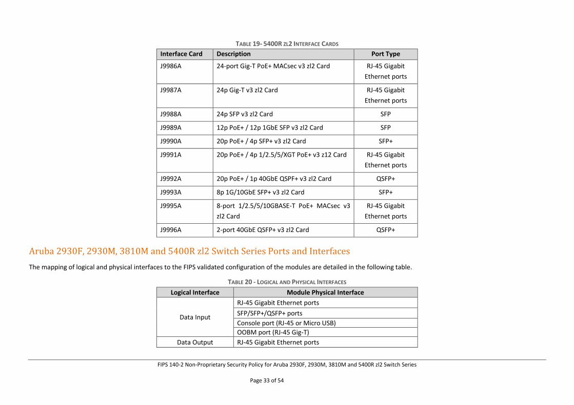
TABLE 19- 5400R ZL2 INTERFACE CARDS
Interface Card Description Port Type
J9986A 24-port Gig-T PoE+ MACsec v3 zl2 Card RJ-45 Gigabit
Ethernet ports
J9987A 24p Gig-T v3 zl2 Card RJ-45 Gigabit
Ethernet ports
J9988A 24p SFP v3 zl2 Card SFP
J9989A 12p PoE+ / 12p 1GbE SFP v3 zl2 Card SFP
J9990A 20p PoE+ / 4p SFP+ v3 zl2 Card SFP+
J9991A 20p PoE+ / 4p 1/2.5/5/XGT PoE+ v3 z12 Card RJ-45 Gigabit
Ethernet ports
J9992A 20p PoE+ / 1p 40GbE QSPF+ v3 zl2 Card QSFP+
J9993A 8p 1G/10GbE SFP+ v3 zl2 Card SFP+
J9995A 8-port 1/2.5/5/10GBASE-T PoE+ MACsec v3
zl2 Card
RJ-45 Gigabit
Ethernet ports
J9996A 2-port 40GbE QSFP+ v3 zl2 Card QSFP+
Aruba 2930F, 2930M, 3810M and 5400R zl2 Switch Series Ports and Interfaces
The mapping of logical and physical interfaces to the FIPS validated configuration of the modules are detailed in the following table.
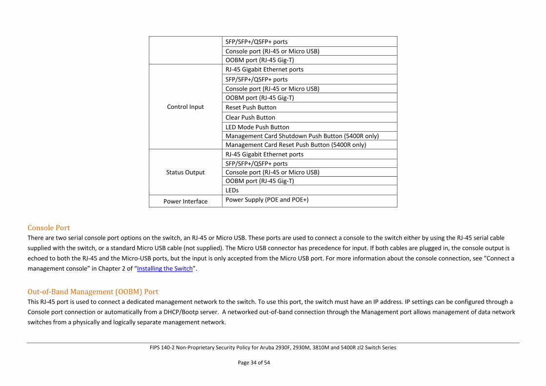
TABLE 20 - LOGICAL AND PHYSICAL INTERFACES
Logical Interface Module Physical Interface
Data Input
RJ-45 Gigabit Ethernet ports
SFP/SFP+/QSFP+ ports
Console port (RJ-45 or Micro USB)
OOBM port (RJ-45 Gig-T)
Data Output RJ-45 Gigabit Ethernet ports
FIPS 140-2 Non-Proprietary Security Policy for Aruba 2930F, 2930M, 3810M and 5400R zl2 Switch Series
Page 34 of 54
SFP/SFP+/QSFP+ ports
Console port (RJ-45 or Micro USB)
OOBM port (RJ-45 Gig-T)
Control Input
RJ-45 Gigabit Ethernet ports
SFP/SFP+/QSFP+ ports
Console port (RJ-45 or Micro USB)
OOBM port (RJ-45 Gig-T)
Reset Push Button
Clear Push Button
LED Mode Push Button
Management Card Shutdown Push Button (5400R only)
Management Card Reset Push Button (5400R only)
Status Output
RJ-45 Gigabit Ethernet ports
SFP/SFP+/QSFP+ ports
Console port (RJ-45 or Micro USB)
OOBM port (RJ-45 Gig-T)
LEDs
Power Interface Power Supply (POE and POE+)
Console Port There are two serial console port options on the switch, an RJ-45 or Micro USB. These ports are used to connect a console to the switch either by using the RJ-45 serial cable
supplied with the switch, or a standard Micro USB cable (not supplied). The Micro USB connector has precedence for input. If both cables are plugged in, the console output is
echoed to both the RJ-45 and the Micro-USB ports, but the input is only accepted from the Micro USB port. For more information about the console connection, see “Connect a
management console” in Chapter 2 of “Installing the Switch”.
Out-of-Band Management (OOBM) Port This RJ-45 port is used to connect a dedicated management network to the switch. To use this port, the switch must have an IP address. IP settings can be configured through a
Console port connection or automatically from a DHCP/Bootp server. A networked out-of-band connection through the Management port allows management of data network
switches from a physically and logically separate management network.
FIPS 140-2 Non-Proprietary Security Policy for Aruba 2930F, 2930M, 3810M and 5400R zl2 Switch Series
Page 35 of 54
To use: connect an RJ-45 network cable to the Management port to manage the module through SSH from a remote PC or a UNIX workstation.
For more information, see the "Network Out-of-Band Management (OOBM)" appendix in the Management and Configuration Guide at:
www.hpe.com/us/en/networking/switches.html.
5 Roles, Services, and Authentication
Roles
Each cryptographic module supports three roles that an operator can assume: a Crypto Officer (Manager) role, a User (Operator) role, and a Security Officer role. Each role is
accessed through proper identity-based authentication to the switch. Services associated with each role are listed in the following sections.
The Crypto Officer is responsible for the set up and initialization of the module as documented in Section 10 (Delivery and Operation) of this document. The Crypto Officer has
complete control of the module and is in charge of configuring all of the settings for each switch. The Crypto Officer can create RSA key pairs for SSHv2 and TLSv1.2. The Crypto
Officer is also in charge of maintaining access control and checking error and intrusion logs.
The User role can show the current secure-mode of the module.
The Security Officer role is to view and delete security logs. This role can also copy security logs from the switch but does not have permission to execute any other commands.
The security logs cannot be viewed or deleted by other roles on the switch.
The devices allow multiple management users to operate the networking device simultaneously. The module does not employ a maintenance interface and does not have a
maintenance role.
Services
The switches can be accessed through:
• Console Port
• SSHv2
• HTTPS/TLS (1.2) WebUI
FIPS 140-2 Non-Proprietary Security Policy for Aruba 2930F, 2930M, 3810M and 5400R zl2 Switch Series
Page 36 of 54
• SNMPv3
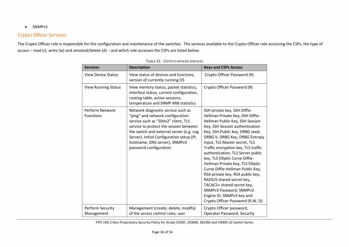
Crypto Officer Services
The Crypto Officer role is responsible for the configuration and maintenance of the switches. The services available to the Crypto Officer role accessing the CSPs, the type of
access – read (r), write (w) and zeroized/delete (d) – and which role accesses the CSPs are listed below:
TABLE 21 - CRYPTO OFFICER SERVICES
Services Description Keys and CSPs Access
View Device Status View status of devices and functions, version of currently running OS
Crypto Officer Password (R)
View Running Status View memory status, packet statistics, interface status, current configuration, routing table, active sessions, temperature and SNMP MIB statistics
Crypto Officer Password (R)
Perform Network Functions
Network diagnostic service such as “ping” and network configuration service such as “SSHv2” client, TLS service to protect the session between the switch and external server (e.g. Log Server), Initial Configuration setup (IP, hostname, DNS server), SNMPv3 password configuration
SSH private key, SSH Diffie-Hellman Private Key, SSH Diffie-Hellman Public Key, SSH Session Key, SSH Session authentication Key, SSH Public key, DRBG seed, DRBG V, DRBG Key, DRBG Entropy Input, TLS Master secret, TLS Traffic encryption key, TLS traffic authentication, TLS Server public key, TLS Elliptic Curve Diffie-Hellman Private Key, TLS Elliptic Curve Diffie-Hellman Public Key, RSA private key, RSA public key, RADIUS shared secret key, TACACS+ shared secret key, SNMPv3 Password, SNMPv3 Engine ID, SNMPv3 key and Crypto Officer Password (R,W, D)
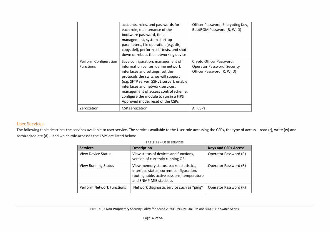
Perform Security Management
Management (create, delete, modify) of the access control rules, user
Crypto Officer password, Operator Password, Security
FIPS 140-2 Non-Proprietary Security Policy for Aruba 2930F, 2930M, 3810M and 5400R zl2 Switch Series
Page 37 of 54
accounts, roles, and passwords for each role, maintenance of the bootware password, time management, system start-up parameters, file operation (e.g. dir, copy, del), perform self-tests, and shut down or reboot the networking device
Officer Password, Encrypting Key, BootROM Password (R, W, D)
Perform Configuration Functions
Save configuration, management of information center, define network interfaces and settings, set the protocols the switches will support (e.g. SFTP server, SSHv2 server), enable interfaces and network services, management of access control scheme, configure the module to run in a FIPS Approved mode, reset of the CSPs
Crypto Officer Password, Operator Password, Security Officer Password (R, W, D)
Zeroization CSP zeroization All CSPs
User Services The following table describes the services available to user service. The services available to the User role accessing the CSPs, the type of access – read (r), write (w) and
zeroized/delete (d) – and which role accesses the CSPs are listed below:
TABLE 22 - USER SERVICES
Services Description Keys and CSPs Access
View Device Status View status of devices and functions, version of currently running OS
Operator Password (R)
View Running Status View memory status, packet statistics, interface status, current configuration, routing table, active sessions, temperature and SNMP MIB statistics
Operator Password (R)
Perform Network Functions Network diagnostic service such as “ping” Operator Password (R)
FIPS 140-2 Non-Proprietary Security Policy for Aruba 2930F, 2930M, 3810M and 5400R zl2 Switch Series
Page 38 of 54
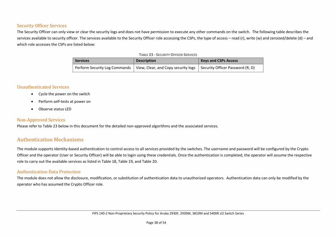
Security Officer Services The Security Officer can only view or clear the security logs and does not have permission to execute any other commands on the switch. The following table describes the
services available to security officer. The services available to the Security Officer role accessing the CSPs, the type of access – read (r), write (w) and zeroized/delete (d) – and
which role accesses the CSPs are listed below:
TABLE 23 - SECURITY OFFICER SERVICES
Services Description Keys and CSPs Access
Perform Security Log Commands View, Clear, and Copy security logs Security Officer Password (R, D)
Unauthenticated Services
• Cycle the power on the switch
• Perform self-tests at power on
• Observe status LED
Non-Approved Services Please refer to Table 23 below in this document for the detailed non-approved algorithms and the associated services.
Authentication Mechanisms
The module supports Identity-based authentication to control access to all services provided by the switches. The username and password will be configured by the Crypto
Officer and the operator (User or Security Officer) will be able to login using these credentials. Once the authentication is completed, the operator will assume the respective
role to carry out the available services as listed in Table 18, Table 19, and Table 20.
Authentication Data Protection
The module does not allow the disclosure, modification, or substitution of authentication data to unauthorized operators. Authentication data can only be modified by the
operator who has assumed the Crypto Officer role.
FIPS 140-2 Non-Proprietary Security Policy for Aruba 2930F, 2930M, 3810M and 5400R zl2 Switch Series
Page 39 of 54
Identity-based Authentication Each operator (Crypto Officer, User, or Security Officer) is authenticated upon initial access to the device. The authentication of the operator is Identity-based. All Switch users
can be either authenticated locally or authenticated via an external RADIUS or TACACS+ server. The authentication method is Username and Password.
To logon to the networking devices, an operator must connect to it through one of the management interfaces (Console port, SSH) and provide the Username and Password.
Each user must be authenticated using username and password. The minimum password length is 8 characters, and the maximum is 64. The passwords can contain the
following, equaling 94 possibilities per character:
lower case letters (26),
upper case letters (26),
special characters (32) and
numeric characters (10)
Therefore, for an 8-character password, the probability of randomly guessing the correct sequence is 1 in 948 (this calculation is based on the use of the typical standard
American QWERTY computer keyboard).
Since the module requires an 8 characters password with 94 possible characters per password character, the probability of randomly guessing the correct sequence is one (1) in
948 = 6.096x10¹⁵, which is less than one in 1,000,000. In addition, in order to successfully guess the sequence in one minute would require the ability to make over 948/60 =
1.016x10¹⁴ guesses per second, which far exceeds the operational capabilities of the module. Therefore, the password strengths meet FIPS 140-2 requirements.
Additionally, each operator (Crypto Officer, User, or Security Officer) can also be authenticated via the RSA based authentication method. When using this authentication
method, as RSA key pair has modulus size of 2048 bits, it provides 112 bits of authentication strength. In such a case, an attacker would have a 1 in 2112 chance of randomly
obtaining the key, which is much stronger than the one in a million chance required by FIPS 140-2. To exceed a one in 100,000 probability of a successful random key guess in
one minute, an attacker would have to be capable of approximately 8.6 x 1031 (5.2 x 1033 /60 = 8.6 x 1031) attempts per second, which far exceeds the operational capabilities of
the module to support.
6 Physical Security Mechanism
The module meets the FIPS 140-2 Level 1 security requirements as production grade equipment.
FIPS 140-2 Non-Proprietary Security Policy for Aruba 2930F, 2930M, 3810M and 5400R zl2 Switch Series
Page 40 of 54
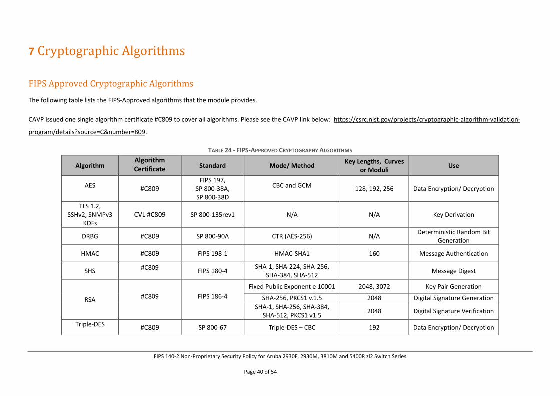
7 Cryptographic Algorithms
FIPS Approved Cryptographic Algorithms
The following table lists the FIPS-Approved algorithms that the module provides.
CAVP issued one single algorithm certificate #C809 to cover all algorithms. Please see the CAVP link below: https://csrc.nist.gov/projects/cryptographic-algorithm-validation-
program/details?source=C&number=809.
TABLE 24 - FIPS-APPROVED CRYPTOGRAPHY ALGORITHMS
Algorithm Algorithm Certificate Standard Mode/ Method
Key Lengths, Curves or Moduli
Use
AES #C809 FIPS 197,
SP 800-38A, SP 800-38D
CBC and GCM 128, 192, 256 Data Encryption/ Decryption
TLS 1.2, SSHv2, SNMPv3
KDFs CVL #C809 SP 800-135rev1 N/A N/A Key Derivation
DRBG #C809 SP 800-90A CTR (AES-256) N/A Deterministic Random Bit
Generation
HMAC #C809 FIPS 198-1 HMAC-SHA1 160 Message Authentication
SHS #C809 FIPS 180-4 SHA-1, SHA-224, SHA-256,
SHA-384, SHA-512 Message Digest
RSA #C809 FIPS 186-4
Fixed Public Exponent e 10001 2048, 3072 Key Pair Generation
SHA-256, PKCS1 v.1.5 2048 Digital Signature Generation
SHA-1, SHA-256, SHA-384, SHA-512, PKCS1 v1.5
2048 Digital Signature Verification
Triple-DES #C809 SP 800-67 Triple-DES – CBC 192 Data Encryption/ Decryption
FIPS 140-2 Non-Proprietary Security Policy for Aruba 2930F, 2930M, 3810M and 5400R zl2 Switch Series
Page 41 of 54
Algorithm Algorithm Certificate Standard Mode/ Method
Key Lengths, Curves or Moduli
Use
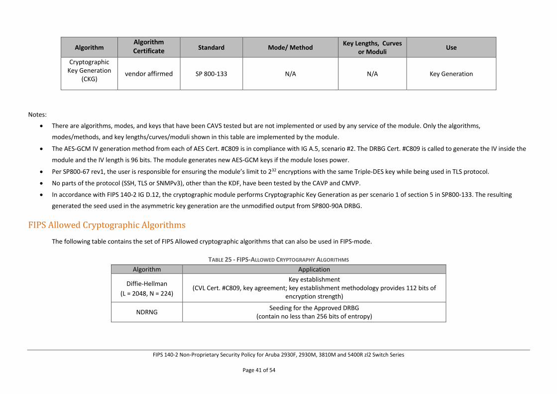
Cryptographic Key Generation
(CKG) vendor affirmed SP 800-133 N/A N/A Key Generation
Notes:
• There are algorithms, modes, and keys that have been CAVS tested but are not implemented or used by any service of the module. Only the algorithms,
modes/methods, and key lengths/curves/moduli shown in this table are implemented by the module.
• The AES-GCM IV generation method from each of AES Cert. #C809 is in compliance with IG A.5, scenario #2. The DRBG Cert. #C809 is called to generate the IV inside the
module and the IV length is 96 bits. The module generates new AES-GCM keys if the module loses power.
• Per SP800-67 rev1, the user is responsible for ensuring the module’s limit to 232 encryptions with the same Triple-DES key while being used in TLS protocol.
• No parts of the protocol (SSH, TLS or SNMPv3), other than the KDF, have been tested by the CAVP and CMVP.
• In accordance with FIPS 140-2 IG D.12, the cryptographic module performs Cryptographic Key Generation as per scenario 1 of section 5 in SP800-133. The resulting
generated the seed used in the asymmetric key generation are the unmodified output from SP800-90A DRBG.
FIPS Allowed Cryptographic Algorithms
The following table contains the set of FIPS Allowed cryptographic algorithms that can also be used in FIPS-mode.
TABLE 25 - FIPS-ALLOWED CRYPTOGRAPHY ALGORITHMS
Algorithm Application
Diffie-Hellman
(L = 2048, N = 224)
Key establishment (CVL Cert. #C809, key agreement; key establishment methodology provides 112 bits of
encryption strength)
NDRNG Seeding for the Approved DRBG
(contain no less than 256 bits of entropy)
FIPS 140-2 Non-Proprietary Security Policy for Aruba 2930F, 2930M, 3810M and 5400R zl2 Switch Series
Page 42 of 54
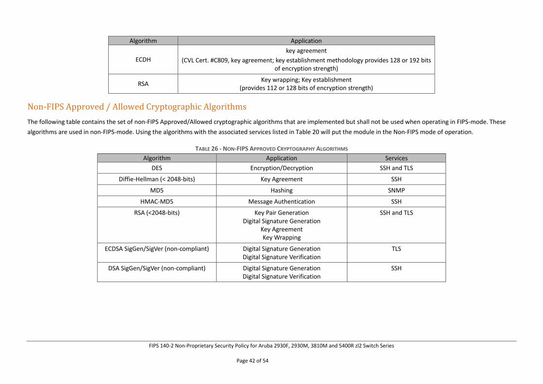
Algorithm Application
ECDH
key agreement
(CVL Cert. #C809, key agreement; key establishment methodology provides 128 or 192 bits of encryption strength)
RSA Key wrapping; Key establishment
(provides 112 or 128 bits of encryption strength)
Non-FIPS Approved / Allowed Cryptographic Algorithms
The following table contains the set of non-FIPS Approved/Allowed cryptographic algorithms that are implemented but shall not be used when operating in FIPS-mode. These
algorithms are used in non-FIPS-mode. Using the algorithms with the associated services listed in Table 20 will put the module in the Non-FIPS mode of operation.
TABLE 26 - NON-FIPS APPROVED CRYPTOGRAPHY ALGORITHMS
Algorithm Application Services
DES Encryption/Decryption SSH and TLS
Diffie-Hellman (< 2048-bits) Key Agreement SSH
MD5 Hashing SNMP
HMAC-MD5 Message Authentication SSH
RSA (<2048-bits) Key Pair Generation Digital Signature Generation
Key Agreement Key Wrapping
SSH and TLS
ECDSA SigGen/SigVer (non-compliant) Digital Signature Generation Digital Signature Verification
TLS
DSA SigGen/SigVer (non-compliant) Digital Signature Generation Digital Signature Verification
SSH
FIPS 140-2 Non-Proprietary Security Policy for Aruba 2930F, 2930M, 3810M and 5400R zl2 Switch Series
Page 43 of 54
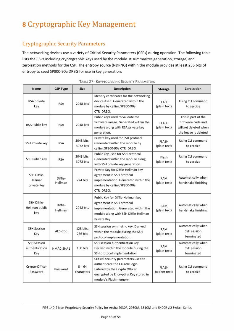
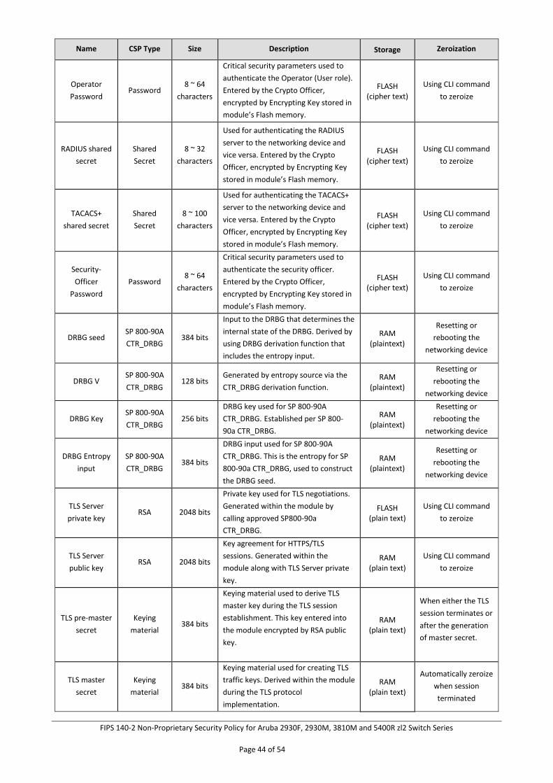
8 Cryptographic Key Management
Cryptographic Security Parameters
The networking devices use a variety of Critical Security Parameters (CSPs) during operation. The following table
lists the CSPs including cryptographic keys used by the module. It summarizes generation, storage, and
zeroization methods for the CSP. The entropy source (NDRNG) within the module provides at least 256 bits of
entropy to seed SP800-90a DRBG for use in key generation.
TABLE 27 - CRYPTOGRAPHIC SECURITY PARAMETERS
Name CSP Type Size Description Storage Zeroization
RSA private
key RSA 2048 bits
Identity certificates for the networking
device itself. Generated within the
module by calling SP800-90a
CTR_DRBG.
FLASH (plain text)
Using CLI command
to zeroize
RSA Public key RSA 2048 bits
Public keys used to validate the
firmware image. Generated within the
module along with RSA private key
generation.
FLASH (plain text)
This is part of the
firmware code and
will get deleted when
the image is deleted
SSH Private key RSA 2048 bits,
3072 bits
Private key used for SSH protocol.
Generated within the module by
calling SP800-90a CTR_DRBG.
FLASH (plain text)
Using CLI command
to zeroize
SSH Public key RSA 2048 bits,
3072 bits
Public key used for SSH protocol. Generated within the module along
with SSH private key generation.
Flash (plain text)
Using CLI command
to zeroize
SSH Diffie-
Hellman
private Key
Diffie-Hellman
224 bits
Private Key for Diffie-Hellman key
agreement in SSH protocol
implementation. Generated within the
module by calling SP800-90a
CTR_DRBG.
RAM (plain text)
Automatically when
handshake finishing
SSH Diffie-
Hellman public
key
Diffie-
Hellman 2048 bits
Public Key for Diffie-Hellman key
agreement in SSH protocol
implementation. Generated within the
module along with SSH Diffie-Hellman
Private Key.
RAM (plain text)
Automatically when
handshake finishing
SSH Session
Key AES-CBC
128 bits,
256 bits
SSH session symmetric key. Derived
within the module during the SSH
protocol implementation.
RAM (plain text)
Automatically when
SSH session
terminated
SSH Session
authentication
Key
HMAC-SHA1 160 bits
SSH session authentication key.
Derived within the module during the
SSH protocol implementation.
RAM (plain text)
Automatically when
SSH session
terminated
Crypto-Officer
Password Password
8 ~ 64
characters
Critical security parameters used to
authenticate the CO role login.
Entered by the Crypto Officer,
encrypted by Encrypting Key stored in
module’s Flash memory.
FLASH (cipher text)
Using CLI command
to zeroize
FIPS 140-2 Non-Proprietary Security Policy for Aruba 2930F, 2930M, 3810M and 5400R zl2 Switch Series
Page 44 of 54
Name CSP Type Size Description Storage Zeroization
Operator
Password Password
8 ~ 64
characters
Critical security parameters used to
authenticate the Operator (User role).
Entered by the Crypto Officer,
encrypted by Encrypting Key stored in
module’s Flash memory.
FLASH (cipher text)
Using CLI command
to zeroize
RADIUS shared
secret
Shared
Secret
8 ~ 32
characters
Used for authenticating the RADIUS
server to the networking device and
vice versa. Entered by the Crypto
Officer, encrypted by Encrypting Key
stored in module’s Flash memory.
FLASH (cipher text)
Using CLI command
to zeroize
TACACS+
shared secret
Shared
Secret
8 ~ 100
characters
Used for authenticating the TACACS+
server to the networking device and
vice versa. Entered by the Crypto
Officer, encrypted by Encrypting Key
stored in module’s Flash memory.
FLASH (cipher text)
Using CLI command
to zeroize
Security-
Officer
Password
Password 8 ~ 64
characters
Critical security parameters used to
authenticate the security officer. Entered by the Crypto Officer,
encrypted by Encrypting Key stored in
module’s Flash memory.
FLASH (cipher text)
Using CLI command
to zeroize
DRBG seed SP 800-90A
CTR_DRBG 384 bits
Input to the DRBG that determines the
internal state of the DRBG. Derived by
using DRBG derivation function that
includes the entropy input.
RAM (plaintext)
Resetting or
rebooting the
networking device
DRBG V SP 800-90A
CTR_DRBG 128 bits
Generated by entropy source via the
CTR_DRBG derivation function. RAM
(plaintext)
Resetting or
rebooting the
networking device
DRBG Key SP 800-90A
CTR_DRBG 256 bits
DRBG key used for SP 800-90A
CTR_DRBG. Established per SP 800-
90a CTR_DRBG.
RAM (plaintext)
Resetting or
rebooting the
networking device
DRBG Entropy
input
SP 800-90A
CTR_DRBG 384 bits
DRBG input used for SP 800-90A
CTR_DRBG. This is the entropy for SP
800-90a CTR_DRBG, used to construct
the DRBG seed.
RAM (plaintext)
Resetting or
rebooting the
networking device
TLS Server
private key RSA 2048 bits
Private key used for TLS negotiations.
Generated within the module by
calling approved SP800-90a
CTR_DRBG.
FLASH (plain text)
Using CLI command
to zeroize
TLS Server
public key RSA 2048 bits
Key agreement for HTTPS/TLS
sessions. Generated within the
module along with TLS Server private
key.
RAM (plain text)
Using CLI command
to zeroize
TLS pre-master
secret
Keying
material 384 bits
Keying material used to derive TLS
master key during the TLS session
establishment. This key entered into
the module encrypted by RSA public
key.
RAM (plain text)
When either the TLS
session terminates or
after the generation
of master secret.
TLS master
secret
Keying
material 384 bits
Keying material used for creating TLS
traffic keys. Derived within the module
during the TLS protocol
implementation.
RAM (plain text)
Automatically zeroize
when session
terminated
FIPS 140-2 Non-Proprietary Security Policy for Aruba 2930F, 2930M, 3810M and 5400R zl2 Switch Series
Page 45 of 54
Name CSP Type Size Description Storage Zeroization
TLS Traffic
encryption key
AES-
CBC/GCM
Triple-DES
128 / 256
bits or
192 bits
Used for encrypting HTTPS/TLS data.
Derived within the module during the
TLS protocol implementation.
RAM (plain text)
Automatically zeroize
when session
terminated
TLS traffic
authentication
key
HMAC-
SHA1/HMAC
-MD5
160
bits/128
bits
Used for authenticating HTTPS/TLS
data. Derived within the module
during the TLS protocol
implementation.
RAM (plain text)
Automatically zeroize
when session
terminated
TLS Elliptic
Curve Diffie-
Hellman
Private Key
EC Diffie-
Hellman
Curves
P-256 and
P-384
Private Key for HTTPS/TLS sessions.
Generated within the module by
calling approved SP800-90a
CTR_DRBG.
RAM (plain text)
Automatically when
handshake finishing
TLS Elliptic
Curve Diffie-
Hellman public
Key
EC Diffie-
Hellman
Curves
P-256 and
P-384
Public Key for HTTPS/TLS sessions.
Generated within the module along
with EC Diffie-Hellman private key.
RAM (plain text)
Automatically when
handshake finishing
Encrypting key AES 256 bits
A key embedded in the firmware, used
to protect CSPs stored in the ‘config’
file.
FLASH (plain text)
This is part of the
firmware code and
will get deleted when
the image is deleted
BOOTROM
Password Password
8 ~ 64
characters
Password used to access the switch in
BootROM mode. Entered by the
Crypto Officer, encrypted by
Encrypting Key stored in module’s
Flash memory.
FLASH (cipher text)
Using CLI command
to zeroize
SNMP v3
Password Password
8 ~ 32
characters
Password used during SNMPv3
authentication. Entered by the Crypto
Officer, encrypted by Encrypting Key
stored in module’s Flash memory.
FLASH (cipher text)
Using CLI command
to zeroize
SNMPv3
engineID
Shared
Secret 96 bits
This is the SNMP engine ID. Entered
by the Crypto Officer, a unique string
used to identify the SNMP engine.
FLASH (plain text)
Using CLI command
to zeroize
SNMP v3 key AES 128 bits
Key used to protect the SNMP traffic.
Derived within the module during the
SNMP v3 protocol implementation.
RAM (plain text)
Using CLI command
to zeroize
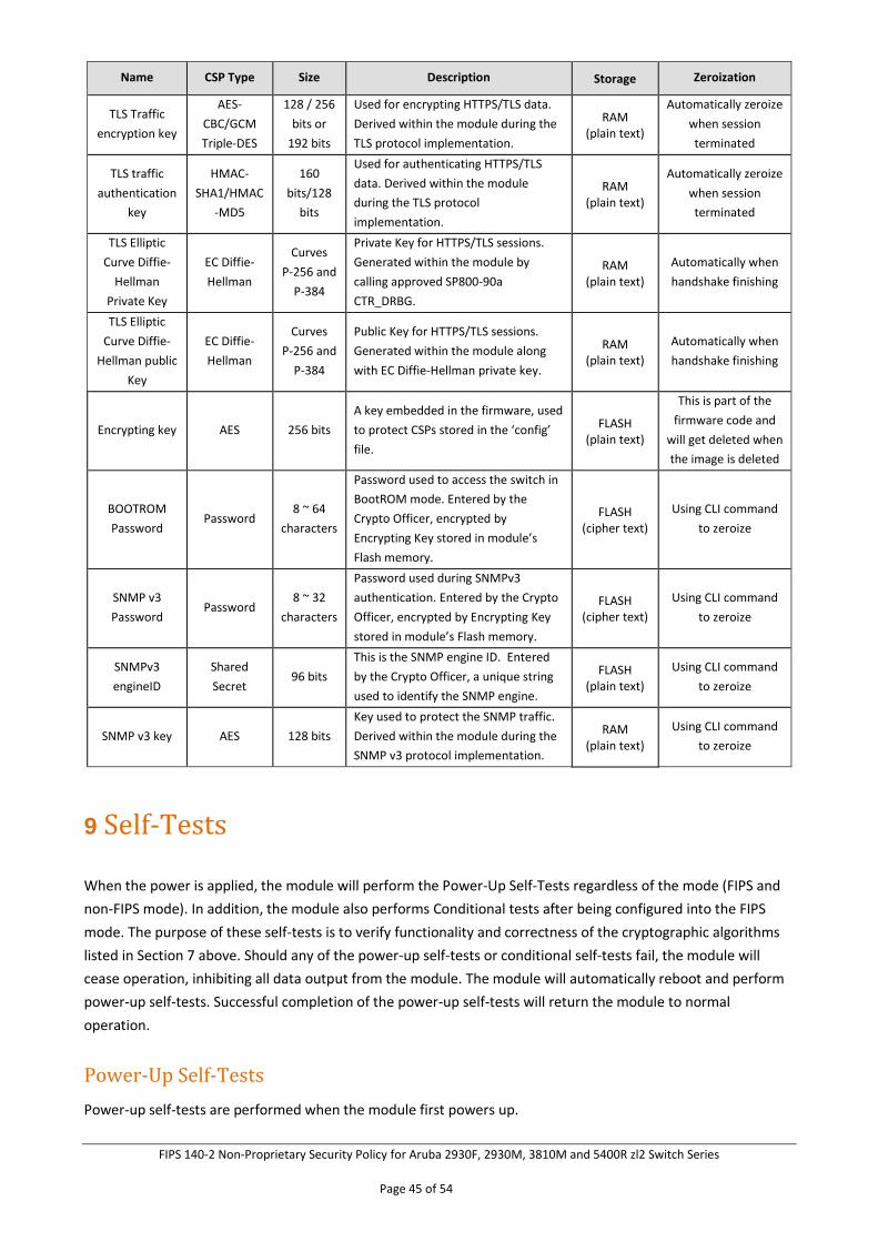
9 Self-Tests
When the power is applied, the module will perform the Power-Up Self-Tests regardless of the mode (FIPS and
non-FIPS mode). In addition, the module also performs Conditional tests after being configured into the FIPS
mode. The purpose of these self-tests is to verify functionality and correctness of the cryptographic algorithms
listed in Section 7 above. Should any of the power-up self-tests or conditional self-tests fail, the module will
cease operation, inhibiting all data output from the module. The module will automatically reboot and perform
power-up self-tests. Successful completion of the power-up self-tests will return the module to normal
operation.
Power-Up Self-Tests
Power-up self-tests are performed when the module first powers up.
FIPS 140-2 Non-Proprietary Security Policy for Aruba 2930F, 2930M, 3810M and 5400R zl2 Switch Series
Page 46 of 54
There are two stages of power-up self-tests that are performed:
• BootROM self-tests
• Firmware self-tests
BootROM Power-Up Self-Tests
The first instance is performed by the BootROM image. The BootROM, used for the selection of a cryptographic
firmware image, performs the following self-tests:
• Known Answer Tests (KATs)
o SHA-1 KAT
o SHA-256 KAT
o SHA-512 KAT
o RSA Sign and Verify KATs (Separate KAT for signing; Separate KAT for verification)
• BootROM integrity check
• Firmware integrity check
The BootROM performs the integrity check on itself to ensure that its image is valid. To perform an integrity
check on itself, as well as on images that can be downloaded within, the BootROM performs an RSA signature
verification (RSA 2048 with SHA-256). If the BootROM integrity check fails, the switch will continuously reboot
and thus must be returned to HPE. If the Firmware integrity check (RSA 2048 with SHA-256) fails, the switch will
transition to the BootROM console where a new image with a valid signature can be downloaded.
Firmware Power-Up Self-Tests
The power-up self-tests are performed on the module either when a FIPS Approved image has been loaded by
the BootROM or when there is a ROM upgrade. These are performed by the corresponding image. The following
power up self-tests are performed:
• AES-CBC Encrypt and Decrypt KATs
• AES-GCM KAT
• CTR DRBG KATs (DRBG Health Tests as specified in SP800-90A Section 11.3 are performed)
• HMAC-SHA1 KAT
• RSA Known Answer Tests (Separate KAT for signing; Separate KAT for verification)
• SHA1/256/512 KATs
• Triple-DES Encrypt and Decrypt KATs
When there is power up self-test failure, the error message indicating which crypto algorithm failed in self-test
will be displayed and the switch will reboot.
An example error message with SHA1 power up self-test failure is:
“Crypto powerup self-tests for SHA1_KAT failed.”
Conditional Self-Tests
Conditional self-tests implemented by the switches:
• CRNGT to DRBG
• CRNGT to NDRNG
• RSA PWCT
• Firmware Load Test
FIPS 140-2 Non-Proprietary Security Policy for Aruba 2930F, 2930M, 3810M and 5400R zl2 Switch Series
Page 47 of 54
10 Delivery and Operation
Secure Delivery
To ensure no one has tampered with the goods during delivery, inspect the Networking switch physical package
and check as follows:
1. Outer Package Inspection
a) Check that the outer carton is in good condition.
b) Check the package for an HPE Quality Seal or IPQC Seal, and ensure that it is intact.
c) Check that the IPQC seal on the plastic bag inside the carton is intact.
d) If any check failed, the goods shall be treated as dead-on-arrival (DOA) goods.
2. Packing List Verification
Check against the packing list for any possible discrepancy in material type and quantity. If any
discrepancy is found, the goods shall be treated as DOA goods.
3. External Visual Inspection
Inspect the cabinet or chassis for any defects, loose connections, damages, and/or illegible marks.
If any surface defect or material shortage is found, the goods shall be treated as DOA goods.
4. Confirm Firmware
a) Version verification
To verify the firmware version, start the networking device, view the self-test result during
startup, and use the show version command to check the firmware version. If firmware
loading failed or the version information is incorrect, please contact HPE for support.
b) RSA with SHA-256 verification
To verify that firmware has not been tampered with, run verify signature flash
<primary/secondary> on the networking device. The command will return a pass or fail
message.
5. DOA (Dead on Arrival)
If the package is damaged, any label/seal is incorrect or tampered with, stop unpacking the
goods, retain the package, and report to HPE for further investigation. The damaged goods
will be replaced if necessary.
Secure Operation
The module is capable of two different modes of operation:
• Standard Secure-Mode - Non-FIPS Approved mode of operation for the switches
• Enhanced Secure-Mode - FIPS-Approved mode of operation for the switches
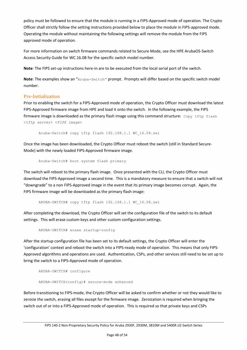
In Enhanced Secure-Mode (FIPS-Approved Mode), services such as Telnet, TFTP, HTTP, and SNMPv2 will be
disabled and other services such as SSHv2, SFTP and SNMPv3 will be enabled.
Auxiliary ports and buttons capable of manual reset and password clearing need to be disabled on the front
panel of the module. Beginning at Pre-Initialization, the initialization steps identified below in this security
FIPS 140-2 Non-Proprietary Security Policy for Aruba 2930F, 2930M, 3810M and 5400R zl2 Switch Series
Page 48 of 54
policy must be followed to ensure that the module is running in a FIPS-Approved mode of operation. The Crypto
Officer shall strictly follow the setting instructions provided below to place the module in FIPS-approved mode.
Operating the module without maintaining the following settings will remove the module from the FIPS
approved mode of operation.
For more information on switch firmware commands related to Secure Mode, see the HPE ArubaOS-Switch
Access Security Guide for WC.16.08 for the specific switch model number.
Note: The FIPS set-up instructions here-in are to be executed from the local serial port of the switch.
Note: The examples show an “Aruba-Switch” prompt. Prompts will differ based on the specific switch model
number.
Pre-Initialization
Prior to enabling the switch for a FIPS-Approved mode of operation, the Crypto Officer must download the latest
FIPS-Approved firmware image from HPE and load it onto the switch. In the following example, the FIPS
firmware image is downloaded as the primary flash image using this command structure: Copy tftp flash
<tftp server> <FIPS image>
Aruba-Switch# copy tftp flash 192.168.1.1 WC_16.08.swi
Once the image has been downloaded, the Crypto Officer must reboot the switch (still in Standard Secure-
Mode) with the newly loaded FIPS-Approved firmware image.
Aruba-Switch# boot system flash primary
The switch will reboot to the primary flash image. Once presented with the CLI, the Crypto Officer must
download the FIPS-Approved image a second time. This is a mandatory measure to ensure that a switch will not
“downgrade” to a non FIPS-Approved image in the event that its primary image becomes corrupt. Again, the
FIPS firmware image will be downloaded as the primary flash image:
ARUBA-SWITCH# copy tftp flash 192.168.1.1 WC_16.08.swi
After completing the download, the Crypto Officer will set the configuration file of the switch to its default
settings. This will erase custom keys and other custom configuration settings.
ARUBA-SWITCH# erase startup-config
After the startup configuration file has been set to its default settings, the Crypto Officer will enter the
‘configuration’ context and reboot the switch into a FIPS-ready mode of operation. This means that only FIPS-
Approved algorithms and operations are used. Authentication, CSPs, and other services still need to be set up to
bring the switch to a FIPS-Approved mode of operation.
ARUBA-SWITCH# configure
ARUBA-SWITCH(config)# secure-mode enhanced
Before transitioning to FIPS-mode, the Crypto Officer will be asked to confirm whether or not they would like to
zeroize the switch, erasing all files except for the firmware image. Zeroization is required when bringing the
switch out of or into a FIPS-Approved mode of operation. This is required so that private keys and CSPs
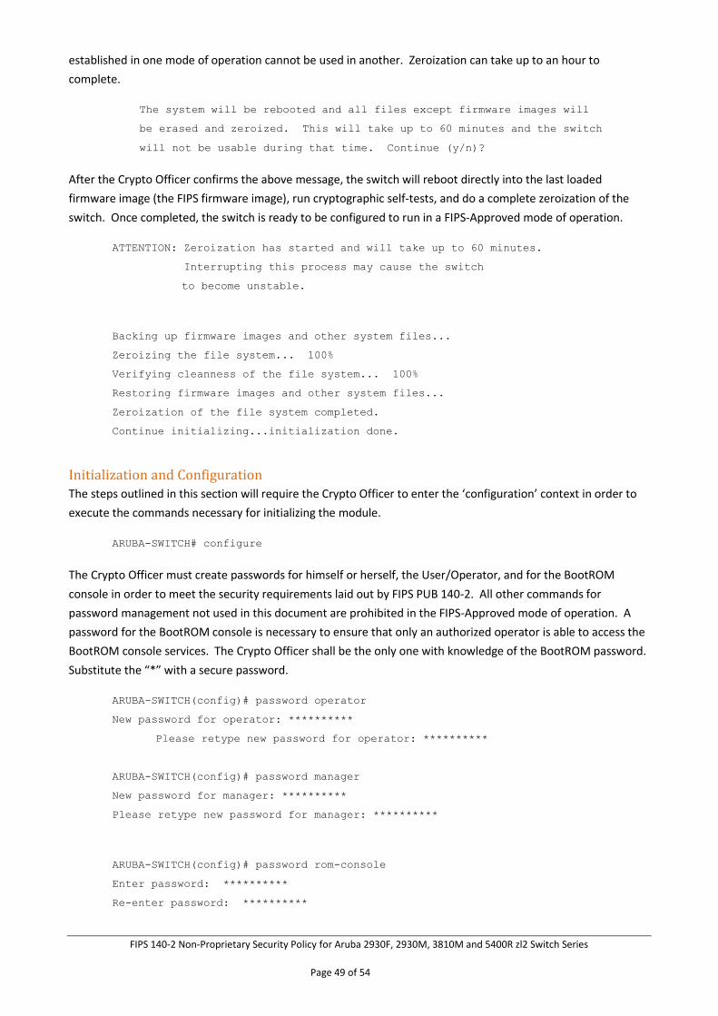
FIPS 140-2 Non-Proprietary Security Policy for Aruba 2930F, 2930M, 3810M and 5400R zl2 Switch Series
Page 49 of 54
established in one mode of operation cannot be used in another. Zeroization can take up to an hour to
complete.
The system will be rebooted and all files except firmware images will
be erased and zeroized. This will take up to 60 minutes and the switch
will not be usable during that time. Continue (y/n)?
After the Crypto Officer confirms the above message, the switch will reboot directly into the last loaded
firmware image (the FIPS firmware image), run cryptographic self-tests, and do a complete zeroization of the
switch. Once completed, the switch is ready to be configured to run in a FIPS-Approved mode of operation.
ATTENTION: Zeroization has started and will take up to 60 minutes.
Interrupting this process may cause the switch
to become unstable.
Backing up firmware images and other system files...
Zeroizing the file system... 100%
Verifying cleanness of the file system... 100%
Restoring firmware images and other system files...
Zeroization of the file system completed.
Continue initializing...initialization done.
Initialization and Configuration The steps outlined in this section will require the Crypto Officer to enter the ‘configuration’ context in order to
execute the commands necessary for initializing the module.
ARUBA-SWITCH# configure
The Crypto Officer must create passwords for himself or herself, the User/Operator, and for the BootROM
console in order to meet the security requirements laid out by FIPS PUB 140-2. All other commands for
password management not used in this document are prohibited in the FIPS-Approved mode of operation. A
password for the BootROM console is necessary to ensure that only an authorized operator is able to access the
BootROM console services. The Crypto Officer shall be the only one with knowledge of the BootROM password.
Substitute the “*” with a secure password.
ARUBA-SWITCH(config)# password operator
New password for operator: **********
Please retype new password for operator: **********
ARUBA-SWITCH(config)# password manager
New password for manager: **********
Please retype new password for manager: **********
ARUBA-SWITCH(config)# password rom-console
Enter password: **********
Re-enter password: **********
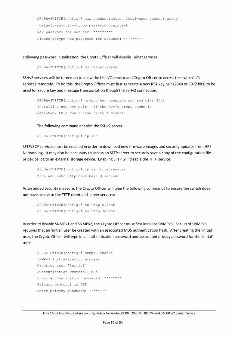
FIPS 140-2 Non-Proprietary Security Policy for Aruba 2930F, 2930M, 3810M and 5400R zl2 Switch Series
Page 50 of 54
ARUBA-SWITCH(config)# aaa authentication local-user secuser group
default-security-group password plaintext
New password for secuser: *********
Please retype new password for secuser: *********
Following password initialization, the Crypto Officer will disable Telnet services.
ARUBA-SWITCH(config)# no telnet-server
SSHv2 services will be turned on to allow the User/Operator and Crypto Officer to access the switch’s CLI
services remotely. To do this, the Crypto Officer must first generate a new RSA key pair (2048 or 3072 bits) to be
used for secure key and message transportation though the SSHv2 connection.
ARUBA-SWITCH(config)# crypto key generate ssh rsa bits 3072
Installing new key pair. If the key/entropy cache is
depleted, this could take up to a minute.
The following command enables the SSHv2 server:
ARUBA-SWITCH(config)# ip ssh
SFTP/SCP services must be enabled in order to download new firmware images and security updates from HPE
Networking. It may also be necessary to access an SFTP server to securely save a copy of the configuration file
or device log to an external storage device. Enabling SFTP will disable the TFTP service.
ARUBA-SWITCH(config)# ip ssh filetransfer
Tftp and auto-tftp have been disabled.
As an added security measure, the Crypto Officer will type the following commands to ensure the switch does
not have access to the TFTP client and server services:
ARUBA-SWITCH(config)# no tftp client
ARUBA-SWITCH(config)# no tftp server
In order to disable SNMPv1 and SNMPv2, the Crypto Officer must first initialize SNMPv3. Set-up of SNMPv3
requires that an ’initial’ user be created with an associated MD5 authentication hash. After creating the ‘initial’
user, the Crypto Officer will type in an authentication password and associated privacy password for the ‘initial’
user:
ARUBA-SWITCH(config)# snmpv3 enable
SNMPv3 Initialization process.
Creating user 'initial'
Authentication Protocol: MD5
Enter authentication password: ********
Privacy protocol is DES
Enter privacy password: ********
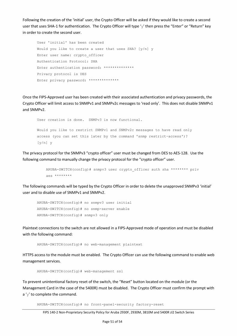
FIPS 140-2 Non-Proprietary Security Policy for Aruba 2930F, 2930M, 3810M and 5400R zl2 Switch Series
Page 51 of 54
Following the creation of the ‘initial’ user, the Crypto Officer will be asked if they would like to create a second
user that uses SHA-1 for authentication. The Crypto Officer will type ‘y’ then press the “Enter” or “Return” key
in order to create the second user.
User 'initial' has been created
Would you like to create a user that uses SHA? [y/n] y
Enter user name: crypto_officer
Authentication Protocol: SHA
Enter authentication password: **************
Privacy protocol is DES
Enter privacy password: **************
Once the FIPS-Approved user has been created with their associated authentication and privacy passwords, the
Crypto Officer will limit access to SNMPv1 and SNMPv2c messages to ‘read only’. This does not disable SNMPv1
and SNMPv2.
User creation is done. SNMPv3 is now functional.
Would you like to restrict SNMPv1 and SNMPv2c messages to have read only
access (you can set this later by the command 'snmp restrict-access')?
[y/n] y
The privacy protocol for the SNMPv3 “crypto officer” user must be changed from DES to AES-128. Use the
following command to manually change the privacy protocol for the “crypto officer” user.
ARUBA-SWITCH(config)# snmpv3 user crypto_officer auth sha ******** priv
aes ********
The following commands will be typed by the Crypto Officer in order to delete the unapproved SNMPv3 ‘initial’
user and to disable use of SNMPv1 and SNMPv2.
ARUBA-SWITCH(config)# no snmpv3 user initial
ARUBA-SWITCH(config)# no snmp-server enable
ARUBA-SWITCH(config)# snmpv3 only
Plaintext connections to the switch are not allowed in a FIPS-Approved mode of operation and must be disabled
with the following command:
ARUBA-SWITCH(config)# no web-management plaintext
HTTPS access to the module must be enabled. The Crypto Officer can use the following command to enable web
management services.
ARUBA-SWITCH(config)# web-management ssl
To prevent unintentional factory reset of the switch, the “Reset” button located on the module (or the
Management Card in the case of the 5400R) must be disabled. The Crypto Officer must confirm the prompt with
a ‘y’ to complete the command.
ARUBA-SWITCH(config)# no front-panel-security factory-reset
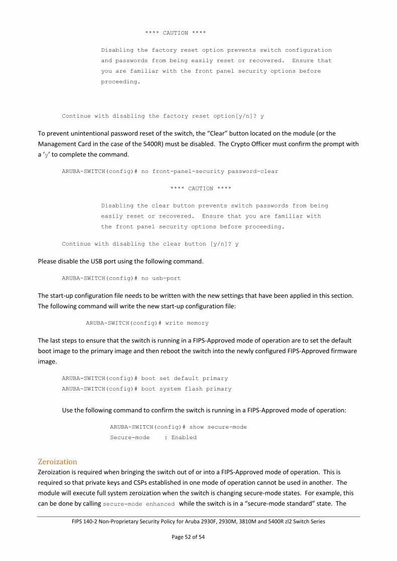
FIPS 140-2 Non-Proprietary Security Policy for Aruba 2930F, 2930M, 3810M and 5400R zl2 Switch Series
Page 52 of 54
**** CAUTION ****
Disabling the factory reset option prevents switch configuration
and passwords from being easily reset or recovered. Ensure that
you are familiar with the front panel security options before
proceeding.
Continue with disabling the factory reset option[y/n]? y
To prevent unintentional password reset of the switch, the “Clear” button located on the module (or the
Management Card in the case of the 5400R) must be disabled. The Crypto Officer must confirm the prompt with
a ‘y’ to complete the command.
ARUBA-SWITCH(config)# no front-panel-security password-clear
**** CAUTION ****
Disabling the clear button prevents switch passwords from being
easily reset or recovered. Ensure that you are familiar with
the front panel security options before proceeding.
Continue with disabling the clear button [y/n]? y
Please disable the USB port using the following command.
ARUBA-SWITCH(config)# no usb-port
The start-up configuration file needs to be written with the new settings that have been applied in this section.
The following command will write the new start-up configuration file:
ARUBA-SWITCH(config)# write memory
The last steps to ensure that the switch is running in a FIPS-Approved mode of operation are to set the default
boot image to the primary image and then reboot the switch into the newly configured FIPS-Approved firmware
image.
ARUBA-SWITCH(config)# boot set default primary
ARUBA-SWITCH(config)# boot system flash primary
Use the following command to confirm the switch is running in a FIPS-Approved mode of operation:
ARUBA-SWITCH(config)# show secure-mode
Secure-mode : Enabled
Zeroization Zeroization is required when bringing the switch out of or into a FIPS-Approved mode of operation. This is
required so that private keys and CSPs established in one mode of operation cannot be used in another. The
module will execute full system zeroization when the switch is changing secure-mode states. For example, this
can be done by calling secure-mode enhanced while the switch is in a “secure-mode standard” state. The
FIPS 140-2 Non-Proprietary Security Policy for Aruba 2930F, 2930M, 3810M and 5400R zl2 Switch Series
Page 53 of 54
module will not execute zeroization if calling secure-mode enhanced while the switch is currently in the
“secure-mode enhanced” state.
Zeroization can also be done by executing the erase all zeroize command. This command has the same
effect as the above command; however the switch will not transition to the opposite mode from which the
command was called in. The secure-mode commands shall only be called when accessing the switch directly
through a serial connection. Otherwise status information about the zeroization process will not be displayed
nor will the operator be able to access the module remotely until remote access has been set up. The only
things that will remain on the switch after zeroization has completed are the BootROM image and the firmware
images.
Secure Management
Once the module has been configured for a FIPS-Approved mode of operation, the Crypto Officer will be
responsible for keeping track of and regenerating RSA key pairs for SSHv2 authentication to the switches.
Remote management is available via SSHv2. The Crypto Officer is the only operator that can change
configuration settings of the switch, which includes access control, password management, and port security.
Physical access to and local control of the module shall be limited to the Crypto Officer.
User Management Access Guidance
The User will be able to access the module remotely via the access methods mentioned in Section 5, Services.
When accessing the switches remotely, the User will be presented with the same CLI interface as if connected
locally. In a remote session, the User is able to see most of the health information and configuration settings of
the switches, but is unable to change them.
BootROM Guidance
The primary purpose of the BootROM console is to download a new firmware image should there be a problem
booting the current FIPS-Approved image. The BootROM may be accessed when rebooting the module locally
through the serial port. When entering into the BootROM, the BootROM selection menu will present the Crypto
Officer with three options. Option 0 allows the Crypto Officer to access BootROM console services. Option 1
and Option 2 allow the Crypto Officer to boot the system into either the primary or secondary firmware image,
respectively. Only a FIPS approved firmware image may be selected from the menu. If nothing is pressed within
3 seconds of being presented with the selection menu, the switch will boot into the last booted image.
When accessing the BootROM console from the BootROM selection menu, the Crypto Officer will be prompted
for the BootROM password which was previously configured by the Crypto Officer during switch initialization.
This password shall be different than the Crypto Officer password. A limited set of commands is available to the
Crypto Officer within the BootROM console that allows the Crypto Officer to download a new image, reboot the
switch, zeroize the switch, or display BootROM image versioning information. The BootROM console may be
exited at any time, to access the image selection menu, via the quit command.
11 Mitigation of Other Attacks
The networking devices do not claim to mitigate any attacks in a FIPS approved mode of operation.
FIPS 140-2 Non-Proprietary Security Policy for Aruba 2930F, 2930M, 3810M and 5400R zl2 Switch Series
Page 54 of 54
12 Documentation References
Aruba Switch Series Documentation References
Access the HPE Networking products page to obtain the up-to-date documents of Aruba-Switches:
http://h17007.www1.hpe.com/us/en/networking/library/#.WqnKvTaWzSd
Search on the products and select from the models listed. Links will be provided with information about the
product, such as datasheet, installation manual, configuration guide, command reference, and other reference
documents.
More information is available on the full line of products for Aruba from the following sources:
• HPE website (www.hpe.com)
• Aruba website (www.arubanetworks.com)
Technical support
For technical or sales related questions please refer to the contacts list on the HPE website:
http://www.hpe.com


![[XLS] · Web viewEXT DISK 1.4GB CMS ENHANCEM 270 MEG INTERNAL CMS ENHANCEM 540 MEG INTERNAL SIGMA DATA, 1.05GB H/D,SCSI, STORAGE DIME 2.1GB,3.5²,5400R STORAGE DIME 2.1GB,3.5²,7200R](https://img.pdfslide.us/doc/110x75/5adab2a17f8b9a6d7e8d0998/xls-viewext-disk-14gb-cms-enhancem-270-meg-internal-cms-enhancem-540-meg-internal.jpg)