Embed Size (px)
Citation preview

Artisan Technology Group is your source for quality new and certified-used/pre-owned equipment
• FAST SHIPPING AND DELIVERY
• TENS OF THOUSANDS OF IN-STOCK ITEMS
• EQUIPMENT DEMOS
• HUNDREDS OF MANUFACTURERS SUPPORTED
• LEASING/MONTHLY RENTALS
• ITAR CERTIFIED SECURE ASSET SOLUTIONS
SERVICE CENTER REPAIRSExperienced engineers and technicians on staff at our full-service, in-house repair center
WE BUY USED EQUIPMENTSell your excess, underutilized, and idle used equipment We also offer credit for buy-backs and trade-inswww.artisantg.com/WeBuyEquipment
REMOTE INSPECTIONRemotely inspect equipment before purchasing with our interactive website at www.instraview.com
LOOKING FOR MORE INFORMATION? Visit us on the web at www.artisantg.com for more information on price quotations, drivers, technical specifications, manuals, and documentation
Contact us: (888) 88-SOURCE | [email protected] | www.artisantg.com
SMViewInstra

Mini-Series Amplifiersfor Brush Type motors
Rockwell Automation/Electro-Craft6950 Washington Avenue SouthEden Prairie, MN 55344
Instruction Manual for Models
DC-35L and DC-45L
T H E R I G H T C O M P A N Y . T H E R I G H T S O L U T I O N .
Artisan Technology Group - Quality Instrumentation ... Guaranteed | (888) 88-SOURCE | www.artisantg.com

P/N 0013-1018-001 Rev E
© 1998 Rockwell International Corporation. All rights reserved.Printed in the United States of America.
Information contained in this manual is subject to change without notice.
Electro-Craft is a trademark of Rockwell Automation. UL and cUL are registered trademarks of Underwriters Laboratories.
Artisan Technology Group - Quality Instrumentation ... Guaranteed | (888) 88-SOURCE | www.artisantg.com

Instruction Manual for Models DC-35L and DC-45L
Contents
IntroContents
Contents Intro-3
List of Figures Intro-5
List of Tables Intro-7
Preface Intro-9
CHAPTER 1 Product InformationElectro-Craft Amplifiers . . . . . . . . . . . . . . . . . . . . . . . . . . . . . . . . . . . . . . . 1-1
Standard Features . . . . . . . . . . . . . . . . . . . . . . . . . . . . . . . . . . . . . . . . . 1-1
Adjustment Controls . . . . . . . . . . . . . . . . . . . . . . . . . . . . . . . . . . . . . . . 1-1
Design Elements . . . . . . . . . . . . . . . . . . . . . . . . . . . . . . . . . . . . . . . . . 1-2
Amplifier Fan . . . . . . . . . . . . . . . . . . . . . . . . . . . . . . . . . . . . . . . . . . . . . 1-4
Model DC-35L . . . . . . . . . . . . . . . . . . . . . . . . . . . . . . . . . . . . . . . . . . . . 1-5
Model DC-45L . . . . . . . . . . . . . . . . . . . . . . . . . . . . . . . . . . . . . . . . . . . . 1-6
CHAPTER 2 InstallationMounting . . . . . . . . . . . . . . . . . . . . . . . . . . . . . . . . . . . . . . . . . . . . . . . 2-1
AC Input . . . . . . . . . . . . . . . . . . . . . . . . . . . . . . . . . . . . . . . . . . . . . . . 2-1
Multiple Axis Power Wiring . . . . . . . . . . . . . . . . . . . . . . . . . . . . . . . . . . . . 2-1
Tachometer Wiring . . . . . . . . . . . . . . . . . . . . . . . . . . . . . . . . . . . . . . . . 2-2
Analog Command Signal (VCS) . . . . . . . . . . . . . . . . . . . . . . . . . . . . . . . . . 2-2
Operational Modes. . . . . . . . . . . . . . . . . . . . . . . . . . . . . . . . . . . . . . . . . . 2-2
Switch Functions . . . . . . . . . . . . . . . . . . . . . . . . . . . . . . . . . . . . . . . . . 2-2
Voltage Mode . . . . . . . . . . . . . . . . . . . . . . . . . . . . . . . . . . . . . . . . . . . 2-2
IR Compensation Mode. . . . . . . . . . . . . . . . . . . . . . . . . . . . . . . . . . . . . . 2-3
Current (Torque) Loop Mode . . . . . . . . . . . . . . . . . . . . . . . . . . . . . . . . . . 2-3
Velocity Mode . . . . . . . . . . . . . . . . . . . . . . . . . . . . . . . . . . . . . . . . . . . 2-3
Startup Procedures. . . . . . . . . . . . . . . . . . . . . . . . . . . . . . . . . . . . . . . . . . 2-4
Current (Torque) Loop Mode . . . . . . . . . . . . . . . . . . . . . . . . . . . . . . . . . . 2-4
Velocity Mode . . . . . . . . . . . . . . . . . . . . . . . . . . . . . . . . . . . . . . . . . . . 2-5
Cautionary Notes . . . . . . . . . . . . . . . . . . . . . . . . . . . . . . . . . . . . . . . . . . 2-6
CHAPTER 3 WarrantyDefective Equipment . . . . . . . . . . . . . . . . . . . . . . . . . . . . . . . . . . . . . . . . 3-1
Return Procedure . . . . . . . . . . . . . . . . . . . . . . . . . . . . . . . . . . . . . . . . . . 3-1
Troubleshooting Help-1
CE Compliance Help-3
Index of Topics Help-5
Documentation Improvement Help-7
Product Support Help-9
Artisan Technology Group - Quality Instrumentation ... Guaranteed | (888) 88-SOURCE | www.artisantg.com

Intro-4 Contents
P/N 0013-1018-001 Rev E
Artisan Technology Group - Quality Instrumentation ... Guaranteed | (888) 88-SOURCE | www.artisantg.com

Instruction Manual for Models DC-35L and DC-45L
List of Figures
IntroList of Figures
CHAPTER 1 Product InformationAmplifier Schematic . . . . . . . . . . . . . . . . . . . . . . . . . . . . . . . . . . . . . . . . . . . (M743) 1-2
Fan Schematic . . . . . . . . . . . . . . . . . . . . . . . . . . . . . . . . . . . . . . . . . . . . . . . (730A) 1-4
DC-35L Amplifier Output Current Derating Curve . . . . . . . . . . . . . . . . . . . . . . (OP1) 1-5
DC-45L Amplifier Output Current Derating Curve . . . . . . . . . . . . . . . . . . . . . . (OP2) 1-6
CHAPTER 2 InstallationTypical Power/Motor Wiring . . . . . . . . . . . . . . . . . . . . . . . . . . . . . . . . . . . (M692E) 2-1
CHAPTER 3 Warranty
Artisan Technology Group - Quality Instrumentation ... Guaranteed | (888) 88-SOURCE | www.artisantg.com

Intro-6 List of Figures
P/N 0013-1018-001 Rev E
Artisan Technology Group - Quality Instrumentation ... Guaranteed | (888) 88-SOURCE | www.artisantg.com

Instruction Manual for Models DC-35L and DC-45L
List of Tables
IntroList of Tables
CHAPTER 1 Product InformationAmplifier Parameters . . . . . . . . . . . . . . . . . . . . . . . . . . . . . . . . . . . . . . . . . . . 1-2
Potentiometer Function . . . . . . . . . . . . . . . . . . . . . . . . . . . . . . . . . . . . . . . . . . 1-2
DIP Switch . . . . . . . . . . . . . . . . . . . . . . . . . . . . . . . . . . . . . . . . . . . . . . . . . . 1-3
Pin Function . . . . . . . . . . . . . . . . . . . . . . . . . . . . . . . . . . . . . . . . . . . . . . . . . 1-3
Fan Parameters . . . . . . . . . . . . . . . . . . . . . . . . . . . . . . . . . . . . . . . . . . . . . . . 1-4
DC-35L Parameters. . . . . . . . . . . . . . . . . . . . . . . . . . . . . . . . . . . . . . . . . . . . . 1-5
DC-35L Accessories . . . . . . . . . . . . . . . . . . . . . . . . . . . . . . . . . . . . . . . . . . . . 1-5
DC-45L Parameters. . . . . . . . . . . . . . . . . . . . . . . . . . . . . . . . . . . . . . . . . . . . . 1-6
DC-45L Accessories / Repair Parts . . . . . . . . . . . . . . . . . . . . . . . . . . . . . . . . . . . 1-6
CHAPTER 2 Installation
CHAPTER 3 Warranty
Artisan Technology Group - Quality Instrumentation ... Guaranteed | (888) 88-SOURCE | www.artisantg.com

Intro-8 List of Tables
P/N 0013-1018-001 Rev E
Artisan Technology Group - Quality Instrumentation ... Guaranteed | (888) 88-SOURCE | www.artisantg.com

Instruction Manual for Models DC-35L and DC-45L
Preface
IntroPreface
Mini-Series amplifiers are used to drive brush type DC motors. They can also interface with digital controllers or can be used as stand-alone amplifiers. A single red/green LED indicates the operating status (red or green). All models are fully protected against overvoltage, overcur-rent, overheating and against short circuits across motor, ground and power leads. The DC-35L and DC-45L amplifiers operate directly from 120 VAC power.
Potentiometer (pot) controls allow you to adjust Loop Gain, Current Limit, VCS Gain and IR Compensation (Test/Offset). The Test/Offset pot can also be used as an on-board input signal for test purposes.
Typical Applications◆ Medical Equipment
◆ Packaging Machinery
◆ Material Handling
◆ Textile Machinery
◆ Robotics
Artisan Technology Group - Quality Instrumentation ... Guaranteed | (888) 88-SOURCE | www.artisantg.com

Intro-10 Preface
P/N 0013-1018-001 Rev E
Artisan Technology Group - Quality Instrumentation ... Guaranteed | (888) 88-SOURCE | www.artisantg.com

Instruction Manual for Models DC-35L and DC-45L
CHAPTER 1: Product Information
Electro-Craft Amplifiers
Standard Features
◆ Small size, low cost, ease of use
◆ Surface-mount board technology
◆ DIP switches that configure different modes of operation
◆ Four quadrant regenerative operation
◆ Short Circuit protection
◆ AC Power Cord for off-line operation
Adjustment Controls
◆ I Limit adjusts both continuous and peak hand picked current limits by maintaining their ratio (50%).
◆ Offset/Test adjusts the zero velocity offset on board signal generator.
◆ VCS Gain adjusts ratio between input signal and output variables (voltage, current, and velocity).
◆ Loop Gain adjusts the system response.
Intro
!
WARNING Mini-Series Amplifiers are not capable of sourcing optical encoder power.
TIPOutput current must be derated when the heat sink and cooling fan are not used.
Artisan Technology Group - Quality Instrumentation ... Guaranteed | (888) 88-SOURCE | www.artisantg.com

1-2 Product Information
P/N 0013-1018-001 Rev E
Design Elements
TABLE 1.1 Amplifier Parameters
Item Value
Part number See Table 1.7 or Table 1.9
Temperature (ambient)operating storage
32° to 122° F (0° to 50° C)-40° to 176° F (-40° to 80° C)
Relative humidity 5% to 95% non-condensing
Current foldback 50% automatic
Switching frequency 22 kHz
Load inductance 200 mH minimum
Input signal range ±10V (±15 VDC maximum)
Current output monitor (MCO)
Amps to Volts
Intro
FIGURE 1.1 Amplifier Schematic (M743)
TABLE 1.2 Potentiometer Function
Potentiometer Function Turning CW
Loop Gain Loop gain, adjustment in voltage and veloc-ity modes. Voltage-to-current scaling factor adjustment in current mode.
Increases Loop Gain
Current Limit Current limit. Adjusts both continuous and peak current limit by maintaining their ratio(I cont = 1/2 I peak).
Increases Current Limit
VCS Gain VCS gain. Adjusts the ratio between input signal and output variables (voltage, current and velocity).
Increases VCS Input Gain
Test/Offset Test/offset. Used to adjust any imbalance in the input signal or in the amplifier. When SW4 (DIP switch) is ON, the sensitivity of this pot is greatly increased, so it can be used as an on-board signal source for test purposes.
Not applicable
Artisan Technology Group - Quality Instrumentation ... Guaranteed | (888) 88-SOURCE | www.artisantg.com
Product Information 1-3
Instruction Manual for Models DC-35L and DC-45L
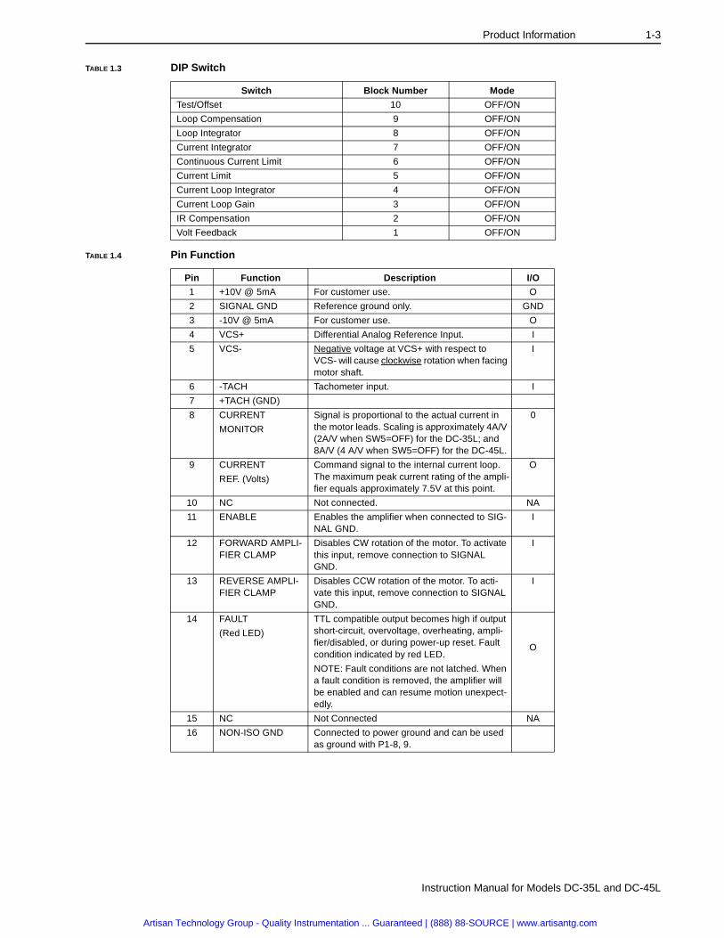
TABLE 1.3 DIP Switch
Switch Block Number Mode
Test/Offset 10 OFF/ON
Loop Compensation 9 OFF/ON
Loop Integrator 8 OFF/ON
Current Integrator 7 OFF/ON
Continuous Current Limit 6 OFF/ON
Current Limit 5 OFF/ON
Current Loop Integrator 4 OFF/ON
Current Loop Gain 3 OFF/ON
IR Compensation 2 OFF/ON
Volt Feedback 1 OFF/ON
TABLE 1.4 Pin Function
Pin Function Description I/O
1 +10V @ 5mA For customer use. O
2 SIGNAL GND Reference ground only. GND
3 -10V @ 5mA For customer use. O
4 VCS+ Differential Analog Reference Input. I
5 VCS- Negative voltage at VCS+ with respect to VCS- will cause clockwise rotation when facing motor shaft.
I
6 -TACH Tachometer input. I
7 +TACH (GND)
8 CURRENT
MONITOR
Signal is proportional to the actual current in the motor leads. Scaling is approximately 4A/V (2A/V when SW5=OFF) for the DC-35L; and 8A/V (4 A/V when SW5=OFF) for the DC-45L.
0
9 CURRENT
REF. (Volts)
Command signal to the internal current loop. The maximum peak current rating of the ampli-fier equals approximately 7.5V at this point.
O
10 NC Not connected. NA
11 ENABLE Enables the amplifier when connected to SIG-NAL GND.
I
12 FORWARD AMPLI-FIER CLAMP
Disables CW rotation of the motor. To activate this input, remove connection to SIGNAL GND.
I
13 REVERSE AMPLI-FIER CLAMP
Disables CCW rotation of the motor. To acti-vate this input, remove connection to SIGNAL GND.
I
14 FAULT
(Red LED)
TTL compatible output becomes high if output short-circuit, overvoltage, overheating, ampli-fier/disabled, or during power-up reset. Fault condition indicated by red LED.
NOTE: Fault conditions are not latched. When a fault condition is removed, the amplifier will be enabled and can resume motion unexpect-edly.
O
15 NC Not Connected NA
16 NON-ISO GND Connected to power ground and can be used as ground with P1-8, 9.
Artisan Technology Group - Quality Instrumentation ... Guaranteed | (888) 88-SOURCE | www.artisantg.com

1-4 Product Information
P/N 0013-1018-001 Rev E
Amplifier Fan
TABLE 1.5 Fan Parameters
Item Value
Part number 9090-0237
Air flow 35.9 CFM @ 120 VAC, 60 Hz
Speed 3150 RPM
Operating temperature -10°C to +70°C
Power input 10.5 Watts
Voltage 115V, 50/60 Hz
Housing metal
Impeller metal
Rotation clockwise, looking at rotor
Intro
FIGURE 1.2 Fan Schematic (730A)
Artisan Technology Group - Quality Instrumentation ... Guaranteed | (888) 88-SOURCE | www.artisantg.com

Product Information 1-5
Instruction Manual for Models DC-35L and DC-45L
Model DC-35L
TABLE 1.6 DC-35L Parameters
Item Value
Part number See Table 1.7
Weight 4 lbs, 2.5 oz. (1.9 Kg)
Powerinput auxiliary
25-130 VAC±10 VDC (2) 5 mAmps max
Output current, 1Øcontinuouspeak
±8A±16A
Intro
FIGURE 1.3 DC-35L Amplifier Output Current Deratin g Curve (OP1)
TABLE 1.7 DC-35L Accessories
Part Number Description StallTorque(lb-in)
MaxSpeed(RPM)
PowerSupply(VAC)
9077-0647Amplifier, with heat sink
Not applicable
9077-0646Amplifier, without heat sink
9106-0063 Connector kit, included with amplifier
0721-34-001 Motor,recommended for DC-35L
10 2750 120
0721-32-010 Motor,recommended for DC-35L
17 2750 120
0721-31-041 Motor,recommended for DC-35L
23 2750 120
0642-31-001 Motor,recommended for DC-35L
6 4800 120
0643-33-004 Motor,recommended for DC-35L
8 4800 120
0644-36-012 Motor,recommended for DC-35L
12 1850 120
Artisan Technology Group - Quality Instrumentation ... Guaranteed | (888) 88-SOURCE | www.artisantg.com

1-6 Product Information
P/N 0013-1018-001 Rev E
Model DC-45L
TABLE 1.8 DC-45L Parameters
Item Value
Part number See Table 1.9
Weight 4 lbs, 5.0 oz. (2.0 Kg)
Powerinput shunt
25-130 VACup to 30 W continuous (fused)
Output current, 1Øcontinuouspeak
±15A±30A
Intro
FIGURE 1.4 DC-45L Amplifier Output Current Deratin g Curve (OP2)
TABLE 1.9 DC-45L Accessories / Repair Parts
Part Number Description StallTorque(lb-in)
MaxSpeed(RPM)
PowerSupply(VAC)
9077-0649Amplifier, with heat sink
Not applicable
9077-0648Amplifier, without heat sink
9106-0063 Connector kit, included with amplifier
0721-34-001 Motor,recommended for DC-45L
10 2750 120
0721-32-010 Motor,recommended for DC-45L
17 2750 120
0721-31-041 Motor,recommended for DC-45L
23 2750 120
0727-32-010 Motor,recommended for DC-45L
28 2750 120
0728-39-003 Motor,recommended for DC-45L
35 2750 120
0642-31-011 Motor,recommended for DC-45L
6 4800 120
Artisan Technology Group - Quality Instrumentation ... Guaranteed | (888) 88-SOURCE | www.artisantg.com

Product Information 1-7
Instruction Manual for Models DC-35L and DC-45L
0643-33-004 Motor,recommended for DC-45L
8 4800 120
0644-36-012 Motor,recommended for DC-45L
12 1850 120
Bussman P/N MDL3
Shunt Fuse, 3 A motor delay
Not applicable
TABLE 1.9 DC-45L Accessories / Repair Parts (continued)
Part Number Description StallTorque(lb-in)
MaxSpeed(RPM)
PowerSupply(VAC)
Artisan Technology Group - Quality Instrumentation ... Guaranteed | (888) 88-SOURCE | www.artisantg.com

1-8 Product Information
P/N 0013-1018-001 Rev E
Artisan Technology Group - Quality Instrumentation ... Guaranteed | (888) 88-SOURCE | www.artisantg.com

Instruction Manual for Models DC-35L and DC-45L
CHAPTER 2: Installation
MountingThe amplifier must be mounted in the vertical position away from other heat producing devices. In multiple axis applications, a minimum of 1.0" separation between each chassis is recommended.
AC InputThe amplifier may be powered with a 25-130 VAC source, or directly off the 120 VAC power line. To avoid shock hazard, connect the power cord to a power receptacle with earth ground.
Multiple Axis Power WiringThe AC or line power can be common to more than one amplifier. Power leads from each amplifier should terminate at the power supply source.
!
WARNINGA shock hazard potentially exists from improper or unguarded electrical equipment. Install a #16 or #18 green ground wire from the amplifier and motor cases to earth ground. Cable shield termination should also be grounded as shown in Figure 2.1.
Intro
FIGURE 2.1 Typical Power/Motor Wirin g (M692E)
Artisan Technology Group - Quality Instrumentation ... Guaranteed | (888) 88-SOURCE | www.artisantg.com
2-2 Installation
P/N 0013-1018-001 Rev E
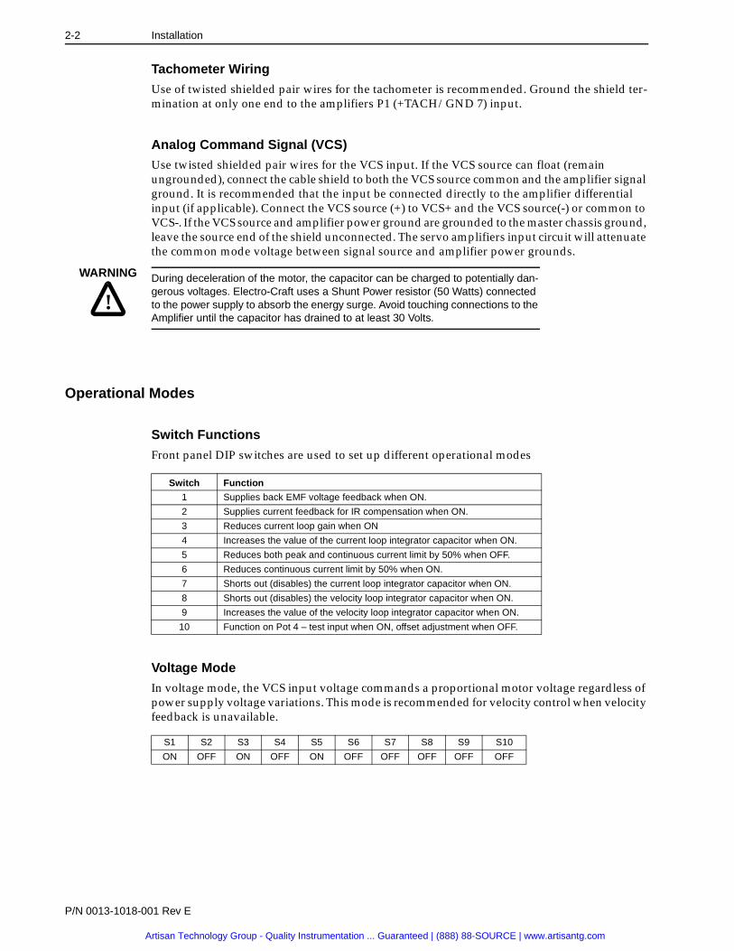
Tachometer Wiring
Use of twisted shielded pair wires for the tachometer is recommended. Ground the shield ter-mination at only one end to the amplifiers P1 (+TACH/GND 7) input.
Analog Command Signal (VCS)
Use twisted shielded pair wires for the VCS input. If the VCS source can float (remain ungrounded), connect the cable shield to both the VCS source common and the amplifier signal ground. It is recommended that the input be connected directly to the amplifier differential input (if applicable). Connect the VCS source (+) to VCS+ and the VCS source(-) or common to VCS-. If the VCS source and amplifier power ground are grounded to the master chassis ground, leave the source end of the shield unconnected. The servo amplifiers input circuit will attenuate the common mode voltage between signal source and amplifier power grounds.
Warnin g: Ener gy Surges
Operational Modes
Switch Functions
Front panel DIP switches are used to set up different operational modes
Voltage Mode
In voltage mode, the VCS input voltage commands a proportional motor voltage regardless of power supply voltage variations. This mode is recommended for velocity control when velocity feedback is unavailable.
Intro
!
WARNING During deceleration of the motor, the capacitor can be charged to potentially dan-gerous voltages. Electro-Craft uses a Shunt Power resistor (50 Watts) connected to the power supply to absorb the energy surge. Avoid touching connections to the Amplifier until the capacitor has drained to at least 30 Volts.
Switch Function
1 Supplies back EMF voltage feedback when ON.
2 Supplies current feedback for IR compensation when ON.
3 Reduces current loop gain when ON
4 Increases the value of the current loop integrator capacitor when ON.
5 Reduces both peak and continuous current limit by 50% when OFF.
6 Reduces continuous current limit by 50% when ON.
7 Shorts out (disables) the current loop integrator capacitor when ON.
8 Shorts out (disables) the velocity loop integrator capacitor when ON.
9 Increases the value of the velocity loop integrator capacitor when ON.
10 Function on Pot 4 – test input when ON, offset adjustment when OFF.
S1 S2 S3 S4 S5 S6 S7 S8 S9 S10
ON OFF ON OFF ON OFF OFF OFF OFF OFF
Artisan Technology Group - Quality Instrumentation ... Guaranteed | (888) 88-SOURCE | www.artisantg.com

Installation 2-3
Instruction Manual for Models DC-35L and DC-45L
IR Compensation Mode
If there is a load torque variation when running in voltage mode, the motor current will vary, since torque is proportional to motor current. Since the motor windings have resistance, the actual motor voltage is reduced by the product of motor current and resistance. Therefore, motor speed which is proportional to motor voltage (terminal voltage minus IR drop) varies with the load torque.
To compensate for the internal motor voltage drop, a voltage proportional to motor current can be added to the IR compensation level. If the feed back voltage is high enough to cause a rise in motor voltage with increased motor current, instability occurs. This is due to the fact increased voltage increases motor speed and load current which in turn, increases motor voltage. If a great deal of motor torque change is anticipated, it may be necessary to add a tachometer to the motor.
To adjust IR feedback, start with a very high (or open) IR feedback resistor (R8) with an unloaded motor shaft. Command a low motor speed (about 20-200 RPM). Note that the motor shaft can be stalled easily without any IR feedback. Decreasing the IR feedback resistor increases motor torque at lower speeds. Too much IR feedback, for examples, too low of a resistor value, will cause motor run-away when torque is applied to the motor shaft.
Current (Torque) Loop Mode
Current mode produces a torque output from the motor proportional to the VCS voltage input. Motor output torque is proportional to the motor current. Current mode is particularly impor-tant if the servo amplifier is used with a digital position controller. Under this condition, a movement of the motor shaft from the desired position causes a large correcting torque, or “stiffness”. Therefore, this mode may produce a “run away” condition if operated without a controller.
Velocity Mode
The addition of a tachometer to the motor shaft produces a voltage proportional to speed. The tachometer output voltage replaces the motor terminal voltage as the controlled variable. Since this voltage is proportional to the motor speed, the operating mode is velocity mode.
Note that the speed is dependent on terminal voltage and motor current. The motor current is, in turn, dependent on the load torque which includes both constant friction torque and the torque to accelerate or decelerate the load. Velocity mode is more complex than voltage mode, but also results in the best performance among all the operating modes.
Performance in the velocity mode is dependent on the load inertia and characteristics, and should be verified with the motor connected to the actual load.
S1 S2 S3 S4 S5 S6 S7 S8 S9 S10
ON ON ON OFF ON OFF OFF OFF OFF OFF
S1 S2 S3 S4 S5 S6 S7 S8 S9 S10
OFF OFF ON OFF ON OFF OFF ON OFF OFF
S1 S2 S3 S4 S5 S6 S7 S8 S9 S10
OFF OFF ON OFF ON OFF OFF OFF OFF OFF
Artisan Technology Group - Quality Instrumentation ... Guaranteed | (888) 88-SOURCE | www.artisantg.com

2-4 Installation
P/N 0013-1018-001 Rev E
Startup Procedures
Current (Torque) Loop Mode
Motor Leads
1. Connect the motor leads to P2. Pin 1 is MOTOR+ and Pin 2 is MOTOR-. To reduce the effect of radiated electrical noise, the motor leads and the supply leads should be run as twisted pairs or as shielded cable. Keep the motor and power leads away from the sig-nal leads. Do not connect any tachometer leads.
Interface Connections
2. Install the required interface connections to P1 as outlined in Table 1.4.
Initial Potentiometer Setting
3. Rotate loop gain potentiometer full CW (15 turns maximum). Rotate all other potenti-ometers to full CCW position.
Apply Power
4. Apply power; verify that the LED indicator is red. Once the amplifier is enabled and no fault conditions are present, the LED will turn green.
Current Limit
5. Set the current limit potentiometer to a suitable current level for the motor being used.
The current limit potentiometer adjusts both peak and continuous current at the same time. The amplifier will output peak current for 2 seconds before gradually reducing the current limit to 50% of the peak current setting.
Test/Offset
6. Adjust the test/offset potentiometer until the motor shaft remains stationary.
VCS Gain
7. Adjust the VCS gain potentiometer for the desired scaling of VCS Volts to motor torque. After adjusting, bring the VCS input to zero and readjust the test/offset potentiometer if necessary.
Turns CW Percent of Rated Current
5 33%
10 66%
15 100%
Artisan Technology Group - Quality Instrumentation ... Guaranteed | (888) 88-SOURCE | www.artisantg.com

Installation 2-5
Instruction Manual for Models DC-35L and DC-45L
Velocity Mode
Motor Leads
1. Connect the motor leads to P2. Pin 1 is MOTOR+ and Pin 2 is MOTOR-. To reduce the effect of radiated electrical noise, the motor leads and the supply leads should be run as twisted pairs or as shielded cable. Keep the motor and power leads away from the sig-nal leads.
Tachometer Leads
2. Connect the tachometer leads to P1. Pin 7 is +TACH and Pin 6 is -TACH.
Interface Connections
3. Install the required interface connections to P1 as outlined in Table 1.4.
Initial Potentiometer Setting
4. Rotate all potentiometers at least 15 turns CCW (to full CCW position).
Apply Power
5. Apply power; verify that the LED indicator is red. Once the amplifier is enabled and no fault conditions are present, the LED will turn green.
Current Limit
6. Slowly turn the current limit potentiometer CW until the motor starts to rotate. If it accelerates toward full speed, remove power and reverse the tachometer leads. Apply power again and the motor should rotate slowly.
Test/Offset Control
7. Adjust the test/offset potentiometer until the motor shaft remains stationary.
Current Limit Control
8. Set the current limit potentiometer to a suitable current level for the motor being used.
The current limit potentiometer adjusts both peak and continuous current at the same time. The amplifier will output peak current for 2 seconds before gradually reducing the current limit to 50% of the peak current setting.
Loop Gain Control
9. Turn the loop gain potentiometer CW until the motor shaft starts to oscillate, then turn back sufficiently to stop the oscillation.
VCS Gain
10. After the desired system response is obtained by appropriate adjustment of the loop gain potentiometer, adjust the VCS gain potentiometer for the desired scaling of VCS Volts to motor RPM. After adjusting, bring the VCS input to zero and readjust the test/offset potentiometer if necessary.
Turns CW Percent of Rated Current
5 33%
10 66%
15 100%
Artisan Technology Group - Quality Instrumentation ... Guaranteed | (888) 88-SOURCE | www.artisantg.com

2-6 Installation
P/N 0013-1018-001 Rev E
Cautionary NotesDo Not Reverse the Power Supply Leads
Use Sufficient Power Supply Capacitance
Do Not Spin The Motor Without Power
Do Not Short The Motor
Protect Against Electrical Noise
!Damage can result from reversing current flow through the amplifier. Always check the polarity of wire leads before connecting.
Intro
!Insufficient power supply capacitance problems occur particularly with high induc-tance motors. During braking much of the stored mechanical energy is fed back into the power supply which charges the output capacitor to a higher voltage. If the charge reaches the amplifier's overvoltage shutdown point, output current and brak-ing will cease. At that time the energy stored due to the motor inductance continues to flow through diodes in the amplifier to further charge the power supply capacitor. The actual voltage rise depends upon the power supply capacitance, motor speed, and inductance. For example, a 2mH motor at 20 amperes can charge a 2000µF capacitor up to 30V.
Intro
!The motor acts as a generator and will charge the power supply capacitors through the amplifier. Too high a speed may cause overvoltage breakdown in the power MOSFETs. An amplifier with an internal power converter operating from a high voltage supply will become operative.
Intro
!When the motor is shorted, its own generated voltage may produce a current flow as high as 10 times the amplifier peak current. The short itself should not damage the amplifier but may damage the motor. If the connection arcs or opens while the motor is spinning rapidly, this high current flows back into the amplifier (due to stored energy from the motor inductance) and may damage the amplifier.
Intro
!The main source of amplifier noise is the high DV/DT (typically about 1V/nanosec-ond) of the amplifier's output power MOSFETs. Unfiltered motor outputs can introduce noise in digital encoder signal wires if they are routed in the same cable harness without shielding.
Artisan Technology Group - Quality Instrumentation ... Guaranteed | (888) 88-SOURCE | www.artisantg.com

Instruction Manual for Models DC-35L and DC-45L
CHAPTER 3: Warrant y
The following product warranty and returned goods information summarizes the product war-ranty and return policy of Electro-Craft. A copy of the formal “Returned Goods and Field Service Policy” is available upon request.
Defective EquipmentIf you are unable to correct a problem, and the product is defective, you may return the unit to your Electro-Craft distributor for repair or replacement.
There are no field serviceable parts in the drive. If the drive fails, the unit should be returned to the factory for repair or replacement. To save unnecessary work and repair charges, please verify that the drive unit is defective before returning it for repair.
Limitations to warranty coverage are detailed in “Returned Goods and Field Service Policy.” Products that have been modified by the customer, physically mishandled, or otherwise abused through incorrect wiring, inappropriate settings, and so on, are exempt from the warranty plan.
Return ProcedureTo ensure accurate processing and prompt return of any Rockwell Automation / Electro-Craft product, the following procedure must be followed:
1. Call your distributor to obtain a Return Material Authorization (RMA) number. Do not return the drive or any other equipment without a valid RMA number. Returns lacking a valid RMA number will not be accepted and will be returned to the sender.
2. Pack the drive in the original shipping carton. Rockwell Automation is not responsible or liable for damage resulting from improper packaging or shipment of returned prod-ucts.
3. Include a detailed description of the problem and any relevant information.
Repaired units are shipped via UPS Ground delivery. If another method of shipping is desired, please indicate this when requesting the RMA number and include this information with the returned unit.
Artisan Technology Group - Quality Instrumentation ... Guaranteed | (888) 88-SOURCE | www.artisantg.com

3-2 Warranty
P/N 0013-1018-001 Rev E
Artisan Technology Group - Quality Instrumentation ... Guaranteed | (888) 88-SOURCE | www.artisantg.com

Instruction Manual for Models DC-35L and DC-45L
Troubleshooting
HelpTroubleshooting
Things to CheckOverload Fault
1. Verify that the motor shaft rotates freely with no power applied and while uncoupled from the load.
2. Verify that the minimum inductance requirement is met.
Heat Sink Temperature
1. Verify that the heat sink temperature is less than 65°C.
Overvoltage Shutdown
1. Check the input power voltage. If the voltage is greater than the value listed in the specifications, check the AC power line connected to the power supply for the proper value.
2. Check the regenerative energy absorbed during deceleration. Use a voltmeter or oscil-loscope to monitor the power supply voltage. If the supply voltage increases above the specified values, additional power supply capacitance is necessary. Additional capaci-tors must be electrolytic type and located within one foot of the amplifier.
Undervoltage Shutdown
1. Verify that the power supply voltage is above the minimum listed in the specifications.
Short Circuit Fault
1. Check each motor lead for shorts with respect to motor housing and power ground.
2. Measure motor resistance between motor leads with the amplifier disconnected.
Status
1. Check ALL INHIBIT inputs for the proper levels.
Causes of Erratic Operation
1. Improper grounding.
2. Noisy command signal. Check for system ground loops.
3. Mechanical backlash, dead-band, slippage, etc.
4. Excessive tachometer noise.
Artisan Technology Group - Quality Instrumentation ... Guaranteed | (888) 88-SOURCE | www.artisantg.com

Help-2 Troubleshooting
P/N 0013-1018-001 Rev E
Artisan Technology Group - Quality Instrumentation ... Guaranteed | (888) 88-SOURCE | www.artisantg.com

Instruction Manual for Models DC-35L and DC-45L
CE Compliance
HelpCE Compliance
Although amplifiers are not considered “machinery” under directive 89/336/EEC, machine builders prefer to use components that can meet electromagnetic compatibility (EMC) standards when properly installed.
EMC Wiring RequirementsThe DC-35L and DC-45L conform to the generic and basic standards of EN50081-1:1992 and EN50082-2:1995 when installed in accordance with the installation instructions below.
ConsiderationsGeneral
1. Shielded cables must be used for all interconnect cables to the amplifier and the shield of the cable must be grounded at the closest ground point with the least amount of resis-tance.
2. The amplifiers metal enclosure must be grounded to the closest ground point with the least amount of resistance.
3. The amplifier must be mounted in such a manner that the connectors and exposed printed circuit board are not accessible to be touched by personnel when the product is in operation. If this is unavoidable there must be clear instructions that the amplifier is not to be touched during operation. This is to avoid possible malfunction due to electro-static discharge from personnel.
Analog Input Amplifiers
4. A Fair Rite model 043167251 round suppression core must be fitted to the low level sig-nal interconnect cables to prevent pickup from external RF fields.
PWM Input Amplifiers
5. A Fair Rite model 043167251 round suppression core must be fitted to the PWM input cable to electromagnetic emissions.
MOSFET Switching Amplifiers
6. A Fair Rite model 043167251 round suppression core must be fitted at the load cable connector to electromagnetic emissions.
7. An appropriately rated Schaffner 2080 series AC power filter in combination with a Fair Rite model 5977002701 torroid (placed on the supply end of the filter) must be fitted to the AC supply to any MOSFET amplifier system in order to reduce conducted emis-sions fed back into the supply network.
Fitting of AC Power Filters
8. The above mentioned AC power filters should be mounted flat against the enclosure of the product using the two mounting lugs provided on the filter. Paint should be removed from the enclosure where the filter is fitted to ensure good metal to metal con-tact. The filter should be mounted as close to the point where the AC power enters the enclosure as possible. Also the AC power cable on the load end of the filter should be routed as far from the AC power cable on the supply end of the filter and all other cables and circuitry to minimize RF coupling.
Artisan Technology Group - Quality Instrumentation ... Guaranteed | (888) 88-SOURCE | www.artisantg.com

Help-4 CE Compliance
P/N 0013-1018-001 Rev E
Artisan Technology Group - Quality Instrumentation ... Guaranteed | (888) 88-SOURCE | www.artisantg.com

Instruction Manual for Models DC-35L and DC-45L
Index of Topics
HelpIndex of Topics
AAC Input 2-1Adjustments 1-1Amplifier
controls 1-1current foldback 1-2fan 1-4features 1-1humidity 1-2load inductance 1-2part number 1-2signal range 1-2switching frequency 1-2temperature
operating 1-2storate 1-2
Analog Command Signal, see VCSApplications Intro-9
CCautions 2-6CE Compliance
AC filters Help-3analog Help-3DC-35L Help-3DC-45L Help-3general Help-3MOSFET Help-3PWM Help-3
Controls 1-1Current
foldback 1-2monitor 1-2
Current Loop mode 2-3
DDC motors Intro-9DC-35L
AC input 2-1accessories 1-5EMC standards Help-3mounting 2-1overcurrent Intro-9overheating Intro-9overvoltage Intro-9short circuits Intro-9specifications 1-5
DC-45LAC input 2-1accessories 1-6EMC standards Help-3mounting 2-1overcurrent Intro-9overheating Intro-9overvoltage Intro-9short circuits Intro-9shunt power 1-6specifications 1-6
Digital controllers Intro-9
DIP Switchcurrent integrator 1-3current limit 1-3feedback 1-3IR compensation 1-3loop compensation 1-3loop gain 1-3loop integrator 1-3offset 1-3test 1-3
EElectrical 1-2Electromagnetic compatibility, see EMCEMC
requirements Help-3wiring Help-3
FFan 1-4Fault
overload Help-1short circuit Help-1
Features 1-1
IIR Compensation Mode 2-3
LLED Intro-9
MMode
current loop 2-3IR compensation 2-3torque 2-3velocity 2-3voltage 2-2
ModelDC-35L 1-5DC-45L 1-6
Mounting 2-1
OOvercurrent Intro-9Overheating
heat sink Help-1protection Intro-9
Overvoltageprotection Intro-9shutdown Help-1
Artisan Technology Group - Quality Instrumentation ... Guaranteed | (888) 88-SOURCE | www.artisantg.com

Help-6 Index of Topics
P/N 0013-1018-001 Rev E
PPin
AMPLIFIER CLAMP 1-3CURRENT MONITOR 1-3CURRENT REF 1-3ENABLE 1-3FAULT 1-3NON-ISO GND 1-3red LED 1-3SIGNAL GND 1-3TACH 1-3VCS 1-3
Potentiometercurrent limit 1-2loop gain 1-2offset 1-2test 1-2VCS gain 1-2
PowerAC input 2-1shunt 1-6wiring 2-1
Product support Help-9
RReturn procedure 3-1
SShort circuit
fault Help-1protection Intro-9
Specificationscurrent foldback 1-2humidity 1-2load inductance 1-2signal range 1-2switching frequency 1-2temperature 1-2
Support network Help-9
TTachometer 2-2Technical assistance Help-9Temperature
operating 1-2storage 1-2
Torque Mode 2-3Troubleshooting
erratic operation Help-1heat sink Help-1overload Help-1overvoltage Help-1short circuit Help-1status Help-1undervoltage Help-1
VVelocity mode 2-3Voltage mode 2-2
WWarning
dangerous voltage 2-2optical encoder power 1-1shock hazard 2-1
Warranty coverage 3-1Wiring
power 2-1tachometer 2-2
Artisan Technology Group - Quality Instrumentation ... Guaranteed | (888) 88-SOURCE | www.artisantg.com

Instruction Manual for Models DC-35L and DC-45L
Documentation Improvement
HelpDocumentation Improvement
Rockwell Automation/Electro-Craft
Technical Communications Department6950 Washington Avenue SouthEden Prairie, MN 55344Fax: 612-942-3636
DOCUMENTATION IMPROVEMENT FORM
Manual Number: _________________________
Page Number: ___________________________
Comments: Please give page numbers and specific paragraphs that the change will affect. Include markups from the document or attach additional pages if necessary.
____________________________________________________________________________________________________________________
____________________________________________________________________________________________________________________
____________________________________________________________________________________________________________________
____________________________________________________________________________________________________________________
____________________________________________________________________________________________________________________
____________________________________________________________________________________________________________________
____________________________________________________________________________________________________________________
____________________________________________________________________________________________________________________
____________________________________________________________________________________________________________________
____________________________________________________________________________________________________________________
____________________________________________________________________________________________________________________
____________________________________________________________________________________________________________________
____________________________________________________________________________________________________________________
What improvements will this suggestion provide? ____________________________________________________________________________
____________________________________________________________________________________________________________________
____________________________________________________________________________________________________________________
____________________________________________________________________________________________________________________
____________________________________________________________________________________________________________________
Originator:_____________________________________ City: ___________________ State: _______ Zip: ____________________________
Company: _____________________________________ Phone: _______________________________________________________________
Address: ______________________________________ Date: ________________________________________________________________
Thank you for your comments.
Technical Writing Internal Use:
Follow-Up Action
Artisan Technology Group - Quality Instrumentation ... Guaranteed | (888) 88-SOURCE | www.artisantg.com

Artisan Technology Group - Quality Instrumentation ... Guaranteed | (888) 88-SOURCE | www.artisantg.com

Instruction Manual for Models DC-35L and DC-45L
Product Support
HelpProduct Support
Electro-Craft product support is available over the phone. When you call, you should be at your computer and have the hardware and software manuals at hand. Be prepared to give the fol-lowing information:
◆ The version numbers of the hardware and software products
◆ The type of hardware that you are using
◆ The fault indicators and the exact wording of any messages that appears on your screen
◆ How you have tried to solve the problem
Distributor & Representative NetworkElectro-Craft has a wide network of distributors that are trained to support our products. If you encounter problems, call the distributor or representative where you purchased the product before contacting the factory.
Applications Engineers and Field ServiceIn the United States you can reach the Electro-Craft factory based support staff by phone between 7:30 AM and 5:00 PM (CST) Monday through Friday at 1-800-328-3983. The applications engi-neers can assist you with programming difficulties as well as ideas for how to approach your automation task. Should your problem require on-site assistance, field service is available.
The applications engineers can also be reached via fax at 1-612-942-3636. The fax machine is open 24 hours 7 days a week. Faxes will be answered during regular business hours only.
In Europe, support can be obtained through Electro-Craft Limited. The support staff may be reached by telephone between 8:30 and 17:30 local time, Monday through Friday at [44] 1270-580142, or via fax at [44] 1270-580141.
Bulletin Board Service (BBS)If you have a modem, you can reach the Electro-Craft BBS 24 hours a day, seven days a week at 1-612-942-3618. The following services are available through the BBS:
◆ Example application programs
◆ Technical bulletins, product update and errata information
◆ Leave messages and files for the application engineers
◆ Help with your application
Artisan Technology Group - Quality Instrumentation ... Guaranteed | (888) 88-SOURCE | www.artisantg.com

Mini-Series Amplifiersfor Brush Type motots
Rockwell Automation/Electro-Craft6950 Washington Avenue SouthEden Prairie, MN 55344612.942.3600 – main612.942.3636 – fax800.328.3983 – technical support
P/N 0013-1018-001 Rev E
Instruction Manual for Models
DC-35L and DC-45L
Artisan Technology Group - Quality Instrumentation ... Guaranteed | (888) 88-SOURCE | www.artisantg.com

Artisan Technology Group is your source for quality new and certified-used/pre-owned equipment
• FAST SHIPPING AND DELIVERY
• TENS OF THOUSANDS OF IN-STOCK ITEMS
• EQUIPMENT DEMOS
• HUNDREDS OF MANUFACTURERS SUPPORTED
• LEASING/MONTHLY RENTALS
• ITAR CERTIFIED SECURE ASSET SOLUTIONS
SERVICE CENTER REPAIRSExperienced engineers and technicians on staff at our full-service, in-house repair center
WE BUY USED EQUIPMENTSell your excess, underutilized, and idle used equipment We also offer credit for buy-backs and trade-inswww.artisantg.com/WeBuyEquipment
REMOTE INSPECTIONRemotely inspect equipment before purchasing with our interactive website at www.instraview.com
LOOKING FOR MORE INFORMATION? Visit us on the web at www.artisantg.com for more information on price quotations, drivers, technical specifications, manuals, and documentation
Contact us: (888) 88-SOURCE | [email protected] | www.artisantg.com
SMViewInstra