Embed Size (px)
Citation preview

ArtiosCAD Enterprise
Administrator Guide
ArtiosCAD Enterprise
ii
Contents
1. Location and Copyright............................................................................................................................................................ 8
2. Welcome........................................................................................................................................................................................ 10
Introduction................................................................................................................................................................................10
Before you begin............................................................................................................................................................10
Package contents.......................................................................................................................................................... 10
Important folders, libraries, and files of Esko ArtiosCAD.............................................................................. 11
Display adapter optimization in Windows Server™ 2003...................................................................................... 13
Operating system notes.......................................................................................................................................................13
Support for VMware® Fusion............................................................................................................................................14
3. Installing and Configuring ArtiosCAD Enterprise........................................................................................................15
Installing ArtiosCAD Enterprise......................................................................................................................................... 15
Step 1 - Installing Esko WebCenter.......................................................................................................................15
Step 2 - Running the Board Importer Batch File..............................................................................................22
Step 3 - Loading the Esko ArtiosCAD Defaults................................................................................................ 22
Step 4 - Creating a New Company and Location............................................................................................23
Step 5 - Creating a New Group.............................................................................................................................. 23
Step 6 - Creating New Users...................................................................................................................................24
Step 7 - Setting a New User’s Group Membership.........................................................................................26
Step 8 - Inviting New Users to the Shared Defaults Project........................................................................26
Step 9 - Installing ArtiosCAD Enterprise on a User’s Computer.................................................................27
Post-Installation Configuration Tasks.....................................................................................................................28
Configuring ArtiosCAD Enterprise....................................................................................................................................33
Using the Flute Browser............................................................................................................................................. 34
Using the Board Browser...........................................................................................................................................37
Defaults...............................................................................................................................................................................50
Always Showing All Boards.......................................................................................................................................61
Defaults Availability overview....................................................................................................................................62
Configuring the Automatic Naming Templates.................................................................................................. 66
Using Spot Colors in PDF files................................................................................................................................67
4. Installing Esko ArtiosCAD..................................................................................................................................................... 70
Introduction................................................................................................................................................................................70
Performing a Typical installation.......................................................................................................................................71
Typical Standalone or Server installation............................................................................................................. 73
Typical Standard Client Installation........................................................................................................................ 74
Performing an Advanced installation.............................................................................................................................. 74
Using other databases with Esko ArtiosCAD..............................................................................................................77
Other database notes.................................................................................................................................................. 77

Contents
iii
Advanced Upgrading of Esko ArtiosCAD on a server.............................................................................................78
Notes and warnings before you begin..................................................................................................................78
Upgrading other databases with Esko ArtiosCAD.................................................................................................... 78
Other database notes.................................................................................................................................................. 78
Changing to SQL Server 2005 Express Edition on the database server..........................................................79
Exporting database information from the old database.................................................................................79
Loading the upgrade.................................................................................................................................................... 80
Automatic migration......................................................................................................................................................81
Manual migration............................................................................................................................................................82
ArtiosCAD Database Migration utility command-line options......................................................................88
Changing to SQL Server 2005 Express Edition on client systems.....................................................................89
5. Peripherals....................................................................................................................................................................................90
Installing a Windows printer...............................................................................................................................................90
Output Destinations............................................................................................................................................................... 91
Starting the ArtiosIO program...................................................................................................................................92
Creating an Output Destination............................................................................................................................... 93
Installing CAM Devices.........................................................................................................................................................94
Getting started................................................................................................................................................................ 94
Preliminaries..................................................................................................................................................................... 94
Example 1 - Setting up a Kongsberg XL44 samplemaker............................................................................95
Example 2 - Setting up an Alphamerics RS-232 samplemaker..................................................................97
Example 3 - Adding a Calcomp DrawingBoard III digitizer.......................................................................... 98
Advanced digitizer setup..........................................................................................................................................102
6. Other tasks................................................................................................................................................................................ 111
Uninstalling Esko ArtiosCAD............................................................................................................................................111
Removing individual Esko ArtiosCAD Programs............................................................................................ 111
Uninstalling SolidWorks separately from Esko ArtiosCAD..........................................................................111
Removing MSDE..........................................................................................................................................................111
Removing the Esko ArtiosCAD ODBC entry....................................................................................................112
Uninstalling a patch....................................................................................................................................................112
Modifying and Repairing Esko ArtiosCAD................................................................................................................. 112
Loading an Esko ArtiosCAD patch............................................................................................................................... 112
Working with the ArtiosIO Status program................................................................................................................ 113
Using Floating Licenses.....................................................................................................................................................113
Configuring floating licenses...................................................................................................................................114
Troubleshooting............................................................................................................................................................ 116
Upgrading Esko ArtiosCAD Licenses...........................................................................................................................117
License Manager: keyless........................................................................................................................................117
Changing the Esko ArtiosCAD licensing method....................................................................................................118
DataCenter database administration when using MSDE or SQL Server 2005 Express Edition.............118
Backing up the database.........................................................................................................................................118
Restoring the database.............................................................................................................................................119

ArtiosCAD Enterprise
iv
Database space management for MSDE.......................................................................................................... 119
MSDE-related Application Log entries in Event Viewer...............................................................................120
Using Microsoft SQL Server 2005................................................................................................................................ 120
Installing Microsoft SQL Server 2005................................................................................................................. 121
Configuring Microsoft SQL Server 2005............................................................................................................132
Notes and troubleshooting...................................................................................................................................... 140
Using Oracle...........................................................................................................................................................................141
Replacing an Esko ArtiosCAD server...........................................................................................................................141
7. Defaults........................................................................................................................................................................................144
Introduction to Defaults..................................................................................................................................................... 144
Creating defaults...................................................................................................................................................................144
Changing defaults................................................................................................................................................................ 145
Saving defaults......................................................................................................................................................................145
Defaults performance..........................................................................................................................................................145
Parameter sets.......................................................................................................................................................................145
Designer parameter sets.......................................................................................................................................... 145
Manufacturing parameter sets............................................................................................................................... 146
Counter parameter sets............................................................................................................................................149
Rubber types..........................................................................................................................................................................156
Rubber parameter sets...................................................................................................................................................... 158
Bolt holes........................................................................................................................................................................158
Breaker knives.............................................................................................................................................................. 159
Crease Mask..................................................................................................................................................................160
Cut/Crease......................................................................................................................................................................161
General.............................................................................................................................................................................161
Layout...............................................................................................................................................................................163
Plastic cover.................................................................................................................................................................. 163
Rubber types.................................................................................................................................................................164
Rebuild options..................................................................................................................................................................... 168
3D Import options................................................................................................................................................................ 169
3D Rendering method........................................................................................................................................................ 170
Database defaults.................................................................................................................................................................171
File Operations group................................................................................................................................................172
Performance options group.................................................................................................................................... 172
Database Information Dialog Customization groups.....................................................................................175
Default selections group...........................................................................................................................................181
Company selection display group........................................................................................................................182
Spell checking........................................................................................................................................................................182
Nudge Options and Defaults...........................................................................................................................................183
Hatch Defaults....................................................................................................................................................................... 184
Hatch Catalog defaults............................................................................................................................................. 184
Hatch Property defaults............................................................................................................................................185
Hatch Startup defaults.............................................................................................................................................. 186

Contents
v
Adding LASERPOINT IQ standards to Style Catalogs..........................................................................................186
Preparation..................................................................................................................................................................... 186
Adding the standard to a Style Catalog............................................................................................................ 187
Troubleshooting newly-added INTERACT/LASERPOINT/ LASERPOINT IQ standards................... 188
Adding Designer WorkBench designs to Style Catalogs..................................................................................... 189
Preparation..................................................................................................................................................................... 189
Adding a Designer WorkBench standard to a Style Catalog.....................................................................189
Default new design template...........................................................................................................................................190
Default layers in Manufacturing......................................................................................................................................191
Toolbars.................................................................................................................................................................................... 194
Customized toolbars.................................................................................................................................................. 194
Colored toolbars.......................................................................................................................................................... 197
Shortcuts..................................................................................................................................................................................200
Assigning a shortcut to a menu command...................................................................................................... 201
Assigning a shortcut to an Output.......................................................................................................................203
Assigning a shortcut to a geometry macro...................................................................................................... 203
Shortcut uniqueness and priority..........................................................................................................................204
Notes and warnings for Shortcuts....................................................................................................................... 205
Tack Bridging..........................................................................................................................................................................206
Bridging Formulae................................................................................................................................................................207
Evenly spaced bridging formula............................................................................................................................208
Inset distance from line end bridging formula.................................................................................................209
Working with tuning catalog entries in Defaults...................................................................................................... 210
Creating a PDF vector import tuning catalog entry.......................................................................................210
Opening a PDF vector import tuning catalog entry...................................................................................... 211
Editing a PDF vector import tuning catalog entry using a template....................................................... 212
Editing a PDF vector import tuning catalog entry manually.......................................................................215
Line types................................................................................................................................................................................ 216
Subtypes.................................................................................................................................................................................. 218
Plotting Styles........................................................................................................................................................................219
Working with simple plotting styles..................................................................................................................... 219
Creating a new plotting style by copying from another plotting style....................................................222
Working with Advanced plotting styles.............................................................................................................. 223
Special Rule Types.............................................................................................................................................................. 231
Manufacturing tab for special rules..................................................................................................................... 232
Special rule tab for special rules.......................................................................................................................... 235
Multi-Perf Overview.................................................................................................................................................... 237
Edge band and Tear Tape Overview................................................................................................................... 241
Default line type set............................................................................................................................................................ 247
CAM Tooling Setup Catalog............................................................................................................................................ 248
Tool List tab...................................................................................................................................................................248
Tool Selection tab........................................................................................................................................................251
Optimization tab...........................................................................................................................................................253

ArtiosCAD Enterprise
vi
CAM Output of Rubber Sheets.............................................................................................................................254
Specifying a rotary die in a press definition..............................................................................................................255
Hole Catalog...........................................................................................................................................................................256
Adding a hole to the Hole Catalog......................................................................................................................256
Nicks.......................................................................................................................................................................................... 257
Nick formulas................................................................................................................................................................ 257
Nick styles...................................................................................................................................................................... 259
Standard Sheet Layout...................................................................................................................................................... 262
Sheet Layout Parameters.........................................................................................................................................262
Standard Sheet Sizes................................................................................................................................................ 264
Configuring Intelligent Layout defaults and Costing/Estimating........................................................................265
Configuring cost centers.......................................................................................................................................... 265
Changing Cost Center expressions..................................................................................................................... 267
Modifiers for cost center expressions................................................................................................................ 269
Notes on Intelligent Layout Defaults................................................................................................................... 271
Overview: Setting up a multi-color printing press cost center using a table....................................... 271
Useful Functions for Cost Center Expressions........................................................................................................ 273
STEP(variable, value1, limit1, value2, limit2,..., limitn, valuen).................................................................. 273
STEPUP(variable, value1, limit1, value2, limit2, ... , limitn, valuen)..........................................................274
LINESTEP(variable, value1, limit1, value2, limit2, ..., limitn, valuen)........................................................274
SPEEDSTEP(#RUN,speed1,run1,speed2,run2, ..., runn, speedn)............................................................275
List of functions for configuring cost centers..................................................................................................275
Example Folder-Gluer Formula.............................................................................................................................. 277
Run Length Calculation............................................................................................................................................ 278
Print Items and Folder-Gluer Make Ready....................................................................................................... 279
Configuring Outputs............................................................................................................................................................ 280
Output Type tab...........................................................................................................................................................281
Device tab...................................................................................................................................................................... 283
Position tab....................................................................................................................................................................288
Reports tab.................................................................................................................................................................... 289
Directories tab...............................................................................................................................................................290
View tab...........................................................................................................................................................................292
Processing tab..............................................................................................................................................................294
Diesaw tab......................................................................................................................................................................299
Tiling tab......................................................................................................................................................................... 301
Sample line types tab................................................................................................................................................303
Sample Sequencing tab........................................................................................................................................... 305
Sample creases tab....................................................................................................................................................307
Sample Counter tab...................................................................................................................................................309
Print Sample Position tab........................................................................................................................................309
Send to tab....................................................................................................................................................................310
Advanced tab................................................................................................................................................................310
Information Filter tab..................................................................................................................................................317

Contents
vii
Counter Tool Widths tab.......................................................................................................................................... 318
Counter Cutting Order tab.......................................................................................................................................319
Grouped Outputs tab.................................................................................................................................................320
PDF Security tab......................................................................................................................................................... 322
Configuring a PDF Output using Adobe® Acrobat® 5................................................................................324
Configuring 3D Outputs.....................................................................................................................................................324
Creating a new 3D Output...................................................................................................................................... 325
Changing Collada defaults...................................................................................................................................... 327
Rule labels...............................................................................................................................................................................328
Configuring the Output Scale Table............................................................................................................................. 331
Notes on using the Output Scale Table.............................................................................................................331
AutoSave / Local Temp Directory.................................................................................................................................. 331
Recovering AutoSave files.......................................................................................................................................332
Revision Disk File Format in Revision History..........................................................................................................333
Database Browser Reports.............................................................................................................................................. 334
Publishing Esko ArtiosCAD documents to WebCenter.........................................................................................336
WebCenter Project Name group........................................................................................................................... 336
Publish Options group...............................................................................................................................................337
WebCenter Folder Name group............................................................................................................................ 337
WebCenter Login group............................................................................................................................................337
WebCenter Connection group................................................................................................................................338
Graphic PDF file rotation import option......................................................................................................................338
Setting CAPE/TOPS Defaults.......................................................................................................................................... 338
Setting DWG/DXF Options............................................................................................................................................... 340

1ArtiosCAD Enterprise
8
1. Location and Copyright
Esko
Kortrijksesteenweg 1095
BE-9051 Gent
Belgium
Tel.: (32) (9) 216-92-11
Fax: (32) (9) 216-94-64
Other offices worldwide.
Written and revised by Adam Hartfield, October 2012.
For use with ArtiosCAD Enterprise 12 or greater.
© Copyright 2012 Esko Software BVBA, Gent, Belgium.
All rights reserved. This material, information and instructions for use contained herein are theproperty of Esko Software BVBA. The material, information and instructions are provided on an AS ISbasis without warranty of any kind. There are no warranties granted or extended by this document.Furthermore Esko Software BVBA does not warrant, guarantee or make any representationsregarding the use, or the results of the use of the software or the information contained herein. EskoSoftware BVBA shall not be liable for any direct, indirect, consequential or incidental damages arisingout of the use or inability to use the software or the information contained herein.
The information contained herein is subject to change without notice. Revisions may be issued fromtime to time to advise of such changes and/or additions.
No part of this document may be reproduced, stored in a data base or retrieval system, or published,in any form or in any way, electronically, mechanically, by print, photoprint, microfilm or any othermeans without prior written permission from Esko Software BVBA.
This document supersedes all previous dated versions.
This software is based in part on the work of the Independent JPEG Group.
Adobe, Acrobat, Illustrator, and PostScript are either registered trademarks or trademarks of AdobeSystems Incorporated in the United States and/or other countries.
Apple and QuickTime are registered trademarks of Apple, Inc.
Microsoft and the Microsoft logo are registered trademarks of Microsoft Corporation in the UnitedStates and other countries.
The Esko software may contain an implementation of the LZW algorithm licensed under U. S. Patent4,558,302 and foreign counterparts.
The Esko software may contain the “RSA Data Security, Inc. MD5 Message-Digest Algorithm.”
Java and all Java-based trademarks and logos are trademarks or registered trademarks of SunMicrosystems in the U.S. and other countries.
Strip Clip, Strip Fork and Strip Clip® System are products, registered trademarks and patents ofVossen Profitec® GmbH Germany.
OpenGL is a registered trademark of Silicon Graphics, Inc.
Contains PowerNest library Copyrighted and Licensed by Alma, 2005 – 2007.

1ArtiosCAD Enterprise
9
The geometry macros contained with this release of Esko ArtiosCAD to facilitate the use of VossenProfitec components are approved by Vossen Profitec GmbH and are used with their permission.The Vossen Prax® documentation should be consulted and used to ensure correct use andplacement of these geometry macros. The shapes and offsets used are in accordance with VossenProfitec GmbH specifications. Usage and placement of these geometry macros to ensure effectivestripping performance however, remains the responsibility of the user. Vossen Profitec GmbH may becontacted for details of worldwide representation at (49) (7771) 920-136 or by e-mail at [email protected].
This software may use libxml2 - Copyright © 1998-2003 Daniel Veillard - All rights reserved.
All other product names are trademarks or registered trademarks of their respective owners.
Correspondence regarding this publication should be forwarded to:
Esko
Kortrijksesteenweg 1095
BE-9051 Gent
Belgium
2ArtiosCAD Enterprise
10
2. Welcome
Introduction
This book describes how to load Esko ArtiosCAD and its related components, both as a newinstallation and as an upgrade to a previous version, as well as how to add input and output devicesand perform other configuration tasks.
For the latest information on system requirements, please go to the Esko website and search forsystem requirements.
Before you begin
Before trying to install Esko ArtiosCAD, you should make sure that you know how to:
• view file and directory information with Windows Explorer• make network connections and create network shares• use a text editor such as Notepad
If using a network to connect seats, especially on systems using Windows XP or later, make surethe network is up and running correctly so that you can see network resources from all machines.To install Esko ArtiosCAD, you must be able to log in using an account that is a member of the localAdministrators group.
Esko ArtiosCAD will work immediately after being installed, but you will most likely want to set upsome output devices as described in the Peripherals chapter.
If you have any questions, please do not hesitate to contact your local Support office for help.
If you will be using Esko ArtiosCAD in a language other than American English, make sure youroperating system’s regional settings are set to match those of the United States. Specifically, fornumbers, the decimal symbol needs to be a period, the decimal grouping symbol a comma, the listseparator a comma. For currency, the decimal symbol needs to be a period and the digit groupingsymbol a comma. Unpredictable results might occur if these settings are not made.
Package contents
The Esko ArtiosCAD package includes the Esko ArtiosCAD media which contains:
• The installation program• Release notes - an overview of changes and enhancements and a list by number of bug fixes• Esko ArtiosCAD Viewer - a program you can give your vendors and customers. It is a stripped
down version of Esko ArtiosCAD which allows the user to view and print any Esko ArtiosCADdesign or 3D file. Viewer users can directly measure the structure, preview a 3D file with or withoutgraphics from different angles, and fold and unfold it. Viewer is also available for downloading
2ArtiosCAD Enterprise
11
for free from the Esko ArtiosCAD website (http://www.esko.com) and can be loaded on anysystem which supports Esko ArtiosCAD.
Important folders, libraries, and files of Esko ArtiosCAD
There are several folders that are set up under the \Esko\Artios folder on the drive chosen for theinstallation. One is the folder that contains the Esko ArtiosCAD version that was installed. Othershold database, license, or other related information.
Folders underneath the version of Esko ArtiosCAD
Three library folders have unique and important functions in the configuration and running of EskoArtiosCAD. They are: InstLib, ServerLib and ClientLib. These three folders are found underthe installation directory for Esko ArtiosCAD.
InstLib:
• InstLib contains default files shipped with the software. It is important to not change these filesfor a number of reasons. NEVER save modified files in InstLib.
• Reloading (upgrade mode) the current revision from media will overwrite any changes made tofiles in InstLib.
• Some of the files in InstLib (sysdflt.adf and its associated files) are used as referencefiles when doing an Esko ArtiosCAD version upgrade. These files are checked against the user-modified versions in ServerLib to determine what and how to move modified information tothe new version.
• It is useful to have a clean set of files to work from. If a file in ServerLib gets corrupted forsome reason, you can recover a clean copy without having to reload Esko ArtiosCAD. (The bettersolution is to make regular system backups!)
• There is a searchlist set up for Esko ArtiosCAD which looks at these directories in the orderClientLib, ServerLib, InstLib. Files that are duplicated in ServerLib, for example, will beused in preference to those in InstLib. Duplicate files in ClientLib will be found in preferenceto files in both ServerLib and InstLib.
• The Symbol sub-folder contains samples of common corrugated symbols such asfragile.ard, recycle.ard, thiswayup.ard.
ServerLib:
• ServerLib contains configurations that have been modified from their initial defaults, standards,logos and other files (other than user data files) that need to be shared by all of the Esko ArtiosCADseats on the site network.
• When Shared Defaults are modified, the changes are saved to ServerLib in a file calledsysdflt.adf (and files that this references).
• New (additional) files that are to be shared by all of the Esko ArtiosCAD seats on the site networkshould be placed in ServerLib. For example, reports that need to be used by all of the EskoArtiosCAD seats on the site network should be placed here. A copy of the report should be placedin ServerLib and added to the Reports Catalog in Shared Defaults.
• When upgrades are performed, and you elect to copy existing defaults, sysdflt.adf and theother files in ServerLib are copied into the new ServerLib.
ClientLib:

2ArtiosCAD Enterprise
12
• This directory stores the defaults created in Options > Defaults > User Defaults in a file calledclientdflt.adf. The defaults and files saved to the ClientLib directory are only available tothe particular workstation on which they were created. It is not intended that they be shared onthe network. These defaults are merged with the Shared Defaults. Client defaults take precedenceover Shared Defaults.
• ClientLib is used for local machine defaults only. It is used only if you wish to limit the functionor change to ONE computer. For example, the most common usage is to provide Outputs toequipment like a Laser or a Counter Cutter to the computer system that is located in the roomwhere this equipment resides. If the whole design and estimating departments work on the outsideof the box, but the die room wishes to view the layouts Die-side, they might set up a User Defaultso that layouts are opened Die-side.
• If you are working on a live system and are trying to build new defaults, create them as UserDefaults. Once happy with the results, copy the results into Shared Defaults and delete the UserDefaults.
LpLib and DwbLib:
• Contain files that are needed for the support of Standards written using LASERPOINT IQ or TheDesigner WorkBench. The standards shipped with these systems are also included. These mayoptionally be loaded during the installation of Esko ArtiosCAD.
Program:
• This is where the executable programs and Help files are stored.
Common:
• On License Server machines, contains and shares the license files for all seats. The license file isstored in this \Esko\Artios\Common folder. If License Manager is not being used, this directorycontains the file that controls what features are available in Esko ArtiosCAD. This file is calledTUNEOPT.TXT or TUNEOPT7.TXT
• This directory also contains some additional programs in the Program folder that are not EskoArtiosCAD version-dependent.
• In addition, this directory contains the default board texture pictures.
DataCenter:
• This is the database folder.• The English (or language folder) is a sub-folder of the DataCenter program folder. It contains
several important files such as database export and import programs and databaseID.exe.
User Data Files:
• These can be shared, distributed or stored locally at each workstation.• A DataCenter resource is automatically created for the User Data File destination chosen during
installation. So, for example, if each client chooses a local destination folder during installation,a resource will be created for each directory in the Resource Browser of DataCenter Admin.
• In new installations, the \Esko\Artios\Designs folder is created as the default folder for userfiles. The destination folder selected here is a master resource in DataCenter Admin. If users addsub-folders underneath this folder after the installation, they automatically become DataCenterAdmin resources the first time files are saved in them.
• If directories are added to other locations, they need to be manually added to DataCenter asresources. Files saved to these directories will not be recorded in the database unless thedirectories are resources.

2ArtiosCAD Enterprise
13
Display adapter optimization in Windows Server™ 2003
As Microsoft Windows Server™ 2003 is a server-class operating system not meant to run onworkstations, its video capabilities are reduced by default so that more processing power is availablefor server applications. If you will be using a machine using Windows Server 2003 as your primaryEsko ArtiosCAD workstation, you should adjust its display adapter properties for full hardwareacceleration by doing the following:
1. Log on as Administrator or as a user with administrative privileges.2. Click Start > Control Panel > Display.3. Select the Settings tab, and then click Advanced.4. Select the Troubleshoot tab, and slide the Hardware Acceleration slider to Full.5. Click OK twice to make the changes and close the Display Properties dialog box.
To verify that all methods of display acceleration are enabled, do the following:
1. Click Start > Run.2. In the Open: field, type dxdiag and click OK.3. You may be prompted about downloading new WHQL drivers. Click No.4. In the DirectX Diagnostic Tool dialog box, select the Display tab.5. Verify that DirectDraw Acceleration, Direct3D Acceleration, and AGP Texture Acceleration are
all set to Enabled (if available). If they are not, click Enable.6. Click Exit to exit the tool.
Operating system notes
If you are using Microsoft Windows Vista Business as the operating system on your computer, fileand utility locations may differ from those referenced later in this book.
Table: Changed items or locations
Referenced item or location Changed item or location
Start > Programs Start > All Programs
Start > Settings > Control Panel Start > Control Panel
Start > Settings > Control Panel > Administrative Tools> Data Sources (ODBC)
Start > Control Panel > Classic View >Administrative Tools > Data Sources
Start > Settings > Control Panel > Add/RemovePrograms
Start > Control Panel > Programs >Programs and Features
C:\users\prod (legacy user files location) Any other folder. Windows Vista Businessuses this folder to store operating systemfiles.
2ArtiosCAD Enterprise
14
Referenced item or location Changed item or location
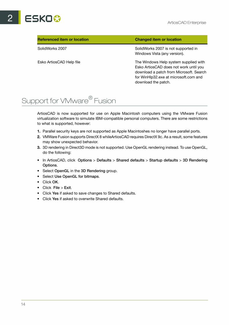
SolidWorks 2007 SolidWorks 2007 is not supported inWindows Vista (any version).
Esko ArtiosCAD Help file The Windows Help system supplied withEsko ArtiosCAD does not work until youdownload a patch from Microsoft. Searchfor WinHlp32.exe at microsoft.com anddownload the patch.
Support for VMware® Fusion
ArtiosCAD is now supported for use on Apple Macintosh computers using the VMware Fusionvirtualization software to simulate IBM-compatible personal computers. There are some restrictionsto what is supported, however:
1. Parallel security keys are not supported as Apple Macintoshes no longer have parallel ports.2. VMWare Fusion supports DirectX 8 whileArtiosCAD requires DirectX 9c. As a result, some features
may show unexpected behavior.3. 3D rendering in Direct3D mode is not supported. Use OpenGL rendering instead. To use OpenGL,
do the following:
• In ArtiosCAD, click Options > Defaults > Shared defaults > Startup defaults > 3D RenderingOptions.
• Select OpenGL in the 3D Rendering group.• Select Use OpenGL for bitmaps.• Click OK.• Click File > Exit.• Click Yes if asked to save changes to Shared defaults.• Click Yes if asked to overwrite Shared defaults.

3ArtiosCAD Enterprise
15
3. Installing and Configuring ArtiosCADEnterprise
ArtiosCAD Enterprise installs and operates differently than non-enterprise versions of ArtiosCADbecause of its improved Project and document management framework. Those changes arecontained in this chapter, and also in the ArtiosCAD Enterprise chapter in the ArtiosCAD User Guide.
If you are using a non-enterprise version of ArtiosCAD, please skip this chapter.
Installing ArtiosCAD Enterprise
The list below is a general guide to the steps required to install ArtiosCAD Enterprise. They will beexplained in greater detail in the following sections.
1. Install and configure WebCenter on its dedicated servers. Make sure to have access totheWebCenter and licensing documentation at http://help.esko.com, where you can alsodownload the PDF versions for printing and offline use. WebCenter and Licensing and Activationare listed in the Products section.
2. Run the board importer batch file.3. Load the ArtiosCAD Enterprise Defaults.4. In WebCenter, do the following:
• Configure companies and locations for the initial ArtiosCAD Enterprise users.• Create custom groups, if desired, for the initial ArtiosCAD Enterprise users.• Create the initial ArtiosCAD Enterprise users as Project Managers.• Invite new users to the Shared Defaults Project.
5. Install ArtiosCAD Enterprise on users’ computers.6. Start using ArtiosCAD Enterprise.
There are additional configuration tasks to do in WebCenter that will make ArtiosCAD Enterpriseeasier to use. They include:
• Assigning default boards to a location.• Creating characteristics, attribute categories, attributes, and restricted sets.
Finally, once everything is configured and working, you can set up a third tier of Defaults calledLocation Defaults. They sit between Shared Defaults and User Defaults. Location Defaults areconfigured independently for each location, although you can create a Template on which to basethem. For more information about using Location Defaults, see the information starting in the LocationDefaults Overview section later in this chapter.
Step 1 - Installing Esko WebCenter
The first step of installing ArtiosCAD Enterprise is to install WebCenter 10.2.

3ArtiosCAD Enterprise
16
Note: Have the WebCenter Complete Documentation manual handy for easy reference. It is in theUser Docs subfolder of the ArtiosCAD Enterprise folder on the media.
Installing WebCenter for use with ArtiosCAD Enterprise varies from the procedure in the WebCentermanual in that there are a few more steps required.
Note:
We do not recommend using an Express version of Microsoft SQL Server 2003 or 2008 if you willhave more than a few users or if you will be storing documents in the database itself (known asBLOBs) as well as WebCenter’s FileStore. If you plan on either of those situations, we recommendusing a full version of Microsoft SQL Server or Oracle.
The list below is a general overview to installing WebCenter. Refer to the WebCenter CompleteDocumentation manual for specific instructions. In case of a conflict, the information in the stepsbelow takes precedence over the steps in that manual.
1. Load the database server software (Microsoft SQL Server or Oracle) on the database server ifit is not already present. If you will be using a centralized corporate database server insteadof a dedicated WebCenter database server, you will either need to load database access andmanagement tools on the Application server, or map a drive to the Application server from thedatabase server, in order to run the database scripts batch file that builds the database schema.
2. If any users will be using the WebCenter Viewer to look at files, load the On-Board GraphicsEngine. Note that this will require a separate Automation Engine OBGE Server network licenseto be loaded on the Application server. For more information, see the WebCenter 10.2 CompleteDocumentation manual.
3. If you have an advanced database configuration and want to use BLOBs in your database,configure BLOBs in WebCenter. Now is the time to make this decision as migrating from a non-BLOB configuration to a BLOB configuration later is not recommended or supported. For moreinformation, see the Configuring BLOBs section.
4. On the Application server, do the following steps as a member of the local Administrators group:
a) Load ArtiosCAD Enterprise that is on the same media as WebCenter as an Advancedinstallation. Do not load a different version. If users will need to output PDF files, make sureyou have purchased the PDF option and that when selecting ArtiosCAD Programs to install,you select the PDF option.
b) Load the WebCenter Application server components. It is important to answer all questionscorrectly to avoid having to edit files later. You may receive a message about two installationprograms running at the same time. Click OK if you see this message.
c) Run the database scripts batch file appropriate for the type of database software you installed.You need to have the database access and management tools for your database programloaded on the Application server, or you need to do this from the database server with anetwork drive mapped to the Application server.
If you are using Oracle, you must have write access to the folder containing the databaseschema batch file as the batch file creates XML files used to create the database schema. Youmay want to copy the entire DatabaseSchema folder to the database server and run it locallyto ensure proper schema creation.
d) Start the WebCenter services (WebCenter App-X Application Container, WebCenter JBOSSApplication Server, WebCenter CAD-X Server, and WebCenter Search Crawler). You may wantto set them to start automatically.
5. On the Web server, do the following steps as a member of the local Administrators group:
3ArtiosCAD Enterprise
17
a) Make sure that Internet Information Services (IIS) is installed and working correctly. See thenext section for more information.
b) Load the WebCenter Web server components. It is important to answer all questions correctlyto avoid having to edit files later.
c) Start the WebCenter Tomcat service.d) Log in to WebCenter and change the admin password.
6. On the Application server, start the WebCenter CAD-X Server service.
Configuring BLOBs
ArtiosCAD Enterprise supports the use of BLOBs in the database. BLOBs are Binary Large OBjects- files stored as data in the database. Using BLOBs is transparent for the user.
When you configure ArtiosCAD Enterprise to use BLOBs, it also stores managed documents in theWebCenter FileStore as a cache to improve performance. If you delete a file from the FileStore, thenext time you save it in ArtiosCAD Enterprise, it will be recreated in the FileStore from the BLOB.
Note:
You should decide if you want to use BLOBs when you install WebCenter. Switching to using BLOBsafter having used ArtiosCAD Enterprise is not recommended or supported.
Editing appconfig.xml on the Application Server
To enable BLOBs, you must change a line in a configuration file on the Application server. On theApplication server:
1. Log in as Administrator or as a user with administrative privileges.
2. Make a backup copy of C:\Artios\WebCenter\config\appconfig.xml. This file will be onthe C: drive no matter where you installed WebCenter.
3. Open the file named in the previous step in a text editor such as Notepad.
4. Scroll down to <store_files_in_blob value="false"/> and change false to true.
5. Save the file and exit the text editor.
Restarting Services
Once you have changed appconfig.xml on the Application server, restart all the Applicationserver’s WebCenter services to start using BLOBs in ArtiosCAD Enterprise.
1. On the Application server, still logged in as Administrator or as a member of the localAdministrators group, open the Services applet in the Administrative Tools group in Control Panel.
2. Restart the following services by clicking each one and then clicking the Restart link:
a) WebCenter JBOSS Application Serverb) WebCenter CAD-X
3. Close the Services applet and log off the Application server.
ArtiosCAD Enterprise is now configured to use BLOBs. Note that WebCenter will keep copies ofmanaged documents in its FileStore to improve performance.
3ArtiosCAD Enterprise
18
Installing IIS7 on the Web Server
Installing IIS7 on the Web server for use with WebCenter and ArtiosCAD Enterprise has three steps:
1. Installing the software.2. Enabling 32-bit applications (only if the Web server is using a 64-bit operating system).3. Extending the size limit for uploaded files.
Install IIS on the Web Server Machine
If IIS is not installed on your web server, you need to install it. The procedure below explains howto install IIS7 on Windows Server 2008 R2.
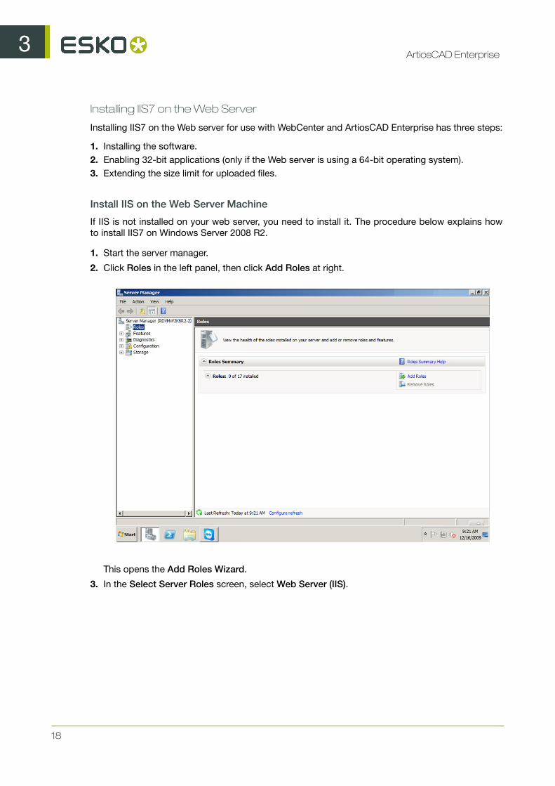
1. Start the server manager.
2. Click Roles in the left panel, then click Add Roles at right.
This opens the Add Roles Wizard.
3. In the Select Server Roles screen, select Web Server (IIS).

3ArtiosCAD Enterprise
19
If the wizard prompts you to add features required for the web server, do so.
4. In the Select Role Services screen:

3ArtiosCAD Enterprise
20
a) Select ASP, ISAPI Extensions and ISAPI Filters.
If the wizard prompts you to add role services required for ASP, do so.b) Select Logging Tools and Tracing.c) Select IIS 6 Management Compatibility.
5. In the Confirm Installation Selections screen, check the settings and click Install.
This installs the IIS 7 Role with the settings you have selected and the default settings.

3ArtiosCAD Enterprise
21
The Installation Results screen should show Installation succeeded.
Enable 32 Bit Applications
Note: Only do this if you have a 64 bit system!
1. In IIS, go to Application Pools and select the DefaultAppPool.
2. Click Advanced Settings..., then set the Enable 32 Bit Applications option to True and click OK.
3. Click Recycle... at right.
Extend the Upload Limitation
IIS7 has a limitation on how much you can upload at once (30 MB). You can change it to 2GB byfollowing these steps:
1. Open IIS 7 SnapIn.
2. Select the website for which you want enable large file uploads.
3. In the main window, double-click Request filtering.
4. Once the window is opened you may see a list of tabs (file name extensions, rules, hiddensegments…).
Regardless of the tab you select, right-click in the main window and select Edit Feature Settings.

3ArtiosCAD Enterprise
22
5. Modify the Maximum allowed content length (bytes): change the value to 2000000000 (a 2 and9 zeros) to be able to upload files close to 2GB.
Step 2 - Running the Board Importer Batch File
After you have loaded WebCenter and changed the admin password, the next step is to run theboard importer batch file. On the Web server, do the following:
1. Log in as a member of the local Administrators group.
2. Start a Command Prompt window.
3. Change directories to ..\WebCenter\WebServer\Boards.
4. Run the Board Import utility ImportBoards.bat which takes the following arguments.
a) -username name of the WebCenter user doing the import, usually admin.b) -password password of the WebCenter user doing the import.c) -url URL to the WebCenter server.d) -dir Directory containing the migration files (same directory as the batch file).e) -output Specifies the optional creation of an XML file with the returned status of the
procedure.
An average command would be something like this: ImportBoards -username admin -password adminpassword -url http://server/WebCenter_Inst -dir C:\Esko\Artios\WebCenter\WebServer\Boards
5. Press Enter after typing the command. The batch file will run and load the ArtiosCAD boardinformation into WebCenter.
Step 3 - Loading the Esko ArtiosCAD Defaults
After you have run the board import batch file, the next step is to install and run the ArtiosCADDefaults installer.
Note:
The system you use for loading the Defaults must be able to keep the Defaults on it. You will haveto follow the same process to load future Defaults and the new installation will reference the olderversion’s Defaults as part of its installation. We recommend using the Application server for thisprocess.
Note:
This procedure takes a significant amount of time. We recommend starting it and doing otherthings until it completes.
1. Log in to the Application server as a member of the local Administrators group.
2. Insert the ArtiosCAD Enterprise media into the drive.
The ArtiosCAD Enterprise installer should appear. If it does not, run setup.exe in the rootdirectory of the media.
3. Click the button next to Install ArtiosCAD Defaults.

3ArtiosCAD Enterprise
23
a) Choose the language in which the setup program will run and click OK.b) Click Next in the Welcome dialog box.c) Click I accept the terms in the license agreement and click Next.d) In the Defaults Language Choice dialog box, select the language of the Defaults to upload
to WebCenter and click Next. Only one language may be uploaded per session, so to installmore than one language, repeat this procedure.
e) Enter your WebCenter server URL, admin username, and admin password in the WebCenterServer Information dialog box and click Next.
f) In the Shared Defaults dialog box, you can choose a version of ArtiosCAD Standard Editionthat is the same version or earlier from which to merge Shared Defaults into Enterprise. Touse the delivered Shared Defaults, choose Use installed shared defaults; otherwise, chooseCopy shared defaults from this version and select the version. Click Next.
g) Click Install to begin the installation.
A progress indicator will appear.
4. Click Finish when the installation process is done.
Step 4 - Creating a New Company and Location
The next step is to create an entry for your company and location that will contain the users.
1. Log in to WebCenter as admin or as a member of the ADMINS group.
2. Click Admin > Companies > New Company.
3. Enter the information about the new company. Fields with asterisks next to them are required tohave information in them.
4. Click Create.
A status message saying the company was created successfully appears at the bottom of thepage.
To add more locations to this company, click the successful status message to edit the company,and then click Locations > New Location and enter the pertinent information for the new location.Click Add Location and repeat as desired.
Step 5 - Creating a New Group
This step is optional.
Group membership is an important administration and security consideration. Only two groups,ADMINS and USERS, are created by default when you install WebCenter. For efficient classificationof users, you may want to create different groups so that different users can easily have differentProject permissions. On the other hand, you might find it easier for all users to belong to one groupand to invite that one group to your Project templates. It all depends on if you want different groupsof multiple users to have different abilities.To create a new group, do the following:
1. Click Admin > Groups > New Group.
2. Enter the name of the group.
3ArtiosCAD Enterprise
24
3. Choose who will be able to see this group: All Project Managers, Administrators Only, orSelected Project Managers.
4. Click Continue.
5. In Step 2: Select Group Members, since you have not created any users yet, click Continue.
6. Is this new group visible to every Project Manager or only to Administrators:
• If yes, click Finish. The group is created.• If no, click Continue. Then, in Step 3: Assign group visibility to project manager(s), select the
Project Managers who can see this group and click Finish.
Project Managers with Full Visibility is unavailable, as they can see all groups. By default, groupmembers can see the group but you can still de-select the group members so that they don'tknow this group exists.
Step 6 - Creating New Users
The next step is to create users who will use ArtiosCAD Enterprise. Refer to the WebCenterdocumentation for more information.
1. Click Admin > Users > New User.
Step 1: User Info in the Create New User wizard appears.
2. Type the basic user information into the appropriate fields (Username, First Name, Last Name, ...).
Note: Required fields are indicated with an asterisk *.
3. Do you want to use LDAP authentication (single sign-on) for this user?
• If yes, enable the Use LDAP to Authenticate User option. This will allow the user to use hisregular Windows network user name and password to log on to WebCenter. Using LDAPrequires additional configuration in WebCenter. Please see the WebCenter documentation formore information.
• If no, provide the user’s initial Password and confirm it.
For ArtiosCAD Enterprise users, do not enable Require user to change the password at firstlogin.
4. Does the user need guaranteed access by means of a reserved license?
• If yes, enable the option User Has Guaranteed Access.• If no, leave the option disabled and proceed to the next step.
For more information on guaranteed access and its licensing implications, refer to the WebCenterdocumentation.
5. Does the user need special permissions in WebCenter? All ArtiosCAD Enterprise users should beat least Project Managers with Limited Visibility of Companies and Groups. If they are not, theadministrator will need to do additional configuration work described at the end of this procedure.
If the user needs... Select the option...
no special permissions and will not createProjects
Normal User

3ArtiosCAD Enterprise
25
If the user needs... Select the option...
Project Manager permissions, but only forProjects and users belonging to his or herown company
Project Manager with Limited Visibility ofCompanies and Groups.
Project Manager permissions on thecomplete system
Project Manager with Full Visibility
6. Does the user need the ability to create new task types in WebCenter? ArtiosCAD Enterprise usersdo not need to create task types.
• If yes, enable the option User Can Create Task Type.• If no, proceed to the next step.
7. To grant this user the ability to create other users without being a member of the ADMINS group,enable the option User Can Create User checkbox.
8. In Step 2: Assign to a Company, select a company and location to which you want to assignthe user. Note that this can be very important to filter the content, users, and Location Defaultsthe new user will be able to see.
9. If you:
• are creating a Normal User or a Project Manager with Full Visibility, the wizard is complete.Click Finish to create the user.
• are creating a Project Manager with Limited Visibility, click Continue and proceed to the nextstep.
10.In Step 3: Assign Visible Companies, select the companies that this user should be able to see,then click Continue.
The selection you make here filters the list of users in the next step so that this Project Manager cannever see users from the companies you did not select in this step. By default, only the companyof the Project Manager himself (the one you selected in the previous step) will be selected.
11.In Step 4: Assign Visible Groups, select the groups the user should be able to see, then clickFinish.
Only groups containing members that belong to one of the companies you assigned in theprevious step will show up in the list. In addition, some groups may be set to be visible to allusers (such as the ADMINS group).
A status message saying the user was created will appear. Stay on this page for the next step.
If a new user is not made a Project Manager, the user will not be able to use User Defaults unlessthe administrator does the following for each language and version of ArtiosCAD Enterprise that theuser will be using:
• Creates a Project for this user named ACadDefaults_N.NN_ll_username (where N.NN is theversion number, ll is the language code, and username is the user’s WebCenter username).
• Invites the user to the Project.• Uploads clientdflt.adf to the Project.• Grants the user View and Download permissions at the Project level. The user will not be able to
change the User Defaults with this level of permissions.• If the user needs to change the User Defaults, he or she must have Full permission at the Project
level.

3ArtiosCAD Enterprise
26
• Adds the user to the appropriate Location Defaults Project with at least View and Downloadpermissions. If the user needs to change the Location Defaults, he or she must have Fullpermission at the Project level.
Step 7 - Setting a New User’s Group Membership
Once you have created a new user, the next step is to assign that user to one or more groups. Evenif you did not create any custom groups, you should assign a new user to the USERS group.
1. While still on the Create New User page with the successful creation status message, Click Adduser to group(s).
2. In the Available Groups column, click each group to which you will add this new user. To selectmore than one group, hold down CTRL while clicking groups.
3. Click >> to assign the selected available groups to the user.
The user is added to the group(s) immediately.
Step 8 - Inviting New Users to the Shared Defaults Project
The next step is to invite new users to the Shared Defaults Project, which is Shared Defaults inArtiosCAD Enterprise. You can do this either individually for every user or once through Groupmembership if you added all users to the same group (such as USERS). Inviting them to the Projectmeans that they will be able to use the Defaults. In order for users to change Shared Defaults, theymust have Full permissions on the Project and be members of the ADMINS group.
Note:
All ArtiosCAD Enterprise users must be invited to the Shared Defaults Project. Users who are notinvited to the project will receive a UFANEX error when they launch ArtiosCAD Enterprise.
1. Click Admin > Project Management > Projects.
2. Click the name of the ACadDefaults_N.nn_ll_Shared Project (where N.nn is the version and llis the language) to which you are inviting the user.
3. Click Members on the Project menu.
4. Click Add members.
5. In Step 1 of 2: Select Users/Groups, check the checkboxes next to those users and groups toadd to the Project.
6. Click Continue.
7. In Step 2 of 2: Project or folder permission rules, assign at least Download permission for theProject and each folder in it. Invitees to Projects get View permission assigned automatically.
8. Click Finish.
The new invitees should now be able to log into ArtiosCAD Enterprise and start using it.

3ArtiosCAD Enterprise
27
Note:
Make sure to invite users or groups to the Shared Defaults Project for each version and languageof ArtiosCAD Enterprise they will use.
Step 9 - Installing ArtiosCAD Enterprise on a User’s Computer
To install ArtiosCAD Enterprise on a user’s computer, do the following:
1. Log in as Administrator or as a user with administrative privileges.
2. Put the ArtiosCAD Enterprise media into the computer’s media drive. It should automaticallylaunch the Setup program. If your drive is set to not AutoPlay, start Windows Explorer and double-click setup.exe in the root directory of the media.
3. In the Esko ArtiosCAD Setup dialog box, click the icon next to Install Esko ArtiosCAD N.nnll,where N.nnll is the version number and language.
The installer will launch and a few messages will display.
4. In the Welcome to the InstallShield Wizard for Esko ArtiosCAD N.nnll dialog box, click Next.
5. Read the Software License Agreement in its entirety and choose I accept the terms of the licenseagreement if you accept all the terms of the License Agreement. Click Next.
6. Choose a Typical installation and click Next. If you want to keep previous versions of the softwareor change the default location to save user files, choose Advanced and click Next.
a) In the User Files Folder dialog box, click Change to change the location for unmanaged userfiles from the location shown. Enter the new location and click OK.
b) In the Advanced Options dialog box, Keep Previous Versions is the default for previous versionhandling. It means that ArtiosCAD is installed using a version-specific folder and icon whichmatch the version and language of the installation, and all previous versions of ArtiosCADare kept. To change this setting, click Change. In the Previous Version Handling dialog box,Overwrite previous versions simply uses ArtiosCAD as the icon name and ArtiosCAD as thedirectory with no version number. It overwrites the prior version of ArtiosCAD if this is anupgrade and the previous version was installed to a non-version-specific directory. Once youhave chosen the option to use, click OK to return to the Advanced Options dialog box.
c) Click Next to continue.
7. In the Feature Selection dialog box, choose the features to install on the current machine. Foreach feature, click the icon in the drop-down list box next to it and choose the appropriate choice.Do not click Next when done, but rather proceed to the next numbered step.
a) Esko ArtiosCAD Licensing controls whether this machine is a license server or not. ForArtiosCAD Enterprise, the WebCenter Application server should be the licensing server, so thischoice should be set to This feature will not be available.
b) Esko ArtiosCAD Programs are the program files needed to run ArtiosCAD Enterprise. Youmust install these if you want to run ArtiosCAD Enterprise on the current machine. You mustleave this choice selected to install ArtiosCAD itself.
c) Contained within this group are optional components of ArtiosCAD Enterprise that requirepurchasing licenses for the corresponding modules: PDF Import/Export and 3D Importer.Refer to the printed license report that came with the media to determine which componentsto select. Installing software components without having the corresponding licenses wastesdisc space, but hinders operation if you purchase a license in the future. Not installing the

3ArtiosCAD Enterprise
28
software components but having the licenses for them results in features that do not functionwithin ArtiosCAD.
d) Esko Configuration Manager collects data from systems running the Esko Station InformationService and sends the collected data to EskoArtwork automatically for use by Supportpersonnel. It sends information only if you configure it to do so and leave it enabled. It isa great aid to Support personnel as they will have required information about your hardwareand licenses available should you need to call for assistance. Only one system per siteshould have the Esko Configuration Manager installed. Refer to the separate document ScopeConfiguration Manager 1.0 Software Installation and Configuration Manual on the ArtiosCADmedia (SCM_nn_SICFM.PDF in the User Docs folder) for more information.
8. While still in the Feature Selection dialog box, with one of the components to be installed selected,review the folder in which ArtiosCAD Enterprise will be installed, and click Change if desired. Inthe resulting Change Current Destination Folder dialog box, change the drive if desired, and clickOK to return to the Feature Selection dialog box. ArtiosCAD should always be installed to the\Esko\Artios folder on a local drive. Click Next.
9. Choose the type of licensing to use from the drop-down list box. You should have separateinformation that came with the media that describes your licensing. Click Next.
10.In the Ready to Install the Program dialog box, review the settings for correctness. If the settingsare incorrect, click Back and fix them. If they are correct, click Install.
11.If this system has other EskoArtwork products on it, you may be prompted to stop their licenseservices. Click Yes to proceed with the installation.
12.In the InstallShield Wizard Completed dialog box, click Finish.
If you are prompted to reboot the system, click Yes. It is very important that you reboot thesystem if prompted.
For this user to use ArtiosCAD Enterprise, you should have already followed major installation steps6 through 8. If not, perform them now. Once done, the user should be ready to use ArtiosCADEnterprise. Repeat for other users as needed.
Post-Installation Configuration Tasks
There are two post-installation configuration tasks you should do in WebCenter that make ArtiosCADEnterprise more useful in terms of proper categorization of Project information:
• Assign default boards to a location.• Create characteristics, attribute categories, attributes, and restricted sets.
Assigning Default Boards to a Location
When users create a design, they have to assign a board to it. Boards that are assigned to theirlocation are shown by default. If no boards are assigned to their location, every time they createa design, they have to click Show All Boards to view the actual boards in their folders; otherwise,ArtiosCAD Enterprise shows a list of empty folders.
To assign default boards to a location, do the following:
1. Log in to WebCenter as a member of the ADMINS group.
2. Click Admin > CAD > Boards.

3ArtiosCAD Enterprise
29
3. Expand the board tree by clicking the plus signs (+) in front of the categories.
4. To assign a particular board to a location, do the following:
a) Click its name.b) Check the checkbox to the left of the location to which you are assigning the board. You may
check more than one checkbox to assign the board to multiple locations.c) Click Finish.d) Click Boards to return to the Board tree.
CharacteristicsCharacteristics are descriptive tags that can be assigned to Projects and documents to make themeasier to find.
Characteristics are hierarchical. This means there can be different levels of characteristics for variousproduct lines so that you can drill down through the information to find the exact characteristicdesired when searching the database.
For example, you could create a master characteristic for Electronics, and then various sub-characteristics for types of appliances, entertainment equipment, or computers, and so forth. Theyare presented in a tree format - main categories with expandable branches. The characteristics treeconfigures the available characteristic names as well as how they are organized.
Create a Characteristic
1. Click Admin > Characteristics.
2. Do you want to add a primary characteristic (a main category) or a secondary characteristic?
• To add a primary characteristic, select the option button next to Root at the top of the treeand then click New Characteristic.
• To add a secondary characteristic, select the option button for the characteristic under whichto add the new one, and then click New Characteristic.
There can be up to 17 levels of characteristics or at most 256 characters for the entirecharacteristics path from the root characteristic to the deepest-level characteristic.
3. Enter the name of the characteristic in the Name field.
4. Click Create. The new characteristic appears in the list.
Edit or Delete a Characteristic
When deleting a characteristic, WebCenter checks if the characteristic or any of its childcharacteristics are assigned to any Projects or documents. If such a dependency is found, you areprompted to remove the dependency and delete anyway, or cancel the deletion.
1. Click Admin > Characteristics.
2. Do one of the following:
• To edit a characteristic, click its name in the tree structure. Type a new name in the EditCharacteristic page and click Save to confirm.
• To delete a characteristic, select it in the tree and click the Delete Characteristic link.
If there are no dependencies, it is deleted immediately. Note that any sub-characteristics ofthe selected characteristic will also be deleted.
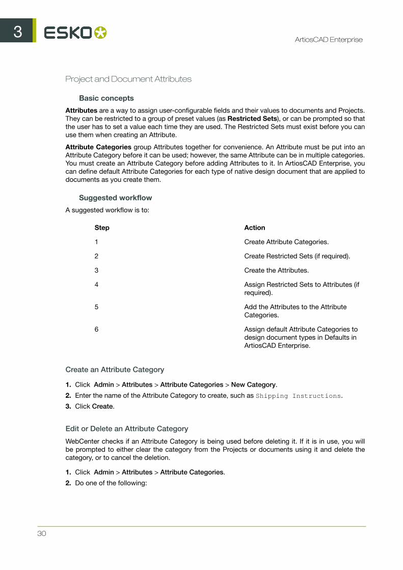
3ArtiosCAD Enterprise
30
Project and Document Attributes
Basic concepts
Attributes are a way to assign user-configurable fields and their values to documents and Projects.They can be restricted to a group of preset values (as Restricted Sets), or can be prompted so thatthe user has to set a value each time they are used. The Restricted Sets must exist before you canuse them when creating an Attribute.
Attribute Categories group Attributes together for convenience. An Attribute must be put into anAttribute Category before it can be used; however, the same Attribute can be in multiple categories.You must create an Attribute Category before adding Attributes to it. In ArtiosCAD Enterprise, youcan define default Attribute Categories for each type of native design document that are applied todocuments as you create them.
Suggested workflow
A suggested workflow is to:
Step Action
1 Create Attribute Categories.
2 Create Restricted Sets (if required).
3 Create the Attributes.
4 Assign Restricted Sets to Attributes (ifrequired).
5 Add the Attributes to the AttributeCategories.
6 Assign default Attribute Categories todesign document types in Defaults inArtiosCAD Enterprise.
Create an Attribute Category
1. Click Admin > Attributes > Attribute Categories > New Category.
2. Enter the name of the Attribute Category to create, such as Shipping Instructions.
3. Click Create.
Edit or Delete an Attribute Category
WebCenter checks if an Attribute Category is being used before deleting it. If it is in use, you willbe prompted to either clear the category from the Projects or documents using it and delete thecategory, or to cancel the deletion.
1. Click Admin > Attributes > Attribute Categories.
2. Do one of the following:

3ArtiosCAD Enterprise
31
• To edit an attribute category, click its name. Type a new name in the Edit Category page andclick Save to confirm.
• To add attributes to a category or remove them from it, click its name. Then use the chevron(<< or >>) buttons to move them between the Available Attributes and Current Attributescolumns.
Note: Moving Attributes between columns takes effect immediately.
• To delete an attribute category, select it, move the mouse over the menu symbol and clickDelete Category on the hover menu.
If there are no dependencies, it is deleted immediately. Note that any sub-attributes of theselected attribute will also be deleted.
Create a Restricted Set
1. Click Admin > Attributes > Restricted Sets.
2. Enter information in the fields as appropriate:
• Name. The name of the Restricted Set, up to 35 characters.• Type. The data type of the Restricted Set. There are six allowed types: Area, Distance, Float,
Integer, Text, Volume, and Weight. A float is a number containing a decimal point and an integeris a whole number. The labels in parentheses after the name of the type indicate the units ofmeasurement used in Imperial and metric systems.
• Value. An entry for the restricted set. Text values can be up to 255 characters long. Click Addto add the value to the set and clear the Value field. Enter as many values as desired, clickingAdd after each one.
3. Click Create to create the Restricted Set.
Edit a Restricted Set
1. Click Admin > Attributes > Restricted Sets.
2. Either filter or click Go to show the Restricted Sets.
3. Click the name of the Restricted Set to edit.
4. Change the name, or add and remove values as desired. You cannot change the type. If youremove a value, the next time you access a Project using the deleted value, you will be promptedto change it.
5. Click Change to make the changes.
Delete a Restricted Set
WebCenter checks if a Restricted Set is being used before deleting it. If it is in use, you will beprompted to either clear the Restricted Set from the Attribute using it, or to cancel the deletion.
1. Click Admin > Attributes > Restricted Sets.
2. Either filter or click Go to show the Restricted Sets.
3. Select the checkbox of the Restricted Set to delete.
4. Hover over the menu symbol and click Delete Restricted Set(s) from the hover menu.
5. Click OK when asked to confirm the deletion.

3ArtiosCAD Enterprise
32
6. If there are no dependencies, it is deleted immediately. If there are any dependencies, choose thedesired option and click OK.
Create an Attribute
1. Click Admin > Attributes > New Attribute.
2. Enter information in the fields as appropriate:
In the field... Fill in the...
Name name of the attribute (for example, Billable)
Description description of the attribute contents (forexample, Indicates whether work onthis project should be billed byfinance)
Type data type of the attribute. Floats are numberscontaining a decimal point (3.1415) andintegers are whole numbers (42).
Values choose Prompted if you want to allow theuser to enter any value, Calculated to enteran ArtiosCAD formula for calculating the valueof the Attribute when ArtiosCAD opens thedocument containing the Attribute (the valuesare read-only in WebCenter), or select aRestricted Set to limit the possible values. Tochoose a Restricted Set, it must be createdbefore defining the Attribute. Make sure thatthe type of the Restricted Set is the same asthe Attribute type.
3. Click Create.
Edit or Delete an Attribute
When deleting an attribute, WebCenter checks if the attribute or any of its child attributes areassigned to any Projects. If such a dependency is found, you are prompted to remove thedependency and delete anyway, or cancel the deletion.
1. Click Admin > Attributes.
2. Do one of the following:
• To edit an attribute, click its name. Type a new name in the Edit Attribute page and click Saveto confirm.
You cannot change the attribute type.• To delete one or more attributes, select the corresponding checkboxes, hover over the menu
symbol and click Delete Attribute(s) on the hover menu.
If there are no dependencies, it is deleted immediately.

3ArtiosCAD Enterprise
33
Assigning Default Attribute Categories to Document Types
ArtiosCAD Enterprise comes with three empty Attribute Categories: DEFAULT A3D CATEGORY,DEFAULT DESIGN CATEGORY, and DEFAULT MANUFACTURING CATEGORY. Create and addAttributes to these categories as described previously, or create your own Attribute Categories asdesired. Once you have the Attributes Categories populated as desired, do the following to assigndefault Attribute Categories to document types:
1. Launch ArtiosCAD Enterprise and log in as a member of the ADMINS group.
2. Click Options > Defaults.
3. Expand the Database Defaults catalog by clicking the plus sign (+) next to it.
4. Double-click Default Attribute Categories.
The Default Attributes Categories dialog box appears.
5. Select the desired categories from the drop-down list boxes and click OK.
6. Save and exit Defaults.
If you have added Attributes to the default categories but the drop-down list boxes are empty, orif you do not see the Attribute Categories you recently created, exit Defaults and use the CacheManager to update the Attributes table.
Configuring ArtiosCAD Enterprise
ArtiosCAD Enterprise gets its board information from the database. The Board and Flute browserslet you manage paper boards, plastic boards, and foams.

3ArtiosCAD Enterprise
34
Outputs in ArtiosCAD Enterprise may have their output directed to a Project in addition to a deviceor a file.
Using the Flute Browser
Use the Flute browser to create and edit flutes, which are the wavy papers glued between liners toform corrugated board. ArtiosCAD Enterprise comes with several predefined flutes.
Opening the Flute Browser
To open the Flute browser, do the following:
1. Launch ArtiosCAD Enterprise and log in as a member of the ADMINS group.
2. Click Database > Manage Boards > Flute browser.
The Flute browser opens.
The Flute Browser Toolbar
Shown below is the Flute browser toolbar.

3ArtiosCAD Enterprise
35
Button Action
Inserts a new flute.
Deletes the selected flute.
&
Toggles units between metric and Imperial.
Toggles display of the Details pane.
Working with Flutes
Viewing Flute Details
To view details about a flute:
You can... Double-click the flute to select it andopen the Details pane.
You can...
Click the Details pane toggle onthe toolbar and then select the flute.
The Flute browser will then look like this:
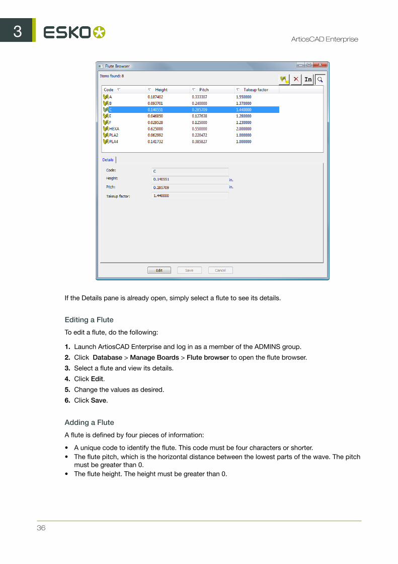
3ArtiosCAD Enterprise
36
If the Details pane is already open, simply select a flute to see its details.
Editing a Flute
To edit a flute, do the following:
1. Launch ArtiosCAD Enterprise and log in as a member of the ADMINS group.
2. Click Database > Manage Boards > Flute browser to open the flute browser.
3. Select a flute and view its details.
4. Click Edit.
5. Change the values as desired.
6. Click Save.
Adding a Flute
A flute is defined by four pieces of information:
• A unique code to identify the flute. This code must be four characters or shorter.• The flute pitch, which is the horizontal distance between the lowest parts of the wave. The pitch
must be greater than 0.• The flute height. The height must be greater than 0.

3ArtiosCAD Enterprise
37
• The take-up factor, which is the ratio between the length of the fluted paper and the length of theboard. If the flute were stretched out, it would always be longer than the paper encasing it. Thetake-up factor must be greater than 1.
To add a flute, do the following:
1. Launch ArtiosCAD Enterprise and log in as a member of the ADMINS group.
2. Click Database > Manage Boards > Flute browser to open the flute browser.
3. Click Insert on the toolbar.
4. In the Details pane, enter the code, the height, the pitch, and the takeup factor in the appropriatefields.
5. Click Insert.
The new flute will appear in the list.
Deleting a Flute
To delete a flute, do the following:
1. Launch ArtiosCAD Enterprise and log in as a member of the ADMINS group.
2. Click Database > Manage Boards > Flute browser to open the flute browser.
3. Select the desired flute.
4. Click Delete on the toolbar.
5. Click Yes to confirm the deletion.
The deleted flute is removed from the list.
Using the Board Browser
Use the Board browser to maintain the corrugated boards, folding carton boards, papers, and foamsused in ArtiosCAD Enterprise.
Opening the Board Browser
To open the Board browser, do the following:
1. Launch ArtiosCAD Enterprise and log in as a member of the ADMINS group.
2. Click Database > Manage Boards > Board browser.
The Board browser opens with all the catalogs closed. Click the plus sign next to each folder toopen it. Some folders are opened in the following example.

3ArtiosCAD Enterprise
38
The Board Browser Toolbar
Shown below is the Board browser toolbar.
Button Action
Inserts a new board.
Deletes the selected board.
&
Toggles units between metric and imperial.
Toggles display of the Details pane.

3ArtiosCAD Enterprise
39
Working with Boards
Viewing Board Details
To view details about a board:
You can... Double-click the board to select it andopen the Details pane.
You can...
Click the Details pane toggle onthe toolbar and then select the board.
The Board browser will then look like this:
If the Details pane is already open, simply select a board to view its Details.
Editing a Board
To edit a board, do the following:
1. Launch ArtiosCAD Enterprise and log in as a member of the ADMINS group.

3ArtiosCAD Enterprise
40
2. Click Database > Manage Boards > Board browser to open the board browser.
3. Select a board and view its details.
4. Click Edit.
5. Change the values as desired.
6. Click Save.
Creating a paper
Papers are the building blocks of boards so you must create them before you can create boards.
To create a new paper, first examine an existing paper to determine what information you will needto define the new paper. Papers are in their own folder in the Board browser. Usually the caliper,inside loss, outside gain, rounding value, basis weight, and basis cost are needed. You may also setinside and outside colors and other appearance attributes to the paper that appear in the optional3D module.
To create a new paper, do the following:
1. Launch ArtiosCAD Enterprise and log in as a member of the ADMINS group.
2. Click Database > Manage Boards > Board browser to open the board browser.
3. Open the Artios folder by clicking the plus sign next to it.
4. Click the word Papers to select it.
5. Click Insert on the toolbar.
The Details pane will automatically appear with the fields enabled for editing.

3ArtiosCAD Enterprise
41
6. Enter values in the fields on the Details tab as appropriate.
a) Board Code is the identifier used by the database to identify this new paper; each paper musthave a unique code.
b) Description is the description of the paper.c) Caliper is the thickness of the paper.d) Inside Loss and Outside Gain are the allowances used when folding the paper or when gluing
it together (such as in a glue flap). They are generally half the caliper.e) Rounding Value sets a value to which dimensions may be set to round to when constructing
a corrugated design. It is more relevant for boards as a whole rather than individual papers.f) Basis Weight is the weight of the paper in local currency and units of measurement.g) Basis Cost is the cost of the paper in local currency and units of measurement.h) Test Value is the amount of weight needed to break the material when performing very specific
standardized tests. It is more relevant for corrugated boards as a whole than individual papers.i) Test Code is the identifier used in correlation with the Test Value to show the strength of the
paper. It is more relevant for corrugated boards than individual papers.j) Weight and Cost in the Adhesive group should be set for the complete board definition, not
individual paper and flute definitions.
7. Leave the fields on the Papers tab blank, as they are not relevant.
8. On the Material Properties tab are fields to set the shininess, transparency, and inside and outsidecolors of the paper. These properties are only visible in the optional 3D module.

3ArtiosCAD Enterprise
42
a) Set the Shininess% and Transparency% fields as desired. The Transparency% field is aseparate setting from transparency mode in 3D and is not affected by that setting.
b) Surface colors for papers are split into three components: ambient color, which reflects theambient light; diffuse color, which reflects the movable lights in an airy, non-shiny way; andspecular color, which reflects movable lights for a shiny surface, with a shiny surface havinga white specular color and a dull surface a black specular color.
c) By default, the Material Properties tab only displays Diffuse color in Simple color mode. InSimple color mode, choose an RGB color by clicking Select color, or choose a CYMK color byclicking CYMK color. To set the other two colors, click Advanced color, and then click Selectcolor as desired. You may only set a CMYK color for the Diffuse color in Simple color mode.
d) The outermost Outside paper color is used to set the Outside board color if no other colorhas been manually chosen for the outside of the board. Likewise, the innermost Inside papercolor is used to set the Inside board color if no other color has been manually chosen for theinside of the board.
e) The ... button (Browse) is used in board definitions to calculate the color based on the materialscomprising the board. It is not relevant for papers.
9. On the Texture tab are fields to specify the graphics that may be used to represent the inside,outside, and edge textures of the paper. These properties are only visible in the optional 3Dmodule. Outside and inside textures are more relevant for boards, but may also be defined forpapers, while board edge textures do not apply to papers.
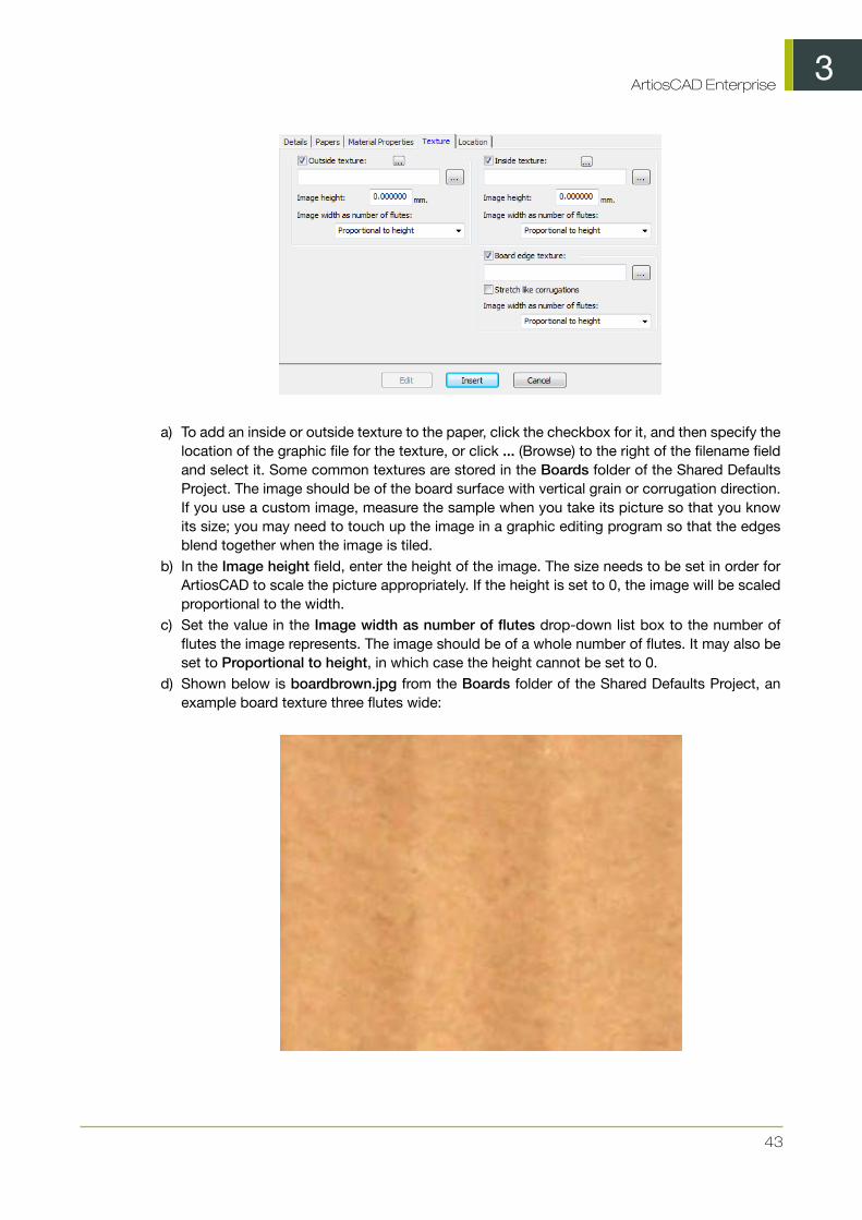
3ArtiosCAD Enterprise
43
a) To add an inside or outside texture to the paper, click the checkbox for it, and then specify thelocation of the graphic file for the texture, or click ... (Browse) to the right of the filename fieldand select it. Some common textures are stored in the Boards folder of the Shared DefaultsProject. The image should be of the board surface with vertical grain or corrugation direction.If you use a custom image, measure the sample when you take its picture so that you knowits size; you may need to touch up the image in a graphic editing program so that the edgesblend together when the image is tiled.
b) In the Image height field, enter the height of the image. The size needs to be set in order forArtiosCAD to scale the picture appropriately. If the height is set to 0, the image will be scaledproportional to the width.
c) Set the value in the Image width as number of flutes drop-down list box to the number offlutes the image represents. The image should be of a whole number of flutes. It may also beset to Proportional to height, in which case the height cannot be set to 0.
d) Shown below is boardbrown.jpg from the Boards folder of the Shared Defaults Project, anexample board texture three flutes wide:
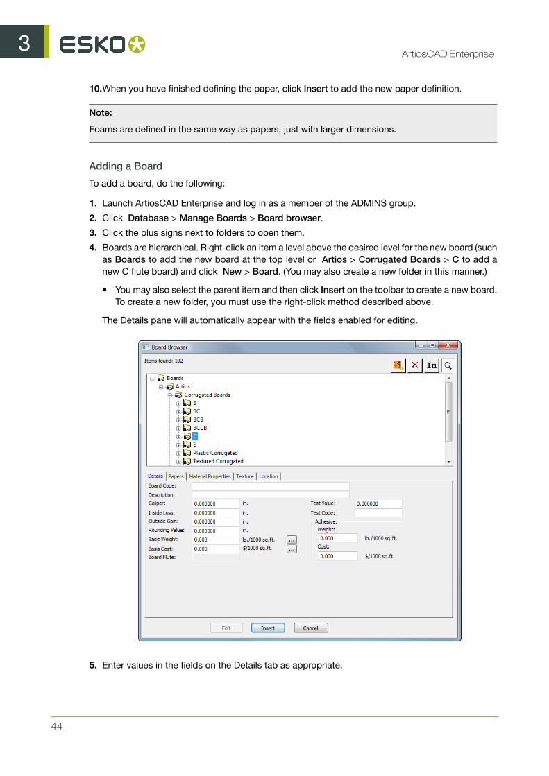
3ArtiosCAD Enterprise
44
10.When you have finished defining the paper, click Insert to add the new paper definition.
Note:
Foams are defined in the same way as papers, just with larger dimensions.
Adding a Board
To add a board, do the following:
1. Launch ArtiosCAD Enterprise and log in as a member of the ADMINS group.
2. Click Database > Manage Boards > Board browser.
3. Click the plus signs next to folders to open them.
4. Boards are hierarchical. Right-click an item a level above the desired level for the new board (suchas Boards to add the new board at the top level or Artios > Corrugated Boards > C to add anew C flute board) and click New > Board. (You may also create a new folder in this manner.)
• You may also select the parent item and then click Insert on the toolbar to create a new board.To create a new folder, you must use the right-click method described above.
The Details pane will automatically appear with the fields enabled for editing.
5. Enter values in the fields on the Details tab as appropriate.

3ArtiosCAD Enterprise
45
a) Board Code is the identifier used by the database to identify this new board; each board musthave a unique code.
b) Description is the description of the paper.c) Caliper is the thickness of the paper.d) Inside Loss and Outside Gain are the allowances used when folding the paper or when gluing
it together (such as in a glue flap). They are generally half the caliper.e) Rounding Value sets a value to which dimensions may be set to round to when constructing
a corrugated design. It is more relevant for boards as a whole rather than individual papers.f) Basis Weight is the weight of the board in the selected system of units of measurement.
Clicking the ... (Browse) button at the end of the field displays the Calculated Basis Weightdialog box. In this dialog box is an analysis of the calculated weight of the board based onthe papers used to make it. To replace a manually-entered weight with the calculated weight,click Accept.
g) Basis Cost is the cost of the board in local currency and units of measurement. As with theBasis Weight field, the ... (Browse) button at the end of the field displays an analysis of thecalculated cost of the board based on the papers used to make it. To replace a manually-entered cost with the calculated cost, click Accept.
h) Test Value is the amount of weight needed to break the material when performing very specificstandardized tests.
i) Test Code is the identifier used in correlation with the Test Value to show the strength of thepaper.
j) The Weight and Cost fields in the Adhesive group are the respective weight and cost of theadhesive for the board as a whole.
6. The Papers tab contains drop-down list boxes to select the liners and mediums that comprisethe board.
a) If you know it already, type the flute code of the new board in the Board Flute field. At theend of the field is a ... (Browse) button that opens the Calculated Flute dialog box. Use thisto calculate the flute code after defining the liners and mediums for the board. If it is a singleboard, expect a flute code like C. Double wall could be BC, while triple- and quadruple-wallwould comprise four letters.
b) Boards are defined sequentially from the outside inward. For example, you must select Liner 2before you may select Medium 2. You may not select Liner 2 and then jump directly to selectingLiner 4.

3ArtiosCAD Enterprise
46
c) Select liners and mediums in their respective drop-down list boxes. As you select a liner andthen a flute, the Flute drop-down list box for that pair becomes available. You must select aflute before the next liner becomes available for selection.
d) Complete the paper selection process with a liner.
7. On the Material Properties tab are fields to set the shininess, transparency, and inside and outsidecolors of the board. These properties are only visible in the optional 3D module.
a) Set the Shininess% and Transparency% fields as desired. The Transparency% field is aseparate setting from transparency mode in 3D and is not affected by that setting.
b) Surface colors for papers are split into three components: ambient color, which reflects theambient light; diffuse color, which reflects the movable lights in an airy, non-shiny way; andspecular color, which reflects movable lights for a shiny surface, with a shiny surface havinga white specular color and a dull surface a black specular color.
c) By default, the Material Properties tab only displays Diffuse color in Simple color mode. InSimple color mode, choose an RGB color by clicking Select color, or choose a CYMK color byclicking CYMK color. To set the other two colors, click Advanced color, and then click Selectcolor as desired. You may only set a CMYK color for the Diffuse color in Simple color mode.
d) The outermost Outside paper color is used to set the Outside board color if no other colorhas been manually chosen for the outside of the board. Likewise, the innermost Inside papercolor is used to set the Inside board color if no other color has been manually chosen for theinside of the board.
e) The ... button (Browse) calculates the color based on the materials comprising the board. ClickYes to use the color of the paper; click No to use the color of the current board definition.
8. On the Texture tab are fields to specify the graphics that may be used to represent the inside,outside, and edge textures of the board. These properties are visible only in the optional 3Dmodule.
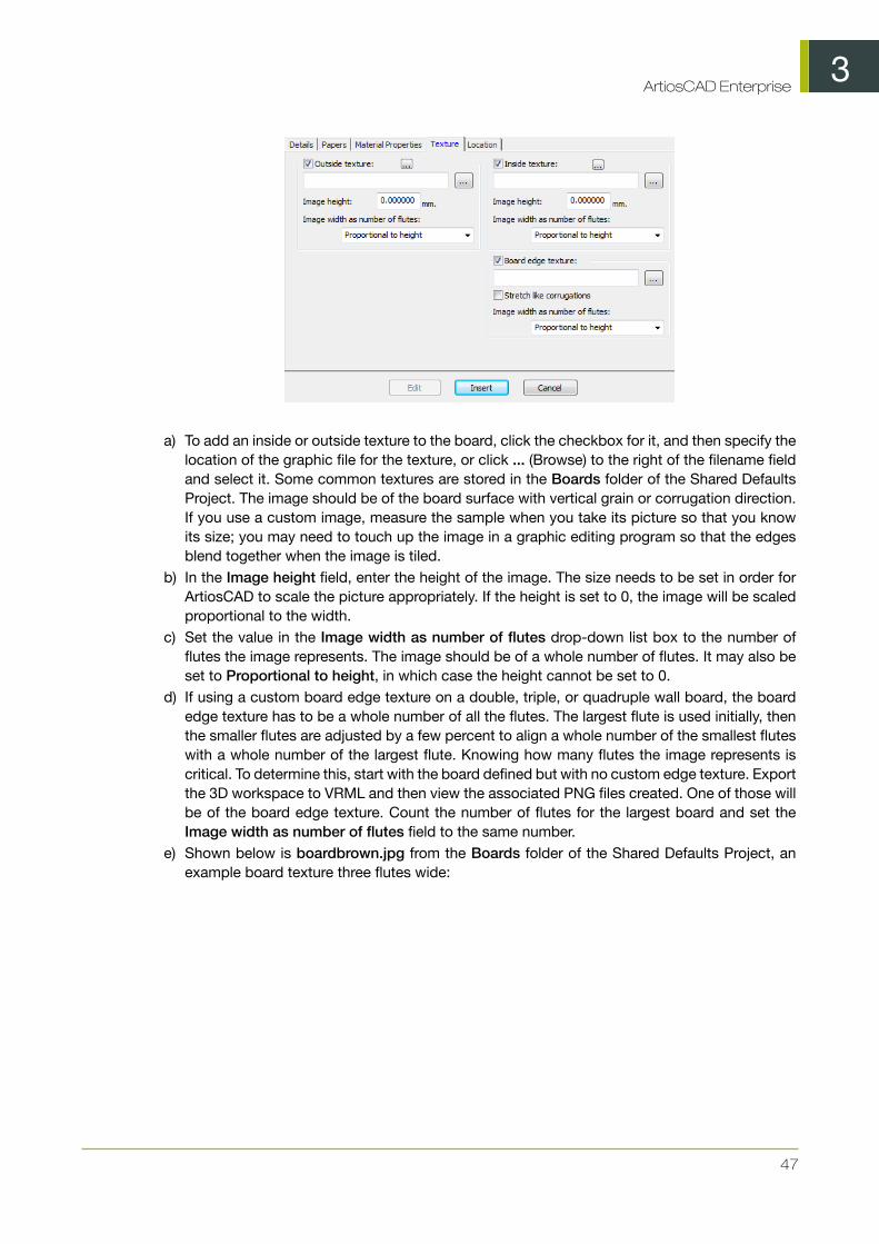
3ArtiosCAD Enterprise
47
a) To add an inside or outside texture to the board, click the checkbox for it, and then specify thelocation of the graphic file for the texture, or click ... (Browse) to the right of the filename fieldand select it. Some common textures are stored in the Boards folder of the Shared DefaultsProject. The image should be of the board surface with vertical grain or corrugation direction.If you use a custom image, measure the sample when you take its picture so that you knowits size; you may need to touch up the image in a graphic editing program so that the edgesblend together when the image is tiled.
b) In the Image height field, enter the height of the image. The size needs to be set in order forArtiosCAD to scale the picture appropriately. If the height is set to 0, the image will be scaledproportional to the width.
c) Set the value in the Image width as number of flutes drop-down list box to the number offlutes the image represents. The image should be of a whole number of flutes. It may also beset to Proportional to height, in which case the height cannot be set to 0.
d) If using a custom board edge texture on a double, triple, or quadruple wall board, the boardedge texture has to be a whole number of all the flutes. The largest flute is used initially, thenthe smaller flutes are adjusted by a few percent to align a whole number of the smallest fluteswith a whole number of the largest flute. Knowing how many flutes the image represents iscritical. To determine this, start with the board defined but with no custom edge texture. Exportthe 3D workspace to VRML and then view the associated PNG files created. One of those willbe of the board edge texture. Count the number of flutes for the largest board and set theImage width as number of flutes field to the same number.
e) Shown below is boardbrown.jpg from the Boards folder of the Shared Defaults Project, anexample board texture three flutes wide:

3ArtiosCAD Enterprise
48
f) To specify a graphic for the board edge texture, check the Board edge texture checkbox,then specify the filename of the graphic file for the texture, or click ... (Browse) to the right ofthe filename field and select it. Some common textures, for example paper corrugated edges,plastic corrugated edges, and paper hexacomb flutes, are stored in the Boards folder of theShared Defaults Project. The height of the image for a corrugated board should be the boardcaliper, and the width should be a whole number of flute pitches. Folding carton boards usean image width proportional to the height.
g) If no texture is specified for a corrugated board edge, a default picture based on the heightand pitch of the flutes is used.
h) Stretch like corrugations stretches the picture of the board edge texture depending on itsangle to the grain/corrugation direction. If this option is not selected, the board edge textureis repeated evenly.
i) Shown below is a picture of the default board edge texture with Stretch Like Corrugationsturned on in a design in 3D:
j) Shown below is a picture of the BrownB board in the Textured Corrugated folder with StretchLike Corrugations turned off in a design in 3D:
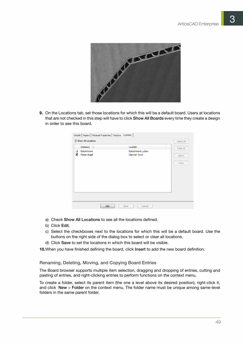
3ArtiosCAD Enterprise
49
9. On the Locations tab, set those locations for which this will be a default board. Users at locationsthat are not checked in this step will have to click Show All Boards every time they create a designin order to see this board.
a) Check Show All Locations to see all the locations defined.b) Click Edit.c) Select the checkboxes next to the locations for which this will be a default board. Use the
buttons on the right side of the dialog box to select or clear all locations.d) Click Save to set the locations in which this board will be visible.
10.When you have finished defining the board, click Insert to add the new board definition.
Renaming, Deleting, Moving, and Copying Board Entries
The Board browser supports multiple item selection, dragging and dropping of entries, cutting andpasting of entries, and right-clicking entries to perform functions on the context menu.
To create a folder, select its parent item (the one a level above its desired position), right-click it,and click New > Folder on the context menu. The folder name must be unique among same-levelfolders in the same parent folder.
3ArtiosCAD Enterprise
50
To rename a folder, select it, right-click it, click Rename on the context menu, enter the new name,and press Enter.
To delete a folder, first make sure it is empty, and then select it, right-click it, and click Delete on thecontext menu. You may not delete a non-empty folder.
To rename a board, edit it and change its description. This change will not be communicated backinto unmanaged documents using this board.
To move a folder or a board, drag it from one location to another.
To copy a board definition, select it, right-click it, and click Copy on the context menu. Right-clickthe folder into which it will be pasted and click Paste on the context menu. When the board is pastedinto the new folder, the current system time will be appended to the board code to maintain boardcode uniqueness.
Defaults
Defaults for ArtiosCAD Enterprise have only a few operational differences from other versions ofArtiosCAD.
• All users must be invited to the Shared Defaults Project for each version and language ofArtiosCAD Enterprise they will be using. See the major Step 8 section of the installationinstructions for more information.
• For users other than admin to edit Shared Defaults, they must have Full permissions on the SharedDefaults Project and be members of the ADMINS group. To create or change Location Defaultsor User Defaults, they do not have to be members of ADMINS, but they must have View, Add,Update, and Lock permissions on the entire Project.
• As a best practice, we strongly recommend that you place new Defaults reference documentsinto the ServerLib folder (or a new unique user-defined folder) of the Shared Defaults Project fordocuments which need to be shared by all users. Please note that document names must beunique within a Project. For new Defaults reference documents which will only be used by you,place these in a new user-defined folder of your User Defaults Project. If you must change anexisting ArtiosCAD-installed Defaults reference document, we recommended that you copy it asa new document to the ServerLib folder and then update the Defaults to reflect the new documentname. Following these recommendations gives ArtiosCAD Enterprise the best chance of properlymanaging upgrades.
• If you change the username of a user, you must change the name of that user’s associated Defaultsproject to match.
Browser Options
You can set browser options by clicking Options > Defaults > Browser Settings > GeneralInformation. As admin you can change the Shared Defaults, but in most cases as any user you canchange your own User Defaults.

3ArtiosCAD Enterprise
51
Click OK to return to Defaults once you have set the options as desired.
General Database Options
You can set database options by clicking Options > Defaults > Database Defaults > GeneralOptions . As admin you can change the Shared Defaults and Location Defaults, but in most casesas any user you can change your own User Defaults.

3ArtiosCAD Enterprise
52
The options in the Database Information Dialog Options group control when you are prompted toenter database information about a document: when you create it, when you save it, both, or neither.If you do not select either option, users must click Database > Information while working on adocument to set its database information.

3ArtiosCAD Enterprise
53
In the Board Options group, you can choose to check to see if a board code has changed whenusers open documents, and you can choose how they are sorted in the Board Catalog.
The options in the Cache Options group control how often ArtiosCAD Enterprise updates the cache.See the discussion on using the cache manager in the User Guide for more information about thecache.
In the Document Thumbnail Options group, Create document thumbnails on server controlswhether ArtiosCAD Enterprise creates document thumbnails (deselected, the default choice) or ifWebCenter creates the thumbnails (selected).
Choose the thumbnail format in the Design Thumbnail Format group.
The New Project Options group has a Template drop-down list box. Use this to set the defaultTemplate ArtiosCAD will use for new Projects you create through the browser. However, this doesnot apply to Projects used for Defaults.
The settings in the Comment Options group control how ArtiosCAD manages comments whensaving a managed document.
To turn on the automatic commenting, check Preseed comment from previous version. This alsoenables the options in the Initial Comment group.
Use document description copies the document description to the comment field. If there is nodocument description, ArtiosCAD will prompt you for a comment. This will also cause the Projectdescription to seed the document description when you save a managed document for the first timeso that on the next save, the comment will be able to be seeded from the description.
User defined lets you enter a custom string that ArtiosCAD will use for the first comment.
Sending an Output to a Project
In ArtiosCAD Enterprise, you can direct an Output to go to a Project instead of a device or file.
Destination Tab in an Output Definition
Outputs that create files can send those files to Projects rather than directories by choosing theappropriate options on the Destinations tab.

3ArtiosCAD Enterprise
54
When you select Output To Project, many options become available for setting Project and documentnames and properties. If you choose any of the prompt options, when you run this Output, the ProjectBrowser appears so you can navigate to the desired Project, set the document and folder names,and enter any prompted information.
If Automatically Open is selected in an Output that goes to a Project, a temporary version of theOutput is downloaded to your computer and the appropriate program for the type of Output opens it.In the example above, the PDF file is saved to the Project, and then a temporary copy is downloadedand opened by the application registered to open PDFs on your system.
Setting the Title Bar Display Options
You can choose which revision and version information ArtiosCAD shows in the title bar. The Title BarOptions dialog box in Options > Defaults > Startup defaults presents different formatting options.Choose the preferred option and click OK.
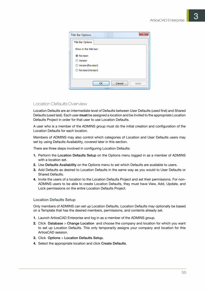
3ArtiosCAD Enterprise
55
Location Defaults Overview
Location Defaults are an intermediate level of Defaults between User Defaults (used first) and SharedDefaults (used last). Each user must be assigned a location and be invited to the appropriate LocationDefaults Project in order for that user to use Location Defaults.
A user who is a member of the ADMINS group must do the initial creation and configuration of theLocation Defaults for each location.
Members of ADMINS may also control which categories of Location and User Defaults users mayset by using Defaults Availability, covered later in this section.
There are three steps involved in configuring Location Defaults:
1. Perform the Location Defaults Setup on the Options menu logged in as a member of ADMINSwith a location set.
2. Use Defaults Availability on the Options menu to set which Defaults are available to users.3. Add Defaults as desired to Location Defaults in the same way as you would to User Defaults or
Shared Defaults.4. Invite the users of a location to the Location Defaults Project and set their permissions. For non-
ADMINS users to be able to create Location Defaults, they must have View, Add, Update, andLock permissions on the entire Location Defaults Project.
Location Defaults Setup
Only members of ADMINS can set up Location Defaults. Location Defaults may optionally be basedon a Template that has the desired members, permissions, and contents already set.
1. Launch ArtiosCAD Enterprise and log in as a member of the ADMINS group.
2. Click Database > Change Location and choose the company and location for which you wantto set up Location Defaults. This only temporarily assigns your company and location for thisArtiosCAD session.
3. Click Options > Location Defaults Setup.
4. Select the appropriate location and click Create Defaults.
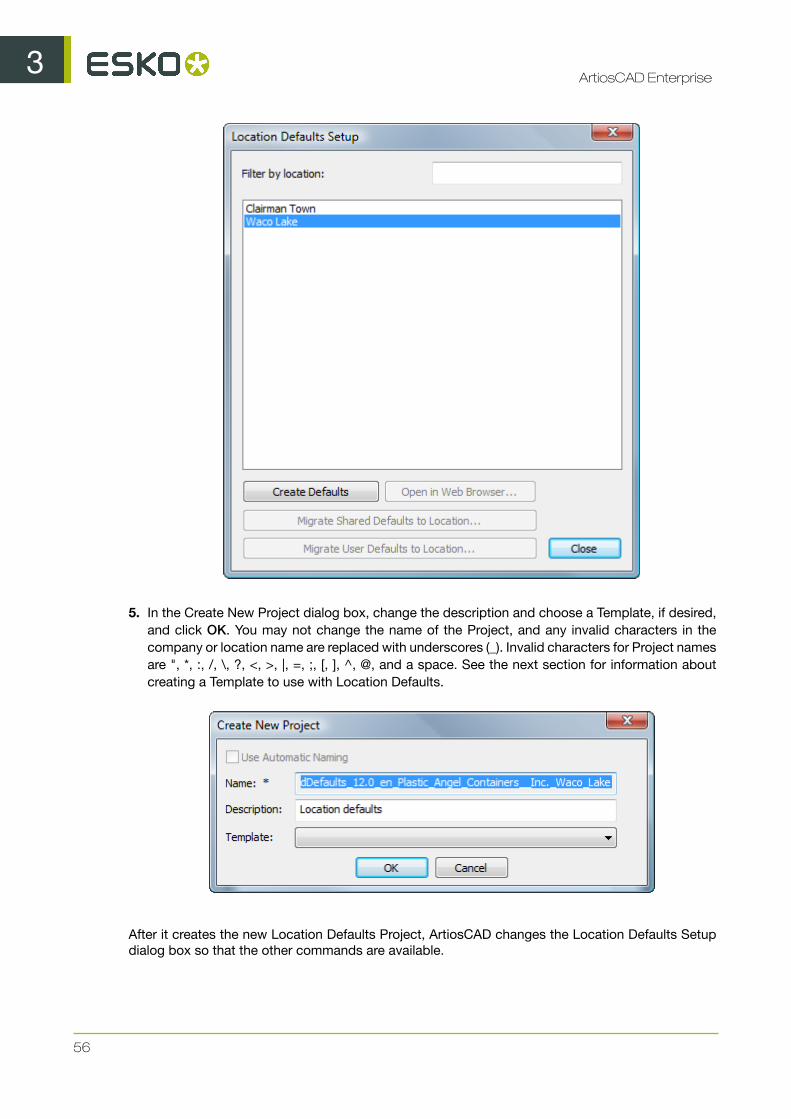
3ArtiosCAD Enterprise
56
5. In the Create New Project dialog box, change the description and choose a Template, if desired,and click OK. You may not change the name of the Project, and any invalid characters in thecompany or location name are replaced with underscores (_). Invalid characters for Project namesare ", *, :, /, \, ?, <, >, |, =, ;, [, ], ^, @, and a space. See the next section for information aboutcreating a Template to use with Location Defaults.
After it creates the new Location Defaults Project, ArtiosCAD changes the Location Defaults Setupdialog box so that the other commands are available.

3ArtiosCAD Enterprise
57
Open in Web Browser opens this Location Defaults Project in WebCenter using your default Webbrowser. You can then invite members, configure permissions, and so forth.
You can also migrate existing ArtiosCAD Standard Edition Shared Defaults or User Defaults intoLocation Defaults. Note that for User Defaults, you must currently be using the machine holding theUser Defaults in order to migrate them.
Now when you open Defaults in ArtiosCAD, you can add items to the Location Defaults pane just asyou would for Shared Defaults or User Defaults.
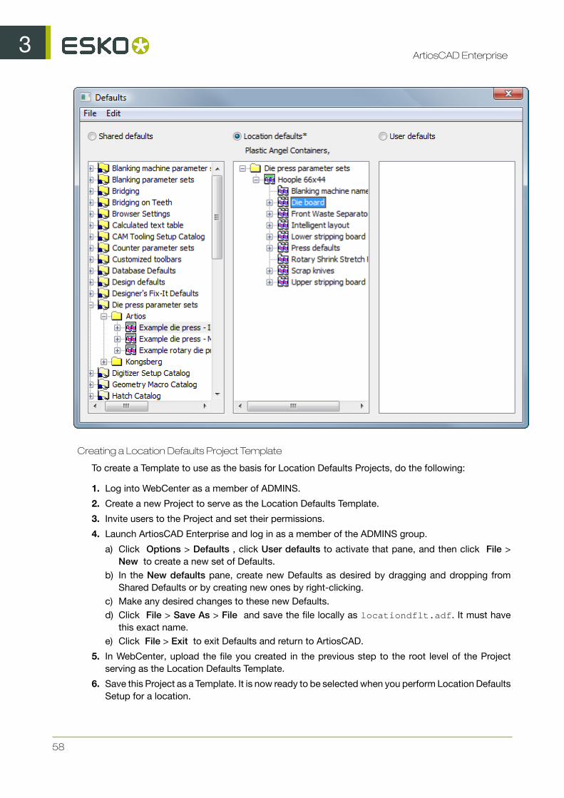
3ArtiosCAD Enterprise
58
Creating a Location Defaults Project Template
To create a Template to use as the basis for Location Defaults Projects, do the following:
1. Log into WebCenter as a member of ADMINS.
2. Create a new Project to serve as the Location Defaults Template.
3. Invite users to the Project and set their permissions.
4. Launch ArtiosCAD Enterprise and log in as a member of the ADMINS group.
a) Click Options > Defaults , click User defaults to activate that pane, and then click File >New to create a new set of Defaults.
b) In the New defaults pane, create new Defaults as desired by dragging and dropping fromShared Defaults or by creating new ones by right-clicking.
c) Make any desired changes to these new Defaults.d) Click File > Save As > File and save the file locally as locationdflt.adf. It must have
this exact name.e) Click File > Exit to exit Defaults and return to ArtiosCAD.
5. In WebCenter, upload the file you created in the previous step to the root level of the Projectserving as the Location Defaults Template.
6. Save this Project as a Template. It is now ready to be selected when you perform Location DefaultsSetup for a location.

3ArtiosCAD Enterprise
59
Migrating Defaults from ArtiosCAD Standard Edition to ArtiosCAD Enterprise
After you have set up Location Defaults, you can choose to migrate Shared Defaults or User Defaultsto the new Location Defaults.
Note:
Migrating existing Shared Defaults or User Defaults to Location Defaults will overwrite any existingLocation Defaults. It is a good idea if your current Location Defaults have data in them to back upyour Location Defaults using the browser. Drag the current Location Defaults Project to a location inthe Explorer node before you begin so that you have them as a backup.
1. Still in the Location Defaults Setup dialog box, click either Migrate Shared Defaults to Locationor Migrate User Defaults to Location. Note that the potential User Defaults must be from thecurrent machine.
2. Click Yes in the warning dialog box to migrate the Location Defaults.
3. in the Defaults Migration Dialog box, choose the version of ArtiosCAD containing the desiredDefaults and click OK. This process may not be canceled or aborted, so proceed with caution ifyou are unsure and click Cancel if you have any doubts.
4. A progress bar will appear as ArtiosCAD uploads the Defaults to WebCenter.
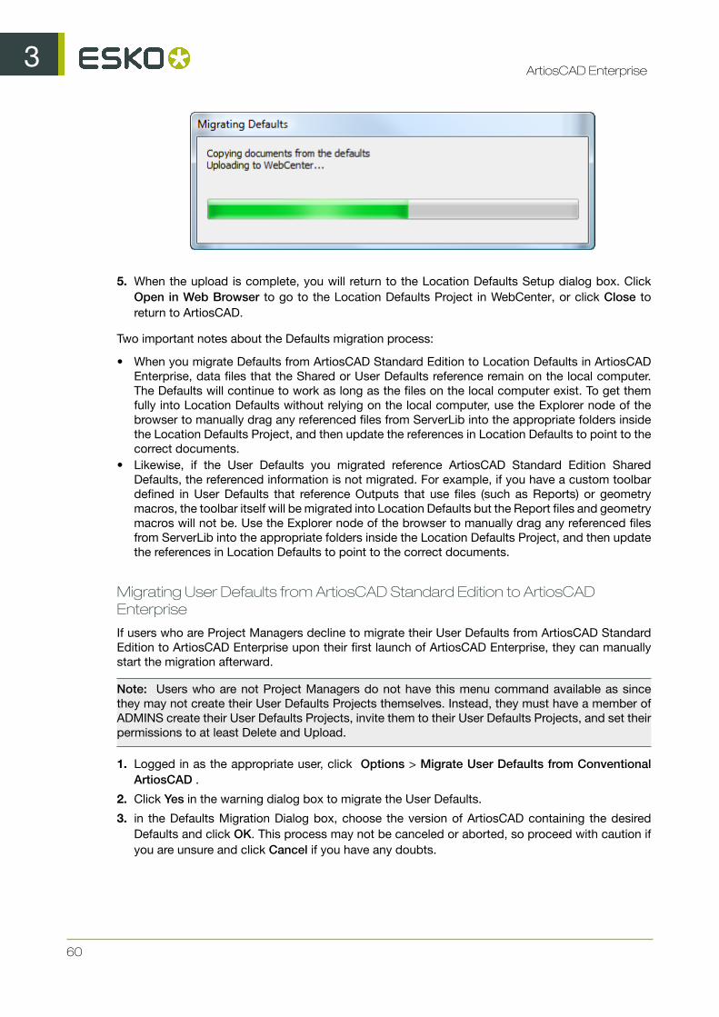
3ArtiosCAD Enterprise
60
5. When the upload is complete, you will return to the Location Defaults Setup dialog box. ClickOpen in Web Browser to go to the Location Defaults Project in WebCenter, or click Close toreturn to ArtiosCAD.
Two important notes about the Defaults migration process:
• When you migrate Defaults from ArtiosCAD Standard Edition to Location Defaults in ArtiosCADEnterprise, data files that the Shared or User Defaults reference remain on the local computer.The Defaults will continue to work as long as the files on the local computer exist. To get themfully into Location Defaults without relying on the local computer, use the Explorer node of thebrowser to manually drag any referenced files from ServerLib into the appropriate folders insidethe Location Defaults Project, and then update the references in Location Defaults to point to thecorrect documents.
• Likewise, if the User Defaults you migrated reference ArtiosCAD Standard Edition SharedDefaults, the referenced information is not migrated. For example, if you have a custom toolbardefined in User Defaults that reference Outputs that use files (such as Reports) or geometrymacros, the toolbar itself will be migrated into Location Defaults but the Report files and geometrymacros will not be. Use the Explorer node of the browser to manually drag any referenced filesfrom ServerLib into the appropriate folders inside the Location Defaults Project, and then updatethe references in Location Defaults to point to the correct documents.
Migrating User Defaults from ArtiosCAD Standard Edition to ArtiosCADEnterprise
If users who are Project Managers decline to migrate their User Defaults from ArtiosCAD StandardEdition to ArtiosCAD Enterprise upon their first launch of ArtiosCAD Enterprise, they can manuallystart the migration afterward.
Note: Users who are not Project Managers do not have this menu command available as sincethey may not create their User Defaults Projects themselves. Instead, they must have a member ofADMINS create their User Defaults Projects, invite them to their User Defaults Projects, and set theirpermissions to at least Delete and Upload.
1. Logged in as the appropriate user, click Options > Migrate User Defaults from ConventionalArtiosCAD .
2. Click Yes in the warning dialog box to migrate the User Defaults.
3. in the Defaults Migration Dialog box, choose the version of ArtiosCAD containing the desiredDefaults and click OK. This process may not be canceled or aborted, so proceed with caution ifyou are unsure and click Cancel if you have any doubts.

3ArtiosCAD Enterprise
61
4. A progress bar will appear as ArtiosCAD uploads the Defaults to WebCenter and will disappearwhen the process is complete.
Always Showing All Boards
When users do not have default boards assigned to their locations, when they create a new design orlook at the Board Information dialog box, they will not see any boards. To solve this problem, Alwaysshow all in boards selection in the Default boards catalog in Design defaults is enabled by default.

3ArtiosCAD Enterprise
62
Turn this option off after you have assigned each location a default board set, else toggling ShowAll Boards will not have much effect.
Defaults Availability overview
Defaults Availability on the Options menu gives members of ADMINS control over the types ofDefaults users may create and use in Location Defaults and User Defaults. For example, you maywant to force users to use a particular die press parameter set and not let users create new diepress parameter sets or modify the existing die press parameter set. Setting the Project permissionsappropriately prevents the modification of the die press parameter set in Shared Defaults, and usingthe settings in Defaults Availability can prevent them from creating a new parameter set in UserDefaults that would take precedence over the ones in Location Defaults or Shared Defaults.
Defaults Availability has two modes. As a member of ADMINS, you can:
• set the availability of items in Location Defaults for all locations of all companies• set the availability of items in User Defaults for multiple locations of your assigned company
simultaneously. If you do not have a company assigned, this option will be unavailable; clickDatabase > Change Location to set a temporary location before using Defaults Availability.
Setting Defaults Availability for Location Defaults
To set the availability of defaults in Location Defaults for all companies and all locations, do thefollowing:
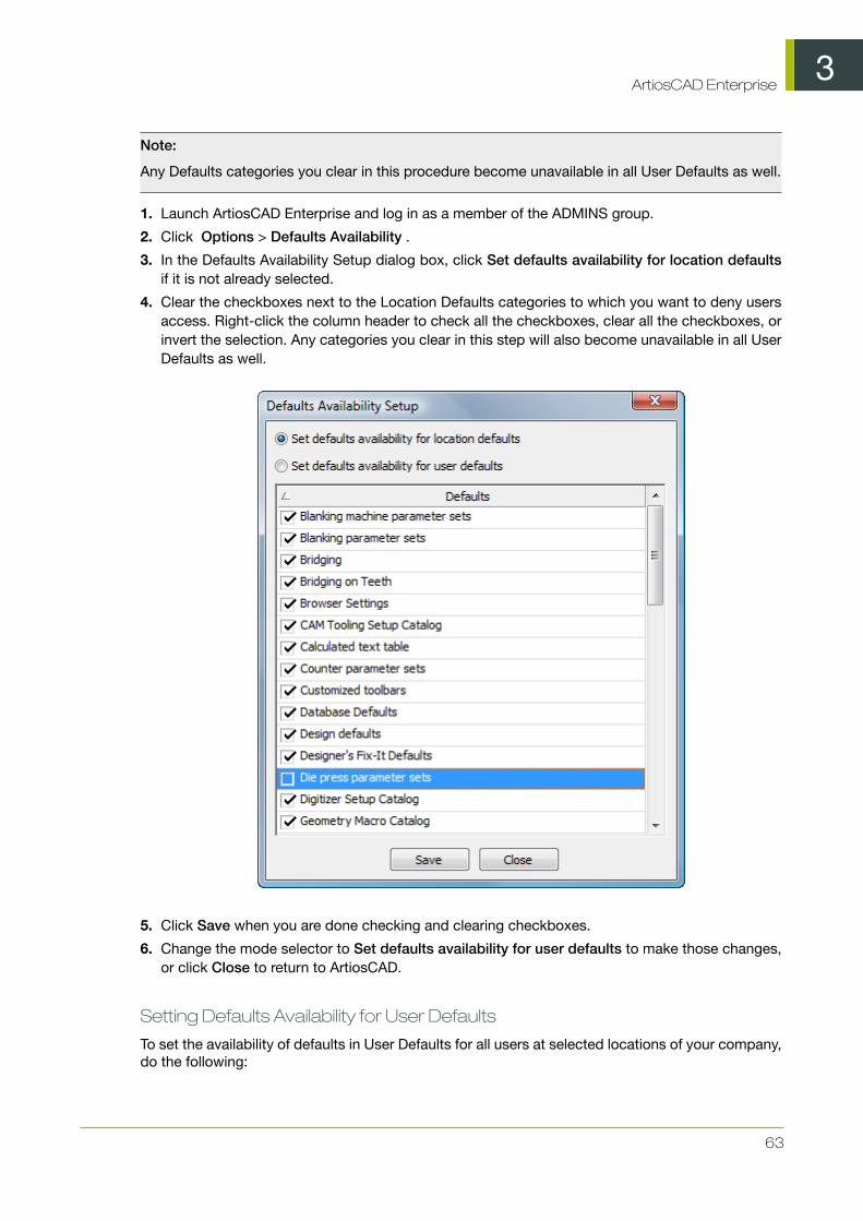
3ArtiosCAD Enterprise
63
Note:
Any Defaults categories you clear in this procedure become unavailable in all User Defaults as well.
1. Launch ArtiosCAD Enterprise and log in as a member of the ADMINS group.
2. Click Options > Defaults Availability .
3. In the Defaults Availability Setup dialog box, click Set defaults availability for location defaultsif it is not already selected.
4. Clear the checkboxes next to the Location Defaults categories to which you want to deny usersaccess. Right-click the column header to check all the checkboxes, clear all the checkboxes, orinvert the selection. Any categories you clear in this step will also become unavailable in all UserDefaults as well.
5. Click Save when you are done checking and clearing checkboxes.
6. Change the mode selector to Set defaults availability for user defaults to make those changes,or click Close to return to ArtiosCAD.
Setting Defaults Availability for User Defaults
To set the availability of defaults in User Defaults for all users at selected locations of your company,do the following:

3ArtiosCAD Enterprise
64
Note: If you do not have a company assigned, this option will be unavailable; click Database >Change Location to set a temporary location before using Defaults Availability.
1. Launch ArtiosCAD Enterprise and log in as a member of the ADMINS group.
2. Click Options > Defaults Availability .
3. In the Defaults Availability Setup dialog box, click Set defaults availability for user defaults.
4. Select one more or locations containing the users to whom you are denying access.
5. Clear the checkboxes next to the User Defaults categories to which you want to deny usersaccess. Right-click the column header to check all the checkboxes, clear all the checkboxes, orinvert the selection.
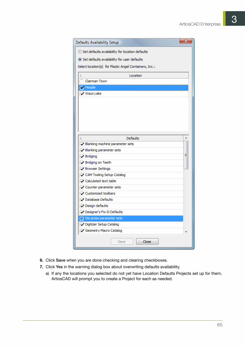
3ArtiosCAD Enterprise
65
6. Click Save when you are done checking and clearing checkboxes.
7. Click Yes in the warning dialog box about overwriting defaults availability.
a) If any the locations you selected do not yet have Location Defaults Projects set up for them,ArtiosCAD will prompt you to create a Project for each as needed.

3ArtiosCAD Enterprise
66
8. ArtiosCAD displays a progress bar as it makes the changes to Defaults.
9. Click Close in the Defaults Availability Setup dialog box to return to ArtiosCAD.
Configuring the Automatic Naming Templates
There are three places in WebCenter to configure automatic naming - in Admin > Preferences >General for Projects and in Admin > Preferences > Document Types for documents. For Templates,to override the system default autonaming configuration for Projects and documents inside thatTemplate, it is in Admin > Projects > Templates > <template> > Configure > Project Creation orDocument Creation .
The naming templates control the prefix, body, and suffix ArtiosCAD Enterprise uses when it namesProjects and documents automatically. The body is a counter that increments independently for eachProject or document.
To configure the naming templates, do the following:
1. Start a Web browser and log in to WebCenter as a member of the ADMINS group.
2. For Projects, click Admin > Preferences > General .
a) Check Use Automatic Naming for Creation of Blank Projects.b) In the Project Autoname Generation section, enter the building blocks of the prefix and suffix
in the appropriate fields. Make sure to use spaces or other delimiters (not commas) betweenthe fields, else they will run together and the counter will not increment correctly.
c) For a list of the building blocks you can use for the prefix and suffix, click Help at the topright of the page. Make sure to read the notes at the bottom of the page for restrictions. Thebuilding blocks are case-sensitive. DO NOT USE COMMAS IN THE PREFIX OR SUFFIX.

3ArtiosCAD Enterprise
67
d) Click +[ ] to use SmartNames to define the prefix or suffix. If you want to be able to enter yourown text in the name at creation time, use the Edit Field SmartName as a building block.
e) In the Counter Length field, enter the length of the incremental counter that will form thebody of the Project/document names between the prefix and suffix. For example, enter 5 fornumbers that will be five digits long.
f) Click Save to make the changes.
3. For documents, click Admin > Preferences > Document Types .
a) Check Apply Automatic Naming to Documents in Blank Projects.b) In the Automatic Document Naming column, change the drop-down list box from None to
Custom for each desired document type.c) Enter the building blocks of the prefix and suffix in the appropriate fields. Make sure to use
spaces or other delimiters (not commas) between the fields, else they will run together andthe counter will not increment correctly.
d) For a list of the building blocks you can use for the prefix and suffix, click Help at the topright of the page. Make sure to read the notes at the bottom of the page for restrictions. Thebuilding blocks are case-sensitive. DO NOT USE COMMAS IN THE PREFIX OR SUFFIX.
e) Click +[ ] to use SmartNames to define the prefix or suffix. If you want to be able to enter yourown text in the name at creation time, use the Edit Field SmartName as a building block.
f) In the Counter Length field, enter the length of the incremental counter that will form thebody of the Project/document names between the prefix and suffix. For example, enter 5 fornumbers that will be five digits long.
g) For Scope of the Counter, choose either Reset per Project to restart the document counterfor each Project or System wide Counter to use the same counter for every document.
h) Repeat for other document types as desired.i) Click Save to make the changes.
4. For Templates, to use custom autonaming with Projects and documents based on a Template,click Admin > Project Management > Templates .
a) Click the name of the Template to change.b) Click Configure.c) Click Project Creation or Document Creation.d) For Projects, make sure Use Automatic Naming is selected, and then click Use Custom
Automatic Naming. Configure the options as described above in step 2. For documents, forthe desired document type, change the Automatic Document Naming drop-down list box toCustom. Configure the options as described above in step 3 and repeat for other documenttypes as desired.
e) Click Save to make the changes.
5. Log out of WebCenter and close your Web browser.
Using Spot Colors in PDF files
You can configure PDF Outputs to use spot colors for the line color definitions instead of usingplotting style information. To make this change, it is best to copy an existing PDF Output to a newone in Defaults and change its name, and then modify the new entry.
On the Device Type tab of the Output, click the Browse control at the end of the Tuning Filenamefield and navigate to the Tuning Files folder in the Shared Defaults Project. C

3ArtiosCAD Enterprise
68
1. Launch ArtiosCAD Enterprise and log in as a member of the ADMINS group.
2. Click Options > Defaults .
3. In Shared Defaults, copy an existing PDF Output to an entry with a different name, such as Plotto PDF using spot colors.
4. Double-click the new entry and click the Device tab.
5. Click ... (Browse) at the end of the Tuning Filename field.
a) In the Project pane of the browser, navigate to the Shared Defaults Project and expand it.b) Click the Tuning Files folder.c) Change the filetype selector to All files (*.*).d) Click Tune.PDF.SpotColors.xml and then click Open. The entry in the Tuning Filename
field should change accordingly.
6. Click OK to make the change.
7. Click File > Exit and click Yes when asked to save and then overwrite the Defaults.
Shown below are the Ink Manager palettes for two PDF versions of the same single design, one usingthe default method and the other using the spot colors method.
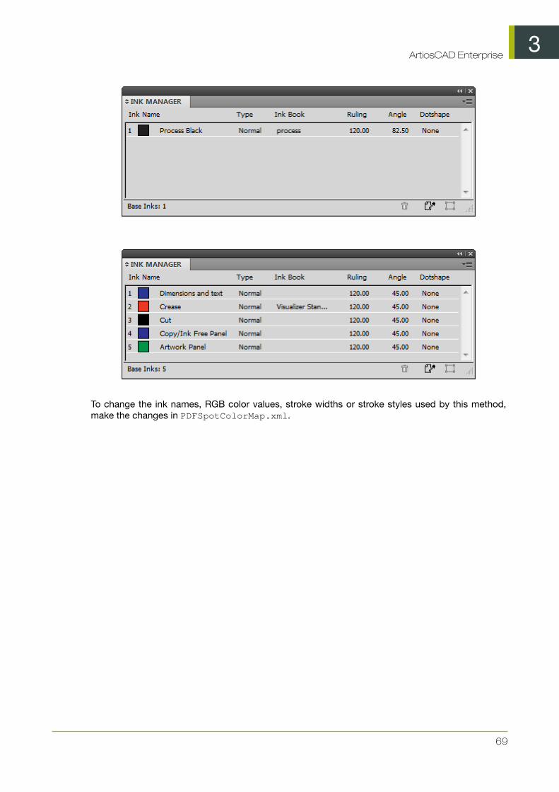
3ArtiosCAD Enterprise
69
To change the ink names, RGB color values, stroke widths or stroke styles used by this method,make the changes in PDFSpotColorMap.xml.
4ArtiosCAD Enterprise
70
4. Installing Esko ArtiosCAD
Introduction
There are three types of installations: Typical, Advanced, and Silent. Each can be used as a newinstallation or as an upgrade from a previous version of Esko ArtiosCAD.
Typical is for most situations. It uses the same machine for Esko ArtiosCAD Defaults, Licensing,and the database. A Typical installation can be Standalone (meaning it relies on no other computersfor Esko ArtiosCAD and DataCenter Admin to work), a Server (meaning it shares its configurationinformation with other Esko ArtiosCAD machines on the network) or a Standard Client (meaning itgets its Esko ArtiosCAD configuration information from one other Esko ArtiosCAD system on thenetwork). It does not install the legacy LASERPOINT IQ and The Designer WorkBench Standardscatalogs. You may also choose the type of database to be used with Esko ArtiosCAD. Microsoft®SQL Server 2005 Express Edition, Oracle®, or Microsoft SQL Server may be used as the databaseengine. However, Esko does not support the installation, operation, or maintenance of Oracle or afull version of Microsoft SQL Server.
Advanced is used for more complex customized installations. Different machines can be specifiedfor Esko ArtiosCAD Defaults, Licensing (if applicable), and the database.
Additionally, in an advanced installation, you can specify to install Esko ArtiosCAD so that itis non-version-specific, meaning that the icons and directories are named Esko ArtiosCAD, notEsko ArtiosCAD12 Enterpriseen, for example, and future upgrades would overwrite the existinginstallation.
A Silent installation presents no dialog boxes, and all options must be specified on the commandline. This is meant for use only in large corporate WAN environments where one central administratorinstalls Esko ArtiosCAD on other computers to which the administrator has remote command access.The silent installation program must be run on the computer on which Esko ArtiosCAD will beused. The silent installation program may not be run on one machine resulting in Esko ArtiosCADbeing installed on another machine. Contact Support for more information on performing a Silentinstallation.
Note: Keep the original Esko ArtiosCAD media in a safe, easily-accessible place in case you needto modify or repair the installation. You must use the same media or network location to repair ormodify Esko ArtiosCAD as when you first installed the software.
The table below summarizes the options available in the three installations for conventional versions.Enterprise versions use WebCenter servers for licensing and database functions.
Choice TypicalInstallation
AdvancedInstallation
SilentInstallation
Ability to use choose database engine
(Configuration batch file must be runmanually after Esko ArtiosCAD installation
• • •
4ArtiosCAD Enterprise
71
Choice TypicalInstallation
AdvancedInstallation
SilentInstallation
finishes for Oracle and Microsoft SQLServer)
Ability to use same computer for EskoArtiosCAD Defaults server, License server,and database server
• • •
Ability to specify different computers forEsko ArtiosCAD Defaults, Licensing, anddatabase
• •
Ability to choose Esko ArtiosCADinstallation directory
• • •
Esko ArtiosCAD program executableand Esko ArtiosCAD Standards Catalogautomatically selected for loading
•
Selectively load all components • • •
Choose to load The Designer WorkBenchand LASERPOINT Standards cata-logs
• • •
Automatically keep previous versions (useversion-specificness)
•
Choose to keep previous versions oroverwrite them
• •
Ability to choose default location of EskoArtiosCAD users’ design files
• •
Performing a Typical installation
Note: If you receive a message about overwriting read-only files, answer yes to overwrite them.Also, if you receive a message about a control failing to register, proceed normally and reboot whenthe installation finishes.
To perform a typical Esko ArtiosCAD installation, do the following:
1. Log on as Administrator, or as a user with administrative privileges.2. Ensure there is at least 5 GB of free space on the hard drive or partition where Esko ArtiosCAD
will be loaded and 500 MB of free space on the operating system hard drive or partition.3. Put the Esko ArtiosCAD media into the computer’s media drive. It should automatically launch
the Setup program. If your drive is set to not AutoPlay, start Windows Explorer and double-clicksetup.exe in the root directory of the media.
4. The Esko ArtiosCAD Setup dialog box appears. Click the button next to Install Esko ArtiosCAD<version number> to start installing Esko ArtiosCAD.

4ArtiosCAD Enterprise
72
5. Depending on your system configuration prior to loading Esko ArtiosCAD, the Microsoft DataAccess Components and MSXML 6 may be copied to your system. Two status boxes will appear:one showing the copying of the files, and perhaps one showing the configuration of Control Panel.If the system prompts you to reboot, do so; the installation program will resume automaticallywhen you log in after the system comes up again. Do not postpone rebooting if the systemrequests it.
6. Click Next in the Welcome to the InstallShield Wizard for Esko ArtiosCADX.xx dialog box.7. Read the Software License Agreement in its entirety and choose I accept the terms of the license
agreement if you accept all the terms of the License Agreement. Click Next.8. If upgrading from a previous version of Esko ArtiosCAD, choose to copy the Defaults from the
last version loaded, or choose to use the default configuration which will install a completelyunmodified set of Defaults. You should copy the previous configuration if you customized EskoArtiosCAD in any way, such as adding Output devices and making your own Reports. Click Next.If there is no prior version of Esko ArtiosCAD on this machine, you are not prompted to choosean upgrade version.
9. Choose a Typical installation and click Next. If you are upgrading systems with distributed servers,you must do an Advanced installation.
10.In the Feature Selection dialog box, choose the features to install on the current machine. Foreach feature, click the icon in the drop-down list box next to it and choose the appropriate choice.Do not click Next when done, but rather proceed to the next numbered step.
Esko ArtiosCAD Configuration. Click the plus sign (+) next to this entry to open it. Esko ArtiosCADLicensing, Esko ArtiosCAD Defaults, and Esko ArtiosCAD Database can each be installedin any combination on a machine. For Typical and all Standalone installations, leave them allselected.
Esko ArtiosCAD Programs. Esko ArtiosCAD Programs are the program files needed to run EskoArtiosCAD. You must install these if you want to run Esko ArtiosCAD on the current machine.Not installing these would create a server-only installation provided the servers were selected forinstallation. You must leave this choice selected to install Esko ArtiosCAD itself.
Contained within the Esko ArtiosCAD Programs group are optional components of EskoArtiosCAD that require purchasing licenses for the corresponding modules: PDF Import/Export,3D Connection and Filters, and SolidWorks Import/Export. Refer to the printed licensereport that came with the media to determine which components to select. Installing softwarecomponents without having the corresponding licenses wastes disc space. Not installing thesoftware components but having the licenses for them results in features that do not functionwithin Esko ArtiosCAD.
Esko Configuration Manager collects data from systems running the Esko Station InformationService and sends the collected data to Esko automatically for use by Support personnel. Itsends information only if you configure it to do so and leave it enabled. It is a great aidto Support personnel as they will have required information about your hardware and licensesavailable should you need to call for assistance. Only one system per site should have theEsko Configuration Manager installed. Refer to the separate document Scope ConfigurationManager 1.0 Software Installation and Configuration Manual on the Esko ArtiosCAD media(SCM_nn_SICFM.PDF in the User Docs folder) for more information.
Laserpoint Standards Catalog is a legacy Standards catalog for single designs. Only install thisif there are LASERPOINT or LASERPOINT IQ standards you want to run.
Designer WorkBench Standards Catalog is a legacy Standards catalog for single designs. Onlyinstall this if you want to run standards from The Designer WorkBench.

4ArtiosCAD Enterprise
73
11.While still in the Feature Selection dialog box, with one of the components to be installed selected,review the folder in which Esko ArtiosCAD will be installed, and click Change if desired. In theresulting Change Current Destination Folder dialog box, change the drive if desired, and click OKto return to the Feature Selection dialog box. Esko ArtiosCAD should always be installed to the\Esko\Artios folder on a local drive. Click Next.
12.If this is a new installation, choose the database program for Esko ArtiosCAD to use. The defaultand recommended choice is SQL Server 2005 Express Edition, a free desktop database fromMicrosoft. Choosing Microsoft SQL Server or Oracle is appropriate for workgroup or enterpriseuse where those databases are already in use. If this is an upgrade, you may not be asked tochoose a database type depending on the one already in use.
If this is an upgrade, and you want to switch from using MSDE to using SQL Server 2005 ExpressEdition
Note: If you choose Microsoft SQL Server or Oracle, configuration scripts and a batch file for thosedatabases will be placed in the \Esko\Artios\DataCenter directory. The database administratorMUST run the appropriate batch file before using Esko ArtiosCAD or DataCenter Admin. Other post-installation tasks must be performed as well.
1. Choose the System type. Standalone shares nothing - it is entirely self-contained. A Server sharesits Esko ArtiosCAD configuration with other machines on the network. A Standard Client getsits Esko ArtiosCAD configuration from another system on the network; there must be a Serverloaded and running before loading any Standard Clients.
At this point, the Typical installation branches into two parts. If you chose Standalone or Server,proceed as directed below. If you chose Standard client, proceed to the Typical Standard Clientinstallation section.
Typical Standalone or Server installation
1. Having chosen Standalone or Server as the system type, click Next.2. Review the summary of installation settings. If they are correct, click Install to start installing files.
If not, click Back to go back and change settings.3. If this is a new installation, the Esko Station Information Service will be installed automatically.
This service collects information about your hardware, software, and Esko licenses. If the EskoScope Configuration Manager service is installed on a machine on your network, it will forwardthe information collected to Esko for use by Support personnel if you configure it to do so. Severaldialog boxes will appear displaying information; you do not need to click anything as they willautomatically continue.
4. A progress indicator shows the status of the copying process. If this system is a Server and thisis a new installation of Esko ArtiosCAD, click OK when told that the Artios directory has beenshared.
5. The Esko ArtiosCAD Setup program might prompt for a system reboot. Click Yes to reboot thesystem.
Once the system comes back up, Esko ArtiosCAD and DataCenter Admin will be fully functional6. If you installed a non-English version of Esko ArtiosCAD, run \Esko\Artios\DataCenter\program
\<language>\dbtranslate.exe to make DataCenter compatible with your language.7. Activate the license using the Activate Local Licenses application in the ArtiosCAD folder for a
local license, or for a network license, by using the Activate Licenses application in the System

4ArtiosCAD Enterprise
74
Controller subfolder of the Esko folder of the Start menu. For more more information on licensemanagement, refer to the documents available for ArtiosCAD at http://help.esko.com.
8. You are now ready to configure Esko ArtiosCAD.
Typical Standard Client Installation
Note: If you are upgrading and your Esko ArtiosCAD installation is set up so that different machinesact as different servers, Typical Standard Client installations will not work, as they require a unifiedserver. If your system uses multiple servers, you must perform an Advanced Client/Server installation.
1. Before doing a Standard Client installation, make sure there is a Server installation on anothermachine which is running and on the network, and note the name of the Server machine. Alsomake sure there is at least 5 GB of free space on the hard drive or partition where Esko ArtiosCADwill be loaded and 500 MB free on the system hard drive or partition.
2. Having chosen the Standard Client system type, enter the name of the server in the EskoArtiosCAD Server: field of the System Type dialog box. Click Next after entering the name.
3. Review the installation settings listed in the summary list. If they are correct, click Install to startinstalling files. If not, click Back to go back and change settings.
4. Depending on your system configuration prior to loading Esko ArtiosCAD, the Microsoft DataAccess Components may be copied to your system. Two status boxes may or may not appear:one showing the copying of the files, and perhaps one showing the configuration of Control Panel.
5. A progress indicator shows the status of the copying process.6. The Esko ArtiosCAD Setup program might prompt for a system reboot. Click Yes to reboot the
system.7. Once the system comes back up, Esko ArtiosCAD and DataCenter Admin will be fully functional.
This Esko ArtiosCAD system will use the same configuration files as those on the Server, soconfiguration of this system is unnecessary.
If you installed a non-English version of Esko ArtiosCAD, run \Esko\Artios\DataCenter\program\<language>\dbtranslate.exe to make DataCenter compatible with your language.
Performing an Advanced installation
To perform an Advanced installation of ArtiosCAD, do the following:
1. Log on as Administrator, or as a user with administrative privileges.2. Ensure there is at least 5 GB of free space on the hard drive or partition where ArtiosCAD will be
loaded and 500 MB of free space on the operating system hard drive or partition.3. Put the ArtiosCAD media into the computer’s media drive. The setup program should start
automatically. If it does not, start Windows Explorer and double-click setup.exe in the rootdirectory of the media.
4. The ArtiosCAD Setup dialog box appears. Click the button next to Install ArtiosCAD <versionnumber> to start installing ArtiosCAD.
5. Depending on your system configuration prior to loading ArtiosCAD, the Microsoft Data AccessComponents and MSXML 6 may be copied to your system. Two status boxes will appear: oneshowing the copying of the files, and perhaps one showing the configuration of Control Panel. If

4ArtiosCAD Enterprise
75
the system prompts you to reboot, do so; the installation program will resume automatically whenyou log in after the system comes up again. Do not postpone rebooting if the system requests it.
6. Click Next in the Welcome dialog box.7. Read the License Agreement in its entirety and choose I accept the terms of the license
agreement if you accept all the terms of the License Agreement. Click Next.8. If upgrading from a previous version of ArtiosCAD, choose to copy the defaults from the
last version loaded, or choose to use the default configuration which will install a completelyunmodified set of Defaults. You should copy the previous configuration if you customizedArtiosCAD in any way, such as adding Output devices and making your own Reports. Click Next.If there is no prior version of ArtiosCAD on this machine, you are not prompted to choose anupgrade version.
9. Choose Advanced in the Setup Type dialog box and click Next.10.In the Feature Selection dialog box, choose the features to install on the current machine.For each
feature, click the icon in the drop-down list box next to it and choose the appropriate choice. Donot click Next when done, but rather proceed to the next numbered step.
ArtiosCAD Configuration. Click the plus sign (+) next to this entry to open it. ArtiosCAD Licensing,ArtiosCAD Defaults, and ArtiosCAD Database Server can each be installed in any combinationon a machine.
ArtiosCAD Programs are the program files needed to run ArtiosCAD. You must install these ifyou want to run ArtiosCAD on the current machine. Not installing these would create a server-only installation provided the servers were selected for installation.
Contained within the ArtiosCAD Programs group are optional components of ArtiosCAD thatrequire purchasing licenses for the corresponding modules: PDF Import/Export and 3D Importer.Refer to the printed license report that came with the media to determine which componentsto select. Installing software components without having the corresponding licenses will simplywaste disc space. Not installing the software components but having the licenses for them willlead to features that do not function within ArtiosCAD.
Esko Configuration Manager collects data from systems running the Esko Station InformationService, and if you configure it to do so, sends the collected data to Esko automatically for useby Support personnel. It is a great aid to Support personnel as they will have required informationabout your hardware and licenses available should you need to call for assistance. Only onesystem per site should have the Esko Configuration Manager installed. Refer to the separatedocument Scope Configuration Manager 1.0 Software Installation and Configuration Manual(scm_10_sicfm.pdf) for more information.
Laserpoint Standards Catalog is a legacy Standards catalog for single designs. Only install thisif there are LASERPOINT or LASERPOINT IQ standards you want to run.
Designer WorkBench Standards Catalog is a legacy Standards catalog for single designs. Onlyinstall this if you want to run standards from The Designer WorkBench.
11.While still in the Feature Selection dialog box, review the directory to which ArtiosCAD will beinstalled, and click Change if desired. In the resulting Change Current Destination Folder dialogbox, navigate to the desired directory, select it, and click OK to return to the Feature Selectiondialog box. Click Next.
12.In the Database Program Selection dialog box, the database selection defaults to SQL Server2005 Express Edition, the free desktop database from Microsoft. Microsoft SQL Server and Oracleboth work with ArtiosCAD, but it is your responsibility to purchase, install, configure, and maintainthem. Additionally, if you have MSDE on your system for use with another program, you maychoose to use it, but if you do not already have it loaded, it is not presented as a choice.
4ArtiosCAD Enterprise
76
Note: If you choose Microsoft SQL Server or Oracle, configuration scripts and a batch filefor those databases will be placed in the \Esko\Artios\DataCenter directory. The databaseadministrator MUST run the appropriate batch file before using ArtiosCAD or DataCenter Admin.Other post-installation tasks must be performed as well.
13.In the Advanced Options dialog box, Keep Previous Versions is the default for previous versionhandling. It means that ArtiosCAD is installed using a version-specific folder and icon which matchthe version and language of the installation, and all previous versions of ArtiosCAD are kept.To change this setting, click Change. In the Previous Version Handling dialog box, Overwriteprevious versions simply uses ArtiosCAD as the icon name and ArtiosCAD as the directory with noversion number. It overwrites the prior version of ArtiosCAD if this is an upgrade and the previousversion was installed to a non-version-specific directory. Once you have chosen the option touse, click OK to return to the Advanced Options dialog box.
If you are using SQL Server 2005 Express Edition or Microsoft SQL Server 2005 as thedatabase, you have the choice of database authentication methods. SQL Server Authenticationrequires each user to have a login created within the database; by default, ArtiosCAD usesone database user (programmer) for all ArtiosCAD users. However, your company may havedifferent requirements. Windows Authentication passes operating system login credentials tothe database. You should use Windows Authentication only if you have a dedicated databaseadministrator who can perform user maintenance tasks.
Click Next.14.In the System Type dialog box, choose the type of system this will be, mindful of the modules
chosen for installation in step 10. For example, if you elected not to install ArtiosCAD Programs,this system cannot be a Standalone system, but it can be a Server or Advanced Client/Server.
If this system is to be a Standard Client, enter the name of the ArtiosCAD Server in the appropriatefield.
If you intend this machine to be a server only, select Advanced Client/Server, and enter thesystem name in the fields that this machine will serve. If it will only be one kind of server, enter thesystem name in the appropriate field, and enter the names of the other servers in their appropriatefields.
If you choose Advanced Client/Server, enter the names of the systems acting as the Defaultsserver, License Server, and Database Server. If the database is not Microsoft Access, the DatabaseServer field is unavailable; the database server must be configured manually via the ArtiosCADentry in the ODBC control panel. You can enter the same system name in all three fields, or youcan specify a different system in each field. If you enter remote system names, and those remotesystems do not have ArtiosCAD loaded on them, you will have to manually enter the exact pathto the applicable resources. ArtiosCAD must be loaded on the server you indicated on theseremote systems for ArtiosCAD to work on the current system! It does not have to be loadedat the time of the current system upgrade, but should be loaded soon afterward.
You can also specify the name of the current system if you want it to act as its own server forany of the functions listed.
Click Next when done choosing the system type.15.If Setup cannot find the appropriate service files for any of the three servers entered in the previous
step, for example if you have not loaded ArtiosCAD on those machines yet, it will ask for theUNC locator for the service. The instructions in the dialog box will provide an example to use for
4ArtiosCAD Enterprise
77
entering the location, but make sure the data you enter is correct for your configuration. ClickNext when you have entered the full location for the service.
16.The default location for the storage of user files is shown in the User Files Folder dialog box. Tochange it, click Change; to accept it, click Next. If you change the location to another system,use a UNC locator (e.g. \\system2\designs) instead of a mapped drive letter.
17.Review the settings listed in the Ready to Install the Program dialog box. If they are correct, clickInstall to start copying files. If not, click Back to go back and change settings.
18.If this is a new installation, the Esko Station Information Service will be installed automatically.This service collects information about your hardware, software, and Esko licenses. If the EskoConfiguration Manager service is installed on a machine on your network, it will forward theinformation collected to Esko for use by Support personnel if you configure it to do so. Severaldialog boxes will appear displaying information; you do not need to click anything as they willautomatically continue.
19.A progress indicator will show the status of the copying process. Click OK if told that the Artiosdirectory has been shared.
20.The ArtiosCAD Setup program might prompt for a system reboot. Click Finish to reboot thesystem.
21.Activate the license using the Activate Local Licenses application in the ArtiosCAD folder for alocal license, or for a network license, by using the Activate Licenses application in the SystemController subfolder of the Esko folder of the Start menu. For more more information on licensemanagement, refer to the documents available for ArtiosCAD at http://help.esko.com.
22.Reboot the system if you are prompted to do so. Once the system comes back up, ArtiosCADand DataCenter Admin will be fully functional if the system is using a MSDE or SQL Server 2005Express Edition database.
If you installed a non-English version of ArtiosCAD, run \Esko\Artios\DataCenter\program\<language>\dbtranslate.exe to make DataCenter compatible with your language.
If the system does not use MSDE or SQL Server 2005 Express Edition as the database engine, seeUsing other databases with Esko ArtiosCAD.
Note: If you choose to distribute tasks among remote servers, you must load ArtiosCADon each of those servers as an Advanced installation, specifying those server names in theappropriate fields of the Advanced Client/Server choice in the System Type dialog box.
Using other databases with Esko ArtiosCAD
If you chose Microsoft SQL Server or Oracle in the Database Program Selection dialog box, yourdatabase administrator must configure the database to work with Esko ArtiosCAD. See Running theEsko ArtiosCAD database configuration batch file for Microsoft SQL Server 2005 or 2000 or UsingOracle for Oracle.
Other database notes
To change the database engine used with Esko ArtiosCAD, delete the ArtiosCAD data source fromthe System DSN tab of the ODBC Data Sources control panel and reinstall Esko ArtiosCAD.

4ArtiosCAD Enterprise
78
Oracle databases should either have autoexpand set for the tablespace or should have a very largemaximum extent set.
Do not change the database password in a vendor-supplied utility. Rather, change it in DataCenterAdmin by using the File > Change Database Password command.
Advanced Upgrading of Esko ArtiosCAD on a server
Notes and warnings before you begin
Because the upgrade process is highly configurable, there are many situations which must beconsidered before beginning the upgrade process.
If you specified remote servers for ArtiosCAD Defaults, ArtiosCAD Licensing, or ArtiosCAD Database,you must load Esko ArtiosCAD on those servers as Advanced installations, specifying their systemnames in the appropriate fields in the System Type dialog box on each system.
If you have a remote License server, make sure your licensing information is loaded on that server.
If you are upgrading the current server and specifying a remote Esko ArtiosCAD Defaults server, copythe contents of the current system’s ServerLib to that remote system’s ServerLib directory.
Upgrading other databases with Esko ArtiosCAD
If you use Oracle or Microsoft SQL Server 2000 as the database engine, you must run theconfiguration batch file after Esko ArtiosCAD finishes loading and the system has rebooted (ifapplicable). See the appropriate sections further in the manual about running the batch file for moreinformation.
Other database notes
To change the database engine used with Esko ArtiosCAD, delete the ArtiosCAD data source on theSystem DSN tab from the ODBC control panel and reinstall Esko ArtiosCAD.
Oracle databases should either have autoexpand set for the tablespace or should have a very largemaximum extent set.
Do not change the database password in a vendor-supplied utility. Rather, change it in DataCenterAdmin by using the File > Change Database Password command.
4ArtiosCAD Enterprise
79
Changing to SQL Server 2005 Express Edition on thedatabase server
SQL Server 2005 Express Edition is a replacement for Microsoft Access and MSDE which Eskobelieves offers greater stability and better performance for Esko ArtiosCAD.
If your system currently uses Microsoft Access as the database engine, you must upgrade it to SQLServer 2005 Express Edition. If your system currently uses MSDE, you may continue to use it, butSQL Server 2005 Express Edition offers better performance than MSDE.
If you choose to change to SQL Server 2005 Express Edition, you should export non-design-baseddatabase information from the old database before starting to load Esko ArtiosCAD. The migrationto SQL Server 2005 Express Edition should be error-free, but if there are problems, you can importthis data into a blank database and then do an AutoLoad to create a new database.
Exporting database information from the old database
To export non-design-based data from the existing database, do the following:
1. Ensure that any programs using the database are not running.2. Log on to the database server as Administrator or as a member of the Administrators group.3. Click Start > Programs > ArtiosCAD > Migration Tools > ArtiosCAD Database Export.4. Enter admin as the username with no password, and click OK.5. The utility will appear similar to the picture shown below.

4ArtiosCAD Enterprise
80
6. Enter a sensible file name and location in the Migration Filename and Path: group.7. Select all the available tables.8. Click Export. The progress bar indicates the progress of the export.9. When the export is done, click Exit. If the migration to SQL Server 2005 Express Edition is error-
free, you can delete the exported file after the migration if desired.
Loading the upgrade
When you install Esko ArtiosCAD as an upgrade and and have been using Microsoft Access or MSDEas the database engine, choose SQL Server 2005 Express Edition as the database type, a checkboxappears asking if you want to migrate prior database data to SQL Server 2005 Express Edition if thissystem is the database server.

4ArtiosCAD Enterprise
81
If you choose SQL Server 2005 Express Edition as the database program and this system is thedatabase server, the following actions happen:
• A database schema is built or updated as appropriate.• The existing ArtiosCAD ODBC datasource is renamed to ArtiosCAD_Access or ArtiosCAD_MSDE
as appropriate.• Empty command prompt windows appear.• The ArtiosCAD ODBC data source changes to reference the new SQL Server 2005 Express Edition
database.• A service called SQL Server (ARTIOSCADEXP2005) is created and started.
If this system is not the database server, the ArtiosCAD ODBC datasource changes to reference theSQL Server 2005 Express Edition database.
If you choose to migrate the data, the setup program tries to export the data from the old database.If the export is successful, the data is migrated to the SQL Server 2005 Express Edition database.
If you do not choose to migrate the data, a blank SQL Server 2005 Express Edition database iscreated and you have to manually export the data from the old database and manually import thedata into SQL Server 2005 Express Edition.
Automatic migration
If you choose to have the setup program migrate the data, a series of empty command promptwindows appears during the installation while the migration tasks are executing. Their duration isdirectly proportional to the size of the old database.
If there are errors during the migration process, you must manually migrate the data as instructedin the next section.
Signs of a successful migration are:
• Data appearing in the design browsers in Esko ArtiosCAD, and also in DataCenter Admin,provided that the Esko ArtiosCAD System DSN uses a Microsoft SQL Server driver.
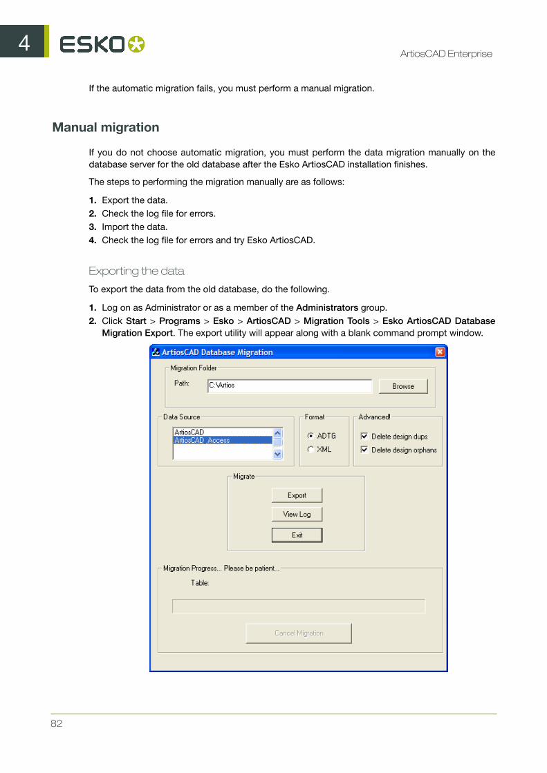
4ArtiosCAD Enterprise
82
If the automatic migration fails, you must perform a manual migration.
Manual migration
If you do not choose automatic migration, you must perform the data migration manually on thedatabase server for the old database after the Esko ArtiosCAD installation finishes.
The steps to performing the migration manually are as follows:
1. Export the data.2. Check the log file for errors.3. Import the data.4. Check the log file for errors and try Esko ArtiosCAD.
Exporting the data
To export the data from the old database, do the following.
1. Log on as Administrator or as a member of the Administrators group.2. Click Start > Programs > Esko > ArtiosCAD > Migration Tools > Esko ArtiosCAD Database
Migration Export. The export utility will appear along with a blank command prompt window.

4ArtiosCAD Enterprise
83
The Migration Folder group shows the folder that stores the files created by the export utility. Theexport files require the same amount of hard drive space as the Microsoft Access database file, somake sure to choose a location with enough free space. Click Browse to select a new location.
The Data Source group lists the available data sources. Make sure to select the ArtiosCAD_Accessor ArtiosCAD_MSDE as the data source for this migration.
The Format group selects the format of the migration files. ADTG is the default; if it errors, try XML.
In the Advanced group, Delete design dups deletes duplicate design records in the database;preserving the newest record and discarding older duplicates. Delete orphans deletes table entriesthat no longer have corresponding design records on the hard drive. Both options are enabled bydefault.
The Migrate group contains the actual commands. Export exports the data from the selected datasource in the format selected to the migration folder. View Log opens the log file of the export. Itis stored in the system temporary directory as ACadFullDbMigrationExportLog.txt. Exit exits theprogram.
The Migration Process group contains the progress bar showing the table being exported. Thelength of time required to export the data is directly proportional to the size of the database. CancelMigration cancels the migration. Do not use the migration files created by a cancelled migration.
1. Set the migration folder and format as desired, select the ArtiosCAD_Access orArtiosCAD_MSDE data source, and click Export. During the export, all controls in the dialog boxare unavailable except for Cancel Migration.

4ArtiosCAD Enterprise
84
2. There should be no errors. If an error appears, delete all the ADTG files created by this migrationand try using XML for the migration format. If there are no errors, the next step is to check thelog file.
Checking the log file for export errors
1. Even if no errors appeared during export, click View Log to view the log file. Information, warnings,and errors are logged. Check the log file for warnings and errors. Warnings related to tables notexisting are usually caused by database schema differences among Esko ArtiosCAD versions;these can be safely ignored. Only errors warrant concern. A sample log file is shown below; yoursmight vary.
Table: Sample ACadDBFullMigrationExportLog.txt
Information: [Exporting table] CODE_TYPE Information: [Exporting table] IQ_DEFAULTS Information: [Exporting table] CODE Information: [Exporting table] HIERARCHICAL_STYLES Information: [Exporting table] COMPANY Information: [Exporting table] PERSON Information: [Exporting table] FLUTE Information: [Exporting table] BOARD_FOLDER
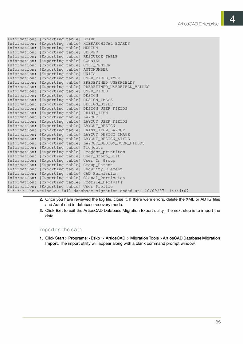
4ArtiosCAD Enterprise
85
Information: [Exporting table] BOARD Information: [Exporting table] HIERARCHICAL_BOARDS Information: [Exporting table] MEDIUM Information: [Exporting table] SERVER Information: [Exporting table] RESOURCE_TABLE Information: [Exporting table] COUNTER Information: [Exporting table] COST_CENTER Information: [Exporting table] AUTONUMBER Information: [Exporting table] UNITS Information: [Exporting table] USER_FIELD_TYPE Information: [Exporting table] PREDEFINED_USERFIELDS Information: [Exporting table] PREDEFINED_USERFIELD_VALUES Information: [Exporting table] USER_FIELD Information: [Exporting table] DESIGN Information: [Exporting table] DESIGN_IMAGE Information: [Exporting table] DESIGN_STYLE Information: [Exporting table] DESIGN_USER_FIELDS Information: [Exporting table] PRINT_ITEM Information: [Exporting table] LAYOUT Information: [Exporting table] LAYOUT_USER_FIELDS Information: [Exporting table] LAYOUT_DESIGN Information: [Exporting table] PRINT_ITEM_LAYOUT Information: [Exporting table] LAYOUT_DESIGN_IMAGE Information: [Exporting table] LAYOUT_DESIGN_STYLE Information: [Exporting table] LAYOUT_DESIGN_USER_FIELDS Information: [Exporting table] Projects Information: [Exporting table] Project_printitem Information: [Exporting table] User_Group_List Information: [Exporting table] User_In_Group Information: [Exporting table] Group_Parent Information: [Exporting table] Security_Element Information: [Exporting table] CAD_Permission Information: [Exporting table] Global_Permission Information: [Exporting table] Profile_Defaults Information: [Exporting table] User_Profile ******* The ArtiosCAD full database migration ended at: 10/09/07, 14:44:07
2. Once you have reviewed the log file, close it. If there were errors, delete the XML or ADTG filesand AutoLoad in database recovery mode.
3. Click Exit to exit the ArtiosCAD Database Migration Export utility. The next step is to import thedata.
Importing the data
1. Click Start > Programs > Esko > ArtiosCAD > Migration Tools > ArtiosCAD Database MigrationImport. The import utility will appear along with a blank command prompt window.
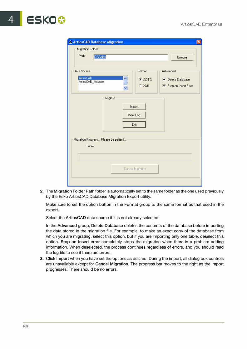
4ArtiosCAD Enterprise
86
2. The Migration Folder Path folder is automatically set to the same folder as the one used previouslyby the Esko ArtiosCAD Database Migration Export utility.
Make sure to set the option button in the Format group to the same format as that used in theexport.
Select the ArtiosCAD data source if it is not already selected.
In the Advanced group, Delete Database deletes the contents of the database before importingthe data stored in the migration file. For example, to make an exact copy of the database fromwhich you are migrating, select this option, but if you are importing only one table, deselect thisoption. Stop on Insert error completely stops the migration when there is a problem addinginformation. When deselected, the process continues regardless of errors, and you should readthe log file to see if there are errors.
3. Click Import when you have set the options as desired. During the import, all dialog box controlsare unavailable except for Cancel Migration. The progress bar moves to the right as the importprogresses. There should be no errors.

4ArtiosCAD Enterprise
87
Checking the log file for import errors
1. Even if there are no errors, click View Log when the import is done to review the log file for errors.Information, warnings, and errors are logged. Check the log file for warnings and errors. A samplelog file is shown below; yours might vary.
Table: Sample ACadDBFullMigrationImportLog.txt
******* The ArtiosCAD full database migration began at: 10/09/07, 14:52:17 Information: Deleting data from all tables Information: [Importing data] code_type [C:\Artios\code_type.adtg] Information: [Importing data] iq_defaults [C:\Artios\iq_defaults.adtg] Information: [Importing data] code [C:\Artios\code.adtg] Information: [Importing data] hierarchical_styles [C:\Artios\hierarchical_styles.adtg] Information: [Importing data] company [C:\Artios\company.adtg] Information: [Importing data] person [C:\Artios\person.adtg] Information: [Importing data] flute [C:\Artios\flute.adtg] Information: [Importing data] board_folder [C:\Artios\board_folder.adtg] Information: [Importing data] board [C:\Artios\board.adtg] ...Information: [Importing data] cad_permission [C:\Artios\cad_permission.adtg] Information: [Importing data] global_permission [C:\Artios\global_permission.adtg] Information: [Importing data] profile_defaults [C:\Artios\profile_defaults.adtg]
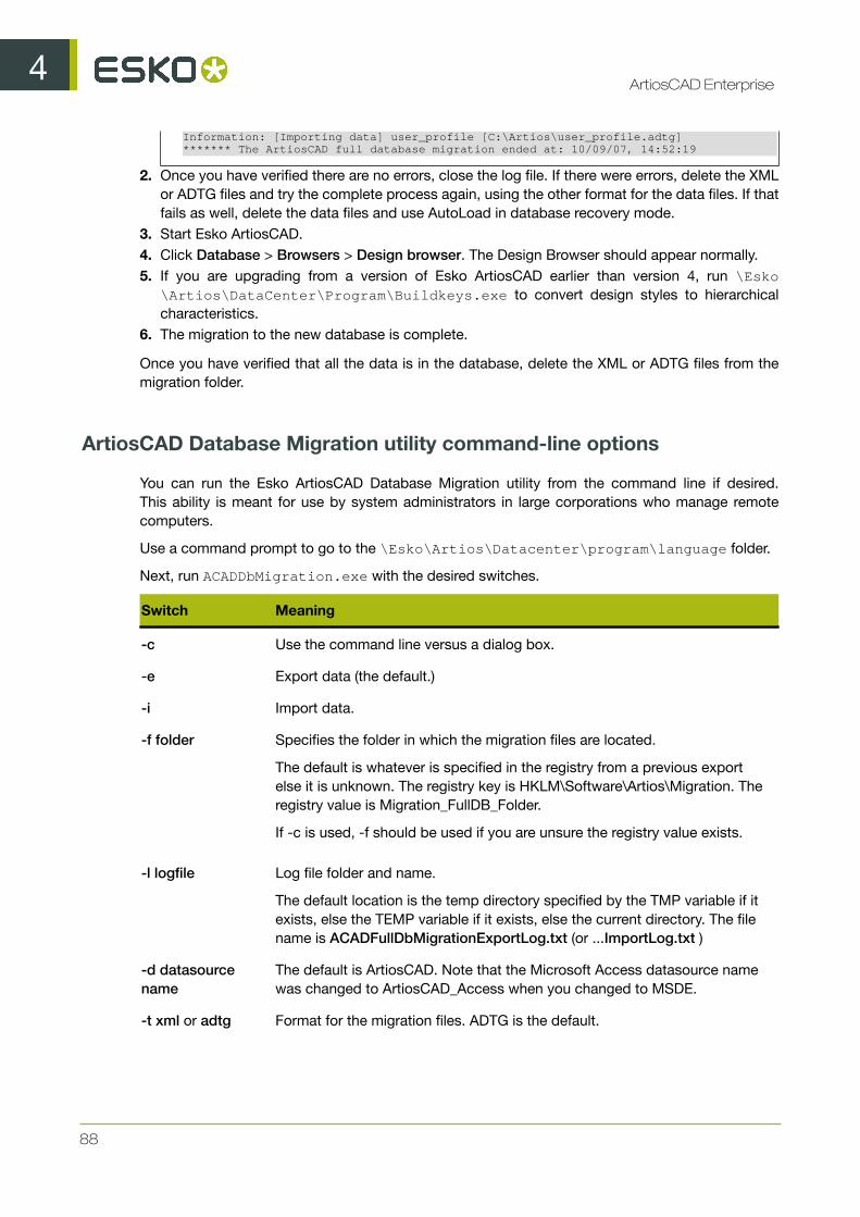
4ArtiosCAD Enterprise
88
Information: [Importing data] user_profile [C:\Artios\user_profile.adtg] ******* The ArtiosCAD full database migration ended at: 10/09/07, 14:52:19
2. Once you have verified there are no errors, close the log file. If there were errors, delete the XMLor ADTG files and try the complete process again, using the other format for the data files. If thatfails as well, delete the data files and use AutoLoad in database recovery mode.
3. Start Esko ArtiosCAD.4. Click Database > Browsers > Design browser. The Design Browser should appear normally.5. If you are upgrading from a version of Esko ArtiosCAD earlier than version 4, run \Esko
\Artios\DataCenter\Program\Buildkeys.exe to convert design styles to hierarchicalcharacteristics.
6. The migration to the new database is complete.
Once you have verified that all the data is in the database, delete the XML or ADTG files from themigration folder.
ArtiosCAD Database Migration utility command-line options
You can run the Esko ArtiosCAD Database Migration utility from the command line if desired.This ability is meant for use by system administrators in large corporations who manage remotecomputers.
Use a command prompt to go to the \Esko\Artios\Datacenter\program\language folder.
Next, run ACADDbMigration.exe with the desired switches.
Switch Meaning
-c Use the command line versus a dialog box.
-e Export data (the default.)
-i Import data.
-f folder Specifies the folder in which the migration files are located.
The default is whatever is specified in the registry from a previous exportelse it is unknown. The registry key is HKLM\Software\Artios\Migration. Theregistry value is Migration_FullDB_Folder.
If -c is used, -f should be used if you are unsure the registry value exists.
-l logfile Log file folder and name.
The default location is the temp directory specified by the TMP variable if itexists, else the TEMP variable if it exists, else the current directory. The filename is ACADFullDbMigrationExportLog.txt (or ...ImportLog.txt )
-d datasourcename
The default is ArtiosCAD. Note that the Microsoft Access datasource namewas changed to ArtiosCAD_Access when you changed to MSDE.
-t xml or adtg Format for the migration files. ADTG is the default.

4ArtiosCAD Enterprise
89
Changing to SQL Server 2005 Express Edition on clientsystems
If you change your database server to SQL Server 2005 Express Edition, you must also load theupgrade on all client systems to configure them to use the new server software. No database softwareis loaded on clients.

5ArtiosCAD Enterprise
90
5. Peripherals
Esko ArtiosCAD can output to devices that use a standard Microsoft Windows driver and also todevices simply connected to a port on an Esko ArtiosCAD computer. Devices that do not use aWindows driver use Output Destinations which are configured in the Output Destinations dialog boxin Shared Defaults.
Note: This documentation refers to configuring devices in Shared Defaults for all users to access.Configuring a device for use on a single machine in User Defaults follows the same procedure,substituting User Defaults for Shared Defaults.
Installing a Windows printer
Esko ArtiosCAD prints by default to the default Windows printer on the system on which it is running.
For information on installing a printer in the Windows family of operating systems, read the Settingup a Printer topic in the How to…Set Up Hardware section of Help.
If this is the first printer installed on the system, it is automatically designated as the system defaultprinter. The Print command and the Plot to Printer output ( File > Outputs > Artios > Printer Output> Plot to Printer) will use it by default.
To add an Output for a newly-installed printer if it is not the system default printer, do the following:
1. Start Esko ArtiosCAD2. Open Defaults by clicking Options > Defaults.3. In the Shared Defaults pane, scroll down to Outputs.4. Right-click Outputs, click New from the context menu, and then click Data.
5. Enter a name for the Output such as the name of the printer; for example, HP DeskJet 560C.6. Double-click the new Output just created to open its Property page.7. The Device tab will be selected automatically. Leave the Output type set as Plot and change the
Scale to To fit one page.

5ArtiosCAD Enterprise
91
8. Click the Device tab. If a dialog box appears with the message System printer information couldnot be read, click OK.
9. Under Windows Driver, click the drop-down list box arrow and select the newly-created printer.
10.Click OK, then File, then Save to accept the printer and save the defaults.11.Click Yes when asked to overwrite the defaults. The printer is now ready for use.
Output Destinations
Output Destinations enable the ArtiosIO program to carry output data from Esko ArtiosCAD to aserial or parallel port. The port can be on the local machine or it can be on a remote computer onthe network. Output Destinations also allow a device to communicate information (such as its size)back to Esko ArtiosCAD.

5ArtiosCAD Enterprise
92
Output Destinations require the ArtiosIO program to be running on the machine to which the deviceis connected.
Starting the ArtiosIO program
The ArtiosIO program is installed when Esko ArtiosCAD is installed. It is configured using theArtiosIO applet in Control Panel. Only users with administrative privileges can use this applet andthe commands within.
To start the ArtiosIO program and configure it to start automatically each time the computer isrebooted, do the following:
1. Open Control Panel by clicking Start > Settings > Control Panel.2. Double-click the ArtiosIO applet. The ArtiosIO Server dialog box will appear.
3. Click Start and set the Startup Type to Automatic.
4. Click OK.

5ArtiosCAD Enterprise
93
5. Do this on each computer which has a port to which a device that does not use a Windows driverwill be attached.
Creating an Output Destination
Now that the ArtiosIO program is running, you can configure Output Destinations in Esko ArtiosCAD.
1. Start Esko ArtiosCAD.2. Open Defaults by clicking Options > Defaults.3. Right-click Output Destination, click New on the context menu, and click Data.
4. Enter a name for the Output Destination. One good way to name it is to use the system name andport name, e.g. ARTCAD LPT1 or SYSTEM4 COM2.
5. Once you have entered a name for the Output Destination, double-click it to open its Propertypage.
6. Enter the name of the system the port is on in the Hostname field.7. Enter the port name in the Port: field. Common port names are COM1, COM2, COM3, and LPT1.
The COM ports are serial ports (also known as RS-232 ports) and LPT ports are parallel ports.8. If the port you are adding is a serial port, set its characteristics in the RS 232 Parameters group
by choosing the options from the drop-down list boxes. If it is a parallel port, clear the RS 232Port checkbox.

5ArtiosCAD Enterprise
94
9. The Short Name: field is the internal-to-ArtiosIO name of the port and can not be changed.10.Click OK when done.11.To save these changes, click File > Save and click Yes to overwrite the Shared defaults.
Installing CAM Devices
Getting started
Use the following steps to configure a CAM (Computer Aided Manufacturing) device with EskoArtiosCAD. Most CAM devices are equipment such as sampletables, lasers, counter cutters, andso on.
Configuring a CAM device follows this general procedure:
• Pick the output device driver from a master list of known devices. This will tell Esko ArtiosCADwhat driver to use and how to tune it. Also check and set the size of the device.
• Specify how the peripheral will receive its instructions. This could be either by creating a disk fileor by sending the instructions to a parallel or serial port on one of the computers.
• Configure a plotting style or CAM Tooling Setup catalog entry for the device to use that defineswhich tools on the device are to be used for each type of line in a design.
You may need to adjust the size and positioning settings copied from the master list.
When this process is complete, you will have an output that can be used by any Esko ArtiosCAD user.
Preliminaries
First, you need answers to the following questions.
• Will you be using a Windows driver or a CAM driver?• If a CAM driver is being used, what port will the output go to and how will it get there?• Is there a pre-built output and plotting style/CAM Tooling Setup catalog entry for the plotter /
samplemaker you need to set up?
Windows driver or CAM driver?
Use a Windows driver if possible. These should be used for all drawings if suitable and if drivers areavailable for your device. Many CAM devices operate correctly when driven using the IBM Graphicsstandard Microsoft Windows printer driver. A CAM driver is used when there is no suitable Windowsdriver for a device.
Is there a pre-built output and style?
If you have a plotter / samplemaker of a type listed below, there will most likely be a pre-built solutionfor your plotting and samplemaking needs. You can probably set up the device without going into
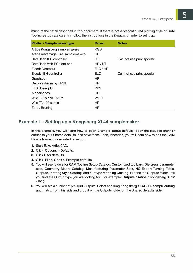
5ArtiosCAD Enterprise
95
much of the detail described in this document. If there is not a preconfigured plotting style or CAMTooling Setup catalog entry, follow the instructions in the Defaults chapter to set it up.
Plotter / Samplemaker type Driver Notes
Artios Kongsberg samplemakers KGB
Artios Advantage Line samplemakers HP
Data Tech IPC controller DT Can not use print spooler
Data Tech with PC front end HP / DT
Elcede Vectocut ELC / HP
Elcede IBH controller ELC Can not use print spooler
Graphtec HP
Devices driven by HPGL HP
LKS Speedplot PPS
Alphamerics HP
Wild TA2’s and TA10’s WILD
Wild TA-100 series HP
Zeta / Bruning HP
Example 1 - Setting up a Kongsberg XL44 samplemaker
In this example, you will learn how to open Example output defaults, copy the required entry orentries to your Shared defaults, and save them. Then, if needed, you will learn how to edit the CAMDevice Name to complete the setup.
1. Start Esko ArtiosCAD.2. Click Options > Defaults.3. Click User defaults.4. Click File > Open > Example defaults.5. You will see folders for CAM Tooling Setup Catalog, Customized toolbars, Die press parameter
sets, Geometry Macro Catalog, Manufacturing Parameter Sets, NC Export Turning Table,Outputs, Plotting Style Catalog, and Subtype Mapping Catalog. Expand the Outputs folder untilyou find the Output type you are looking for. (For example: Outputs / Artios / Kongsberg XL22- FC.)
6. You will see a number of pre-built Outputs. Select and drag Kongsberg XL44 - FC sample cuttingand matrix from this side and drop it on the Outputs folder on the Shared defaults side.

5ArtiosCAD Enterprise
96
7. Double-click the new entry and click the Directories tab. Change the directory entries to thedirectory that the Kongsberg front end computer will look in.
8. Click the View tab and note the contents of the Specify Plotting Style group. If the plotting styledoes not exist, its name will be surrounded by parentheses. If the plotting style name is notsurrounded by parentheses, click OK and proceed to step 12; otherwise, proceed to step 9.

5ArtiosCAD Enterprise
97
9. Click OK to exit this dialog box.10.Expand the Plotting Style Catalog in Shared Defaults by clicking the plus sign next to it.11.Look for the plotting style you noted as being used by the Kongsberg. Copy its definition from
the Example defaults in the same manner as you copied the definition for the Kongsberg.12.Make sure the Shared defaults button is selected. There will be an asterisk next to it indicating
that it has been modified and needs saving. Click File and then Save to do this. Confirm byclicking Yes.
13.Click File and then Exit to leave Defaults.
You have successfully set up a Kongsberg XL44 Samplemaker.
Example 2 - Setting up an Alphamerics RS-232 samplemaker
This type of plotter can use a Microsoft shared print spooler to route the data to the particularcomputer/port to which the device is connected. This is preferred over using a direct connection toa port on a specific computer since it allows the device to be accessed by anyone who has accessto the shared printer.
The first thing to do is set up the print spooler. Use a generic printer driver that does not modifydata, such as the IBM Graphics printer driver. This driver is part of the standard driver set providedwith the operating system.
1. Set up a printer on the appropriate port. Make sure that the baud rate and other RS-232 propertiesare set up to suit the plotter interface.
2. Let us assume that you have set up a shared printer on the computer called brunnhilde with ashare name of alphamerics. Add a networked printer to your system that points to that sharedprinter.
3. Follow the steps from Example 1, selecting the appropriate entry in Example CAM Outputs for TheAlphamerics Corp instead of Artios. Select the appropriate plotting style. (CAM.ALPHAMERICS)
4. Double-click the Output you just copied. Click the Device tab.5. Click the Browse button (...) at the end of the CAM Device Name: field to open the Output
Destinations dialog box.6. Expand the System Printers folder by clicking the plus sign (+) next to its name.7. Select the entry matching the printer queue, for example the \\brunnhilde\alphamerics entry, and
click OK.
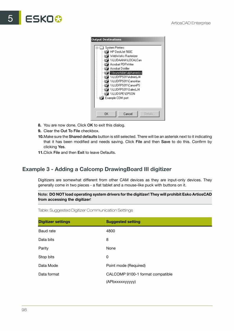
5ArtiosCAD Enterprise
98
8. You are now done. Click OK to exit this dialog.9. Clear the Out To File checkbox.10.Make sure the Shared defaults button is still selected. There will be an asterisk next to it indicating
that it has been modified and needs saving. Click File and then Save to do this. Confirm byclicking Yes.
11.Click File and then Exit to leave Defaults.
Example 3 - Adding a Calcomp DrawingBoard III digitizer
Digitizers are somewhat different from other CAM devices as they are input-only devices. Theygenerally come in two pieces - a flat tablet and a mouse-like puck with buttons on it.
Note: DO NOT load operating system drivers for the digitizer! They will prohibit Esko ArtiosCADfrom accessing the digitizer!
Table: Suggested Digitizer Communication Settings
Digitizer settings Suggested setting
Baud rate 4800
Data bits 8
Parity None
Stop bits 0
Data Mode Point mode (Required)
Data format CALCOMP 9100-1 format compatible
(APbxxxxxyyyyy)

5ArtiosCAD Enterprise
99
Digitizer settings Suggested setting
If choosing one of your own, it must be ASCII.
Digitizer step size 1000 lines/inch or 50 lines/mm
To install the digitizer, do the following:
1. Connect the digitizer to any free serial port (use COM1 for the purposes of this example) andsupply it with power. Configure it to match the communications settings listed above.
2. Create an Output Destination for this port and if the serial port is on a remote computer, makesure ArtiosIO is running on the remote machine.
3. Start Esko ArtiosCAD and then click Options > Defaults.4. Open the Digitizer Setup Catalog and select either Calcomp 16 Button or right-click and create
a new data item with the name of your digitizer.5. Select the Digitizer Parameters tab.
6. Make sure the correct Output Destination is selected in the CAM Device Name field.7. Make sure the settings in the Digitizer Step Size group match the settings on your digitizer.8. Press buttons 0, 1 and 2 on the puck. The Decoded Data group should look similar to the picture
shown below:
Look carefully at the third character in each line of data. Starting from the top, it should correspondto the button you pressed on the puck.
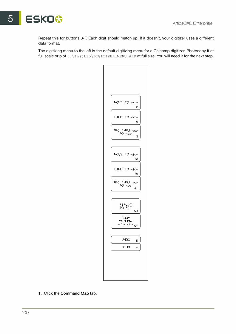
5ArtiosCAD Enterprise
100
Repeat this for buttons 3-F. Each digit should match up. If it doesn’t, your digitizer uses a differentdata format.
The digitizing menu to the left is the default digitizing menu for a Calcomp digitizer. Photocopy it atfull scale or plot ..\InstLib\DIGITIZER_MENU.ARD at full size. You will need it for the next step.
1. Click the Command Map tab.
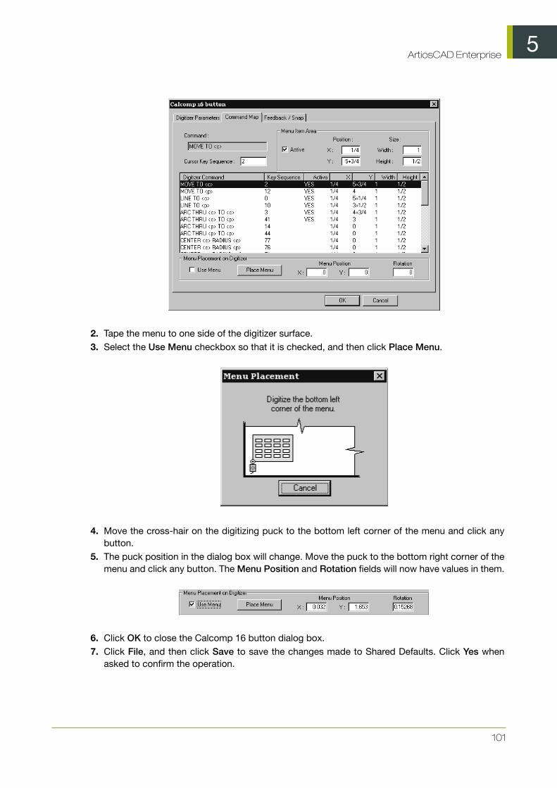
5ArtiosCAD Enterprise
101
2. Tape the menu to one side of the digitizer surface.3. Select the Use Menu checkbox so that it is checked, and then click Place Menu.
4. Move the cross-hair on the digitizing puck to the bottom left corner of the menu and click anybutton.
5. The puck position in the dialog box will change. Move the puck to the bottom right corner of themenu and click any button. The Menu Position and Rotation fields will now have values in them.
6. Click OK to close the Calcomp 16 button dialog box.7. Click File, and then click Save to save the changes made to Shared Defaults. Click Yes when
asked to confirm the operation.

5ArtiosCAD Enterprise
102
8. Exit Defaults. Your digitizer is now ready for use.
Advanced digitizer setup
Adding a non-Calcomp digitizer
If you are not using a Calcomp digitizer, the digitizer must meet these requirements:
• The digitizer must be connected via an RS-232C (serial) port on the PC.• The digitizer must be set to Point mode. This means that only one set of positional data is sent
when a puck button is pressed.• The data produced when a button on the puck is pressed must contain one or two characters
representing which button was pressed and also strings of numbers indicating the position ofthe puck when the button was pressed. The data sent must be ASCII, not binary, and must beseparated by a carriage return (CR), line feed (LF), or both (CR/LF).
While not required, Esko ArtiosCAD is easier to configure if the digitizer data is in a fixed format.
Once you have the digitizer connected, configured, and turned on, do the following:
1. Start Esko ArtiosCAD and then click Options > Defaults.2. Add an Output Destination for the port the digitizer is connected to.3. In the Shared Defaults pane, right-click the Digitizer Setup Catalog and click New, and then click
Data. Enter the name of the digitizer, press enter, and then double-click it to open its propertypage.
4. Select the proper Output Destination in the CAM Device Name: field.5. Press a few buttons on the digitizer puck. You should see some data appear in the Decoded
Data group.
The data format should be similar to one of the entries in the Data String column in the tablebelow. The letters b and c indicate button data and should always be a digit between 0–9 or aletter between A–F.
Table: Alternate Digitizer Data Formats
Data String Button ID X-Dataformat
Y-Dataformat
IDposition
Before After No. Fixed/Delim
No. Fixed/Delim
No.
2 0 1 F 5 F 5 ID x y

5ArtiosCAD Enterprise
103
Data String Button ID X-Dataformat
Y-Dataformat
IDposition
Before After No. Fixed/Delim
No. Fixed/Delim
No.
APb1111122222
APc5555566666
APb 1111 2222
Apc 5555 6666
2 0 1 F 5 F 5 ID x y
APbV +1234 -12
ApcV +5678 +123
2 1 1 F 6 F 6 ID x y
PQbb00012-00034+
PQcc00562+00029+
2 0 2 F 6 F 6 ID x y
123 456 b
197 1276 c
0 0 1 F 6 F 6 x y ID
b 123 345
c 1234 567
0 0 1 D D ID x y
123,456,b
87,10,c
0 0 1 D D x y ID
Once you have determined which format the data is in, set the options in the Format groupaccordingly.
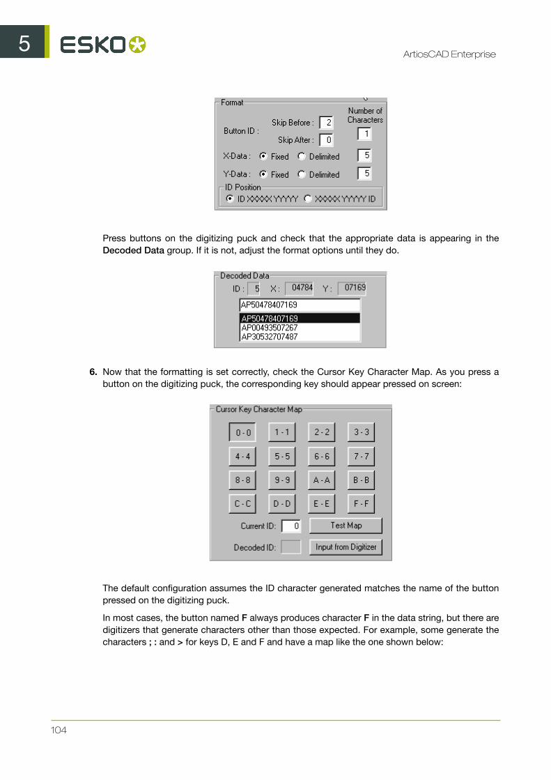
5ArtiosCAD Enterprise
104
Press buttons on the digitizing puck and check that the appropriate data is appearing in theDecoded Data group. If it is not, adjust the format options until they do.
6. Now that the formatting is set correctly, check the Cursor Key Character Map. As you press abutton on the digitizing puck, the corresponding key should appear pressed on screen:
The default configuration assumes the ID character generated matches the name of the buttonpressed on the digitizing puck.
In most cases, the button named F always produces character F in the data string, but there aredigitizers that generate characters other than those expected. For example, some generate thecharacters ; : and > for keys D, E and F and have a map like the one shown below:

5ArtiosCAD Enterprise
105
You can manually set the character map by clicking the on-screen button and replacing the valuein the Current ID field with the one or two characters produced by the digitizer when the buttonon the digitizing puck is pressed. Repeat this procedure for each button on the digitizing puck.
You can also set the character map using only the input from the digitizer. First, make sure theformatting is set correctly. Next, click the on-screen 0 button and then click Input from Digitizer.Click the 0 button on the digitizing puck to enter the value for 0. The 1 on-screen button will thenbe automatically selected, so press the 1 button on the digitizing puck. Repeat for the rest of thebuttons. If you make a mistake, simply click the on-screen button you wish to reprogram, andpress the appropriate button on the digitizing puck.
7. Now that the character mapping is configured, test it by clicking Test Map. As you press buttonson the digitizing puck, the corresponding on-screen buttons should appear pressed.
Adjusting the step size of the digitizer
Over time, you may notice that your digitized geometry is not as accurate as you desire. While yourdigitizer may be set to have 1000 lines of resolution per inch, by digitizing a 10-inch square withextreme accuracy which results in a 10.03 by 10.06-inch square in Esko ArtiosCAD, you realize thatit is out of calibration. The solution to this is to adjust the step size. Open the entry for the digitizerin Defaults and adjust the entries in the Digitizer Step Size group.
Using the values stated in the previous paragraph, change the 1000 in the drop-down list box to1003, click the Different in Y checkbox, and change the 1000 in that drop-down list box to 1006.
Configuring the Command Map
Digitizing has 26 commands. Each can be assigned a digitizer puck key sequence and/or a digitizerMenu Item Area. If you wish to use the command while digitizing, you must assign either a Key

5ArtiosCAD Enterprise
106
Sequence and/or a Menu Item Area to the command. (If you think you will never use some of thecommands, you may choose to leave them unassigned.)
The following abbreviations are used in the table below:
• <c> A coordinate on the digitizer.• <p> An existing point. These are the end points (and intersection points) of existing lines in the
current design whether just digitized, or part of the original structure. To select such a point, youmust digitize a point on the digitizer within snap distance of one of these points.
• <l> An existing line. To select such a line, you must digitize a point on the digitizer within snapdistance of an existing line in the design.
Table: Digitizer Commands
Key sequence Command
2 MOVE TO <c>
12 MOVE TO <p>
0 LINE TO <c>
10 LINE TO <p>
3 ARC THROUGH <c> TO <c>
41 ARC THROUGH <c> TO <p>
14 ARC THROUGH <p> TO <c>
44 ARC THROUGH <p> TO <p>
77 CENTER <c> RADIUS <c>
76 CENTER <c> RADIUS <p>
7A CENTER <c> RADIUS radius
66 CENTER <p> RADIUS <c>
67 CENTER <p> RADIUS <p>
6A CENTER <p> RADIUS radius
52 INTERSECT <l> <l>
51 INTERSECT <l> <l> KEEP 1st
BBB BLEND <l> <l> THROUGH <c>
BB1 BLEND <l> <l> THROUGH <p>
BBA BLEND <l> <l> RADIUS radius
D DELETE <l>
E UNDO

5ArtiosCAD Enterprise
107
Key sequence Command
F REDO
CD REPLOT - SCALE TO FIT
CC REPLOT - CURRENT SCALE
CA ZOOM BACK
CF ZOOM WINDOW <c> <c>
All of these commands are mapped in the Command Map tab of the digitizer’s property page inDefaults.
To set a key sequence, select the command you wish to assign to the key, and then type the keysequence to use it with in the Cursor Key Sequence field.
The sequence must be comprised of the characters 0–9 A–F. It may be up to six characters long.
A key sequence must be unique and may not mask another command. For example, if you wish touse the Key Sequence 2 for a command, no other Key Sequence may start with 2. This is because2 by itself matches a command, and therefore masks a key sequence like 21.
The exception to this is when two commands differ only in what is selected — a coordinate, a point,or a line. In this case the commands may share a command sequence. If this is used, the commandwill snap to a point if one is within snap distance, or to a coordinate if one is not.
While editing this property page, you may temporarily have conflicts as described above. This is soyou can easily change Key Sequences, or swap them to different commands. However, you will bewarned about them as they are created. You may not exit the property page without resolving suchconflicts.
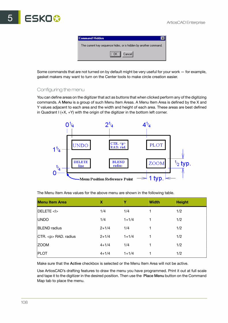
5ArtiosCAD Enterprise
108
Some commands that are not turned on by default might be very useful for your work — for example,gasket makers may want to turn on the Center tools to make circle creation easier.
Configuring the menu
You can define areas on the digitizer that act as buttons that when clicked perform any of the digitizingcommands. A Menu is a group of such Menu Item Areas. A Menu Item Area is defined by the X andY values adjacent to each area and the width and height of each area. These areas are best definedin Quadrant I (+X, +Y) with the origin of the digitizer in the bottom left corner.
The Menu Item Area values for the above menu are shown in the following table.
Menu Item Area X Y Width Height
DELETE <l> 1/4 1/4 1 1/2
UNDO 1/4 1+1/4 1 1/2
BLEND radius 2+1/4 1/4 1 1/2
CTR. <p> RAD. radius 2+1/4 1+1/4 1 1/2
ZOOM 4+1/4 1/4 1 1/2
PLOT 4+1/4 1+1/4 1 1/2
Make sure that the Active checkbox is selected or the Menu Item Area will not be active.
Use ArtiosCAD’s drafting features to draw the menu you have programmed. Print it out at full scaleand tape it to the digitizer in the desired position. Then use the Place Menu button on the CommandMap tab to place the menu.

5ArtiosCAD Enterprise
109
Configuring Feedback and Snap
The Feedback/Snap tab of the digitizer’s Properties dialog box lets you set the snap tolerance ofthe digitizer, the default radius, and the sounds heard when digitizing.
When digitizing a point to satisfy a snap point <p> or a snap line <l>, you need to be within theSnap Tolerance. If you are working on large corrugated designs, you may wish to set this value tosomething like a quarter-inch or five millimeters. Since the command indicates whether a snap point/line is expected, this value can be considerably larger than the normal screen snap value.
The Default radius field is used by some of the BLEND and CENTER commands. Set a sensibledefault; it is easily changed while digitizing.
The Feedback / Sounds group controls the audible feedback generated while digitizing. There arefive types of feedback. Windows Sounds require a sound card in the computer; beeps can be madeby most computers.
Table: Digitizing Feedback
Type of feedback Meaning
Data Received Data received from the digitizer.
If your digitizer beeps when a puck button is pressed, youmay wish to turn this off.
Command OK The command was successful.
Snap Point/Line error You were too far away for a snap point <p> or snap line<l> to be found.
Command not recognized The key sequence does not match any of those defined.

5ArtiosCAD Enterprise
110
Type of feedback Meaning
Geometry Error The command failed because the geometry could not beperformed. (e.g. A blend would not fit.)
The fields in the Windows Sounds column designate which sound to use as defined in the Soundscontrol panel applet.
When clicked, the triangle button plays a sample of the sound or beep.
The ellipsis button lets you browse for a different sound file.
The frequency and the duration of the beeps can be set using the appropriate fields.

6ArtiosCAD Enterprise
111
6. Other tasks
Uninstalling Esko ArtiosCAD
Uninstall Esko ArtiosCADn.nnll by using the Add/Remove Programs applet in Control Panel. Select itin the list of programs, click Change, click Next, choose the Remove option, and follow the prompts.
Removing individual Esko ArtiosCAD Programs
To remove individual parts of Esko ArtiosCAD such as the PDF Import/Export feature, perform aModify and de-select the ArtiosCAD Programs to remove. After uninstallation there may be files fromthese components left behind in the \Esko\Artios and \Esko\Artios\ArtiosCADn.nnll folders; thesefiles may be safely deleted if desired after all Esko ArtiosCAD versions are removed.
Uninstalling SolidWorks separately from Esko ArtiosCAD
If you have purchased the SolidWorks option and need to remove the SolidWorks OriginalEquipment Manufacturer software without uninstalling Esko ArtiosCAD, run \ArtiosCAD\SolidWorksRemove.bat on disk 1 of the Esko ArtiosCAD media. SolidWorks OEM software isnormally removed when the version of Esko ArtiosCAD that installed it is removed and no otherversions of Esko ArtiosCAD are using it. This is different from removing the SolidWorks Import/Exportcomponent of ArtiosCAD in that it actually deletes the SolidWorks software from the system, not justthe portions of ArtiosCAD that interface with it.
Removing MSDE
Uninstall the Esko ArtiosCAD MSDE database program files by using the Add/Remove Programsapplet in Control Panel. Select Microsoft SQL Server Desktop Engine (ARTIOSCADDB) from thelist of installed programs and click Remove.
Uninstalling the database software does not remove the database data files stored in ..\Esko\Artios\DataCenter\MSDE. This is intentional in case you want to resume using MSDE. If you

6ArtiosCAD Enterprise
112
will not be using MSDE again, you may delete the ..\Esko\Artios\DataCenter\MSDE folderand its contents.
Removing the Esko ArtiosCAD ODBC entry
Once all versions of Esko ArtiosCAD are removed, open the ODBC/Data Sources applet in ControlPanel > Administrative Tools, click the System DSN tab, and remove the Esko ArtiosCAD datasourceentry by selecting ArtiosCAD and clicking Remove.
You must remove the existing Esko ArtiosCAD ODBC entry after uninstalling all versions of EskoArtiosCAD if you wish to change Esko ArtiosCAD database types in a subsequent installation.
Uninstalling a patch
To uninstall a patch when using Windows XP Service Pack 2 or greater, remove that particular buildthrough Add/Remove Programs (making sure Show Updates is checked).
To uninstall a patch when using an operating system earlier than Windows XP Service Pack 2, clickthe Remove ArtiosCAD N.nnll_bbb choice in the ArtiosCAD folder on the Start menu.
Esko ArtiosCAD will revert to the build that was present before the patch was loaded.
Modifying and Repairing Esko ArtiosCAD
You can modify or repair the Esko ArtiosCAD installation by clicking Change in the Add/RemovePrograms applet in Control Panel, and then by choosing Modify or Repair. You must use theoriginal Esko ArtiosCAD media, or use the same network location, as when you first installedthe software.
Modify allows you to change the installed features and options as if you were performing anAdvanced installation.
Repair looks for missing or corrupt files and replaces them as necessary. It will not overwrite Defaults.You will be given the same License Disk options as when you first installed the software. If you aretrying to repair the licensing information choose Yes, I have licensing information to apply and usethe licensing diskette, otherwise choose License information already applied or unavailable to keepyour current licensing information.
Loading an Esko ArtiosCAD patch
Esko ArtiosCAD patches are installed using a single executable file. To install a patch, do thefollowing:
1. Log on as Administrator, or as a user with local administrative privileges.2. Using Windows Explorer, double-click the patch file. Patch files are named ArtiosCAD<version
and build number>.exe, such as ArtiosCAD7.1Build497.exe.
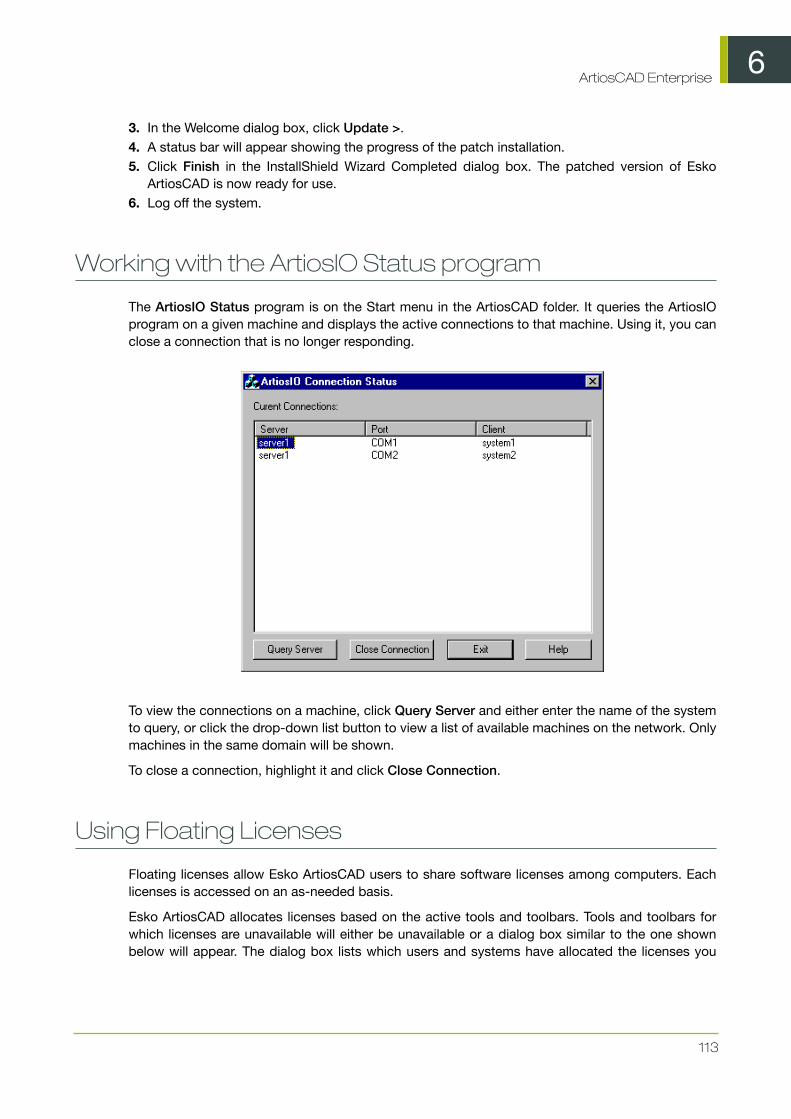
6ArtiosCAD Enterprise
113
3. In the Welcome dialog box, click Update >.4. A status bar will appear showing the progress of the patch installation.5. Click Finish in the InstallShield Wizard Completed dialog box. The patched version of Esko
ArtiosCAD is now ready for use.6. Log off the system.
Working with the ArtiosIO Status program
The ArtiosIO Status program is on the Start menu in the ArtiosCAD folder. It queries the ArtiosIOprogram on a given machine and displays the active connections to that machine. Using it, you canclose a connection that is no longer responding.
To view the connections on a machine, click Query Server and either enter the name of the systemto query, or click the drop-down list button to view a list of available machines on the network. Onlymachines in the same domain will be shown.
To close a connection, highlight it and click Close Connection.
Using Floating Licenses
Floating licenses allow Esko ArtiosCAD users to share software licenses among computers. Eachlicenses is accessed on an as-needed basis.
Esko ArtiosCAD allocates licenses based on the active tools and toolbars. Tools and toolbars forwhich licenses are unavailable will either be unavailable or a dialog box similar to the one shownbelow will appear. The dialog box lists which users and systems have allocated the licenses you
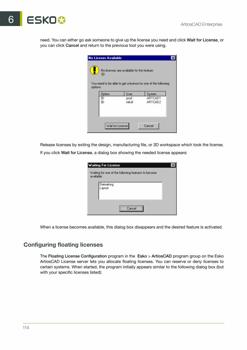
6ArtiosCAD Enterprise
114
need. You can either go ask someone to give up the license you need and click Wait for License, oryou can click Cancel and return to the previous tool you were using.
Release licenses by exiting the design, manufacturing file, or 3D workspace which took the license.
If you click Wait for License, a dialog box showing the needed license appears:
When a license becomes available, this dialog box disappears and the desired feature is activated.
Configuring floating licenses
The Floating License Configuration program in the Esko > ArtiosCAD program group on the EskoArtiosCAD License server lets you allocate floating licenses. You can reserve or deny licenses tocertain systems. When started, the program initially appears similar to the following dialog box (butwith your specific licenses listed):
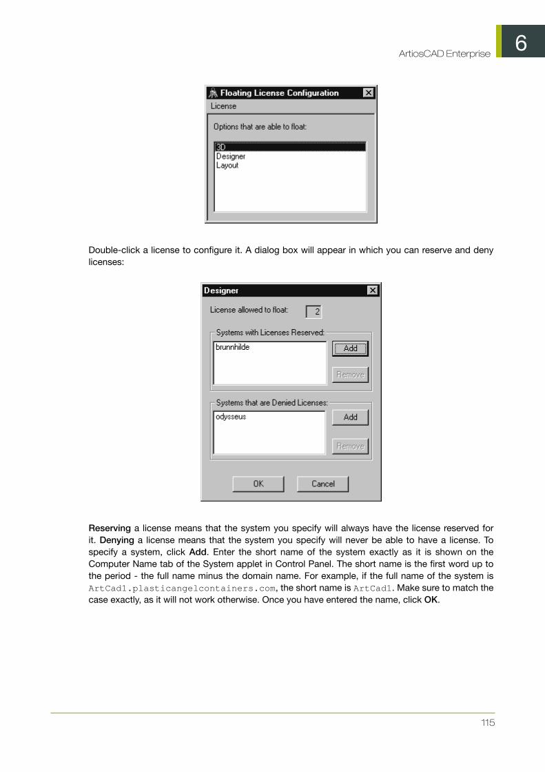
6ArtiosCAD Enterprise
115
Double-click a license to configure it. A dialog box will appear in which you can reserve and denylicenses:
Reserving a license means that the system you specify will always have the license reserved forit. Denying a license means that the system you specify will never be able to have a license. Tospecify a system, click Add. Enter the short name of the system exactly as it is shown on theComputer Name tab of the System applet in Control Panel. The short name is the first word up tothe period - the full name minus the domain name. For example, if the full name of the system isArtCad1.plasticangelcontainers.com, the short name is ArtCad1. Make sure to match thecase exactly, as it will not work otherwise. Once you have entered the name, click OK.

6ArtiosCAD Enterprise
116
To remove a system from either the Reserved or Denied lists, select it, click Remove, and click OK.
When you have finished configuring the license as desired, click OK to return to the Floating LicenseConfiguration dialog box, or click Cancel to ignore the changes you made.
To exit the Floating License Configuration dialog box, click License, and then click Exit.
Note: If you have made changes to the configuration, the License Manager will be shut downand restarted when you exit the Floating License Configuration program. It takes the Elan LicenseManager three minutes to restart after shutting down.
Troubleshooting
If you have trouble using a desired feature and get a dialog box like the one below, use either theArtiosLM applet in Control Panel or the ArtiosCAD License Management utility on the Esko ArtiosCADLicense server to make sure the server is running.
If the Floating License Utility does not start, it is because there are no floating licenses to configure.

6ArtiosCAD Enterprise
117
Upgrading Esko ArtiosCAD Licenses
Esko ArtiosCAD licenses enable you to use the features you have bought and disable the featuresyou have not bought. As your needs change, you may have to change your licenses accordingly.
When you upgrade a license, you usally receive a licensing file by e-mail. You then have to installthat file properly as described in the following section.
You must log on to your system with administrative privileges to upgrade licenses.
Note: NO SYSTEM MAY HAVE INSTANCES OF WebCenter, Esko ArtiosCAD, DataCenter Admin,OR Esko SpecLink OPEN WHEN UPGRADING LICENSES!
License Manager: keyless
To upgrade a keyless license for the FlexNet license manager, do the following;
1. Save the licensing file sent to you by Esko in a place where you can access it from the machinewhose license you will be upgrading, for example a network location, on a USB thumb drive, andso forth.
2. On the machine with the license to upgrade, log in as Administrator or as a user withadministrative privileges.
3. Click Start > Programs/All Programs > Esko > ArtiosCAD > Activate Local Licenses/ActivateServer Licenses.
4. In the Esko (Local or Server) License Manager dialog box, click Activate.
5. Click Next in the Activate License Wizard dialog box.
6. In the On-line activation or off-line activation dialog box, choose either On-line activation or Off-line activation as appropriate for your system and click Next.
7. In the Your product keys dialog box, choose I have a file containing one or more product keysand click Next.
8. In the File containing your product keys dialog box, browse for the file you saved in step 1 andclick Next.
9. In the Esko Account dialog box, enter your Esko licensing account name and password and clickNext.
10.In the Activation completed successfully dialog box, the license(s) you activated should appear.Click Finish to complete the license upgrade.
11.Optionally, click Save Licenses Report to save a report of the license upgrade for your records.
12.Close the license manager dialog box by clicking the X in the upper right corner and test the newlicense as desired.
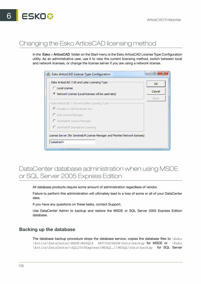
6ArtiosCAD Enterprise
118
Changing the Esko ArtiosCAD licensing method
In the Esko > ArtiosCAD folder on the Start menu is the Esko ArtiosCAD License Type Configurationutility. As an administrative user, use it to view the current licensing method, switch between localand network licenses, or change the license server if you are using a network license.
DataCenter database administration when using MSDEor SQL Server 2005 Express Edition
All database products require some amount of administration regardless of vendor.
Failure to perform this administration will ultimately lead to a loss of some or all of your DataCenterdata.
If you have any questions on these tasks, contact Support.
Use DataCenter Admin to backup and restore the MSDE or SQL Server 2005 Express Editiondatabase.
Backing up the database
The database backup procedure stops the database service, copies the database files to \Esko\Artios\DataCenter\MSDE\MSSQL$ ARTIOSCADDB\Data\backup for MSDE or \Esko\Artios\DataCenter\SQL2005Express\MSSQL.1\MSSQL\Data\backup for SQL Server
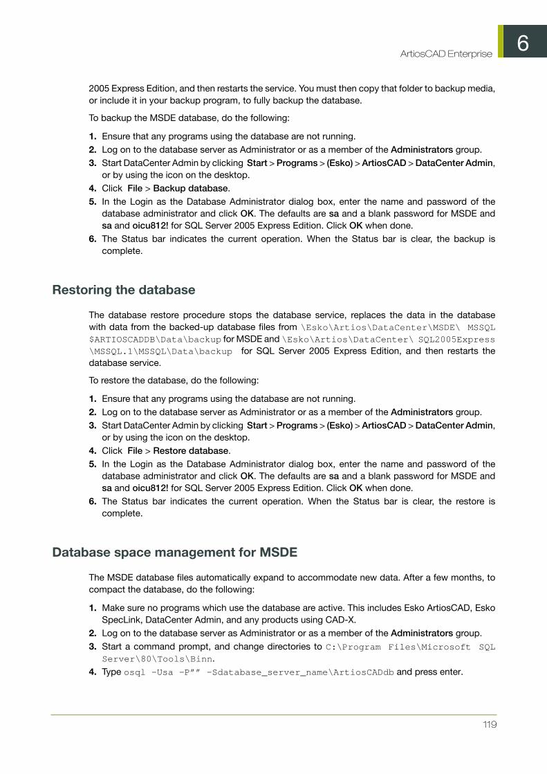
6ArtiosCAD Enterprise
119
2005 Express Edition, and then restarts the service. You must then copy that folder to backup media,or include it in your backup program, to fully backup the database.
To backup the MSDE database, do the following:
1. Ensure that any programs using the database are not running.2. Log on to the database server as Administrator or as a member of the Administrators group.3. Start DataCenter Admin by clicking Start > Programs > (Esko) > ArtiosCAD > DataCenter Admin,
or by using the icon on the desktop.4. Click File > Backup database.5. In the Login as the Database Administrator dialog box, enter the name and password of the
database administrator and click OK. The defaults are sa and a blank password for MSDE andsa and oicu812! for SQL Server 2005 Express Edition. Click OK when done.
6. The Status bar indicates the current operation. When the Status bar is clear, the backup iscomplete.
Restoring the database
The database restore procedure stops the database service, replaces the data in the databasewith data from the backed-up database files from \Esko\Artios\DataCenter\MSDE\ MSSQL$ARTIOSCADDB\Data\backup for MSDE and \Esko\Artios\DataCenter\ SQL2005Express\MSSQL.1\MSSQL\Data\backup for SQL Server 2005 Express Edition, and then restarts thedatabase service.
To restore the database, do the following:
1. Ensure that any programs using the database are not running.2. Log on to the database server as Administrator or as a member of the Administrators group.3. Start DataCenter Admin by clicking Start > Programs > (Esko) > ArtiosCAD > DataCenter Admin,
or by using the icon on the desktop.4. Click File > Restore database.5. In the Login as the Database Administrator dialog box, enter the name and password of the
database administrator and click OK. The defaults are sa and a blank password for MSDE andsa and oicu812! for SQL Server 2005 Express Edition. Click OK when done.
6. The Status bar indicates the current operation. When the Status bar is clear, the restore iscomplete.
Database space management for MSDE
The MSDE database files automatically expand to accommodate new data. After a few months, tocompact the database, do the following:
1. Make sure no programs which use the database are active. This includes Esko ArtiosCAD, EskoSpecLink, DataCenter Admin, and any products using CAD-X.
2. Log on to the database server as Administrator or as a member of the Administrators group.3. Start a command prompt, and change directories to C:\Program Files\Microsoft SQL
Server\80\Tools\Binn.4. Type osql -Usa -P”” -Sdatabase_server_name\ArtiosCADdb and press enter.

6ArtiosCAD Enterprise
120
5. At the 1> prompt, type use ArtiosCADdb and press enter.6. At the 2> prompt, type go and press enter.7. At the 1> prompt, type dbcc shrinkfile (acaddata) and press enter.8. At the 2> prompt, type go and press enter.9. At the 1> prompt, type dbcc shrinkfile (acadlog) and press enter.10.At the 2> prompt, type go and press enter.11.At the 1> prompt, type exit and press enter.
Your screen should look similar to the one shown below.
MSDE-related Application Log entries in Event Viewer
On the database server, the MSSQL$ARTIOSCADDB service writes warning entries of category (8)to the Application Log in Event Viewer. They are about connecting to Active Directory and can beignored.
Using Microsoft SQL Server 2005
Microsoft SQL Server 2005 is a large, robust database which can require complex administration. Theinstallation documentation provided below is provided as a convenience only for initial installation.A dedicated Database Administrator (DBA) is required to administer and maintain the database, andis free to choose options other than those documented to meet local site requirements
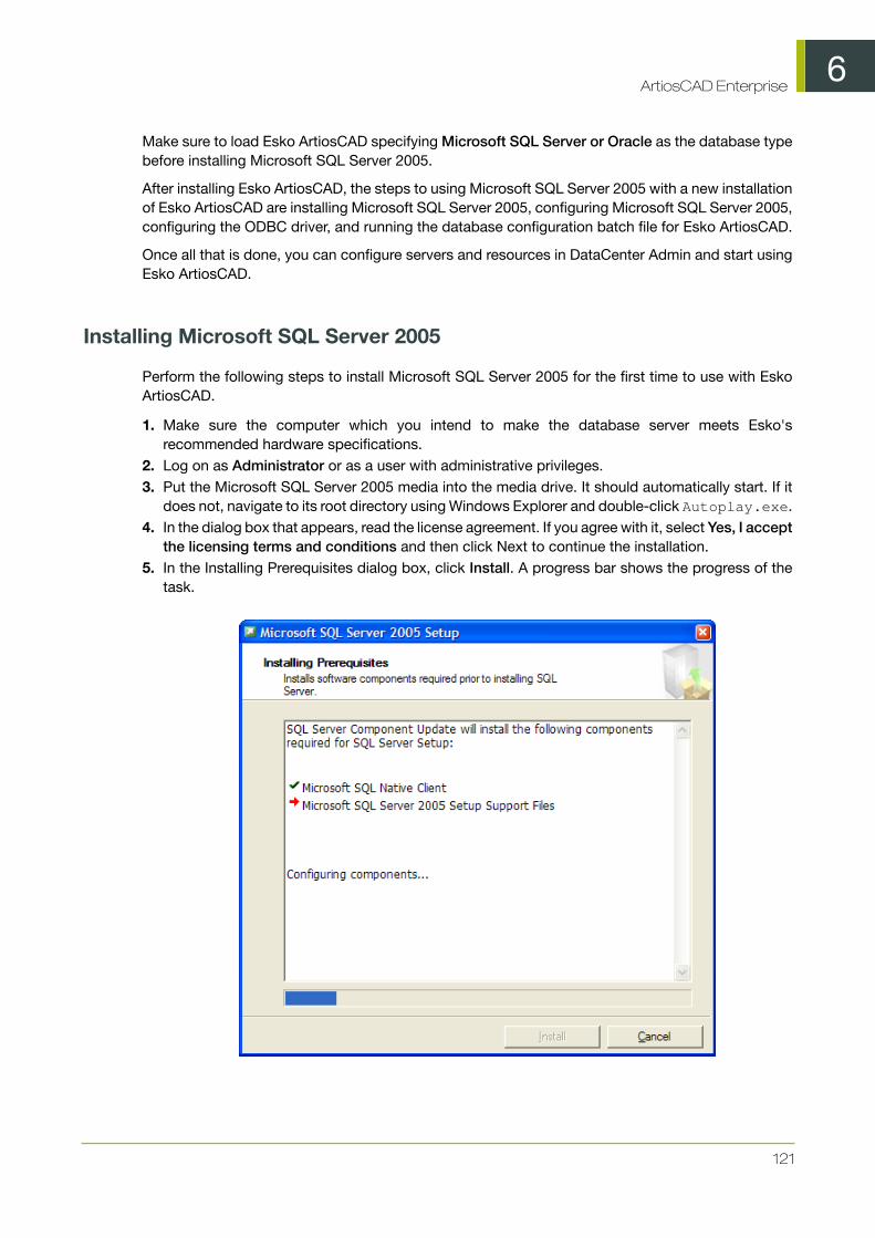
6ArtiosCAD Enterprise
121
Make sure to load Esko ArtiosCAD specifying Microsoft SQL Server or Oracle as the database typebefore installing Microsoft SQL Server 2005.
After installing Esko ArtiosCAD, the steps to using Microsoft SQL Server 2005 with a new installationof Esko ArtiosCAD are installing Microsoft SQL Server 2005, configuring Microsoft SQL Server 2005,configuring the ODBC driver, and running the database configuration batch file for Esko ArtiosCAD.
Once all that is done, you can configure servers and resources in DataCenter Admin and start usingEsko ArtiosCAD.
Installing Microsoft SQL Server 2005
Perform the following steps to install Microsoft SQL Server 2005 for the first time to use with EskoArtiosCAD.
1. Make sure the computer which you intend to make the database server meets Esko'srecommended hardware specifications.
2. Log on as Administrator or as a user with administrative privileges.3. Put the Microsoft SQL Server 2005 media into the media drive. It should automatically start. If it
does not, navigate to its root directory using Windows Explorer and double-click Autoplay.exe.4. In the dialog box that appears, read the license agreement. If you agree with it, select Yes, I accept
the licensing terms and conditions and then click Next to continue the installation.5. In the Installing Prerequisites dialog box, click Install. A progress bar shows the progress of the
task.
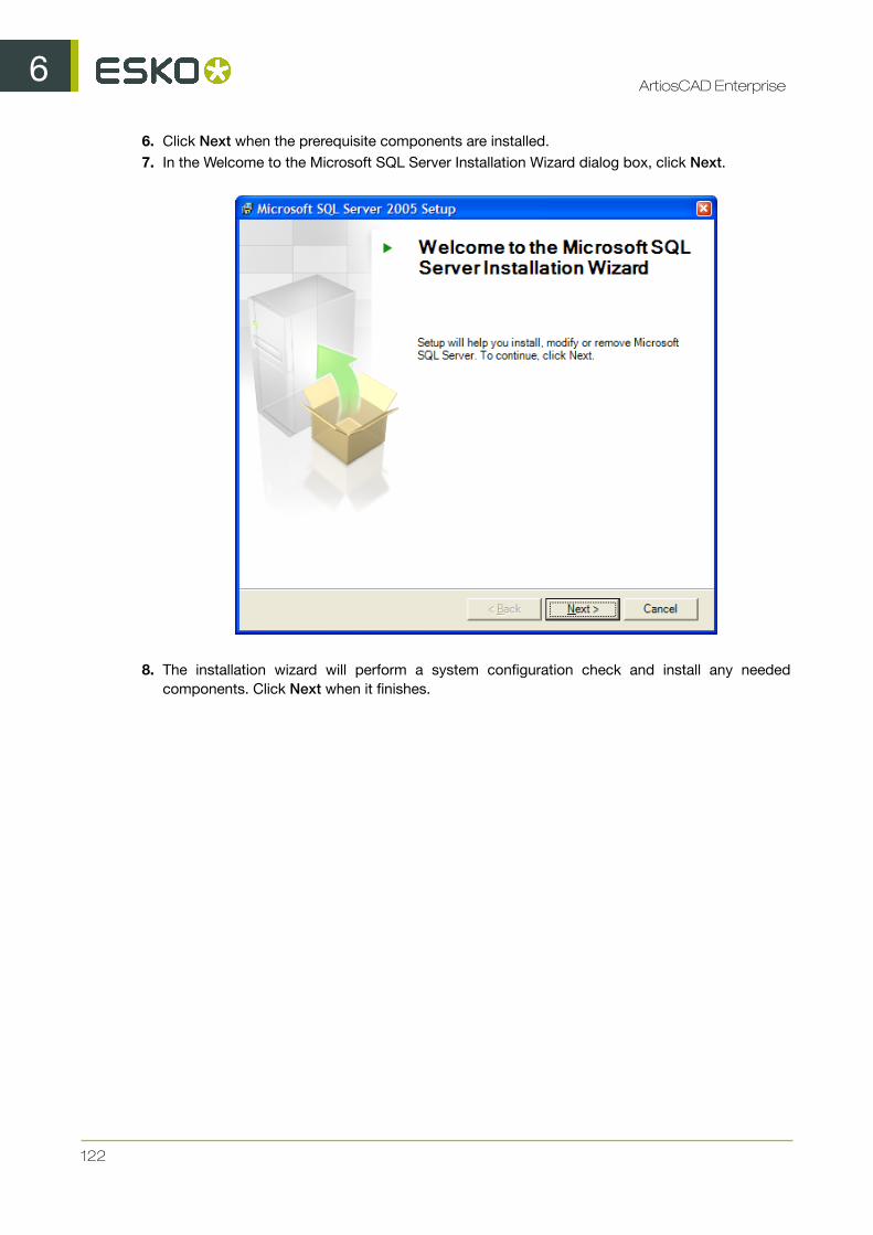
6ArtiosCAD Enterprise
122
6. Click Next when the prerequisite components are installed.7. In the Welcome to the Microsoft SQL Server Installation Wizard dialog box, click Next.
8. The installation wizard will perform a system configuration check and install any neededcomponents. Click Next when it finishes.
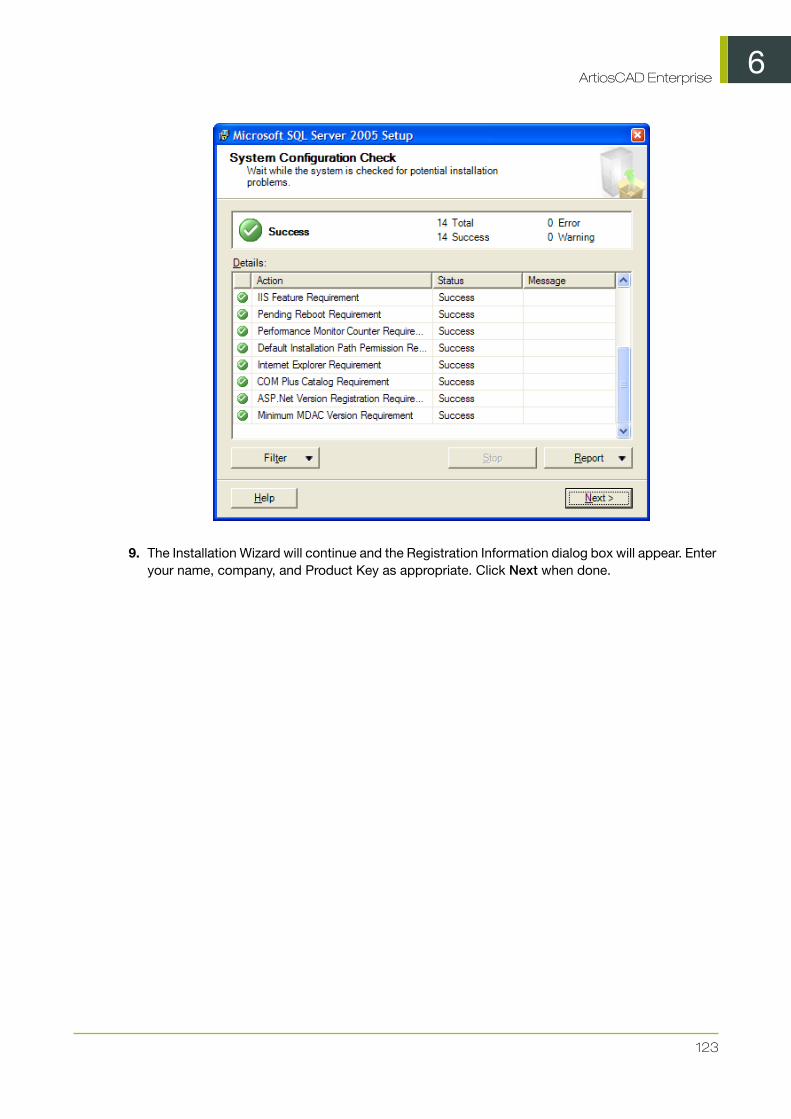
6ArtiosCAD Enterprise
123
9. The Installation Wizard will continue and the Registration Information dialog box will appear. Enteryour name, company, and Product Key as appropriate. Click Next when done.
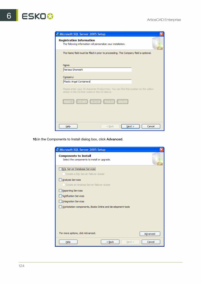
6ArtiosCAD Enterprise
124
10.In the Components to Install dialog box, click Advanced.

6ArtiosCAD Enterprise
125
11.In the Feature Selection dialog box, click the box next to Database Services and click Entirefeature will be installed on the hard drive.
12.Still in the Feature Selection dialog box, expand the Client Components catalog, click the box boxnext to Connectivity Components, and click Entire feature will be installed on the hard drive. Dothe same for Management Tools and click Next.
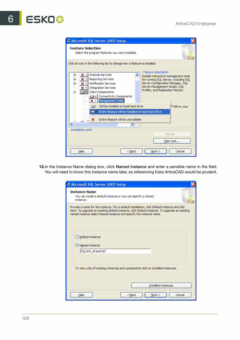
6ArtiosCAD Enterprise
126
13.In the Instance Name dialog box, click Named instance and enter a sensible name in the field.You will need to know this instance name later, so referencing Esko ArtiosCAD would be prudent.
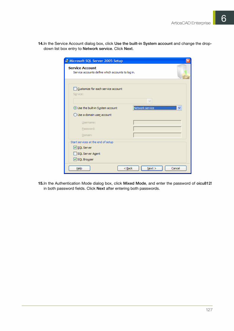
6ArtiosCAD Enterprise
127
14.In the Service Account dialog box, click Use the built-in System account and change the drop-down list box entry to Network service. Click Next.
15.In the Authentication Mode dialog box, click Mixed Mode, and enter the password of oicu812!in both password fields. Click Next after entering both passwords.
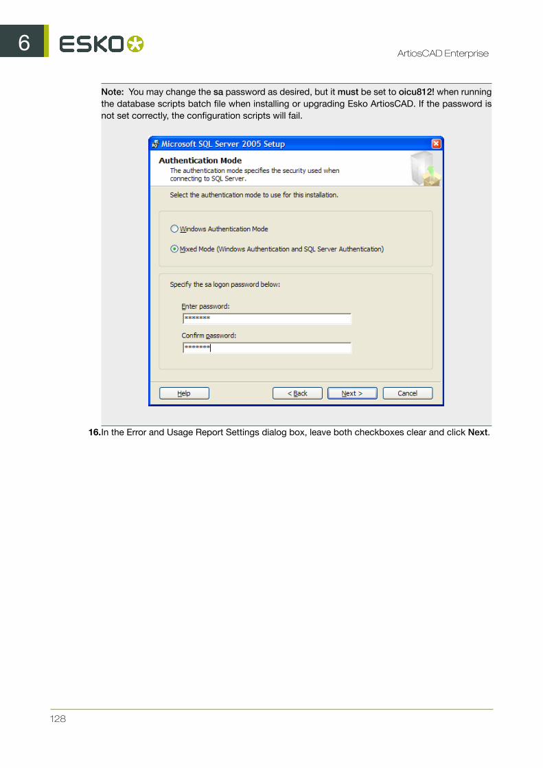
6ArtiosCAD Enterprise
128
Note: You may change the sa password as desired, but it must be set to oicu812! when runningthe database scripts batch file when installing or upgrading Esko ArtiosCAD. If the password isnot set correctly, the configuration scripts will fail.
16.In the Error and Usage Report Settings dialog box, leave both checkboxes clear and click Next.

6ArtiosCAD Enterprise
129
17.In the Ready to Install dialog box, click Install to begin the installation.
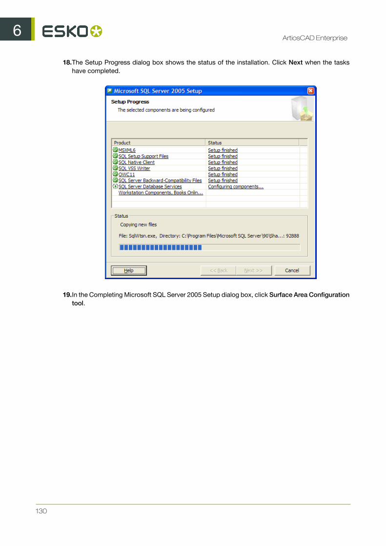
6ArtiosCAD Enterprise
130
18.The Setup Progress dialog box shows the status of the installation. Click Next when the taskshave completed.
19.In the Completing Microsoft SQL Server 2005 Setup dialog box, click Surface Area Configurationtool.
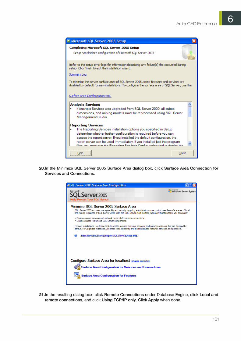
6ArtiosCAD Enterprise
131
20.In the Minimize SQL Server 2005 Surface Area dialog box, click Surface Area Connection forServices and Connections.
21.In the resulting dialog box, click Remote Connections under Database Engine, click Local andremote connections, and click Using TCP/IP only. Click Apply when done.

6ArtiosCAD Enterprise
132
22.In the Connection Settings Change Alert dialog box, click OK.
23.Click Service under Database Engine.24.Click Stop, then Start to restart the database engine service.25.Click OK to exit the Surface Area Configuration for Services and Connections dialog box.26.Close the SQL Server 2005 Surface Area Configuration dialog box.27.In the Microsoft SQL Server 2005 Setup dialog box, click Finish. Reboot the system if prompted
to do so. Do not postpone this reboot.
Note: At this point, apply the latest Microsoft SQL Server 2005 service packs and patches availablefrom the Microsoft web site athttp://www.microsoft.com/sql/default.mspx.
Configuring Microsoft SQL Server 2005
Once you have updated and patched Microsoft SQL Server 2005 appropriately, continue as follows.You may have to start the database by hand by right-clicking the SQL Server icon in the system trayand selecting MSSQLServer - Start.
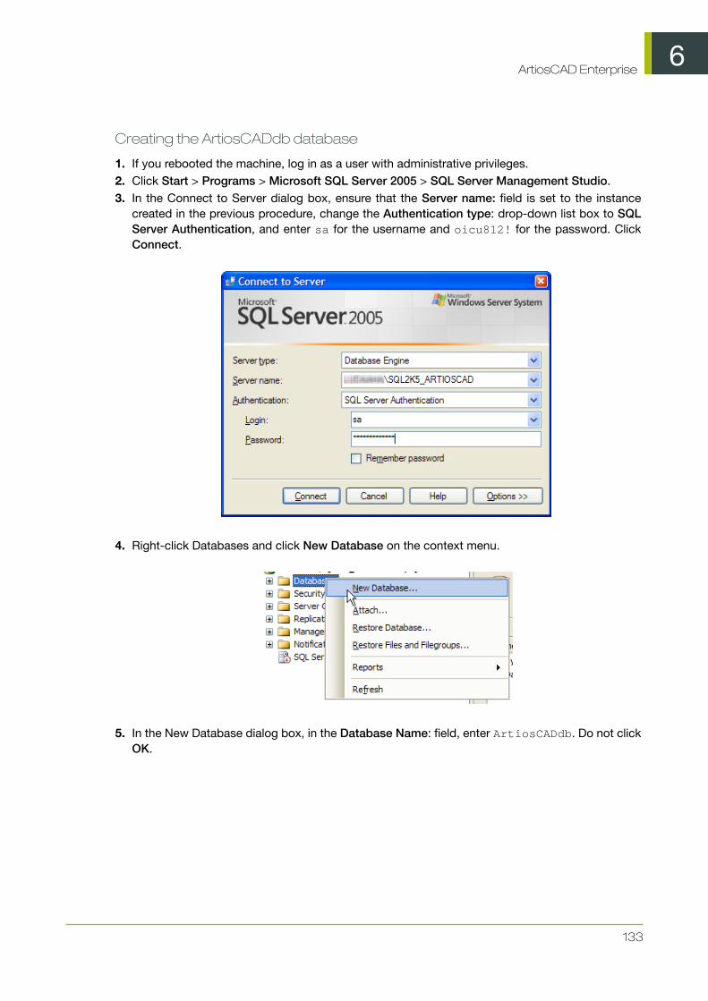
6ArtiosCAD Enterprise
133
Creating the ArtiosCADdb database
1. If you rebooted the machine, log in as a user with administrative privileges.2. Click Start > Programs > Microsoft SQL Server 2005 > SQL Server Management Studio.3. In the Connect to Server dialog box, ensure that the Server name: field is set to the instance
created in the previous procedure, change the Authentication type: drop-down list box to SQLServer Authentication, and enter sa for the username and oicu812! for the password. ClickConnect.
4. Right-click Databases and click New Database on the context menu.
5. In the New Database dialog box, in the Database Name: field, enter ArtiosCADdb. Do not clickOK.

6ArtiosCAD Enterprise
134
6. Click the 3 in the Initial size (MB) column and change it to 10. Do not click OK.
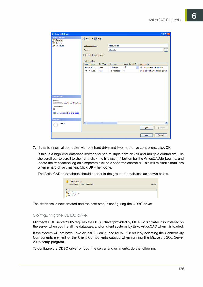
6ArtiosCAD Enterprise
135
7. If this is a normal computer with one hard drive and two hard drive controllers, click OK.
If this is a high-end database server and has multiple hard drives and multiple controllers, usethe scroll bar to scroll to the right, click the Browse (...) button for the ArtiosCADdb Log file, andlocate the transaction log on a separate disk on a separate controller. This will minimize data losswhen a hard drive crashes. Click OK when done.
The ArtiosCADdb database should appear in the group of databases as shown below.
The database is now created and the next step is configuring the ODBC driver.
Configuring the ODBC driver
Microsoft SQL Server 2005 requires the ODBC driver provided by MDAC 2.8 or later. It is installed onthe server when you install the database, and on client systems by Esko ArtiosCAD when it is loaded.
If the system will not have Esko ArtiosCAD on it, load MDAC 2.8 on it by selecting the ConnectivityComponents element of the Client Components catalog when running the Microsoft SQL Server2005 setup program.
To configure the ODBC driver on both the server and on clients, do the following:
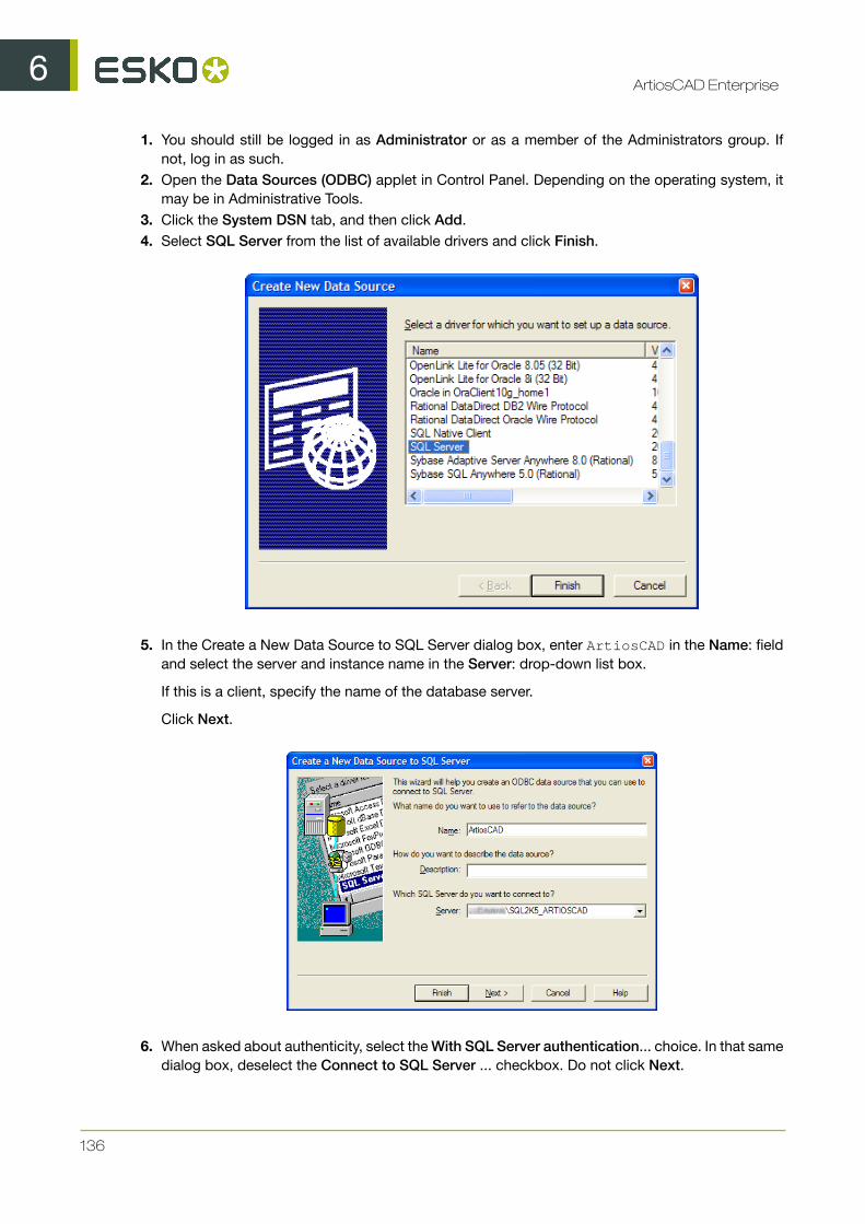
6ArtiosCAD Enterprise
136
1. You should still be logged in as Administrator or as a member of the Administrators group. Ifnot, log in as such.
2. Open the Data Sources (ODBC) applet in Control Panel. Depending on the operating system, itmay be in Administrative Tools.
3. Click the System DSN tab, and then click Add.4. Select SQL Server from the list of available drivers and click Finish.
5. In the Create a New Data Source to SQL Server dialog box, enter ArtiosCAD in the Name: fieldand select the server and instance name in the Server: drop-down list box.
If this is a client, specify the name of the database server.
Click Next.
6. When asked about authenticity, select the With SQL Server authentication... choice. In that samedialog box, deselect the Connect to SQL Server ... checkbox. Do not click Next.
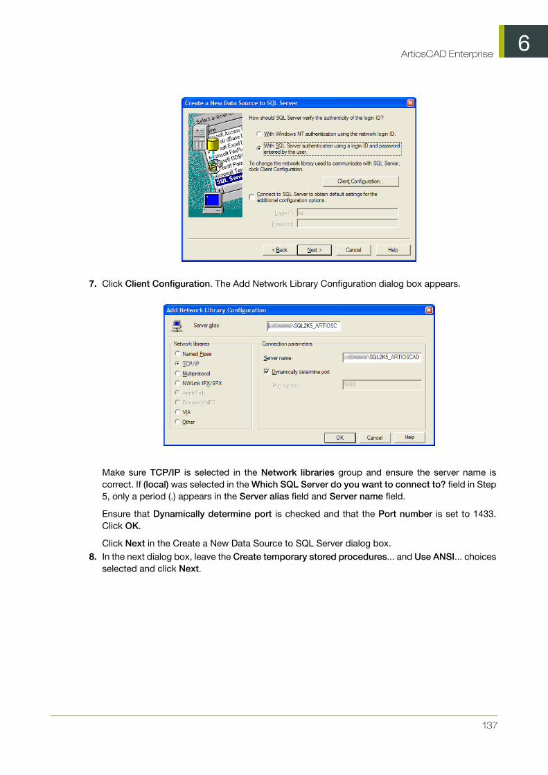
6ArtiosCAD Enterprise
137
7. Click Client Configuration. The Add Network Library Configuration dialog box appears.
Make sure TCP/IP is selected in the Network libraries group and ensure the server name iscorrect. If (local) was selected in the Which SQL Server do you want to connect to? field in Step5, only a period (.) appears in the Server alias field and Server name field.
Ensure that Dynamically determine port is checked and that the Port number is set to 1433.Click OK.
Click Next in the Create a New Data Source to SQL Server dialog box.8. In the next dialog box, leave the Create temporary stored procedures... and Use ANSI... choices
selected and click Next.

6ArtiosCAD Enterprise
138
9. In the next dialog box, leave Perform translation for character data selected.
If the system is using non-U.S. locale settings, check the Change the language of SQL Serversystem messages to: checkbox and set the value to English.
Click Finish.
10.The ODBC Microsoft SQL Server Setup dialog box will appear showing a summary of theconfiguration. Click OK. Do not test the configuration; it will fail because the proper database useris not configured because the database configuration batch file has not yet been run.
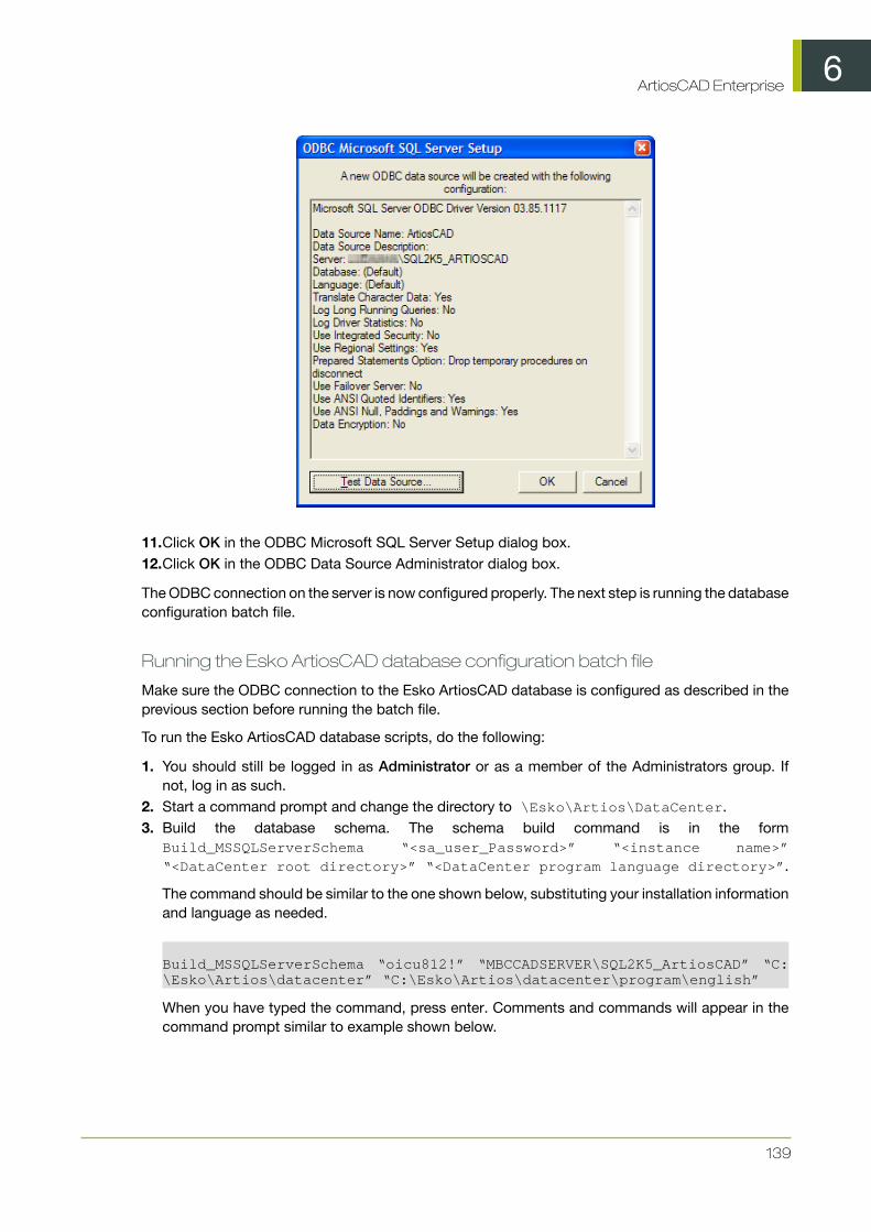
6ArtiosCAD Enterprise
139
11.Click OK in the ODBC Microsoft SQL Server Setup dialog box.12.Click OK in the ODBC Data Source Administrator dialog box.
The ODBC connection on the server is now configured properly. The next step is running the databaseconfiguration batch file.
Running the Esko ArtiosCAD database configuration batch file
Make sure the ODBC connection to the Esko ArtiosCAD database is configured as described in theprevious section before running the batch file.
To run the Esko ArtiosCAD database scripts, do the following:
1. You should still be logged in as Administrator or as a member of the Administrators group. Ifnot, log in as such.
2. Start a command prompt and change the directory to \Esko\Artios\DataCenter.3. Build the database schema. The schema build command is in the form
Build_MSSQLServerSchema “<sa_user_Password>” “<instance name>”“<DataCenter root directory>” “<DataCenter program language directory>”.
The command should be similar to the one shown below, substituting your installation informationand language as needed.
Build_MSSQLServerSchema “oicu812!” “MBCCADSERVER\SQL2K5_ArtiosCAD” “C:\Esko\Artios\datacenter” “C:\Esko\Artios\datacenter\program\english”
When you have typed the command, press enter. Comments and commands will appear in thecommand prompt similar to example shown below.

6ArtiosCAD Enterprise
140
4. When the command prompt returns, type exit and press enter.
The database is now ready for use with Esko ArtiosCAD and DataCenter Admin. Add servers andresources as described in the Working with servers and resources section of the DataCenter chapterof the Esko ArtiosCAD User Guide.
Notes and troubleshooting
Microsoft Data Access Components (MDAC) version 2.8 or higher must be used with Microsoft SQLServer 2005.
The following notes deal with using SQL Server Management Studio in the Microsoft SQL Serverfolder on the Start menu.
• If error messages appear about not being associated with a trusted SQL Server connection, right-click the server instance name, and then click Properties > Security. Make sure SQL Server andWindows Authentication mode is selected in the Server authentication group.
• If many script errors appear, make sure the Implicit transactions checkbox is clear on theProperties > Connections page in the Default connection options list.
• If error messages appear about the programmer user not existing or not having permission, dothe following:
• Expand the database instance in the left pane so the Security folder is open and double-clickLogins.
• Right-click Programmer and click Properties.• On the General page, there should be a password set in the Password: field, the Default
database: should be set to ArtiosCADdb, and the Default language: should be set to English.If this is not so, click the Server Roles page and ensure that public is checked.

6ArtiosCAD Enterprise
141
If you are using SQL Server 2005 Express Edition and you need to run the database script batch file,use Build_ExpressSchema.bat with the same syntax as Build_MSSQLServerSchema.bat.
Using Oracle
Instruction on installing Oracle is beyond the scope of this document. It should only be done byexperienced database administrators. Here is a rough overview of the steps required:
• Install Oracle and create an instance. Within that instance create a database. Set up networkaccess to it using Net Configuration Assistant to connect to that database.
• Install Esko ArtiosCAD on the database server, making sure to do an Advanced installation andselecting Microsoft SQL Server 2000 or Oracle as the database choice.
• Set up an ODBC Data Source using the Microsoft ODBC for Oracle driver. Set theData Source Name: to ArtiosCAD, the Description: to ArtiosCAD, and the Server: toTNS:Name_of_database_defined_in_Net_Config-uration_Assistant that you configured wheninstalling Oracle, such as TNS:orcl.
• Run the database configuration batch file to build the database schema.
Start a command prompt and change the directory to \Esko\Artios\DataCenter.
The schema build command is in the form Build_OracleSchema “<sys Password>”“<TNS name>” “<DataCenter root directory>” “<DataCenter program languagedirectory>”.
If the sys database user has no password, use a double set of quotation marks (“”).
The final command you type at the command prompt should be similar to the one shown below,substituting your installation information and language as needed.
Build_OracleSchema “administrator” “orcl” “C:\Artios\datacenter” “C:\Artios\datacenter\program\english”
• Add servers and resources as described in the Working with servers and resources section ofthe DataCenter chapter of the Esko ArtiosCAD User Guide.
Note: If WebCenter and your production installation of Esko ArtiosCAD (not the one requiredfor WebCenter’s Application server) are using the same database server with Oracle 9i, and youupgrade the version of Oracle on the database server, it may break the Microsoft ODBC for Oracledrivers required by Esko ArtiosCAD. Please note that this is NOT a supported configuration andyou alone are responsible for ensuring that it works. If you upgrade Oracle and start gettingSQLSetConnectAttr errors, try changing two entries in the Registry on the database server.Specifically, in HKEY_LOCAL_MACHINE > Software > Microsoft > MsDTC > MTxOCI, change theOracleSqlLib key to orasql9.dll and change the OracleXaLib key to oraclient9.dll.
Replacing an Esko ArtiosCAD server
As time passes, you may need to replace an existing Esko ArtiosCAD server with a newer, fastermodel. Listed below are the basic steps required to replace a machine acting as the Defaults server,
6ArtiosCAD Enterprise
142
Database server using MSDE, and License server using a security key. Contact Esko Support formore details.
1. Make a complete backup of the system that is being replaced and verify that the data is readable.Keep this backup in safe, easily-accessible place.
2. Install the same version of Esko ArtiosCAD on the new server as is currently on the existing server.Make sure to specify the same licensing method.
3. Copy the ..\Esko\Artios\ArtiosCADn.nnll\ServerLib folder from the existing server to the newserver.
4. Copy ..\Esko\Artios\ArtiosCADn.nnll\Common\tuneopt.txt and/or tuneopt7.txt on the old serverto the corresponding directory on the new server.
5. Move the security key to the new server.6. Start Esko ArtiosCAD on the new server and click Options > Defaults.7. Go through the various entries and adjust them as necessary, specifically the entries for Output
devices and other things which may contain system names or paths.8. An exact image copy of the database from the old server will be made on the new server.
Therefore, put the user files (if any) in the same location in the file system on the new machineas on the old machine.
9. On the old system, detach the database using the following procedure:
• Log in as a member of the Administrators group.• Start a command prompt.• At the prompt, type osql -Usa -P”” -Ssystemname\ArtiosCADdb and press enter. (If the sa
password is not blank, insert it between the quotation marks in the -P switch.)• At the 1> prompt, type sp_detach_db ‘ArtiosCADdb’ and press enter.• At the 2> prompt, type go and press enter.• At the 1> prompt, type quit and press enter.• Type exit and press enter to close the command prompt.
10.On the new server, do the same thing to detach the empty, just-installed MSDE database:
• Log in as a member of the Administrators group.• Start a command prompt.• At the prompt, type osql -Usa -P”” -Ssystemname\ArtiosCADdb and press enter. (If the sa
password is not blank, insert it between the quotation marks in the -P switch.)• At the 1> prompt, type sp_detach_db ‘ArtiosCADdb’ and press enter.• At the 2> prompt, type go and press enter.• Do not close this program as it is needed for a future step.
11.Copy the database files from the old server to the new server. They are in the ..\Esko\Artios\DataCenter\MSDE\MSSQL$ARTIOSCADDB\Data directory. Copy ArtiosCADdb_data.mdf andArtiosCADdb_log.ldf to the corresponding directory on the new server. If prompted to overwriteexisting files, say yes.
12.On the new server, attach the new database files to the instance:
• In the command prompt window running osql, at the 1> prompt,type sp_attach_db “ArtiosCADdb”, “C:\Esko\Artios\DataCenter\MSDE\MSSQL$ARTIOSCADDB\Data\ArtiosCADdb.mdf” and press enter. Note: Do not omit the comma.Also, change the path to the .mdf file as needed if you did not install Esko ArtiosCAD to theC: drive.
• At the 2> prompt, type go and press enter.

6ArtiosCAD Enterprise
143
13.Reconnect the programmer database login to the database instance:
• At the 1> prompt, type use ArtiosCADdb and press enter.• At the 2> prompt, type go and press enter.• At the 1> prompt, type sp_change_users_login update_one, programmer, programmer, null
and press enter.• At the 2> prompt, type go and press enter.• At the 1> prompt, type quit and press enter.• Type exit and press enter to close the command prompt.
14.In DataCenter Admin, go through the entries for servers and resources and adjust them asnecessary.
15.If the old server used ArtiosIO, configure and start it on the new server.16.On each client, use Add/Remove Programs in Control Panel to Change and then Modify the
installation of Esko ArtiosCAD. Specify the name of the server as appropriate.
Esko ArtiosCAD should now be fully functional on the new server and any clients.

7ArtiosCAD Enterprise
144
7. Defaults
Introduction to Defaults
Defaults store all the configuration information used by Esko ArtiosCAD. This is where you changeoptions, add custom standards to the Standards Catalog, define Outputs, and so forth. You accessdefaults by clicking Defaults on the Options menu. There are many options in Defaults that are notcovered in this chapter; you should open each Defaults catalog or folder and review its contents.
There are two types of defaults: Shared defaultsand User defaults. Shared defaults are shared by allusers served by the same Esko ArtiosCAD server. User defaults affect only the machine being used.
Creating defaults
There are three ways to create new defaults:
1. In the Shared defaults pane, open the folder containing the Defaults you want to add to and right-click. Clicking Folder adds a new folder; clicking Data adds a new default setting.
2. In the User defaults pane, make sure nothing is selected, and right-click. Choose the type ofdefault to add from the pop-up context menu. When naming the new item, do not use a backslash(\).
3. Drag a pre-existing default from one pane into the other and modify as desired.
7ArtiosCAD Enterprise
145
Changing defaults
To change a default, open the folder it is in and double-click it. A dialog box will appear showing allthe settings you can change.
If you want to change all the defaults in a folder at once, double-click the folder instead of an individualitem, and a tabbed dialog box will appear containing all the individual items.
Saving defaults
It is very important to save the defaults after you make changes. The option button above the twopanes indicates which set of defaults is being affected by the commands on the File menu. Makesure the option button is set to the pane of defaults you have changed, click File, and then click Save.
Defaults performance
ArtiosCAD loads Defaults into system memory when you launch it for more robust performance.
If you make changes to Defaults, click Options > Clear Defaults Cache to re-read Defaults intomemory without having to restart ArtiosCAD.
ArtiosCAD re-reads the Defaults automatically when you click Options > Defaults, so you onlyneed to clear the cache when you make a change and exit Defaults and then continue working inArtiosCAD. Another time to clear the cache would be when you changed Defaults on one computerand other users were sharing those Defaults on other computers and did not want to restartArtiosCAD; they would have to click Clear Defaults Cache to see your changes.
Parameter sets
Designer parameter sets
Parameter sets are collections of settings that govern how you work with designs or manufacturingfiles. The collection can be based on anything – by customers, by machines, or however else youwant to group information.
Single design parameter sets allow you to assign different values to different sets for the followingentries:
• Default bridging formulae to use• Flute/grain setting• Side up

7ArtiosCAD Enterprise
146
You select a parameter set when creating a design. You can change the parameter set being usedby a design by clicking Change Parameter Set on the Options menu.
To create a parameter set, do the following:
1. Start Esko ArtiosCAD.2. Click Options, and then click Defaults.3. To add a parameter set to Shared Defaults, open the Single Design Parameter Set entry. Right
click it, select New, and then click Data.4. Enter the name of this new parameter set and press Enter.5. Click the plus sign (+) next to the parameter set you created.6. Double-click Startup defaults. This will bring up a tabbed dialog box where you can set the initial
side of the design, a default flute/grain direction, and default bridging formulae.7. Click OK when you are done setting options for this new parameter set.8. Click File, and then click Save to save the changes.
Manufacturing parameter sets
Manufacturing parameter sets, in conjunction with machine parameter sets, allow you to customizevarious settings per set or per machine. A partial list of the values you can set are:
• Die board size• Automatic stripping parameters• Default bridging formulae• Hole mounting pattern workspaces and the side of the die used to determine if they are mirrored
or not• The Machine Reference Point, used by many things for alignment• Settings for scrap/chop knives• Mounting alignment hole parameters
A manufacturing parameter set references a die press parameter set and a printing press parameterset in addition to containing its own values.
To create a die press or printing press parameter set, do the following:
1. Start Esko ArtiosCAD.2. Click Options, and then click Defaults.3. To add a parameter set to Shared Defaults, open the Die Press Parameter Sets or Printing Press
Parameter Sets entry. Right click it, select New, and then click Data.4. Enter the name of this new parameter set and press Enter.5. Click the plus sign (+) next to the parameter set you created. The parameter set expands to show
the top-level categories. Click each plus sign to open each category.
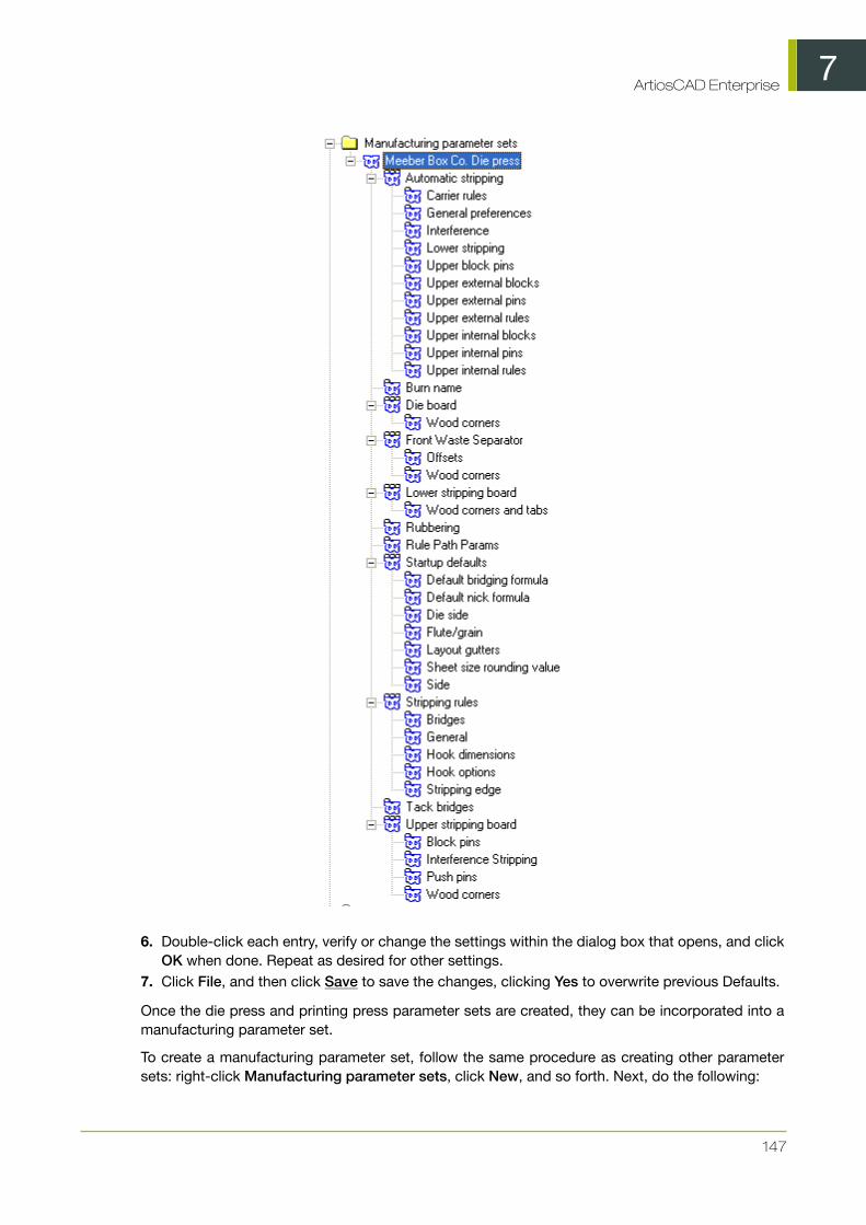
7ArtiosCAD Enterprise
147
6. Double-click each entry, verify or change the settings within the dialog box that opens, and clickOK when done. Repeat as desired for other settings.
7. Click File, and then click Save to save the changes, clicking Yes to overwrite previous Defaults.
Once the die press and printing press parameter sets are created, they can be incorporated into amanufacturing parameter set.
To create a manufacturing parameter set, follow the same procedure as creating other parametersets: right-click Manufacturing parameter sets, click New, and so forth. Next, do the following:
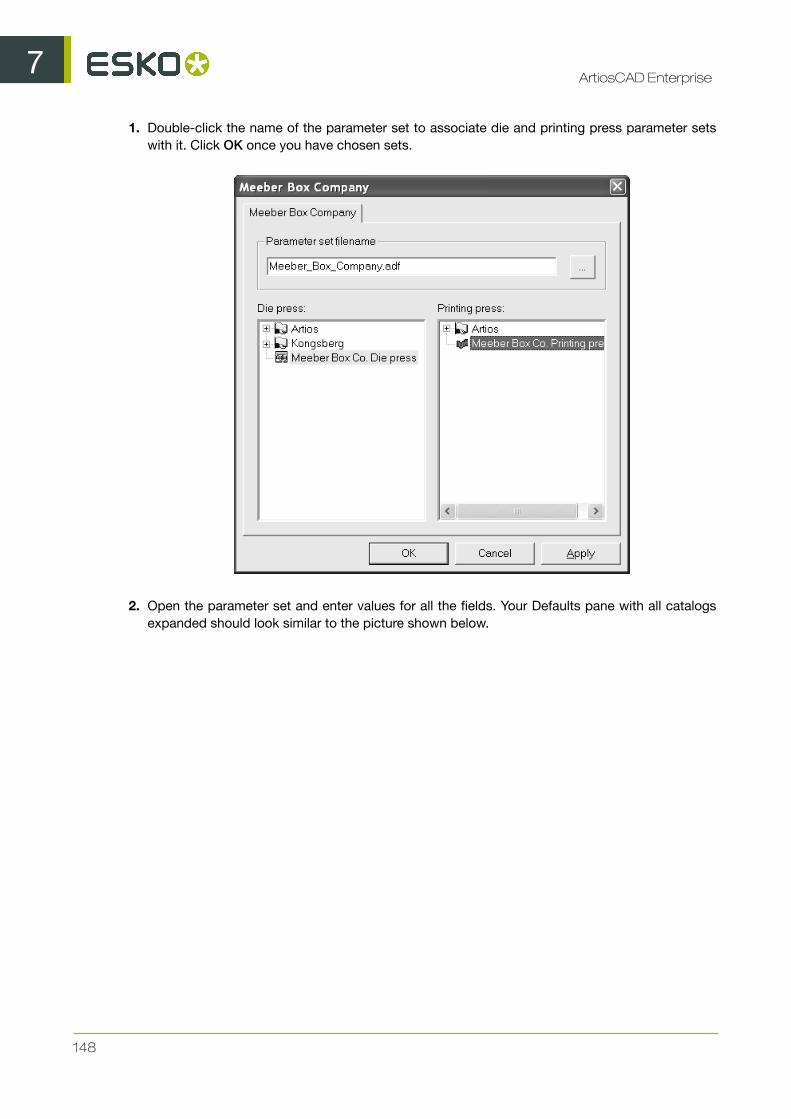
7ArtiosCAD Enterprise
148
1. Double-click the name of the parameter set to associate die and printing press parameter setswith it. Click OK once you have chosen sets.
2. Open the parameter set and enter values for all the fields. Your Defaults pane with all catalogsexpanded should look similar to the picture shown below.
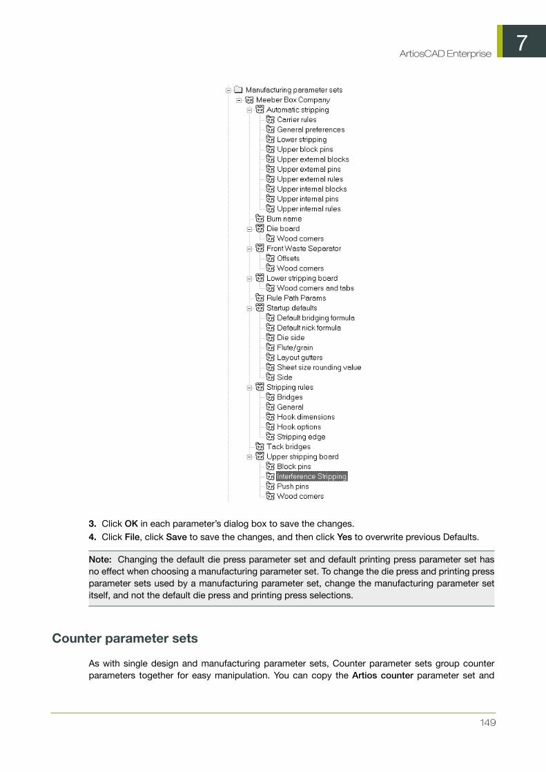
7ArtiosCAD Enterprise
149
3. Click OK in each parameter’s dialog box to save the changes.4. Click File, click Save to save the changes, and then click Yes to overwrite previous Defaults.
Note: Changing the default die press parameter set and default printing press parameter set hasno effect when choosing a manufacturing parameter set. To change the die press and printing pressparameter sets used by a manufacturing parameter set, change the manufacturing parameter setitself, and not the default die press and printing press selections.
Counter parameter sets
As with single design and manufacturing parameter sets, Counter parameter sets group counterparameters together for easy manipulation. You can copy the Artios counter parameter set and

7ArtiosCAD Enterprise
150
modify it to meet your unique needs, or you can create a new parameter set by right-clicking andselecting New on the context menu.
Double-click a parameter set to open it for editing.
Tool Angles, Widths tab
Shown below is Tool Angles, Width tab of the Artios counter parameter set.
Fields followed by f(x) indicate that the parameter being set is dependent on the board. Clicking f(x)leads to the Edit Expression dialog box, where the following parameters should be used to buildexpressions:
#CWIDTHWG Width of with grain creases
#CWIDTHXG Width of cross grain creases
CAL Board caliper
The five parameters in this dialog box are configured like this:
Description WorkspaceVariable
Default Expression Notes
Counter thickness CHGT ROUNDUP(CAL+0.007*#I,0.002*#i)
Affects the peripheryand chamfer tooloffset.

7ArtiosCAD Enterprise
151
Description WorkspaceVariable
Default Expression Notes
Crease channeldepth
CRECHD CAL+0.002*#I For information only.Does not affect toolpaths.
Chamfer depth CHAMFD CHGT-0.004*#I Automatically limitedby maximum chamferwidth.
With grain channelwidth
CHWWG #CWIDTHWG+2*CAL
Cross grain channelwidth
CHWXG #CWIDTHXG+2*CAL+0.004*#I
The Maximum Chamfer Diameter is usually the diameter of the chamfer tool head.
Periphery tab
The Periphery tab of the counter parameter set dialog box contains settings which affect theperiphery tool.
The parameters on this page of the dialog box are all measurements whose functions are illustratedin the pictures next to them except for the Periphery Tool Angle. The angle specified in the PeripheryTool Angle field, along with the thickness of the counter material, determines the width of theperiphery.
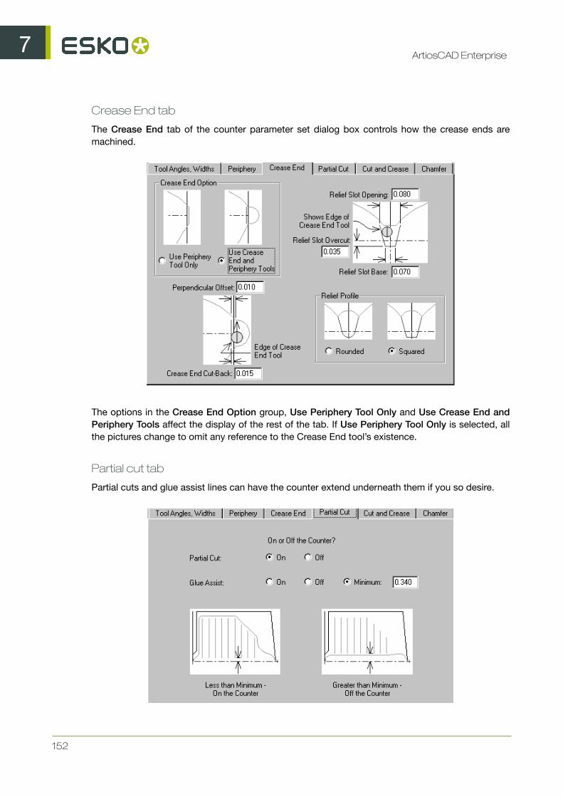
7ArtiosCAD Enterprise
152
Crease End tab
The Crease End tab of the counter parameter set dialog box controls how the crease ends aremachined.
The options in the Crease End Option group, Use Periphery Tool Only and Use Crease End andPeriphery Tools affect the display of the rest of the tab. If Use Periphery Tool Only is selected, allthe pictures change to omit any reference to the Crease End tool’s existence.
Partial cut tab
Partial cuts and glue assist lines can have the counter extend underneath them if you so desire.
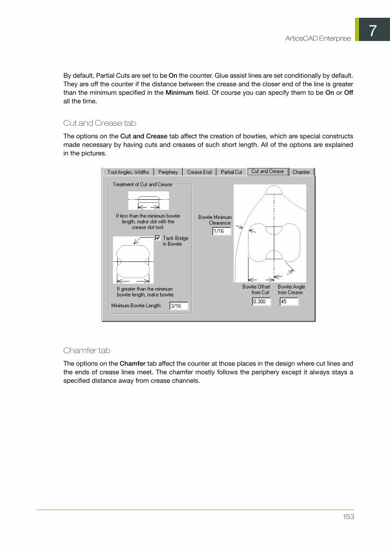
7ArtiosCAD Enterprise
153
By default, Partial Cuts are set to be On the counter. Glue assist lines are set conditionally by default.They are off the counter if the distance between the crease and the closer end of the line is greaterthan the minimum specified in the Minimum field. Of course you can specify them to be On or Offall the time.
Cut and Crease tab
The options on the Cut and Crease tab affect the creation of bowties, which are special constructsmade necessary by having cuts and creases of such short length. All of the options are explainedin the pictures.
Chamfer tab
The options on the Chamfer tab affect the counter at those places in the design where cut lines andthe ends of crease lines meet. The chamfer mostly follows the periphery except it always stays aspecified distance away from crease channels.

7ArtiosCAD Enterprise
154
The Chamfer Gap is the distance between the inside edge of a chamfer and the crease channel.The Pickup and No Pickup options control whether the chamfer is continuous around the end of thecrease channel. The Chamfer Tool Angle is the angle of the tool, which, together with the thicknessof the counter material, determines the width of the chamfer channel.
Reverse Creases tab
Reverse creases are used to make a panel fold outward instead of inward.
The Insert option indicates that a piece of foreign material will be attached to the counter to createthe reverse crease. This is shown in the top picture on the tab. Counter material means that an areaaround the reverse crease will be milled out so that the board gets pushed into the depressed area.This is shown in the bottom picture on the tab. The Crease Width field becomes available when thisoption is selected. Off the counter disables all the fields.

7ArtiosCAD Enterprise
155
Reverse Cuts tab
Reverse cuts are made on the counter in the same way as the Insert method for reverse creases.The parameters on the Reverse Cuts tab are explained in the picture.
Embossing tab
An area of the board can be embossed by milling out the part of the counter surrounding theembossed area. As with other tabs, the parameters on the Embossing tab are explained in thepicture.
Position Holes tab
The Position Holes tab contains one parameter - the workspace name for the position hole. ClickSpecify to browse for a new workspace.
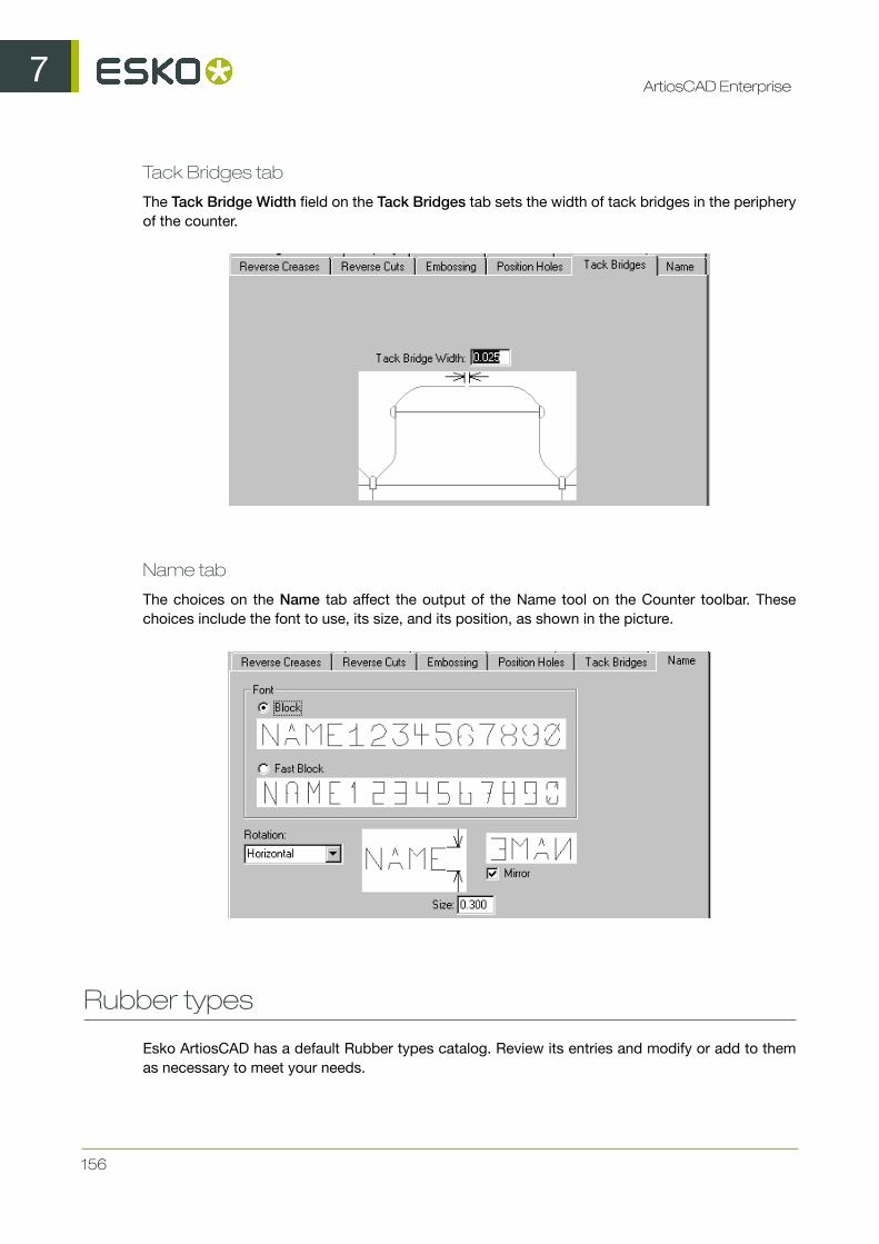
7ArtiosCAD Enterprise
156
Tack Bridges tab
The Tack Bridge Width field on the Tack Bridges tab sets the width of tack bridges in the peripheryof the counter.
Name tab
The choices on the Name tab affect the output of the Name tool on the Counter toolbar. Thesechoices include the font to use, its size, and its position, as shown in the picture.
Rubber types
Esko ArtiosCAD has a default Rubber types catalog. Review its entries and modify or add to themas necessary to meet your needs.

7ArtiosCAD Enterprise
157
A rubber type is defined by its unique name, thickness, and stock sheet size. If there are rubbertypes defined that are different thicknesses of the same material, include the thickness in the name,as each name must be unique.
To edit a rubber type, double-click its name. To create a new rubber type, right-click the Rubbertypes catalog and click New > Data on the context menu.
Shown below are the properties for the Red Neoprene rubber type.
Reversible indicates if the top and bottom sides of the rubber are the same, so that a piece of rubberand its mirror image could be considered the same when making layouts. (This is different from themirror options in Auto-Repeat.)
The value in the Rubber code: field is what is used on the Sheet Filename Generation page of therubber sheets Output. Use letter and numbers only with no spaces.
Set the Sheet width: and Sheet height: fields to the appropriate sizes of the sheets for this typeof rubber.
The Thickness: field is currently unused, but to prepare for its possible use in the future, enter thethickness of the sheet.
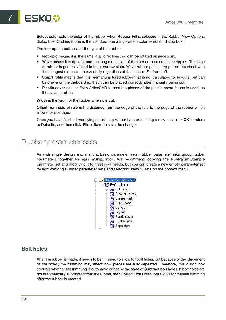
7ArtiosCAD Enterprise
158
Select color sets the color of the rubber when Rubber Fill is selected in the Rubber View Optionsdialog box. Clicking it opens the standard operating system color selection dialog box.
The four option buttons set the type of the rubber.
• Isotropic means it is the same in all directions, so can be rotated as necessary.• Wave means it is rippled, and the long dimension of the rubber must cross the ripples. This type
of rubber is generally used in long, narrow slots. Wave rubber pieces are put on the sheet withtheir longest dimension horizontally regardless of the state of Fill from left.
• Strip/Profile means that it is premanufactured rubber that is not calculated for layouts, but canbe drawn on the dieboard so that it can be placed correctly after manually being cut.
• Plastic cover causes Esko ArtiosCAD to nest the pieces of the plastic cover (if one is used) asif they were rubber.
Width is the width of the rubber when it is cut.
Offset from side of rule is the distance from the edge of the rule to the edge of the rubber whichallows for pointage.
Once you have finished modifying an existing rubber type or creating a new one, click OK to returnto Defaults, and then click File > Save to save the changes.
Rubber parameter sets
As with single design and manufacturing parameter sets, rubber parameter sets group rubberparameters together for easy manipulation. We recommend copying the RubParamExampleparameter set and modifying it to meet your needs, but you can create a new empty parameter setby right-clicking Rubber parameter sets and selecting New > Data on the context menu.
Bolt holes
After the rubber is made, it needs to be trimmed to allow for bolt holes, but because of the placementof the holes, the trimming may affect how pieces are auto-repeated. Therefore, this dialog boxcontrols whether the trimming is automatic or not by the state of Subtract bolt holes. If bolt holes arenot automatically subtracted from the rubber, the Subtract Bolt Holes tool allows for manual trimmingafter the rubber is created.
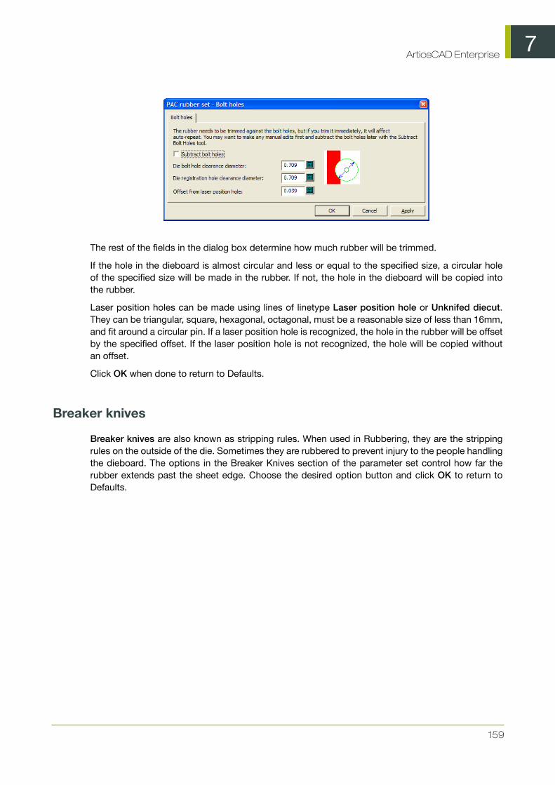
7ArtiosCAD Enterprise
159
The rest of the fields in the dialog box determine how much rubber will be trimmed.
If the hole in the dieboard is almost circular and less or equal to the specified size, a circular holeof the specified size will be made in the rubber. If not, the hole in the dieboard will be copied intothe rubber.
Laser position holes can be made using lines of linetype Laser position hole or Unknifed diecut.They can be triangular, square, hexagonal, octagonal, must be a reasonable size of less than 16mm,and fit around a circular pin. If a laser position hole is recognized, the hole in the rubber will be offsetby the specified offset. If the laser position hole is not recognized, the hole will be copied withoutan offset.
Click OK when done to return to Defaults.
Breaker knives
Breaker knives are also known as stripping rules. When used in Rubbering, they are the strippingrules on the outside of the die. Sometimes they are rubbered to prevent injury to the people handlingthe dieboard. The options in the Breaker Knives section of the parameter set control how far therubber extends past the sheet edge. Choose the desired option button and click OK to return toDefaults.

7ArtiosCAD Enterprise
160
Crease Mask
The options in the Crease Mask section of the parameter set control how the rubber is cut backnear creases.

7ArtiosCAD Enterprise
161
The options in this dialog box are made available or unavailable by the state of Make Plastic Coverin the General section of the parameter set. When that option is not selected, the controls in thebottom half of this dialog box are unavailable, and when it is selected, the controls in the top halfare unavailable.
For normal areas of the design, the options along the left side of the top quarter of the dialog boxare the distance that is cut back from the crease, and the values on the right side are the angles atwhich the cuts are made. Each end of the cutback is the same as it is symmetrical.
For thin areas of the design, the rubber pieces are smaller so there are fewer cutbacks.
When a plastic cover is used, set the offsets from the plastic cover edge and from the edge of thecrease rule as desired.
Click OK when done to return to Defaults.
Cut/Crease
Esko ArtiosCAD can treat cut/crease rules as if they were cuts, or creases, or a mixture of the two.They need to have different parameters than the standard crease mask so that the angle of thecutbacks can be greater, so these are set in the Cut/Crease section of the parameter set. Also, rubberpieces for cut/crease rule are made thicker (to the thickness you specify in this dialog box) so theydo not break at the thin points.
In the Treat cut/crease group, Like cuts, Like creases, and Use parameters below all behave as theirnames imply. Use parameters below enables the distance and angle fields for the crease cutback.
Click OK when done to return to Defaults.
General
The General section of the parameter set contains settings that affect the overall creation of therubber.
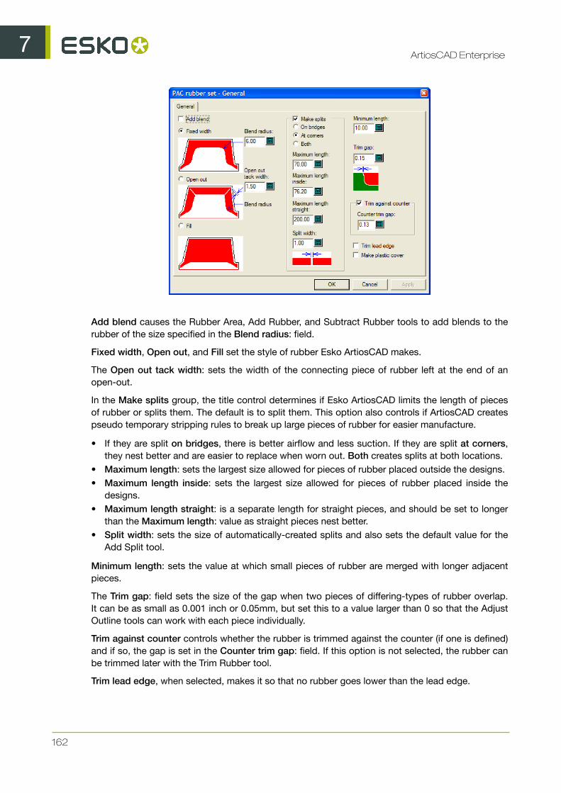
7ArtiosCAD Enterprise
162
Add blend causes the Rubber Area, Add Rubber, and Subtract Rubber tools to add blends to therubber of the size specified in the Blend radius: field.
Fixed width, Open out, and Fill set the style of rubber Esko ArtiosCAD makes.
The Open out tack width: sets the width of the connecting piece of rubber left at the end of anopen-out.
In the Make splits group, the title control determines if Esko ArtiosCAD limits the length of piecesof rubber or splits them. The default is to split them. This option also controls if ArtiosCAD createspseudo temporary stripping rules to break up large pieces of rubber for easier manufacture.
• If they are split on bridges, there is better airflow and less suction. If they are split at corners,they nest better and are easier to replace when worn out. Both creates splits at both locations.
• Maximum length: sets the largest size allowed for pieces of rubber placed outside the designs.• Maximum length inside: sets the largest size allowed for pieces of rubber placed inside the
designs.• Maximum length straight: is a separate length for straight pieces, and should be set to longer
than the Maximum length: value as straight pieces nest better.• Split width: sets the size of automatically-created splits and also sets the default value for the
Add Split tool.
Minimum length: sets the value at which small pieces of rubber are merged with longer adjacentpieces.
The Trim gap: field sets the size of the gap when two pieces of differing-types of rubber overlap.It can be as small as 0.001 inch or 0.05mm, but set this to a value larger than 0 so that the AdjustOutline tools can work with each piece individually.
Trim against counter controls whether the rubber is trimmed against the counter (if one is defined)and if so, the gap is set in the Counter trim gap: field. If this option is not selected, the rubber canbe trimmed later with the Trim Rubber tool.
Trim lead edge, when selected, makes it so that no rubber goes lower than the lead edge.

7ArtiosCAD Enterprise
163
Make plastic cover, when selected, causes a plastic cover to be made in its own layer when theRubber Area tool is used.
Click OK when done to return to Defaults.
Layout
If you have the Rubber Design and Layout option, Esko ArtiosCAD can automatically group piecesof rubber on the sheets based on their shapes.
Trim is the distance from the edge of the rubber sheet to the edges of the rubber elements, andGutter is the distance between each rubber element.
Increasing the value in the Nesting tries: field causes Esko ArtiosCAD to try more nests, but thistakes more time.
The five choices in the Grouping group control how the instances of each rubber element are groupedtogether on the sheets. Manual means that the grouping will be taken from the values set in the ListRubber Elements dialog box. None means that each item will be considered its own group. Lowmeans only straight items will be grouped together. Medium will do an intermediate level of grouping,but High will group together as many instances of the element as possible. These controls are meantto let you find the balance between making pieces easy to find and wasting the least rubber.
Click OK when done to return to Defaults.
Plastic cover
Some diemakers glue a plastic cover on top of the pieces of rubber to keep the board from stickingto the rubber as the press operates. The plastic cover pieces are supported by pieces of rubberon all sides, including along creases. The plastic cover extends slightly past the pieces of rubberunderneath. Plastic cover pieces are not generated for slots.
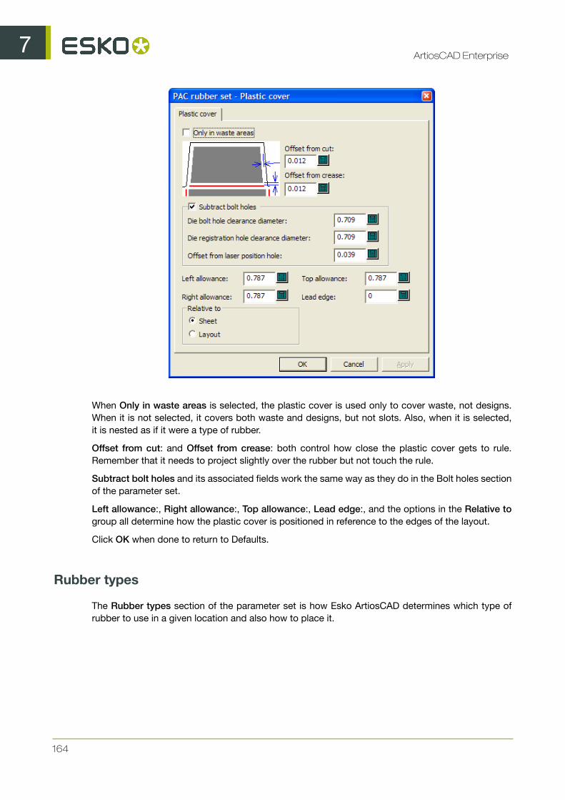
7ArtiosCAD Enterprise
164
When Only in waste areas is selected, the plastic cover is used only to cover waste, not designs.When it is not selected, it covers both waste and designs, but not slots. Also, when it is selected,it is nested as if it were a type of rubber.
Offset from cut: and Offset from crease: both control how close the plastic cover gets to rule.Remember that it needs to project slightly over the rubber but not touch the rule.
Subtract bolt holes and its associated fields work the same way as they do in the Bolt holes sectionof the parameter set.
Left allowance:, Right allowance:, Top allowance:, Lead edge:, and the options in the Relative togroup all determine how the plastic cover is positioned in reference to the edges of the layout.
Click OK when done to return to Defaults.
Rubber types
The Rubber types section of the parameter set is how Esko ArtiosCAD determines which type ofrubber to use in a given location and also how to place it.
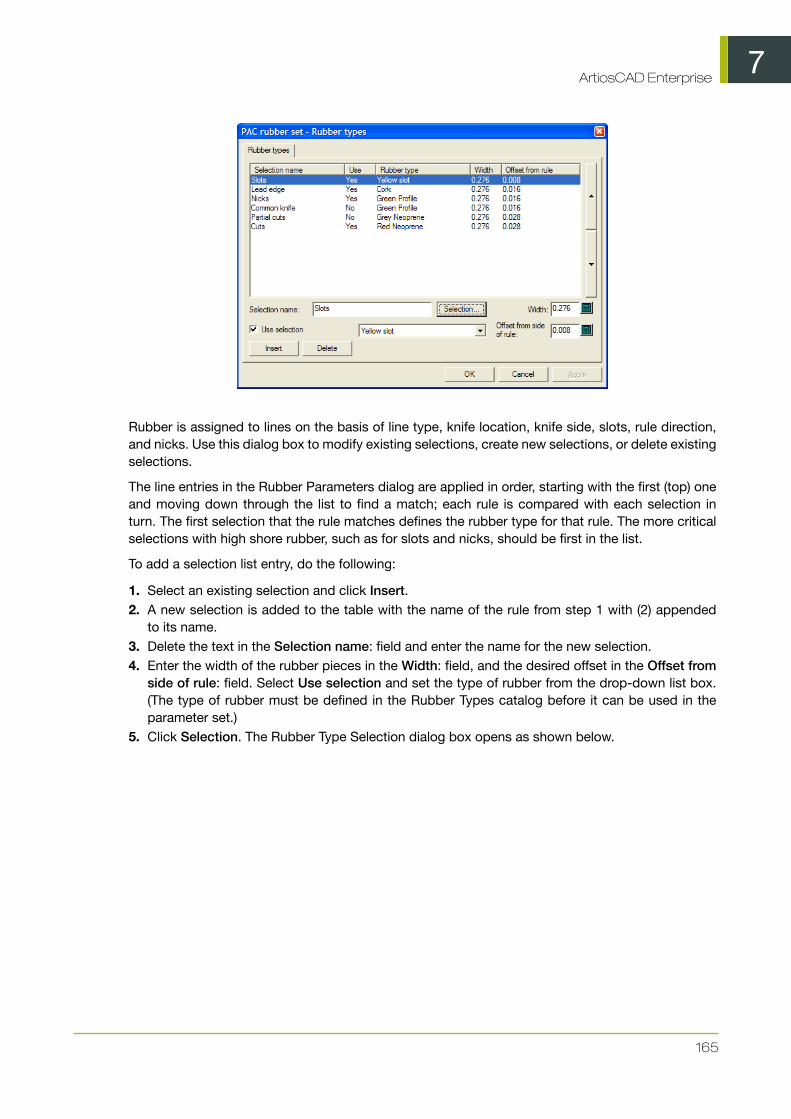
7ArtiosCAD Enterprise
165
Rubber is assigned to lines on the basis of line type, knife location, knife side, slots, rule direction,and nicks. Use this dialog box to modify existing selections, create new selections, or delete existingselections.
The line entries in the Rubber Parameters dialog are applied in order, starting with the first (top) oneand moving down through the list to find a match; each rule is compared with each selection inturn. The first selection that the rule matches defines the rubber type for that rule. The more criticalselections with high shore rubber, such as for slots and nicks, should be first in the list.
To add a selection list entry, do the following:
1. Select an existing selection and click Insert.2. A new selection is added to the table with the name of the rule from step 1 with (2) appended
to its name.3. Delete the text in the Selection name: field and enter the name for the new selection.4. Enter the width of the rubber pieces in the Width: field, and the desired offset in the Offset from
side of rule: field. Select Use selection and set the type of rubber from the drop-down list box.(The type of rubber must be defined in the Rubber Types catalog before it can be used in theparameter set.)
5. Click Selection. The Rubber Type Selection dialog box opens as shown below.

7ArtiosCAD Enterprise
166
In this dialog box you select the conditions that a piece of rule must meet in order to be rubberedby the type of rubber selected. The checkboxes in the Line types: group and the Knife Location:group use OR logic, but the two groups together use AND logic: Cut/knife OR Stripping rule ORScrap knife OR Balance knife, and so forth, AND of type Leading edge knife OR Exterior waste ORInterior slit, and so forth.
If the type of rubber you are defining is for slots, select Slots and enter the maximum width of theslot in the Width limit: field. If you define more than one type of rubber for slots, the narrowest slotshould be highest in the list in the Rubber types dialog box, followed by the wider slots.
The other groups allow you to add more conditions to the rules that will receive this type of rubber;set them as desired. Nicks have the following restrictions: For Short piece centered on nick, theDistance past nick: field should be more than the width of the rubber. Also, for both of the first twooptions, the Minimum length should be less than the remaining length lines which you do not wantto have the nick rubber type.
For the Knife Location: group, refer to the picture and table below.

7ArtiosCAD Enterprise
167
Table: Knife locations for rubbering types
Number Location
1 Side
2 Trailing edge
3 Breaker knife (stripping rule)
4 Interior slit
5 Product side
6 Waste side
7 Common knife
8 Common waste
9 Interior waste
10 Leading edge
Once you have finished selecting the criteria for this rule, click OK to return to the Rubber Typesdialog box.
1. Use the arrows at the right end of the list to move the selected rubber type selection either upor down in the priority list.
2. Repeat the process as desired to add selection list entries.3. Click OK when done to return to Defaults.
All rule types except crease and balance knife should select a rubber type (rubber on balance knivesis optional because this does not interfere with rubber on other rules). If you want no rubber on aparticular rule type, because you are going to put rubber there manually, you should select rubbertype None for this rule type, and still define an offset and a width, so Esko ArtiosCAD knows howmuch space to leave for it.
For example, suppose you want no rubber on cut/crease. Copy the Cuts selection on the Rubbertypes tab, change the name to Cut/crease, change the rubber to None, and change the selection toselect Cut crease lines. You can adjust the width and offset from rule for the rubber you are goingto add manually.
If there are rules on the die with no rubber type defined, Esko ArtiosCAD displays a warning dialogwhen you start the Rubber Area tool. You can either show the rules with no rubber type defined, oryou can ignore the error, in which case surrounding rubber along nearby rules will cross the rulesfor which no rubber type is defined.
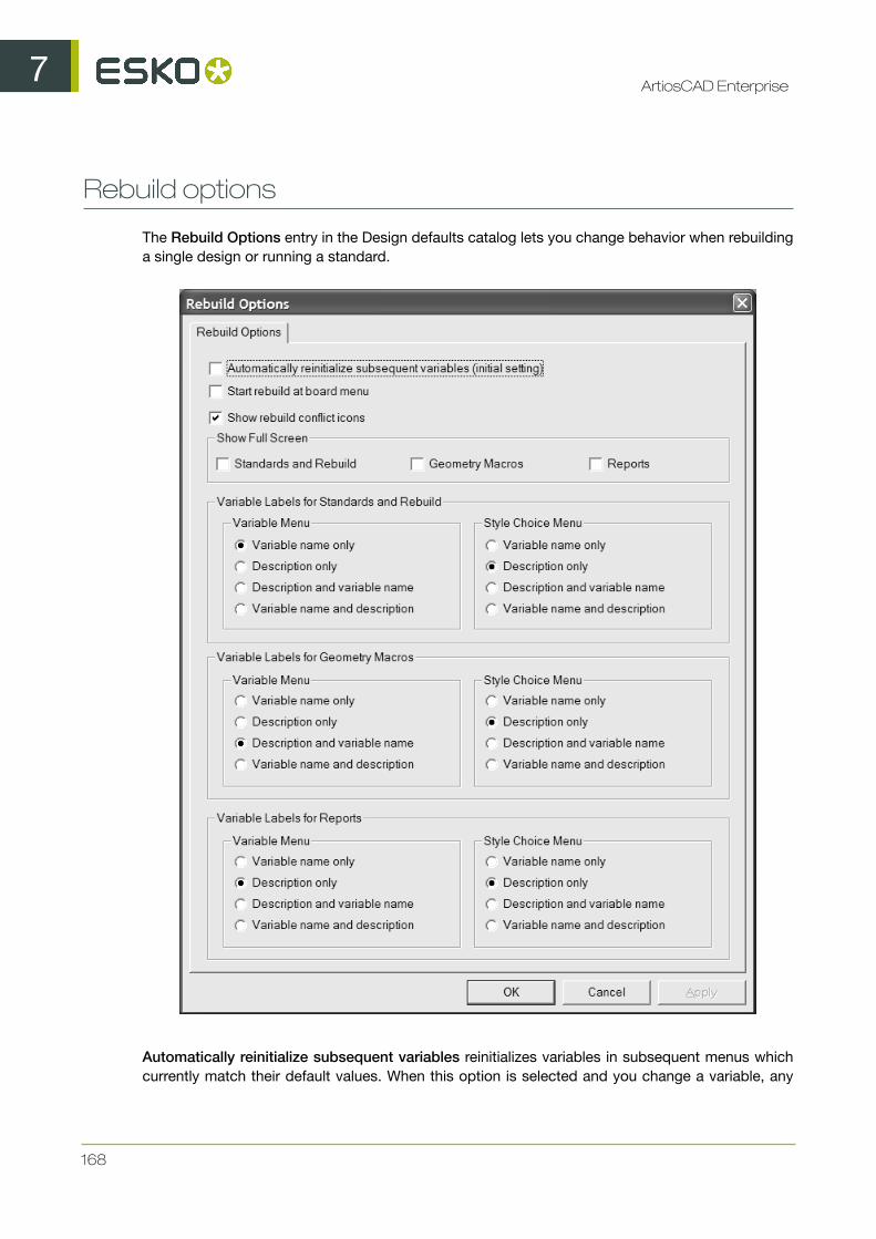
7ArtiosCAD Enterprise
168
Rebuild options
The Rebuild Options entry in the Design defaults catalog lets you change behavior when rebuildinga single design or running a standard.
Automatically reinitialize subsequent variables reinitializes variables in subsequent menus whichcurrently match their default values. When this option is selected and you change a variable, any

7ArtiosCAD Enterprise
169
subsequent variable depending on that variable which matched its default value before the rebuildstarted will get updated with the new value. For example, with this option selected, if you changeL, any variable in any subsequent menu which depends on L gets automatically updated with thenew value for L.
When this option is off, dependent variables are not automatically updated and are flagged for reviewin the Rebuild Conflicts dialog box
Start rebuild at board menu controls whether you may choose a new board when rebuilding a designinstead of starting at the first visible menu.
Show full screen sets the Rebuild, Run Standard, and Reports dialog boxes to the maximum sizepossible.
The options in the Variable labels... groups control what is shown to the left of the fields when runninga standard, rebuilding a design, using a geometry macro, or outputting a report. Choose from Variablename only, Description only, Description and variable name, and Variable name and description.If Description only is the chosen method and the variable description is blank, the variable name isused in parentheses. If there is no documentation plot for the menu, the description is shown withthe variable name in parentheses. These options can be changed on the fly in the dialog boxes byclicking the tiny triangle above the variable list and selecting a different display option.
Click OK to make the changes and return to Defaults, or click Cancel to discard the changes.
3D Import options
Use the options in Startup defaults > 3D Import to control how ArtiosCAD imports solids.
Render both sides shows the inside and the outside of the solid.
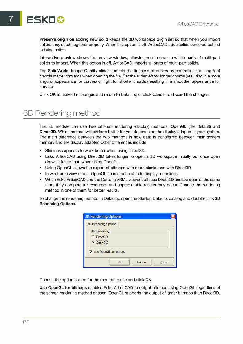
7ArtiosCAD Enterprise
170
Preserve origin on adding new solid keeps the 3D workspace origin set so that when you importsolids, they stitch together properly. When this option is off, ArtiosCAD adds solids centered behindexisting solids.
Interactive preview shows the preview window, allowing you to choose which parts of multi-partsolids to import. When this option is off, ArtiosCAD imports all parts of multi-part solids.
The SolidWorks Image Quality slider controls the fineness of curves by controlling the length ofchords made from arcs when opening the file. Set the slider left for longer chords (resulting in a moreangular appearance for curves) or right for shorter chords (resulting in a smoother appearance forcurves).
Click OK to make the changes and return to Defaults, or click Cancel to discard the changes.
3D Rendering method
The 3D module can use two different rendering (display) methods, OpenGL (the default) andDirect3D. Which method will perform better for you depends on the display adapter in your system.The main difference between the two methods is how data is transferred between main systemmemory and the display adapter. Other differences include:
• Shininess appears to work better when using Direct3D.• Esko ArtiosCAD using Direct3D takes longer to open a 3D workspace initially but once open
draws it faster than when using OpenGL.• Using OpenGL allows the export of bitmaps with more pixels than with Direct3D• In wireframe view mode, OpenGL seems to be able to display more lines.• When Esko ArtiosCAD and the Cortona VRML viewer both use Direct3D and are open at the same
time, they compete for resources and unpredictable results may occur. Change the renderingmethod in one of them for better results.
To change the rendering method in Defaults, open the Startup Defaults catalog and double-click 3DRendering Options.
Choose the option button for the method to use and click OK.
Use OpenGL for bitmaps enables Esko ArtiosCAD to output bitmaps using OpenGL regardless ofthe screen rendering method chosen. OpenGL supports the output of larger bitmaps than Direct3D.

7ArtiosCAD Enterprise
171
Save and exit Defaults as usual. The change is effective immediately. You can also change it at anytime by clicking Options > 3D Rendering Options.
Database defaults
Database defaults configure the operation of the Esko ArtiosCAD database. Click Options > Defaults,and in the Shared Defaults pane, click Design Defaults > Database to open the Database dialog box.
Enable Database, when checked, lets Esko ArtiosCAD save information to the database. When thecheckbox is clear, no new information is saved to the database. Database information that alreadyexists is retained.
Create Thumbnail in Format controls if Esko ArtiosCAD creates thumbnail pictures of workspaceswhen designs are saved. The thumbnails are stored in the database and are used by the databasebrowsers.
The drop-down list box next to the checkbox controls the type of thumbnail created.
BMP with RLE compression is the default choice. It creates thumbnails in BMP format using runlength encoding compression.
JPEG format creates thumbnails in JPG format, which is compressed but lossy (meaning some detailis lost).

7ArtiosCAD Enterprise
172
Folded JPEG format first tries to create a folded view for the thumbnail based on saved angles ina single design. If there are no saved angles, a flat thumbnail is created. In each case JPEG formatis used.
Artios3D format causes Esko ArtiosCAD to look for an .A3D file by the same name as the workspacebeing saved in the same directory, and if found, that is used for the thumbnail. If it is not found,Folded JPEG format is used instead.
File Operations group
The checkboxes in the File Operations group control database activity when creating or saving aworkspace.
Use Resource View on Open and Save As, when checked, directs Esko ArtiosCAD to use ResourceView when opening workspaces or saving them using Save As. Directory View is used when thisoption is not checked.
Show database dialog box when creating a new design, when checked, instructs Esko ArtiosCADto prompt you for database information when you create a new design.
Show Create As dialog box when creating a new design, when checked, when checked, instructsEsko ArtiosCAD to prompt you for the filename and resource or directory in which the design is tobe saved when creating a new design.
Show database dialog box when saving, when checked, tells Esko ArtiosCAD to prompt you fordatabase information when you save a workspace in a resource.
Synchronize disk file when saving in browsers, when checked, causes Esko ArtiosCAD to modifythe disk file for the record you change in a database browser. This is independent of saving therecord, which only affects the database.
Add new characteristics when synchronizing, when checked, instructs Esko ArtiosCAD to comparethe characteristics in a workspace being opened with those already in the database, and if there arenew ones in the file, prompts you to add them to the database.
Enable Skip DB button, when checked, lets you click Skip DB when saving a workspace so thatyou can save a workspace with no corresponding database information.
Performance options group
The checkboxes in the Performance Options group control how Esko ArtiosCAD retrieves certaintypes of information from the database.

7ArtiosCAD Enterprise
173
Typically, databases which run over WANs (Wide Area Networks), for example between plants,experience slower network performance compared to those which run over faster LANs (Local AreaNetworks). By default, Esko ArtiosCAD requests a complete set of database entities each time theDatabase Information dialog box is activated, which can lead to wait times if there are many recordsto download from the database server.
To address this, Esko ArtiosCAD can store the Customer, Owner, Designer, Salesperson,Characteristics, and User Fields entities from the Database Information dialog box in memory, aswell as the boards, companies, company types, and Resources. This is called caching.
Both Esko ArtiosCAD and CAD-X can use this feature, and each will use more memory if it is enabled.
Once the database dialog box entries or other entities are loaded into memory, Esko ArtiosCAD doesnot re-request them from the database. If changes are made to the entities in the database itself,Esko ArtiosCAD will not see them until the cache is refreshed or a new Esko ArtiosCAD session isstarted. To refresh the cache, click Database > Refresh cache > Item.
Esko ArtiosCAD can also search the database for specific records which match a pattern thusreturning only a few records instead of thousands. This feature is called pattern searching.
Note: These performance options do not apply to customized database information dialog boxes.To use them, you must use the standard database information dialog boxes.
Caching
Toggle the Cache dialog box entries checkbox to enable and disable caching.
The table below lists how the fields in the Database Information dialog box behave when databasedialog box entry caching is turned on. The Database Information dialog box behaves the same forSingle Design and Manufacturing.
Table: Dialog box behavior when database dialog entity caching is enabled
Field Behavior
Customer and Owner All Customer and Owner entities are requested when the dialog boxis first accessed, and then they are cached.
Salesperson and Designer All Salesperson and Designer entities are requested when the drop-down list box arrow for either field is first clicked, and then they arecached. They share the same cache.
Characteristics button Characteristics are requested the first time the button is clicked, andthen cached. Only applicable to Single Design.
User Fields button Same as Characteristics.

7ArtiosCAD Enterprise
174
Field Behavior
New button in Customerdialog box
Causes a refresh of the Customer cache.
In addition to caching Database Information dialog box entries, when caching is enabled, EskoArtiosCAD also caches boards, companies, company types, and Resources.
Once the database dialog box entries or other entities are loaded into memory, Esko ArtiosCAD doesnot re-request them from the database. If changes are made to the entities in the database itself,Esko ArtiosCAD will not see them until the cache is refreshed or a new Esko ArtiosCAD session isstarted. To refresh the cache, click Database > Refresh cache > Item.
Pattern searching
Another way to ensure robust database performance over a slow Wide Area Network for theCustomer, Owner, Designer, and Salesperson fields is to enable pattern searching by checking theUse pattern searching for customers and owners and Use pattern searching for designers andsalespeople checkboxes. To maintain compatibility with previous versions, these checkboxes areboth cleared by default.
When pattern searching is enabled, the Oneup Design Information and Manufacturing DatabaseInformation dialog boxes change. The drop-down list boxes for the Customer, Owner, Designer,and Salesperson fields disappear and the fields become disabled. In addition, there are ... buttonsleading to dialog boxes which let you search for records and then display details about the selectedrecords, or display details if there is already a selected record. Shown below is the Customer dialogbox; all four dialog boxes act similarly, but only the Customer dialog box has the New button.

7ArtiosCAD Enterprise
175
Pattern searching works by entering a few letters of a word, or a whole word, or a complete phrase,then choosing a method of searching, and then clicking Find. The results of the search populate thedrop-down list box.
Mixing database performance modes
Database dialog box entry caching and pattern searching can be used simultaneously, but not for allfour types of records. Only a pair of records (Customer and owners or designers and salespeople)for which pattern searching is turned off can be cached.
Database Information Dialog Customization groups
The options in the Single Design and Layout Database Information Dialog Customization groupsallow you to choose what happens when entering database information for a single design or layout.

7ArtiosCAD Enterprise
176
Use standard dialog uses the dialog box that is included with Esko ArtiosCAD.
Use custom dialog definition file enables the Customize button, which in turn leads to theControl Layout Manager described in the next section. Using this feature requires the InformationEnhancement option.
Use custom external application enables a field to specify the path to a custom program (such asan ERM program) that controls information storage instead of the Esko ArtiosCAD database. Thiscustom application is not provided or supported by Esko unless it was provided by the ProfessionalServices department. Using this feature requires the Information Enhancement option.
Designing a custom Database Information dialog box
When you choose Use custom dialog definition file and click Customize, the Control LayoutManager dialog box opens showing the current dialog box.
On the left is the dialog box itself showing the groups, labels, fields, and buttons. On the right arethe size controls, the control catalogs, the Properties fields for the selected item, and the OK, Test,Cancel, Open, and Save As buttons.
There is no undo functionality in the Control Layout Manager, but you can click Cancel to discardall changes and then start again.
To change the size of the dialog box, adjust the values in the Dialog Size: fields, or select the edgeof the dialog box within the definition window and drag it to the desired position. To make a dialogbox larger than the current one, resize the Control Layout Manager dialog box itself using standardWindows methods, and then increase the size of the dialog box window.
To add a control, select it from the catalog and drag it to the desired position. You may also double-click it; it will appear at the top left of the dialog box, and you may then select it and drag it to thedesired position.
To remove a control, select it and press Delete on the keyboard.

7ArtiosCAD Enterprise
177
To move a control, select it and drag it to the desired position, or select it and use the Position: fieldsin the Properties group to adjust its position. You can also select it and use the arrow keys to moveit in one-pixel increments.
To resize a control, select it, and use the handle points to change its size as desired, or select it anduse the Size: fields in the Properties group to adjust its size.
To change text in a control, select it, and then change the contents of the Text: field in the Propertiesgroup.
When editing a field in the Properties group, or a Dialog Size: field, click in another field or selecta different object to activate the changes made to the first object. Do not press enter as that isinterpreted as clicking OK and will thus close the dialog box.
Click OK to save the changes to the dialog box and close the Control Layout Manager. The singledesign information is saved as DBDlgDesignDef.xml, and the manufacturing data is saved asDBDlgMFGDef.xml, both in ServerLib or ClientLib depending on which set of defaults was changed.
Click Cancel to discard the changes to the dialog box and close the Control Layout Manager.
Click Test to open a sample dialog box that previews the final result.
Click Save As to save the dialog box layout to a file.
Click Open to open a previously-saved dialog box layout file.
Shown below is a modified Database group in the Control Layout Manager and then in the testdialog box.
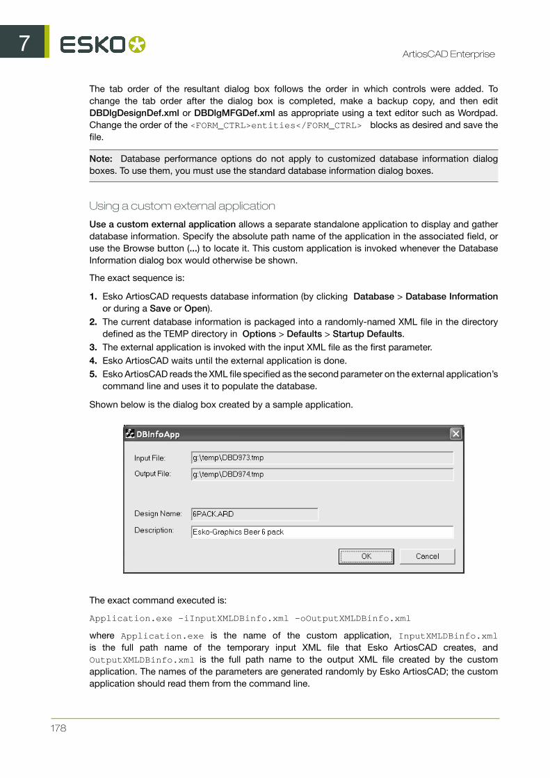
7ArtiosCAD Enterprise
178
The tab order of the resultant dialog box follows the order in which controls were added. Tochange the tab order after the dialog box is completed, make a backup copy, and then editDBDlgDesignDef.xml or DBDlgMFGDef.xml as appropriate using a text editor such as Wordpad.Change the order of the <FORM_CTRL>entities</FORM_CTRL> blocks as desired and save thefile.
Note: Database performance options do not apply to customized database information dialogboxes. To use them, you must use the standard database information dialog boxes.
Using a custom external application
Use a custom external application allows a separate standalone application to display and gatherdatabase information. Specify the absolute path name of the application in the associated field, oruse the Browse button (...) to locate it. This custom application is invoked whenever the DatabaseInformation dialog box would otherwise be shown.
The exact sequence is:
1. Esko ArtiosCAD requests database information (by clicking Database > Database Informationor during a Save or Open).
2. The current database information is packaged into a randomly-named XML file in the directorydefined as the TEMP directory in Options > Defaults > Startup Defaults.
3. The external application is invoked with the input XML file as the first parameter.4. Esko ArtiosCAD waits until the external application is done.5. Esko ArtiosCAD reads the XML file specified as the second parameter on the external application’s
command line and uses it to populate the database.
Shown below is the dialog box created by a sample application.
The exact command executed is:
Application.exe -iInputXMLDBinfo.xml -oOutputXMLDBinfo.xml
where Application.exe is the name of the custom application, InputXMLDBinfo.xmlis the full path name of the temporary input XML file that Esko ArtiosCAD creates, andOutputXMLDBinfo.xml is the full path name to the output XML file created by the customapplication. The names of the parameters are generated randomly by Esko ArtiosCAD; the customapplication should read them from the command line.

7ArtiosCAD Enterprise
179
Esko ArtiosCAD checks for a return code from the custom application of 1 for OK and 2 for Cancel.
A sample database definition XML file is shown below.
<ARTIOSDBDOC> <UNITS> IMPERIAL</UNITS> <DESIGN> <NAME> SAMPLE1.ARD</NAME> <REV> 0</REV> <REVNUM> 0</REVNUM> <PATH> C:\Artios\Designs\</PATH> <REVDATE> 2004-04-14</REVDATE> <SAVEDATE> 2004-04-14</SAVEDATE> <DESC> This is a sample long description</DESC> <SHORTDESC1> Short 1</SHORTDESC1> <SHORTDESC2> Short 2</SHORTDESC2> <SHORTDESC3> Short 3</SHORTDESC3> <AUTH> Authorization</AUTH> <REVDESC> Revision Description</REVDESC> <LENGTH> 8.000000</LENGTH> <WIDTH> 7.000000</WIDTH> <DEPTH> 6.000000</DEPTH> <GRAINDIR> 2</GRAINDIR> <CAL> 0.016000</CAL> <BLANKLEN> 780.256226</BLANKLEN> <BLANKHEIGHT> 558.799927</BLANKHEIGHT> <AREA> 267241.718750</AREA> <RULELEN> 5269.554688</RULELEN> <RESOURCE> <ID> 1</ID> <NAME> ArtiosCAD</NAME> <RELPATH> Artios\Designs</RELPATH> <PATH> C:\Artios\Designs</PATH> <MASTER>
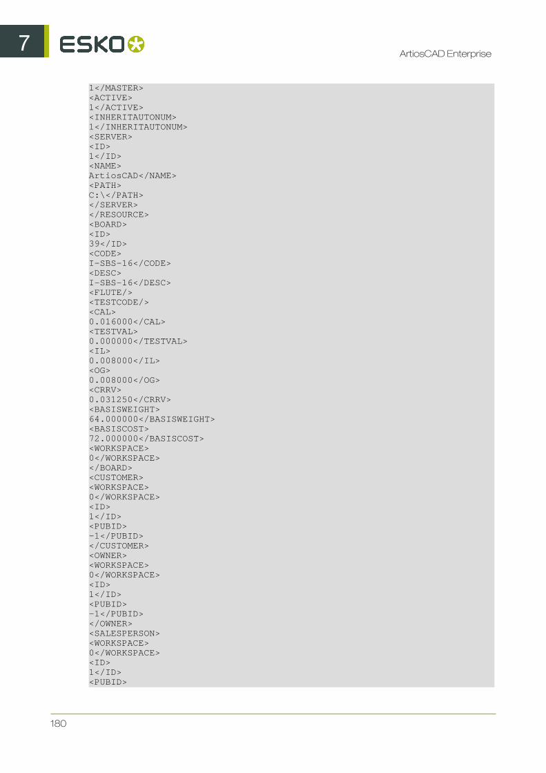
7ArtiosCAD Enterprise
180
1</MASTER> <ACTIVE> 1</ACTIVE> <INHERITAUTONUM> 1</INHERITAUTONUM> <SERVER> <ID> 1</ID> <NAME> ArtiosCAD</NAME> <PATH> C:\</PATH> </SERVER> </RESOURCE> <BOARD> <ID> 39</ID> <CODE> I-SBS-16</CODE> <DESC> I-SBS-16</DESC> <FLUTE/> <TESTCODE/> <CAL> 0.016000</CAL> <TESTVAL> 0.000000</TESTVAL> <IL> 0.008000</IL> <OG> 0.008000</OG> <CRRV> 0.031250</CRRV> <BASISWEIGHT> 64.000000</BASISWEIGHT> <BASISCOST> 72.000000</BASISCOST> <WORKSPACE> 0</WORKSPACE> </BOARD> <CUSTOMER> <WORKSPACE> 0</WORKSPACE> <ID> 1</ID> <PUBID> -1</PUBID> </CUSTOMER> <OWNER> <WORKSPACE> 0</WORKSPACE> <ID> 1</ID> <PUBID> -1</PUBID> </OWNER> <SALESPERSON> <WORKSPACE> 0</WORKSPACE> <ID> 1</ID> <PUBID>
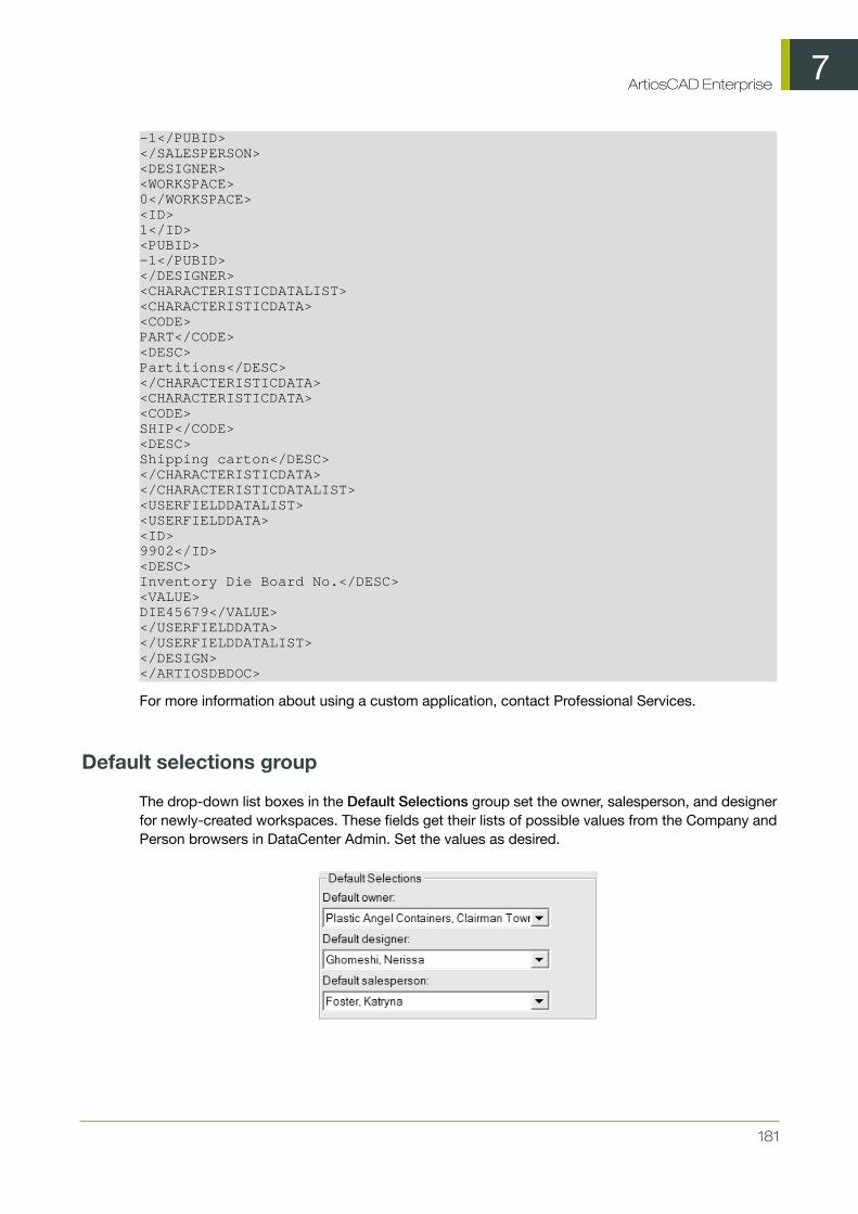
7ArtiosCAD Enterprise
181
-1</PUBID> </SALESPERSON> <DESIGNER> <WORKSPACE> 0</WORKSPACE> <ID> 1</ID> <PUBID> -1</PUBID> </DESIGNER> <CHARACTERISTICDATALIST> <CHARACTERISTICDATA> <CODE> PART</CODE> <DESC> Partitions</DESC> </CHARACTERISTICDATA> <CHARACTERISTICDATA> <CODE> SHIP</CODE> <DESC> Shipping carton</DESC> </CHARACTERISTICDATA> </CHARACTERISTICDATALIST> <USERFIELDDATALIST> <USERFIELDDATA> <ID> 9902</ID> <DESC> Inventory Die Board No.</DESC> <VALUE> DIE45679</VALUE> </USERFIELDDATA> </USERFIELDDATALIST> </DESIGN> </ARTIOSDBDOC>
For more information about using a custom application, contact Professional Services.
Default selections group
The drop-down list boxes in the Default Selections group set the owner, salesperson, and designerfor newly-created workspaces. These fields get their lists of possible values from the Company andPerson browsers in DataCenter Admin. Set the values as desired.

7ArtiosCAD Enterprise
182
Click OK to save the changes made to Database defaults and return to the main Defaults dialogbox. Click Apply to save the changes but remain in the Database defaults dialog box. To discard allchanges and return to the main Defaults dialog box, click Cancel.
Company selection display group
The option buttons in the Company Selection Display group control how company name andidentification information is shown in Esko ArtiosCAD. Name is the default choice.
Name and Number are fields you set for a company in the Company browser in DataCenter Admin.Note that Number can be any number you set; it is not calculated. Choose the display format asdesired.
Any changes made in this group will not appear in the Default Selections group in this dialog boxuntil you click OK and then open the Database defaults again.
Shown below is an example in the Oneup Database Information dialog box when Number, Name isthe chosen option in Company Selection Display.
Spell checking
If you have Microsoft Word installed on your system, Esko ArtiosCAD can use its spell checkingfunctionality in Single Design and Manufacturing in most places where you enter text using a field ina dialog box. This feature is turned on by default. You may turn it off in the Paragraph Text tool andin text fields by using the Spelling dialog box in the Startup Defaults catalog.

7ArtiosCAD Enterprise
183
Toggle the Enable spell checking checkbox as desired, and click OK to save the change and returnto the main Defaults dialog box.
Note: This setting does not affect document-wide spell check using Tools > Check Spelling. It isavailable regardless of the state of this checkbox.
Nudge Options and Defaults
Click Options > Nudge to set the active nudge modes per session and the distances they use. Thiscommand is available when a single design or a manufacturing file is open. Essentially the samedialog box is used in Defaults in Startup defaults > Nudge options.
Shown below is the Nudge options dialog box.
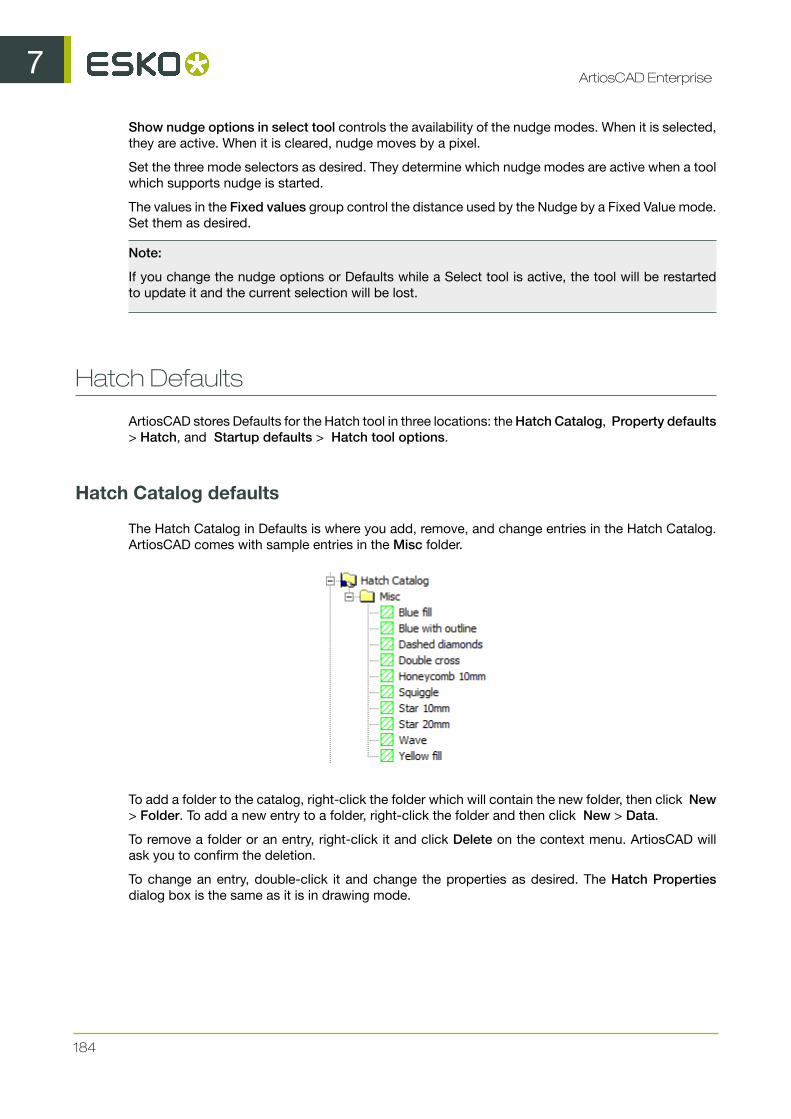
7ArtiosCAD Enterprise
184
Show nudge options in select tool controls the availability of the nudge modes. When it is selected,they are active. When it is cleared, nudge moves by a pixel.
Set the three mode selectors as desired. They determine which nudge modes are active when a toolwhich supports nudge is started.
The values in the Fixed values group control the distance used by the Nudge by a Fixed Value mode.Set them as desired.
Note:
If you change the nudge options or Defaults while a Select tool is active, the tool will be restartedto update it and the current selection will be lost.
Hatch Defaults
ArtiosCAD stores Defaults for the Hatch tool in three locations: the Hatch Catalog, Property defaults> Hatch, and Startup defaults > Hatch tool options.
Hatch Catalog defaults
The Hatch Catalog in Defaults is where you add, remove, and change entries in the Hatch Catalog.ArtiosCAD comes with sample entries in the Misc folder.
To add a folder to the catalog, right-click the folder which will contain the new folder, then click New> Folder. To add a new entry to a folder, right-click the folder and then click New > Data.
To remove a folder or an entry, right-click it and click Delete on the context menu. ArtiosCAD willask you to confirm the deletion.
To change an entry, double-click it and change the properties as desired. The Hatch Propertiesdialog box is the same as it is in drawing mode.

7ArtiosCAD Enterprise
185
Hatch Property defaults
In Property defaults > Hatch, you set the Defaults for the <custom> Hatch Catalog entry as shownbelow.

7ArtiosCAD Enterprise
186
The Hatch Properties are the same as in drawing mode; set them as desired and click OK to returnto Defaults.
Hatch Startup defaults
In Startup defaults > Hatch tool options, you set the options for how the Hatch tool will initially work.
In the Tool select option and Offsets groups, set the options as desired.
Prompt before changing layers, when checked, makes you confirm changing layers to the layerspecified in a Hatch Catalog entry’s Placement Options dialog box. Restore layer on tool exit, whenchecked, returns you to the layer you were in if the layer changed due to using a Hatch Catalog entrywith a layer assignment.
When you are done setting the options as desired, click OK to return to Defaults.
Adding LASERPOINT IQ standards to Style Catalogs
Preparation
Before adding a LASERPOINT IQ standard to Esko ArtiosCAD, it is necessary to locate theLASERPOINT IQ files needed to run the standard. The name can be determined using MenuManagement. Locate the standard to add and select the Edit option. This will show a standard namewhich looks like one of the following entries:
• EXE STDMENU WITH ‘XYZ’ This is an entry for a L ASERPOINT IQ 2.0 format standard whosename is XYZ. You will need the files XYZGEOM and XYZW.

7ArtiosCAD Enterprise
187
• XYZ. This is an entry for a pre-LASERPOINT IQ 2.0 standard whose name is XYZ. You will needthe file XYZ and there may also be a file called XYZW containing documentation plots.
The files for the standard you are migrating are probably in your \LP\USER_LIBI directory. Copythem to the \Artios\ArtiosCADn.nnll\ServerLib directory (where n.nn is the version numberof Esko ArtiosCAD and ll is the language.
Adding the standard to a Style Catalog
Add the LASERPOINT IQ standard to the Esko ArtiosCAD style catalog using Defaults in a similarway to normal Esko ArtiosCAD standards. Start Esko ArtiosCAD, and then open the style catalogas follows:
1. Click Options and Defaults to open the Defaults dialog box.2. Use the right mouse button to click Style Catalog in the left area of the dialog box and then click
New and Data.3. Type the descriptive name for the standard as you want it displayed in Esko ArtiosCAD.4. Double-click the icon beside the standard name to open the dialog box for specifying the
standard.
5. For LASERPOINT IQ 2-4 standards:
Type the name of the standard file without the W or GEOM suffix. In the example above with filesXYZW and XYZGEOM, type XYZ.
For pre-LASERPOINT IQ2 standards:
Type the name of the standard.
If you don’t know the name of the standard, click the … button at the end of the Filename field.This will open the standard Open dialog box which you can use to navigate to the proper directoryand open the file.
6. Click OK to close the dialog and save changes. Esko ArtiosCAD will check the file and set thestandard type automatically.
You are now ready to run the standard in Esko ArtiosCAD.

7ArtiosCAD Enterprise
188
Note: Move the standard to sub-folders in your style catalog if desired to give a more structuredorganization.
Troubleshooting newly-added INTERACT/LASERPOINT/ LASERPOINTIQ standards
Missing files
LASERPOINT IQ standards may be created based on other standards or attachments. You mustcopy the files for the standards to run in the Esko ArtiosCAD environment. Any missing files will beshown in error dialog boxes when a standard is run. Remember to copy all the files – for example, ifATTACHGEOM is missing, you will also need the associated ATTACHW file.
Changing the framework
Esko ArtiosCAD sets up a framework to execute the various types of INTERACT/LP/LASERPOINTIQ 1 standards. The framework settings are available by clicking the Advanced button.
LASERPOINT IQ 2-4 standards may need to be set up using the INTERACT type if they used elementsfrom before LASERPOINT IQ 2.0. This is set by changing to the standard type INTERACT/LP/IQ1,clicking Advanced, and selecting the framework Non-standard IQ2-4.
INTERACT/LP/IQ1 standards that fail to run properly can be tried with alternative frameworks byclicking Advanced and selecting one of:
• LP/IQ1• INTERACT design standard• Designer Edition
7ArtiosCAD Enterprise
189
Adding Designer WorkBench designs to Style Catalogs
Preparation
Before you can add Designer WorkBench designs to a Style Catalog, Esko ArtiosCAD needs to betold the location of the DWB resources. You will need to know the directories used for the DWBresources and then add these to the Esko ArtiosCAD environment. The steps to do this are:
1. Start DataCenter Admin and double-click Server.2. Check that there is a server set up for the drive letter where your DWB designs are located. Add
a new server as necessary. For example, if your DWB designs are on the D: drive, click the Inserticon, give the new server a name and select D: as the server path. Click Insert to add the server.
3. Double-click Resource.4. Do the following for each DWB resource:
Click the Insert icon, give the resource a name, pick the server and the path for the resource.Click Insert to add the resource.
5. When complete, save the changes and close DataCenter Admin.
Adding a Designer WorkBench standard to a Style Catalog
Any DWB design can be added to the Esko ArtiosCAD Style Catalog by using the followingprocedure:
1. Start Esko ArtiosCAD.2. Click Options and Defaults to open the Defaults dialog box.3. Use the right mouse button to click Style Catalog in Shared defaults and then click New and Data.4. Type the descriptive name for the standard as you want it displayed in Esko ArtiosCAD.5. Double-click the icon beside the standard name to open the dialog for specifying the standard.6. Click the … button beside the data entry area for the design name. This will show the Open dialog.7. Change to resource view, select the resource, and check you are showing designs of type either
All files or Designer Workbench Designs.8. Select the design and click Open.9. Close the Defaults dialog box and save changes.
You are now ready to run the standard in Esko ArtiosCAD.
Note: The standard can be moved to sub-folders in your style catalog, if desired, to give a morestructured organization.

7ArtiosCAD Enterprise
190
Default new design template
Each parameter set can now have a default single design template defined. This means that whenyou create a new single design by clicking New Design on the File menu, instead of getting a blankdesign, the standard you have associated with the parameter set will run and the new workspacewill inherit the results.
Double-clicking New Design Template opens the New Design Template dialog box for the currentparameter set. Select the Use Design Template checkbox and choose a standard from one of thecatalogs shown.

7ArtiosCAD Enterprise
191
Only standards of type ArtiosCAD can be used as new design templates, so only those are listedin the dialog box. INTERACT, LASERPOINT, and LASERPOINT IQ standards may not be used asdesign templates.
The design template does not have to draw any geometry - you can simply set default variables,menus, and layers in it, and they will be copied into each new workspace made by the template.
Settings in the parameter set for the board code, bridging formula, sideness, and property defaultstake precedence over those settings in the template.
The design template is used only when explicitly creating a new single design. It is not used whencreating a new embedded design in Manufacturing or when moving lines to a new design with theMove To Layer tool.
Default layers in Manufacturing
You can specify layers that will be created in new manufacturing files at creation and in existingmanufacturing files when they are opened.
To do this, do the following:
1. Start Esko ArtiosCAD and click Options > Defaults > Startup defaults > Default MFG UserLayers. The empty Default MFG User Layers dialog box will open.
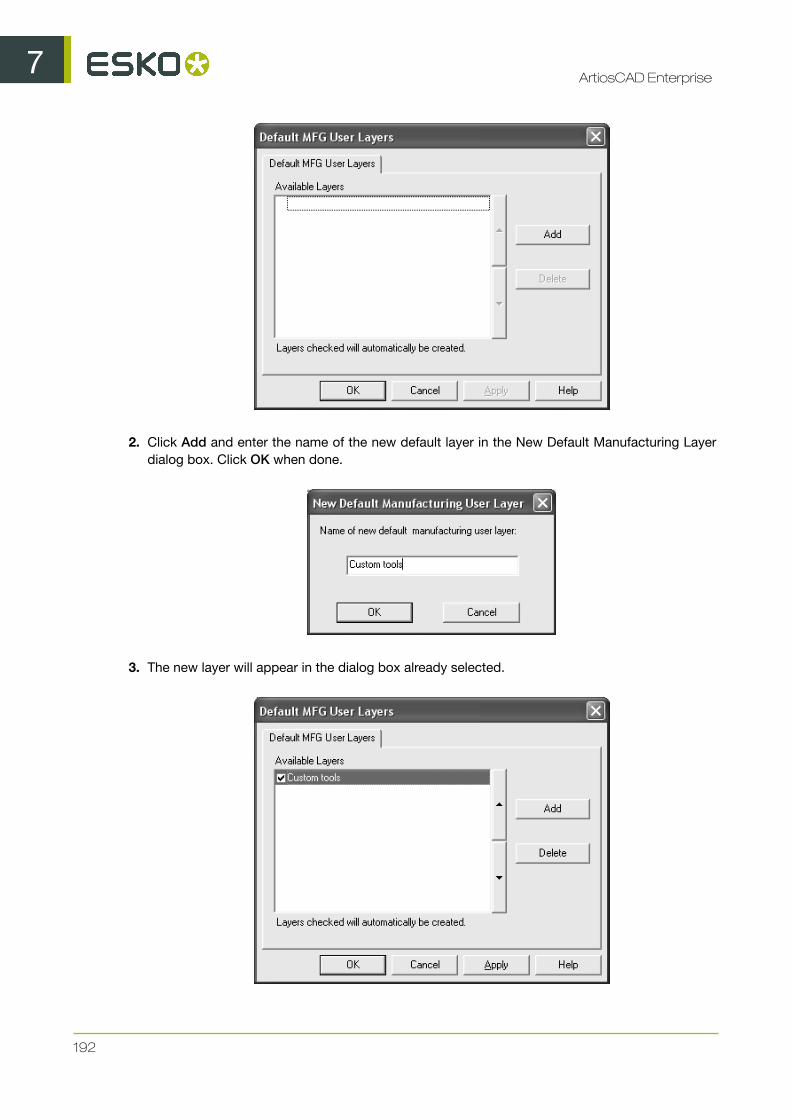
7ArtiosCAD Enterprise
192
2. Click Add and enter the name of the new default layer in the New Default Manufacturing Layerdialog box. Click OK when done.
3. The new layer will appear in the dialog box already selected.

7ArtiosCAD Enterprise
193
4. Continue adding layers as desired, clicking OK when done.5. Save and exit Defaults.
Layers which are not selected are not created automatically; however, they are available for pickingin the drop-down list box in the Create Layer dialog box in Manufacturing.
All of the default layers, whether created in the manufacturing file or not, will also be available forselection on the View tab of any Output when the User Defined layer set selection is active.

7ArtiosCAD Enterprise
194
Toolbars
In Esko ArtiosCAD you can change the background of toolbars and create customized toolbars tosuit your needs. As with other Defaults, you can define toolbars either on a per-machine basis (Userdefaults) or on a server basis (Shared defaults). Customized toolbars can contain buttons for EskoArtiosCAD tools, geometry macros, Outputs, and menu commands.
Customized toolbars
Customized toolbars are managed by the Customized Toolbars catalog in Defaults. Esko ArtiosCADdisplays up to 30 customized toolbars in Single Design and 30 customized toolbars in Manufacturing,with each toolbar holding a maximum of 15 items. You can define more than 30 customized toolbars

7ArtiosCAD Enterprise
195
per module, but Esko ArtiosCAD will display a random assortment in the Customized Toolbars MasterControl.
3D does not offer customized toolbars.
Each item on a customized toolbar must have a unique name. If there are items with the same name(for instance, one in Shared Defaults and one in User Defaults), Esko ArtiosCAD executes the firstone it finds when you click the button on the toolbar.
Shown below is the Customized Toolbars catalog in Server defaults. The individual folders are emptyuntil you create customized toolbars within them.
Icons for customized toolbars
By default, customized toolbars use the icon of a person’s head. You may design your own icons forcustomized toolbars using the 16 primary system colors. They must be 15 pixels high by 16 pixelswide in BMP format. Icons for Shared defaults must be saved in ServerLib, while icons for Userdefaults must be saved in ClientLib.
Each geometry macro and Output can have a customized icon as well. Follow the same rules forthem as those listed above for a customized toolbar icon. Specify the icon in the Icon for customtoolbar group in the Properties dialog box for the geometry macro, and in the Icon for custom toolbargroup on the Output Type tab of the Output’s Properties dialog box. If you changed the definition ofan Output to specify a custom icon, save the changes, and then exit and re-enter Defaults for thechanges to be shown.
You should create any desired icons before entering Defaults to create the customized toolbar.
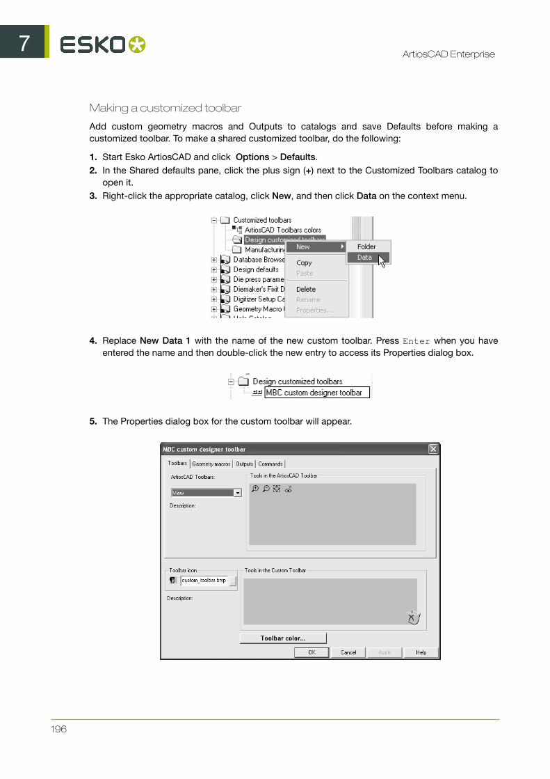
7ArtiosCAD Enterprise
196
Making a customized toolbar
Add custom geometry macros and Outputs to catalogs and save Defaults before making acustomized toolbar. To make a shared customized toolbar, do the following:
1. Start Esko ArtiosCAD and click Options > Defaults.2. In the Shared defaults pane, click the plus sign (+) next to the Customized Toolbars catalog to
open it.3. Right-click the appropriate catalog, click New, and then click Data on the context menu.
4. Replace New Data 1 with the name of the new custom toolbar. Press Enter when you haveentered the name and then double-click the new entry to access its Properties dialog box.
5. The Properties dialog box for the custom toolbar will appear.

7ArtiosCAD Enterprise
197
6. In the top half of the dialog box, choose the tab containing the item that will be replicated on thecustomized toolbar. Items from each category can be added to the same customized toolbar.
On the Toolbars tab, select the toolbar to copy from by using the ArtiosCAD Toolbars drop-downlist box. On the Geometry Macros and Outputs tabs, expand the catalogs to access the individualgeometry macros and Outputs. On the Commands tab, simply select the desired command.
7. Drag the desired tool, geometry macro, Output, or command from the top pane to the Tools inthe Custom Toolbar group. Repeat as desired, putting up to 15 items on the customized toolbar.Shown below is act of dragging a command to the Tools in the Custom Toolbar group.
8. To change the icon used for this customized toolbar in the Customized Toolbars Master Control,enter the name of the icon file you created previously and placed in ServerLib in the ToolbarIcon group.
To create a customized toolbar for users of the current machine only, create a new CustomizedToolbars catalog by right-clicking in the User defaults pane, clicking New, selecting Customizedtoolbars, and following the procedure above for Shared defaults.
To delete an item from a customized toolbar, drag it to the Recycle Bin icon at the bottom right ofthe Tools in the Custom Toolbar group.
To delete a custom toolbar, delete its entry from the catalog.
When adding an Output or a geometry macro to a toolbar, the number Esko ArtiosCAD assigns thebutton will remain static and cannot be changed by deleting other buttons.
Colored toolbars
Each toolbar in Esko ArtiosCAD can have a different background color to make it easier to identify.
Color definitions in User defaults override those set in Shared defaults.

7ArtiosCAD Enterprise
198
Colors on standard toolbars
To change the background color of a standard Esko ArtiosCAD toolbar, do the following:
1. Start Esko ArtiosCAD and click Options > Defaults.2. Open the appropriate Customized toolbars catalog (either the one in Shared defaults or one in
User Defaults) by clicking the plus sign (+) next to it.3. Double-click ArtiosCAD Toolbars colors. The ArtiosCAD Toolbars colors dialog box will appear.
4. Click the button of the toolbar to change and click Toolbar color to open the Toolbar color dialogbox.

7ArtiosCAD Enterprise
199
5. Click the color to set as the toolbar background and click OK.
To reset the toolbar background color to the default, click Set to System Color and then click OK.6. The Toolbar color button in the ArtiosCAD Toolbars colors dialog box will change to the color
you selected.7. Repeat steps 4 and 5 as desired. When done, click OK to return to Defaults, or click Cancel to
discard the changes.
Colors on customized toolbars
To change the background color of a customized toolbar, do the following:
1. Start Esko ArtiosCAD and click Options > Defaults.2. Open the Customized toolbars catalog (either the one in Shared defaults or one in User Defaults)
by clicking the plus sign (+) next to it.3. Open the Designer customized toolbars catalog or the Manufacturing customized toolbars
catalog by clicking the plus sign (+) next to it.4. Double-click the customized toolbar to change to open its Properties dialog box.5. Click Toolbar color.

7ArtiosCAD Enterprise
200
6. The Toolbar color dialog box will appear. Click the color to set as the toolbar background andclick OK.
To reset the toolbar background color to the default, click Set to System Color and then click OK.7. The Toolbar color button in the customized toolbar’s Properties dialog box will change to the
color you selected.8. Repeat as desired for other customized toolbars. When done, click OK to return to Defaults, or
click Cancel to discard the changes.
Shortcuts
Shortcuts are keyboard sequences that activate Esko ArtiosCAD commands, such as pressingCTRL-N for a new single design workspace. Shortcuts are organized by where they are used: 3D,Design, and Manufacturing. Shortcuts can also be assigned to Outputs and geometry macros.
Every menu command can have a shortcut assigned to it.
Shown below are the categories for menu commands in the Shortcuts Catalog in Shared Defaults.
To create menu command shortcuts in User Defaults, right-click in the User Defaults pane, clickNew, and then click Shortcuts. A Shortcuts Catalog is created with the three entries for the types of

7ArtiosCAD Enterprise
201
menu command shortcuts. Save the User Defaults after creating the Shortcuts Catalog but beforeadding to it.
Assigning a shortcut to a menu command
To assign a shortcut to a menu command, do the following:
1. Start Esko ArtiosCAD and click Options > Defaults.2. Scroll down the list of Shared Defaults, and open the Shortcuts Catalog by clicking the plus sign
(+) next to Shortcuts.3. Double-click the category for the desired new shortcut. In this example, the Direction menu
command on the View Options sub-menu of the View menu will be assigned a shortcut, so double-click the Design Shortcuts category. The Design Shortcuts dialog box opens as shown below.
4. Scroll down to the View menu, and double-click Direction under View Options.
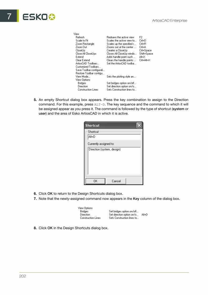
7ArtiosCAD Enterprise
202
5. An empty Shortcut dialog box appears. Press the key combination to assign to the Directioncommand. For this example, press ALT-D. The key sequence and the command to which it willbe assigned appear as you press it. The command is followed by the type of shortcut (system oruser) and the area of Esko ArtiosCAD in which it is active.
6. Click OK to return to the Design Shortcuts dialog box.7. Note that the newly-assigned command now appears in the Key column of the dialog box.
8. Click OK in the Design Shortcuts dialog box.
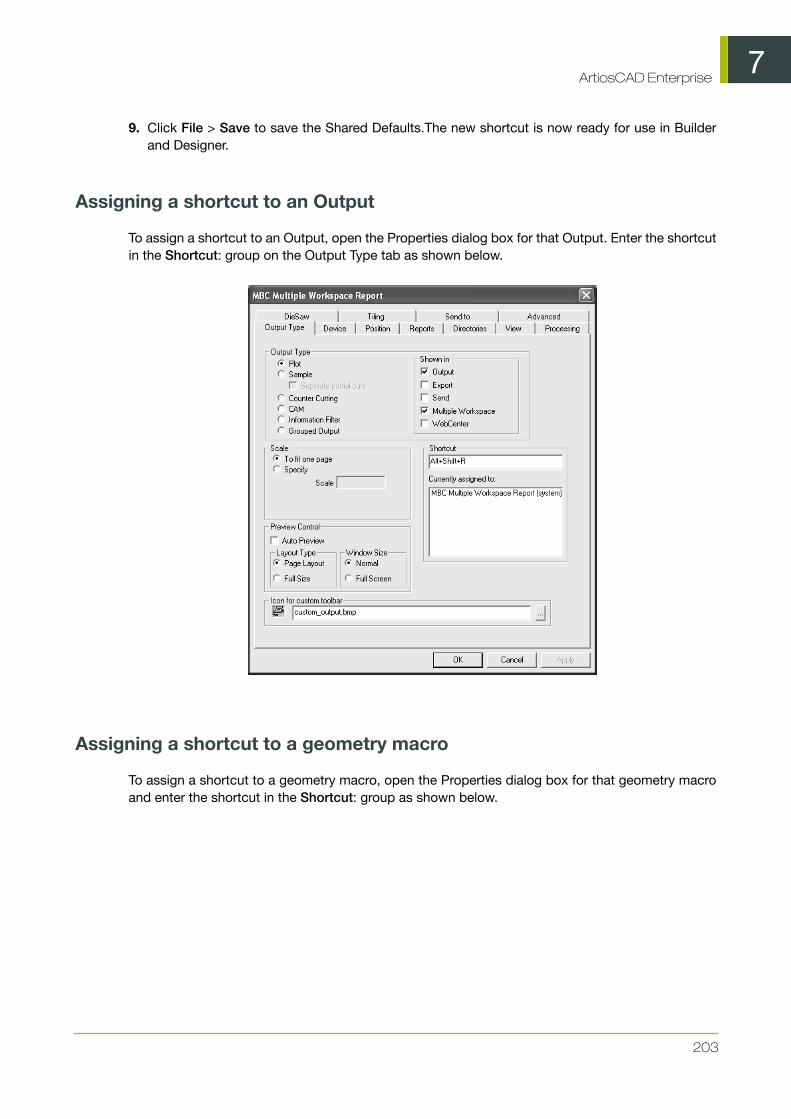
7ArtiosCAD Enterprise
203
9. Click File > Save to save the Shared Defaults.The new shortcut is now ready for use in Builderand Designer.
Assigning a shortcut to an Output
To assign a shortcut to an Output, open the Properties dialog box for that Output. Enter the shortcutin the Shortcut: group on the Output Type tab as shown below.
Assigning a shortcut to a geometry macro
To assign a shortcut to a geometry macro, open the Properties dialog box for that geometry macroand enter the shortcut in the Shortcut: group as shown below.
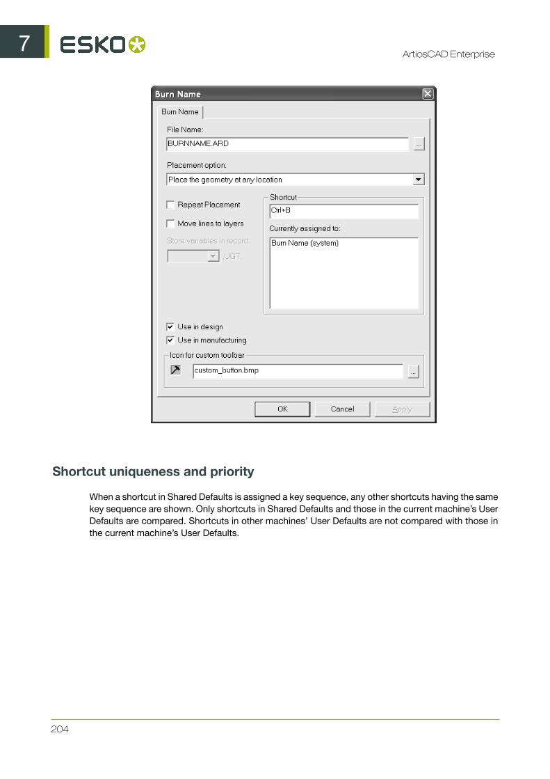
7ArtiosCAD Enterprise
204
Shortcut uniqueness and priority
When a shortcut in Shared Defaults is assigned a key sequence, any other shortcuts having the samekey sequence are shown. Only shortcuts in Shared Defaults and those in the current machine’s UserDefaults are compared. Shortcuts in other machines’ User Defaults are not compared with those inthe current machine’s User Defaults.

7ArtiosCAD Enterprise
205
The shortcut at the top of the list has the highest priority and will prevent other shortcuts assignedthe same key sequence in the same module from working. However, if the other key sequences arein other modules, there will be no conflict when the shortcut is used.
Shortcuts in User Defaults take priority over those in Shared Defaults. Within User Defaults, menuitems take priority over geometry macros, and geometry macros take priority over Outputs. If ashortcut is assigned to the same command in all three subcatalogs, the one in Design is listed first,then the one in Manufacturing, and finally the one in 3D.
Notes and warnings for Shortcuts
Only the first 300 shortcuts defined for geometry macros are active.
Counter layouts use the same shortcuts as Manufacturing.
When a geometry macro has a shortcut, and this geometry macro is present on a customized toolbar,and the geometry macro opens a dialog box, the button on the customized toolbar is not depressedwhen the geometry macro is activated by the shortcut.
There is only one set of user shortcuts per machine.
If you change shortcuts and exit without saving the changes, the uniqueness tests for successivechanges will not be accurate.
enter can not be used as any part of a shortcut.
Some shortcuts are permanent as shown in the table below.
Table: Permanent Shortcuts
Command Shortcut
Run Standard CTRL-2
New 3D CTRL-3
New Design CTRL-N
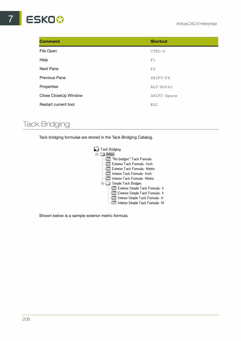
7ArtiosCAD Enterprise
206
Command Shortcut
File Open CTRL-O
Help F1
Next Pane F6
Previous Pane SHIFT-F6
Properties ALT-Enter
Close CloseUp Window SHIFT-Space
Restart current tool ESC
Tack Bridging
Tack bridging formulae are stored in the Tack Bridging Catalog.
Shown below is a sample exterior metric formula.
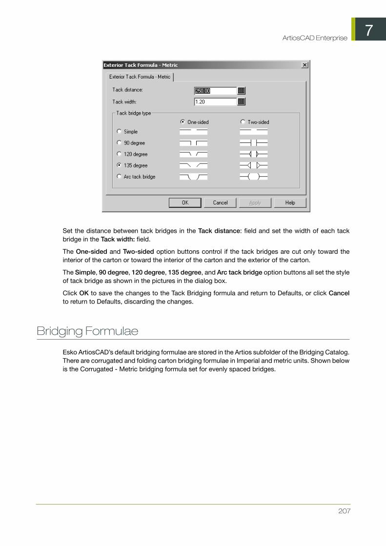
7ArtiosCAD Enterprise
207
Set the distance between tack bridges in the Tack distance: field and set the width of each tackbridge in the Tack width: field.
The One-sided and Two-sided option buttons control if the tack bridges are cut only toward theinterior of the carton or toward the interior of the carton and the exterior of the carton.
The Simple, 90 degree, 120 degree, 135 degree, and Arc tack bridge option buttons all set the styleof tack bridge as shown in the pictures in the dialog box.
Click OK to save the changes to the Tack Bridging formula and return to Defaults, or click Cancelto return to Defaults, discarding the changes.
Bridging Formulae
Esko ArtiosCAD’s default bridging formulae are stored in the Artios subfolder of the Bridging Catalog.There are corrugated and folding carton bridging formulae in Imperial and metric units. Shown belowis the Corrugated - Metric bridging formula set for evenly spaced bridges.

7ArtiosCAD Enterprise
208
The drop-down list box controls all the other settings in this dialog box. The No bridges selectionremoves all other settings from the dialog box. Evenly spaced and Inset distance from line end areexplained in the following sections.
Evenly spaced bridging formula
An evenly spaced bridging formula applies bridges based on the length of the line or arc. The sizeof the bridges is determined by the length of the line.
There are three groups of parameters in an evenly spaced bridging formula - Bridges on lines,Bridges on arcs, and Width of Bridges.
Bridges on lines and Bridges on arcs groups
The Bridges on lines and Bridges on arcs groups work similarly. A list of limits determines thenumber of bridges applied to lines or arcs. Shown below are the two groups in the Corrugated -Metric formula.
If the length of the line or arc is less than or equal to the value in the field, the integer to the left ofthe field is the number of bridges applied to the line or arc. If the length of the line or arc is greaterthan the value in the field, the limit is skipped and the next limit is applied. Click Add limit to add alimit; click Delete limit to delete a limit.
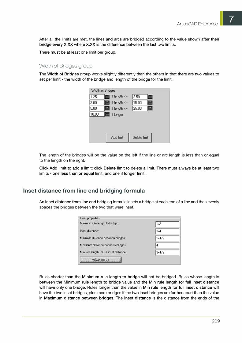
7ArtiosCAD Enterprise
209
After all the limits are met, the lines and arcs are bridged according to the value shown after thenbridge every X.XX where X.XX is the difference between the last two limits.
There must be at least one limit per group.
Width of Bridges group
The Width of Bridges group works slightly differently than the others in that there are two values toset per limit - the width of the bridge and length of the bridge for the limit.
The length of the bridges will be the value on the left if the line or arc length is less than or equalto the length on the right.
Click Add limit to add a limit; click Delete limit to delete a limit. There must always be at least twolimits - one less than or equal limit, and one if longer limit.
Inset distance from line end bridging formula
An Inset distance from line end bridging formula insets a bridge at each end of a line and then evenlyspaces the bridges between the two that were inset.
Rules shorter than the Minimum rule length to bridge will not be bridged. Rules whose length isbetween the Minimum rule length to bridge value and the Min rule length for full inset distancewill have only one bridge. Rules longer than the value in Min rule length for full inset distance willhave the two inset bridges, plus more bridges if the two inset bridges are further apart than the valuein Maximum distance between bridges. The Inset distance is the distance from the ends of the

7ArtiosCAD Enterprise
210
line to the centers of the inset bridges. Bridge centers can be no closer than the Minimum distancebetween bridges, and cannot be further apart than the Maximum distance between bridges.
The Advanced tab adds two parameters to the group:
These two fields are used when migrating bridging formulae from The Designer WorkBench into EskoArtiosCAD. Set the Inset factor to 0.285. The One Bridge Minimum equals the Minimum distance tobridge. The Inset Factor Limit is half the Maximum distance between bridges.
The options in the Width of Bridges group work the same for Inset formulae as they do for Evenlyspaced formulae.
Working with tuning catalog entries in Defaults
You will most likely need to create your own tuning catalog entries for PDF or DWG/DXF files as eachsupplier may produce them differently. The procedures for working with DWG/DXF tuning files arethe same as they are for PDF files; substitute the type of file you are working with as appropriate.Follow the instructions below to work with tuning catalog entries.
Creating a PDF vector import tuning catalog entry
ArtiosCAD comes with two example tuning files for importing PDF files as lines. However, sincepeople can create PDF files in many different ways, you may need many different tuning catalogentries to accommodate them.
To create a new PDF vector import tuning file, do the following:
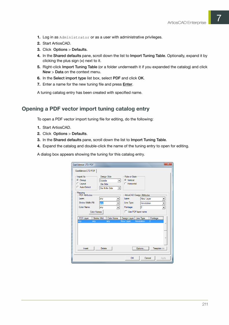
7ArtiosCAD Enterprise
211
1. Log in as Administrator or as a user with administrative privileges.
2. Start ArtiosCAD.
3. Click Options > Defaults.
4. In the Shared defaults pane, scroll down the list to Import Tuning Table. Optionally, expand it byclicking the plus sign (+) next to it.
5. Right-click Import Tuning Table (or a folder underneath it if you expanded the catalog) and clickNew > Data on the context menu.
6. In the Select import type list box, select PDF and click OK.
7. Enter a name for the new tuning file and press Enter.
A tuning catalog entry has been created with specified name.
Opening a PDF vector import tuning catalog entry
To open a PDF vector import tuning file for editing, do the following:
1. Start ArtiosCAD.
2. Click Options > Defaults.
3. In the Shared defaults pane, scroll down the list to Import Tuning Table.
4. Expand the catalog and double-click the name of the tuning entry to open for editing.
A dialog box appears showing the tuning for this catalog entry.
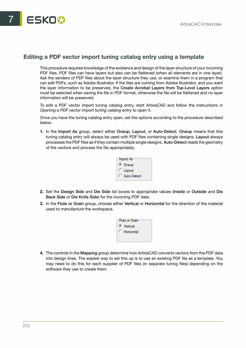
7ArtiosCAD Enterprise
212
Editing a PDF vector import tuning catalog entry using a template
This procedure requires knowledge of the existence and design of the layer structure of your incomingPDF files. PDF files can have layers but also can be flattened (when all elements are in one layer).Ask the senders of PDF files about the layer structure they use, or examine them in a program thatcan edit PDFs, such as Adobe Illustrator. If the files are coming from Adobe Illustrator, and you wantthe layer information to be preserved, the Create Acrobat Layers from Top-Level Layers optionmust be selected when saving the file in PDF format, otherwise the file will be flattened and no layerinformation will be preserved.
To edit a PDF vector import tuning catalog entry, start ArtiosCAD and follow the instructions inOpening a PDF vector import tuning catalog entry to open it.
Once you have the tuning catalog entry open, set the options according to the procedure describedbelow.
1. In the Import As group, select either Oneup, Layout, or Auto-Detect. Oneup means that thistuning catalog entry will always be used with PDF files containing single designs. Layout alwaysprocesses the PDF files as if they contain multiple single designs. Auto-Detect reads the geometryof the vectors and process the file appropriately.
2. Set the Design Side and Die Side list boxes to appropriate values (Inside or Outside and DieBack Side or Die Knife Side) for the incoming PDF data.
3. In the Flute or Grain group, choose either Vertical or Horizontal for the direction of the materialused to manufacture the workspace.
4. The controls in the Mapping group determine how ArtiosCAD converts vectors from the PDF datainto design lines. The easiest way to set this up is to use an existing PDF file as a template. Youmay need to do this for each supplier of PDF files (in separate tuning files) depending on thesoftware they use to create them.
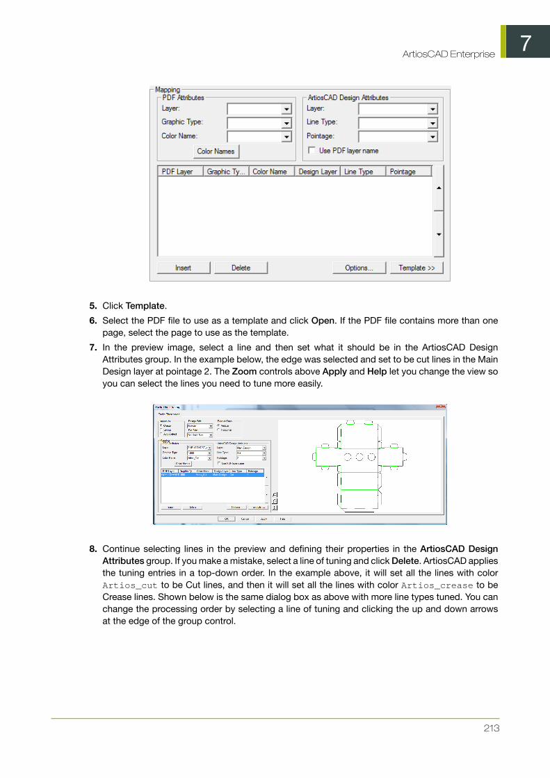
7ArtiosCAD Enterprise
213
5. Click Template.
6. Select the PDF file to use as a template and click Open. If the PDF file contains more than onepage, select the page to use as the template.
7. In the preview image, select a line and then set what it should be in the ArtiosCAD DesignAttributes group. In the example below, the edge was selected and set to be cut lines in the MainDesign layer at pointage 2. The Zoom controls above Apply and Help let you change the view soyou can select the lines you need to tune more easily.
8. Continue selecting lines in the preview and defining their properties in the ArtiosCAD DesignAttributes group. If you make a mistake, select a line of tuning and click Delete. ArtiosCAD appliesthe tuning entries in a top-down order. In the example above, it will set all the lines with colorArtios_cut to be Cut lines, and then it will set all the lines with color Artios_crease to beCrease lines. Shown below is the same dialog box as above with more line types tuned. You canchange the processing order by selecting a line of tuning and clicking the up and down arrowsat the edge of the group control.

7ArtiosCAD Enterprise
214
9. After you have finished selecting all the lines in the preview to tune, click Insert to add a final lineof tuning. This final line of tuning will send all lines that are not explicitly tuned to the Annotationlayer as 2-point Annotation lines.
a) For this final line of tuning, set the controls in the PDF attributes group to any, any, and any.b) In the ArtiosCAD Design Attributes group, set the Layer to Annotation, the Line type to
Annotation, and the Pointage to 2.
10.Click Color Names to change the names of the colors coming in from the tuning template. Inthe Color Names dialog box, you can rename an existing color by selecting it and changing theName: field. For example, if you have a color defined as 100% magenta, 30% yellow, and 15%black, you could select it and rename it reddish. You can also insert and delete color definitionsas desired using Insert and Delete, but selecting lines in the template is the intended way ofinserting color names initially.
a) There are two colors with special meaning. White matches all paths that have no colorassigned or that have 0% for all components. Uncolored matches all paths that are notrendered in the PDF file, such as guides and clipping paths.
11.Click Options to open the PDF Import Options dialog box.
a) Import text as outlines controls if text is imported or ignored and also controls the availabilityof the two sub-options. Add to annotation layer adds the text as outlines to an Annotationlayer using the Annotation line type. Add as fills to graphics layer adds the text to a Graphicslayer and fills it with the font color specified in the PDF file.
b) Change beziers to arcs changes beziers to arcs during the import process instead of havingto use the tool later.
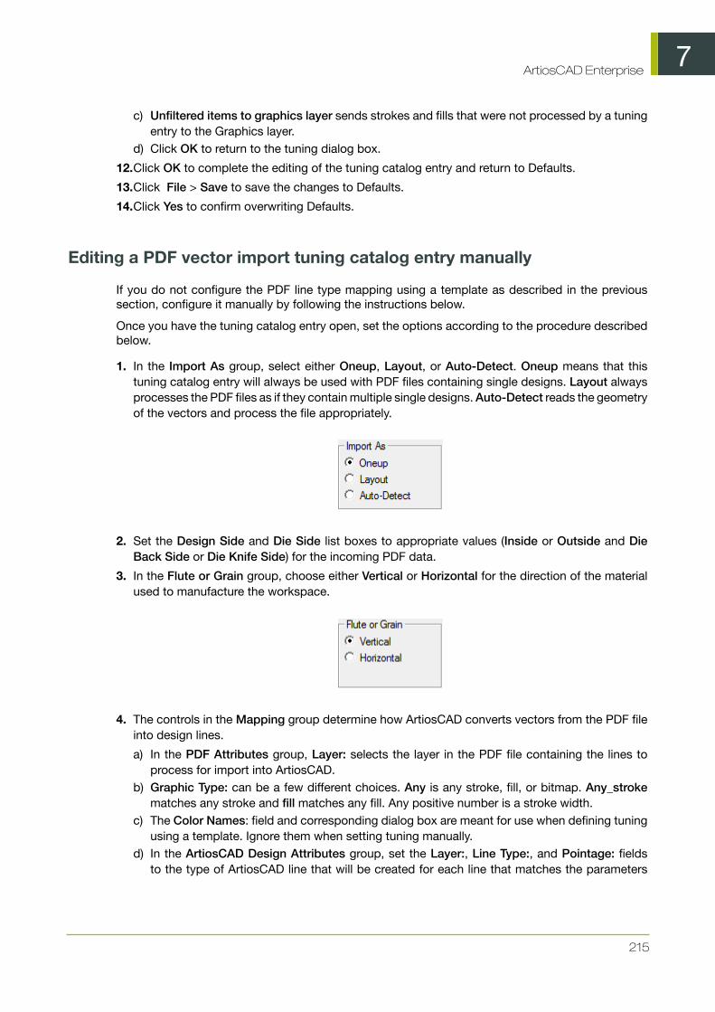
7ArtiosCAD Enterprise
215
c) Unfiltered items to graphics layer sends strokes and fills that were not processed by a tuningentry to the Graphics layer.
d) Click OK to return to the tuning dialog box.
12.Click OK to complete the editing of the tuning catalog entry and return to Defaults.
13.Click File > Save to save the changes to Defaults.
14.Click Yes to confirm overwriting Defaults.
Editing a PDF vector import tuning catalog entry manually
If you do not configure the PDF line type mapping using a template as described in the previoussection, configure it manually by following the instructions below.
Once you have the tuning catalog entry open, set the options according to the procedure describedbelow.
1. In the Import As group, select either Oneup, Layout, or Auto-Detect. Oneup means that thistuning catalog entry will always be used with PDF files containing single designs. Layout alwaysprocesses the PDF files as if they contain multiple single designs. Auto-Detect reads the geometryof the vectors and process the file appropriately.
2. Set the Design Side and Die Side list boxes to appropriate values (Inside or Outside and DieBack Side or Die Knife Side) for the incoming PDF data.
3. In the Flute or Grain group, choose either Vertical or Horizontal for the direction of the materialused to manufacture the workspace.
4. The controls in the Mapping group determine how ArtiosCAD converts vectors from the PDF fileinto design lines.
a) In the PDF Attributes group, Layer: selects the layer in the PDF file containing the lines toprocess for import into ArtiosCAD.
b) Graphic Type: can be a few different choices. Any is any stroke, fill, or bitmap. Any_strokematches any stroke and fill matches any fill. Any positive number is a stroke width.
c) The Color Names: field and corresponding dialog box are meant for use when defining tuningusing a template. Ignore them when setting tuning manually.
d) In the ArtiosCAD Design Attributes group, set the Layer:, Line Type:, and Pointage: fieldsto the type of ArtiosCAD line that will be created for each line that matches the parameters
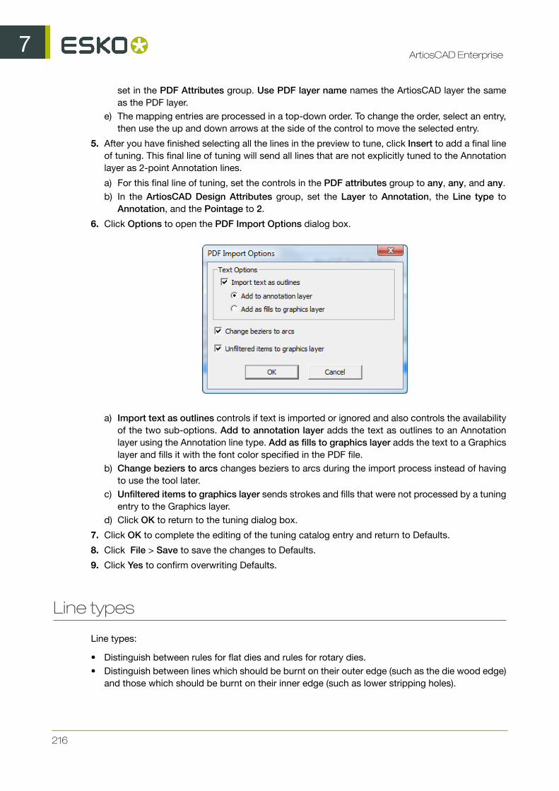
7ArtiosCAD Enterprise
216
set in the PDF Attributes group. Use PDF layer name names the ArtiosCAD layer the sameas the PDF layer.
e) The mapping entries are processed in a top-down order. To change the order, select an entry,then use the up and down arrows at the side of the control to move the selected entry.
5. After you have finished selecting all the lines in the preview to tune, click Insert to add a final lineof tuning. This final line of tuning will send all lines that are not explicitly tuned to the Annotationlayer as 2-point Annotation lines.
a) For this final line of tuning, set the controls in the PDF attributes group to any, any, and any.b) In the ArtiosCAD Design Attributes group, set the Layer to Annotation, the Line type to
Annotation, and the Pointage to 2.
6. Click Options to open the PDF Import Options dialog box.
a) Import text as outlines controls if text is imported or ignored and also controls the availabilityof the two sub-options. Add to annotation layer adds the text as outlines to an Annotationlayer using the Annotation line type. Add as fills to graphics layer adds the text to a Graphicslayer and fills it with the font color specified in the PDF file.
b) Change beziers to arcs changes beziers to arcs during the import process instead of havingto use the tool later.
c) Unfiltered items to graphics layer sends strokes and fills that were not processed by a tuningentry to the Graphics layer.
d) Click OK to return to the tuning dialog box.
7. Click OK to complete the editing of the tuning catalog entry and return to Defaults.
8. Click File > Save to save the changes to Defaults.
9. Click Yes to confirm overwriting Defaults.
Line types
Line types:
• Distinguish between rules for flat dies and rules for rotary dies.• Distinguish between lines which should be burnt on their outer edge (such as the die wood edge)
and those which should be burnt on their inner edge (such as lower stripping holes).
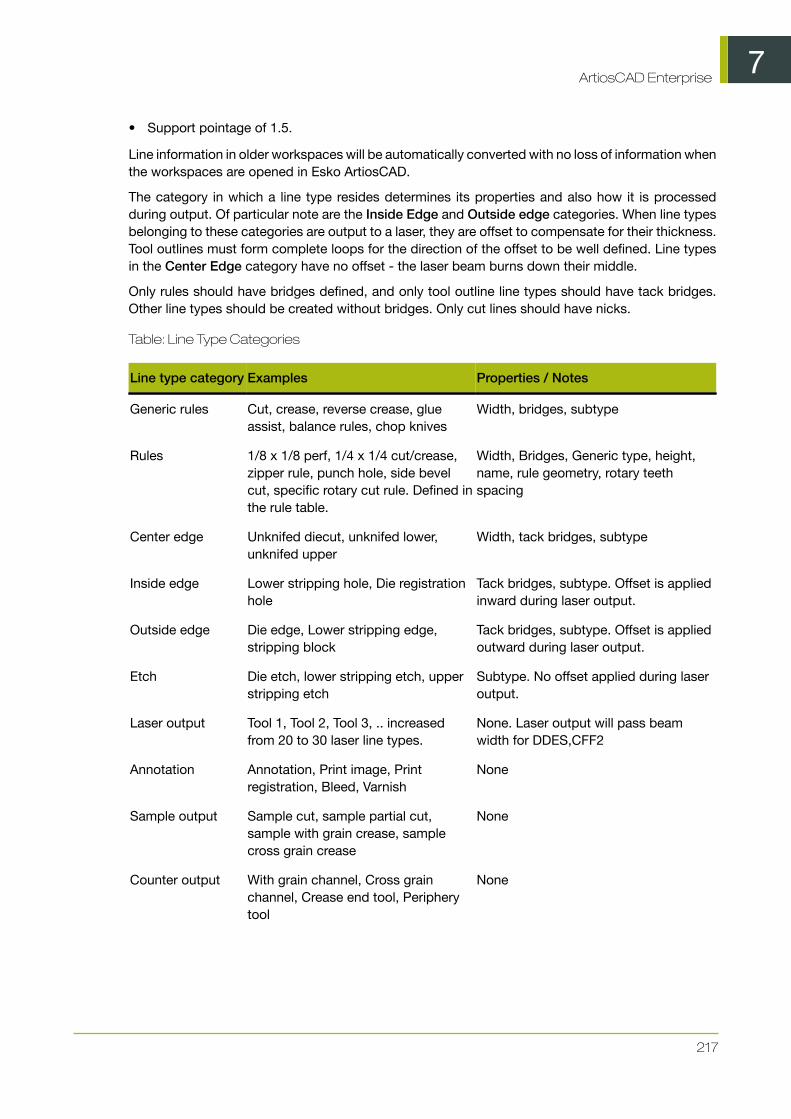
7ArtiosCAD Enterprise
217
• Support pointage of 1.5.
Line information in older workspaces will be automatically converted with no loss of information whenthe workspaces are opened in Esko ArtiosCAD.
The category in which a line type resides determines its properties and also how it is processedduring output. Of particular note are the Inside Edge and Outside edge categories. When line typesbelonging to these categories are output to a laser, they are offset to compensate for their thickness.Tool outlines must form complete loops for the direction of the offset to be well defined. Line typesin the Center Edge category have no offset - the laser beam burns down their middle.
Only rules should have bridges defined, and only tool outline line types should have tack bridges.Other line types should be created without bridges. Only cut lines should have nicks.
Table: Line Type Categories
Line type category Examples Properties / Notes
Generic rules Cut, crease, reverse crease, glueassist, balance rules, chop knives
Width, bridges, subtype
Rules 1/8 x 1/8 perf, 1/4 x 1/4 cut/crease,zipper rule, punch hole, side bevelcut, specific rotary cut rule. Defined inthe rule table.
Width, Bridges, Generic type, height,name, rule geometry, rotary teethspacing
Center edge Unknifed diecut, unknifed lower,unknifed upper
Width, tack bridges, subtype
Inside edge Lower stripping hole, Die registrationhole
Tack bridges, subtype. Offset is appliedinward during laser output.
Outside edge Die edge, Lower stripping edge,stripping block
Tack bridges, subtype. Offset is appliedoutward during laser output.
Etch Die etch, lower stripping etch, upperstripping etch
Subtype. No offset applied during laseroutput.
Laser output Tool 1, Tool 2, Tool 3, .. increasedfrom 20 to 30 laser line types.
None. Laser output will pass beamwidth for DDES,CFF2
Annotation Annotation, Print image, Printregistration, Bleed, Varnish
None
Sample output Sample cut, sample partial cut,sample with grain crease, samplecross grain crease
None
Counter output With grain channel, Cross grainchannel, Crease end tool, Peripherytool
None

7ArtiosCAD Enterprise
218
Subtypes
A subtype is a definition to further classify a type of line - it is a label only and is used for sortingthe tool assignment data when performing a CAM Output. Subtypes can have their own entries inAdvanced plotting styles. Up to 100 subtypes can be defined in the Subtype Mapping Catalog.
To define a subtype, select it, and enter the description of the subtype in the Description: field.Repeat as desired, and when done, click OK to save the definitions or Cancel to ignore them andreturn to Defaults.

7ArtiosCAD Enterprise
219
Plotting Styles
Plotting styles control the appearance of lines on screen and how lines are drawn or made on printers,plotters, samplemakers, and countercutters. Plotting styles control the colors, widths, and stylesused. They also control which physical tool an output device uses to construct the line.
Note: Plotting styles are not used to configure CAM outputs such as lasers and Kongsberg DieSaws;output to those types of devices is configured using the CAM Tooling Setup catalog.
Each plotter, samplemaker, and countercutter should have its own plotting style configured aseach has a different tool configuration. Most known output devices have plotting styles defined inthe example CAM Outputs configuration file, located in ..\InstLib\eg_cam_outputs.adf. Toview the example CAM Outputs, simply open that file in Defaults, open the Plotting Style Catalogit contains, and drag the appropriate entry into the Plotting Style Catalog in the Shared defaultspane. The names may contain CAM, but rest assured these are for plotters, samplemakers, andcountercutters.
Plotting styles may be either simple (the default) or advanced. Simple plotting styles configure theline color, line width, line style, and tool number based solely on a line type. Advanced plotting stylesdo the same configuration, but can be based on line type, subtype, and pointage instead of just linetype. An Advanced plotting style can not revert to a Simple plotting style.
Working with simple plotting styles
When the Advanced checkbox in the Line Types group is clear, the current plotting style is consideredsimple. In a simple plotting style, the line types are organized on five tabs - Design, Manufacturing,Sample, Tooling, and Counter.

7ArtiosCAD Enterprise
220
On each tab are the line types relevant to each label. For examples, the Design tab lists such typesas Cut, Crease, Partial cut, and so forth. The Manufacturing tab contains line types used in theManufacturing module, such as Stripping Rule, Die board edge, and Unknifed blanker. The sameis true for the other tabs.
When looking at the line types, shown first is the line type name, then an example of the line typeusing the attributes selected in the right pane, and finally the tool number. When creating a newplotting style, all the tool numbers are set to zero by default.
Creating a new simple plotting style
To create a completely new simple plotting style, do the following:
1. Right-click the Plotting Style Catalog entry in Defaults and click New > Data on the contextmenus that appear.
2. Enter a name for the new plotting style and press ENTER.3. Double-click the style to access its property page in order to change its defaults. The window
should appear similar to the one shown below.

7ArtiosCAD Enterprise
221
On the left is a set of five tabs that correspond to the different categories of lines. Each tab hasa control showing the line name, the line style, the line color, and the currently-assigned toolnumber. On the right are controls to set those attributes.
Checking the Output Only checkbox makes this plotting style available only when configuring anOutput - it is hidden when changing the plotting style in the View Mode.
Save as XML saves the plotting style as an XML file for use with the WebCenter Viewer.
For outputs, the tool number applies only when this plotting style will be used in an Outputdefinition using a CAM driver.
For outputs, the Color and Line Width apply only when this plotting style will be used in an Outputdefinition using either a Windows driver or a graphic CAM driver such as the PCL driver usedfor sample printing.
Copy From Style copies attributes of another plotting style into the current one.4. Click each line style and set the line attributes as desired.5. Click OK to save the changes to return to Defaults, or click Cancel to discard them and return
to Defaults.
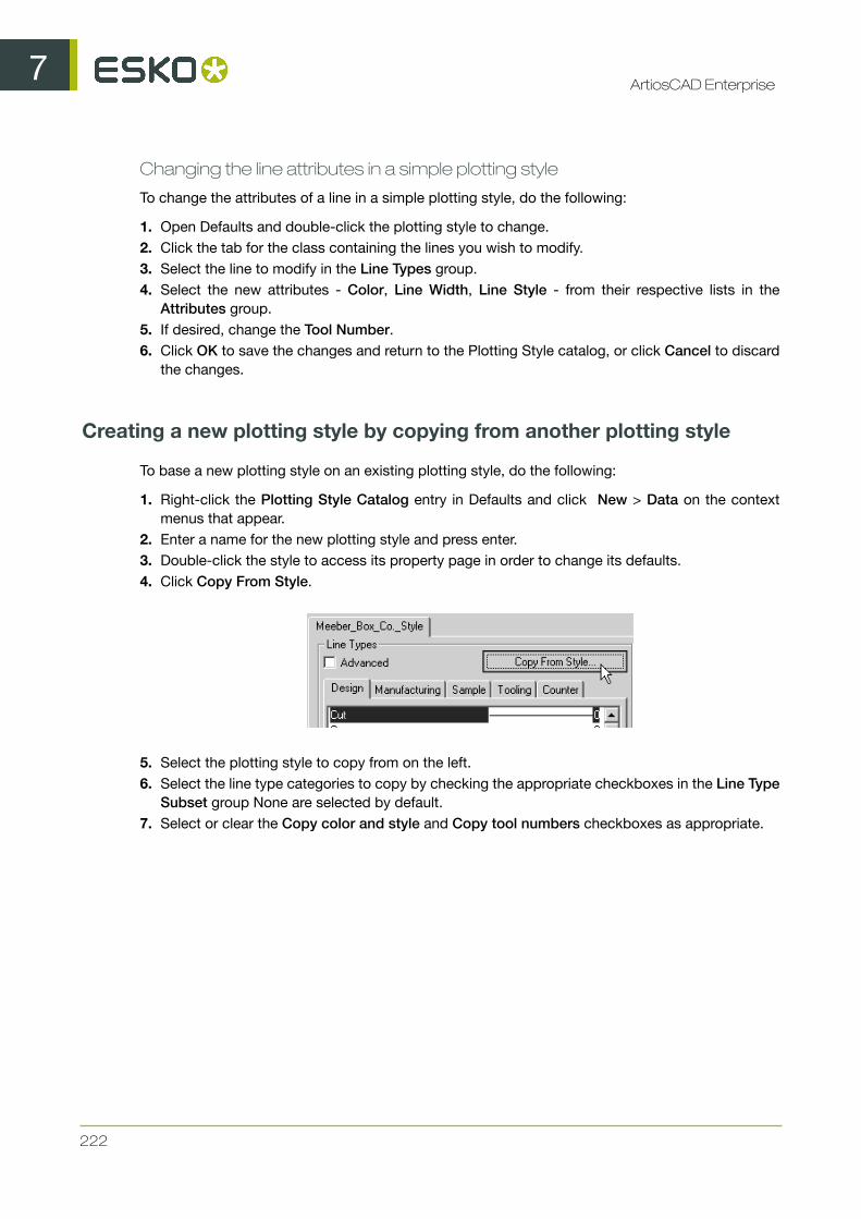
7ArtiosCAD Enterprise
222
Changing the line attributes in a simple plotting style
To change the attributes of a line in a simple plotting style, do the following:
1. Open Defaults and double-click the plotting style to change.2. Click the tab for the class containing the lines you wish to modify.3. Select the line to modify in the Line Types group.4. Select the new attributes - Color, Line Width, Line Style - from their respective lists in the
Attributes group.5. If desired, change the Tool Number.6. Click OK to save the changes and return to the Plotting Style catalog, or click Cancel to discard
the changes.
Creating a new plotting style by copying from another plotting style
To base a new plotting style on an existing plotting style, do the following:
1. Right-click the Plotting Style Catalog entry in Defaults and click New > Data on the contextmenus that appear.
2. Enter a name for the new plotting style and press enter.3. Double-click the style to access its property page in order to change its defaults.4. Click Copy From Style.
5. Select the plotting style to copy from on the left.6. Select the line type categories to copy by checking the appropriate checkboxes in the Line Type
Subset group None are selected by default.7. Select or clear the Copy color and style and Copy tool numbers checkboxes as appropriate.
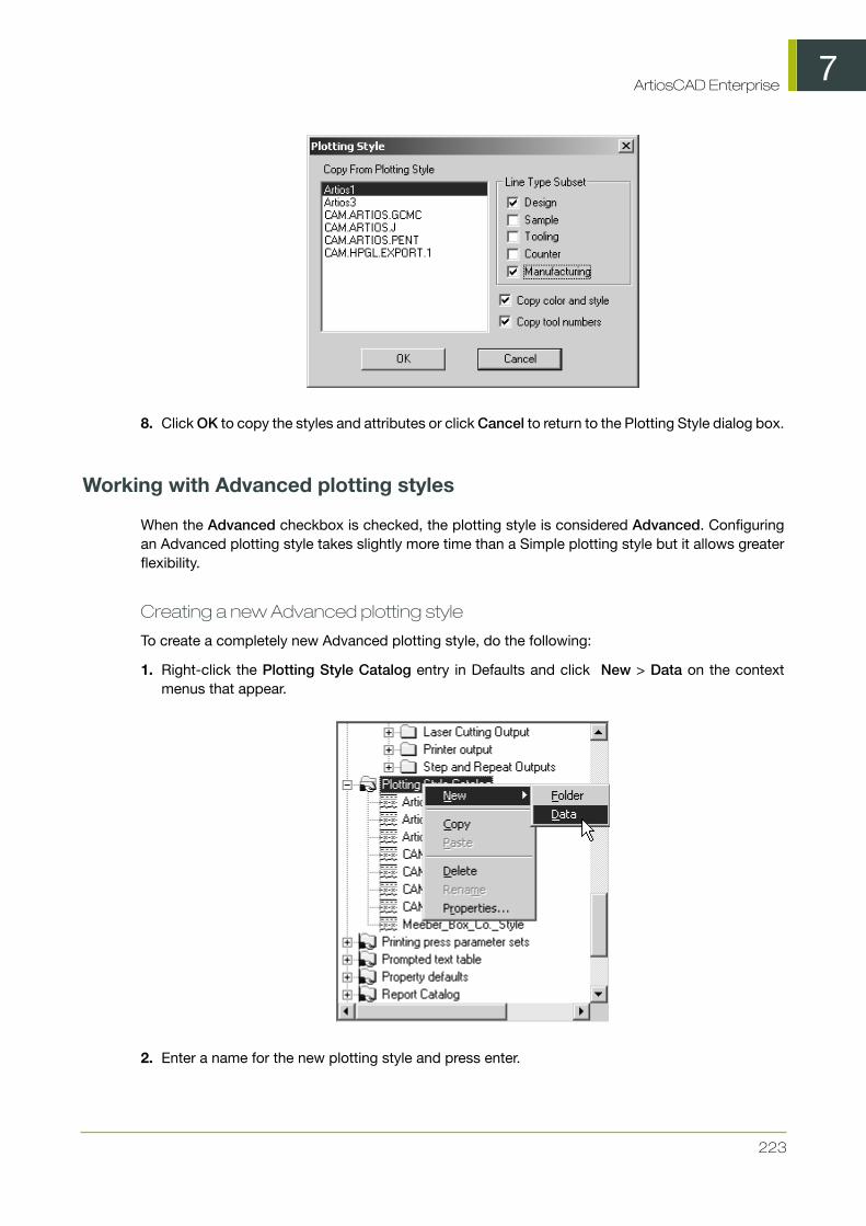
7ArtiosCAD Enterprise
223
8. Click OK to copy the styles and attributes or click Cancel to return to the Plotting Style dialog box.
Working with Advanced plotting styles
When the Advanced checkbox is checked, the plotting style is considered Advanced. Configuringan Advanced plotting style takes slightly more time than a Simple plotting style but it allows greaterflexibility.
Creating a new Advanced plotting style
To create a completely new Advanced plotting style, do the following:
1. Right-click the Plotting Style Catalog entry in Defaults and click New > Data on the contextmenus that appear.
2. Enter a name for the new plotting style and press enter.

7ArtiosCAD Enterprise
224
3. Double-click the style to access its property page in order to change its defaults and click theAdvanced checkbox. You will be asked to choose whether to keep the definitions from the simplestyle or to create a blank style. For the purposes of this workflow, choose Initialize to blank styleand click OK.
4. The blank Advanced style appears as shown below.
The Attributes group for an Advanced plotting style works in the same way as it does for a Simpleplotting style. The Line Types group, however, works differently as explained below.
5. In a newly-created advanced plotting style, as seen in the Line Types group, all lines areconfigured to be shown as solid line style, black color, 1.00 width, and tool 0.
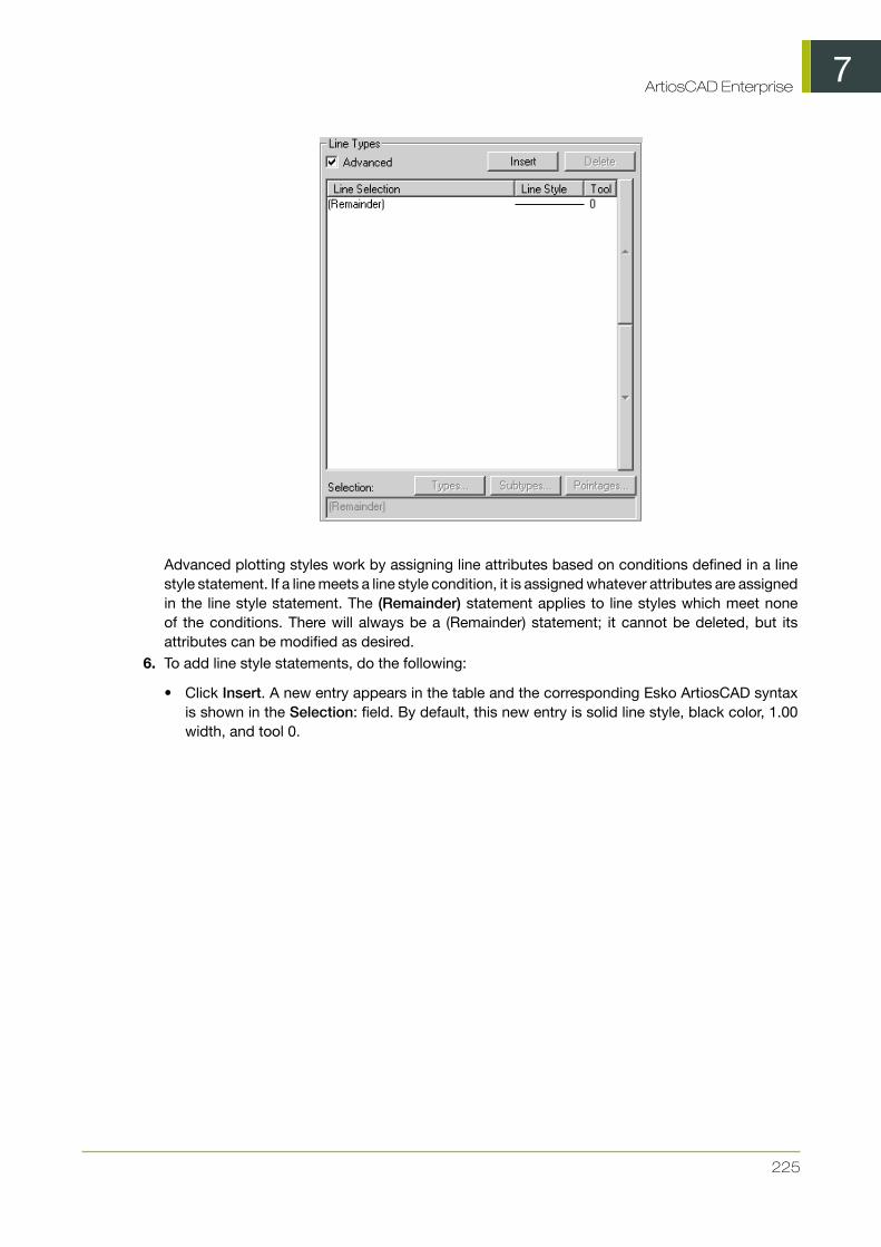
7ArtiosCAD Enterprise
225
Advanced plotting styles work by assigning line attributes based on conditions defined in a linestyle statement. If a line meets a line style condition, it is assigned whatever attributes are assignedin the line style statement. The (Remainder) statement applies to line styles which meet noneof the conditions. There will always be a (Remainder) statement; it cannot be deleted, but itsattributes can be modified as desired.
6. To add line style statements, do the following:
• Click Insert. A new entry appears in the table and the corresponding Esko ArtiosCAD syntaxis shown in the Selection: field. By default, this new entry is solid line style, black color, 1.00width, and tool 0.
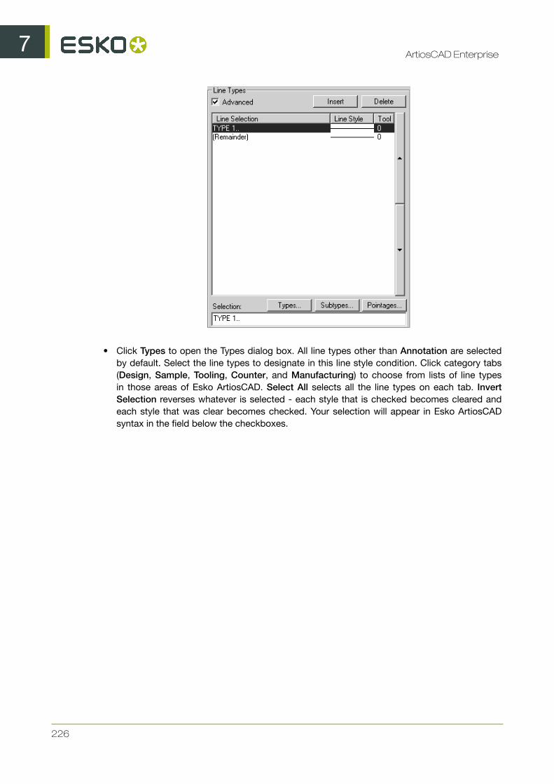
7ArtiosCAD Enterprise
226
• Click Types to open the Types dialog box. All line types other than Annotation are selectedby default. Select the line types to designate in this line style condition. Click category tabs(Design, Sample, Tooling, Counter, and Manufacturing) to choose from lists of line typesin those areas of Esko ArtiosCAD. Select All selects all the line types on each tab. InvertSelection reverses whatever is selected - each style that is checked becomes cleared andeach style that was clear becomes checked. Your selection will appear in Esko ArtiosCADsyntax in the field below the checkboxes.
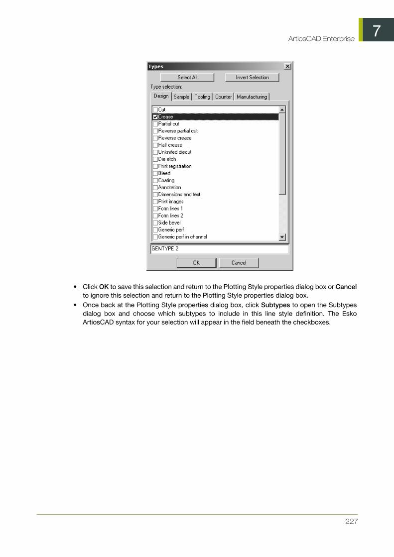
7ArtiosCAD Enterprise
227
• Click OK to save this selection and return to the Plotting Style properties dialog box or Cancelto ignore this selection and return to the Plotting Style properties dialog box.
• Once back at the Plotting Style properties dialog box, click Subtypes to open the Subtypesdialog box and choose which subtypes to include in this line style definition. The EskoArtiosCAD syntax for your selection will appear in the field beneath the checkboxes.
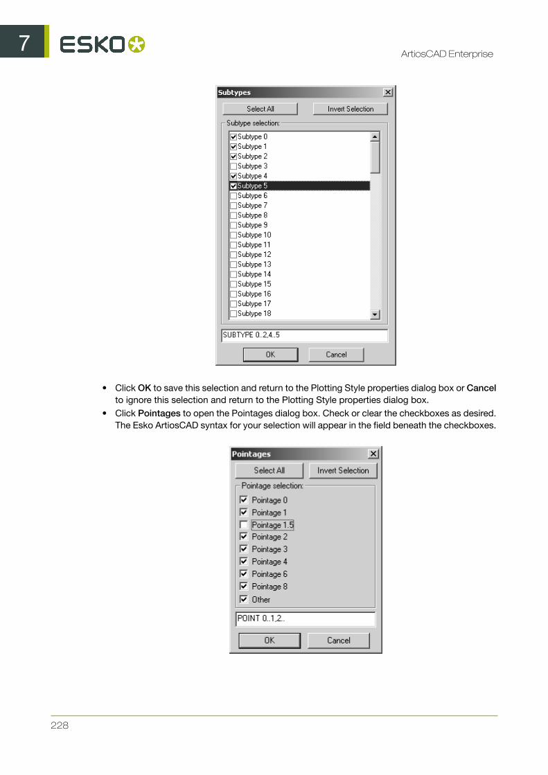
7ArtiosCAD Enterprise
228
• Click OK to save this selection and return to the Plotting Style properties dialog box or Cancelto ignore this selection and return to the Plotting Style properties dialog box.
• Click Pointages to open the Pointages dialog box. Check or clear the checkboxes as desired.The Esko ArtiosCAD syntax for your selection will appear in the field beneath the checkboxes.

7ArtiosCAD Enterprise
229
• Click OK to save this selection and return to the Plotting Style properties dialog box or Cancelto ignore this selection and return to the Plotting Style properties dialog box.
• Do not forget to also change the line attributes (color, line width, line style, and tool number) ifyou do not want them to be the default of black, 1.00, solid, and 0. Shown below is an exampleof crease line subtypes 0 through 2 and 4 through 5, pointage 0 through 1 and 2 and greatermade to be red, have a line width of 1.00, a style of dot-dash, and output on tool 2.
• If you are familiar with Esko ArtiosCAD syntax, you may edit the Selection: field directly.7. Repeat step 5 for each line style statement you wish to make. Shown below is the Artios.Pointage
style which is based on line pointage; it uses a different color and tool number for each pointage.

7ArtiosCAD Enterprise
230
8. When you have finished adding line style statements, click OK to save the changes to the plottingstyle or click Cancel to ignore them and return to Defaults.
9. Save the Defaults by clicking File > Save and clicking Yes when prompted to overwrite theexisting Defaults.
Converting a simple plotting style to an Advanced plotting style
When you convert a simple plotting style to an Advanced plotting style by checking the Advancedcheckbox in a simple plotting style definition, you can choose to preserve the line style definitions,or you can initialize the Advanced plotting style with no values. Preserving the settings of the simpleplotting style results in an Advanced plotting style similar to the one shown below. Initializing a blankplotting style results in having to define every line type as described in the previous section. In eithercase, edit the properties as desired. When done, click OK to accept the changes, or click Cancelto discard them.

7ArtiosCAD Enterprise
231
Special Rule Types
Esko ArtiosCAD provides a series of generic rule types such as cut and crease. These are usedat the design phase when how the line is cut or creased is unimportant or not known. There areother generic rule types, for example, for cut-crease lines. It is often necessary to specify that a cut-crease line is in fact ½” cut by ½” crease with crease used as the end land. In this case, a specialrule should be used.
Special rules may also be used for simple cut and crease rules to allow more specific control duringmanufacturing. For example:
• Helmold 3pt 0.937” cut rule• Böhler 3pt 23.6mm SN1 notched cutting rule
Specific bridging methods, rule widths, subtypes (for special cutting characteristics), and labels canbe associated with special rules which aid in the flat and rotary die manufacturing process. Shownbelow is the Special Rule Types Catalog in Defaults.
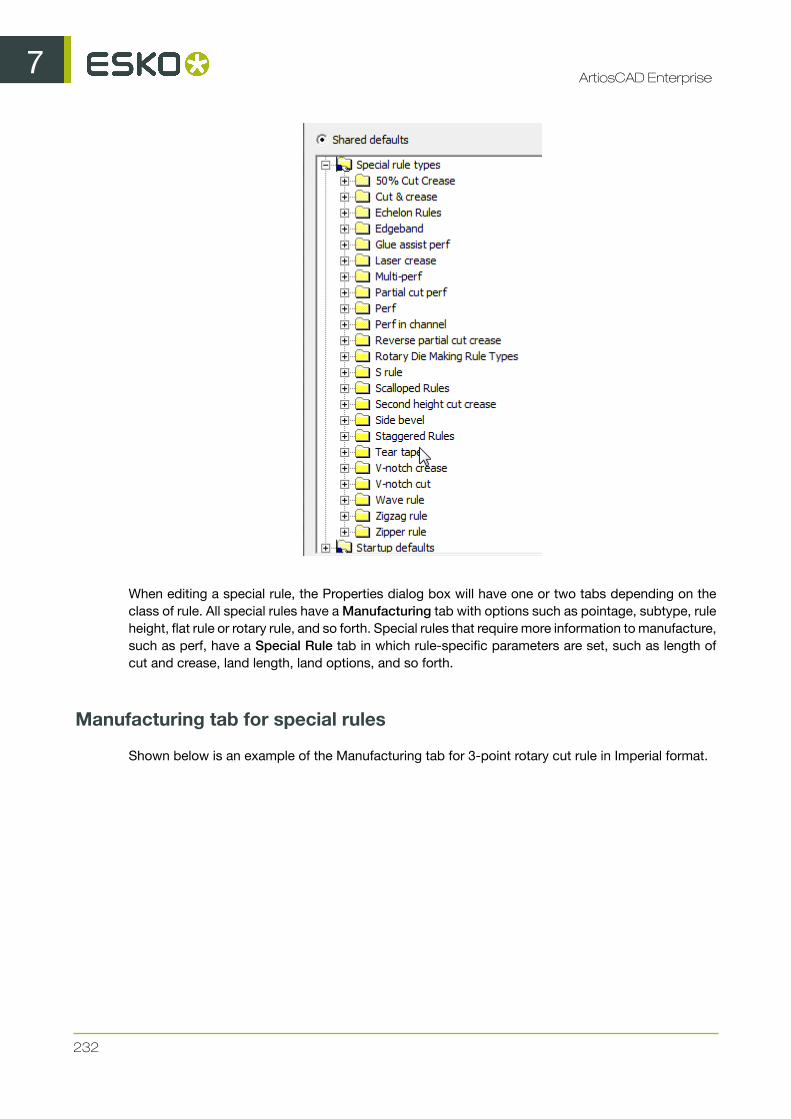
7ArtiosCAD Enterprise
232
When editing a special rule, the Properties dialog box will have one or two tabs depending on theclass of rule. All special rules have a Manufacturing tab with options such as pointage, subtype, ruleheight, flat rule or rotary rule, and so forth. Special rules that require more information to manufacture,such as perf, have a Special Rule tab in which rule-specific parameters are set, such as length ofcut and crease, land length, land options, and so forth.
Manufacturing tab for special rules
Shown below is an example of the Manufacturing tab for 3-point rotary cut rule in Imperial format.

7ArtiosCAD Enterprise
233
Pointage sets the pointage of the rule. You can either select a value from the drop-down list boxor type your own.
Subtype sets the subtype of the rule. The subtype is used to configure specific manufacturing optionsin a CAM Tooling Setup.
Rule height and Rule Cost set the height and cost of the rule respectively. This information is usedin line type legends and DDES-3 files only.
The text in the Rule Label field is printed when rule labels are enabled in the View Mode dialog boxor in Outputs.
The Generic Type field is used to determine if more configuration options are needed on a secondtab. For example, the cut and crease generic types do not require more configuration information,but the perfs and cut & crease types do.
The options in the Die Representation group determine how the rule is manufactured. Use pointagesets the slot width to the pointage * 0.014 inches. Design sets the slot in the die so that it followsthe design of the special rule, such as waves in a wave rule. The slot width is the pointage * 0.014inches. Slot lets you specify a custom slot width independent of the pointage.
Bridge formula for the rule path tells the rule which bridging formula to use. Bridge on teeth controlswhether or not the rule has teeth, and what the tooth size, tab width, and which bridging formulato use.
Nominal tooth spacing refers to the customary size of the teeth on rotary rule. The Actual spacing isthe distance between each tooth measured around the cylinder at cylinder level. The easiest way tomeasure this value is to mark off the distance between 10 teeth on a cylinder, and measure aroundthe cylinder with an accurate tape measure, making sure to use the same point for the start and end.Divide by 10 to get the Actual spacing.
The Cylinder diameter is the cylinder for which this rule was made. It is used ONLY to compute toothspacing when other-sized cylinders use this rule.

7ArtiosCAD Enterprise
234
If you enter a cylinder diameter and an actual spacing value, Esko ArtiosCAD can compute the toothspacing when other die cylinders are used. This means that you do not have to enter separate specialrules for each diameter cylinder!.
Table: Rule Tooth Values
Common cylinderdiameters
Tooth Spacing Result from
Nominal Actual
Inch
21.000 0.500 0.471 Computed
19.1875 0.500 0.469 Rule table
14.125 0.500 0.458 Computed
11.500 0.500 0.450 Computed
10.1875 0.500 0.444 Computed
7.000 0.500 0.423 Computed
Metric
530.00 11.00 10.36 Computed
487.36 11.00 10.31 Rule table
300.00 11.00 9.92 Computed
250.00 11.00 9.73 Computed
The tooth spacing is different for different cylinder diameters because when the rule is bent, it bendsaround the neutral axis. The neutral axis is the point in the rule that neither gets longer nor shorterwhen the rule is bent into a circular arc. The position of the neutral axis will be different for differenttypes of rule. For example, some 6pt or 3pt rule will have the neutral axis a little closer to the topof the rule than simple 3pt rule. This is because the 6pt part is harder to bend than the 3pt parttowards the bottom. Of course, the bottom of the rule has teeth cut out of it, so it is very easy tobend. Normal 3pt toothed rule would have the neutral axis about half way between the top of thetooth notch and the top of the rule.
As the cylinder diameter gets smaller, the teeth will get closer together, but the distance along theneutral axis will remain unchanged. The position of the neutral axis can be computed from the valuesgiven. It can then be used to calculate the tooth spacing for any diameter.
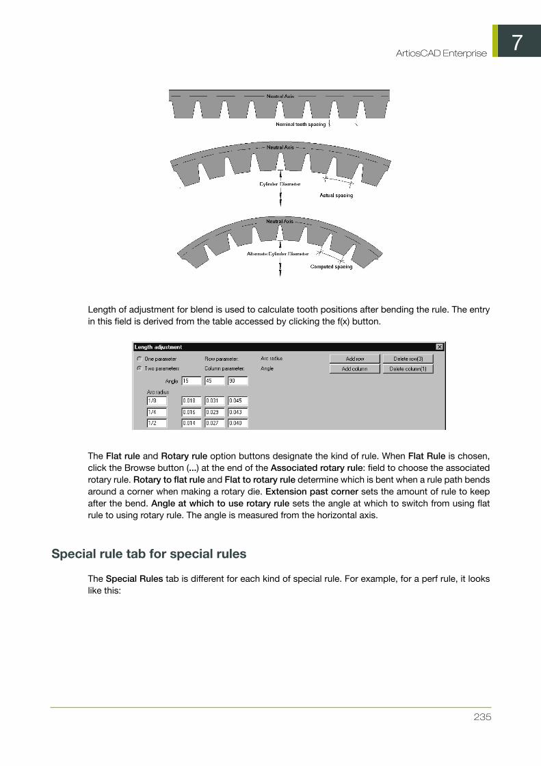
7ArtiosCAD Enterprise
235
Length of adjustment for blend is used to calculate tooth positions after bending the rule. The entryin this field is derived from the table accessed by clicking the f(x) button.
The Flat rule and Rotary rule option buttons designate the kind of rule. When Flat Rule is chosen,click the Browse button (...) at the end of the Associated rotary rule: field to choose the associatedrotary rule. Rotary to flat rule and Flat to rotary rule determine which is bent when a rule path bendsaround a corner when making a rotary die. Extension past corner sets the amount of rule to keepafter the bend. Angle at which to use rotary rule sets the angle at which to switch from using flatrule to using rotary rule. The angle is measured from the horizontal axis.
Special rule tab for special rules
The Special Rules tab is different for each kind of special rule. For example, for a perf rule, it lookslike this:
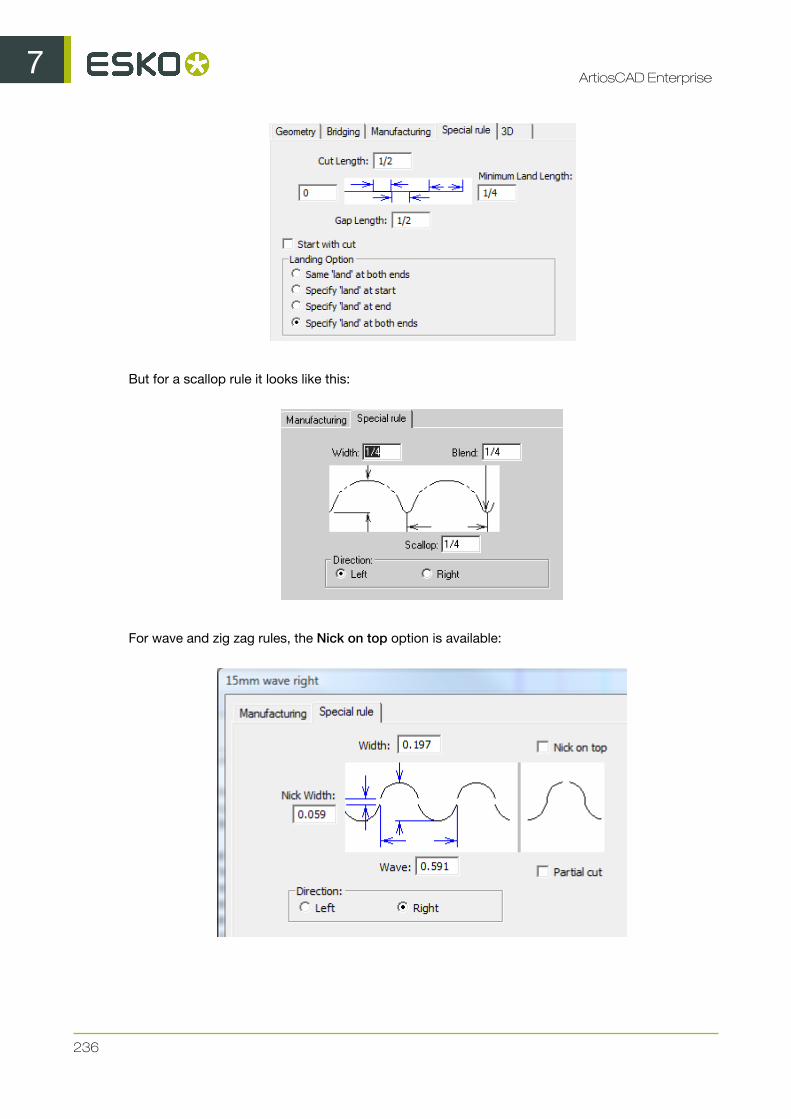
7ArtiosCAD Enterprise
236
But for a scallop rule it looks like this:
For wave and zig zag rules, the Nick on top option is available:

7ArtiosCAD Enterprise
237
You probably already know the parameters for the rule you are configuring; enter the values andclick OK to save the changes to the special rule and return to Defaults, or click Cancel to discardthe changes.
Multi-Perf Overview
Multi-perf is perforation rule with a repeating pattern of differently sized teeth and gaps. Shown beloware some examples of multi-perf rules.
The pattern for the multi-perf is defined in a workspace.
Save your pattern definition workspace to ServerLib (conventional version) or the ServerLib folderin the Shared Defaults Project (Enterprise version).
Designing a multi-perf pattern
In each pattern definition workspace, design a combination of horizontally aligned cuts, creases, andgaps that define the pattern. You can add optional vertical annotation lines marking the land lengthand the ends of the pattern. Shown below are sample patterns.

7ArtiosCAD Enterprise
238
Special rule type Perf pattern workspace
1/8 1/8 perf-in-crease
1/4 1/4 perf crease
1/4 1/4 3/4 perf
1/8 1/8 3/8 perf
Multi-perf1
The vertical annotation line in the 1/8 1/8 perf-in-crease example instructs ArtiosCAD to treat thecrease as the land. For the 1/4 1/4 3/4 perf, the land is the space between the two annotation lines,which ArtiosCAD uses to center the perf pattern along design lines. The Multi-perf1 pattern is toolong for a land, so the vertical annotation line marks the end of the pattern.
Use the following line types when designing your own pattern defintion workspace:
• Cut• Partial cut• Reverse partial cut• Crease• Second height crease• Matrix crease
Defining the land
An annotation line in the middle of a pattern marks the right end of a land.
If the pattern has a land, ArtiosCAD centers the perf pattern on the line with the same land at bothends. Shown below is an example of how the pattern is centered on lines of different length.
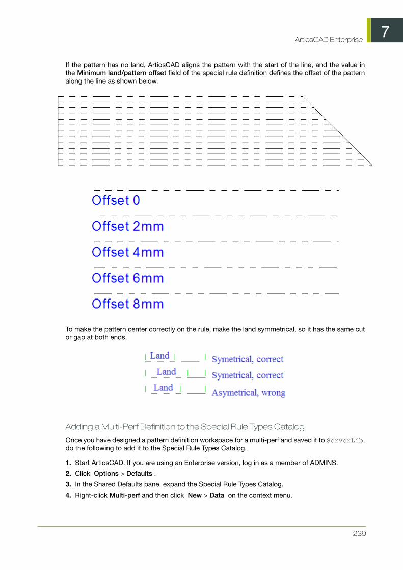
7ArtiosCAD Enterprise
239
If the pattern has no land, ArtiosCAD aligns the pattern with the start of the line, and the value inthe Minimum land/pattern offset field of the special rule definition defines the offset of the patternalong the line as shown below.
To make the pattern center correctly on the rule, make the land symmetrical, so it has the same cutor gap at both ends.
Adding a Multi-Perf Definition to the Special Rule Types Catalog
Once you have designed a pattern definition workspace for a multi-perf and saved it to ServerLib,do the following to add it to the Special Rule Types Catalog.
1. Start ArtiosCAD. If you are using an Enterprise version, log in as a member of ADMINS.
2. Click Options > Defaults .
3. In the Shared Defaults pane, expand the Special Rule Types Catalog.
4. Right-click Multi-perf and then click New > Data on the context menu.

7ArtiosCAD Enterprise
240
5. Enter a name for the new multi-perf type and press Enter.
6. On the Manufacturing tab of the special rule type dialog box, select Multi-perf from the Generictype drop-down list box.
7. On the Special rule tab of the special rule type dialog box, enter or browse for the pattern definitionfile. Enter a value in the Minimum land/pattern offset field if the pattern definition workspacedoes not have a land defined.

7ArtiosCAD Enterprise
241
8. Click OK to save the new multi-perf catalog entry.
9. Save and exit Defaults as usual.
Edge band and Tear Tape Overview
Edge band is a cover that hides the edge of thick material, such as Re-board®, usually used fordisplays.

7ArtiosCAD Enterprise
242
Tear tape is the thin plastic strip on the inside of box-opening features.
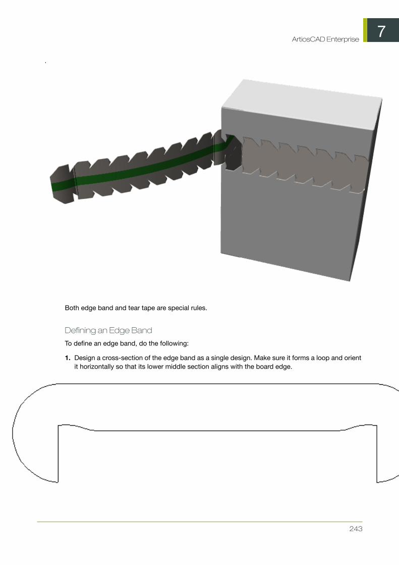
7ArtiosCAD Enterprise
243
Both edge band and tear tape are special rules.
Defining an Edge Band
To define an edge band, do the following:
1. Design a cross-section of the edge band as a single design. Make sure it forms a loop and orientit horizontally so that its lower middle section aligns with the board edge.

7ArtiosCAD Enterprise
244
2. Copy the cross-section workspace to ServerLib.
3. In Defaults, add a new entry to the Edgeband folder of the Special Rule Types catalog by right-clicking it and then clicking New > Data on the context menu.
4. On the Manufacturing tab, set its Generic type to Edge band.
5. On the Special rule tab, enter the cross-section workspace's name or browse for it.
6. Click Select Color to set the color of the edge band.
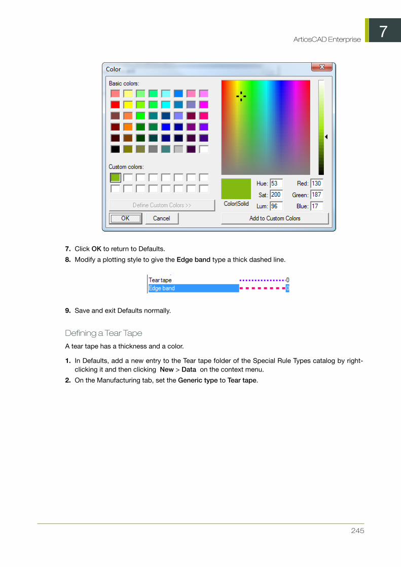
7ArtiosCAD Enterprise
245
7. Click OK to return to Defaults.
8. Modify a plotting style to give the Edge band type a thick dashed line.
9. Save and exit Defaults normally.
Defining a Tear Tape
A tear tape has a thickness and a color.
1. In Defaults, add a new entry to the Tear tape folder of the Special Rule Types catalog by right-clicking it and then clicking New > Data on the context menu.
2. On the Manufacturing tab, set the Generic type to Tear tape.

7ArtiosCAD Enterprise
246
3. On the Special rule tab, enter a value in the Width field.
4. Click Select Color to set the color of the tear tape.
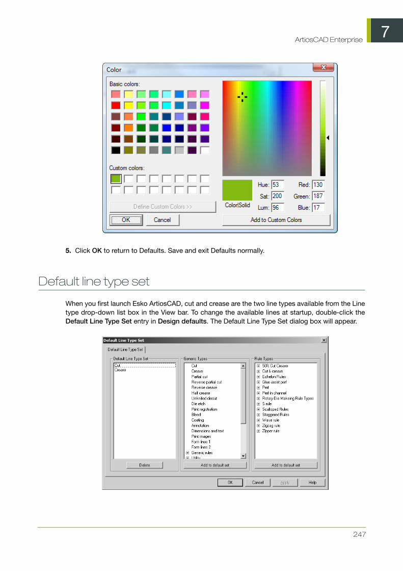
7ArtiosCAD Enterprise
247
5. Click OK to return to Defaults. Save and exit Defaults normally.
Default line type set
When you first launch Esko ArtiosCAD, cut and crease are the two line types available from the Linetype drop-down list box in the View bar. To change the available lines at startup, double-click theDefault Line Type Set entry in Design defaults. The Default Line Type Set dialog box will appear.
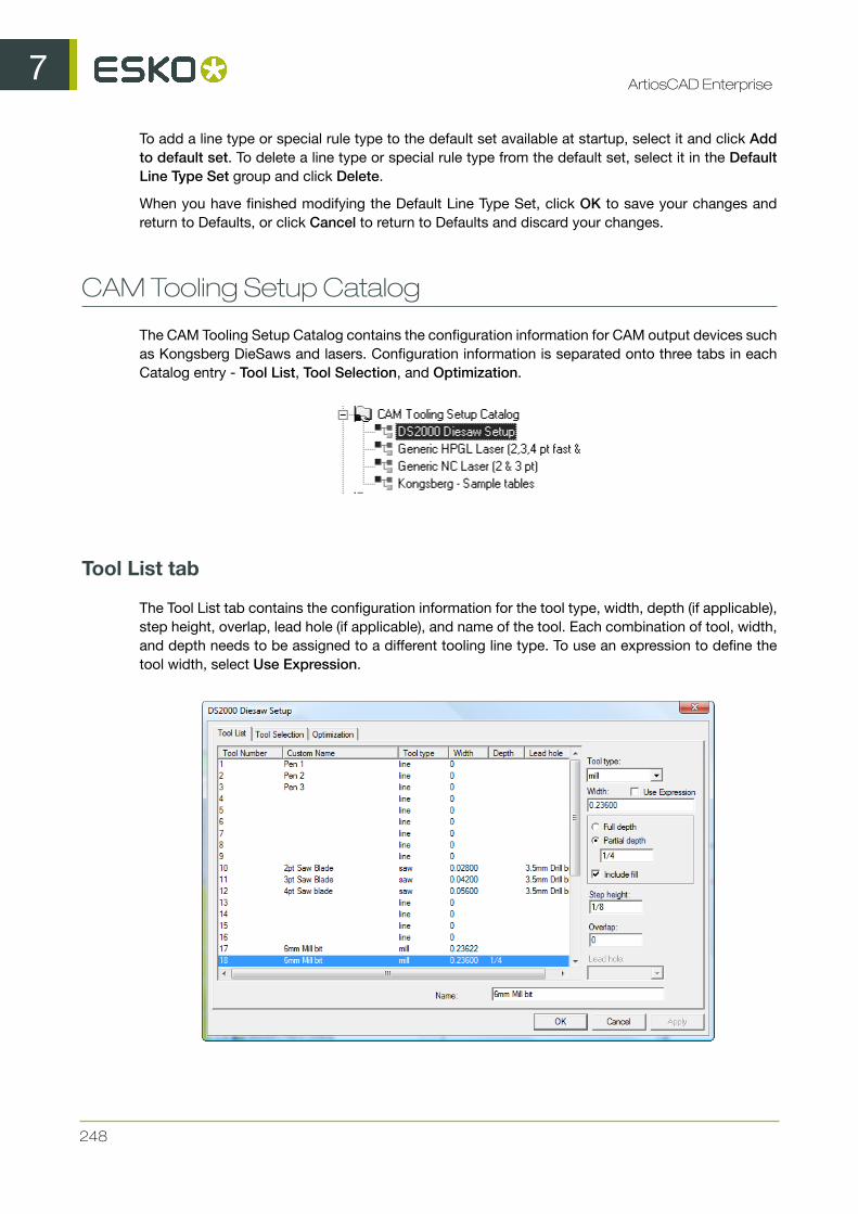
7ArtiosCAD Enterprise
248
To add a line type or special rule type to the default set available at startup, select it and click Addto default set. To delete a line type or special rule type from the default set, select it in the DefaultLine Type Set group and click Delete.
When you have finished modifying the Default Line Type Set, click OK to save your changes andreturn to Defaults, or click Cancel to return to Defaults and discard your changes.
CAM Tooling Setup Catalog
The CAM Tooling Setup Catalog contains the configuration information for CAM output devices suchas Kongsberg DieSaws and lasers. Configuration information is separated onto three tabs in eachCatalog entry - Tool List, Tool Selection, and Optimization.
Tool List tab
The Tool List tab contains the configuration information for the tool type, width, depth (if applicable),step height, overlap, lead hole (if applicable), and name of the tool. Each combination of tool, width,and depth needs to be assigned to a different tooling line type. To use an expression to define thetool width, select Use Expression.

7ArtiosCAD Enterprise
249
To set up the tool list, choose the tool number to modify and then set the tool type. Set the availableoptions and enter a name for the tool in the Name: field.
The table below explains the function of each tool type.
Table: Tool Types, Their Properties, And Intended Uses
Tool type Properties Description Intended uses
line none Uses the original lines;performs no processing.
Drawing with a pen.
slot Width - effective width of the tool
Overlap - overlap between multiplepasses of the tool. Available whenPartial Depth is selected.
Makes a slot of a definedwidth. Will envelope if theslot width is wider thanthe tool width.
Laser-cut slot for arule in a dieboard
drill Width - effective diameter of thedrill
Full Depth - Depth is the full depthvalue, defined in the output
Partial Depth - Depth is defined inthe CAM setup
Drills a hole at a pointwhose diameter isdefined by the width inthe CAD setup.
Mounting holes,leader holes
any drill Full Depth - Depth is the full depthvalue, defined in the output
Partial Depth - Depth is defined inthe CAM setup
Drills a hole at a pointwhose diameter isdefined by the diameterof the circle in theworkspace.
Mounting holes
counter drill Width - effective diameter of thedrill
Full Depth - Depth is the full depthvalue, defined in the output
Partial Depth - Depth is defined inthe CAM setup
Drills a hole with acounter sink drill, sameas the drill tool type,but sends differentcommands to theKongsberg driver.
Countersink holes.
mill Width - Effective diameter of thetool.
Full depth - Depth is the full depthvalue, defined in the output.
Partial depth - Depth is defined inthe CAM setup.
Include fill (off) - One pass insideor outside the outline.
Include fill (on) - Multiple loops,starting in the middle of a hole, andworking outwards
Mills inside or outside theoutline which is usually aloop.
Holes in a dieboardthat are too small tosaw; the dieboardalignment notch.
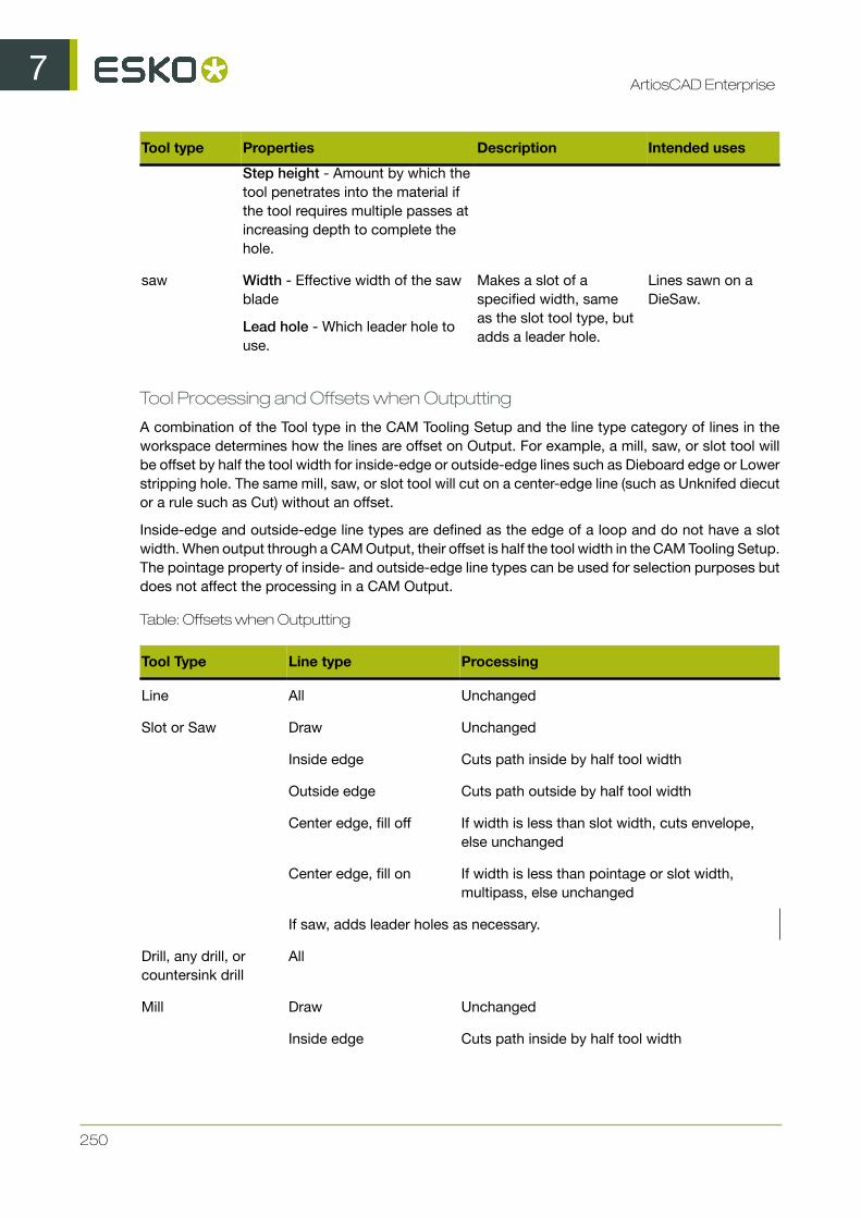
7ArtiosCAD Enterprise
250
Tool type Properties Description Intended uses
Step height - Amount by which thetool penetrates into the material ifthe tool requires multiple passes atincreasing depth to complete thehole.
saw Width - Effective width of the sawblade
Lead hole - Which leader hole touse.
Makes a slot of aspecified width, sameas the slot tool type, butadds a leader hole.
Lines sawn on aDieSaw.
Tool Processing and Offsets when Outputting
A combination of the Tool type in the CAM Tooling Setup and the line type category of lines in theworkspace determines how the lines are offset on Output. For example, a mill, saw, or slot tool willbe offset by half the tool width for inside-edge or outside-edge lines such as Dieboard edge or Lowerstripping hole. The same mill, saw, or slot tool will cut on a center-edge line (such as Unknifed diecutor a rule such as Cut) without an offset.
Inside-edge and outside-edge line types are defined as the edge of a loop and do not have a slotwidth. When output through a CAM Output, their offset is half the tool width in the CAM Tooling Setup.The pointage property of inside- and outside-edge line types can be used for selection purposes butdoes not affect the processing in a CAM Output.
Table: Offsets when Outputting
Tool Type Line type Processing
Line All Unchanged
Slot or Saw Draw Unchanged
Inside edge Cuts path inside by half tool width
Outside edge Cuts path outside by half tool width
Center edge, fill off If width is less than slot width, cuts envelope,else unchanged
Center edge, fill on If width is less than pointage or slot width,multipass, else unchanged
If saw, adds leader holes as necessary.
Drill, any drill, orcountersink drill
All
Mill Draw Unchanged
Inside edge Cuts path inside by half tool width
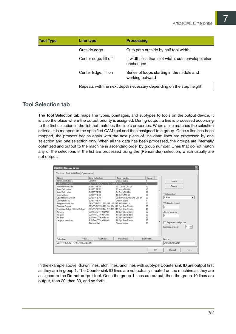
7ArtiosCAD Enterprise
251
Tool Type Line type Processing
Outside edge Cuts path outside by half tool width
Center edge, fill off If width less than slot width, cuts envelope, elseunchanged
Center Edge, fill on Series of loops starting in the middle andworking outward
Repeats with the next depth necessary depending on the step height
Tool Selection tab
The Tool Selection tab maps line types, pointages, and subtypes to tools on the output device. Itis also the place where the output priority is assigned. During output, a line is processed accordingto the first selection in the list that matches the line's properties. When a line matches the selectioncriteria, it is mapped to the specified CAM tool and then assigned to a group. Once a line has beenmapped, the process begins again with the next piece of line data; lines are processed by oneselection and one selection only. When all the data has been processed, the groups are internallyoptimized and output to the machine in ascending order by group number. Lines that do not matchany of the selections in the list are processed using the (Remainder) selection, which usually arenot output.
In the example above, drawn lines, etch lines, and lines with subtype Countersink ID are output firstas they are in group 1. The Countersink ID lines are not actually created on the machine as they areassigned to the Do not output tool. Once the group 1 lines are output, then the group 10 lines areoutput, then 20, then 30, and so forth.

7ArtiosCAD Enterprise
252
The Types, Subtypes, and Pointages buttons lead to dialog boxes where you can select exactlywhat will be output in this selection. These dialog boxes are similar to those used for selections inplotting styles.
Note: The Text and dimensions checkbox in Types > Design only applies to text and dimensionsthat have not had a color applied. Those with a color applied are considered graphics and are notoutput to CAM devices.
By default, all items are turned on when you enter the dialog box for the first time. Click InvertSelection to clear each checkbox. Clicking Select All selects all the items in the list. If you makeselections other than having all selected or having none selected, the base Esko ArtiosCAD syntax isshown in the field beneath the list. When you have finished selecting, click OK to return to the Setupdialog box saving your changes or Cancel to return, ignoring your changes.
The Slot Width button opens the Slot Width dialog box in which you can specify a minimum slotwidth and a maximum slot width. Any line with a slot width between those values will be selected.#I or #M is automatically appended to the slot width selection to allow for conversion between unitsof measurement.

7ArtiosCAD Enterprise
253
The up and down arrows to the side of the selection list move the selected entry either up or downin the list depending on which button is clicked.
Insert adds a new entry above the current selection; Delete deletes the current selection. The(Remainder) selection may not be deleted.
The Tool number: field selects the CAM tool to map to the line selection. Entries for this drop-downlist come from the Tool List tab. The Size only tool is meant to be used for easier registration. Linessent to the Size only tool show in a preview and are used to calculate the output size, but are onlyactually output when outputting to a layer.
The Width adjustment: field allows you to add to the slot width that is cut. Usually the slot width isdefined by the slot width of the rule if so defined or by the pointage of the rule. However, the preferredway to adjust the slot width for laser output is to use a special rule with a defined slot width.
The Group number: defines which group the selected lines are put into. Group 1 is output first, thengroup 2, group 3, and so on.
If the Separate bridge tool checkbox is checked, another line is added beneath the selection in thelist to allow the processing of bridges for that selection to be defined separately. This means thatbridges can be made with a different tool.
The Number of tools field allows for more than one tool to manufacture the lines selected by aselection criteria line. Configure the extra lines as you would any of the other selection criteria lines.
Enter the desired name for the selection criteria line in the Name: field.
Note: Wave rules with nick width of 0 are treated as cuts and processed by the GENTYPE 1 toolselection.
Optimization tab
The Optimization tab controls the internal optimization of the groups of output. Optimizing is on forall groups by default.

7ArtiosCAD Enterprise
254
To turn off optimization for a group, select it and clear the Optimize checkbox. To turn it on, selectit and check the Optimization checkbox.
Separate subroutine controls if each group will be in its own subroutine. If the box is checked, theselected group is independent. If the box is clear, the selected group shares the same subroutineas the previous group.
CAM Output of Rubber Sheets
A CAM Tooling Setup catalog entry should be set up for the following line types for output to (forexample) a waterjet rubber-cutting machine.
Table: Rubber CAM tooling setup
Line type Name Usage
Type 220 Rubber inside edge If using different logical tools for the inside edge and theoutside edge. Otherwise make them the same.
Type 221 Rubber outline
Type 222 Rubber name Cuts the numbers in the rubber pieces, if Show elementnumbers is selected on the Processing page in theOutput.
Type 97 Usable limit of sheet If required, cuts the outline of the sheet area used.
Type 98 Sheet size Map to Size only to see the sheet size.
Shown below is an example CAM Tooling Setup catalog entry.

7ArtiosCAD Enterprise
255
Specifying a rotary die in a press definition
When you first create a press, Esko ArtiosCAD assumes it is flat by default. To specify a rotarydieboard configuration, double-click the Rotary Shrink Stretch Factors entry in the parameter setfor that press.
In the Rotary Shrink Stretch Factors dialog box, check the Rotary Dieboard checkbox and fill in thevalues for the Wood Thickness, Cylinder Diameter, Design to Wood Level Shrink, and Cylinder toWood Level Stretch fields with the proper values.
Once the fields are complete, click OK to return to Defaults or click Cancel to cancel.

7ArtiosCAD Enterprise
256
Hole Catalog
Holes are used in manufacturing to attach the boards to the presses. There are three types of holes:General holes, Drill holes, and Oblong holes. As holes utilize subtypes, configure subtypes beforeadding holes.
Adding a hole to the Hole Catalog
To add a hole, right-click Hole Catalog, and click New > Data from the context menu. Give thenew hole a name and double-click its entry to open its Properties dialog box. Edit the values asappropriate. The Diameter Y field is available when the hole type is set to Oblong Hole. CounterSink Diameter is available only when the Counter Sink checkbox is checked. Set the Subtype fieldsas appropriate.
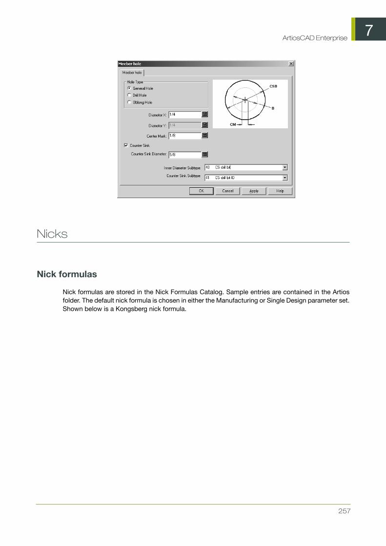
7ArtiosCAD Enterprise
257
Nicks
Nick formulas
Nick formulas are stored in the Nick Formulas Catalog. Sample entries are contained in the Artiosfolder. The default nick formula is chosen in either the Manufacturing or Single Design parameter set.Shown below is a Kongsberg nick formula.

7ArtiosCAD Enterprise
258
The five placement buttons at the upper left of the tab set the default placement option for nickswhen the Add Nick tool is activated.
Offset sets the nicks so that they offset from the nearest endpoint of the line or arc.
Center places the nick in the center of a line or arc.
Anywhere places the nick at the point you click.
Fill line fills the line or arc with evenly spaced nicks.
At the end of the line places the nick at the end of a line.
The fields in the Nick sizes:, Offsets:, and Between nicks: columns set the values for the drop-downlist boxes when the Add Nick tool is activated.
The Number field sets the default number of nicks to add when the Add Nick tool is activated.

7ArtiosCAD Enterprise
259
Set the default nick size to use by entering either an absolute value or a formula in the Default nicksize: field. If no default size is set, the Add Nick tool and the Bridging properties dialog box defaultto the first defined size.
Nick styles
Esko ArtiosCAD can represent nicks as a single line, a double line, a text label, or as any workspaceyou designate. You can configure different ways for nicks to be represented based on their size. NickStyles are configured in the Nick Styles Catalog. You can either modify the default nick styles in theArtios folder or you can create your own. A sample nick style is shown below.
By default, a newly-created nick style has only one entry in it. This one entry defines how all nicksare shown.

7ArtiosCAD Enterprise
260
Insert and Delete add conditions for nick sizes. Select an entry in the list before clicking either.
The option buttons in the Nick Output Type group - Single line, Pair of lines, Text, and Workspace- control the type of nick made.
The values in the Start and End fields set the length of the line(s) representing the nick. The valuein the Start field sets the distance between the line containing the nick and the start of the linerepresenting the nick. Use a negative offset to have the nick representation cross the design line.The value in the End field sets the distance between the line containing the nick and the end of theline representing the nick. The line(s) representing the nick are always drawn perpendicular to theline containing the nick.
The Workspace name: field is available only when the Nick Output Type is set to Workspace. Inthis field, enter the name of the workspace to use to indicate a nick, or use the Browse button (...)to browse for the nick workspace. The workspace must have the center of the nick representationas the origin of the workspace (where the two construction line axes meet). The line type used todraw the nick workspace is ignored; the nick is drawn as a nick line type. Anything other than linesand arcs in the nick workspace is ignored.
Add the size of the nick as text to the nick by using the Text nick output type in a selected Nick Stylein Defaults. Set the size of the text in the Text Size: drop-down list box, which is available only whenthe Nick output type is set to Text.
When two nicks are close together, and the nicks are represented by workspaces, if the twoworkspaces would overlap, the second nick is shown as a line.
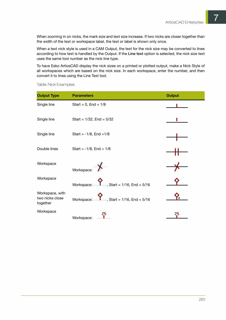
7ArtiosCAD Enterprise
261
When zooming in on nicks, the mark size and text size increase. If two nicks are closer together thanthe width of the text or workspace label, the text or label is shown only once.
When a text nick style is used in a CAM Output, the text for the nick size may be converted to linesaccording to how text is handled by the Output. If the Line text option is selected, the nick size textuses the same tool number as the nick line type.
To have Esko ArtiosCAD display the nick sizes on a printed or plotted output, make a Nick Style ofall workspaces which are based on the nick size. In each workspace, enter the number, and thenconvert it to lines using the Line Text tool.
Table: Nick Examples
Output Type Parameters Output
Single line Start = 0, End = 1/8
Single line Start = 1/32, End = 5/32
Single line Start = -1/8, End =1/8
Double lines Start = -1/8, End = 1/8
Workspace
Workspace:
Workspace
Workspace: , Start = 1/16, End = 5/16
Workspace, withtwo nicks closetogether
Workspace: , Start = 1/16, End = 5/16
Workspace
Workspace:

7ArtiosCAD Enterprise
262
Output Type Parameters Output
Text Text size in points
When you have finished modifying the nick style, click OK to return to Defaults keeping your changes,or click Cancel to return to Defaults ignoring your changes.
Standard Sheet Layout
Parameters and standard sheet sizes for Standard Sheet Layout are configured in the SheetUtilization catalog in Defaults.
Sheet Layout Parameters
Double-click Sheet Layout Parameters to set the defaults for the trim, gutters, nest types, and otheroptions to use in Standard Sheet Layout as shown below.

7ArtiosCAD Enterprise
263
In the Trim group, the fields set the trim tolerances at the edge of the sheet. Set them to be less thanthe maximum values for the presses used to produce the layout.
Use gutters inserts gutters between designs in the nest when it is checked. When it is clear, thesingle designs touch. The values in the X and Y fields set the gutters in X and Y for the first andsecond rows and columns of single designs in the layout. The values in the X2 and Y2 drop-downlist boxes set the gutters between the second and third rows and columns. These are repeated asappropriate between all the rows and columns in the layout.
In the Nest type group, the checkboxes control the kinds of nests made automatically. Select thecheckboxes next to the type of nests to use; clear those next to undesired nests.
Touch bleed outlines controls whether the designs touch using the bleed outlines or the edges of thedesigns. If Use gutters is enabled in conjunction with Touch bleed outlines, the gutters are insertedbetween the bleed outlines instead of the edges of the designs.
In the Design options group, Allow 90 degree rotation lets designs rotate so they are cross-grain;the sheet grain runs in the longer direction. Maximum allowable reduction is the maximum distancethat could be shaved off each design in order for another row or column to fit on the sheet. If such acutback is possible in each design, a row or column will overlap the edge of the sheet when a layoutis suggested and there will be values in the various Reduction fields of the Sheet Layout Resultsdialog box.

7ArtiosCAD Enterprise
264
Click OK to save the changes, or click Cancel to ignore them and return to Defaults.
Standard Sheet Sizes
Double-click Standard Sheet Sizes to configure the defaults for standard sheets used by StandardSheet Layout.
To use a sheet for possible layout solutions, check its box in the Use column. To disable its use, clearthe checkbox. To toggle the usage of all sheets at once, click All on/off.
The arrows on the side of the dialog box move the currently-selected sheet up and down in the listof sheets. The order of sheets on this tab is the same order used to present layout results.
To edit a sheet, select it, and change the fields in the Edit Sheet Properties group. The fields changeas soon as you click another field
To add a sheet, click Insert, and then edit the fields in the Edit Sheet Properties group. Set thecheckbox in the Use column as desired.
To delete a sheet, select it, and click Delete.
To save the changes to the standard sheets, click OK. To discard the changes and return to Defaults,click Cancel.
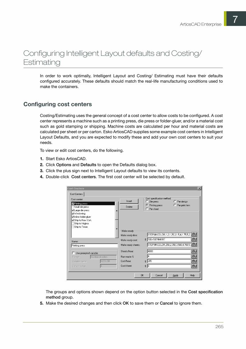
7ArtiosCAD Enterprise
265
Configuring Intelligent Layout defaults and Costing/Estimating
In order to work optimally, Intelligent Layout and Costing/ Estimating must have their defaultsconfigured accurately. These defaults should match the real-life manufacturing conditions used tomake the containers.
Configuring cost centers
Costing/Estimating uses the general concept of a cost center to allow costs to be configured. A costcenter represents a machine such as a printing press, die press or folder-gluer, and/or a material costsuch as gold stamping or shipping. Machine costs are calculated per hour and material costs arecalculated per sheet or per carton. Esko ArtiosCAD supplies some example cost centers in IntelligentLayout Defaults, and you are expected to modify these and add your own cost centers to suit yourneeds.
To view or edit cost centers, do the following.
1. Start Esko ArtiosCAD.2. Click Options and Defaults to open the Defaults dialog box.3. Click the plus sign next to Intelligent Layout defaults to view its contents.4. Double-click Cost centers. The first cost center will be selected by default.
The groups and options shown depend on the option button selected in the Cost specificationmethod group.
5. Make the desired changes and then click OK to save them or Cancel to ignore them.
7ArtiosCAD Enterprise
266
The items in the Cost center dialog are explained in the following list:
Table: Cost Center Dialog Box
Item Explanation
List of cost centers The list of cost centers must be arranged in the order they are used. Theoutput of one cost center is the input to the next. When the checkboxis off, the cost center is an option, available to be selected but is notturned on by default.
Up arrow, down arrow Moves the selected cost center up or down in the list
Name Changes the name of the selected cost center
Insert Inserts a new cost center above the selected one.
Delete Deletes the selected cost center
Per sheet The cost center applies to sheets, for example a sheeter.
Printing press Works the same as a sheet cost center, but identifies the printing presscost center to be reported separately.
Die press Works the same as a sheet cost center, but identifies the die press costcenter to be reported separately.
Per design Cost center such as a folder-gluer, where make ready is needed for eachdifferent design, and a smaller make ready is needed for a different printitem of the same design.
Per print item Cost center such as windowing, if the windows were different on eachprint item. There is a separate make ready for each print item.
Use prompted variable Only if a variable is to be associated with this cost center. For exampleFGD = folder-gluer degree of difficulty, or NCOL2 = number of colorsfor a second printing press, see note. The variable is added to thePrompted Variables tab of the Quantities and Costs dialog if this costcenter is included.
Prompt Prompt/description of this variable
Variable name Name of the prompted variable to be used in expressions. A promptedvariable can be used in expressions such as make ready and speed,inside the PVAR function. For example, the make ready time of theprinting press is defined to be 1+PVAR(NCOLOR)/2, that is, 1 hour plus1/2 hour for each color. The name of the variable can use up to 6 lettersand digits and must start with a letter.
Default value Default value of the prompted variable
Make ready time Expression for the make ready time in hours
Sheets/hour The normal speed of the machine when it has reached its optimal speed.

7ArtiosCAD Enterprise
267
Item Explanation
The theory is that the machine runs for a while at a slower speed for thefirst few sheets while it is brought into alignment, and then the speed isincreased to its optimal speed. For a multi-step ramp up in speed, usethe SPEEDSTEP function.
Run waste % The percent waste while running. A machine such as a printing pressmay periodically go out of alignment and waste some sheets.
Cost/hour Cost of the machine per hour while running. Does not include the cost ofthe machine during make ready, which is separate.
Cost/sheet Additional material cost per sheet apart from the board cost. If the costspecification method is per print item, this label changes to Cost/carton,for example the cost of a window in each carton.
Opens an expression configuration dialog box. See the followingsection.
Changing Cost Center expressions
Clicking the f(x) button in a cost center expression leads to an expression configuration dialog box.For example, clicking f(x) for the Make ready time expression:
(STEP(#NCOLOR,1,2,1.25,3,1.5,4,1.75,5,2.25,6, 2.75,7,3,8,3.5))
leads to:
This dialog box lets you choose how the value for the selected field is determined - by a table ofconditions or by an expression; in this example, the method is set to table. Only when the methodis set to table is there a Table tab in the dialog box.
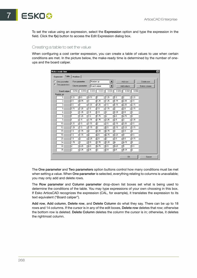
7ArtiosCAD Enterprise
268
To set the value using an expression, select the Expression option and type the expression in thefield. Click the f(x) button to access the Edit Expression dialog box.
Creating a table to set the value
When configuring a cost center expression, you can create a table of values to use when certainconditions are met. In the picture below, the make-ready time is determined by the number of one-ups and the board caliper.
The One parameter and Two parameters option buttons control how many conditions must be metwhen setting a value. When One parameter is selected, everything relating to columns is unavailable;you may only add and delete rows.
The Row parameter and Column parameter drop-down list boxes set what is being used todetermine the conditions of the table. You may type expressions of your own choosing in this box.If Esko ArtiosCAD recognizes the expression (CAL, for example), it translates the expression to itstext equivalent (“Board caliper”).
Add row, Add column, Delete row, and Delete Column do what they say. There can be up to 18rows and 14 columns. If the cursor is in any of the edit boxes, Delete row deletes that row; otherwisethe bottom row is deleted. Delete Column deletes the column the cursor is in; otherwise, it deletesthe rightmost column.

7ArtiosCAD Enterprise
269
The f(x) button for the Sheets/hour field leads to an expression configuration dialog box which hasthree entries which behave exactly as those described above.
Modifiers for cost center expressions
A modifier allows adjustments to be made to an expression in certain situations. For example, amodifier could use this logic: if the caliper is 0.016” or less, add 10%. Modifiers can do the followingto the output of the expression:
• Add a percentage• Subtract a percentage• Add a value• Subtract a value• Multiply by a value• Divide by a value• Set a minimum value• Set a maximum value
To add a modifier to a cost center expression, do the following:
1. Click the f(x) button for that expression and then click the Modifiers tab.
2. Click Add to add a modifier. A list of modifiers appears:

7ArtiosCAD Enterprise
270
3. Choose a modifier to add to the expression (for this example, choose Large caliper) and clickOK. Esko ArtiosCAD will return to the Modifiers dialog box.
4. Click Edit to open the Edit Modifier dialog box.

7ArtiosCAD Enterprise
271
The option buttons in the Condition type group let you quickly change the condition with a singlemouse click. If you select No condition, the Limit value and Condition fields are unavailable.Changing the condition type option button automatically updates the expression in the Conditionfield. The Condition type and the Limit value combine into the Condition.
The option buttons in the Modification group determine the operation of the modifier. The amountof the modification is set in the Modification value field.
5. Click OK to accept the changes to the modifier or Cancel to ignore them. Esko ArtiosCAD willreturn to the expression configuration dialog box.
Notes on Intelligent Layout Defaults
Most defaults have the option of User defaults overriding Shared defaults. This does not work wellfor Intelligent Layout because the cost centers from Shared Defaults and User Defaults are mixedtogether. We recommend that you only use Shared Defaults for Intelligent Layout.
The order of the cost centers is important. The Per design and Per print item cost centers must beafter the printing press and the die press.
If you set up a cost center with a prompted variable that has a default value, for example a printingpress with 2 colors, and then want to run a layout with three colors, your first impulse might be todouble-pass the sheet and use the cost center twice. This approach, however, will result in 4 colorsbeing used in the calculations. Make sure to set up a cost center with prompted variables that havedefaults specific for each case you may encounter.
Overview: Setting up a multi-color printing press cost center using atable
The following overview illustrates how to set up a cost center containing variable information. Weare going to set up the following information:
Number of colors 2 3 4 5 6 7 8
Make ready time in hours 1.5 1.75 2.0 2.5 2.75 3.5 4.0
Note that you must enter time in hours, not hours:minutes. For example, 2 hours 45 minutes isrepresented as 2.75 hours.
1. Start Esko ArtiosCAD.2. Click Options and then click Defaults to open the Defaults dialog box.3. Click the plus sign next to Intelligent Layout defaults to view its contents.4. Double-click Cost centers. The first cost center will be selected by default.5. Click Insert to create a new cost center called New cost center.6. Change the name in the Name: field from New cost center to My 8 color press.7. Set the Cost specification method to Printing press.
The Intelligent Layout Defaults dialog should look as follows:

7ArtiosCAD Enterprise
272
8. Click f(x) at the end of the Make ready time: field to set up a table of conditions for the numberof colors. The expression configuration dialog box appears:
9. Click the Table option button in the Make ready time group.10.Click the Table tab.
11.Select One parameter and choose Number of colors for the Row parameter.

7ArtiosCAD Enterprise
273
12.Enter 2 and 1.5 in the first and second fields, respectively, under Number of colors. EskoArtiosCAD will change the 1.5 into 1+1/2.
13.Click Add row. Enter 3 and 1.75 in the first and second fields of the new row.14.Repeat for the rest of the values in the table.15.When the table is complete it should look like this:
16.Click OK to finish configuring the table for the make ready time, and proceed to configuring therest of the cost center.
Useful Functions for Cost Center Expressions
STEP(variable, value1, limit1, value2, limit2,..., limitn, valuen)
Returns value1 when variable < limit1
value2 when limit1 <= variable < limit2
value3 when limit2 <= variable < limit3
...
valuen when limitn <= variable
The STEP function and all its variations must have an even number of parameters, at least 4.

7ArtiosCAD Enterprise
274
Note that we would not recommend that a step function be used for the speed of a machine becausethe run time of a machine using a step function like this would have discontinuities in its run time:
STEPUP(variable, value1, limit1, value2, limit2, ... , limitn, valuen)
Same as STEP except < and <= are reversed:
Returns: value1 when variable <= limit1
value2 when limit1 < variable <= limit2
...
valuen when limitn < variable
LINESTEP(variable, value1, limit1, value2, limit2, ..., limitn, valuen)
As a more sensible alternative to the STEP function for the speed of a machine, this function does alinear interpolation between data points, and avoids the discontinuities in the STEP function.
Returns: value1 when variable <= limit1
Interpolation between value1 and value2 when limit1 <= variable <= limit2
Interpolation between value2 and value3 when limit2 <= variable <= limit3
...
valuen when variable >= limitn

7ArtiosCAD Enterprise
275
Note that to prevent a discontinuity at the last limit, the last two values should be the same, or thelast value might be an expression.
SPEEDSTEP(#RUN,speed1,run1,speed2,run2, ..., runn, speedn)
The SPEEDSTEP function is an alternative for the speed of a machine (depends on how the speedis specified). The machine runs at speed1 for the first run1 sheets, runs at speed speed2 up to a runlength of run2, and so on, and runs at speed speedn after the run length reaches runn. The functionreturns an average speed of the machine given the run length.
List of functions for configuring cost centers
This list of functions is accessible from the Cost Centers dialog box by clicking f(x) and then InsertLibrary Function.
Table: Functions for configuring cost centers
Function Description
#SHTSIZEX Sheet size X, current units (inches or mm).
#SHTSIZEY Sheet size Y, current units (inches or mm).
#SHTSIZEWG Sheet size with grain, current units (inches or mm).
#SHTSIZEXG Sheet size cross grain, current units (inches or mm).
#CUTSIZEX Knife-to-knife X of designs in the layout, in current units (inches ormm).
#CUTSIZEY Knife-to-knife Y of designs in the layout, in current units (inches ormm).
#MANSIZEX Design blank size X (manufacturing lines), in current units (inches ormm) of the current design. If sheet cost center, of the first design.
#MANSIZEY Design blank size Y (manufacturing lines), in current units (inches ormm) of the current design. If sheet cost center, of the first design.
#MANSIZEWG Design blank size with grain (manufacturing lines), in current unitsof the current design. If sheet cost center, of the first design.
#MANSIZEXG Design blank size cross grain (manufacturing lines), in current unitsof the current design. If sheet cost center, of the first design.
#AREA Area of design ignoring holes (zero if area fails) in current units(square inches or square mm) of the current design. If sheet costcenter, of the first design.
7ArtiosCAD Enterprise
276
Function Description
#AREAH Area of design minus holes (zero if area fails) in current units(square inches or square mm) of the current design. If sheet costcenter, of the first design.
#RUN (In the Intelligent Layout Parameters dialog). Run length for this costcenter/item in number of sheets or number of cartons.
(In a form or OCX control). Run length of the first cost center,usually the printing press.
#NUPD (Design, item cost center) How many of this design on the sheet(Sheet cost center) 0
#NUPP (Item cost center) How many of this print item on the sheet (Sheetor design cost center) 0
#NUP Total number of designs on the sheet
#MKRT Make ready time for this cost center/item
#MKRTA (Design cost center) Make ready time for this cost center/item foradditional items.
(Sheet or item cost center) 0.
#BRDWTG Board weight grams/square meter.
#BRDWTLBS Board weight lbs/1000 square feet
#BRDCSTM Board cost/1000 square meters
#BRDCSTFT Board cost/1000 square feet
#BRDCSTKG Board cost per kg.
#BRDCSTLBS Board cost per lb.
#WEIGHTKG Weight of one item (board only) in kg.
#WEIGHTLBS Weight of one item (board only) in lbs.
#ITEMORD (Item cost center) Ordered quantity of this item.
(Sheet cost center) Ordered quantity of the first item.
(Design cost center) 0.
RULELEN(“TYPE 1”) (Design or Item cost center) Length of cuts in the design.
(Sheet cost center or die cost) Length of cuts in the layout.Typically used in estimation of die cost. This calculation is contextdependent for item cost centers. Note that it ignores double kniferemoval and stripping rules, because they have not been definedyet.
7ArtiosCAD Enterprise
277
Function Description
RULELEN(“TYPE 2”) Length of creases in the layout. Also supports more generalselection such as RULELEN(“TYPE 1,3 RAD ..1/8”)
PVAR(varname) Value of prompted variable, e.g. PVAR(NCOLOR) or PVAR(CRW).Actual variable is CCEN.NCOLOR (per sheet) or CCEN.D[i].CRW(per design) or CCEN.P[i].MYVAR (per print item)
DESVAR(varname) (Design or item cost center) Value of variable from design, e.g.DESVAR(L)
(Sheet cost center) Value of variable from the first design. (Ifvariable does not exist) 0
#NCOLOR Number of colors for the printing press set in the Ink Coveragepage.
#LBSKG Number of pounds in a kilogram = 0.45359237
#KGSSTON Number of kilograms in a short ton = 907.18474
#KGSLTON Number of kilograms in a long ton = 1016.0469088
#SQMSQFT Number of square meters in a square foot = 0.09290304
#LBSFTG Number of (lbs/1000 sq. ft) in (g/sq. m) = 4.882427636383
Example Folder-Gluer Formula
To calculate the speed of a folder-gluer machine, suppose the belts on the machine run at 240,000inches per hour. The cartons are carried through the folder-gluer side-by-side with a 1/2-inch gapbetween them. The blank size of a carton is given by the function #MANSIZEX and 1/2 inch isrepresented by #I/2, so the step distance between cartons is #MANSIZEX+#I/2. Dividing the speedof the belts by the step distance gives a speed (in cartons per hour) of:
240000*#I/(#MANSIZEX+#I/2)
However, suppose some cartons are more difficult to fold up and the machine has to run slower forthese. Let us introduce a compensation factor in a prompted variable Folder difficulty which hasvalues:
1 = Easy, Full speed 240000 inches/hour
2 = Moderate, Moderate speed 200000 inches/hour
3 = Hard, Slow speed 160000 inches/hour
To allow for this, the modified formula uses a step function of the Folder difficulty variable FGD (FolderGluer Difficulty):
STEP(PVAR(FGD),240000,2,200000,3,160000)*#I/(#MANSIZEX+#I/2)
To use this, the estimator should enter the “Folder difficulty” for each design along with the numberof colors for the job in the Prompted Variables tab in the Quantities and Costs dialog box:

7ArtiosCAD Enterprise
278
Run Length Calculation
The costing model used in Esko ArtiosCAD has a list of cost centers in the order that the cartonsare processed through the plant. Once the sheet has been processed in the die press, you no longerhave sheets, and the remaining cost centers process print items (=cartons). Therefore, the sheet costcenters (printing press and die press) come before all the item cost centers (e.g. windowing, folder-gluer, shipping). Between the last sheet cost center (the die press), and the first item cost center, thesheet is divided up into print items depending on the number up of each item.
For the run length calculation, each cost center has an attribute of the number of sheets or cartonsused in make ready, and a run-time waste percentage. For example, suppose you start with 100000sheets, and the printing press uses 5000 for make ready, and has a run time waste of 4%, becauseit periodically goes out of registration. Then the run length of the printing press is 100000-5000 =95000, but because of the run-time waste the output from the printing press that is available for thenext cost center is 96% of this, which equals 91200.
For each cost center in the list, the input to this cost center (= make ready + run length) is equal tothe output of the previous cost center. When you enter ordered quantities, the calculation starts withthe required delivered quantity which is the output from the last cost center, and works backwards,adding the run-time waste and make ready for each cost center, to come up with the number ofsheets you need to start with.
To illustrate the run length calculation in Intelligent Layout, suppose you have ordered quantities100000 of A and 200000 of B, and the sheet has 5 up of A and 8 up of B. The first thing we see isthat with these proportions, we are going to get a larger overrun of A than of B. Suppose there wasno make ready waste. There would be a run length of 12500 giving the required 200000 (100%) ofB but 125000 (125%) of A. Therefore, for the run length calculation, we can ignore A with the largeroverrun, and calculate the run length needed for B.
In our simple example, there are 3 cost centers:
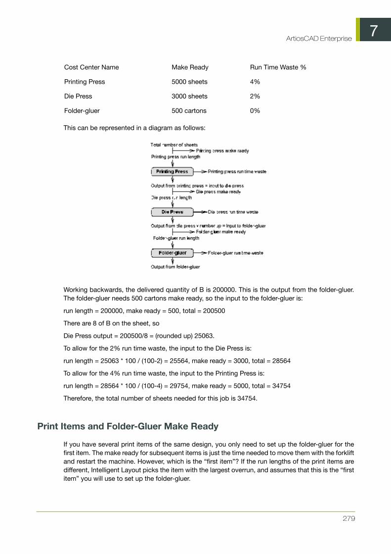
7ArtiosCAD Enterprise
279
Cost Center Name Make Ready Run Time Waste %
Printing Press 5000 sheets 4%
Die Press 3000 sheets 2%
Folder-gluer 500 cartons 0%
This can be represented in a diagram as follows:
Working backwards, the delivered quantity of B is 200000. This is the output from the folder-gluer.The folder-gluer needs 500 cartons make ready, so the input to the folder-gluer is:
run length = 200000, make ready = 500, total = 200500
There are 8 of B on the sheet, so
Die Press output = 200500/8 = (rounded up) 25063.
To allow for the 2% run time waste, the input to the Die Press is:
run length = 25063 * 100 / (100-2) = 25564, make ready = 3000, total = 28564
To allow for the 4% run time waste, the input to the Printing Press is:
run length = 28564 * 100 / (100-4) = 29754, make ready = 5000, total = 34754
Therefore, the total number of sheets needed for this job is 34754.
Print Items and Folder-Gluer Make Ready
If you have several print items of the same design, you only need to set up the folder-gluer for thefirst item. The make ready for subsequent items is just the time needed to move them with the forkliftand restart the machine. However, which is the “first item”? If the run lengths of the print items aredifferent, Intelligent Layout picks the item with the largest overrun, and assumes that this is the “firstitem” you will use to set up the folder-gluer.

7ArtiosCAD Enterprise
280
Configuring Outputs
Esko ArtiosCAD provides many ways to configure Outputs to get the results your company’sworkflow requires.
The tabs shown on an Output properties dialog box depend on the selection in the Output Typegroup. For example, in the picture above, there is no Reports tab, but if you set the Output Type toPlot, the samplemaking-related tabs disappear and the Report tab appears.
Note: Do not use a backward slash ( \ ) in any Output name.
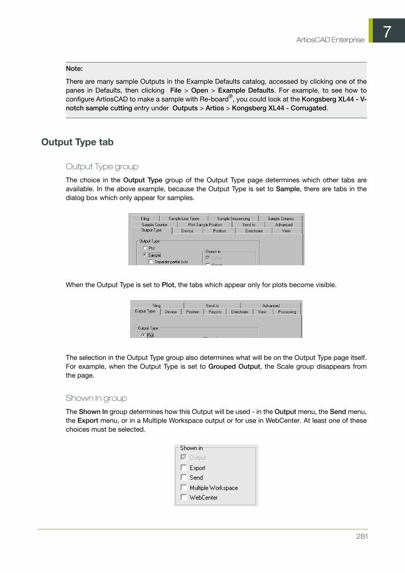
7ArtiosCAD Enterprise
281
Note:
There are many sample Outputs in the Example Defaults catalog, accessed by clicking one of thepanes in Defaults, then clicking File > Open > Example Defaults. For example, to see how toconfigure ArtiosCAD to make a sample with Re-board®, you could look at the Kongsberg XL44 - V-notch sample cutting entry under Outputs > Artios > Kongsberg XL44 - Corrugated.
Output Type tab
Output Type group
The choice in the Output Type group of the Output Type page determines which other tabs areavailable. In the above example, because the Output Type is set to Sample, there are tabs in thedialog box which only appear for samples.
When the Output Type is set to Plot, the tabs which appear only for plots become visible.
The selection in the Output Type group also determines what will be on the Output Type page itself.For example, when the Output Type is set to Grouped Output, the Scale group disappears fromthe page.
Shown In group
The Shown In group determines how this Output will be used - in the Output menu, the Send menu,the Export menu, or in a Multiple Workspace output or for use in WebCenter. At least one of thesechoices must be selected.
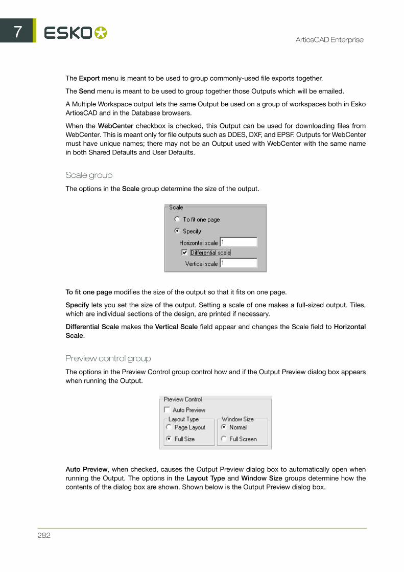
7ArtiosCAD Enterprise
282
The Export menu is meant to be used to group commonly-used file exports together.
The Send menu is meant to be used to group together those Outputs which will be emailed.
A Multiple Workspace output lets the same Output be used on a group of workspaces both in EskoArtiosCAD and in the Database browsers.
When the WebCenter checkbox is checked, this Output can be used for downloading files fromWebCenter. This is meant only for file outputs such as DDES, DXF, and EPSF. Outputs for WebCentermust have unique names; there may not be an Output used with WebCenter with the same namein both Shared Defaults and User Defaults.
Scale group
The options in the Scale group determine the size of the output.
To fit one page modifies the size of the output so that it fits on one page.
Specify lets you set the size of the output. Setting a scale of one makes a full-sized output. Tiles,which are individual sections of the design, are printed if necessary.
Differential Scale makes the Vertical Scale field appear and changes the Scale field to HorizontalScale.
Preview control group
The options in the Preview Control group control how and if the Output Preview dialog box appearswhen running the Output.
Auto Preview, when checked, causes the Output Preview dialog box to automatically open whenrunning the Output. The options in the Layout Type and Window Size groups determine how thecontents of the dialog box are shown. Shown below is the Output Preview dialog box.
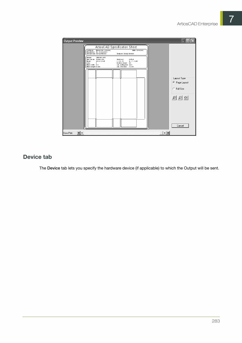
7ArtiosCAD Enterprise
283
Device tab
The Device tab lets you specify the hardware device (if applicable) to which the Output will be sent.

7ArtiosCAD Enterprise
284
When entering this tab for the first time, you may see a dialog box informing you that Esko ArtiosCADwas unable to find a certain printer. Ignore this and click OK to proceed.
In the Driver Type group, the Windows Driver option instructs Esko ArtiosCAD to send the outputinformation to the operating system mechanism of driving the device. The CAM Driver optioninstructs Esko ArtiosCAD to use its internal methods to drive the device. The selected option inthis group determines how the rest of the tab looks. Bitmap creates a picture file of the output.Workspace Layer creates a new layer in the workspace and draws the output data in that.
Note: When outputting to a layer, you must re-perform the Output after each rebuild to maintaincorrect information in the layer.
Out to file sends the output data to a disc file instead of physically out to a device through a port ornetwork connection. Some devices such as samplemakers make a network connection to the CADworkstation and pick up the file automatically.
Number of copies allows you to set the default number of copies made when performing this Output.
The value selected in the High graphics memory use drop-down list box determines how muchmemory Esko ArtiosCAD uses when outputting a bitmap image (typically a referenced PDF file whenthe PDF option has been purchased). This option is available only for Outputs of type Windows Driveror Bitmap.
A bitmap may have a maximum of 15 million pixels. The size of the bitmap is calculated dynamicallyduring the output; system performance may be affected if a large bitmap is required. You canset the maximum number of pixels for the Output to use to balance system speed and output
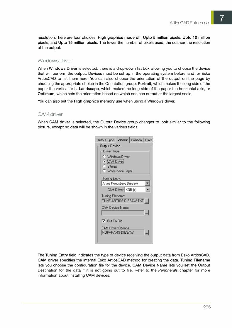
7ArtiosCAD Enterprise
285
resolution.There are four choices: High graphics mode off, Upto 5 million pixels, Upto 10 millionpixels, and Upto 15 million pixels. The fewer the number of pixels used, the coarser the resolutionof the output.
Windows driver
When Windows Driver is selected, there is a drop-down list box allowing you to choose the devicethat will perform the output. Devices must be set up in the operating system beforehand for EskoArtiosCAD to list them here. You can also choose the orientation of the output on the page bychoosing the appropriate choice in the Orientation group: Portrait, which makes the long side of thepaper the vertical axis, Landscape, which makes the long side of the paper the horizontal axis, orOptimum, which sets the orientation based on which one can output at the largest scale.
You can also set the High graphics memory use when using a Windows driver.
CAM driver
When CAM driver is selected, the Output Device group changes to look similar to the followingpicture, except no data will be shown in the various fields:
The Tuning Entry field indicates the type of device receiving the output data from Esko ArtiosCAD.CAM driver specifies the internal Esko ArtiosCAD method for creating the data. Tuning Filenamelets you choose the configuration file for the device. CAM Device Name lets you set the OutputDestination for the data if it is not going out to file. Refer to the Peripherals chapter for moreinformation about installing CAM devices.

7ArtiosCAD Enterprise
286
Bitmap outputs
The Bitmap driver type lets Esko ArtiosCAD output a bitmap picture of a workspace.
The option buttons in the Bitmap Format group set the type of bitmap created. JPEG output(Joint Photographic Experts Group) makes compressed pictures for efficient use in other programs,but some color information is lost. PNG output (Portable Network Graphic) is used for vectorgraphics (lines and arcs) shown on the World Wide Web. TIFF output (Tagged Image File Format) isuncompressed and is useful for other graphic programs such as Adobe Photoshop. Note, however,that TIFF files are usually quite large.
The Shrink size to remove white space checkbox, when checked, causes Esko ArtiosCAD to cropthe extra white space around the perimeter of the design upon Output.
The JPEG Quality field adjusts the quality and the file size of the resulting JPG file. A value of 0makes the smallest file with the worst quality, while a value of 100 makes the largest file with the bestquality. Esko ArtiosCAD defaults to 70. Set the value in this field between 80 and 90 if you will bemaking Animations in 3D. This field is available only when the Bitmap Format is set to JPEG.
High graphics memory use determines how much memory Esko ArtiosCAD uses to render PDFgraphics being processed by the Output.
Getting bitmap outputs just right can take some experimentation.
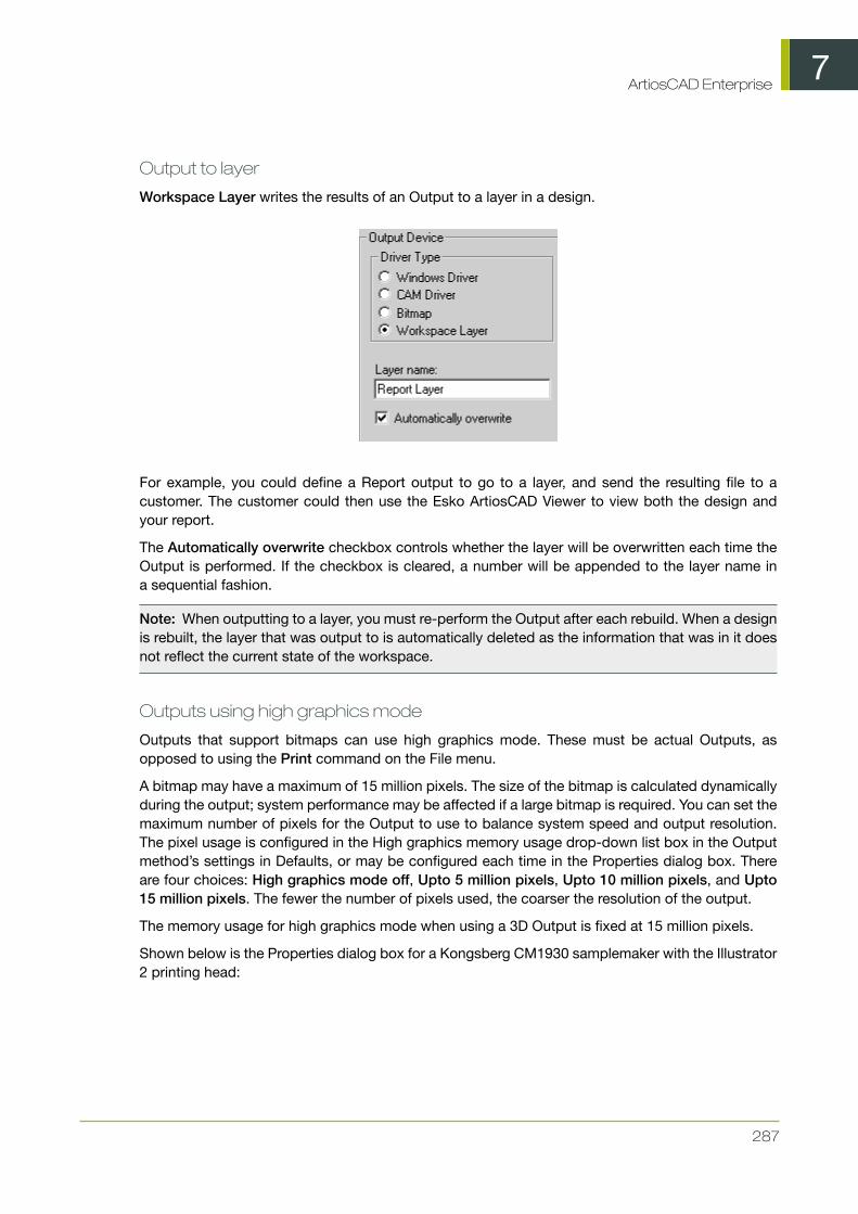
7ArtiosCAD Enterprise
287
Output to layer
Workspace Layer writes the results of an Output to a layer in a design.
For example, you could define a Report output to go to a layer, and send the resulting file to acustomer. The customer could then use the Esko ArtiosCAD Viewer to view both the design andyour report.
The Automatically overwrite checkbox controls whether the layer will be overwritten each time theOutput is performed. If the checkbox is cleared, a number will be appended to the layer name ina sequential fashion.
Note: When outputting to a layer, you must re-perform the Output after each rebuild. When a designis rebuilt, the layer that was output to is automatically deleted as the information that was in it doesnot reflect the current state of the workspace.
Outputs using high graphics mode
Outputs that support bitmaps can use high graphics mode. These must be actual Outputs, asopposed to using the Print command on the File menu.
A bitmap may have a maximum of 15 million pixels. The size of the bitmap is calculated dynamicallyduring the output; system performance may be affected if a large bitmap is required. You can set themaximum number of pixels for the Output to use to balance system speed and output resolution.The pixel usage is configured in the High graphics memory usage drop-down list box in the Outputmethod’s settings in Defaults, or may be configured each time in the Properties dialog box. Thereare four choices: High graphics mode off, Upto 5 million pixels, Upto 10 million pixels, and Upto15 million pixels. The fewer the number of pixels used, the coarser the resolution of the output.
The memory usage for high graphics mode when using a 3D Output is fixed at 15 million pixels.
Shown below is the Properties dialog box for a Kongsberg CM1930 samplemaker with the Illustrator2 printing head:

7ArtiosCAD Enterprise
288
Shown below is the Plot to Printer dialog box.
Position tab
The settings on the Position tab indicate the physical placement of the output on the output medium.

7ArtiosCAD Enterprise
289
Device Size and Margin groups
The fields in the Device Size group let you set the size of the device (if you are using a CAM driver;otherwise, the size fields are unavailable) and the starting position as measured from the bottom leftcorner of the medium.
The settings in the Margin group set the distance between the edge of the medium and the physicalarea that can be printed by the device. When you set the device size to 0 (for unlimited size), youcan still set the margins.
Orientation and Position groups
The commands in the Orientation group let you specify the relative position of the output on thedevice.
The options in the Position group control the point to which the output is snapped on the device andthe side of the design which is output. The nine buttons snap the design to their respective locationon the page - top left corner, top center, top right corner, right center, bottom right corner, bottomcenter, bottom left corner, left center, and center.
The Side Up list box lets you choose which side of the design is output: the Inside, Outside, DieKnife side, Die back side, or the default side, which is the current side of the design.
Reports tab
The Reports tab lets you specify a report to output using the data in the design. Check the UseReport checkbox and choose the report to use.
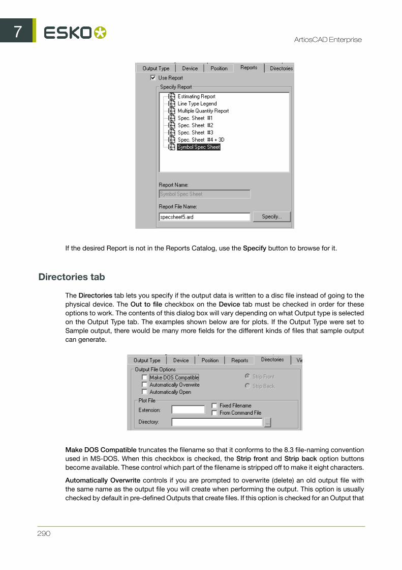
7ArtiosCAD Enterprise
290
If the desired Report is not in the Reports Catalog, use the Specify button to browse for it.
Directories tab
The Directories tab lets you specify if the output data is written to a disc file instead of going to thephysical device. The Out to file checkbox on the Device tab must be checked in order for theseoptions to work. The contents of this dialog box will vary depending on what Output type is selectedon the Output Type tab. The examples shown below are for plots. If the Output Type were set toSample output, there would be many more fields for the different kinds of files that sample outputcan generate.
Make DOS Compatible truncates the filename so that it conforms to the 8.3 file-naming conventionused in MS-DOS. When this checkbox is checked, the Strip front and Strip back option buttonsbecome available. These control which part of the filename is stripped off to make it eight characters.
Automatically Overwrite controls if you are prompted to overwrite (delete) an old output file withthe same name as the output file you will create when performing the output. This option is usuallychecked by default in pre-defined Outputs that create files. If this option is checked for an Output that
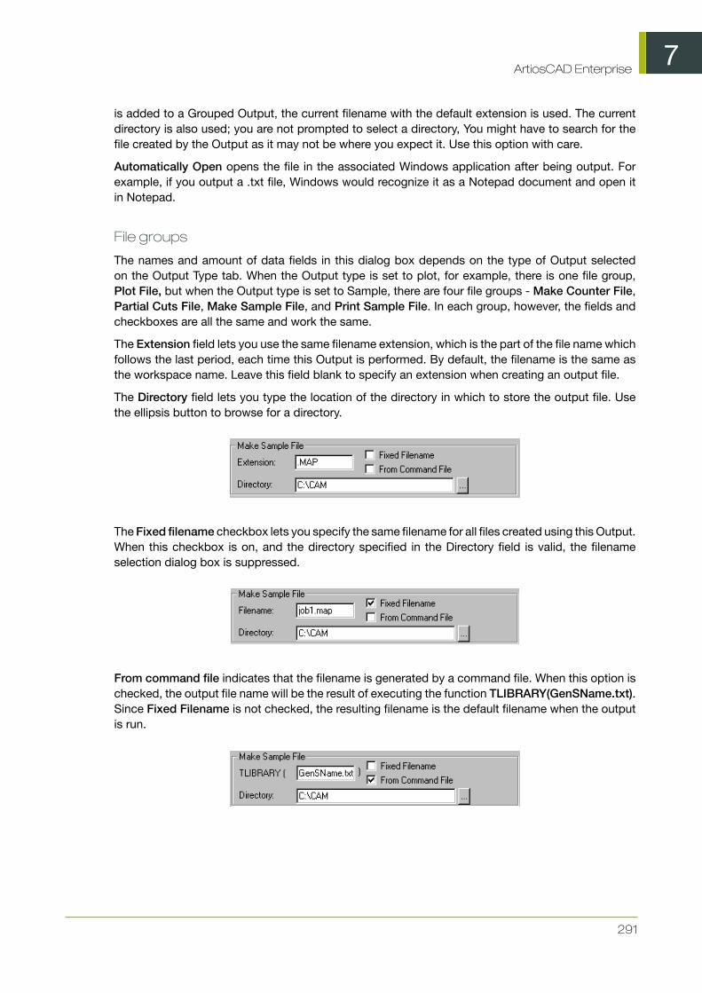
7ArtiosCAD Enterprise
291
is added to a Grouped Output, the current filename with the default extension is used. The currentdirectory is also used; you are not prompted to select a directory, You might have to search for thefile created by the Output as it may not be where you expect it. Use this option with care.
Automatically Open opens the file in the associated Windows application after being output. Forexample, if you output a .txt file, Windows would recognize it as a Notepad document and open itin Notepad.
File groups
The names and amount of data fields in this dialog box depends on the type of Output selectedon the Output Type tab. When the Output type is set to plot, for example, there is one file group,Plot File, but when the Output type is set to Sample, there are four file groups - Make Counter File,Partial Cuts File, Make Sample File, and Print Sample File. In each group, however, the fields andcheckboxes are all the same and work the same.
The Extension field lets you use the same filename extension, which is the part of the file name whichfollows the last period, each time this Output is performed. By default, the filename is the same asthe workspace name. Leave this field blank to specify an extension when creating an output file.
The Directory field lets you type the location of the directory in which to store the output file. Usethe ellipsis button to browse for a directory.
The Fixed filename checkbox lets you specify the same filename for all files created using this Output.When this checkbox is on, and the directory specified in the Directory field is valid, the filenameselection dialog box is suppressed.
From command file indicates that the filename is generated by a command file. When this option ischecked, the output file name will be the result of executing the function TLIBRARY(GenSName.txt).Since Fixed Filename is not checked, the resulting filename is the default filename when the outputis run.

7ArtiosCAD Enterprise
292
View tab
The options on the View tab of the Output dialog box control how the layers and line types are output.
Style Selection group
Specify Plotting Style overrides the plotting style at time of output with the plotting style specifiedin the Available Plotting Styles drop-down list box. The list box is available only when this option ischecked. Checking Rule labels turns on rule labels for this Output.

7ArtiosCAD Enterprise
293
Dimension Position group
Auto-adjust overlapping text prevents rogue text items from being printed on top of each other. Youcan specify the range of text sizes to consider when Esko ArtiosCAD looks for overlapping text byentering point values in the Minimum text size and Maximum text size fields.
The Remove extension lines checkbox controls whether extension lines are removed if text has tobe moved to make it not overlap.
Override Dimension Format group
The options in the Override Dimension Format group allow you to override the workspace settingsfor the dimension format with those that you choose in this group. Set them as desired.
View Selection group
The options in the View Selection group control which layers are output when running the output.
Current zoomed in view Outputs the objects in the current zoomed in area. In this case the Layerset selection is set to Current View and the Available Layers list is unavailable.
Current selection uses the currently selected items as the Output. All non-selected items are ignored.If no items are selected, the Output defaults to the Current View Layer set selection.
The Use selection for report calculations checkbox is only available with Current selection and isonly applicable if the Output uses a Report. This option forces the calculated text commands in theReport to be evaluated against a temporary document which contains a copy of the selected item.
Choose the layer to output from the Layer Set Selection drop-down list box.

7ArtiosCAD Enterprise
294
Choosing a layer set from the drop-down list box toggles different layers in the Available Layersgroup. Select or deselect layers as desired. To choose specific layers without starting from apreconfigured layer set, select the User Defined layer set, and then select layers as desired.
Note: Do not select both the Designs layer and Rule Path layer for any Output.
The options in the Rotary Diemaking View Level group control how the size of the Output ismanipulated when the Layer Set Selection is set to Dieboard. Design Level, Wood Level, andCylinder Level apply the appropriate shrink or stretch factors to the output data so that the outputis sized correctly.
Processing tab
The commands on the Processing tab control how the data is manipulated between when you clickOutput and when the data arrives at the output device or disc file.

7ArtiosCAD Enterprise
295
Note: The options on the Processing tab depend on the type of output chosen on the Output Typetab. Different outputs have different options.
The Browse button at the end of the CAM Tooling Setup field lets you choose the CAM ToolingSetup to use in this Output. The CAM Tooling Setup maps which line types are mapped to whichphysical tools on the output device. Click it to choose an entry from the Select Cam Tooling dialogbox.
Optimization options group
Depending on the Output Type chosen, items in this group may be unavailable.
No optimization makes no changes to the output data.
Plotter Pen Optimization examines each 100 lines of output code, groups together lines made withthe same pen, outputs them, and then examines the next 100 lines.

7ArtiosCAD Enterprise
296
Enable subroutined output means support subroutines in the NC (numeric control) output, whichonly works with the PUNCH command and certain SAVE commands. Turning this checkbox offcombines all elements of the design or manufacturing file into one set of data on output.
Enable subroutined output also works and should normally be checked for CFF2-Save and DDES-Save and Elcede exports. For a driver that supports this option, checking this checkbox causes eachdifferent design to be output as a subroutine, with a call to that subroutine for each instance of thedesign on the sheet. This saves memory in the controller for an NC output, and differentiates eachdesign from the layout in DDES and CFF2 output. When this checkbox is clear, the entire layout isoutput flat, as if it were one big design. This option must be checked for the Layout Sequencinggroup to be available.
Line processing options group
The option buttons in this group determine how lines are physically output.
No processing ignores bridges and outputs each special rule as a single line.
Design representation means that special rules are output as “actual” lines; for example, a waverule would be output as a series of arcs.
Partially-cut bridges instructs the output device to cut into the material at a partial depth to makeroom for bridges in the rule.
Leave gaps for bridges splits the line output data into pieces and leaves gaps in the output data forbridges, meaning that no slot or line is created in the output material where the bridges occur.
Software line styles processes all line styles before they are sent to the driver. For example, whenthis option is selected, a perf would be broken up into a series of short cut lines and gaps instead ofone line marked perf that the driver would then process. This option is available only for Plot outputs.
Layout Sequencing group
The options in this group are shown only when the output type is set to Plot, CAM, Sample, orCounter on the Output Type tab. Enable subroutined output in the Optimization options group mustbe turned on for this group to be available in Plot and CAM outputs.
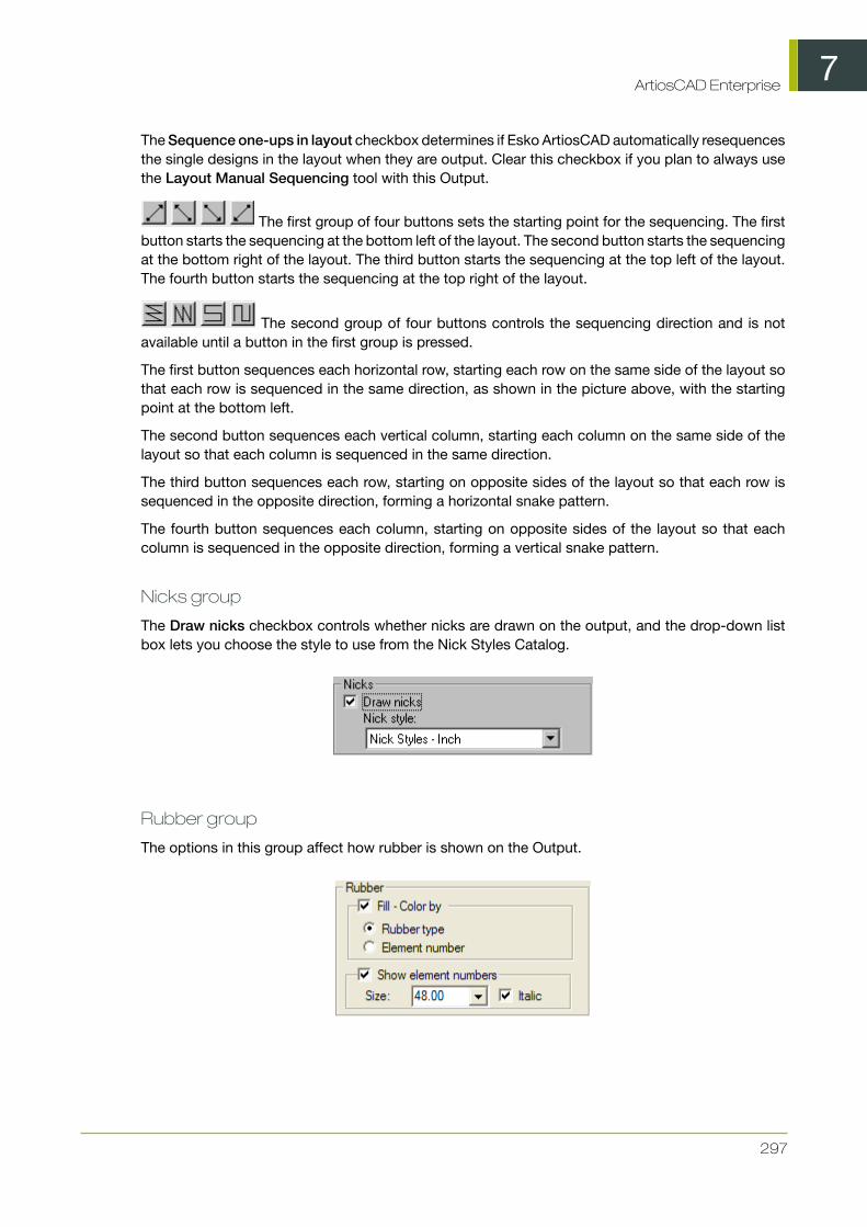
7ArtiosCAD Enterprise
297
The Sequence one-ups in layout checkbox determines if Esko ArtiosCAD automatically resequencesthe single designs in the layout when they are output. Clear this checkbox if you plan to always usethe Layout Manual Sequencing tool with this Output.
The first group of four buttons sets the starting point for the sequencing. The firstbutton starts the sequencing at the bottom left of the layout. The second button starts the sequencingat the bottom right of the layout. The third button starts the sequencing at the top left of the layout.The fourth button starts the sequencing at the top right of the layout.
The second group of four buttons controls the sequencing direction and is notavailable until a button in the first group is pressed.
The first button sequences each horizontal row, starting each row on the same side of the layout sothat each row is sequenced in the same direction, as shown in the picture above, with the startingpoint at the bottom left.
The second button sequences each vertical column, starting each column on the same side of thelayout so that each column is sequenced in the same direction.
The third button sequences each row, starting on opposite sides of the layout so that each row issequenced in the opposite direction, forming a horizontal snake pattern.
The fourth button sequences each column, starting on opposite sides of the layout so that eachcolumn is sequenced in the opposite direction, forming a vertical snake pattern.
Nicks group
The Draw nicks checkbox controls whether nicks are drawn on the output, and the drop-down listbox lets you choose the style to use from the Nick Styles Catalog.
Rubber group
The options in this group affect how rubber is shown on the Output.

7ArtiosCAD Enterprise
298
If Fill - Color by is selected, the rubber is drawn filled with color; choose to color the rubber byRubber type or Element number. Esko ArtiosCAD cycles through about 10 colors when drawing byelement number. If Fill - Color by is not selected, the rubber is drawn as outlines.
To draw the element number inside each piece of rubber, select Show element numbers, and thenset the Size: field (in points) and Italic checkbox as desired.
Dieboard group
The options in the this group control how the dieboard is created for a relevant Output type.
Ignore die splits (full dieboard) makes a full dieboard regardless of any splits.
Undercut at die splits by instructs the output device to cut back each line leading up to a die splitfrom the split by the amount specified. Bridge positions are correctly maintained.
Undercut at crease ends by instructs the output device to put a bridge of the size specified at eachend of all creases. If a crease line is bridged, any cutback may not exceed the size of the bridgewidth. If this option is chosen, set the minimum size of the line that will be undercut in the Minimumcrease length: field.
Text options group
Plotter font tells the output device to use its built-in font for rendering the text. Use this option forpen plotters or for a driver that supports simple text entities, but not fonts, such as CFF2, DDES,Elcede DieCAD, and DXF.
Line text converts the text to geometry, which is then affected by transformations on output. Linetext is suitable for etching text on a die. This is particularly useful for Asian languages, because theName tool in Manufacturing only supports ASCII characters. To use Line text on a die or strippingtool, add a text item in a suitable font to the die or stripping board layer, with no color, and use anoutput configured with Line text. A suitable font for line text should be simple, have parallel edges,and not be too thick.
Normal text leaves the text alone. Normal text will always be output so that it is readable, regardlessof dieboard orientation. This is suitable for output formats that support fonts, such as all Windowsdrivers, EPSF, and bitmap outputs

7ArtiosCAD Enterprise
299
Text is always output right side up, for all three of the above options. The only way to output textbackwards is to convert the text to lines in the design using the Outline Text or Line Text tools.
Diesaw tab
Kongsberg DieSaw group
This tab appears only when the output is to a Kongsberg DieSaw.
Full board depth is the thickness of the dieboard.
Generate saw leader holes controls whether Esko ArtiosCAD creates leader holes. Leader holesare drilled holes in the dieboard which allow the saw to position itself to start cutting in the properposition. They are made before any saw cuts.
No leader holes in corners, when checked, prevents Esko ArtiosCAD from automatically creatingleader holes in corners. Leader holes are instead put on bridges of the lines that meet to form a corner.
Adjust leader holes on bridges allows Esko ArtiosCAD to move the leader holes further apart fromeach other if they occur at either end of a bridge. When this happens, the amount of material leftbetween the two holes is not strong enough and could break; therefore, the centers of the leaderholes are offset from the ends of the lines to prevent bridge breakage. The picture below illustratesthis process.
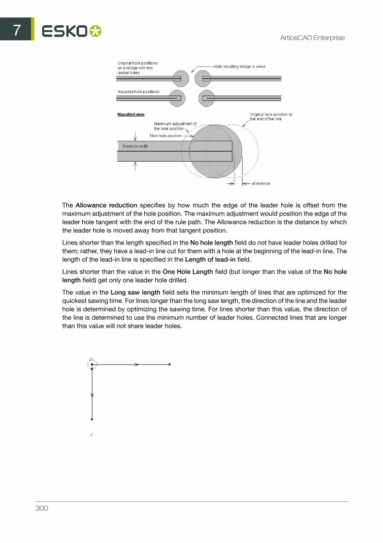
7ArtiosCAD Enterprise
300
The Allowance reduction specifies by how much the edge of the leader hole is offset from themaximum adjustment of the hole position. The maximum adjustment would position the edge of theleader hole tangent with the end of the rule path. The Allowance reduction is the distance by whichthe leader hole is moved away from that tangent position.
Lines shorter than the length specified in the No hole length field do not have leader holes drilled forthem; rather, they have a lead-in line cut for them with a hole at the beginning of the lead-in line. Thelength of the lead-in line is specified in the Length of lead-in field.
Lines shorter than the value in the One Hole Length field (but longer than the value of the No holelength field) get only one leader hole drilled.
The value in the Long saw length field sets the minimum length of lines that are optimized for thequickest sawing time. For lines longer than the long saw length, the direction of the line and the leaderhole is determined by optimizing the sawing time. For lines shorter than this value, the direction ofthe line is determined to use the minimum number of leader holes. Connected lines that are longerthan this value will not share leader holes.

7ArtiosCAD Enterprise
301
Tiling tab
The settings on the Tiling tab control what happens when the scale of the output is too big to fit onone sheet of output medium.
Skip empty tiles tells Esko ArtiosCAD to not output blank tiles. If you will be assembling all the tilestogether into one big sheet, you may want to leave this option unchecked so as not to confuse theassembler.
Confirmation required for each tile, when outputting directly to a device tells Esko ArtiosCAD toprompt you to click OK before outputting each tile. This is handy for when you have to reload mediaon the output device in between tiles.

7ArtiosCAD Enterprise
302
Tile registration group
The options in this group control how the tiles are marked for assembly.
Registration cross size is the overall height and width of the cross mark. Setting this option to zeroturns off the drawing of registration crosses in the output. Also, registration crosses are only drawnin the corner of tiles which align with other tiles; a registration mark will never be drawn in the bottomleft corner of the first tile.
Tile overlap is the amount of overlap from one tile to the next. This value will be used for both thehorizontal and vertical overlap. A value of zero means no overlap, and when used with registrationcrosses, turns the cross marks into corner marks.
Samplemaking registration hole diameter is only available for Sample outputs and is the diameterof the hole cut into the sample material to aid in registering oversized samples. The diameter valuemust be between zero and the size of the registration crosses. The hole is centered on the registrationmark.
Using sample counter and Just draw registration marks are also only available for Sample outputs.These options indicate if a counter is being used when this Output is run. If Just draw registrationmarks is selected, then the Make Counter button on the main sample output dialog (what you seenwhen you perform the Output) is replaced with a Draw Registration button. This button is unavailableif tiling is not required. Selecting this option will generate output files (using the Make Counter filedesignations) with just the tile registration marks drawn using a sample pen.
Output filename generation group
The options in the Output Filename Generation group automatically constructs a unique file namefor each tile when the output is set to go out to file. When both conditions are met (Out to file anda scale larger than can fit on the output device), the options in this group change the name out ofthe output file to indicate the separate tiles.

7ArtiosCAD Enterprise
303
Sample line types tab
You configure the line types and tools used in samplemaking on the Sample line types tab.
To configure how the line type is handled when performing this Output, select the line type in theLine type: group and choose the tool in the Samplemaking tool: group. There may be settings forthe tool that appear in the bottom right corner; if there are, set them as desired.
As with other tabs, the information displayed on this tab is conditional; that is, the informationrequested on the right side of the tab depends on the selected item on the left side of the tab. Whatyou see will not necessarily look exactly like the picture above.
To make nicks in the sample whose size based on the caliper of the board, enter a multiplier in thefield next to + CAL *.

7ArtiosCAD Enterprise
304
To cut stripping rules on the sample, check the Cut stripping rules checkbox. Stripping rules are cutoutward from the design to avoid overcuts.
The Size only samplemaking tool is used to calculate the output size. Use it only when outputtingto a layer.
When using Re-board®, samplemakers cannot cut small holes in the material and use a drill toolinstead. Therefore, enter an appropriate value in Drill holes smaller than diameter for holes that aredrilled and not cut. If you will be using drill holes, you should update the Sample drill hole line type onthe Sample tab of your plotting style definition so that it uses a thicker solid line instead of the default.
Text options group
Plotter font tells the output device to use its built-in font for rendering the text. Use this option forpen plotters or for a driver that supports simple text entities, but not fonts, such as CFF2, DDES,Elcede DieCAD, and DXF.
Line text converts the text to geometry, which is then affected by transformations on output. Linetext is suitable for etching text on a die. This is particularly useful for Asian languages, because theName tool in Manufacturing only supports ASCII characters. To use Line text on a die or strippingtool, add a text item in a suitable font to the die or stripping board layer, with no color, and use anoutput configured with Line text. A suitable font for line text should be simple, have parallel edges,and not be too thick.
Normal text leaves the text alone. Normal text will always be output so that it is readable, regardlessof dieboard orientation. This is suitable for output formats that support fonts, such as all Windowsdrivers, EPSF, and bitmap outputs
Text is always output right side up, for all three of the above options. The only way to output textbackwards is to convert the text to lines in the design using the Outline Text or Line Text tools.
Make nicks in sample group
The Make nicks in sample checkbox controls if nicks are made when cutting a sample. Check thebox to have the samplecutter make the nicks as defined in the design being output, or clear it to
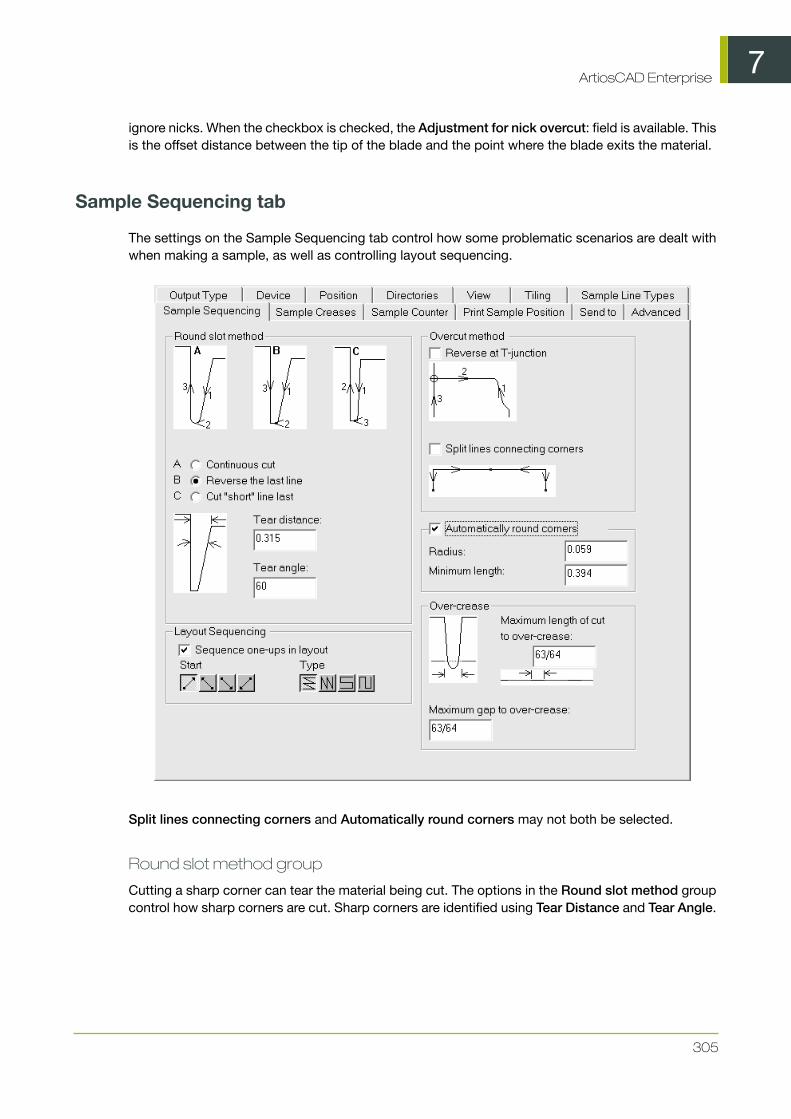
7ArtiosCAD Enterprise
305
ignore nicks. When the checkbox is checked, the Adjustment for nick overcut: field is available. Thisis the offset distance between the tip of the blade and the point where the blade exits the material.
Sample Sequencing tab
The settings on the Sample Sequencing tab control how some problematic scenarios are dealt withwhen making a sample, as well as controlling layout sequencing.
Split lines connecting corners and Automatically round corners may not both be selected.
Round slot method group
Cutting a sharp corner can tear the material being cut. The options in the Round slot method groupcontrol how sharp corners are cut. Sharp corners are identified using Tear Distance and Tear Angle.
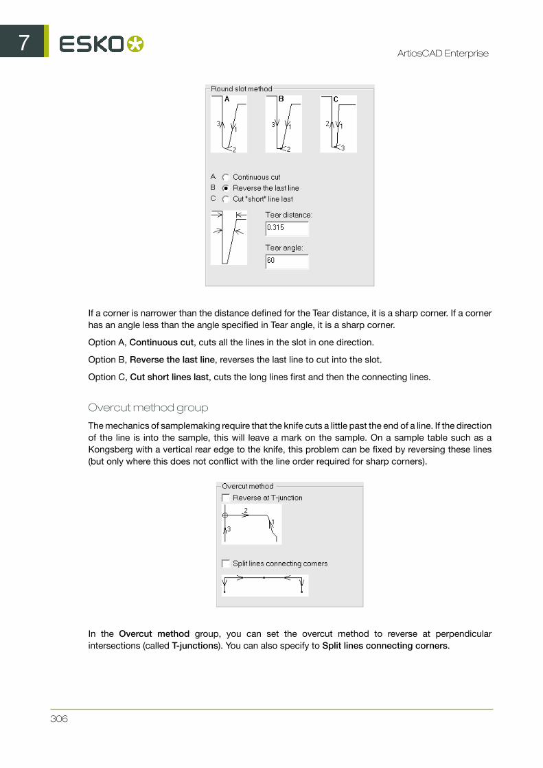
7ArtiosCAD Enterprise
306
If a corner is narrower than the distance defined for the Tear distance, it is a sharp corner. If a cornerhas an angle less than the angle specified in Tear angle, it is a sharp corner.
Option A, Continuous cut, cuts all the lines in the slot in one direction.
Option B, Reverse the last line, reverses the last line to cut into the slot.
Option C, Cut short lines last, cuts the long lines first and then the connecting lines.
Overcut method group
The mechanics of samplemaking require that the knife cuts a little past the end of a line. If the directionof the line is into the sample, this will leave a mark on the sample. On a sample table such as aKongsberg with a vertical rear edge to the knife, this problem can be fixed by reversing these lines(but only where this does not conflict with the line order required for sharp corners).
In the Overcut method group, you can set the overcut method to reverse at perpendicularintersections (called T-junctions). You can also specify to Split lines connecting corners.
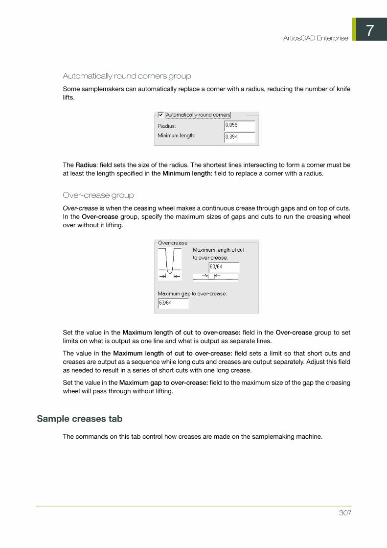
7ArtiosCAD Enterprise
307
Automatically round corners group
Some samplemakers can automatically replace a corner with a radius, reducing the number of knifelifts.
The Radius: field sets the size of the radius. The shortest lines intersecting to form a corner must beat least the length specified in the Minimum length: field to replace a corner with a radius.
Over-crease group
Over-crease is when the ceasing wheel makes a continuous crease through gaps and on top of cuts.In the Over-crease group, specify the maximum sizes of gaps and cuts to run the creasing wheelover without it lifting.
Set the value in the Maximum length of cut to over-crease: field in the Over-crease group to setlimits on what is output as one line and what is output as separate lines.
The value in the Maximum length of cut to over-crease: field sets a limit so that short cuts andcreases are output as a sequence while long cuts and creases are output separately. Adjust this fieldas needed to result in a series of short cuts with one long crease.
Set the value in the Maximum gap to over-crease: field to the maximum size of the gap the creasingwheel will pass through without lifting.
Sample creases tab
The commands on this tab control how creases are made on the samplemaking machine.
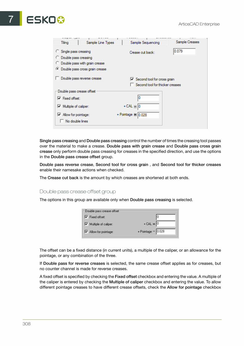
7ArtiosCAD Enterprise
308
Single pass creasing and Double pass creasing control the number of times the creasing tool passesover the material to make a crease. Double pass with grain crease and Double pass cross graincrease only perform double pass creasing for creases in the specified direction, and use the optionsin the Double pass crease offset group.
Double pass reverse crease, Second tool for cross grain , and Second tool for thicker creasesenable their namesake actions when checked.
The Crease cut back is the amount by which creases are shortened at both ends.
Double pass crease offset group
The options in this group are available only when Double pass creasing is selected.
The offset can be a fixed distance (in current units), a multiple of the caliper, or an allowance for thepointage, or any combination of the three.
If Double pass for reverse creases is selected, the same crease offset applies as for creases, butno counter channel is made for reverse creases.
A fixed offset is specified by checking the Fixed offset checkbox and entering the value. A multiple ofthe caliper is entered by checking the Multiple of caliper checkbox and entering the value. To allowdifferent pointage creases to have different crease offsets, check the Allow for pointage checkbox

7ArtiosCAD Enterprise
309
and enter the width of the scoring wheel. This defaults to 0.028 inches = 2 points; this adds (pointage- value) to the crease offset.
Sample Counter tab
The options on this tab control how sample counters are made. For each type of crease in theParameter for: group, you can set the type of crease channel as well as the widths, counter cutback, and the channel angle. Routed counters invoke conditional text by deleting the field for thechannel angle and inserting fields for the routing tool widths. The grain angle tolerance is the samefor all crease types.
Print Sample Position tab
The Print Sample Position tab lets you specify how to print sample graphics on your sample printer.

7ArtiosCAD Enterprise
310
This tab contains the exact same controls as the Position tab.
Send to tab
The commands on the Send to tab let you send the results of the Output via email. The design fileitself is not sent when an Output with this option enabled is run. You must have a MAPI-compliantmail program such as Microsoft Outlook installed on your computer for this to work. If you do nothave a MAPI-compliant email program installed, you will receive error messages when you attemptany email-related functions.
The Use email checkbox turns on this feature.
The To and Cc buttons let you choose recipients from your mail program’s address book.
Prompt for message opens the message in your email program. If this option is not checked, themessage is sent with no user intervention.
Attach to email sends the output as an attachment, while Put contents in email inserts the text ofthe output into the message body.
Delete output disk file deletes the file created by the Output after it is added to the email. To preservethe file, clear this checkbox.
Advanced tab
The commands on the Advanced tab are meant to be used by people with very specific needs.
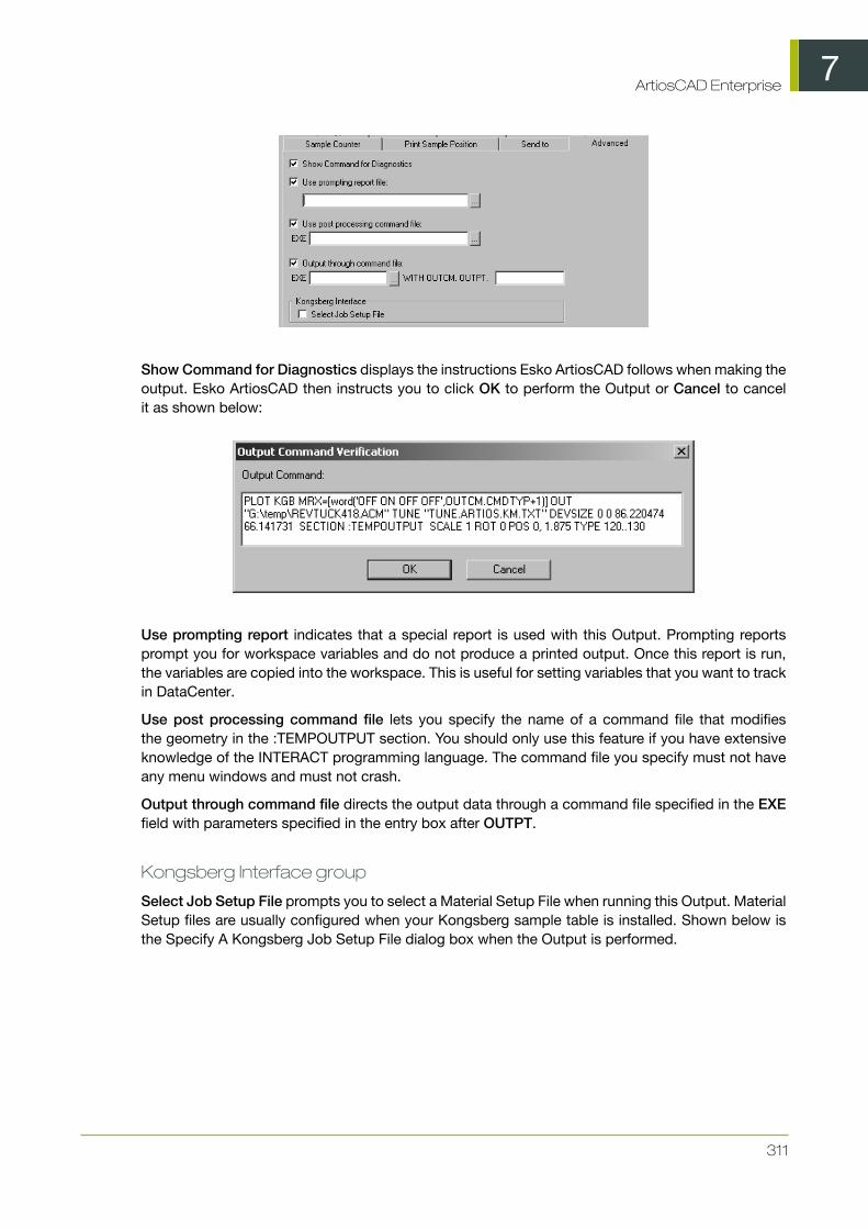
7ArtiosCAD Enterprise
311
Show Command for Diagnostics displays the instructions Esko ArtiosCAD follows when making theoutput. Esko ArtiosCAD then instructs you to click OK to perform the Output or Cancel to cancelit as shown below:
Use prompting report indicates that a special report is used with this Output. Prompting reportsprompt you for workspace variables and do not produce a printed output. Once this report is run,the variables are copied into the workspace. This is useful for setting variables that you want to trackin DataCenter.
Use post processing command file lets you specify the name of a command file that modifiesthe geometry in the :TEMPOUTPUT section. You should only use this feature if you have extensiveknowledge of the INTERACT programming language. The command file you specify must not haveany menu windows and must not crash.
Output through command file directs the output data through a command file specified in the EXEfield with parameters specified in the entry box after OUTPT.
Kongsberg Interface group
Select Job Setup File prompts you to select a Material Setup File when running this Output. MaterialSetup files are usually configured when your Kongsberg sample table is installed. Shown below isthe Specify A Kongsberg Job Setup File dialog box when the Output is performed.

7ArtiosCAD Enterprise
312
Record Variable Definition
These records and variables are created in the Output that is acted upon by the command file youspecify in the Output through command file checkbox. Use these records to get information fromthe design to the command file.
Record Variable Sub-variable Definition
&OUTCM.
CMD$ the actual command that would be issued
DEBUG 1 if “Show Command for Diagnostics” isON, else 0
CMDTY$ the command type “PLOT”, “PUNCH” or“SAVE”
CMDTYP command type - if (OTPTYP = 0 or 2) = 0,else (OTPTYP = 1) = 0 for Make Counter, 1= Make Sample, 2 = Partial Cuts, 3 = PrintSample
DRV$ the driver name e.g. “PRTMAN”, “HP”
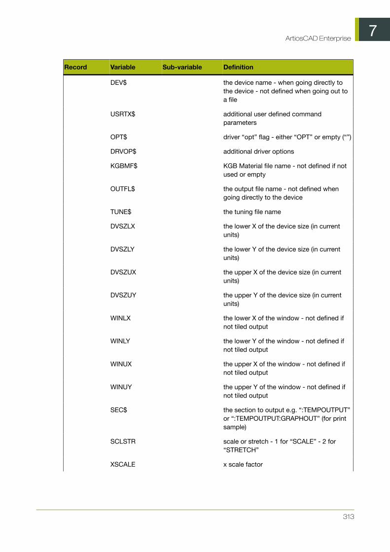
7ArtiosCAD Enterprise
313
Record Variable Sub-variable Definition
DEV$ the device name - when going directly tothe device - not defined when going out toa file
USRTX$ additional user defined commandparameters
OPT$ driver “opt” flag - either “OPT” or empty (“”)
DRVOP$ additional driver options
KGBMF$ KGB Material file name - not defined if notused or empty
OUTFL$ the output file name - not defined whengoing directly to the device
TUNE$ the tuning file name
DVSZLX the lower X of the device size (in currentunits)
DVSZLY the lower Y of the device size (in currentunits)
DVSZUX the upper X of the device size (in currentunits)
DVSZUY the upper Y of the device size (in currentunits)
WINLX the lower X of the window - not defined ifnot tiled output
WINLY the lower Y of the window - not defined ifnot tiled output
WINUX the upper X of the window - not defined ifnot tiled output
WINUY the upper Y of the window - not defined ifnot tiled output
SEC$ the section to output e.g. “:TEMPOUTPUT”or “:TEMPOUTPUT:GRAPHOUT” (for printsample)
SCLSTR scale or stretch - 1 for “SCALE” - 2 for“STRETCH”
XSCALE x scale factor

7ArtiosCAD Enterprise
314
Record Variable Sub-variable Definition
YSCALE y scale factor (set to XSCALE whenSCLSTR = 1)
NEGX$ either “NEG X” or EMPTY (“”)
ROT rotation in degrees
POSX X position in current units
POSY Y position in current units
LTYPS$ the parameters to the TYPE keyword e.g.“TYPE #SCUT, #SCREASE..#SRXCREASENOGRAPH” or empty(“”)
STY$ the plotting style to use e.g. “STY artios1”or empty (“”)
TILEX for tiling - the row of this tile
TILEY for tiling - the column of this tile
&OUTPT. output properties
OTPTYP the output type 0 = PLOT, 1 = SAMPLE or 2= MFG
OTPNM$ the name of the output
USESCL 1 to use the scale given - else automaticallycalculate it
SCALE the scale factor given
USESTR 1 to use “STRETCH” instead of “SCALE”
YSCALE the y-scale factor given
USEFRM 1 - this output uses a form
FRMNM$ the name of the form
DRV. the driver/positioning data
DRVTYP 0 - Windows driver, 1 = CAM driver
PRTR$ name of the windows printer
TOFIL 1- when output is set to file
ORIENT 0=Portrait, 1=Landscape, 2=Optimum -onlyused for a windows driver always portraitfor CAM
TNDES$ the description as read from TUNEFILES

7ArtiosCAD Enterprise
315
Record Variable Sub-variable Definition
TNFIL$ tuning file name
DRVNM$ the driver name as read from TUNEFILESe.g. HP
DVNAM$ name of CAM device for LP devices; e.g.HP1, DDES etc.
DROPT$ the CAM driver options
DEVSZX CAM device size in X in current units
DEVSZY CAM device size in Y in current units
MGTOP CAM top margin in current units
MGBOT CAM bottom margin in current units
MGLEFT CAM left margin in current units
MGRGHT CAM right margin in current units
OFFSTX X offset from the justification position incurrent units
OFFSTY Y offset from the justification position incurrent units
STARTX X origin shift
STARTY Y origin shift
ROT Rotation flag: 0=rotate 0, 1=rotate 90,2=rotate 180, 3=rotate -90
MIRROR Mirror flag: 0=no mirror, 1=mirror horiz.,2=mirror vert
JUST Justification flag: 0=top left, 1=top center,1=top right, 3=center left, 4=center,5=center right, 6=bottom left, 7=bottomcenter, 8=bottom right
SIDE Side flag: 0 = PRINTEDSIDE, 1 =UNPRINTEDSIDE, 2 = default side
TILED 0 if we don't need tiling
TILESX number of tile rows
TILESY number of tile columns
TLOVLP tile overlap

7ArtiosCAD Enterprise
316
Record Variable Sub-variable Definition
PSDRV. the optional print sample driver/positioningdata
DRVTYP 0 - Windows driver, 1 = CAM driver, 2 noprinter
PRTR$ name of the windows printer
TOFIL 1- when output is set to file
ORIENT 0=Portrait, 1=Landscape, 2=Optimum (2is only used for a Windows driver) alwaysportrait for CAM
TNDES$ the description as read from TUNEFILES
TNFIL$ tuning file name
DRVNM$ the driver name as read from TUNEFILESe.g. HP
DVNAM$ name of CAM device for LP devices; e.g.HP1, DDES etc.
DROPT$ the CAM driver options
DEVSZX CAM device size in X in current units
DEVSZY CAM device size in Y in current units
MGTOP CAM top margin in current units
MGBOT
MGLEFT CAM left margin in current units
MGRGHT CAM right margin in current units
OFFSTX X offset from the justification position incurrent units
OFFSTY Y offset from the justification position incurrent units
STARTX X origin shift
STARTY Y origin shift
ROT Rotation flag: 0=rotate 0, 1=rotate 90,2=rotate 180, 3=rotate -90
MIRROR Mirror flag: 0=no mirror, 1=mirror horiz.,2=mirror vert

7ArtiosCAD Enterprise
317
Record Variable Sub-variable Definition
JUST Justification flag: 0=top left, 1=top center,1=top right, 3=center left, 4=center,5=center right, 6=bottom left, 7=bottomcenter, 8=bottom right
SIDE Side flag: 0 = PRINTEDSIDE, 1 =UNPRINTEDSIDE, 2 = default side
Information Filter tab
The commands on the Information Filter tab let you select the Esko ArtiosCAD data included in theOutput. The Output type must be set to Information Filter to make this tab appear.
Note: The settings on this tab supersede any view settings you have set in Esko ArtiosCAD when youselect this Output. This means you may send information you do not mean to send, or vice-versa.

7ArtiosCAD Enterprise
318
All layers must be turned on for the resulting workspace to be rebuildable. If all the layers are notturned on, the Parametrics(Rebuild) checkbox is cleared and cannot be checked until all layers areturned on. Click All On to turn on all the layers.
If the Manufacturing parameter sets checkbox is not selected, the Information Filter will removemanufacturing parameter set information from Manufacturing files and copies of parameter sets thatare embedded in design files.
When using the Information Filter to strip prompted text variables from an Output, only those variablesdefined in the Prompted Text Catalog are stripped from the Output.
The output format for an information filter is usually an Esko ArtiosCAD workspace. The allowedformats for an information filter output are the current version of Esko ArtiosCAD, the major previousEsko ArtiosCAD releases, a LASERPOINT IQ 3 or 4 workspace, and a LASERPOINT IQ 2 workspace.
Counter Tool Widths tab
All the fields which are unavailable in this tab in Defaults become available when performing the actualOutput. The values for them are dependent upon the board used and parameter set. These fields arecalculated automatically when this Output is invoked and cannot be changed during an Output.
The fields in the Tool Widths group are measured in current units and are enabled only when theirrespective checkboxes are checked.
When the Multi-Pass checkbox is off, the corresponding field is automatically set to the creasechannel width and disabled. When the Multi-Pass checkbox is on, the edit box is enabled. Enter atool width greater than zero and it will multi-pass with this tool.
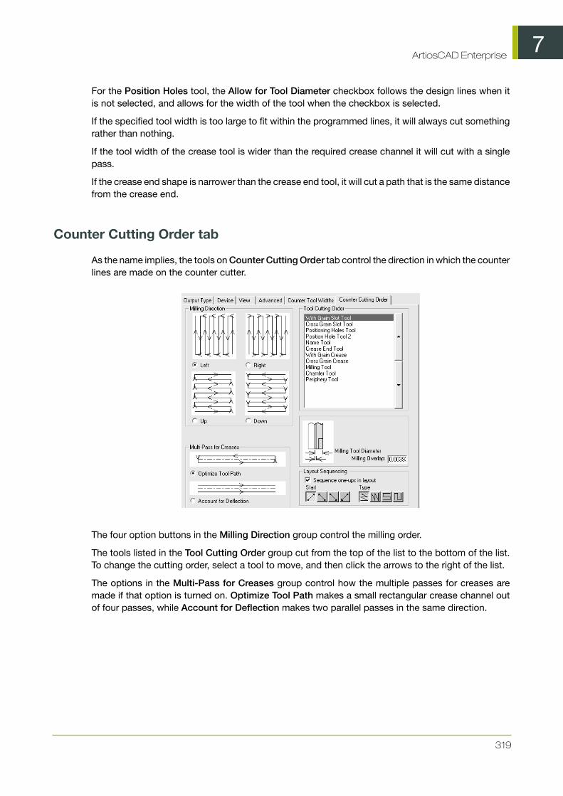
7ArtiosCAD Enterprise
319
For the Position Holes tool, the Allow for Tool Diameter checkbox follows the design lines when itis not selected, and allows for the width of the tool when the checkbox is selected.
If the specified tool width is too large to fit within the programmed lines, it will always cut somethingrather than nothing.
If the tool width of the crease tool is wider than the required crease channel it will cut with a singlepass.
If the crease end shape is narrower than the crease end tool, it will cut a path that is the same distancefrom the crease end.
Counter Cutting Order tab
As the name implies, the tools on Counter Cutting Order tab control the direction in which the counterlines are made on the counter cutter.
The four option buttons in the Milling Direction group control the milling order.
The tools listed in the Tool Cutting Order group cut from the top of the list to the bottom of the list.To change the cutting order, select a tool to move, and then click the arrows to the right of the list.
The options in the Multi-Pass for Creases group control how the multiple passes for creases aremade if that option is turned on. Optimize Tool Path makes a small rectangular crease channel outof four passes, while Account for Deflection makes two parallel passes in the same direction.

7ArtiosCAD Enterprise
320
The value you set in the Milling Overlap field indicates the overlap the milling tools will use when themachine mills lines close to each other. This is to ensure all material is milled correctly.
Grouped Outputs tab
The Grouped Outputs tab, which appears only when the Output Type is set to Grouped Output,lets you group already-defined Outputs into one. For example, with one click, you could save theworkspace, print a spec sheet, export a DDES file, send an email containing a DXF file, and cut asample.
If any of the component Outputs you select go out to a file, they do not need to be configuredto automatically overwrite the file if necessary; Esko ArtiosCAD will prompt for a filename whennecessary.
To add an Output to this Grouped Output, click Add and select it from the list of Outputs; to deleteit, click Delete.
Also, the Scale group on the Output Type tab is unavailable for Grouped Outputs as the scales areset for each component Output.
The Outputs listed are processed in top-down order. To change the position of an Output, select it,and then move it by using the arrows at the side of the list box.
Save before performing outputs uses the current name of the workspace if one is defined. If it is notdefined, Esko ArtiosCAD prompts for the information needed. Save-As before performing outputslets you select a new folder or resource as well as a new filename. Esko ArtiosCAD works with thenew file as soon as it is saved, so any Outputs in this grouped Output will use the new file.
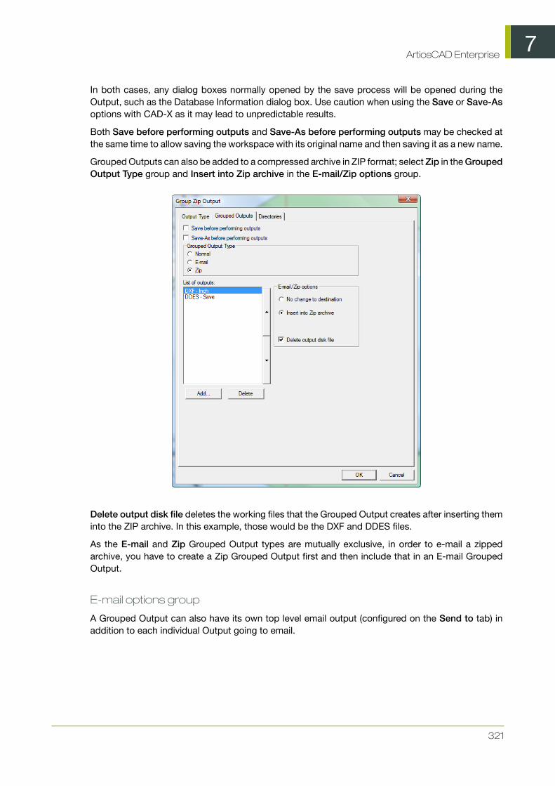
7ArtiosCAD Enterprise
321
In both cases, any dialog boxes normally opened by the save process will be opened during theOutput, such as the Database Information dialog box. Use caution when using the Save or Save-Asoptions with CAD-X as it may lead to unpredictable results.
Both Save before performing outputs and Save-As before performing outputs may be checked atthe same time to allow saving the workspace with its original name and then saving it as a new name.
Grouped Outputs can also be added to a compressed archive in ZIP format; select Zip in the GroupedOutput Type group and Insert into Zip archive in the E-mail/Zip options group.
Delete output disk file deletes the working files that the Grouped Output creates after inserting theminto the ZIP archive. In this example, those would be the DXF and DDES files.
As the E-mail and Zip Grouped Output types are mutually exclusive, in order to e-mail a zippedarchive, you have to create a Zip Grouped Output first and then include that in an E-mail GroupedOutput.
E-mail options group
A Grouped Output can also have its own top level email output (configured on the Send to tab) inaddition to each individual Output going to email.
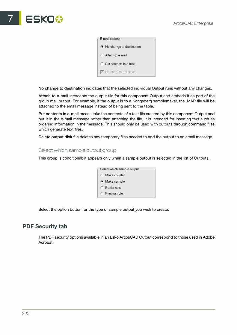
7ArtiosCAD Enterprise
322
No change to destination indicates that the selected individual Output runs without any changes.
Attach to e-mail intercepts the output file for this component Output and embeds it as part of thegroup mail output. For example, if the output is to a Kongsberg samplemaker, the .MAP file will beattached to the email message instead of being sent to the table.
Put contents in e-mail means take the contents of a text file created by this component Output andput it in the e-mail message rather than attaching the file. It is intended for inserting text such asordering information in the message. This should only be used with outputs through command fileswhich generate text files.
Delete output disk file deletes any temporary files needed to add the output to an email message.
Select which sample output group
This group is conditional; it appears only when a sample output is selected in the list of Outputs.
Select the option button for the type of sample output you wish to create.
PDF Security tab
The PDF security options available in an Esko ArtiosCAD Output correspond to those used in AdobeAcrobat.

7ArtiosCAD Enterprise
323
Checking Require a password to open the document requires the recipient of the file to enter apassword when opening the PDF file using Adobe Acrobat Viewer. Enter this password in the Openpassword and Repeat password fields; they must match exactly. There is no way to recover thispassword if it is lost or forgotten.
Checking Use a password to restrict permissions requires the recipient of the file to enter apassword to change how the file is protected. Enter this password in the Open password and Repeatpassword fields; they must match exactly. There is no way to recover this password if it is lost orforgotten.
If both password options are used, the two sets of passwords must be different.
Note: If you forget a password, change the password in Defaults, save the changed Defaults, andthen regenerate the PDF document. It will use the new password.
In the Printing allowed drop-down list box, there are three settings: None, Low Resolution, and HighResolution. None means the recipient may not print the document. Low Resolution allows printing
7ArtiosCAD Enterprise
324
as a bitmap up to 150 dpi. High Resolution allows printing the document at any resolution, and touse high-quality vector output and other advanced printing features if the printer supports them.
In the Changes allowed drop-down list box, there are three choices: None, Page content changesonly, and All changes allowed. None allows no changes in Adobe Acrobat. Page content changesonly restricts changes to what is shown on the page, but prevents other changes such as pagerotation. All changes allowed allows any change.
The recipient of a PDF file created by Esko ArtiosCAD with security options set must use AdobeAcrobat 5.0 or later to open the file.
Note: Esko ArtiosCAD cannot open PDF files with an Open password, nor can it open PDF files thathave restricted permissions and that do not have content copying enabled.
Configuring a PDF Output using Adobe® Acrobat® 5
To configure an Esko ArtiosCAD Output that creates a PDF file using Adobe Acrobat 5, do thefollowing:
1. Install Adobe Acrobat 5 as a custom installation, making sure to install the Acrobat PDFWriter.2. Start Esko ArtiosCAD, open Defaults, and create a new Plot output using the procedures
described earlier in the chapter.3. In the Scale group on the Output Type tab, click To fit one page.4. On the Device tab, set the Driver Type to Windows Driver and select Acrobat PDFWriter in the
Windows Driver drop-down list box. Also set the Orientation to Optimum. The orientation in EskoArtiosCAD works independently from the orientation in the printer driver; you may have to adjustthe settings manually to achieve the desired output.
5. In the Plot File group on the Directories tab, set the extension to .pdf. Make sure to include theperiod before pdf.
6. Click OK and save the defaults.
Later versions of Adobe Acrobat will not work correctly with Esko ArtiosCAD.
Note: Esko ArtiosCAD also has a predefined PDF export and Output that use its native PDF methodwithout requiring Adobe Acrobat 5 to be loaded on the system. These require no special configurationfor use, but the option must be purchased and installed for them to work. If you have Adobe Acrobat5, you can make PDF files in the method described above without having to purchase the PDF optionin Esko ArtiosCAD. However, without purchasing the PDF option, you will not be able to import PDFfiles or use high graphics mode.
Configuring 3D Outputs
3D has its own table in Defaults for Outputs. Shown below is the Artios catalog in Shared Defaults> Outputs-3D.
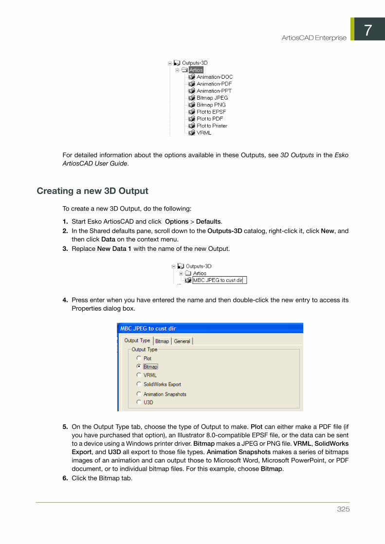
7ArtiosCAD Enterprise
325
For detailed information about the options available in these Outputs, see 3D Outputs in the EskoArtiosCAD User Guide.
Creating a new 3D Output
To create a new 3D Output, do the following:
1. Start Esko ArtiosCAD and click Options > Defaults.2. In the Shared defaults pane, scroll down to the Outputs-3D catalog, right-click it, click New, and
then click Data on the context menu.3. Replace New Data 1 with the name of the new Output.
4. Press enter when you have entered the name and then double-click the new entry to access itsProperties dialog box.
5. On the Output Type tab, choose the type of Output to make. Plot can either make a PDF file (ifyou have purchased that option), an Illustrator 8.0-compatible EPSF file, or the data can be sentto a device using a Windows printer driver. Bitmap makes a JPEG or PNG file. VRML, SolidWorksExport, and U3D all export to those file types. Animation Snapshots makes a series of bitmapsimages of an animation and can output those to Microsoft Word, Microsoft PowerPoint, or PDFdocument, or to individual bitmap files. For this example, choose Bitmap.
6. Click the Bitmap tab.

7ArtiosCAD Enterprise
326
7. In the Save bitmap as group, choose JPEG. Set the other options as desired.8. Click the General tab and enter a directory in the Output directory: field. Set the other options
as desired.
9. Click OK to finish defining the Output.10.Click File > Save, and then click Yes to confirm overwriting shared Defaults.11.The new Output in 3D is ready to use.
There are some slight differences between the options on the tabs in Defaults and those in theOutputs at time of use. For example, the Use OpenGL for bitmaps checkbox on the Bitmap tab whenusing an Output is set in the 3D Rendering Options entry in Startup defaults, not the Output defaults.
There is a fifth type of 3D Output available; Animation Snapshots exports each frame to individualPNG or JPEG files. For example, if you have an 8-frame animation, an Output of this type wouldproduce 8 .JPEG or .PNG files in the same directory. When configuring an Output of this type, on theAnimation tab with Export animation as: set to Bitmaps, the Bitmap Filename Generation groupappears. The options in this group configure how the different filenames are named. The root of eachfilename is the workspace name, and then the Frame separator character is inserted after the name,and either a number or letter is added as a suffix depending on the option chosen.

7ArtiosCAD Enterprise
327
Changing Collada defaults
Using the Collada entry in the Outputs-3D catalog in Defaults creates a .DAE file with .PNG imagesat the current graphics resolution.
To change the settings, do the following:
1. Start ArtiosCAD.2. Click Options > Defaults.3. In the Shared Defaults pane, scroll down to the Outputs-3D catalog and open it by clicking the
plus sign (+) next to it.4. Double-click the Collada entry.5. Click the Collada Options tab.
• In the Graphics resolution group, Use View Settings uses the resolution set in the ViewMode dialog box. Deselect it to enable the drop-down list box that sets the resolution settingmanually.
• PNG and JPEG in the Include bitmaps as group control how the images are stored. SelectJPEG to enable the quality setting.
• In the Save as group, choose to save Collada files as standalone .DAE files or .ZAE archivefiles.
6. Click OK when done setting the options to return to Defaults.7. Click File > Save to save the changes.8. Click Yes to overwrite the existing Defaults.

7ArtiosCAD Enterprise
328
Note:
You may want to create additional Collada entries with different options set for ease of output. Makesure to set the Output Type to Collada on the Output Type tab of the dialog box.
Rule labels
You can define rule labels for special rules that appear in the design when viewing the design, orwhen printing the design, or both. Rule labels display the specific rule type as the generic rule typeplus whatever label you specify.
To configure this, you must add a rule label to the rule definition in the Special Rule Types catalogin Defaults.
Enclosing the fraction in braces causes Esko ArtiosCAD to display it as a real fraction, such as ¼.
To turn on rule labels when working in Esko ArtiosCAD, open the View Mode dialog box, select theRule labels checkbox, and click OK.
Shown below is a hanger hole made from ¼ by ¼ perf with rule labels turned off.

7ArtiosCAD Enterprise
329
Here is the same hanger hole with rule labels turned on:
To turn on rule labels as a function of an output, check the Rule Labels checkbox on the View tabof the output’s properties page.
The defaults for the size and default appearance of the rule labels are stored in the Rule Labels entryin Design defaults.
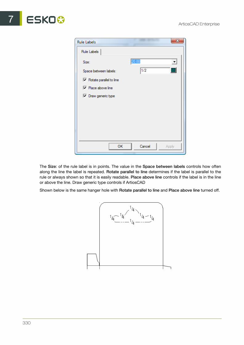
7ArtiosCAD Enterprise
330
The Size: of the rule label is in points. The value in the Space between labels controls how oftenalong the line the label is repeated. Rotate parallel to line determines if the label is parallel to therule or always shown so that it is easily readable. Place above line controls if the label is in the lineor above the line. Draw generic type controls if ArtiosCAD
Shown below is the same hanger hole with Rotate parallel to line and Place above line turned off.
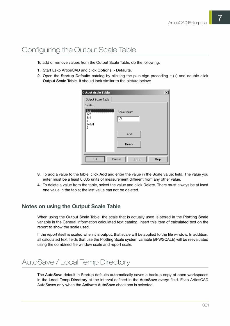
7ArtiosCAD Enterprise
331
Configuring the Output Scale Table
To add or remove values from the Output Scale Table, do the following:
1. Start Esko ArtiosCAD and click Options > Defaults.2. Open the Startup Defaults catalog by clicking the plus sign preceding it (+) and double-click
Output Scale Table. It should look similar to the picture below:
3. To add a value to the table, click Add and enter the value in the Scale value: field. The value youenter must be a least 0.005 units of measurement different from any other value.
4. To delete a value from the table, select the value and click Delete. There must always be at leastone value in the table; the last value can not be deleted.
Notes on using the Output Scale Table
When using the Output Scale Table, the scale that is actually used is stored in the Plotting Scalevariable in the General Information calculated text catalog. Insert this item of calculated text on thereport to show the scale used.
If the report itself is scaled when it is output, that scale will be applied to the file window. In addition,all calculated text fields that use the Plotting Scale system variable (#FWSCALE) will be reevaluatedusing the combined file window scale and report scale.
AutoSave / Local Temp Directory
The AutoSave default in Startup defaults automatically saves a backup copy of open workspacesin the Local Temp Directory at the interval defined in the AutoSave every: field. Esko ArtiosCADAutoSaves only when the Activate AutoSave checkbox is selected.

7ArtiosCAD Enterprise
332
The Local Temp Directory is configured in the Local Temp Directory default in Startup Defaults.
The system TEMP directory is defined by an environment variable. See your system administrator, orrefer to your operating system documentation for more information on changing the system TEMPdirectory.
To set your own TEMP directory, select the Specify option and browse for the desired directory.Everyone must have write access to that directory. The Local Temp Directory must be on the currentmachine - it may not be set to a network drive.
The AutoSave timer is NOT active when:
• a dialog box is open• when the Rebuild Playback tool is in use• when the Interact window is open.
The AutoSave file is named BCKxxxxx.AAS, where xxxxx is a random number, and AAS stands forArtiosCAD Auto Save.
No database synchronization is done with the AutoSave file, nor is it saved in the database.
Recovering AutoSave files
The first time Esko ArtiosCAD starts after an improper termination, the AutoSave Recovery dialogbox will appear listing the workspaces for which AutoSave files exist.

7ArtiosCAD Enterprise
333
Check the checkboxes next to each file to recover and click OK. The AutoSave files will be restoredfor the selected files; SAVE the workspaces once they are open. AutoSave files that are not selectedfor restoration are deleted automatically.
Revision Disk File Format in Revision History
The Revision History feature of Esko ArtiosCAD relies on changing the name of files as they arestored on the hard drive. How file name is changed is controlled by Options > Defaults > Startupdefaults > Revision Disk File Format.
For example, consider a file called FILE. If you choose the first option, Don’t put revision extensionon latest revision, and create a new revision, then the latest revision becomes FILE and the originalbecomes FILE_~. If you then make a new revision, then the latest file will still be FILE, the original willbe FILE_~, and the first revision from the original will be FILE_A. In this case the latest FILE wouldalso be FILE_B, but the _B extension will not be visible; if you open other revisions they will warnyou that the latest revision is FILE_B.
If you choose the second option, Don’t put revision extension on first revision, then each newrevision gets appended in sequence: the original is and will always be FILE, the second revision will
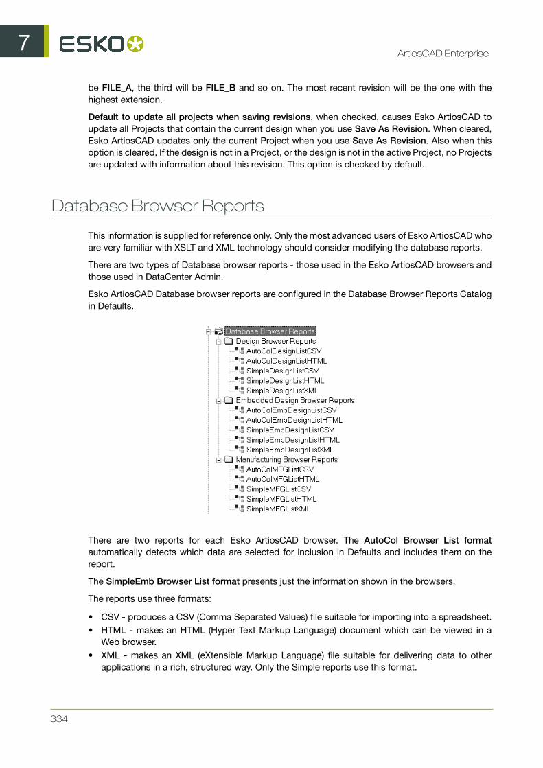
7ArtiosCAD Enterprise
334
be FILE_A, the third will be FILE_B and so on. The most recent revision will be the one with thehighest extension.
Default to update all projects when saving revisions, when checked, causes Esko ArtiosCAD toupdate all Projects that contain the current design when you use Save As Revision. When cleared,Esko ArtiosCAD updates only the current Project when you use Save As Revision. Also when thisoption is cleared, If the design is not in a Project, or the design is not in the active Project, no Projectsare updated with information about this revision. This option is checked by default.
Database Browser Reports
This information is supplied for reference only. Only the most advanced users of Esko ArtiosCAD whoare very familiar with XSLT and XML technology should consider modifying the database reports.
There are two types of Database browser reports - those used in the Esko ArtiosCAD browsers andthose used in DataCenter Admin.
Esko ArtiosCAD Database browser reports are configured in the Database Browser Reports Catalogin Defaults.
There are two reports for each Esko ArtiosCAD browser. The AutoCol Browser List formatautomatically detects which data are selected for inclusion in Defaults and includes them on thereport.
The SimpleEmb Browser List format presents just the information shown in the browsers.
The reports use three formats:
• CSV - produces a CSV (Comma Separated Values) file suitable for importing into a spreadsheet.• HTML - makes an HTML (Hyper Text Markup Language) document which can be viewed in a
Web browser.• XML - makes an XML (eXtensible Markup Language) file suitable for delivering data to other
applications in a rich, structured way. Only the Simple reports use this format.
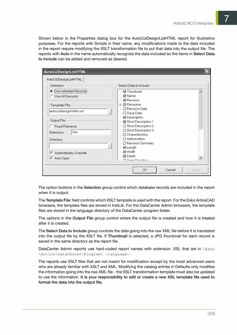
7ArtiosCAD Enterprise
335
Shown below is the Properties dialog box for the AutoColDesignListHTML report for illustrativepurposes. For the reports with Simple in their name, any modifications made to the data includedin the report require modifying the XSLT transformation file to put that data into the output file. Thereports with Auto in the name automatically recognize the data included so the items in Select Datato Include can be added and removed as desired.
The option buttons in the Selection group control which database records are included in the reportwhen it is output.
The Template File: field controls which XSLT template is used with the report. For the Esko ArtiosCADbrowsers, the template files are stored in InstLib. For the DataCenter Admin browsers, the templatefiles are stored in the language directory of the DataCenter program folder.
The options in the Output File group control where the output file is created and how it is treatedafter it is created.
The Select Data to Include group controls the data going into the raw XML file before it is translatedinto the output file by the XSLT file. If Thumbnail is selected, a JPG thumbnail for each record issaved in the same directory as the report file.
DataCenter Admin reports use hard-coded report names with extension .XSL that are in \Esko\Artios\DataCenter\Program\ <language> .
The reports use XSLT files that are not meant for modification except by the most advanced userswho are already familiar with XSLT and XML. Modifying the catalog entries in Defaults only modifiesthe information going into the raw XML file - the XSLT transformation template must also be updatedto use the information. It is your responsibility to edit or create a new XSL template file used toformat the data into the output file.
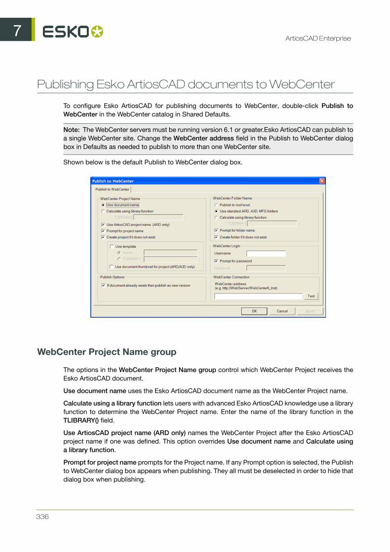
7ArtiosCAD Enterprise
336
Publishing Esko ArtiosCAD documents to WebCenter
To configure Esko ArtiosCAD for publishing documents to WebCenter, double-click Publish toWebCenter in the WebCenter catalog in Shared Defaults.
Note: The WebCenter servers must be running version 6.1 or greater.Esko ArtiosCAD can publish toa single WebCenter site. Change the WebCenter address field in the Publish to WebCenter dialogbox in Defaults as needed to publish to more than one WebCenter site.
Shown below is the default Publish to WebCenter dialog box.
WebCenter Project Name group
The options in the WebCenter Project Name group control which WebCenter Project receives theEsko ArtiosCAD document.
Use document name uses the Esko ArtiosCAD document name as the WebCenter Project name.
Calculate using a library function lets users with advanced Esko ArtiosCAD knowledge use a libraryfunction to determine the WebCenter Project name. Enter the name of the library function in theTLIBRARY() field.
Use ArtiosCAD project name (ARD only) names the WebCenter Project after the Esko ArtiosCADproject name if one was defined. This option overrides Use document name and Calculate usinga library function.
Prompt for project name prompts for the Project name. If any Prompt option is selected, the Publishto WebCenter dialog box appears when publishing. They all must be deselected in order to hide thatdialog box when publishing.

7ArtiosCAD Enterprise
337
Create project if it does not exist creates the WebCenter Project named using the options selectedin the previous fields if it does not already exist. If this option is deselected and the WebCenter Projectdoes not exist, when Esko ArtiosCAD tries to publish a document into that WebCenter Project, anerror will occur.
Use template lets you specify the template to use to create the Project. Enter its name in the Namefield or enter the name of the library function used to calculate the name in the TLIBRARY() field.
Use document thumbnail causes WebCenter to use the thumbnail for the single design or 3Ddocument as the Project thumbnail.
Publish Options group
If document already exists then publish as new version controls what happens when a documentwith the same name as the document being published already exists in the same folder in theWebCenter Project. When this option is selected, the document being published is treated as a newrevision of the document already in the WebCenter Project. When this option is not selected and adocument exists with the same name as one being published, an error will occur.
WebCenter Folder Name group
The options in the WebCenter Folder Name group control where in the WebCenter Project the EskoArtiosCAD document is placed once it is published.
Publish to root level puts the Esko ArtiosCAD document in the default folder in the Project. Securityon this folder is inherited from the WebCenter Project security settings.
Use standard ARD, A3D, MFG folders uses folders with those names for Esko ArtiosCAD documentswith those filename extensions. Single designs would go into a folder called ARD, 3D documentsinto A3D, and manufacturing files into MFG.
Calculate using a library function lets users with advanced Esko ArtiosCAD knowledge use a libraryfunction to determine the folder name. Enter the name of the library function in the TLIBRARY() field.
Prompt for folder name prompts for the folder name. If any Prompt option is selected, the Publishto WebCenter dialog box appears when publishing. They all must be deselected in order to hide thatdialog box when publishing.
Create folder if it does not exist creates the folder named using the options selected in the previousfields if it does not already exist. If this option is deselected and the folder does not exist, when EskoArtiosCAD tries to publish a document into that folder, an error will occur.
WebCenter Login group
The WebCenter system administrator must provide a username and password for the account EskoArtiosCAD will use to publish documents to WebCenter. Enter the username in the Username field.Prompt for password causes the Esko ArtiosCAD user to have to enter a password when publishing.Deselecting this option causes the Password field to become available. If you specify a username

7ArtiosCAD Enterprise
338
and a password, they will be automatically entered in the Publish to WebCenter dialog box whenpublishing.
WebCenter Connection group
Enter the URL for the WebCenter server in the WebCenter address field.
Note: Esko ArtiosCAD may only publish to the WebCenter site listed in this field. To publish to anotherWebCenter site, change this field as needed.
Test tests the connection to the WebCenter server. The test is successful only if you receive amessage that the WebCenter Web-API was properly installed. Any other response means the testfailed.
Graphic PDF file rotation import option
A PDF file can contain an internal flag to indicate if the document is rotated or not. ArtiosCAD hasignored this setting until version 7.35. In Options > Defaults > Shared Defaults > Startup defaults> PDF Options is the Honor Acrobat Rotation checkbox. To have ArtiosCAD respect this flag whenimporting a PDF file as graphics, enable this checkbox. The checkbox is not selected by default, andhas no effect for PDF files imported as lines.
Setting CAPE/TOPS Defaults
Before you use the palletizing features, you must set the CAPE/TOPS Defaults by doing the following:
1. Start ArtiosCAD.
2. Click Options > Defaults.
3. In the list of Shared defaults, scroll down to the Palletization catalog and open it by clicking theplus sign (+) next to it.
4. Double-click CAPE/TOPS Defaults.
The CAPE Defaults dialog box opens as shown below.

7ArtiosCAD Enterprise
339
5. Set the options in the dialog box as desired.
a) If you are using CAPE/TOPS in client/server mode, select Client/Server and enter the UserID for CAPE/TOPS in the field provided. If you are using it in workstation/standalone mode,leave this field empty.

7ArtiosCAD Enterprise
340
b) Choose a default pallet from the drop-down list box in the Default Pallet group.c) Set the Maximum pallet height and Maximum pallet weight appropriately using inches and
pounds or millimeters and kilograms.d) To not see the waste areas of the layout and see only the designs in CAPE/TOPS, check Output
to CAPE/TOPS as stripped.e) To calculate the caliper from the board elements instead of using the caliper defined by the
board code, check Calculate True Caliper from Medium and Liners.f) Set an Import pallet tolerance for use when exchanging design data between ArtiosCAD
and CAPE/TOPS. As the outer dimensions of the CAPE/TOPS pack type and the ArtiosCADstandard may not match, the tolerance will make it easier to generate pallet loads.
g) In the Arrange/Design Options group, set the default amount of slack and the defaultmaximum package size.
h) In the Number of primary packages group, set the minimum and maximum number of primarypackages in the secondary package.
i) Set Round to nearest 1/16th as desired. This works in Inches mode only.j) Click OK to return to Defaults when you are done setting the CAPE/TOPS Defaults.
6. Click File > Save to save the changes.
7. Click Yes to confirm the saving of the changes to Defaults and return to ArtiosCAD.
Setting DWG/DXF Options
DWG/DXF Options in the Startup defaults catalog is where you:
• set whether or not to use third-party import libraries• map font names in DWG/DXF files to Windows TrueType fonts.
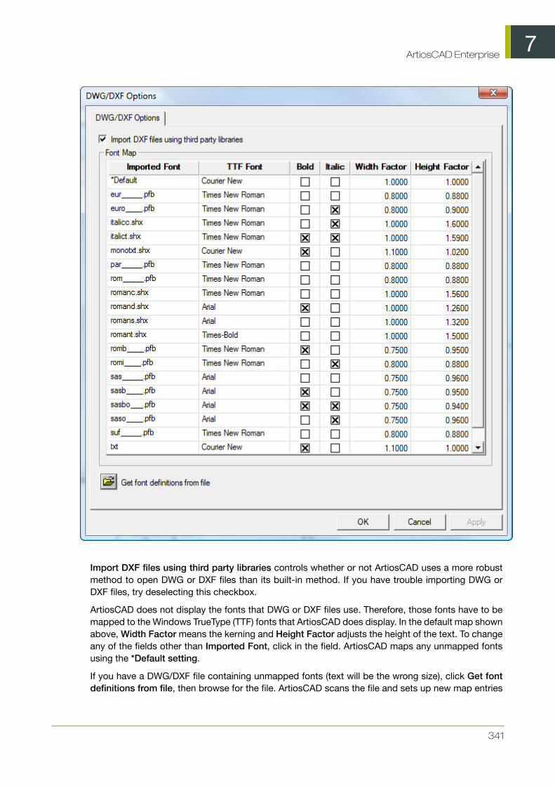
7ArtiosCAD Enterprise
341
Import DXF files using third party libraries controls whether or not ArtiosCAD uses a more robustmethod to open DWG or DXF files than its built-in method. If you have trouble importing DWG orDXF files, try deselecting this checkbox.
ArtiosCAD does not display the fonts that DWG or DXF files use. Therefore, those fonts have to bemapped to the Windows TrueType (TTF) fonts that ArtiosCAD does display. In the default map shownabove, Width Factor means the kerning and Height Factor adjusts the height of the text. To changeany of the fields other than Imported Font, click in the field. ArtiosCAD maps any unmapped fontsusing the *Default setting.
If you have a DWG/DXF file containing unmapped fonts (text will be the wrong size), click Get fontdefinitions from file, then browse for the file. ArtiosCAD scans the file and sets up new map entries

7ArtiosCAD Enterprise
342
with which you can then configure as desired. It then stores FontMap.XML in ClientLIb whichyou can copy between machines as needed.
Note: ArtiosCAD does not use font mapping if Import DXF files using third party libraries is notchecked.