Embed Size (px)
Citation preview

Petrol Leaf VacuumArtikel-Nr.: Ident-Nr.: 01014

Komponenten / Ersatzteile
Position Artikel-Nr. Beschreibung
1 343600001001 carburettor
3 343600001003 air filter cover
4 343600001004 air filter
11 343600001010 pump
13 343600001012 throttle cable
19 343600001060 switch
28 343600001026 ISOLATOR
30 343600001028 tank lid
38 343600001036 nozzle
39 343600001061 blower bag
48 343600001045 fan wheel
53 343600001050 spray valve
54 343600001051 louver
55 343600001052 suction tube
56 343600001053 SCREW
64 343600001064 starter
65 343600001065 spark coil
66 343600001066 shoulder strap
67 343600001067 spark plug
68 343600001068 sailing

� Operating InstructionsGarden Blower Vac
SBV320034.360.01
Art.-No.: 519920 I.-No.: 01014
Anleitung SBV 3200 10.01.2005 9:37 Uhr Seite 1

2
Meaning of symbols marked on the product
Read the user manual before using the machine
Wear safety goggles to protect your eyes
Wear ear protector to protect against noise
Wear dust mask to protect against dust
Wear gloves to protect your hands
Wear safety boots to protect agains electric shock
� Please pull out page 2
Anleitung SBV 3200 10.01.2005 9:37 Uhr Seite 2

3
12
345
6
7
8
9
10
13
15
11 12
16
14
17
18
1
Anleitung SBV 3200 10.01.2005 9:37 Uhr Seite 3

4
GB
GENERAL SAFETY RULES• WHAT NOT TO DOREAD YOUR USER MANUAL AND ALLSUPPLEMENTS (IF ANY ENCLOSED)THOROUGHLY BEFORE OPERATING YOURUNIT.1. WEAR CLOSE FITTING, TOUGH WORK
CLOTHING that will provide protection/withoutrestricting your movements, such as long slacksor trousers, safety work shoes, heavy duty workgloves, hard hat, a safety face shield, or safetyglasses for eye protection and a good grade ofear plugs or other sound barriers for hearingprotection.
2. REFUEL IN A SAFE PLACE. Open fuel capslowly to release any pressure which may haveformed in fuel tank. Always wipe unit of fuel or oilspills before starting. To prevent a fire hazard,move at least 10 feet (3 meters) from fueling areabefore starting.
3. TURN UNIT OFF before setting it down, and alsobefore installing or removing attachments.
4. KEEP ALL SCREWS AND FASTENERS TIGHTand the unit in good operating condition. Neveroperate this equipment if it is improperly adjustedor not completely and securely assembled.
5. KEEP HANDLES DRY, clean and free of fuelmixture.
6. STORE EQUIPMENT AWAY FROM POSSIBLEIGNITION SOURCES, such as gas-poweredwater heaters, clothes dryers, or oil-firedfurnaces, portable heaters, etc.
7. ALWAYS KEEP the engine free of debris build-up.
8. OPERATION OF EQUIPMENT should always berestricted to mature and properly instructedindividuals.
9. ALL PERSONS WITH RESPIRATORYPROBLEMS and persons operating blower invery dusty environments, should wear a dustparticle mask at all times. Paper dust masks areavailable at most paint and hardware stores.
• WHAT NOT TO DO
WARNING: DO NOT USE ANY OTHER FUEL thanthat recommended in your manual. Always followinstructions in the Fuel and Lubrication section of thismanual. Never use gasoline unless it is properlymixed with 2-stroke engine lubricant. Permanentdamage to engine will result, voiding manufacturer’swarranty.
1. DO NOT SMOKE while refueling or operatingequipment.
2. DO NOT OPERATE UNIT WITHOUT AMUFFLER and properly installed muffler shield.
3. DO NOT TOUCH or let your hands or body comein contact with a hot muffler or spark plug wire.
4. DUE TO THE DANGER of exhaust fumes, neveroperate blower in a confined or poorly ventilatedarea.
5. NEVER POINT BLOWER in the direction ofpeople, animals, buildings, automobiles, orwindows, etc.
6. DO NOT operate unit without inlet cover installedto prevent contact with impeller.
7. DO NOT set a hot engine down where flammablematerial is present.
8. DO NOT OPERATE UNIT FOR PROLONGEDPERIODS. Rest periodically.
9. DO NOT OPERATE UNIT WHILE UNDER THE INFLUENCE OF ALCOHOL OR DRUGS.
WARNING: DO NOT ADD, REMOVE OR ALTERANY COMPONENTS OF THIS PRODUCT. Doing socould cause personal injury and/or damage the unitvoiding the manufacturer’s warranty.
10. DO NOT operate your unit near or aroundflammable liquids or gases whether in or out ofdoors. An explosion and/or fire may result.
11. DO NOT WEAR loose clothing, scarfs, neckchains, unconfined long hair, and the like. Doingso could cause injury associated with objectsbeing drawn into the rotating parts. Tie up longhair and fasten it, for example with a head scarf,cap, helmet, etc.
12. DO NOT refuel a running engine or an enginethat is hot
Layout (Fig. 1)
1. Rear Handle2. Throttle Trigger3. Throttle Lock4. On/Off Switch5. Front Handle6. Muffler Cover (Exhaust)7. Fuel Tank Window8. Fuel Cap9. Starter Handle
10. Air Filter Cover11. Vacuum/Blower Tube12. Choke Lever13. Spark Plug Wire / Spark Plug14. Vacuum/Blower Slide15. Primer Bulb16. Harness17. Vacuum Bag18. Speed Cleaner Head
Anleitung SBV 3200 10.01.2005 9:37 Uhr Seite 4

5
GB
2. Technical data
Engine . . . . . . . . . . . . . . . . . . . . . . . . . . . . . . .24 cm3
Max. Air Velocity . . . . . . . . . . . . . . . . . . . .ca. 40 m/sMax. Air Volume . . . . . . . . . . . . . . . . . . . . . .240 m3/hMax. Engine Speed . . . . . . . . . . . . . . . . .11,500 min-1
Collection Bag . . . . . . . . . . . . . . . . . . . . . . . . .55 LitreMulching Ratio . . . . . . . . . . . . . . . . . . . . . . . . . . .10:1Fuel Capacity . . . . . . . . . . . . . . . . . . . . . . . . . .700 mlWeight . . . . . . . . . . . . . . . . . . . . . . . . . . . . . . . .6.4 kgMaximum Enquine Performance . . . . . . . .0.8 kWNoise . . . . . . . . . . . . . . . . . . . . . . . . . . . . .108 dB(A)Vibration . . . . . . . . . . . . . . . . . . . . . . . . . . .13.7 m/s2
3. BLOWER ATTACHMENT ASSEMBLYINSTRUCTIONS
1. Release the screws (A) and remove the screw (B).Insert blower tube (C) into the blower housing andreplace screw (B). Tighten screws (A). (Fig. 1A)
2. Insert speed cleaner head (D) to the tube (C). (Fig.1B)
• HARNESS INSTALLATION Attach the 2 harness clips to the2 links in the blower handle.(Fig. 2)
• VACUUM ATTACHMENTASSEMBLY INSTRUCTIONS
To install vacuum bag:Pull the slide (A) forward and fit bag (B) into thevacuum housing. (See Fig. 3)
NOTICE: Vacuum bag installationThe vacuum bag connection tube MUST be scurelyand correctly fitted to the vacuum housing (see fig. 3of the instructions) prior to the operation. To ensurethe tube is in place correctly, first line up with theindentations either side of the opening. Push theconnector into place and turn to the right until a clickis heard and the unit locks securely.
This is a safety feature and if the connector is not inplace the blower vac will not start.
The vacuum bag can now be fitted over the open endof the connection tube and secured with the velcrostrap.
FUEL AND LUBRICATION
• FUELUse regular grade unleaded gasoline mixed with 40:1custom 2-stroke engine oil for best results.
WARNING: Never use straight gasoline in your unit.This will cause permanent engine damage and voidthe manufacturer’s warranty for that product. Neveruse a fuel mixture that has been stored for over 90days.
WARNING: Use only Class I 2-stroke oil suitable forair-cooled engines.
• MIXING FUELMix the fuel with 2-stroke oil in a suitable container.Shake the container to ensure that it is properlymixed.
• FUEL AND LUBRICATION
• RECOMMENDED FUELSSome conventional gasolines are being blended withoxygenates such as alcohol or an ether compound tomeet clean air standards. Your engine is designed tooperate satisfactorily on any gasoline intended forautomotive use including oxygenated gasolines.
Gasoline andOil Mix 40:1
Fig. 2
Fig. 1A Fig. 1B
A
BC
D
C
Fig. 3
B
A
Anleitung SBV 3200 10.01.2005 9:37 Uhr Seite 5

6
GB
OPERATING INSTRUCTIONS
• STARTING A COLD ENGINEFill fuel tank with proper gas and oil mixture. SeeFuel and Lubrication. Set unit on ground so that itrests on housing feet.1. Pull the throttle trigger (A). (It will auto lock) Fig.
4A.2. Prime the carburetor. Pump the primer bulb (C) 10
times (Fig. 4B).3. Your unit is designed with a 2 position choke (D):
START “ ” and RUN “ ”. Move choke lever toSTART “ ” position (Fig. 4C).
4. Grip handle firmly .5. Pull starter rope out a short way until resistance is
felt (approximately 100mm). Pull starter ropequickly and evenly until engine starts or attemptsto run.Once engine starts, warm up at full throttlefor 10 seconds and release throttle.
6. Push down the throttle lock (B), the throttle trigger(A) will back to the nomal position. (Fig. 4A)
7. Move the choke to RUN “ ” position (Fig. 4E).
NOTE: If engine fails to start after repeated attempts,refer to Troubleshooting section.NOTE: Always pull starter rope straight out. Pullingstarter at an angle will cause rope to rub against theeyelet. This friction will cause the rope to fray andwear more quickly. Always hold starter handle whenrope retracts. Never allow rope to snap back fromextended position. This could cause rope to snag orfray and also damage the starter assembly.
• STOPPING THE ENGINE
Emergency Stopping Procedure. When it isnecessary to stop blower engine immediately,DEPRESS the switch to stop.
Normal Stopping Method. For normal stopping,push down the throttle lock, the throttle trigger willback to the nomal position and allow engine to returnto idle speed. Then DEPRESS and HOLD the “OFF”switch until the engine stops completely.
• STARTING A WARM ENGINE (Engine has beenstopped for no more than 15-20 minutes)
1. Pull starter rope again. Engine should start withONE or TWO pulls. If engine fails to start after 6pulls, repeat steps 2 through 6 (see Starting a coldengine).
2. If engine does not start, or starts and then stopsafter 5 rope pulls, follow procedure “STARTING ACOLD ENGINE”.
• BLOWER OPERATIONS (Fig. 5)Your blower is designed to easily remove debris frompatios, walkways, lawns, bushes, etc., and manyhard to reach areas where debris may accumulate.
WARNING: Because of flying debris, always wearapproved shielded safety glasses or face shield whenoperating blower.
Before using your blower, review Safety Precautionsin your User Manual, and all regulations for operationof the unit. These precautions and regulations are foryour protection.
CAUTION: Hold the blower so that hot exhaust doesnot damage clothing and is not inhaled by operator.
DO NOT operate the blower with other people oranimals in the immediate vicinity. Allow a minimum of30 feet (9 meters) between operator and otherpeople or animals.We recommend that a face mask be worn whenoperating blower in dusty areas.Stand away from the debris, at a distance that willeasily allow you to control the direction of blowndebris. Never blow debris in direction of bystanders.To control velocity of airstream, blower can beoperated at any speed between idle and full throttle.Experience with the unit will help you determine theamount of airflow necessary for each application.
• VACUUM OPERATIONS
WARNING: NEVER OPERATE VACUUM WITHOUTVACUUM BAG PROPERLY ATTACHED, ASFLYING DEBRIS COULD CAUSE INJURY TOOPERATOR AND BYSTANDERS. ALWAYS MAKESURE VACUUM BAG ZIPPER IS CLOSEDBEFORE OPERATING UNIT.
Fig. 5
Fig. 4D Fig. 4E
Fig. 4A
C
A
Fig. 4B Fig. 4C
D
D
B
Anleitung SBV 3200 10.01.2005 9:38 Uhr Seite 6

7
GB
Do not vacuum hot or burning materials (e.g. hotash, glowing cigarettes) from outdoor fireplaces orbarbecue pits. always wait for these materials to becool enough. Do not vacuum lighted smokingmaterial such as discarded cigars or cigarettes. Donot operate unit near open flame.
CAUTION: This unit is designed to vacuum up debrissuch as leaves, small bits of paper, small twigs,weeds, grass clippings, etc. Do not use this unit forany other purpose.
Do not attempt to vacuum rocks, broken glass,bottles, tin cans or other such objects. Damage toimpeller and unit as well as operator injury couldresult.If vacuum tube is level with power unit horizontal,rocks or large objects may be drawn into tube,damaging the impeller.To Operate Vacuum:1. Follow correct starting procedures as explained in
this manual.2. Allow engine to return to idle. Put the shoulder
harness on so the strap is over your rightshoulder. Put the vacuum bag strap on so it isover your left shoulder.
CAUTION: Do not allow shoulder harness to cover,block, or come in contact with exhaust outlet duringoperation. The muffler generates heat and couldburn, melt, or damage harness strap.
3. Place your left hand on the top handle and righthand on side handle as shown (Fig. 6).
4. Swing unit side to side to vacuum debris.
CAUTION: To avoid clogging vacuum tube. DO NOTFORCE OR PLACE SUCTION TUBE INTO A PILEOF DEBRIS.
• VACUUM TUBE CLOGGINGTo Unclog Vacuum Tube:1. Turn engine “OFF”. Promptly compress vacuum
bag while it is still inflated, expelling air out of the
suction tube.This reverse airflow is usually sufficient to dislodgemost obstructions. If the obstruction cannot becleared by compressing vacuum bag, follow thisprocedure:2. Remove and inspect vacuum tubes. 3. Carefully clean out nozzle. 4. Reinstall vacuum tubes.
AIR FILTER
CAUTION: NEVER operate blower without the airfilter or dust and dirt will be sucked into the engineand damage it. The air filter must be kept clean. If itbecomes damaged, install a new filter.
To Clean Air Filter:1. Remove 2 screws (A) holding air filter cover in
place, remove cover (B) and lift filter (C) fromcover (Fig. 7A and B).
2. Wash filter in soap and water. DO NOT USEGASOLINE!
3. Air dry filter.4. Reinstall air filter and air filter cover.NOTE: Replace filter if frayed, torn, damaged orunable to be cleaned.
• CARBURETOR ADJUSTMENTThe carburetor was pre-set at the factory foroptimum performance. If further adjustments arenecessary, please take your unit to the nearestprofessional.
• SPARK PLUG1. Spark plug gap = .025 in.
(.635mm) (Fig. 8).2. Torque to 105 to 130 inch
pounds (12 to 15 N•m). Connectspark plug boot.
• VACUUM BAG CLEANINGA dirty bag will obstruct airflow, thereby reducingvacuum efficiency.To Clean Bag:1. Detach vacuum bag from unit.2. Open zipper and remove contents.3. Turn bag INSIDE OUT and shake vigorously.
This procedure should be performed on a regularbasis.
Fig. 7A Fig. 7B
C
B
A B
.025 in.(.635mm)
Fig. 8
Fig. 6
Anleitung SBV 3200 10.01.2005 9:38 Uhr Seite 7
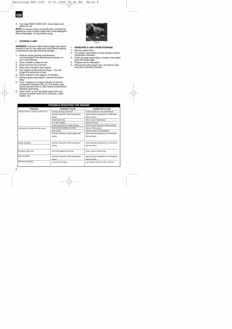
4. Turn bag RIGHT SIDE OUT, close zipper andattach to unit.
NOTE: If vacuum bag is unusually dirty, it should bewashed by hand in warm water with a mild detergent.Rinse thoroughly. Let dry before using.
• STORING A UNIT
WARNING: Failure to follow these steps may causevarnish to form in the carburetor and difficult startingor permanent damage following storage.
1. Perform all the general maintenancerecommended in the Maintenance Section ofyour User Manual.
2. Clean outside surface of unit.3. Drain fuel from the fuel tank.4. After fuel is drained, start engine.5. Run engine at idle until unit stops. This will
purge the carburetor of fuel. 6. Allow engine to cool (approx. 5 minutes).7. Using a spark plug wrench, remove the spark
plug.8. Pour 1 teaspoon of clean 2-stroke oil into the
combustion chamber (Fig. 9). Pull starter ropeslowly several times to coat internal components.Replace spark plug.
9. Store unit in a cool, dry place away from anysource of ignition such as an oil burner, waterheater, etc.
• REMOVING A UNIT FROM STORAGE1. Remove spark plug.2. Pull starter rope briskly to clear excess oil from
combustion chamber.3. Clean and gap spark plug or install a new spark
plug with proper gap.4. Prepare unit for operation.5. Fill fuel tank with proper fuel / oil mixture. See
Fuel and Lubrication Section.
8
GB
TROUBLE SHOOTING THE ENGINEPROBLEM
Unit won’t start or starts but will not run.
Unit starts, but engine has low power.
Engine hesitates.
No power under load.
Runs erratically.
Smokes excessively.
PROBABLE CAUSE
Incorrect starting procedures.
Incorrect carburetor mixture adjustment
setting.
Fouled spark plug
Fuel filter plugged.
Vacuum bag tube isn’t fitted correctly.
Incorrect lever position on choke.
Dirty air filter.
Incorrect carburetor mixture adjustment
setting.
Incorrect carburetor mixture adjustment
setting.
Incorrectly gapped spark plug.
Incorrect carburetor mixture adjustment
setting.
Incorrect fuel mixture.
CORRECTIVE ACTION
Follow instructions in the User Manual.
Have carburetor adjusted by an Authorized
Service Center.
Clean / gap or replace plug.
Replace fuel filter.
Check vacuum bag tube is fitted correctly.
Move to RUN position.
Remove, clean and reinstall filter.
Have carburetor adjusted by an Authorized
Service Center.
Have carburetor adjusted by an Authorized
Service Center.
Clean / gap or replace plug.
Have carburetor adjusted by an Authorized
Service Center.
Use properly mixed fuel (40:1 mixture).
Fig. 9
Anleitung SBV 3200 10.01.2005 9:38 Uhr Seite 8

9
D erklärt folgende Konformität gemäß EU-Richtlinie und Normen für Artikel
� declares conformity with the EU Directive and standards marked below for the article
F déclare la conformité suivante selon la directive CE et les normes concernant l’article
� verklaart de volgende conformiteit in overeen-stemming met de EU-richtlijn en normen voor het artikel
E declara la siguiente conformidad a tenor de la directiva y normas de la UE para el artículo
P declara a seguinte conformidade de acordo com a directiva CE e normas para o artigo
S förklarar följande överensstämmelse enl. EU-direktiv och standarder för artikeln
ilmoittaa seuraavaa Euroopan unionin direkti-ivien ja normien mukaista yhdenmukaisuutta tuotteelle
erklærer herved følgende samsvar med EU-direktiv og standarder for artikkel
� заявляет о соответствии товара следующим директивам и нормам EC
� izjavljuje sljedeću uskladjenost s odredbama i normama EU za artikl.
declarå urmåtoarea conformitate cu linia direc-
toare CE µi normele valabile pentru articolul.
� ürün ile ilgili olarak AB Yönetmelikleri ve
Normlar∂ gere©ince aµa©∂daki uygunluk aç∂kla
mas∂n∂ sunar.
� ‰ËÏÒÓÂÈ ÙËÓ ·ÎfiÏÔ˘ıË Û˘Ìʈӛ· Û‡Ìʈӷ Ì ÙËÓ √‰ËÁ›· ∂∂ Î·È Ù· ÚfiÙ˘Ô ÁÈ· ÙÔ ÚÔ˚fiÓ
I dichiara la seguente conformità secondo la direttiva UE e le norme per l’articolo
attesterer følgende overensstemmelse i henhold til EU-direktiv og standarder for produkt
� prohlašuje následující shodu podle směrnice EU a norem pro výrobek.
H a következő konformitást jelenti ki a termékek-re vonatkozó EU-irányvonalak és normák szerint
� pojasnjuje sledečo skladnost po smernici EU in normah za artikel.
� deklaruje zgodność wymienionego poniżej artykułu z następującymi normami na podstawie dyrektywy WE.
� vydáva nasledujúce prehlásenie o zhode podľa smernice EÚ a noriem pre výrobok.
� деклаpиpа следното съответствие съгласно диpективите и ноpмите на ЕС за пpодукта.
Landau/Isar, den 03.11.2004Landauer
Produkt-Management
Garden Blower Vac SBV 3200
BrunhölzlLeiter Produkt-Management
ISC GmbHEschenstraße 6D-94405 Landau/Isar
Konformitätserklärung
98/37/EG
73/23/EWG_93/68/EEC
97/23/EG
89/336/EWG_93/68/EEC
90/396/EWG
89/686/EWG
87/404/EWG
R&TTED 1999/5/EG
2000/14/EG:
95/54/EG:
97/68/EG:
x
x
xLWM = xxx dB; LWA = 108 dB
P = xxxx kW; L/Ø = xxxx cm
Art.-Nr.: 34.360.01 I.-Nr.: 01014 Archivierung: 3436000-02-4160270-ESubject to change without notice
EN ISO 14982
Anleitung SBV 3200 10.01.2005 9:38 Uhr Seite 9

GARANTIEURKUNDEAuf das in der Anleitung bezeichnete Gerät geben wir 2 JahreGarantie, für den Fall, dass unser Produkt mangelhaft sein sollte.Die 2-Jahres-Frist beginnt mit dem Gefahrenübergang oder derÜbernahme des Gerätes durch den Kunden. Voraussetzung fürdie Geltendmachung der Garantie ist eine ordnungsgemäßeWartung entsprechend der Bedienungsanleitung sowie die be-stimmungsgemäße Benutzung unseres Gerätes.
Selbstverständlich bleiben Ihnen die gesetzlichen Gewähr-leistungsrechte innerhalb dieser 2 Jahre erhalten. Die Garan-tie gilt für den Bereich der Bundesrepublik Deutschland oder derjeweiligen Länder des regionalen Hauptvertriebspartners als Er-gänzung der lokal gültigen gesetzlichen Vorschriften. Bitte be-achten Sie Ihren Ansprechpartner des regional zuständigen Kun-dendienstes oder die unten aufgeführte Serviceadresse.
ISC GmbH · International Service CenterEschenstraße 6 · D-94405 Landau/Isar (Germany)
Info-Tel. 0180-5 120 509 • Telefax 0180-5 835 830Service- und Infoserver: http://www.isc-gmbh.info
EH 11/2004
� Technical specifications subject to change
�The reprinting or reproduction by any other means, in whole or inpart, of documentation and papers accompanying products ispermitted only with the express consent of ISC GmbH.
Sovereign Customer Helpline 0044 (0) 151 649 1500
Contact for Warranty repairs: HSS plc Tel: 0845 728 2828
Anleitung SBV 3200 10.01.2005 9:38 Uhr Seite 10


![INDEX [] · Altenwerder Hauptstraße 11 - 15 D-21129 Hamburg Germany Artikel Nr.: Product information 13026WM-PIR * Filename: Produktinfo_EN](https://img.pdfslide.us/doc/110x75/5e32dcb0fefd7c154e178453/index-altenwerder-hauptstrae-11-15-d-21129-hamburg-germany-artikel-nr.jpg)