Embed Size (px)
Citation preview
ARTICLES
Compositionally graded metals: A new frontier of additivemanufacturing
Douglas C. Hofmanna)
Engineering and Science Directorate, Jet Propulsion Laboratory, California Institute of Technology, Pasadena, CA91109, USA; and Keck Laboratory of Engineering Sciences, California Institute of Technology, Pasadena, CA91125, USA
Joanna KolodziejskaKeck Laboratory of Engineering Sciences, California Institute of Technology, Pasadena, CA 91125, USA
Scott RobertsEngineering and Science Directorate, Jet Propulsion Laboratory, California Institute of Technology, Pasadena, CA91109, USA; and Keck Laboratory of Engineering Sciences, California Institute of Technology, Pasadena, CA91125, USA
Richard OtisDepartment of Materials Science and Engineering, Pennsylvania State University, University Park, PA 16802, USA
Robert Peter Dillon and Jong-Ook SuhEngineering and Science Directorate, Jet Propulsion Laboratory, California Institute of Technology, Pasadena, CA91109, USA
Zi-Kui LiuDepartment of Materials Science and Engineering, Pennsylvania State University, University Park, PA 16802, USA
John-Paul BorgoniaEngineering and Science Directorate, Jet Propulsion Laboratory, California Institute of Technology, Pasadena, CA91109, USA
(Received 8 April 2014; accepted 16 June 2014)
The current work provides an overview of the state-of-the-art in polymer and metal additivemanufacturing and provides a progress report on the science and technology behind gradientmetal alloys produced through laser deposition. The research discusses a road map for creatinggradient metals using additive manufacturing, demonstrates basic science results obtainablethrough the methodology, shows examples of prototype gradient hardware, and suggests thatCompositionally Graded Metals is an emerging field of metallurgy research.
I. INTRODUCTION
Metal alloys are the most widely used structuralmaterials, but they have limitations in their manufactur-ability and customization. For example, high strengthalloys such as steel or titanium are generally machinedfrom forged billets into hardware, assuring predictablemechanical properties. Their high melting temperaturesgenerally make net-shaped casting difficult and theirability to have customized chemical composition orphysical properties across a single part is limited bytheir consolidation from a homogeneous molten bath.The current work gives a progress report on the lastfour years worth of development in the science andtechnology behind forming net or near-net-shapedhardware with customizable gradient compositionsutilizing additive manufacturing (AM). Using this
technique, the mechanical and physical properties of anet-shaped part can be tuned through chemical composi-tion, in addition to heat treating, surface engineering, ormechanical design. This allows for a new class of materialswith dissimilar properties that would be difficult or impos-sible to obtain using other techniques – properties such asdifferent densities, coefficients of thermal expansion, ferro-magnetism, crystal structures and strengths, among manyothers. The design and fabrication of gradient alloysrequire a new approach compared to conventionalmetallurgy. Owing to the nearly infinite variable spaceprovided by gradient metallurgy, a systematic roadmapfor alloy design, AM techniques, and physical propertiesis required to make alloys with the desired functionality.
II. AM WITH METAL
AM processes (informally called three-dimensionalprinting) offer the ability to freeform hardware from acomputer generated solid model, which is useful for de-veloping a part without machining or fabricating a casting
a)Address all correspondence to this author.e-mail: [email protected]
DOI: 10.1557/jmr.2014.208
J. Mater. Res., Vol. 29, No. 17, Sep 14, 2014 �Materials Research Society 2014 1899
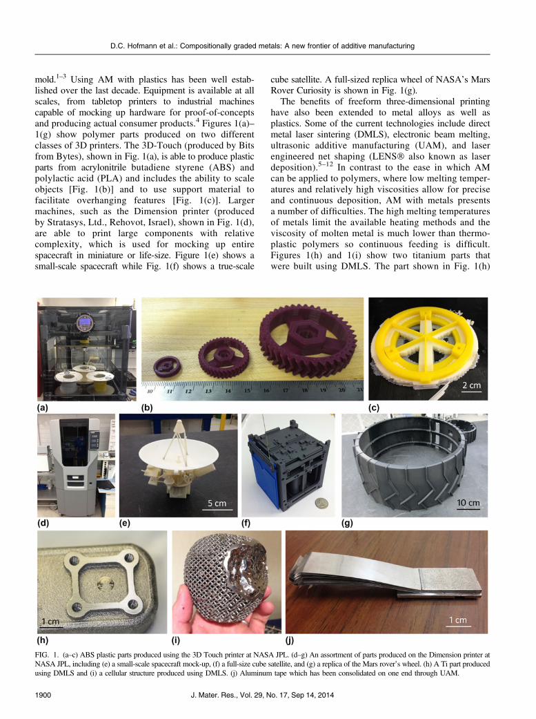
mold.1–3 Using AM with plastics has been well estab-lished over the last decade. Equipment is available at allscales, from tabletop printers to industrial machinescapable of mocking up hardware for proof-of-conceptsand producing actual consumer products.4 Figures 1(a)–1(g) show polymer parts produced on two differentclasses of 3D printers. The 3D-Touch (produced by Bitsfrom Bytes), shown in Fig. 1(a), is able to produce plasticparts from acrylonitrile butadiene styrene (ABS) andpolylactic acid (PLA) and includes the ability to scaleobjects [Fig. 1(b)] and to use support material tofacilitate overhanging features [Fig. 1(c)]. Largermachines, such as the Dimension printer (producedby Stratasys, Ltd., Rehovot, Israel), shown in Fig. 1(d),are able to print large components with relativecomplexity, which is used for mocking up entirespacecraft in miniature or life-size. Figure 1(e) shows asmall-scale spacecraft while Fig. 1(f) shows a true-scale
cube satellite. A full-sized replica wheel of NASA’s MarsRover Curiosity is shown in Fig. 1(g).
The benefits of freeform three-dimensional printinghave also been extended to metal alloys as well asplastics. Some of the current technologies include directmetal laser sintering (DMLS), electronic beam melting,ultrasonic additive manufacturing (UAM), and laserengineered net shaping (LENS� also known as laserdeposition).5–12 In contrast to the ease in which AMcan be applied to polymers, where low melting temper-atures and relatively high viscosities allow for preciseand continuous deposition, AM with metals presentsa number of difficulties. The high melting temperaturesof metals limit the available heating methods and theviscosity of molten metal is much lower than thermo-plastic polymers so continuous feeding is difficult.Figures 1(h) and 1(i) show two titanium parts thatwere built using DMLS. The part shown in Fig. 1(h)
FIG. 1. (a–c) ABS plastic parts produced using the 3D Touch printer at NASA JPL. (d–g) An assortment of parts produced on the Dimension printer atNASA JPL, including (e) a small-scale spacecraft mock-up, (f) a full-size cube satellite, and (g) a replica of the Mars rover’s wheel. (h) A Ti part producedusing DMLS and (i) a cellular structure produced using DMLS. (j) Aluminum tape which has been consolidated on one end through UAM.
D.C. Hofmann et al.: Compositionally graded metals: A new frontier of additive manufacturing
J. Mater. Res., Vol. 29, No. 17, Sep 14, 20141900

has been finished-machined in one location, demon-strating the nearly fully dense structure. Fig. 1(i) isa cellular structure which illustrates the blind featuresthat are accessible using the powder bed method ofDMLS (produced by LayerWise, Leuven, Belgium).Figure 1( j) shows aluminum metal tape that has beenconsolidated using UAM (produced by FabrisonicLLC, Columbus, OH). Among the most commerciallymature technologies for metal printing are DMLS andlaser deposition (LD), both of which use the consoli-dation of a powder using a laser heating source. DMLSuses a laser to raster over a bed of metal powder,consolidating only the powder that was subjected to thelaser heating. After each layer has been consolidated,the workbench lowers and a new layer of powder isbrushed over the workpiece and the rastering over thepowder is repeated. Once the part is completed, it isremoved from the loose powder and subsequently heat-treated using hot isostatic pressing and then can befinish-machined to remove the rough outer surfacelayer. LD works by introducing the metal powderdirectly into the laser beam as the build head rastersback and forth over a workpiece. The laser createsa liquid melt pool as it rasters, allowing for a fullydense part to be built from the substrate up, layer-by-layer. Both DMLS and LD are being widely exploredas a potential paradigm shift in the way that metal partsare fabricated. Versions of the machines now exist inindustry, at universities, and in national laboratories, allwith the aim of redefining rapid prototyping in metal.
Despite the promise of AM with metal, there are anumber of significant drawbacks to its widespread utiliz-ation alongside established manufacturing. For AM toultimately carve a space out of conventional manufacturing,there must exist a competitive case for using the technology(other than novelty). For an AM process to be selected overa conventional manufacturing technique, the drivers are
(i) The cost of the part fabricated through AM is lowerthan conventional machining.
(ii) The part is sufficiently complex that the AMprocess is faster than conventional machining or requiresfewer man-hours to fabricate.
(iii) The part cannot be conventionally machined(e.g., the part has blind machining features).
(iv) The desired part is fabricated from a metal alloywhich is difficult to machine so conventional machiningwould require longer fabrication times than AM.
(v) The resulting metal part can be standardizedreliably so that each part does not need to be subjectedto destructive quality-control testing.
(vi) The final part has a tailored composition thatcannot be formed as a billet so conventional machining isnot possible.
The three most significant drawbacks of metal AM arehigh infrastructure cost, long lead times, and lack of
standards. These limitations stifle the use of AM formass production parts or parts where precise mechanicalproperties are needed for performance. Large metal AMmachines are expensive as is the powder feedstock,build times are extremely slow, AM parts require finishmachining, and unless the final part is complex, machin-ing from a billet is faster. In some cases, however, AM isa viable technology for both production parts and proto-typing. For example, complex components (such ascellular structures or other geometries with low relativedensity) made from titanium are excellent candidates forDMLS. Titanium is hard and difficult to machine, espe-cially in a complex part where only a small percentageof the original billet remains. In these parts, DMLS cansatisfy the first five drivers listed above, and thereforehas a niche application that is more competitive than con-ventional machining. Figure 2 demonstrates such a casewhere an AM application could be applied to hardware.Optics mounts, which are metal mounts that holdmirrors, are typically complex and require precisionflexures to grasp and tilt mirrors. The mirror mountshown in Figs. 2(b) and 2(c) was fabricated out of alarge billet of Ti into the final part (image courtesy ofPaul Gardner, NASA JPL). The original dimensions ofthe billet exceeded the height of the small flexures,which demonstrates that far more than 50% of the Tiwas removed during fabrication. The schematic inFig. 2(a) shows that for a part like this, it may be costeffective to build the flexure in an additive process bydepositing only the material needed for the flexureonto the Ti substrate. Figure 2(d) shows a Ti–6Al–4V(Ti-6-4) block where a post of Ti-6-4 was depositedusing LD (produced by RPM Innovations, South Dakota).The Ti-block was then conventionally machined intothe mirror flexure, as shown in Figs. 2(e) and 2(f),using the same conventional machining that was usedto fabricate the hardware, as shown in Fig. 2(b). Thisdemonstrates that the AM process is effective when itis applied strategically, as with a part that would requiremore than 50% removal of a billet to fabricate.
III. COMPOSITIONALLY GRADED METALSUSING AM
Early in the development of LD techniques, it becameapparent that the process could be utilized to fabricatefunctionally or compositionally graded metals (i.e., gradientalloys) by mixing elemental or alloy powders as they wereintroduced into the laser.13,14 Because the LD processcreates a melt pool in the wake of the laser, the techniquecan be used to perform layer-by-layer alloying, whereeach deposited layer can have a different compositionthan the previous layer through the blending of differentfeedstock powders. This technique fundamentally changesthe paradigm for the fabrication of metal hardware because
D.C. Hofmann et al.: Compositionally graded metals: A new frontier of additive manufacturing
J. Mater. Res., Vol. 29, No. 17, Sep 14, 2014 1901

it allows, for the first time, chemical composition to beused as a design parameter. Traditionally, surface engi-neering (e.g., cladding, plating, coating, and shot peening)and localized heat treating are two ways in which themechanical or physical properties of the metal alloy can betailored in specific regions. This can be done for wear,corrosion resistance, or for hardening in a localized region,among others. In contrast, LD allows for freeform hard-ware to be fabricated from computer models so that thecomposition of the internal structure of the part can bealtered. This also allows metal parts to be fabricated thatsample large regions of compositional space, which isextremely useful for basic metallurgy and alloy develop-ment studies.
Essentially, any AM technique can be used to fabricatea gradient alloy. By definition, AM means that a part isfabricated one layer at a time in an “additive” process.Because of this, the composition of the material beingdeposited onto the previous layer can always be different,regardless of whether the feedstock is polymer, metalpowder, or metal wire.13–16 However, some AM techniquesare far more conducive to changes in feedstock composi-tion, particularly those where the feedstock is introducedinto the heating source at the build head, and not inworkpiece. Although gradient alloys have largely onlybeen demonstrated in polymers and in metals using LD,it is possible to consider other techniques as well.Electron beam freeform fabrication (EBF3), developed
at NASA Langley,17–19 works by introducing metal wireinto an electron beam. Twin arc spraying and thermalspray coating use metal wire or powder as a feedstockfor spray deposition. In both of these techniques, two ormore wires or powders could be introduced into thebuilding head (or spray gun) to fabricate gradient alloys.It is more challenging to fabricate gradient alloys usingAM techniques that require a powder bed, as with DMLS.To change composition, the powder must be drained fromthe system, modified, and then reintroduced over theworkpiece to create the gradient. In contrast, LD is anoptimal technique for creating gradient alloys becausepowder metal feedstock is sprayed into the melt poolcreated by the laser. Today’s commercial LD systemsallow for up to four different feedstock nozzles to deliverpowder to the laser, leading to a nearly infinite combina-tion of potential gradients to be formed. Figure 3(a) showsseveral compositionally graded alloys being producedusing LD at RPM Innovations. A schematic of the buildhead is shown in Fig. 3(b) with 4 powder feedersintroduced into the YAG laser. In the LD process, thelaser melts each layer, which alloys the powder and formsa metallurgical bond with the previous layer. Build timesare slow and the parts exhibit large amounts of residualheat, resulting in annealed microstructures after cooling.Depending on the desired mechanical or physical proper-ties in the final part, the gradient alloy can be designed tohave a smooth graded transition from one metal to another
FIG. 2. (a) Schematic of how two identical parts can be achieved through conventional machining (removal of material) and AM (addition ofmaterial). (b, c) A titanium mirror mount with small flexures used to hold a mirror. The part was machined from a billet. (d) A block of Ti that wasdeposited onto a Ti substrate using LD at RPM Innovations. (e, f ) The same flexure as in (b, c) machined from the part in (d), demonstrating that theadditive process requires far less machining than conventional techniques.
D.C. Hofmann et al.: Compositionally graded metals: A new frontier of additive manufacturing
J. Mater. Res., Vol. 29, No. 17, Sep 14, 20141902
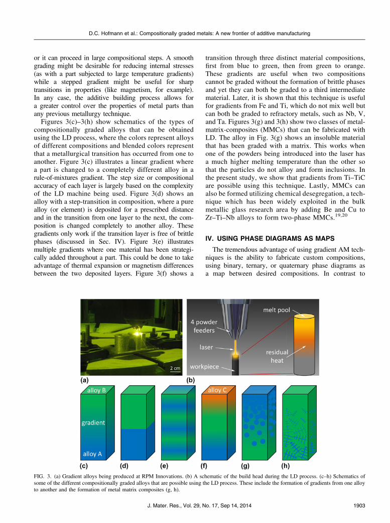
or it can proceed in large compositional steps. A smoothgrading might be desirable for reducing internal stresses(as with a part subjected to large temperature gradients)while a stepped gradient might be useful for sharptransitions in properties (like magnetism, for example).In any case, the additive building process allows fora greater control over the properties of metal parts thanany previous metallurgy technique.
Figures 3(c)–3(h) show schematics of the types ofcompositionally graded alloys that can be obtainedusing the LD process, where the colors represent alloysof different compositions and blended colors representthat a metallurgical transition has occurred from one toanother. Figure 3(c) illustrates a linear gradient wherea part is changed to a completely different alloy in arule-of-mixtures gradient. The step size or compositionalaccuracy of each layer is largely based on the complexityof the LD machine being used. Figure 3(d) shows analloy with a step-transition in composition, where a purealloy (or element) is deposited for a prescribed distanceand in the transition from one layer to the next, the com-position is changed completely to another alloy. Thesegradients only work if the transition layer is free of brittlephases (discussed in Sec. IV). Figure 3(e) illustratesmultiple gradients where one material has been strategi-cally added throughout a part. This could be done to takeadvantage of thermal expansion or magnetism differencesbetween the two deposited layers. Figure 3(f) shows a
transition through three distinct material compositions,first from blue to green, then from green to orange.These gradients are useful when two compositionscannot be graded without the formation of brittle phasesand yet they can both be graded to a third intermediatematerial. Later, it is shown that this technique is usefulfor gradients from Fe and Ti, which do not mix well butcan both be graded to refractory metals, such as Nb, V,and Ta. Figures 3(g) and 3(h) show two classes of metal-matrix-composites (MMCs) that can be fabricated withLD. The alloy in Fig. 3(g) shows an insoluble materialthat has been graded with a matrix. This works whenone of the powders being introduced into the laser hasa much higher melting temperature than the other sothat the particles do not alloy and form inclusions. Inthe present study, we show that gradients from Ti–TiCare possible using this technique. Lastly, MMCs canalso be formed utilizing chemical desegregation, a tech-nique which has been widely exploited in the bulkmetallic glass research area by adding Be and Cu toZr–Ti–Nb alloys to form two-phase MMCs.19,20
IV. USING PHASE DIAGRAMS AS MAPS
The tremendous advantage of using gradient AM tech-niques is the ability to fabricate custom compositions,using binary, ternary, or quaternary phase diagrams asa map between desired compositions. In contrast to
FIG. 3. (a) Gradient alloys being produced at RPM Innovations. (b) A schematic of the build head during the LD process. (c–h) Schematics ofsome of the different compositionally graded alloys that are possible using the LD process. These include the formation of gradients from one alloyto another and the formation of metal matrix composites (g, h).
D.C. Hofmann et al.: Compositionally graded metals: A new frontier of additive manufacturing
J. Mater. Res., Vol. 29, No. 17, Sep 14, 2014 1903

traditional alloy development, where multicomponentalloys are made one point at a time until a region of aphase diagram is understood, the gradient process allowsfor many compositions along a line to be fabricated in thesame part. This is desirable for alloy development, becausenanomechanics can be used to characterize many compo-sitions in a single sample without having to make themindividually. It is also desirable for transitioning from onealloy to another to exploit the mechanical or physicalproperties at each end of the gradient. For each gradientalloy, there must be a defined “gradient path” selected forthe AM building process. There may be many of thesepaths that could be selected depending on the functionalityrequired by part. The path could be linear, representingthe most direct route from one composition to another;the path could be curved to avoid unwanted phases; or thepath could be discontinuous to create a step in composi-tions. Examples of these types of paths are shown in aschematic ternary phase diagram in Fig. 4(a). The mostdirect route from one alloy to another is a simple mixtureof one powder to another linearly (shown with a red line).
However, if this route encounters an unwanted phase(shown schematically in the colored regions), then a pathcould be designed to circumvent that region. Withcomputer control of the gradient path, complex routesare possible. In some cases, binary transitions are desirablefor reducing complexity. In these cases, alloys with minor-ity alloy elements can be graded to a pure metal and thenblended with another pure metal. With information aboutdifferent crystal phases that form in multicomponentsystems, computer programs can be used to designgradient paths that optimize the desired function of thegraded part, whether it is a high fracture toughnesstransition from one material to another, a gradient ofmechanical or physical properties (such as melting tem-perature, thermal expansion, or magnetism, for example),or stepped transitions from one alloy to another to avoidunwanted phases.
Developing gradient paths for compositionallygraded alloys is greatly assisted through the use ofpredictive phase diagram modeling. In the currentresearch, the authors developed predictive gradient paths
FIG. 4. (a) A schematic of a ternary phase diagram showing possible gradient paths from one alloy to another across a three-element phase space.Several routes are possible, based on factors such as the avoidance of brittle phases. (b, c) Gradient alloys which cracked during fabrication.(b) A failed gradient from Ti to Invar and (c) a failed gradient from Ti to 304L stainless steel. (d) A calculated Al–Ti–V phase diagram showinga gradient from Ti–6Al–4V to pure V showing three different gradient paths: (1) a linear gradient, (2) removing Al and then performing a binaryTi–V gradient, (3) an arbitrary path. The blue region is calculated to be free of brittle intermetallic phases and is comprised of hcp and bcc phases.(e) A calculated phase diagram for the Fe–Ni–Cr system showing a gradient from 304L stainless steel to Invar 36. In this diagram, the blue regionhas been calculated to be all single phase austenite, which simplifies the build due to the absence of brittle phases.
D.C. Hofmann et al.: Compositionally graded metals: A new frontier of additive manufacturing
J. Mater. Res., Vol. 29, No. 17, Sep 14, 20141904

for the LD process using the CALPHAD method.21–24
Using information about the desired composition and pro-cessing conditions of the samples, phase diagrams can becalculated which predict the phases that will be present inthe solidified gradient alloy. Figure 4(d) shows such aphase diagram for the Ti–Al–V system, where threedifferent gradient paths are shown for the transition fromTi-6-4 to pure elemental V. Although details about thisgradient will be published elsewhere, the three pathsindicate the different ways that Ti-6-4 can be transitionedto V without encountering brittle intermetallic phases.These include the linear route (which was developedexperimentally and is labeled 1), the route where Ti-6-4is transitioned to pure Ti and then pure V (labeled route 2),and the arbitrary path (labeled route 3). A similar gradientfrom Ti-6-4 to pure Nb (another refractory metal) is dis-cussed later, as shown in Fig. 7. Figure 4(d) shows acalculated phase diagram for the transition from 304Lstainless steel (;Fe68Cr20Ni10Mn,1Si,1 in wt%) to Invar36 (Fe64Ni36 in wt%). The calculated phase diagramaccurately predicts the single phase austenite at all com-positions of the gradient, which was verified experimen-tally. In many alloy systems, however, obvious transitionsbetween alloys of interest do not exist. For example,Fig. 4(d) shows that a transition from Ti-6-4 to pure V isfree of brittle phases; however, a transition from Ti-6-4to pure Al would form many brittle phases. To test theeffect of these transitions, several gradients were deliber-ately steered toward locations in composition space wherebrittle compositions were expected. Figures 4(b) and 4(c)show failed gradients in a transition from Ti to Invar 36and another one from Ti to 304L steel. As expected, thethermal stresses associated with the AM building processcause cracking in the brittle ordered phases that form.In some cases, the gradient alloy breaks off and the depo-sition is halted, while in other cases a crack is visible at alocation along the gradient. Cross-sectional scanningelectron microscopy (SEM) image on these alloys verifiesthat brittle phases have formed and cracked (see Fig. 7 formore detail).
V. A ROADMAP FOR CREATINGGRADIENT ALLOYS
Compositionally graded metals offer both the oppor-tunity to explore basic science research as well as todesign hardware with properties that cannot be attainedusing traditional manufacturing. Designing a gradientalloy for a particular application starts by identifying amultifunctional part that requires the gradient. Theneed may arise from an application with problematicmechanical property issues (e.g., a thermal expansionmismatch), a metal part that needs to be joined to adissimilar metal part (e.g., a titanium to steel weld), ora desire to make the design and function of a part more
elegant (e.g., a single-piece component with multifunc-tional mechanical properties). Figure 5 shows a finiteelement model of a typical part that might benefit froma gradient alloy; an automobile valve stem. The modelshows that at 1000 K the joint with the gradient alloyhas an approximately ten times lower stress due to thelack of thermal expansion. The gradient joint has anorder of magnitude lower stress at 1000 K due to thermalexpansion.
The next step in gradient design is to identify the alloysthat, when combined, could achieve the desired propertiesrequired by the application. For example, if one side ofa metal part is exposed to high temperatures and the otherside needs to be low density, several gradient choices arepossible. The high temperature side could be a refractorymetal, such as Ta, Nb, V, Mo, or W while the low densitymetal could be Al or Ti. Once some potential alloysare selected, the gradient needs to be designed in such away as to satisfy the desired properties of the final part.Advanced computer modeling can be used to optimizethe design of a part to exploit differences in mechanicalproperties between alloys. Once the part is modeled,a gradient path must be developed to transition betweenthe alloys of interest without creating brittle or unwantedphases. If this is demonstrated successfully, then an AMbuilding technique must be selected to fabricate the part.Although LD was used in the current work, this may notbe the best solution for all desired gradients. For example,some metal alloys may be difficult to obtain in powderform but are readily available in wire. If the gradient alloy
FIG. 5. A finite element model showing elastic mismatch in twodissimilar metal automobile valve stems at 1000 K. The figure on theleft shows a valve with a 304L stainless steel stem connected to anInconel 625 valve via a 2.5 cm long gradient of composition. On theright, the gradient is replaced with a friction weld. The stress at thejoint of the friction welded part has an approximately ten times higherstress than the compositionally graded alloy.
D.C. Hofmann et al.: Compositionally graded metals: A new frontier of additive manufacturing
J. Mater. Res., Vol. 29, No. 17, Sep 14, 2014 1905
has a small thickness, but a large surface area, then spraycoating the gradient might be a viable option. Spraycoating can be used to fabricate gradient alloysby changing the composition of the powder or wire thatenters the spray nozzle.
VI. COMPOSITIONALLY GRADED METALS AS ANEW BASIC SCIENCE RESEARCH AREA
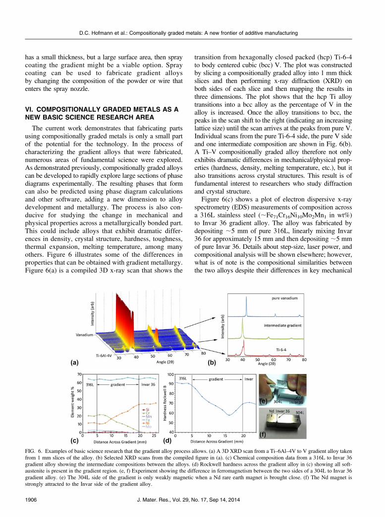
The current work demonstrates that fabricating partsusing compositionally graded metals is only a small partof the potential for the technology. In the process ofcharacterizing the gradient alloys that were fabricated,numerous areas of fundamental science were explored.As demonstrated previously, compositionally graded alloyscan be developed to rapidly explore large sections of phasediagrams experimentally. The resulting phases that formcan also be predicted using phase diagram calculationsand other software, adding a new dimension to alloydevelopment and metallurgy. The process is also con-ducive for studying the change in mechanical andphysical properties across a metallurgically bonded part.This could include alloys that exhibit dramatic differ-ences in density, crystal structure, hardness, toughness,thermal expansion, melting temperature, among manyothers. Figure 6 illustrates some of the differences inproperties that can be obtained with gradient metallurgy.Figure 6(a) is a compiled 3D x-ray scan that shows the
transition from hexagonally closed packed (hcp) Ti-6-4to body centered cubic (bcc) V. The plot was constructedby slicing a compositionally graded alloy into 1 mm thickslices and then performing x-ray diffraction (XRD) onboth sides of each slice and then mapping the results inthree dimensions. The plot shows that the hcp Ti alloytransitions into a bcc alloy as the percentage of V in thealloy is increased. Once the alloy transitions to bcc, thepeaks in the scan shift to the right (indicating an increasinglattice size) until the scan arrives at the peaks from pure V.Individual scans from the pure Ti-6-4 side, the pure V sideand one intermediate composition are shown in Fig. 6(b).A Ti–V compositionally graded alloy therefore not onlyexhibits dramatic differences in mechanical/physical prop-erties (hardness, density, melting temperature, etc.), but italso transitions across crystal structures. This result is offundamental interest to researchers who study diffractionand crystal structure.
Figure 6(c) shows a plot of electron dispersive x-rayspectrometry (EDS) measurements of composition acrossa 316L stainless steel (;Fe71Cr16Ni10Mo2Mn1 in wt%)to Invar 36 gradient alloy. The alloy was fabricated bydepositing ;5 mm of pure 316L, linearly mixing Invar36 for approximately 15 mm and then depositing ;5 mmof pure Invar 36. Details about step-size, laser power, andcompositional analysis will be shown elsewhere; however,what is of note is the compositional similarities betweenthe two alloys despite their differences in key mechanical
FIG. 6. Examples of basic science research that the gradient alloy process allows. (a) A 3D XRD scan from a Ti–6Al–4V to V gradient alloy takenfrom 1 mm slices of the alloy. (b) Selected XRD scans from the compiled figure in (a). (c) Chemical composition data from a 316L to Invar 36gradient alloy showing the intermediate compositions between the alloys. (d) Rockwell hardness across the gradient alloy in (c) showing all soft-austenite is present in the gradient region. (e, f) Experiment showing the difference in ferromagnetism between the two sides of a 304L to Invar 36gradient alloy. (e) The 304L side of the gradient is only weakly magnetic when a Nd rare earth magnet is brought close. (f) The Nd magnet isstrongly attracted to the Invar side of the gradient alloy.
D.C. Hofmann et al.: Compositionally graded metals: A new frontier of additive manufacturing
J. Mater. Res., Vol. 29, No. 17, Sep 14, 20141906
properties, such as thermal expansion, magnetism, andhardness. Both alloys have similar percentages of Fe, butInvar 36 has an increased percentage of Ni and no Cr,while 316L has both Ni and Cr. At each intermediatecomposition in the alloy, a single phase of soft austenitewas formed, as verified by hardness measurements[Fig. 6(d)], XRD analysis, and phase diagram calculations[Fig. 4(e)]. Despite the subtle changes in compositionbetween the two ends of the gradient alloy, severalkey mechanical properties were graded significantly.Figures 6(e) and 6(f) show experimentally the differencesin ferromagnetism between the two sides of the gradient.A powerful rare-earth magnet does not attract the 316Lside of the gradient but does attract the Invar 36 side.Similarly, the coefficient of thermal expansion (CTE)in both sides of the gradient is significantly different,considering Invar 36 has a nearly zero CTE at lowtemperatures. These measurements will also be includedin another study.
Figure 6 demonstrates that compositionally gradedalloys allow for a broad range of basic science studies,largely based on the fact that these alloys cannot be fab-ricated utilizing other processing techniques. Among these,information about crystal structures, intermediate alloycompositions, physical properties, and mechanical proper-ties are the most interesting because these features of analloy cannot be changed easily using mature metallurgytechniques. Gradient alloys change the paradigm for howproperties can be distributed in a material, making them offundamental interest.
VII. HARDWARE WHICH EXPLOITS GRADIENTCOMPOSITIONS
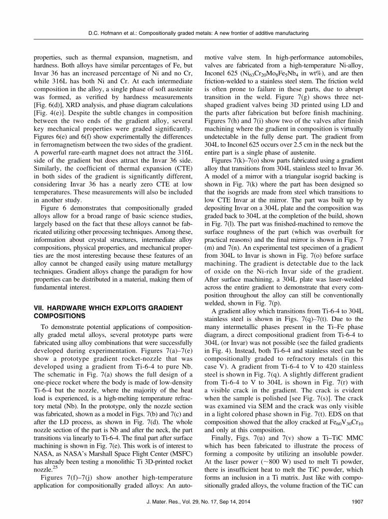
To demonstrate potential applications of composition-ally graded metal alloys, several prototype parts werefabricated using alloy combinations that were successfullydeveloped during experimentation. Figures 7(a)–7(e)show a prototype gradient rocket-nozzle that wasdeveloped using a gradient from Ti-6-4 to pure Nb.The schematic in Fig. 7(a) shows the full design of aone-piece rocket where the body is made of low-densityTi-6-4 but the nozzle, where the majority of the heatload is experienced, is a high-melting temperature refrac-tory metal (Nb). In the prototype, only the nozzle sectionwas fabricated, shown as a model in Figs. 7(b) and 7(c) andafter the LD process, as shown in Fig. 7(d). The wholenozzle section of the part is Nb and after the neck, the parttransitions via linearly to Ti-6-4. The final part after surfacemachining is shown in Fig. 7(e). This work is of interest toNASA, as NASA’s Marshall Space Flight Center (MSFC)has already been testing a monolithic Ti 3D-printed rocketnozzle.25
Figures 7(f)–7(j) show another high-temperatureapplication for compositionally graded alloys: An auto-
motive valve stem. In high-performance automobiles,valves are fabricated from a high-temperature Ni-alloy,Inconel 625 (Ni63Cr20Mo8Fe5Nb4 in wt%), and are thenfriction-welded to a stainless steel stem. The friction weldis often prone to failure in these parts, due to abrupttransition in the weld. Figure 7(g) shows three net-shaped gradient valves being 3D printed using LD andthe parts after fabrication but before finish machining.Figures 7(h) and 7(i) show two of the valves after finishmachining where the gradient in composition is virtuallyundetectable in the fully dense part. The gradient from304L to Inconel 625 occurs over 2.5 cm in the neck but theentire part is a single phase of austenite.
Figures 7(k)–7(o) show parts fabricated using a gradientalloy that transitions from 304L stainless steel to Invar 36.A model of a mirror with a triangular isogrid backing isshown in Fig. 7(k) where the part has been designed sothat the isogrids are made from steel which transitions tolow CTE Invar at the mirror. The part was built up bydepositing Invar on a 304L plate and the composition wasgraded back to 304L at the completion of the build, shownin Fig. 7(l). The part was finished-machined to remove thesurface roughness of the part (which was overbuilt forpractical reasons) and the final mirror is shown in Figs. 7(m) and 7(n). An experimental test specimen of a gradientfrom 304L to Invar is shown in Fig. 7(o) before surfacemachining. The gradient is detectable due to the lackof oxide on the Ni-rich Invar side of the gradient.After surface machining, a 304L plate was laser-weldedacross the entire gradient to demonstrate that every com-position throughout the alloy can still be conventionallywelded, shown in Fig. 7(p).
A gradient alloy which transitions from Ti-6-4 to 304Lstainless steel is shown in Figs. 7(q)–7(t). Due to themany intermetallic phases present in the Ti–Fe phasediagram, a direct compositional gradient from Ti-6-4 to304L (or Invar) was not possible (see the failed gradientsin Fig. 4). Instead, both Ti-6-4 and stainless steel can becompositionally graded to refractory metals (in thiscase V). A gradient from Ti-6-4 to V to 420 stainlesssteel is shown in Fig. 7(q). A slightly different gradientfrom Ti-6-4 to V to 304L is shown in Fig. 7(r) witha visible crack in the gradient. The crack is evidentwhen the sample is polished [see Fig. 7(s)]. The crackwas examined via SEM and the crack was only visiblein a light colored phase shown in Fig. 7(t). EDS on thatcomposition showed that the alloy cracked at Fe60V30Cr10and only at this composition.
Finally, Figs. 7(u) and 7(v) show a Ti–TiC MMCwhich has been fabricated to illustrate the process offorming a composite by utilizing an insoluble powder.At the laser power (;800 W) used to melt Ti powder,there is insufficient heat to melt the TiC powder, whichforms an inclusion in a Ti matrix. Just like with compo-sitionally graded alloys, the volume fraction of the TiC can
D.C. Hofmann et al.: Compositionally graded metals: A new frontier of additive manufacturing
J. Mater. Res., Vol. 29, No. 17, Sep 14, 2014 1907

be increased to change the volume fraction of the inclusion.Several Ti–TiC gradient alloys were produced wherethe volume fraction of TiC was increased until crackingoccurred. The gradient alloys shown in Figs. 7(u) and 7(v)
are pure Ti on one side and are 50% by volume TiC on theother, which was the largest attainable volume fraction.Optical micrographs from the alloy are shown in Fig. 7(v)to demonstrate the gradient visually.
FIG. 7. Prototypes of gradient alloys fabricated using LD. (a–e) A Ti-6-4 to Nb rocket nozzle where the nozzle if fabricated from a high-temperaturerefractory metal, Nb, and the body of the rocket is fabricated from low-density Ti-6-4. (f–j) The fabrication of 304L to Inconel 626 valve stems where thevalve is high-temperature Inconel 625 and the stem is 304L stainless steel. This part is typically made using a friction weld. (k–n) A 304L to Invar 36gradient mirror with isogrid backing for increased stiffness. (o) A 304L to Invar 36 gradient alloy without any surface machining, showing the differencein oxide between the two alloys. (p) The alloy from (o) after surface machining and laser welding of a 304L plate, demonstrating weldability of thegradient alloy. (q) A successful gradient from Ti-6-4 to V, then from V to 420 stainless steel. (r) A similar gradient alloy to (q) but with a transition fromTi-6-4 to V, then from V to 304L, showing a crack. (s) After polishing, the crack at a specific composition is visible. (t) SEM micrograph showing thata brittle Fe–V–Cr phase has resulted in the cracking of the gradient alloy. (u) At Ti-6-4 to TiC gradient alloy. (v) Tiled micrographs from the gradient in(u) where the black phase is the TiC particles. This demonstrates the formation of a metal matrix composite using LD.
D.C. Hofmann et al.: Compositionally graded metals: A new frontier of additive manufacturing
J. Mater. Res., Vol. 29, No. 17, Sep 14, 20141908
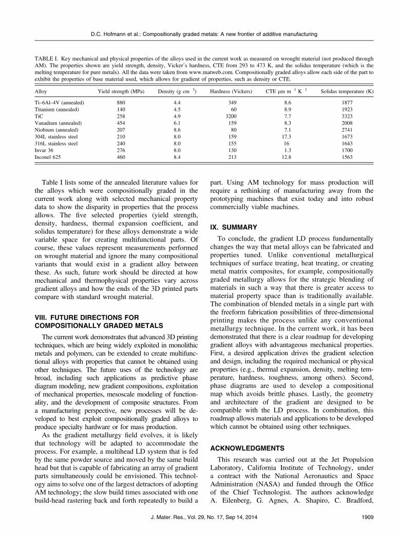
Table I lists some of the annealed literature values forthe alloys which were compositionally graded in thecurrent work along with selected mechanical propertydata to show the disparity in properties that the processallows. The five selected properties (yield strength,density, hardness, thermal expansion coefficient, andsolidus temperature) for these alloys demonstrate a widevariable space for creating multifunctional parts. Ofcourse, these values represent measurements performedon wrought material and ignore the many compositionalvariants that would exist in a gradient alloy betweenthese. As such, future work should be directed at howmechanical and thermophysical properties vary acrossgradient alloys and how the ends of the 3D printed partscompare with standard wrought material.
VIII. FUTURE DIRECTIONS FORCOMPOSITIONALLY GRADED METALS
The current work demonstrates that advanced 3D printingtechniques, which are being widely exploited in monolithicmetals and polymers, can be extended to create multifunc-tional alloys with properties that cannot be obtained usingother techniques. The future uses of the technology arebroad, including such applications as predictive phasediagram modeling, new gradient compositions, exploitationof mechanical properties, mesoscale modeling of function-ality, and the development of composite structures. Froma manufacturing perspective, new processes will be de-veloped to best exploit compositionally graded alloys toproduce specialty hardware or for mass production.
As the gradient metallurgy field evolves, it is likelythat technology will be adapted to accommodate theprocess. For example, a multihead LD system that is fedby the same powder source and moved by the same buildhead but that is capable of fabricating an array of gradientparts simultaneously could be envisioned. This technol-ogy aims to solve one of the largest detractors of adoptingAM technology; the slow build times associated with onebuild-head rastering back and forth repeatedly to build a
part. Using AM technology for mass production willrequire a rethinking of manufacturing away from theprototyping machines that exist today and into robustcommercially viable machines.
IX. SUMMARY
To conclude, the gradient LD process fundamentallychanges the way that metal alloys can be fabricated andproperties tuned. Unlike conventional metallurgicaltechniques of surface treating, heat treating, or creatingmetal matrix composites, for example, compositionallygraded metallurgy allows for the strategic blending ofmaterials in such a way that there is greater access tomaterial property space than is traditionally available.The combination of blended metals in a single part withthe freeform fabrication possibilities of three-dimensionalprinting makes the process unlike any conventionalmetallurgy technique. In the current work, it has beendemonstrated that there is a clear roadmap for developinggradient alloys with advantageous mechanical properties.First, a desired application drives the gradient selectionand design, including the required mechanical or physicalproperties (e.g., thermal expansion, density, melting tem-perature, hardness, toughness, among others). Second,phase diagrams are used to develop a compositionalmap which avoids brittle phases. Lastly, the geometryand architecture of the gradient are designed to becompatible with the LD process. In combination, thisroadmap allows materials and applications to be developedwhich cannot be obtained using other techniques.
ACKNOWLEDGMENTS
This research was carried out at the Jet PropulsionLaboratory, California Institute of Technology, undera contract with the National Aeronautics and SpaceAdministration (NASA) and funded through the Officeof the Chief Technologist. The authors acknowledgeA. Eilenberg, G. Agnes, A. Shapiro, C. Bradford,
TABLE I. Key mechanical and physical properties of the alloys used in the current work as measured on wrought material (not produced throughAM). The properties shown are yield strength, density, Vicker’s hardness, CTE from 293 to 473 K, and the solidus temperature (which is themelting temperature for pure metals). All the data were taken from www.matweb.com. Compositionally graded alloys allow each side of the part toexhibit the properties of base material used, which allows for gradient of properties, such as density or CTE.
Alloy Yield strength (MPa) Density (g cm�3) Hardness (Vickers) CTE lm m�1 K�1 Solidus temperature (K)
Ti–6Al–4V (annealed) 880 4.4 349 8.6 1877Titanium (annealed) 140 4.5 60 8.9 1923TiC 258 4.9 3200 7.7 3323Vanadium (annealed) 454 6.1 159 8.3 2008Niobium (annealed) 207 8.6 80 7.1 2741304L stainless steel 210 8.0 159 17.3 1673316L stainless steel 240 8.0 155 16 1643Invar 36 276 8.0 130 1.3 1700Inconel 625 460 8.4 213 12.8 1563
D.C. Hofmann et al.: Compositionally graded metals: A new frontier of additive manufacturing
J. Mater. Res., Vol. 29, No. 17, Sep 14, 2014 1909

P. Gardner, C. Morandi, J. Mulder, P. Willis, and RPMInnovations for useful discussions. Richard Otis andZi-Kui Liu acknowledge partial funding of this workby the Open Manufacturing Program of the DefenseAdvanced Research Projects Agency’s Center forInnovative Materials Processing through Direct DigitalDeposition at Penn State under Grant N00014-12-1-0840from the Office of Naval Research.
REFERENCES
1. N. Hopkinson, R. Hague, and P. Dickens: Rapid Manufacturing:An Industrial Revolution for a Digital Age (Wiley-Blackwell,Berlin, Germany, 2005).
2. R.I. Campbell, R.J.M. Hague, B. Sener, and P.W. Wormald: Thepotential for the bespoke industrial designer. Des. J. 6, 24–34(2003).
3. R.J.M. Hague, R.I. Campbell, and P.M. Dickens: Implications ondesign of rapid manufacturing. Proc. Inst. Mech. Eng., Part C 217,25–30 (2003).
4. I. Gibson, D.W. Rosen, and B. Stucker: Additive ManufacturingTechnologies: Rapid Prototyping to Direct Digital Manufacturing(Springer, New York, 2010).
5. E.C. Santos, M. Shiomi, K. Osakada, and T. Laoui: Rapidmanufacturing of metal components by laser forming. Int.J. Mach. Tools Manuf. 46, 1459–1468 (2006).
6. M.L. Griffith, M.T. Ensz, J.D. Puskar, C.V. Robino, J.A. Brooks,J.A. Philliber, J.E. Smugeresky, and W.H. Hofmeister:Understanding the microstructure and properties of componentsfabricated by laser engineered net shaping (LENS). MRS Proc.625, 9 (2011).
7. A. Crespo and R. Vilar: Finite element analysis of the rapidmanufacturing of Ti–6Al–4V parts by laser powder deposition.Scr. Mater. 63, 140–143 (2010).
8. S. Kelly and S. Kampe: Microstructural evolution in laser-depositedmultilayer Ti-6Al-4V builds: Part I. Microstructural characterization.Metall. Mater. Trans. 35, 1861–1867 (2004).
9. L.E. Murr, S.A. Quinones, S.M. Gaytan, M.I. Lopez, A. Rodela,E.Y. Martinez, D.H. Hernandez, E. Martinez, F. Medina, andR.B. Wicker: Microstructure and mechanical behavior of Ti-6Al-4Vproduced by rapid-layer manufacturing, for biomedical applications.J. Mech. Behav. Biomed. Mater. 2, 20–32 (2009).
10. H. Tan, F. Zhang, J. Chen, X. Lin, and W. Huang: Microstructureevolution of laser solid forming of Ti-Al-V ternary systemalloys from blended elemental powders. Chin. Opt. Lett. 9,051403–051406 (2011).
11. K.I. Schwendner, R. Banerjee, P.C. Collins, C.A. Brice, andH.L. Fraser: Direct laser deposition of alloys from elementalpowder blends. Scr. Mater. 45, 1123–1129 (2001).
12. L. Xue and M.U. Islam: Free-form laser consolidation for producingmetallurgically sound and functional components. J. Laser Appl.12, 160 (2000).
13. R. Banerjee, P.C. Collins, D. Bhattacharyya, S. Banerjee, andH.L. Fraser: Microstructural evolution in laser deposited compo-sitionally graded a/b titanium-vanadium alloys. Acta Mater. 51,3277–3292 (2003).
14. P.C. Collins, R. Banerjee, S. Banerjee, and H.L. Fraser: Laserdeposition of compositionally graded titanium–vanadium andtitanium–molybdenum alloys. Mater. Sci. Eng., A 352, 118–128(2003).
15. M.B. Bever and P.F. Duwez: Gradients in composite materials.Mater. Sci. Eng. 10, 1–8 (1972).
16. M. Shen and M.B. Bever: Gradients in polymeric materials.J. Mater. Sci. 7, 741–746 (1972).
17. K.M.B. Taminger and R.A. Hafley: Electron beam freeformfabrication: A rapid metal deposition process. In Proc. of the3rd Ann. Auto. Comp. Conf., 2003; pp. 1–6.
18. J.K. Watson, K.M.B. Taminger, R.A. Hafley, and D.D. Petersen:Development of a prototype electron beam freeform fabricationsystem. In Proc. of 13th SFF Symp., 2002; pp. 458–465.
19. C.A. Brice and D.S. Henn: Rapid prototyping and freeformfabrication via electron beam welding deposition. Proceedingof International Institute of Welding Conference, Copenhagen,Denmark (2002).
20. D.C. Hofmann, J-Y. Suh, A. Wiest, G. Duan, M-L. Lind,M.D. Demetriou, and W.L. Johnson: Designing metallic glassmatrix composites with high toughness and tensile ductility.Nature, 451 (2008), 1085–1089.
21. D.C. Hofmann, J-Y. Suh, A. Wiest, M-L. Lind, M.D. Demetriou,and W.L. Johnson: Development of tough, low-density titanium-based bulk metallic glass matrix composites with tensile ductility.Proc. Natl. Acad. Sci. U. S. A. 105, 20136–20140 (2008).
22. Z-K. Liu: First-principles calculations, and CALPHAD modelingof thermodynamics. J. Phase Equilib. Diffus. 30, 517–534 (2009).
23. J-O. Andersson, T. Helander, L. Höglund, P. Shi, andB. Sundman: Thermo-Calc & DICTRA, computational tools formaterials science. CALPHAD 26, 273–312 (2002).
24. L. Kaufman and H. Bernstein: Computer Calculation of PhaseDiagrams with Special Reference to Refractory Metal (AcademicPress, New York, NY, 1970).
25. See for example, http://www.nasa.gov/exploration/systems/sls/3d-printed-rocket-injector.html#.U5IRMU1OVaQ, NASA TestLimits of 3-D Printing with Powerful Rocket Engine Check,2013.
D.C. Hofmann et al.: Compositionally graded metals: A new frontier of additive manufacturing
J. Mater. Res., Vol. 29, No. 17, Sep 14, 20141910