Embed Size (px)
Citation preview
ARTICLE
Three-dimensional study of twin boundaries in conventional andgrain boundary-engineered 316L stainless steels
Tingguang LiuSchool of Materials Science and Engineering, Shanghai University, Shanghai 200072, China; and National Centerfor Materials Service Safety, University of Science and Technology Beijing, Beijing 100083, China
Shuang Xiaa)School of Materials Science and Engineering, State Key Laboratory of Advanced Special Steel, ShanghaiUniversity, Shanghai 200072, China; and Shanghai Xinmin (Dongtai) Duty Forging Co., Ltd., Dongtai 224200,China
Bangxin Zhou and Qin BaiSchool of Materials Science and Engineering, Shanghai University, Shanghai 200072, China
Gregory S. RohrerDepartment of Materials Science and Engineering, Carnegie Mellon University, Pittsburgh, Pennsylvania 15213,USA
(Received 13 February 2018; accepted 18 April 2018)
The three-dimensional microstructures of two conventional 316L stainless steels and a grainboundary (GB)-engineered version of the same steel have been characterized by using serialsectioning and electron backscatter diffraction mapping. The morphologies, area fractions, andnumber fractions of twin boundaries (TBs) were measured and compared, and the randomboundary connectivity was evaluated. Although two-dimensional observations suggest that TBsare planar, occluded twin-grains and tunnel-shaped TBs were also observed. In addition, somelarge and morphologically complex TBs were observed in the GB-engineered sample, and theseTBs were responsible for the increase in the twin area fraction that has been reported in paststudies. While GB engineering increased the boundary area fraction, the TB number fraction wasalmost unchanged. Because the GB engineering process changed only the area fraction and notthe number fraction, the connectivity of random boundaries was not disrupted.
I. INTRODUCTION
Annealing twin boundaries (TBs) are common in face-centered cubic materials with medium and low stackingfault energies,1,2 such as 316L stainless steel. TBs havean extraordinary morphology that is generally a straightline in a two-dimensional (2D) observation, arousinga strong research interest since early in the last century.1
Compared with random boundaries, TBs have not onlya conspicuous morphology but also special properties,such as lower boundary energy and increased resistanceto impurity segregation, precipitation of minority phases,3
and intergranular degradation.4–11 The concept of “grainboundary design and control,” proposed by Watanabe,12
aimed to improve grain boundary (GB)-related propertiesof materials via increasing the proportion of so-calledspecial boundaries such as TBs. This research field isnow well known as “grain boundary engineering”,5,13–27
which has been successfully applied in many materials,
such as stainless steels,5,7,21 Ni-based alloys,13,14 andCu-based alloys16 through thermomechanical processing.The misorientation component of the GB character is
generally described using the coincidence site lattice(CSL) model. In the CSL model, the
P-value is the
reciprocal density of coincident lattice sites of the twograins adjacent to the boundary, and boundaries withlow-
Pvalues (
P-value # 29) are generally considered
special. The proportion of low-P
CSL boundaries can beincreased from 40% to more than 75% by GB engineer-ing.5,13–22 Of the new special boundaries, about 80% areTBs, which are designated as
P3 in the CSL model.
However, until recently, all the related results werederived from microstructure data in 2D maps. The low-P
CSL boundary proportions were calculated using thelength or the number of boundaries observed on 2Dsectional maps rather than the actual boundary area ortotal number of boundaries in 3D microstructures.Besides the GB character distribution, other micro-
structural characteristics should be considered to evaluatethe effectiveness of GB engineering, such as the size oftwin-related domains and GB connectivity. A twin-related domain13,14,19,23–27 is a crystallographically con-strained domain in which all grains can be connected via
a)Address all correspondence to this author.e-mail: [email protected], [email protected]
DOI: 10.1557/jmr.2018.133
J. Mater. Res., 2018 !Materials Research Society 2018 16 CCC 1/:0 7253 5 1 3 3 : 6 2 7 5 8: , C /232 : 6 CCC 1/:0 7253 5 1 3 / 3573 3 . 7 3 7 D /D / 0831 63 /:0 7253 3 3 : 3 / /7 /0 3 /
onlyP
3n boundaries. A recent study has compared thetwin-related microstructures in a conventional and a GB-engineered copper in 3D, finding that twin-relateddomains are much larger in the GB-engineered copper.26
The improvement of the resistance to intergranulardegradation by GB engineering is substantially relatedto the random boundary connectivity.5,17,28–31 However,until recently, 3D studies of GB networks were rare,except for computer simulation. Simulations showed thatwhile the fraction of special boundaries that is required tobreak up a 2D network of random boundaries is 0.35,special boundary fractions of 0.775–0.85 are required todisrupt the connectivity of random boundaries in 3D.32 Alatest paper from our group33 investigated the character-istics of the 3D GB network of 316L stainless steel beforeand after GB engineering. The same raw data were usedin the current paper, but the current study focuses on the3D TBs. The twin-related domains in the GB-engineered316L are larger and have more complex topologicalstructures than that in the conventional 316L.33 However,the TB fraction in triple junctions and quadruple junc-tions only has a slight increase after GB engineering.
Our current understanding of TBs is based mostly onobservations from 2D sections. Based on 2D observa-tions, the morphologies of twins have been classified intofour categories: grain-corner twins, complete parallel-sided twins that span a grain, incomplete parallel-sidedtwins that do not span the grain, and island twins.2,34 Anearly 3D study by Bystrzycki35 showed that there wereonly two types of twins: lamellar twins and corner twins.However, because of the low resolution of the 3Dmicrostructure in Ref. 35, it is uncertain whether othertypes of twins exist or not. In addition, because somemorphologically complex TBs can be observed in 2D-EBSD (electron backscatter diffraction) maps of GB-engineered materials,13–15,17,18,36 the actual morphologiesof these boundaries are unclear. Further 3D characteriza-tion of GB-engineered microstructures is necessary toquantify the differences between conventional and GB-engineered materials.
The 3D microstructure of a 316L stainless steel wasmeasured before and after GB engineering by 3D-EBSDto determine the changes brought about by GB engineer-ing. Although most 3D-EBSD data have been collectedusing focused ion beam (FIB) serial sectioning combinedwith EBSD mapping,37–39 the field of view that can besectioned by FIB is rated small, usually less than 100 lm.This means that in alloys with grain sizes in the range of30–40 lm, very few grains are contained in the field ofview. Therefore, in the current work, 3D-EBSD data havebeen collected by coupling EBSD mapping with serialsectioning by mechanical polishing.40–43 This makes itpossible to map fields of view as large as 800 lm,containing hundreds of grains in microstructures with anaverage grain diameter in the range of 30–40 lm.
A paper, focused on the 3D characteristics of the GBnetwork before and after GB engineering using the 3D-EBSD data, had been published elsewhere.33 In the currentpaper, the morphology, area fraction, number fraction, andconnectivity of TBs in 3D before and after GB engineeringhave been measured. The results show some character-istics of GB-engineered microstructures that cannot beobserved in 2D maps and reveal that the key point withrespect to GB engineering process is the increased TBnumber fraction rather than area/length fraction to disruptthe connectivity of random boundary network.
II. EXPERIMENTAL
A commercially available hot-forged 316L stainless steelwith a thickness of 40 mm, which has a chemical compo-sition (wt%) of Cr 16.26, Ni 10.10, Mo 2.08, C 0.028, Si0.47, Mn 1.03, P 0.044, S 0.005, and Fe in balance, wasused in this work. A block with a size of 40 ! 50 !134 mm3 was machined using a wire-cut electrical dis-charge machine from the as-received 316L plate. Sub-sequently, it was hot-rolled to a 50% reduction in thicknessat 1000 °C followed immediately by water quenching. Thesample was then cut into three pieces. One piece (316LL)was annealed at 1050 °C for 150 min and water quenched.The second piece (316LS) was annealed at 1000 °C for30 min and water quenched. These processes createduniformly recrystallized microstructures with different grainsizes. The third piece (316LGBE) of the material wasthermomechanically processed to increase the fraction oflow-
PCSL boundaries, and the process referred to as GB
engineering. It was first annealed at 1000 °C for 30 min andwater quenched. Next, it was warm-rolled with one pass toa 5% thickness reduction at a starting temperature of 400 °Cand then water quenched. Finally, it was annealed at1100 °C for 60 min and water quenched for fullrecrystallization.
The three samples were investigated by 3D orientationimaging microscopy. Mechanical polishing was used tocreate a series of parallel 2D sections. A CamScanApollo 300 field emission scanning electron microscope(CamScan, Cambridge, United Kingdom) equipped withan Oxford/HKL EBSD system (Oxford Instruments,Oxford, United Kingdom) was used to measure crystalorientation data on the cross section after each polishingstep. The workflow for the 3D-EBSD data acquisitioncould be described as follows: mechanical polishing !thickness reduction measurement ! marking the regionsof interest by using microhardness indents ! EBSDmapping. Highly precise serial sectioning is a key stepduring the 3D-EBSD collection, but the norm of pre-cision is related to the grain size of the measured material.A section thickness less than one 10th of the averagegrain diameter is an appropriate precision. 2D EBSDmaps of the three samples, 316LL, 316LS, and
T. Liu et al.: Three-dimensional study of twin boundaries in conventional and grain boundary-engineered 316L stainless steels
J. Mater. Res., 201826 CCC 1/:0 7253 5 1 3 3 : 6 2 7 5 8: , C /232 : 6 CCC 1/:0 7253 5 1 3 / 3573 3 . 7 3 7 D /D / 0831 63 /:0 7253 3 3 : 3 / /7 /0 3 /
316LGBE, showed that their average grain diameters are50 lm, 33 lm, and 47 lm, respectively. Therefore,during 3D-EBSD data acquisition, the target values forthickness reduction in each polishing cycle were set as2.5 lm, 2.5 lm, and 5 lm for 316LL, 316LS, and316LGBE, respectively. The samples were polished un-der a fixed load and the time was varied to achieve thetargeted material removal. Additionally, a Buehler polish-ing cloth with a polishing suspension of sol–gel producedalumina (0.05 lm) was used to make sure that the surfaceafter each polishing cycle was sufficiently crystalline toproduce diffraction patterns suitable for EBSD mapping.Finally, a total of 101 sections were collected with anaverage section thickness of 2.65 and 2.55 lm forsamples 316LL and 316LS, respectively, and a total of70 sections were collected with an average sectionthickness of 5.39 lm for sample 316LGBE. The fieldof view for the EBSD maps on each section is 600 !600 lm with a step size of 2.5 lm for samples 316LLand 316LS, and it is 800 ! 800 lm with a step size of5 lm for sample 316LGBE.
Extensive post-processing is required to interpret3D-EBSD data. In this work, open source software wasused for the reconstruction and quantitative analysis ofthe microstructures. The 2D EBSD orientation maps werereconstructed into 3D microstructures using Dream.3Dv4.2.5004.44 ParaView v4.3.145 was used to visualize the3D microstructure. Dream.3D was used to obtain somequantitative results, such as grain size, grain orientation,and the number of nearest neighbors for each grain.44,46–48
Dream.3D was also used to identify the TBs according tothe Brandon criterion.49 In addition, some in-house de-veloped Matlab programs were used to measure the sizesof 3D grain boundaries and to identify the connectivity ofrandom boundaries or TBs, noting here that all high angleboundaries except for
P3 were identified as random
boundaries.
III. RESULTS
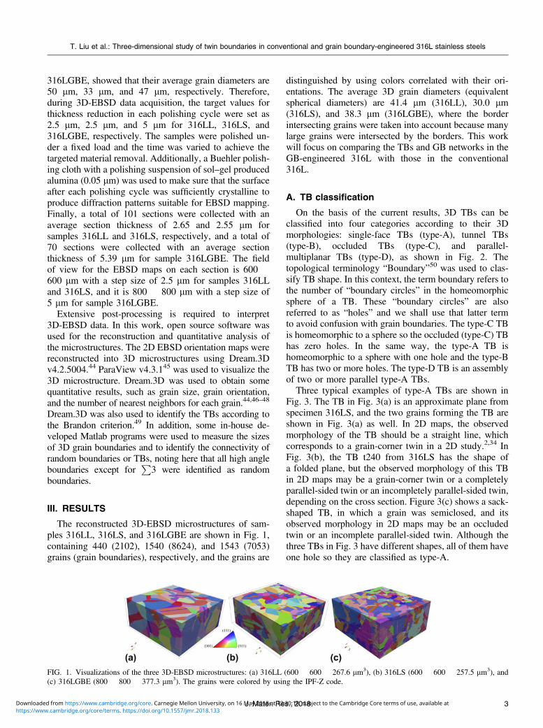
The reconstructed 3D-EBSD microstructures of sam-ples 316LL, 316LS, and 316LGBE are shown in Fig. 1,containing 440 (2102), 1540 (8624), and 1543 (7053)grains (grain boundaries), respectively, and the grains are
distinguished by using colors correlated with their ori-entations. The average 3D grain diameters (equivalentspherical diameters) are 41.4 lm (316LL), 30.0 lm(316LS), and 38.3 lm (316LGBE), where the borderintersecting grains were taken into account because manylarge grains were intersected by the borders. This workwill focus on comparing the TBs and GB networks in theGB-engineered 316L with those in the conventional316L.
A. TB classification
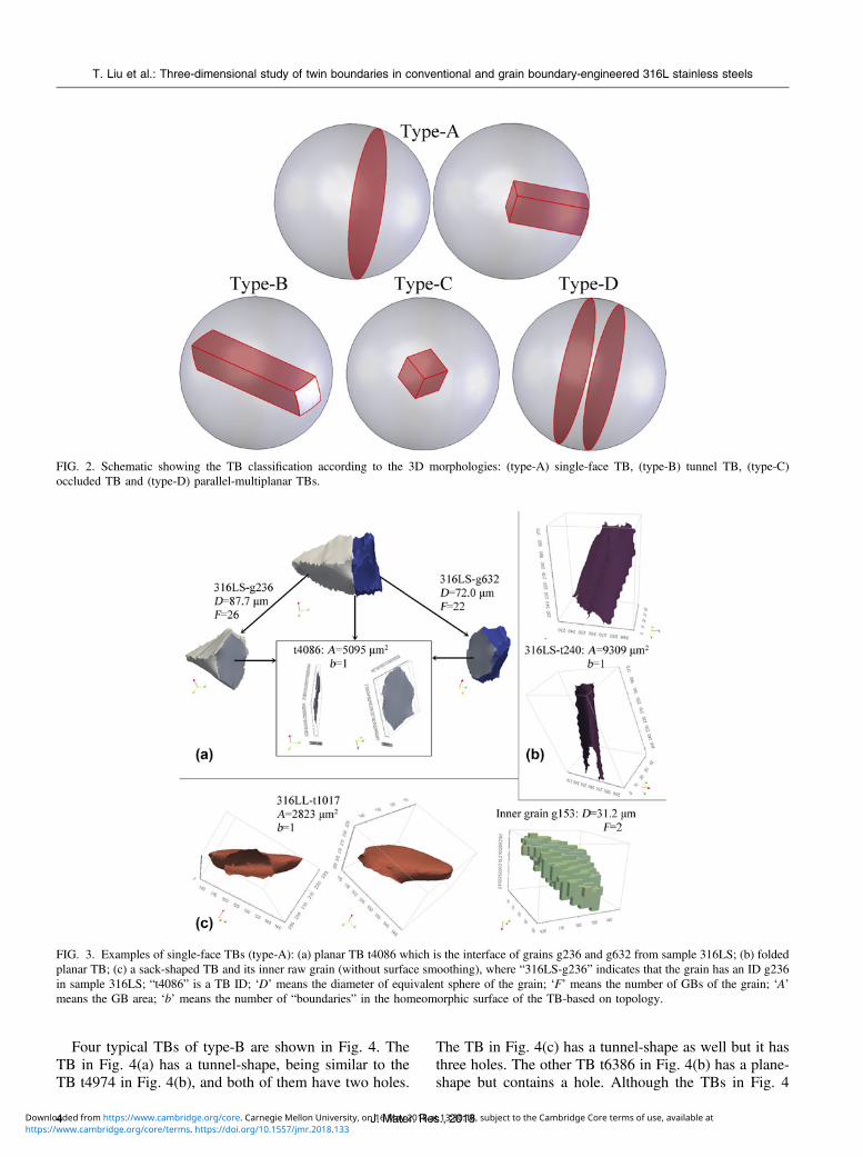
On the basis of the current results, 3D TBs can beclassified into four categories according to their 3Dmorphologies: single-face TBs (type-A), tunnel TBs(type-B), occluded TBs (type-C), and parallel-multiplanar TBs (type-D), as shown in Fig. 2. Thetopological terminology “Boundary”50 was used to clas-sify TB shape. In this context, the term boundary refers tothe number of “boundary circles” in the homeomorphicsphere of a TB. These “boundary circles” are alsoreferred to as “holes” and we shall use that latter termto avoid confusion with grain boundaries. The type-C TBis homeomorphic to a sphere so the occluded (type-C) TBhas zero holes. In the same way, the type-A TB ishomeomorphic to a sphere with one hole and the type-BTB has two or more holes. The type-D TB is an assemblyof two or more parallel type-A TBs.
Three typical examples of type-A TBs are shown inFig. 3. The TB in Fig. 3(a) is an approximate plane fromspecimen 316LS, and the two grains forming the TB areshown in Fig. 3(a) as well. In 2D maps, the observedmorphology of the TB should be a straight line, whichcorresponds to a grain-corner twin in a 2D study.2,34 InFig. 3(b), the TB t240 from 316LS has the shape ofa folded plane, but the observed morphology of this TBin 2D maps may be a grain-corner twin or a completelyparallel-sided twin or an incompletely parallel-sided twin,depending on the cross section. Figure 3(c) shows a sack-shaped TB, in which a grain was semiclosed, and itsobserved morphology in 2D maps may be an occludedtwin or an incomplete parallel-sided twin. Although thethree TBs in Fig. 3 have different shapes, all of them haveone hole so they are classified as type-A.
FIG. 1. Visualizations of the three 3D-EBSD microstructures: (a) 316LL (600 ! 600 ! 267.6 lm3), (b) 316LS (600 ! 600 ! 257.5 lm3), and(c) 316LGBE (800 ! 800 ! 377.3 lm3). The grains were colored by using the IPF-Z code.
T. Liu et al.: Three-dimensional study of twin boundaries in conventional and grain boundary-engineered 316L stainless steels
3J. Mater. Res., 20186 CCC 1/:0 7253 5 1 3 3 : 6 2 7 5 8: , C /232 : 6 CCC 1/:0 7253 5 1 3 / 3573 3 . 7 3 7 D /D / 0831 63 /:0 7253 3 3 : 3 / /7 /0 3 /
Four typical TBs of type-B are shown in Fig. 4. TheTB in Fig. 4(a) has a tunnel-shape, being similar to theTB t4974 in Fig. 4(b), and both of them have two holes.
The TB in Fig. 4(c) has a tunnel-shape as well but it hasthree holes. The other TB t6386 in Fig. 4(b) has a plane-shape but contains a hole. Although the TBs in Fig. 4
FIG. 2. Schematic showing the TB classification according to the 3D morphologies: (type-A) single-face TB, (type-B) tunnel TB, (type-C)occluded TB and (type-D) parallel-multiplanar TBs.
FIG. 3. Examples of single-face TBs (type-A): (a) planar TB t4086 which is the interface of grains g236 and g632 from sample 316LS; (b) foldedplanar TB; (c) a sack-shaped TB and its inner raw grain (without surface smoothing), where “316LS-g236” indicates that the grain has an ID g236in sample 316LS; “t4086” is a TB ID; ‘D’ means the diameter of equivalent sphere of the grain; ‘F’ means the number of GBs of the grain; ‘A’means the GB area; ‘b’ means the number of “boundaries” in the homeomorphic surface of the TB-based on topology.
T. Liu et al.: Three-dimensional study of twin boundaries in conventional and grain boundary-engineered 316L stainless steels
J. Mater. Res., 201846 CCC 1/:0 7253 5 1 3 3 : 6 2 7 5 8: , C /232 : 6 CCC 1/:0 7253 5 1 3 / 3573 3 . 7 3 7 D /D / 0831 63 /:0 7253 3 3 : 3 / /7 /0 3 /
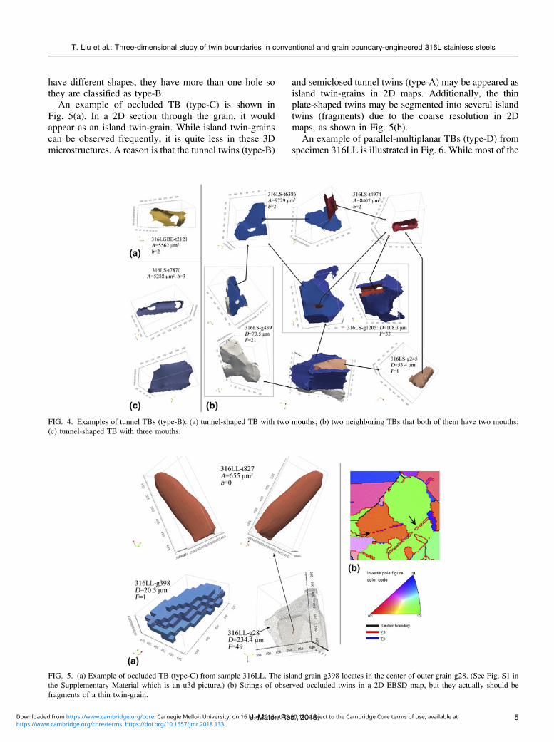
have different shapes, they have more than one hole sothey are classified as type-B.
An example of occluded TB (type-C) is shown inFig. 5(a). In a 2D section through the grain, it wouldappear as an island twin-grain. While island twin-grainscan be observed frequently, it is quite less in these 3Dmicrostructures. A reason is that the tunnel twins (type-B)
and semiclosed tunnel twins (type-A) may be appeared asisland twin-grains in 2D maps. Additionally, the thinplate-shaped twins may be segmented into several islandtwins (fragments) due to the coarse resolution in 2Dmaps, as shown in Fig. 5(b).
An example of parallel-multiplanar TBs (type-D) fromspecimen 316LL is illustrated in Fig. 6. While most of the
FIG. 4. Examples of tunnel TBs (type-B): (a) tunnel-shaped TB with two mouths; (b) two neighboring TBs that both of them have two mouths;(c) tunnel-shaped TB with three mouths.
FIG. 5. (a) Example of occluded TB (type-C) from sample 316LL. The island grain g398 locates in the center of outer grain g28. (See Fig. S1 inthe Supplementary Material which is an u3d picture.) (b) Strings of observed occluded twins in a 2D EBSD map, but they actually should befragments of a thin twin-grain.
T. Liu et al.: Three-dimensional study of twin boundaries in conventional and grain boundary-engineered 316L stainless steels
5J. Mater. Res., 20186 CCC 1/:0 7253 5 1 3 3 : 6 2 7 5 8: , C /232 : 6 CCC 1/:0 7253 5 1 3 / 3573 3 . 7 3 7 D /D / 0831 63 /:0 7253 3 3 : 3 / /7 /0 3 /
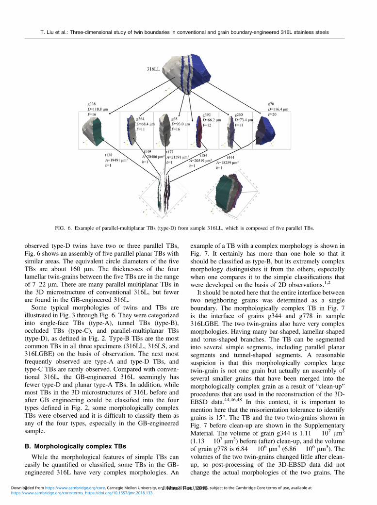
observed type-D twins have two or three parallel TBs,Fig. 6 shows an assembly of five parallel planar TBs withsimilar areas. The equivalent circle diameters of the fiveTBs are about 160 lm. The thicknesses of the fourlamellar twin-grains between the five TBs are in the rangeof 7–22 lm. There are many parallel-multiplanar TBs inthe 3D microstructure of conventional 316L, but fewerare found in the GB-engineered 316L.
Some typical morphologies of twins and TBs areillustrated in Fig. 3 through Fig. 6. They were categorizedinto single-face TBs (type-A), tunnel TBs (type-B),occluded TBs (type-C), and parallel-multiplanar TBs(type-D), as defined in Fig. 2. Type-B TBs are the mostcommon TBs in all three specimens (316LL, 316LS, and316LGBE) on the basis of observation. The next mostfrequently observed are type-A and type-D TBs, andtype-C TBs are rarely observed. Compared with conven-tional 316L, the GB-engineered 316L seemingly hasfewer type-D and planar type-A TBs. In addition, whilemost TBs in the 3D microstructures of 316L before andafter GB engineering could be classified into the fourtypes defined in Fig. 2, some morphologically complexTBs were observed and it is difficult to classify them asany of the four types, especially in the GB-engineeredsample.
B. Morphologically complex TBs
While the morphological features of simple TBs caneasily be quantified or classified, some TBs in the GB-engineered 316L have very complex morphologies. An
example of a TB with a complex morphology is shown inFig. 7. It certainly has more than one hole so that itshould be classified as type-B, but its extremely complexmorphology distinguishes it from the others, especiallywhen one compares it to the simple classifications thatwere developed on the basis of 2D observations.1,2
It should be noted here that the entire interface betweentwo neighboring grains was determined as a singleboundary. The morphologically complex TB in Fig. 7is the interface of grains g344 and g778 in sample316LGBE. The two twin-grains also have very complexmorphologies. Having many bar-shaped, lamellar-shapedand torus-shaped branches. The TB can be segmentedinto several simple segments, including parallel planarsegments and tunnel-shaped segments. A reasonablesuspicion is that this morphologically complex largetwin-grain is not one grain but actually an assembly ofseveral smaller grains that have been merged into themorphologically complex grain as a result of “clean-up”procedures that are used in the reconstruction of the 3D-EBSD data.44,46,48 In this context, it is important tomention here that the misorientation tolerance to identifygrains is 15°. The TB and the two twin-grains shown inFig. 7 before clean-up are shown in the SupplementaryMaterial. The volume of grain g344 is 1.11 ! 107 lm3
(1.13 ! 107 lm3) before (after) clean-up, and the volumeof grain g778 is 6.84 ! 106 lm3 (6.86 ! 106 lm3). Thevolumes of the two twin-grains changed little after clean-up, so post-processing of the 3D-EBSD data did notchange the actual morphologies of the two grains. The
FIG. 6. Example of parallel-multiplanar TBs (type-D) from sample 316LL, which is composed of five parallel TBs.
T. Liu et al.: Three-dimensional study of twin boundaries in conventional and grain boundary-engineered 316L stainless steels
J. Mater. Res., 201866 CCC 1/:0 7253 5 1 3 3 : 6 2 7 5 8: , C /232 : 6 CCC 1/:0 7253 5 1 3 / 3573 3 . 7 3 7 D /D / 0831 63 /:0 7253 3 3 : 3 / /7 /0 3 /
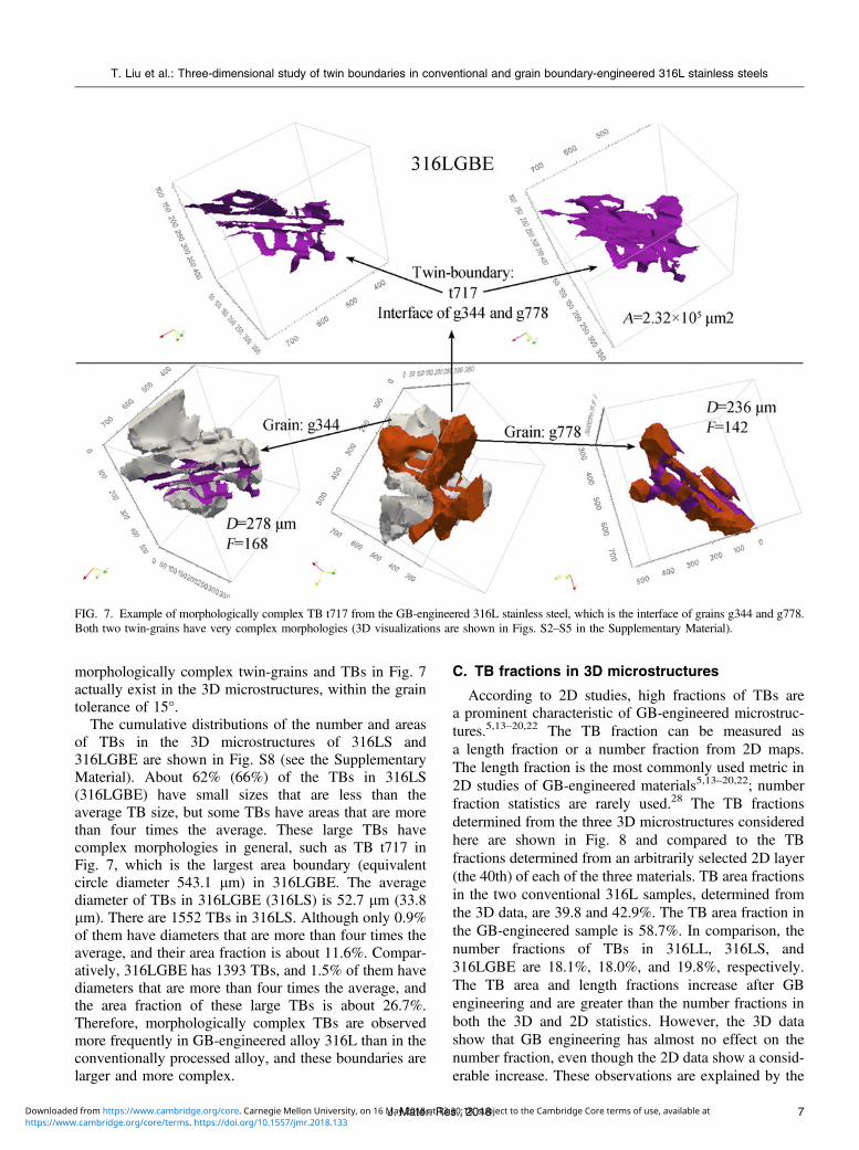
morphologically complex twin-grains and TBs in Fig. 7actually exist in the 3D microstructures, within the graintolerance of 15°.
The cumulative distributions of the number and areasof TBs in the 3D microstructures of 316LS and316LGBE are shown in Fig. S8 (see the SupplementaryMaterial). About 62% (66%) of the TBs in 316LS(316LGBE) have small sizes that are less than theaverage TB size, but some TBs have areas that are morethan four times the average. These large TBs havecomplex morphologies in general, such as TB t717 inFig. 7, which is the largest area boundary (equivalentcircle diameter 543.1 lm) in 316LGBE. The averagediameter of TBs in 316LGBE (316LS) is 52.7 lm (33.8lm). There are 1552 TBs in 316LS. Although only 0.9%of them have diameters that are more than four times theaverage, and their area fraction is about 11.6%. Compar-atively, 316LGBE has 1393 TBs, and 1.5% of them havediameters that are more than four times the average, andthe area fraction of these large TBs is about 26.7%.Therefore, morphologically complex TBs are observedmore frequently in GB-engineered alloy 316L than in theconventionally processed alloy, and these boundaries arelarger and more complex.
C. TB fractions in 3D microstructures
According to 2D studies, high fractions of TBs area prominent characteristic of GB-engineered microstruc-tures.5,13–20,22 The TB fraction can be measured asa length fraction or a number fraction from 2D maps.The length fraction is the most commonly used metric in2D studies of GB-engineered materials5,13–20,22; numberfraction statistics are rarely used.28 The TB fractionsdetermined from the three 3D microstructures consideredhere are shown in Fig. 8 and compared to the TBfractions determined from an arbitrarily selected 2D layer(the 40th) of each of the three materials. TB area fractionsin the two conventional 316L samples, determined fromthe 3D data, are 39.8 and 42.9%. The TB area fraction inthe GB-engineered sample is 58.7%. In comparison, thenumber fractions of TBs in 316LL, 316LS, and316LGBE are 18.1%, 18.0%, and 19.8%, respectively.The TB area and length fractions increase after GBengineering and are greater than the number fractions inboth the 3D and 2D statistics. However, the 3D datashow that GB engineering has almost no effect on thenumber fraction, even though the 2D data show a consid-erable increase. These observations are explained by the
FIG. 7. Example of morphologically complex TB t717 from the GB-engineered 316L stainless steel, which is the interface of grains g344 and g778.Both two twin-grains have very complex morphologies (3D visualizations are shown in Figs. S2–S5 in the Supplementary Material).
T. Liu et al.: Three-dimensional study of twin boundaries in conventional and grain boundary-engineered 316L stainless steels
7J. Mater. Res., 20186 CCC 1/:0 7253 5 1 3 3 : 6 2 7 5 8: , C /232 : 6 CCC 1/:0 7253 5 1 3 / 3573 3 . 7 3 7 D /D / 0831 63 /:0 7253 3 3 : 3 / /7 /0 3 /
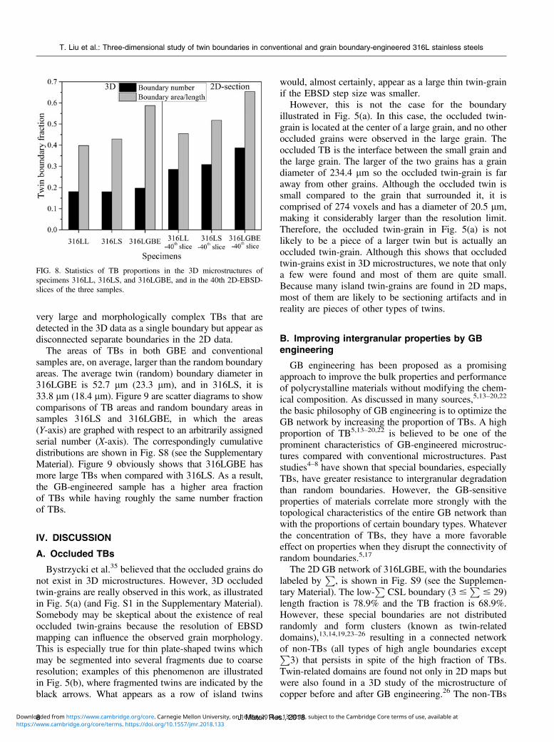
very large and morphologically complex TBs that aredetected in the 3D data as a single boundary but appear asdisconnected separate boundaries in the 2D data.
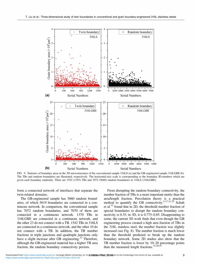
The areas of TBs in both GBE and conventionalsamples are, on average, larger than the random boundaryareas. The average twin (random) boundary diameter in316LGBE is 52.7 lm (23.3 lm), and in 316LS, it is33.8 lm (18.4 lm). Figure 9 are scatter diagrams to showcomparisons of TB areas and random boundary areas insamples 316LS and 316LGBE, in which the areas(Y-axis) are graphed with respect to an arbitrarily assignedserial number (X-axis). The correspondingly cumulativedistributions are shown in Fig. S8 (see the SupplementaryMaterial). Figure 9 obviously shows that 316LGBE hasmore large TBs when compared with 316LS. As a result,the GB-engineered sample has a higher area fractionof TBs while having roughly the same number fractionof TBs.
IV. DISCUSSION
A. Occluded TBs
Bystrzycki et al.35 believed that the occluded grains donot exist in 3D microstructures. However, 3D occludedtwin-grains are really observed in this work, as illustratedin Fig. 5(a) (and Fig. S1 in the Supplementary Material).Somebody may be skeptical about the existence of realoccluded twin-grains because the resolution of EBSDmapping can influence the observed grain morphology.This is especially true for thin plate-shaped twins whichmay be segmented into several fragments due to coarseresolution; examples of this phenomenon are illustratedin Fig. 5(b), where fragmented twins are indicated by theblack arrows. What appears as a row of island twins
would, almost certainly, appear as a large thin twin-grainif the EBSD step size was smaller.
However, this is not the case for the boundaryillustrated in Fig. 5(a). In this case, the occluded twin-grain is located at the center of a large grain, and no otheroccluded grains were observed in the large grain. Theoccluded TB is the interface between the small grain andthe large grain. The larger of the two grains has a graindiameter of 234.4 lm so the occluded twin-grain is faraway from other grains. Although the occluded twin issmall compared to the grain that surrounded it, it iscomprised of 274 voxels and has a diameter of 20.5 lm,making it considerably larger than the resolution limit.Therefore, the occluded twin-grain in Fig. 5(a) is notlikely to be a piece of a larger twin but is actually anoccluded twin-grain. Although this shows that occludedtwin-grains exist in 3D microstructures, we note that onlya few were found and most of them are quite small.Because many island twin-grains are found in 2D maps,most of them are likely to be sectioning artifacts and inreality are pieces of other types of twins.
B. Improving intergranular properties by GBengineering
GB engineering has been proposed as a promisingapproach to improve the bulk properties and performanceof polycrystalline materials without modifying the chem-ical composition. As discussed in many sources,5,13–20,22
the basic philosophy of GB engineering is to optimize theGB network by increasing the proportion of TBs. A highproportion of TB5,13–20,22 is believed to be one of theprominent characteristics of GB-engineered microstruc-tures compared with conventional microstructures. Paststudies4–8 have shown that special boundaries, especiallyTBs, have greater resistance to intergranular degradationthan random boundaries. However, the GB-sensitiveproperties of materials correlate more strongly with thetopological characteristics of the entire GB network thanwith the proportions of certain boundary types. Whateverthe concentration of TBs, they have a more favorableeffect on properties when they disrupt the connectivity ofrandom boundaries.5,17
The 2D GB network of 316LGBE, with the boundarieslabeled by
P, is shown in Fig. S9 (see the Supplemen-
tary Material). The low-P
CSL boundary (3 #P
# 29)length fraction is 78.9% and the TB fraction is 68.9%.However, these special boundaries are not distributedrandomly and form clusters (known as twin-relateddomains),13,14,19,23–26 resulting in a connected networkof non-TBs (all types of high angle boundaries exceptP
3) that persists in spite of the high fraction of TBs.Twin-related domains are found not only in 2D maps butwere also found in a 3D study of the microstructure ofcopper before and after GB engineering.26 The non-TBs
FIG. 8. Statistics of TB proportions in the 3D microstructures ofspecimens 316LL, 316LS, and 316LGBE, and in the 40th 2D-EBSD-slices of the three samples.
T. Liu et al.: Three-dimensional study of twin boundaries in conventional and grain boundary-engineered 316L stainless steels
J. Mater. Res., 201886 CCC 1/:0 7253 5 1 3 3 : 6 2 7 5 8: , C /232 : 6 CCC 1/:0 7253 5 1 3 / 3573 3 . 7 3 7 D /D / 0831 63 /:0 7253 3 3 : 3 / /7 /0 3 /
form a connected network of interfaces that separate thetwin-related domains.
The GB-engineered sample has 5660 random bound-aries, of which 5619 boundaries are connected in a con-tinuous network. In comparison, the conventional samplehas 7072 random boundaries, and 7070 of them areconnected in a continuous network. 1370 TBs in316LGBE are connected in a continuous network, andthe other 23 do not connect with a TB. 1542 TBs in 316LSare connected in a continuous network, and the other 10 donot connect with a TB. In addition, the TB numberfractions in triple junctions and quadruple junctions onlyhave a slight increase after GB engineering.33 Therefore,although the GB-engineered material has a higher TB areafraction, the random boundary connectivity persists.
From disrupting the random boundary connectivity, thenumber fraction of TBs is a more important metric than thearea/length fraction. Percolation theory is a practicalmethod to quantify the GB connectivity.5,17,31,32 Schuhet al.32 found that in 2D, the threshold number fraction ofspecial boundaries to disrupt the random boundary con-nectivity is 0.35; in 3D, it is 0.775–0.85. Disappointing tosome, the current 3D work finds that even though the GBengineering process created a high area fraction of TBs inthe 316L stainless steel, the number fraction was slightlyincreased (see Fig. 8). The number fraction is much lowerthan the threshold predicted to break up the randomboundary network. Some 2D studies also show that theTB number fraction is lower by 10–20 percentage pointsthan the measured length fractions.15,28,51
FIG. 9. Statistics of boundary areas in the 3D microstructures of the conventional sample 316LS (a) and the GB-engineered sample 316LGBE (b).The TBs and random boundaries are illustrated, respectively. The horizontal-axis scale is corresponding to the boundary ID-numbers which aregiven each boundary randomly. There are 1552 (1393) TBs and 7072 (5660) random boundaries in 316LS (316LGBE).
T. Liu et al.: Three-dimensional study of twin boundaries in conventional and grain boundary-engineered 316L stainless steels
9J. Mater. Res., 20186 CCC 1/:0 7253 5 1 3 3 : 6 2 7 5 8: , C /232 : 6 CCC 1/:0 7253 5 1 3 / 3573 3 . 7 3 7 D /D / 0831 63 /:0 7253 3 3 : 3 / /7 /0 3 /
In summary, the random GB network was not thor-oughly disrupted after GB engineering although the TBarea fraction increased significantly. The reason is thatthe TB number fraction increased by only a smallamount. Large, morphologically complex TBs are re-sponsible for the difference between the number and areafraction. New procedures for GB engineering should bedeveloped in future to produce a high proportion of TBsnot only in length/area but also in number. To reach thegoal, it is necessary to understand the formation mech-anism of the large morphologically complex TBs.
C. Formation mechanisms of TBs during GBengineering
As discussed above, the high area fraction of TBs inthe GB-engineered 316L results from the formation ofmany large morphologically complex TBs that separateequally complex twinned grins (see Fig. 7). Although theformation of these twins or TBs is undesired, theformation mechanism is an interesting issue.
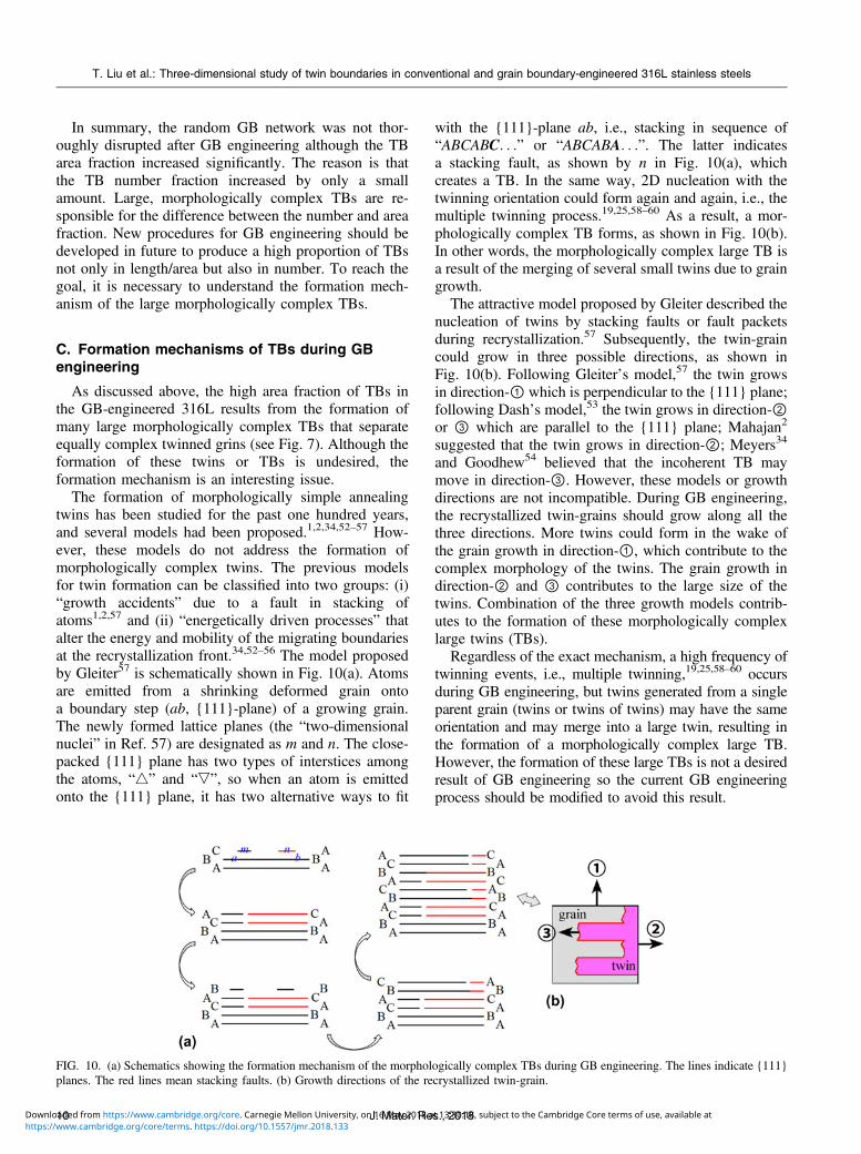
The formation of morphologically simple annealingtwins has been studied for the past one hundred years,and several models had been proposed.1,2,34,52–57 How-ever, these models do not address the formation ofmorphologically complex twins. The previous modelsfor twin formation can be classified into two groups: (i)“growth accidents” due to a fault in stacking ofatoms1,2,57 and (ii) “energetically driven processes” thatalter the energy and mobility of the migrating boundariesat the recrystallization front.34,52–56 The model proposedby Gleiter57 is schematically shown in Fig. 10(a). Atomsare emitted from a shrinking deformed grain ontoa boundary step (ab, {111}-plane) of a growing grain.The newly formed lattice planes (the “two-dimensionalnuclei” in Ref. 57) are designated as m and n. The close-packed {111} plane has two types of interstices amongthe atoms, “4” and “,”, so when an atom is emittedonto the {111} plane, it has two alternative ways to fit
with the {111}-plane ab, i.e., stacking in sequence of“ABCABC. . .” or “ABCABA. . .”. The latter indicatesa stacking fault, as shown by n in Fig. 10(a), whichcreates a TB. In the same way, 2D nucleation with thetwinning orientation could form again and again, i.e., themultiple twinning process.19,25,58–60 As a result, a mor-phologically complex TB forms, as shown in Fig. 10(b).In other words, the morphologically complex large TB isa result of the merging of several small twins due to graingrowth.
The attractive model proposed by Gleiter described thenucleation of twins by stacking faults or fault packetsduring recrystallization.57 Subsequently, the twin-graincould grow in three possible directions, as shown inFig. 10(b). Following Gleiter’s model,57 the twin growsin direction-① which is perpendicular to the {111} plane;following Dash’s model,53 the twin grows in direction-②or ③ which are parallel to the {111} plane; Mahajan2
suggested that the twin grows in direction-②; Meyers34
and Goodhew54 believed that the incoherent TB maymove in direction-③. However, these models or growthdirections are not incompatible. During GB engineering,the recrystallized twin-grains should grow along all thethree directions. More twins could form in the wake ofthe grain growth in direction-①, which contribute to thecomplex morphology of the twins. The grain growth indirection-② and ③ contributes to the large size of thetwins. Combination of the three growth models contrib-utes to the formation of these morphologically complexlarge twins (TBs).
Regardless of the exact mechanism, a high frequency oftwinning events, i.e., multiple twinning,19,25,58–60 occursduring GB engineering, but twins generated from a singleparent grain (twins or twins of twins) may have the sameorientation and may merge into a large twin, resulting inthe formation of a morphologically complex large TB.However, the formation of these large TBs is not a desiredresult of GB engineering so the current GB engineeringprocess should be modified to avoid this result.
FIG. 10. (a) Schematics showing the formation mechanism of the morphologically complex TBs during GB engineering. The lines indicate {111}planes. The red lines mean stacking faults. (b) Growth directions of the recrystallized twin-grain.
T. Liu et al.: Three-dimensional study of twin boundaries in conventional and grain boundary-engineered 316L stainless steels
J. Mater. Res., 2018106 CCC 1/:0 7253 5 1 3 3 : 6 2 7 5 8: , C /232 : 6 CCC 1/:0 7253 5 1 3 / 3573 3 . 7 3 7 D /D / 0831 63 /:0 7253 3 3 : 3 / /7 /0 3 /
Three types of thermomechanical processing arewidely used for GB engineering: strain and annealingat high temperature for a short time,5,13,14,24,25,61–63
strain and annealing at a relatively low temperature fora long time,5,17,31,64 and repeated strain and annealingfor several cycles.15,28,36,62,63 The first type was used inthis work, and it is an economical method compared tothe other two methods and suitable for industrialapplication. In general, long annealing times or iterativethermomechanical processing could produce a higherproportion of TBs. However, based on the microstruc-tures illustrated in Refs. 15, 17, and 36, these twomethods do not prevent the formation of the morpho-logically complex TBs. Therefore, although most paperson GB engineering equate success with developinga high area/length fraction of special boundaries, de-veloping a new procedure that could increase thenumber fraction is still important in future from theperspective of disrupting the random boundaryconnectivity.
V. CONCLUSIONS
The morphology, connectivity, and TB fractions ina GB-engineered austenitic stainless steel have beenmeasured from 3D microstructure data and comparedwith those of conventional samples of the same material.The main findings are as follows:
(1) Morphologically simple TBs can be classified intofour categories: (type-A) single-face TBs, (type-B) tunnelTBs, (type-C) occluded TBs, and (type-D) parallel-multiplanar TBs. In the order of most to least common,are TBs of type-B, type-A, type-D, and type-C. Thisorder is found in both the conventional and GB-engineered samples. The GB-engineered sample hasa higher fraction of type-B TBs and a lower fraction oftype-D TBs than the conventional sample.
(2) Compared with the conventional samples, a prom-inent characteristic of the GB-engineered microstructureis the formation of some large and morphologicallycomplex TBs. This leads to a higher area fraction ofTBs in the GB-engineered sample. However, the numberfraction of TBs in the GB-engineered sample is notsignificantly different than the conventional sample. Theconnectivity of random boundaries (or non-TBs) was notdisrupted thoroughly by GB engineering.
ACKNOWLEDGMENTS
This work was supported by the National NaturalScience Foundation of China (Grant Nos. 51671122and 51701017) and the Fund of Jiangsu Province forthe Transformation of Scientific and TechnologicalAchievements (BA2017126).
REFERENCES
1. H.C.H. Carpenter and S. Tamura: The formation of twinnedmetallic crystals. Proc. R. Soc. London 113, 161 (1926).
2. S. Mahajan, C.S. Pande, M.A. Imam, and B.B. Rath: Formation ofannealing twins in f.c.c. crystals. Acta Mater. 45, 2633 (1997).
3. H. Li, S. Xia, B. Zhou, W. Chen, and C. Hu: The dependence ofcarbide morphology on grain boundary character in the highlytwinned alloy 690. J. Nucl. Mater. 399, 108 (2010).
4. P. Lin, G. Palumbo, U. Erb, and K.T. Aust: Influence of grainboundary character distribution on sensitization and intergranularcorrosion of alloy 600. Scr. Metall. Mater. 33, 1387 (1995).
5. M. Michiuchi, H. Kokawa, Z.J. Wang, Y.S. Sato, and K. Sakai:Twin-induced grain boundary engineering for 316 austeniticstainless steel. Acta Mater. 54, 5179 (2006).
6. L. Tan, T.R. Allen, and J.T. Busby: Grain boundary engineeringfor structure materials of nuclear reactors. J. Nucl. Mater. 441, 661(2013).
7. C.L. Hu, S. Xi, H. Li, T.G. Liu, B.X. Zhou, W.J. Chen, andN. Wang: Improving the intergranular corrosion resistance of 304stainless steel by grain boundary network control. Corros. Sci. 53,1880 (2011).
8. S. Xia, H. Li, T.G. Liu, and B.X. Zhou: Appling grain boundaryengineering to alloy 690 tube for enhancing intergranular corro-sion resistance. J. Nucl. Mater. 416, 303 (2011).
9. E.A. West and G.S. Was: IGSCC of grain boundary engineered316L and 690 in supercritical water. J. Nucl. Mater. 392, 264(2009).
10. V.Y. Gertsman and S.M. Bruemmer: Study of grain boundarycharacter along intergranular stress corrosion crack paths inaustenitic alloys. Acta Mater. 49, 1589 (2001).
11. D.L. Engelberg, T.J. Marrow, R.C. Newman, and L. Babouta:Grain boundary engineering for crack bridging: A new model forintergranular stress corrosion crack (IGSCC) propagation. InEnvironment-Induced Cracking of Materials, S.A. Shipilov,R.H. Jones, J.-M. Olive, and R.B. Rebak, eds. (Elsevier, Amsterdam,Netherlands, 2008); pp. 69–79.
12. T. Watanabe: Approch to grain boundary design for strong andductile polycrystals. Res Mech. 11, 47 (1984).
13. T.G. Liu, S. Xia, H. Li, B.X. Zhou, Q. Bai, C. Su, and Z.G. Cai:Effect of initial grain sizes on the grain boundary network duringgrain boundary engineering in alloy 690. J. Mater. Res. 28, 1165(2013).
14. T.G. Liu, S. Xia, H. Li, B.X. Zhou, and Q. Bai: Effect of the pre-existing carbides on the grain boundary network during grainboundary engineering in a nickel based alloy. Mater. Charact. 91,89 (2014).
15. V. Randle and M. Coleman: A study of low-strain and medium-strain grain boundary engineering. Acta Mater. 57, 3410–3421(2009).
16. V. Randle: Mechanism of twinning-induced grain boundaryengineering in low stacking-fault energy materials. Acta Mater.47, 4187 (1999).
17. S. Kobayashi, R. Kobayashi, and T. Watanabe: Control of grainboundary connectivity based on fractal analysis for improvementof intergranular corrosion resistance in SUS316L austenitic stain-less steel. Acta Mater. 102, 397 (2016).
18. X. Wang, A. Dallemagne, Y. Hou, and S. Yang: Effect ofthermomechanical processing on grain boundary character dis-tribution of Hastelloy X alloy. Mater. Sci. Eng., A 669, 95(2016).
19. S. Xia, B.X. Zhou, and W.J. Chen: Grain cluster microstructureand grain boundary character distribution in alloy 690. Metall.Mater. Trans. A 40, 3016 (2009).
20. W. Cao, S. Xia, Q. Bai, W. Zhang, B. Zhou, Z. Li, and L. Jiang:Effects of initial microstructure on the grain boundary network
T. Liu et al.: Three-dimensional study of twin boundaries in conventional and grain boundary-engineered 316L stainless steels
11J. Mater. Res., 20186 CCC 1/:0 7253 5 1 3 3 : 6 2 7 5 8: , C /232 : 6 CCC 1/:0 7253 5 1 3 / 3573 3 . 7 3 7 D /D / 0831 63 /:0 7253 3 3 : 3 / /7 /0 3 /
during grain boundary engineering in Hastelloy N alloy. J. AlloysCompd. 704, 724 (2017).
21. D.L. Engelberg, R.C. Newman, and T.J. Marrow: Effect ofthermomechanical process history on grain boundary control inan austenitic stainless steel. Scripta Mater. 59, 554 (2008).
22. S.S. Katnagallu, S. Mandal, A.C. Nagaraja, B. De Boer, andS.S. Vadlamani: Role of carbide precipitates and processparameters on achieving grain boundary engineered microstruc-ture in a Ni-based superalloy. Metall. Mater. Trans. A 46, 4740(2015).
23. V.Y. Gertsman and C.H. Henager: Grain boundary junctions inmicrostructure generated by multiple twinning. Interface Sci. 11,403 (2003).
24. T.G. Liu, S. Xia, H. Li, B.X. Zhou, and Q. Bai: The highlytwinned grain boundary network formation during grain boundaryengineering. Mater. Lett. 133, 97 (2014).
25. T. Liu, S. Xia, B. Wang, Q. Bai, B. Zhou, and C. Su: Grainorientation statistics of grain-clusters and the propensity ofmultiple-twinning during grain boundary engineering. Mater.Des. 112, 442 (2016).
26. J. Lind, S.F. Li, and M. Kumar: Twin related domains in 3Dmicrostructures of conventionally processed and grain boundaryengineered materials. Acta Mater. 114, 43 (2016).
27. C.M. Barr, A.C. Leff, R.W. Demott, R.D. Doherty, andM.L. Taheri: Unraveling the origin of twin related domains andgrain boundary evolution during grain boundary engineering. ActaMater. 144, 281 (2018).
28. M. Kumar, W.E. King, and A.J. Schwartz: Modifications to themicrostructural topology in f.c.c. materials through thermome-chanical processing. Acta Mater. 48, 2081 (2000).
29. G. Palumbo, P.J. King, K.T. Aust, U. Erb, andP.C. Lichtenberger: Grain boundary design and control forintergranular stress-corrosion resistance. Scr. Metall. Mater.25, 1775 (1991).
30. S. Tsurekawa, S. Nakamichi, and T. Watanabe: Correlation ofgrain boundary connectivity with grain boundary characterdistribution in austenitic stainless steel. Acta Mater. 54, 3617(2006).
31. S. Tokita, H. Kokawa, Y.S. Sato, and H.T. Fujii: In situ EBSDobservation of grain boundary character distribution evolutionduring thermomechanical process used for grain boundary engi-neering of 304 austenitic stainless steel. Mater. Charact. 131, 31(2017).
32. M. Frary and C.A. Schuh: Connectivity and percolation behaviourof grain boundary networks in three dimensions. Philos. Mag. 85,1123 (2005).
33. T. Liu, S. Xia, B. Zhou, Q. Bai, and G.S. Rohrer: Three-dimensional characteristics of the grain boundary networks ofconventional and grain boundary engineered 316L stainless steel.Mater. Charact. 133, 60 (2017).
34. M.A. Meyers and L.E. Murr: A model for the formation ofannealing twins in F.C.C. metals and alloys. Acta Metall. 26, 951(1978).
35. J. Bystrzycki and W. Przetakiewicz: 3-Dimensional reconstructionof annealing twins shape in FCC metals by serial sectioning. Scr.Metall. Mater. 27, 893 (1992).
36. A. Telang, A.S. Gill, M. Kumar, S. Teysseyre, D. Qian,S.R. Mannava, and V.K. Vasudevan: Iterative thermomechanicalprocessing of alloy 600 for improved resistance to corrosion andstress corrosion cracking. Acta Mater. 113, 180 (2016).
37. M.N. Kelly, K. Glowinski, N.T. Nuhfer, and G.S. Rohrer: The fiveparameter grain boundary character distribution of a-Ti deter-mined from three-dimensional orientation data. Acta Mater. 111,22 (2016).
38. J. Konrad, S. Zaefferer, and D. Raabe: Investigation of orientationgradients around a hard Laves particle in a warm-rolled Fe3Al-based alloy using a 3D EBSD-FIB technique. Acta Mater. 54,1369 (2006).
39. M.D. Uchic, M.A. Groeber, D.M. Dimiduk, and J.P. Simmons:3D microstructural characterization of nickel superalloys viaserial-sectioning using a dual beam FIB-SEM. Scr. Mater. 55, 23(2006).
40. A.C. Lewis, J.F. Bingert, D.J. Rowenhorst, A. Gupta,A.B. Geltmacher, and G. Spanos: Two- and three-dimensionalmicrostructural characterization of a super-austenitic stainlesssteel. Mat. Sci. Eng., A 418, 11 (2006).
41. D.J. Rowenhorst, A.C. Lewis, and G. Spanos: Three-dimensionalanalysis of grain topology and interface curvature in a beta-titanium alloy. Acta Mater. 58, 5511 (2010).
42. F.X. Lin, A. Godfrey, D.J. Jensen, and G. Winther: 3D EBSDcharacterization of deformation structures in commercial purityaluminum. Mater. Charact. 61, 1203 (2010).
43. J.E. Spowart: Automated serial sectioning for 3-D analysis ofmicrostructures. Scr. Mater. 55, 5 (2006).
44. M. Groeber and M. Jackson: DREAM.3D: A digital representationenvironment for the analysis of microstructure in 3D. Integr.Mater. Manuf. Innov. 3, 1 (2014).
45. U. Ayachit: The ParaView Guide: A Parallel VisualizationApplication (Published by Kitware, Clifton Park, NY, 2015); pp.1–276.
46. M. Groeber, S. Ghosh, M.D. Uchic, and D.M. Dimiduk: Aframework for automated analysis and simulation of 3D poly-crystalline microstructures: Part 1: Statistical characterization.Acta Mater. 56, 1257 (2008).
47. M. Groeber, S. Ghosh, M. Uchic, and D. Dimiduk: A frameworkfor automated analysis and simulation of 3d polycrystallinemicrostructures. Part 2: Synthetic structure generation. Acta Mater.56, 1275 (2008).
48. Y. Bhandari, S. Sarkar, M. Groeber, M.D. Uchic, D.M. Dimiduk,and S. Ghosh: 3D polycrystalline microstructure reconstructionfrom FIB generated serial sections for FE analysis. Comput.Mater. Sci. 41, 222 (2007).
49. D.G. Brandon: The structure of high-angle grain boundaries. ActaMetall. 14, 1479 (1966).
50. M.A. Armstrong: Basic Topology (Published by Springer, Berlin,2010); pp. 115–161.
51. V. Randle: Twinning-related grain boundary engineering. ActaMater. 52, 4067–4081 (2004).
52. R.L. Fullman and J.C. Fisher: Formation of annealing twins duringgrain growth. J. Appl. Phys. 22, 1350 (1951).
53. S. Dash and N. Brown: An investigation of the origin and growthof annealing twins. Acta Metall. 11, 1067 (1963).
54. P.J. Goodhew: Annealing twin formation by boundary dissocia-tion. Met. Sci. 13, 108 (1979).
55. P. Haasen: How are new orientations generated during primaryrecrystallization? MTA 24, 1001 (1993).
56. D.P. Field, L.T. Bradford, M.M. Nowell, and T.M. Lillo: The roleof annealing twins during recrystallization of Cu. Acta Mater. 55,4233 (2007).
57. H. Gleiter: The formation of annealing twins. Acta Metall. 17,1421 (1969).
58. G. Gottstein: Annealing texture development by multiple twinningin f.c.c. crystals. Acta Metall. 32, 1117 (1984).
59. B.W. Reed and M. Kumar: Mathematical methods for analyzinghighly-twinned grain boundary networks. Scr. Mater. 54, 1029(2006).
60. C. Cayron: Quantification of multiple twinning in face centredcubic materials. Acta Mater. 59, 252 (2011).
T. Liu et al.: Three-dimensional study of twin boundaries in conventional and grain boundary-engineered 316L stainless steels
J. Mater. Res., 2018126 CCC 1/:0 7253 5 1 3 3 : 6 2 7 5 8: , C /232 : 6 CCC 1/:0 7253 5 1 3 / 3573 3 . 7 3 7 D /D / 0831 63 /:0 7253 3 3 : 3 / /7 /0 3 /
61. K. Deepak, S. Mandal, C.N. Athreya, D-I. Kim, B.d. Boer, andV. Subramanya Sarma: Implication of grain boundary engineeringon high temperature hot corrosion of alloy 617. Corros. Sci. 106,293 (2016).
62. V. Randle and R. Jones: Grain boundary plane distributions andsingle-step versus multiple-step grain boundary engineering.Mater. Sci. Eng., A 524, 134 (2009).
63. L. Tan, K. Sridharan, and T.R. Allen: Effect of thermomechanicalprocessing on grain boundary character distribution of a Ni-basedsuperalloy. J. Nucl. Mater. 371, 171 (2007).
64. M. Shimada, H. Kokawa, Z.J. Wang, Y.S. Sato, and I. Karibe:Optimization of grain boundary character distribution for inter-granular corrosion resistant 304 stainless steel by twin-inducedgrain boundary engineering. Acta Mater. 50, 2331 (2002).
Supplementary Material
To view supplementary material for this article, please visit https://doi.org/10.1557/jmr.2018.133.
T. Liu et al.: Three-dimensional study of twin boundaries in conventional and grain boundary-engineered 316L stainless steels
13J. Mater. Res., 20186 CCC 1/:0 7253 5 1 3 3 : 6 2 7 5 8: , C /232 : 6 CCC 1/:0 7253 5 1 3 / 3573 3 . 7 3 7 D /D / 0831 63 /:0 7253 3 3 : 3 / /7 /0 3 /
![Metastable monoclinic [110] layered perovskite Dy2Ti2O7 ...mimp.materials.cmu.edu/rohrer/papers/2019_06.pdf · 6 octa-hedra network. In the monoclinic layered perovskite structure,](https://img.pdfslide.us/doc/110x75/5e88ba593f2a6242127ea256/metastable-monoclinic-110-layered-perovskite-dy2ti2o7-mimp-6-octa-hedra-network.jpg)


![Three-dimensional characteristics of the grain boundary networks …mimp.materials.cmu.edu/rohrer/papers/2017_19.pdf · 2017-12-16 · Grain boundary (GB) engineering [1–9] has](https://img.pdfslide.us/doc/110x75/5f0430627e708231d40cc093/three-dimensional-characteristics-of-the-grain-boundary-networks-mimp-2017-12-16.jpg)