Embed Size (px)
Citation preview
Article
Steel Frames Exposed to Severe Ground Motions: Use of Vis-
cous Dampers and Buckling Restrained Braces to Dissipate
Earthquake Induced Energy
Osman Hansu1,*, Esra Mete Güneyisi2
1 Department of Civil Eng., Gaziantep University, 27310, Gaziantep, Turkey; [email protected] 2 Department of Civil Eng., Gaziantep University, 27310, Gaziantep, Turkey; [email protected]
* Correspondence: [email protected]
Abstract: This study addresses an alternative use of viscous dampers (VDs) associated with buck-
ling restrained braces (BRBs) as the innovative seismic protection devices. For this, 4, 8 and 12 sto-
rey steel frames were designed with 6.5 m equal span length and 4 m storey height. Thereafter, the
VDs and BRBs were placed over the height of each frame considering three different configura-
tions. The structures were modeled using SAP2000 finite element program and evaluated by the
nonlinear time history analyses subjected to the six natural accelerograms (1976 Gazlı, 1978 Tabas,
1987 Superstition Hills, 1992 Cape Mendocino, 1994 Northridge and 1999 Chi-Chi). The structural
response of the structures with and without VDs and BRBs were studied in terms of variation in the
displacement, interstorey drift, absolute acceleration, maximum base shear, time history of roof
displacement. The results clearly indicated that the application of VDs and BRBs had remarkable
improvement in the earthquake performance of the case study frames by reducing the local/global
deformations in the main structural systems and satisfied the serviceability.
Keywords:Innovative systems; Ground motion; Steel Frame; Nonlinear analysis; Viscous damper.
1. Introduction
Recent earthquake regulations in the world have promoted the structural design
with sufficient ductility in the earthquake prone zones. Thus, the ductile design of
structures becomes the main goal of engineers to dissipate the earthquake induced en-
ergy without permanent damage or overall collapse. Earthquake forces generate stresses
that need to be resisted by the frames in the buildings. When a structure undergoes
strong ground motions, the conventional frames assume substantial lateral deformations
so that structural and non-structural damages occur compromising the structural integ-
rity. Steel braces are integrated within the frames to prevent such failures in the steel
structures [1–5]. Even though they seem to improve the lateral stiffness of the structures,
steel braces have very limited ductility under cyclic tension and compression. After
buckling in the concentrically braced frames, they have unsymmetrical hysteresis be-
havior associated with substantial strength degradation, thus being unable to dissipate
the earthquake energy [6,7].
With the advances in the engineering technology, the conventional concentrically
braced systems have been replaced by more innovative remedies. Buckling restrained
braces (BRBs) have been developed to overcome buckling of the traditional braces and
they have been proposed for use in seismic protection [8-10]. Similarly, the viscous
dampers (VDs) have been utilized as a passive energy dissipating devise for seismic
protection of the structures. Both BRBs and VDs are capable of controlling the defor-
mations developed in steel frames by dissipating the energy or increasing the stiffness.
Hence, they have been involved in improving the seismic performance of the overall
structures [11-14].
Preprints (www.preprints.org) | NOT PEER-REVIEWED | Posted: 25 January 2021 doi:10.20944/preprints202101.0492.v1
© 2021 by the author(s). Distributed under a Creative Commons CC BY license.
BRBs are designed so that no buckling occurs on the bracing provided by a sufficient
lateral support. In contrast to the conventional braces, they exhibit more stable and
symmetrical hysteretic behavior throughout the floor height under cyclic compression
and tension generated by the earthquakes [15-20]. Because of such superior properties,
BRBs have been the subject of various studies in the literature. For example, Kumar et al.
[4] conducted a parametric study to compare the seismic behavior of moment resisting
and non-moment resisting frames designed with non-buckling bracing systems. Lin et al.
[21] evaluated the seismic performance of eccentrically braced frames and buckling re-
strained braced frames in comparison with that of ordinary moment resisting frames.
Deulkar et al. [22] searched the effects of BRB with varying length and core area on the
design of five storey steel frames. Both of the variables studied seemed to be quite effec-
tive on type of the braces. Moreover, Asgarian and Amirhesari [7] compared the seismic
behavior of conventionally braced and buckling restrained braced frames with three
bays. Braces in the form of split X, inverted V, chevron V, and diagonal compression were
placed within the inner bay only. A better performance was observed for the frames with
inverted-V buckling restrained braces. In the study of Di Sarno and Elnashai [23], the
seismic performances of special concentrically braced frame, buckling restrained braced
frame, and mega braced frame were investigated. It was reported that the mega bracing
was the most cost-effective bracing systems.
The use of VDs in the seismic protection of the structures relies on a general ap-
proach in decreasing the negative effects of the earthquakes. Its primary function is to
reduce the structural response by dissipating the energy within the dampers, thus the
potential damage in the framing system decreases significantly during an earthquake
[24,25]. They are integrated to the frames in different positions so that the energy dissi-
pation is ensured all over the structure. Utilizing VDs as a seismic protection device has
been investigated previously in some researches in the literature. For example, Chang et
al. [26] evaluated the performance of three-storey steel frames with and without VDs by
shaking table tests. They found that VDs could effectively reduce the structural response
and ductility demand. Xu [27] also conducted shaking table tests to monitor the dynamic
response of a 1/5 scale reinforced concrete structure with VDs. In the study of Xu et al.
[28], seismic performance of the eight-storey reinforced concrete frame with VDs was
investigated by using numerical simulations. Dicleli and Mehta [13] compared the seis-
mic performance of steel chevron braced frames (CBFs) with and without viscous
dampers as a function of intensity and ground motion characteristics. Multi-storey steel
frames with a single bay were analyzed to report that the poor seismic performance of the
original frames significantly improved by installing VDs into CBFs by maintaining their
elastic behavior. Moreover, SaiChethan et al. [29] carried out a numerical assessment of a
twenty storey reinforced concrete building. The results confirmed that a significant re-
duction in the responses such as displacements would be possible with the introduction
of fluid VDs. Prasad and Mazumder [30] investigated the seismic response of a set of
steel buildings with and without VDs. They were installed within the inner bay for the
energy dissipation. VDs were reported to reduce the displacements generated by the
seismic loads, which in turn decreased the amount of steel needed for the overall stabil-
ity. The study conducted by Balkanlou et al. [31] demonstrated that the structure with
dampers could be designed optimally to justify the cost spent for the use of dampers.
Previous studies on the BRBs and VDs have focused on their uses in the form of split
X, inverted V, concentric, etc by generally overlooking the position of them within the
frames. As mentioned above, BRBs or VDs were generally installed within the inner bays
of the model frames. Moreover, the comparative assessment of them under similar con-
ditions has not taken adequate attention. In order to justify the benefit of using BRBs and
VDs in seismic protection, more researches on the modeling approach of such systems
seem to be necessary. Considering this fact, a comparative study on the use of VDs and
BRBs installed within the outer-bays, inner-bays, or all-bays of the steel structures with
different heights is presented in this paper. For this, the contributions of the BRBs and
Preprints (www.preprints.org) | NOT PEER-REVIEWED | Posted: 25 January 2021 doi:10.20944/preprints202101.0492.v1
VDs in improving the seismic performance of the structures were examined by means of
the nonlinear time history analysis under different ground motions. The response pa-
rameters such as storey displacement, interstorey drift ratio (IDR), roof drift ratio (RDR),
acceleration on the storey, base shear, and time history of roof displacement were evalu-
ated and discussed accordingly.
2. 2. Details of Steel Frames, Modeling and Analysis
In this parametric study, a set of three different frames are employed to investigate
the seismic protection capability of BRBs and VDs. For this, 4, 8, and 12-storey bare
structures have been designed as steel moment resisting frames (MRFs) in accordance
with Eurocode-3 and Eurocode-8 [32,33]. The storey height and bay width of the frames
are equal to 4 and 6.5 m, respectively. The bare structures have columns of HEA sections
and beams of IPE sections. The fundamental periods of 4, 8, and 12-storey frames were
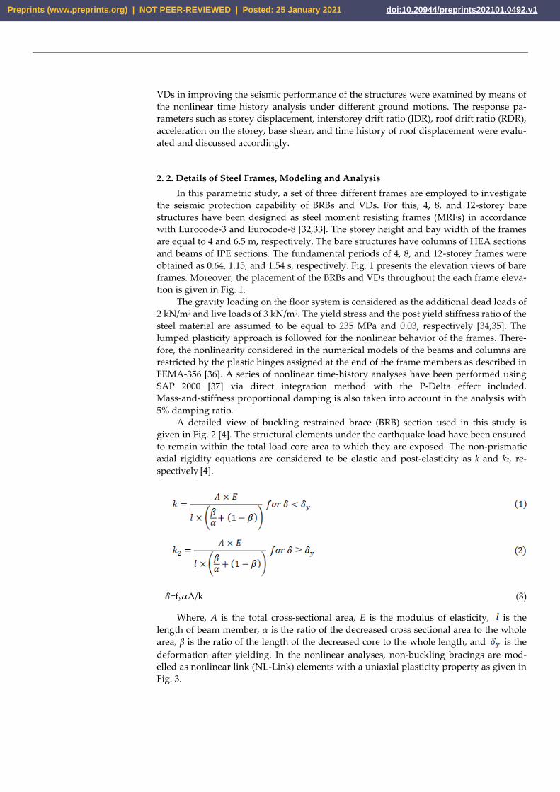
obtained as 0.64, 1.15, and 1.54 s, respectively. Fig. 1 presents the elevation views of bare
frames. Moreover, the placement of the BRBs and VDs throughout the each frame eleva-
tion is given in Fig. 1.
The gravity loading on the floor system is considered as the additional dead loads of
2 kN/m2 and live loads of 3 kN/m2. The yield stress and the post yield stiffness ratio of the
steel material are assumed to be equal to 235 MPa and 0.03, respectively [34,35]. The
lumped plasticity approach is followed for the nonlinear behavior of the frames. There-
fore, the nonlinearity considered in the numerical models of the beams and columns are
restricted by the plastic hinges assigned at the end of the frame members as described in
FEMA-356 [36]. A series of nonlinear time-history analyses have been performed using
SAP 2000 [37] via direct integration method with the P-Delta effect included.
Mass-and-stiffness proportional damping is also taken into account in the analysis with
5% damping ratio.
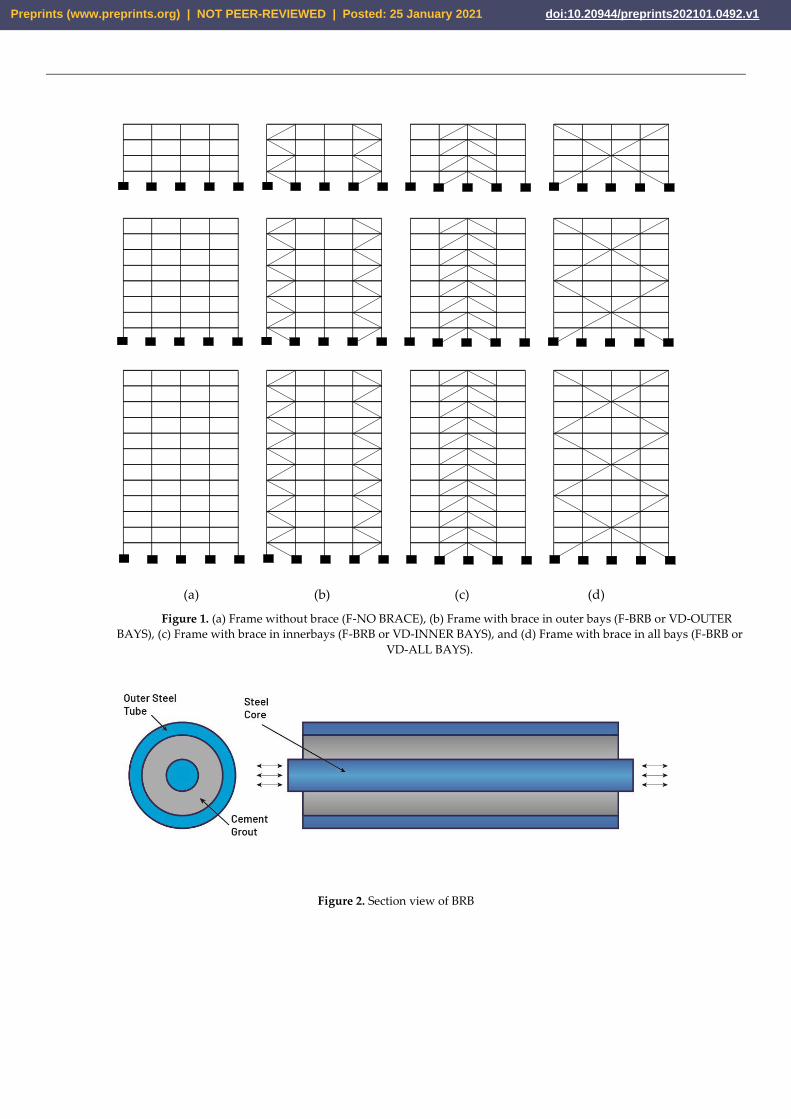
A detailed view of buckling restrained brace (BRB) section used in this study is
given in Fig. 2 [4]. The structural elements under the earthquake load have been ensured
to remain within the total load core area to which they are exposed. The non-prismatic
axial rigidity equations are considered to be elastic and post-elasticity as k and k2, re-
spectively [4].
=fyαA/k (3)
Where, A is the total cross-sectional area, E is the modulus of elasticity, is the
length of beam member, α is the ratio of the decreased cross sectional area to the whole
area, β is the ratio of the length of the decreased core to the whole length, and is the
deformation after yielding. In the nonlinear analyses, non-buckling bracings are mod-
elled as nonlinear link (NL-Link) elements with a uniaxial plasticity property as given in
Fig. 3.
Preprints (www.preprints.org) | NOT PEER-REVIEWED | Posted: 25 January 2021 doi:10.20944/preprints202101.0492.v1
(a) (b) (c) (d)
Figure 1. (a) Frame without brace (F-NO BRACE), (b) Frame with brace in outer bays (F-BRB or VD-OUTER
BAYS), (c) Frame with brace in innerbays (F-BRB or VD-INNER BAYS), and (d) Frame with brace in all bays (F-BRB or
VD-ALL BAYS).
Figure 2. Section view of BRB
Preprints (www.preprints.org) | NOT PEER-REVIEWED | Posted: 25 January 2021 doi:10.20944/preprints202101.0492.v1
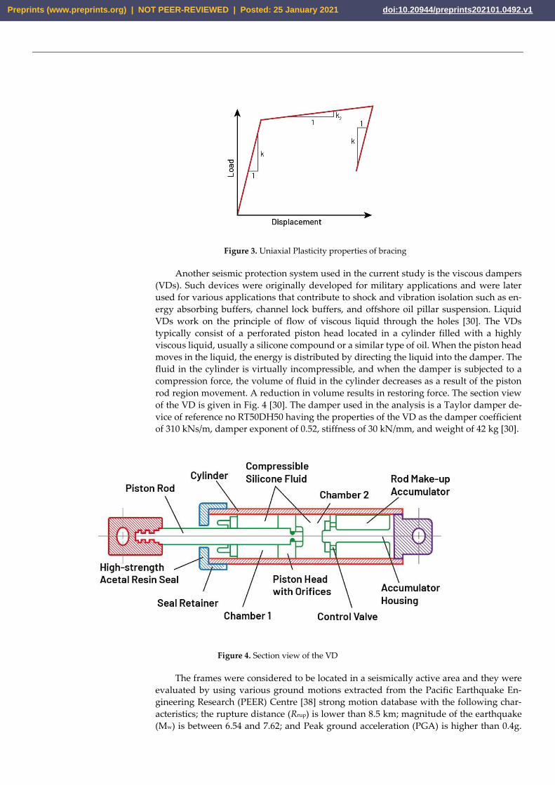
Figure 3. Uniaxial Plasticity properties of bracing
Another seismic protection system used in the current study is the viscous dampers
(VDs). Such devices were originally developed for military applications and were later
used for various applications that contribute to shock and vibration isolation such as en-
ergy absorbing buffers, channel lock buffers, and offshore oil pillar suspension. Liquid
VDs work on the principle of flow of viscous liquid through the holes [30]. The VDs
typically consist of a perforated piston head located in a cylinder filled with a highly
viscous liquid, usually a silicone compound or a similar type of oil. When the piston head
moves in the liquid, the energy is distributed by directing the liquid into the damper. The
fluid in the cylinder is virtually incompressible, and when the damper is subjected to a
compression force, the volume of fluid in the cylinder decreases as a result of the piston
rod region movement. A reduction in volume results in restoring force. The section view
of the VD is given in Fig. 4 [30]. The damper used in the analysis is a Taylor damper de-
vice of reference no RT50DH50 having the properties of the VD as the damper coefficient
of 310 kNs/m, damper exponent of 0.52, stiffness of 30 kN/mm, and weight of 42 kg [30].
Figure 4. Section view of the VD
The frames were considered to be located in a seismically active area and they were
evaluated by using various ground motions extracted from the Pacific Earthquake En-
gineering Research (PEER) Centre [38] strong motion database with the following char-
acteristics; the rupture distance (Rrup) is lower than 8.5 km; magnitude of the earthquake
(Mw) is between 6.54 and 7.62; and Peak ground acceleration (PGA) is higher than 0.4g.
Preprints (www.preprints.org) | NOT PEER-REVIEWED | Posted: 25 January 2021 doi:10.20944/preprints202101.0492.v1
The properties of the six earthquake records, namely Cape, Gazlı, Northridge, Hills,
Chi-Chi and Tabas are given in Table 1. Moreover, they were scaled based on ASCE 7-10
[39]. The frames with and without BRBs and VDs were examined by means of the non-
linear time history analysis under the given earthquakes.
Table 1. Properties of the ground motion accelerations
Name Year Mw Rjb (km) Rrup (km) Vs30 (m/s) PGA (g) PGV (cm/s)
Cape 1992 7.01 0 8.2 712.8 0.66 82.1
Gazlı 1976 6.8 3.9 5.5 659.6 0.72 65.39
Northridge 1994 6.69 0 5.3 441 0.84 122.7
Hills 1987 6.54 0.9 0.9 348.7 0.41 106.74
Chi-Chi 1999 7.62 0.6 0.6 305.9 0.82 127.8
Tabas 1978 7.35 1.8 2 766.8 0.80 118.29
Mw: Magnitude; Rjb: Distance of surface projection; Rrup: Distance of rupture; Vs30: Average shear velocity over 30 m; PGA:Peak
ground acceleration; PGV: Peak ground velocity.
3. Verification of Analytical Models
In this section, the SAP 2000 model is verified through the related experimental re-
sults. For this, the studies of Palmer et al. [40] and Christopulos [41] were utilized. They
conducted the experimental work to address the performance of BRB connections in re-
alistic framing systems and to develop a design methodology which ensures the ductility
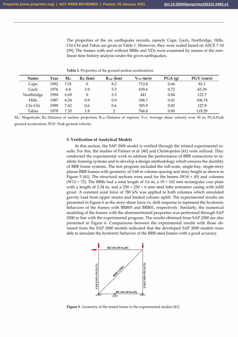
of BRB frame systems. The test program included the full-scale, single-bay, single-story
planar BRB frames with geometry of 3.68 m column spacing and story height as shown in
Figure 5 [41]. The structural sections were used for the beams (W16 × 45) and columns
(W12 × 72). The BRBs had a total length of 3.6 m, a 19 × 162 mm rectangular core plate
with a length of 2.34 m, and a 250 × 250 × 6 mm steel tube restrainer casing with infill
grout. A constant axial force of 780 kN was applied to both columns which simulated
gravity load from upper stories and limited column uplift. The experimental results are
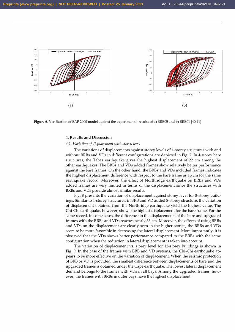
presented in Figure 6 as the story-shear force vs. drift response to represent the hysteretic
behaviors of the frames with BRB05 and BRB01, respectively. Similarly, the numerical
modeling of the frames with the aforementioned properties was performed through SAP
2000 in line with the experimental program. The results obtained from SAP 2000 are also
presented in Figure 6. Comparisons between the experimental results with those ob-
tained from the SAP 2000 models indicated that the developed SAP 2000 models were
able to simulate the hysteretic behavior of the BRB-steel frames with a good accuracy.
Figure 5. Geometry of the tested frame in the experimental studies [41]
Preprints (www.preprints.org) | NOT PEER-REVIEWED | Posted: 25 January 2021 doi:10.20944/preprints202101.0492.v1
(a)
(b)
Figure 6. Verification of SAP 2000 model against the experimental results of a) BRB05 and b) BRB01 [40,41]
4. Results and Discussion
4.1. Variation of displacement with storey level
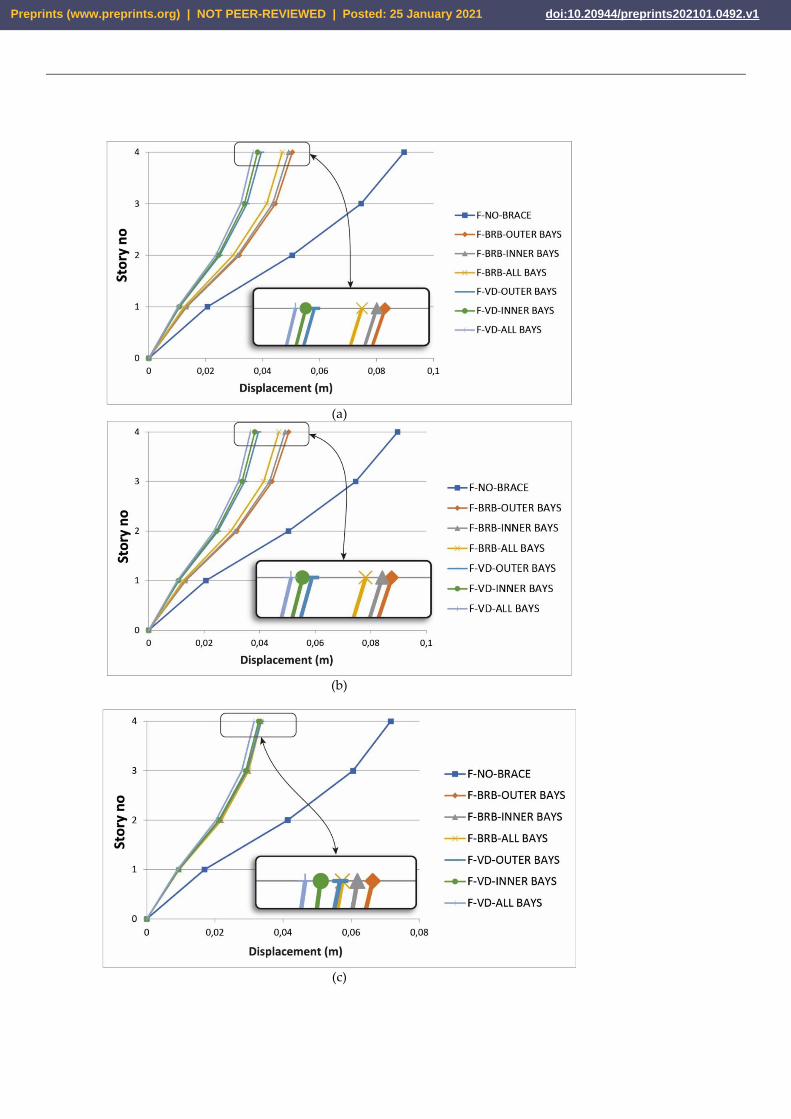
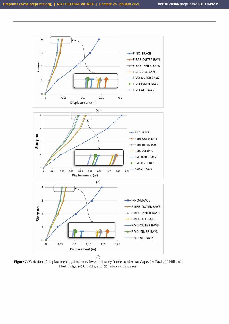
The variations of displacements against storey levels of 4-storey structures with and
without BRBs and VDs in different configurations are depicted in Fig. 7. In 4-storey bare
structures, the Tabas earthquake gives the highest displacement of 22 cm among the
other earthquakes. The BRBs and VDs added frames show relatively better performance
against the bare frames. On the other hand, the BRBs and VDs included frames indicates
the highest displacement difference with respect to the bare frame as 15 cm for the same
earthquake record. Moreover, the effect of Northridge earthquake on BRBs and VDs
added frames are very limited in terms of the displacement since the structures with
BRBs and VDs provide almost similar results.
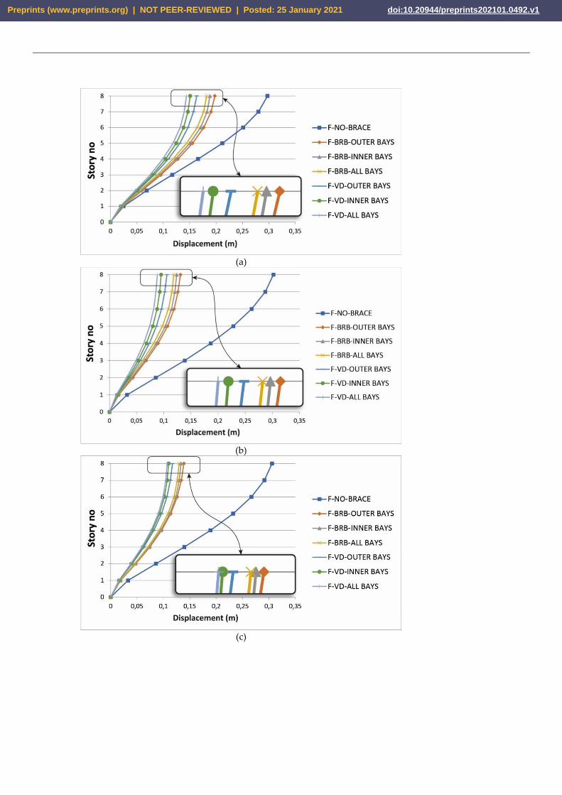
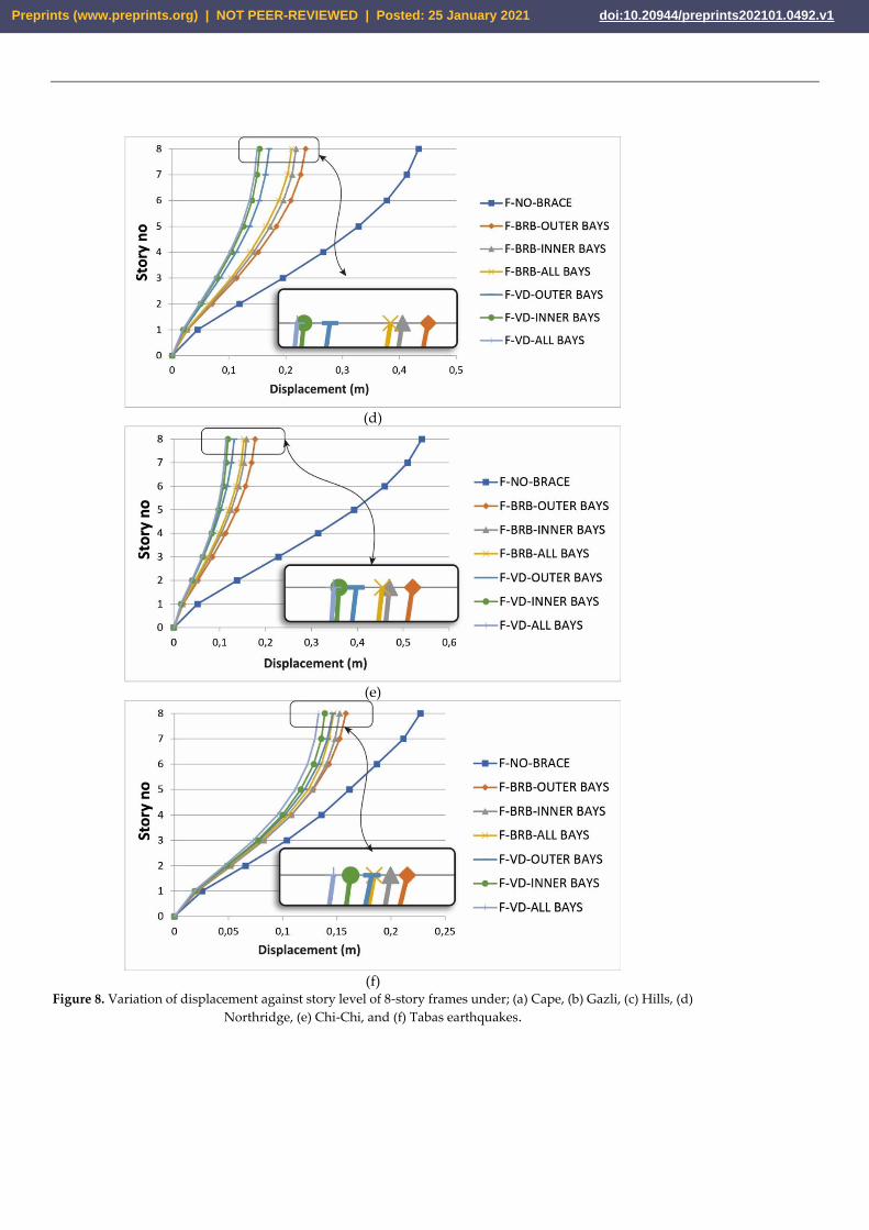
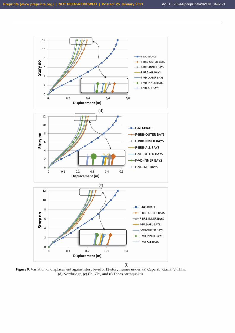
Fig. 8 presents the variation of displacement against storey level for 8-storey build-
ings. Similar to 4-storey structures, in BRB and VD added 8-storey structure, the variation
of displacement obtained from the Northridge earthquake yield the highest value. The
Chi-Chi earthquake, however, shows the highest displacement for the bare frame. For the
same record, in some cases, the difference in the displacements of the bare and upgraded
frames with the BRBs and VDs reaches nearly 35 cm. Moreover, the effects of using BRBs
and VDs on the displacement are clearly seen in the higher stories, the BRBs and VDs
seem to be more favorable in decreasing the lateral displacement. More importantly, it is
observed that the VDs shows better performance compared to the BRBs with the same
configuration when the reduction in lateral displacement is taken into account.
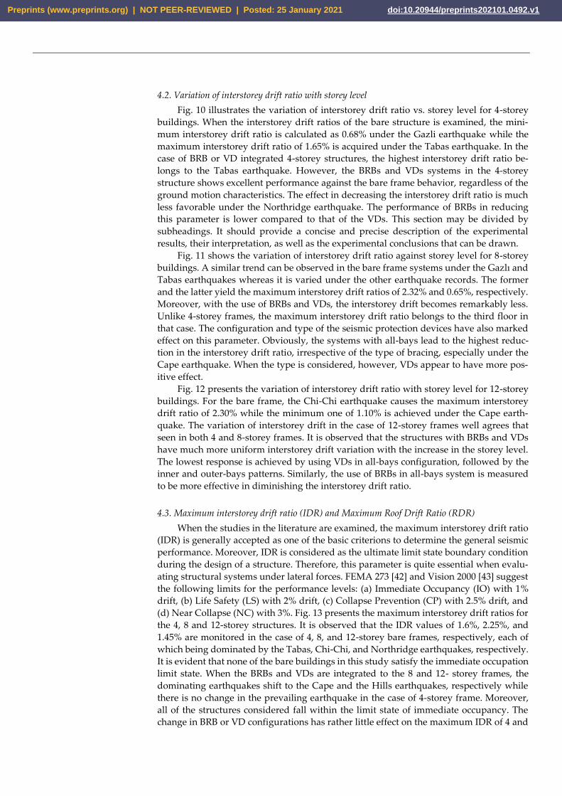
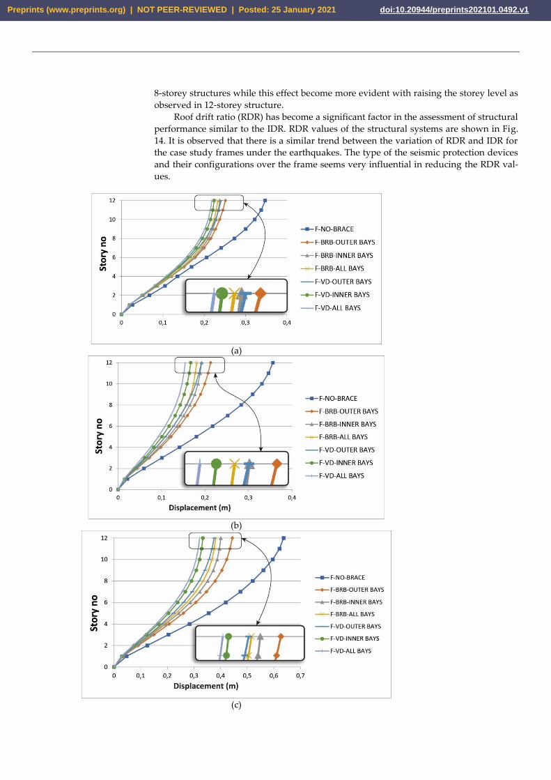
The variation of displacement vs. storey level for 12-storey buildings is shown in
Fig. 9. In the case of the frames with BRB and VD systems, the Chi-Chi earthquake ap-
pears to be more effective on the variation of displacement. When the seismic protection
of BRB or VD is provided, the smallest difference between displacements of bare and the
upgraded frames is obtained under the Cape earthquake. The lowest lateral displacement
demand belongs to the frames with VDs in all bays. Among the upgraded frames, how-
ever, the frames with BRBs in outer bays have the highest displacement.
Preprints (www.preprints.org) | NOT PEER-REVIEWED | Posted: 25 January 2021 doi:10.20944/preprints202101.0492.v1
(a)
(b)
(c)
Preprints (www.preprints.org) | NOT PEER-REVIEWED | Posted: 25 January 2021 doi:10.20944/preprints202101.0492.v1
(d)
(e)
(f)
Figure 7. Variation of displacement against story level of 4-story frames under; (a) Cape, (b) Gazli, (c) Hills, (d)
Northridge, (e) Chi-Chi, and (f) Tabas earthquakes.
Preprints (www.preprints.org) | NOT PEER-REVIEWED | Posted: 25 January 2021 doi:10.20944/preprints202101.0492.v1
(a)
(b)
(c)
Preprints (www.preprints.org) | NOT PEER-REVIEWED | Posted: 25 January 2021 doi:10.20944/preprints202101.0492.v1
(d)
(e)
(f)
Figure 8. Variation of displacement against story level of 8-story frames under; (a) Cape, (b) Gazli, (c) Hills, (d)
Northridge, (e) Chi-Chi, and (f) Tabas earthquakes.
Preprints (www.preprints.org) | NOT PEER-REVIEWED | Posted: 25 January 2021 doi:10.20944/preprints202101.0492.v1
4.2. Variation of interstorey drift ratio with storey level
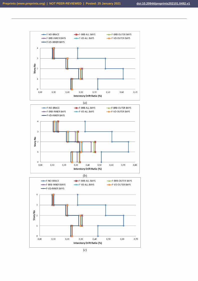
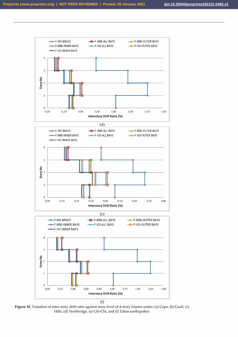
Fig. 10 illustrates the variation of interstorey drift ratio vs. storey level for 4-storey
buildings. When the interstorey drift ratios of the bare structure is examined, the mini-
mum interstorey drift ratio is calculated as 0.68% under the Gazli earthquake while the
maximum interstorey drift ratio of 1.65% is acquired under the Tabas earthquake. In the
case of BRB or VD integrated 4-storey structures, the highest interstorey drift ratio be-
longs to the Tabas earthquake. However, the BRBs and VDs systems in the 4-storey
structure shows excellent performance against the bare frame behavior, regardless of the
ground motion characteristics. The effect in decreasing the interstorey drift ratio is much
less favorable under the Northridge earthquake. The performance of BRBs in reducing
this parameter is lower compared to that of the VDs. This section may be divided by
subheadings. It should provide a concise and precise description of the experimental
results, their interpretation, as well as the experimental conclusions that can be drawn.
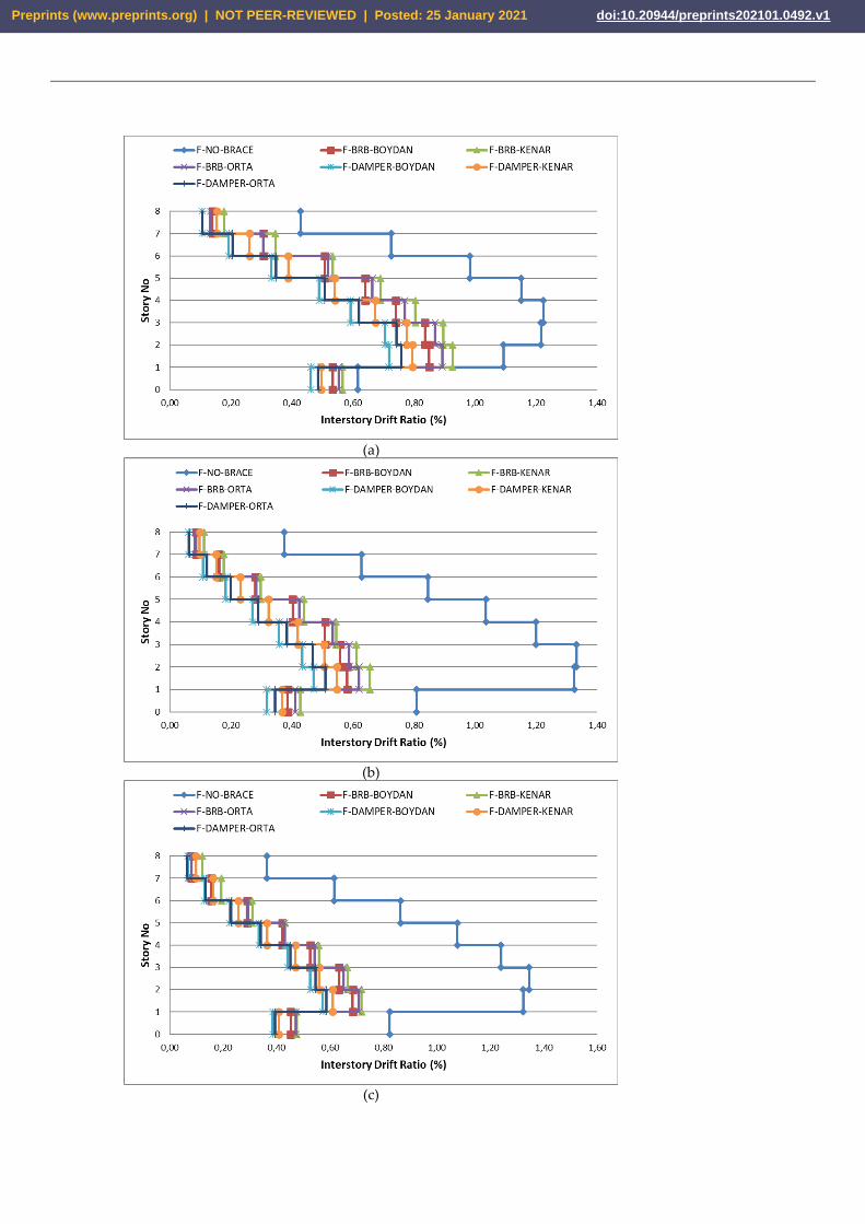
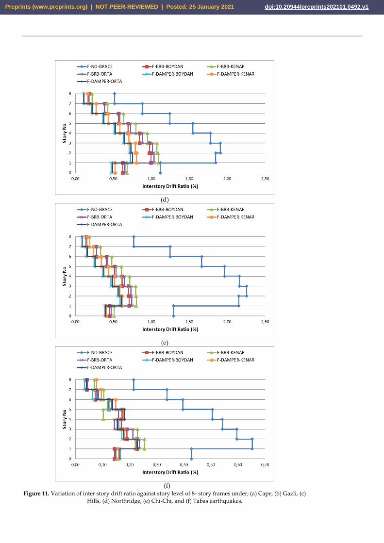
Fig. 11 shows the variation of interstorey drift ratio against storey level for 8-storey
buildings. A similar trend can be observed in the bare frame systems under the Gazlı and
Tabas earthquakes whereas it is varied under the other earthquake records. The former
and the latter yield the maximum interstorey drift ratios of 2.32% and 0.65%, respectively.
Moreover, with the use of BRBs and VDs, the interstorey drift becomes remarkably less.
Unlike 4-storey frames, the maximum interstorey drift ratio belongs to the third floor in
that case. The configuration and type of the seismic protection devices have also marked
effect on this parameter. Obviously, the systems with all-bays lead to the highest reduc-
tion in the interstorey drift ratio, irrespective of the type of bracing, especially under the
Cape earthquake. When the type is considered, however, VDs appear to have more pos-
itive effect.
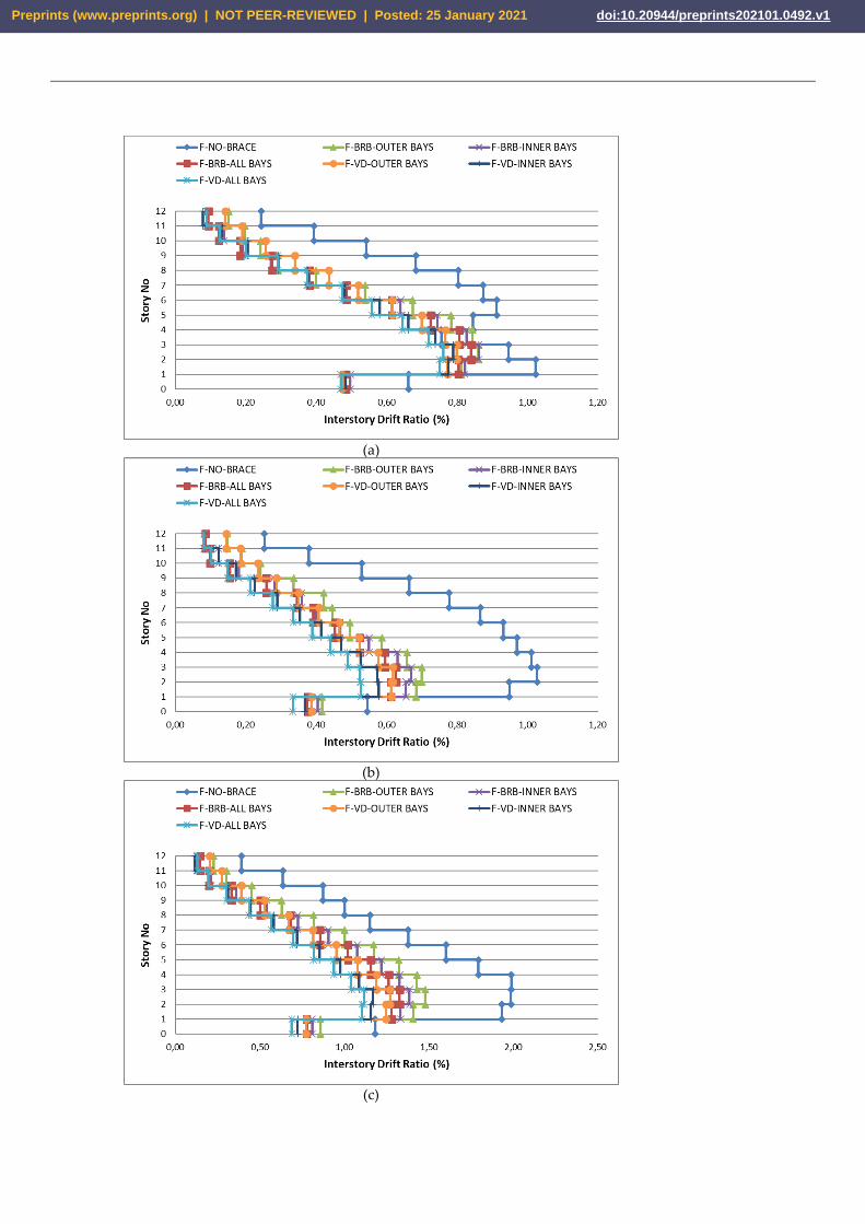
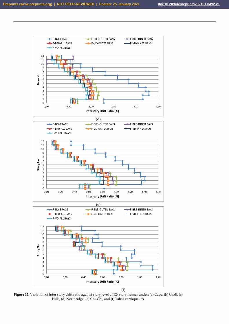
Fig. 12 presents the variation of interstorey drift ratio with storey level for 12-storey
buildings. For the bare frame, the Chi-Chi earthquake causes the maximum interstorey
drift ratio of 2.30% while the minimum one of 1.10% is achieved under the Cape earth-
quake. The variation of interstorey drift in the case of 12-storey frames well agrees that
seen in both 4 and 8-storey frames. It is observed that the structures with BRBs and VDs
have much more uniform interstorey drift variation with the increase in the storey level.
The lowest response is achieved by using VDs in all-bays configuration, followed by the
inner and outer-bays patterns. Similarly, the use of BRBs in all-bays system is measured
to be more effective in diminishing the interstorey drift ratio.
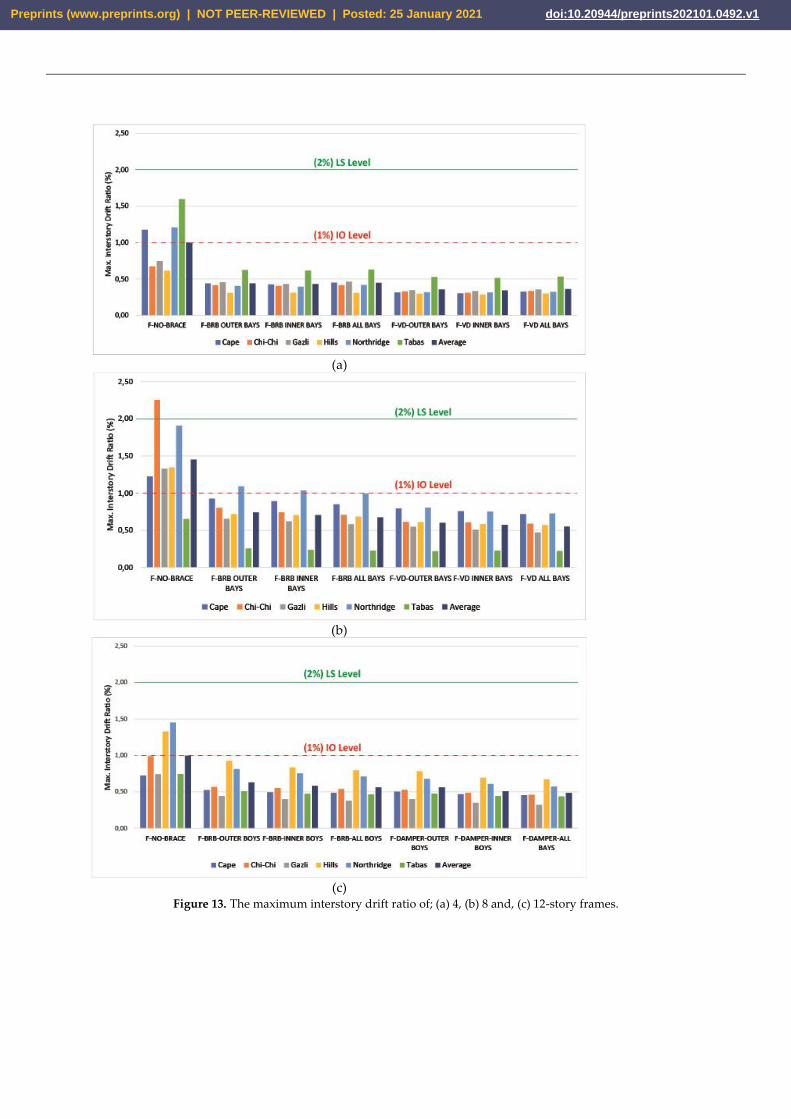
4.3. Maximum interstorey drift ratio (IDR) and Maximum Roof Drift Ratio (RDR)
When the studies in the literature are examined, the maximum interstorey drift ratio
(IDR) is generally accepted as one of the basic criterions to determine the general seismic
performance. Moreover, IDR is considered as the ultimate limit state boundary condition
during the design of a structure. Therefore, this parameter is quite essential when evalu-
ating structural systems under lateral forces. FEMA 273 [42] and Vision 2000 [43] suggest
the following limits for the performance levels: (a) Immediate Occupancy (IO) with 1%
drift, (b) Life Safety (LS) with 2% drift, (c) Collapse Prevention (CP) with 2.5% drift, and
(d) Near Collapse (NC) with 3%. Fig. 13 presents the maximum interstorey drift ratios for
the 4, 8 and 12-storey structures. It is observed that the IDR values of 1.6%, 2.25%, and
1.45% are monitored in the case of 4, 8, and 12-storey bare frames, respectively, each of
which being dominated by the Tabas, Chi-Chi, and Northridge earthquakes, respectively.
It is evident that none of the bare buildings in this study satisfy the immediate occupation
limit state. When the BRBs and VDs are integrated to the 8 and 12- storey frames, the
dominating earthquakes shift to the Cape and the Hills earthquakes, respectively while
there is no change in the prevailing earthquake in the case of 4-storey frame. Moreover,
all of the structures considered fall within the limit state of immediate occupancy. The
change in BRB or VD configurations has rather little effect on the maximum IDR of 4 and
Preprints (www.preprints.org) | NOT PEER-REVIEWED | Posted: 25 January 2021 doi:10.20944/preprints202101.0492.v1
8-storey structures while this effect become more evident with raising the storey level as
observed in 12-storey structure.
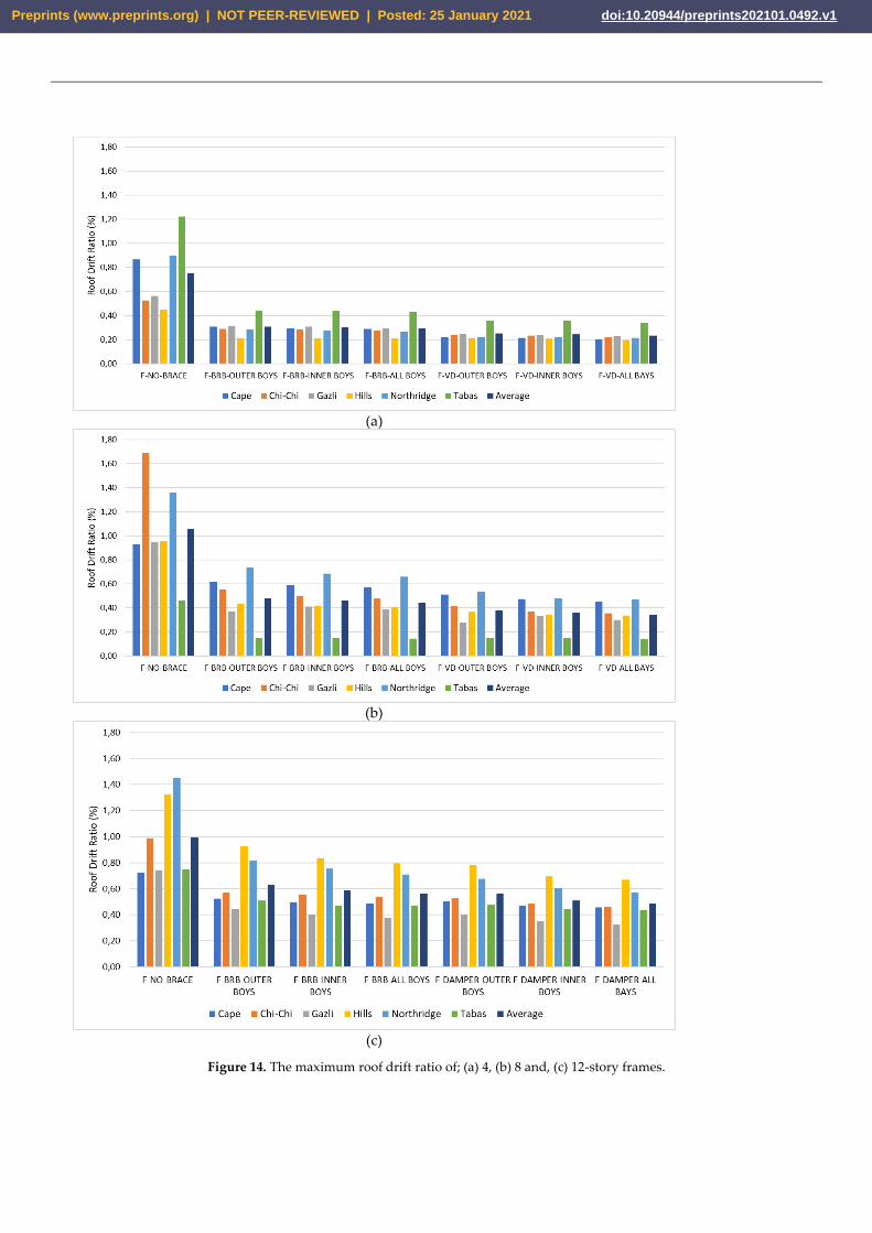
Roof drift ratio (RDR) has become a significant factor in the assessment of structural
performance similar to the IDR. RDR values of the structural systems are shown in Fig.
14. It is observed that there is a similar trend between the variation of RDR and IDR for
the case study frames under the earthquakes. The type of the seismic protection devices
and their configurations over the frame seems very influential in reducing the RDR val-
ues.
(a)
(b)
(c)
Preprints (www.preprints.org) | NOT PEER-REVIEWED | Posted: 25 January 2021 doi:10.20944/preprints202101.0492.v1
(d)
(e)
(f)
Figure 9. Variation of displacement against story level of 12-story frames under; (a) Cape, (b) Gazli, (c) Hills,
(d) Northridge, (e) Chi-Chi, and (f) Tabas earthquakes.
Preprints (www.preprints.org) | NOT PEER-REVIEWED | Posted: 25 January 2021 doi:10.20944/preprints202101.0492.v1
(a)
(b)
(c)
Preprints (www.preprints.org) | NOT PEER-REVIEWED | Posted: 25 January 2021 doi:10.20944/preprints202101.0492.v1
(d)
(e)
(f)
Figure 10. Variation of inter story drift ratio against story level of 4-story frames under; (a) Cape, (b) Gazli, (c)
Hills, (d) Northridge, (e) Chi-Chi, and (f) Tabas earthquakes.
Preprints (www.preprints.org) | NOT PEER-REVIEWED | Posted: 25 January 2021 doi:10.20944/preprints202101.0492.v1
(a)
(b)
(c)
Preprints (www.preprints.org) | NOT PEER-REVIEWED | Posted: 25 January 2021 doi:10.20944/preprints202101.0492.v1
(d)
(e)
(f)
Figure 11. Variation of inter story drift ratio against story level of 8- story frames under; (a) Cape, (b) Gazli, (c)
Hills, (d) Northridge, (e) Chi-Chi, and (f) Tabas earthquakes.
Preprints (www.preprints.org) | NOT PEER-REVIEWED | Posted: 25 January 2021 doi:10.20944/preprints202101.0492.v1
(a)
(b)
(c)
Preprints (www.preprints.org) | NOT PEER-REVIEWED | Posted: 25 January 2021 doi:10.20944/preprints202101.0492.v1
(d)
(e)
(f)
Figure 12. Variation of inter story drift ratio against story level of 12- story frames under; (a) Cape, (b) Gazli, (c)
Hills, (d) Northridge, (e) Chi-Chi, and (f) Tabas earthquakes.
Preprints (www.preprints.org) | NOT PEER-REVIEWED | Posted: 25 January 2021 doi:10.20944/preprints202101.0492.v1
(a)
(b)
(c)
Figure 13. The maximum interstory drift ratio of; (a) 4, (b) 8 and, (c) 12-story frames.
Preprints (www.preprints.org) | NOT PEER-REVIEWED | Posted: 25 January 2021 doi:10.20944/preprints202101.0492.v1
(a)
(b)
(c)
Figure 14. The maximum roof drift ratio of; (a) 4, (b) 8 and, (c) 12-story frames.
Preprints (www.preprints.org) | NOT PEER-REVIEWED | Posted: 25 January 2021 doi:10.20944/preprints202101.0492.v1
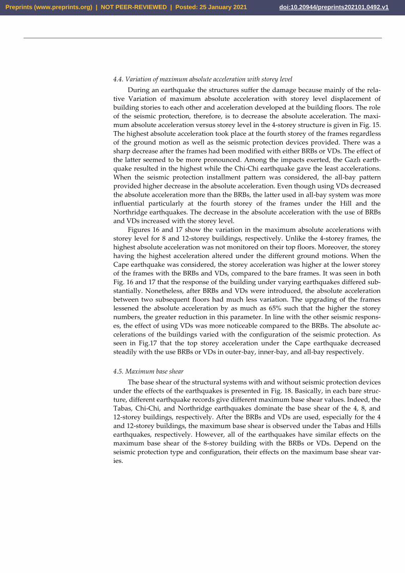
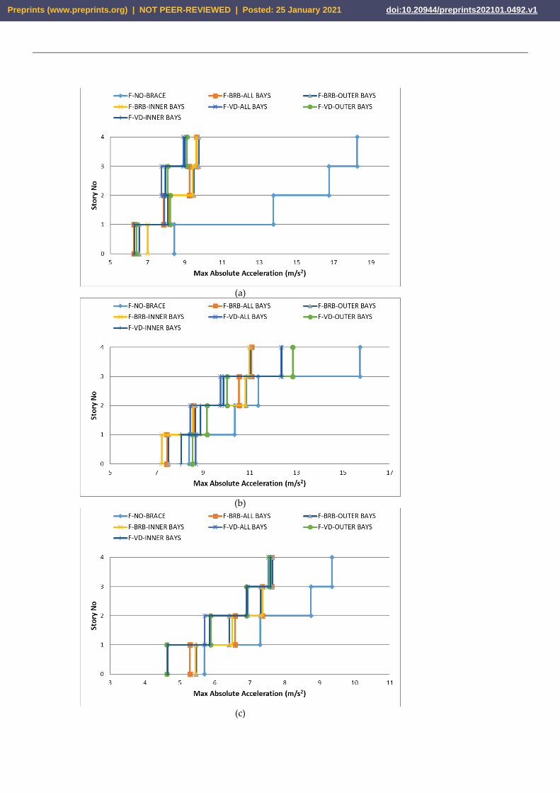
4.4. Variation of maximum absolute acceleration with storey level
During an earthquake the structures suffer the damage because mainly of the rela-
tive Variation of maximum absolute acceleration with storey level displacement of
building stories to each other and acceleration developed at the building floors. The role
of the seismic protection, therefore, is to decrease the absolute acceleration. The maxi-
mum absolute acceleration versus storey level in the 4-storey structure is given in Fig. 15.
The highest absolute acceleration took place at the fourth storey of the frames regardless
of the ground motion as well as the seismic protection devices provided. There was a
sharp decrease after the frames had been modified with either BRBs or VDs. The effect of
the latter seemed to be more pronounced. Among the impacts exerted, the Gazlı earth-
quake resulted in the highest while the Chi-Chi earthquake gave the least accelerations.
When the seismic protection installment pattern was considered, the all-bay pattern
provided higher decrease in the absolute acceleration. Even though using VDs decreased
the absolute acceleration more than the BRBs, the latter used in all-bay system was more
influential particularly at the fourth storey of the frames under the Hill and the
Northridge earthquakes. The decrease in the absolute acceleration with the use of BRBs
and VDs increased with the storey level.
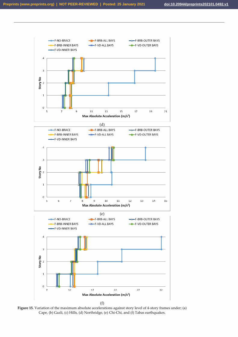
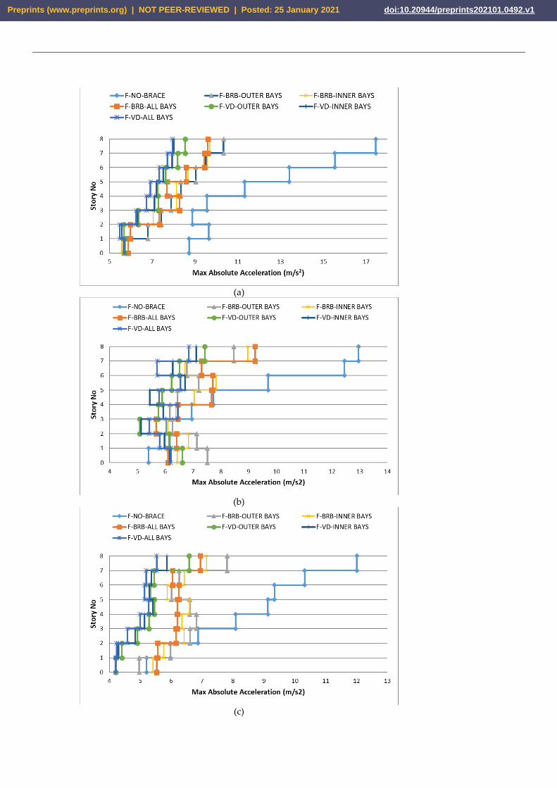
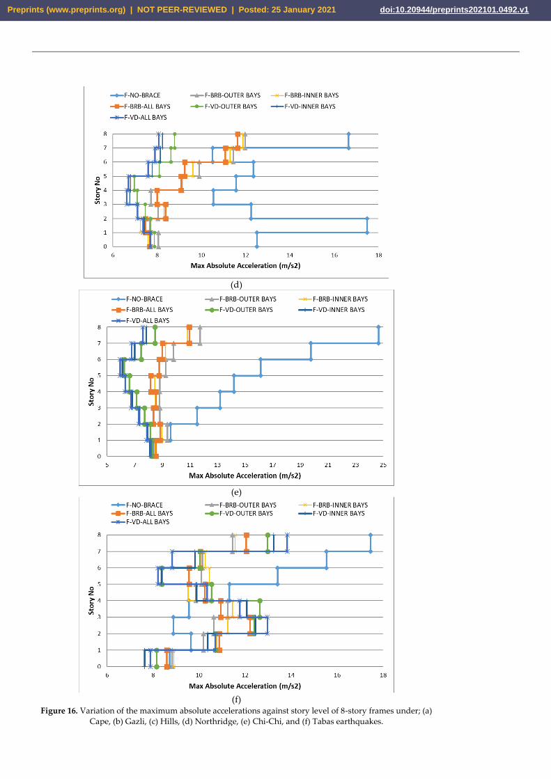
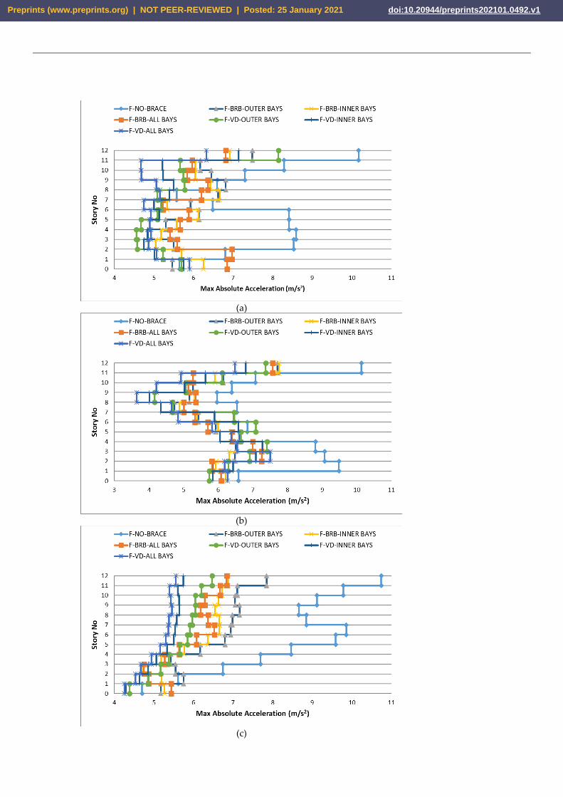
Figures 16 and 17 show the variation in the maximum absolute accelerations with
storey level for 8 and 12-storey buildings, respectively. Unlike the 4-storey frames, the
highest absolute acceleration was not monitored on their top floors. Moreover, the storey
having the highest acceleration altered under the different ground motions. When the
Cape earthquake was considered, the storey acceleration was higher at the lower storey
of the frames with the BRBs and VDs, compared to the bare frames. It was seen in both
Fig. 16 and 17 that the response of the building under varying earthquakes differed sub-
stantially. Nonetheless, after BRBs and VDs were introduced, the absolute acceleration
between two subsequent floors had much less variation. The upgrading of the frames
lessened the absolute acceleration by as much as 65% such that the higher the storey
numbers, the greater reduction in this parameter. In line with the other seismic respons-
es, the effect of using VDs was more noticeable compared to the BRBs. The absolute ac-
celerations of the buildings varied with the configuration of the seismic protection. As
seen in Fig.17 that the top storey acceleration under the Cape earthquake decreased
steadily with the use BRBs or VDs in outer-bay, inner-bay, and all-bay respectively.
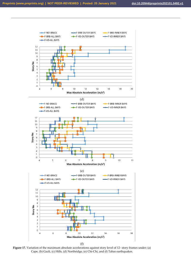
4.5. Maximum base shear
The base shear of the structural systems with and without seismic protection devices
under the effects of the earthquakes is presented in Fig. 18. Basically, in each bare struc-
ture, different earthquake records give different maximum base shear values. Indeed, the
Tabas, Chi-Chi, and Northridge earthquakes dominate the base shear of the 4, 8, and
12-storey buildings, respectively. After the BRBs and VDs are used, especially for the 4
and 12-storey buildings, the maximum base shear is observed under the Tabas and Hills
earthquakes, respectively. However, all of the earthquakes have similar effects on the
maximum base shear of the 8-storey building with the BRBs or VDs. Depend on the
seismic protection type and configuration, their effects on the maximum base shear var-
ies.
Preprints (www.preprints.org) | NOT PEER-REVIEWED | Posted: 25 January 2021 doi:10.20944/preprints202101.0492.v1
(a)
(b)
(c)
Preprints (www.preprints.org) | NOT PEER-REVIEWED | Posted: 25 January 2021 doi:10.20944/preprints202101.0492.v1
(d)
(e)
(f)
Figure 15. Variation of the maximum absolute accelerations against story level of 4-story frames under; (a)
Cape, (b) Gazli, (c) Hills, (d) Northridge, (e) Chi-Chi, and (f) Tabas earthquakes.
Preprints (www.preprints.org) | NOT PEER-REVIEWED | Posted: 25 January 2021 doi:10.20944/preprints202101.0492.v1
(a)
(b)
(c)
Preprints (www.preprints.org) | NOT PEER-REVIEWED | Posted: 25 January 2021 doi:10.20944/preprints202101.0492.v1
(d)
(e)
(f)
Figure 16. Variation of the maximum absolute accelerations against story level of 8-story frames under; (a)
Cape, (b) Gazli, (c) Hills, (d) Northridge, (e) Chi-Chi, and (f) Tabas earthquakes.
Preprints (www.preprints.org) | NOT PEER-REVIEWED | Posted: 25 January 2021 doi:10.20944/preprints202101.0492.v1
(a)
(b)
(c)
Preprints (www.preprints.org) | NOT PEER-REVIEWED | Posted: 25 January 2021 doi:10.20944/preprints202101.0492.v1
(d)
(e)
(f)
Figure 17. Variation of the maximum absolute accelerations against story level of 12- story frames under; (a)
Cape, (b) Gazli, (c) Hills, (d) Northridge, (e) Chi-Chi, and (f) Tabas earthquakes.
Preprints (www.preprints.org) | NOT PEER-REVIEWED | Posted: 25 January 2021 doi:10.20944/preprints202101.0492.v1
(a)
(b)
(c)
Figure 18. The maximum base shear of, (a) 4, (b) 8 and, (c) 12-story frames under earthquakes.
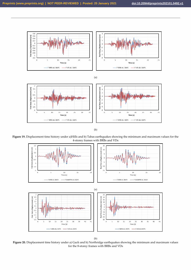
4.6. Time history of the first storey and roof displacements
Time history of the first and the roof story displacements for the 4, 8, and 12-storey
structures with BRBs and VDs placed in all-bays configurations under earthquakes
showing the minimum and the maximum values are illustrated in Figs. 19 to 21, respec-
tively. It was evident the use of VDs appears to be more effective than BRB in reducing
the displacement especially at the roof level, irrespective of the storey numbers in the
buildings. As seen in Fig. 19, the lowest displacements at the first and the roof stories of 4
story building are reported to be 1.0 and 3.3 cm as measured under the Hills earthquake.
However, the highest displacements at the first and the roof levels are 1.8 and 7.0 cm,
respectively as given by the Tabas earthquake. In the case of 8-storey buildings as seen in
Fig 20, the maximum displacement for the first and the roof story reach to 2.5 and 21.0
cm, respectively as being provided by the Northridge earthquake. Moreover, as seen in
Fig. 21, Hills earthquake yields the highest first and roof displacements of 3.0 and 39.0
cm, respectively in the case of 12-storey buildings.
Preprints (www.preprints.org) | NOT PEER-REVIEWED | Posted: 25 January 2021 doi:10.20944/preprints202101.0492.v1
(a)
(b)
Figure 19. Displacement time history under a)Hills and b) Tabas earthquakes showing the minimum and maximum values for the
4-storey frames with BRBs and VDs
(a)
(b)
Figure 20. Displacement time history under a) Gazlı and b) Northridge earthquakes showing the minimum and maximum values
for the 8-storey frames with BRBs and VDs
Preprints (www.preprints.org) | NOT PEER-REVIEWED | Posted: 25 January 2021 doi:10.20944/preprints202101.0492.v1
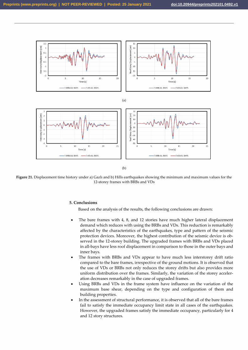
(a)
(b)
Figure 21. Displacement time history under a) Gazlı and b) Hills earthquakes showing the minimum and maximum values for the
12-storey frames with BRBs and VDs
5. Conclusions
Based on the analysis of the results, the following conclusions are drawn:
• The bare frames with 4, 8, and 12 stories have much higher lateral displacement
demand which reduces with using the BRBs and VDs. This reduction is remarkably
affected by the characteristics of the earthquakes, type and pattern of the seismic
protection devices. Moreover, the highest contribution of the seismic device is ob-
served in the 12-storey building. The upgraded frames with BRBs and VDs placed
in all-bays have less roof displacement in comparison to those in the outer bays and
inner bays.
• The frames with BRBs and VDs appear to have much less interstorey drift ratio
compared to the bare frames, irrespective of the ground motions. It is observed that
the use of VDs or BRBs not only reduces the storey drifts but also provides more
uniform distribution over the frames. Similarly, the variation of the storey acceler-
ation decreases remarkably in the case of upgraded frames.
• Using BRBs and VDs in the frame system have influence on the variation of the
maximum base shear, depending on the type and configuration of them and
building properties.
• In the assessment of structural performance, it is observed that all of the bare frames
fail to satisfy the immediate occupancy limit state in all cases of the earthquakes.
However, the upgraded frames satisfy the immediate occupancy, particularly for 4
and 12 story structures.
Preprints (www.preprints.org) | NOT PEER-REVIEWED | Posted: 25 January 2021 doi:10.20944/preprints202101.0492.v1
• Among the configurations examined in the study, BRBs or VDs in the case of the
all-bays are found to be more influential in diminishing the seismic response of the
examined structures.
Author Contributions: “Conceptualization, methodology, and validation, O.H; writing—original
draft preparation, O.H.; writing—review and editing, E.M.G.; visualization, O.H.; supervision and
project administration, E.M.G. All authors have read and agreed to the published version of the
manuscript.”
Funding: This research received no external funding.
Conflicts of Interest: The authors declare no conflict of interest.
References
1. Xie Q. State of the art of buckling-restrained braces in Asia. J Constr Steel Res 2005;61:727–48.
https://doi.org/10.1016/j.jcsr.2004.11.005.
2. Aiken ID, Kimura I. The Use of Buckling-restrained Braces in the United States 2001.
3. Sahoo DR, Chao SH. Performance-based plastic design method for buckling-restrained braced frames. Eng Struct
2010;32:2950–8. https://doi.org/10.1016/j.engstruct.2010.05.014.
4. Kumar RG, Satish Kumar SR, Kalyanaraman V. Behaviour of frames with Non-Buckling bracings under earthquake loading. J
Constr Steel Res 2007;63:254–62. https://doi.org/10.1016/j.jcsr.2006.04.012.
5. Kim J, Choi H. Behavior and design of structures with buckling-restrained braces. Eng Struct 2004;26:693–706.
https://doi.org/10.1016/j.engstruct.2003.09.010.
6. AISC (2005). seismic provisions for structural steel buildings, American institute of steel construction, Inc., Chicago, IL. AISC
(2005b).
7. Asgarian, B. and Amirhesari, N. (2008). Comparison of dynamic nonlinear behavior of ordinary and buckling restrained
braced frames subjected to strong ground motion. The Structural Design of Tall and Special Buildings, 17(2), 367- 386.
8. Apostolakis, G.; Dargush, G.F. Optimal seismic design of moment-resisting steel frames with hysteretic passive devices.
Earthquake Engng Struct. Dyn 2010, 39, 355-376.
9. César, M.B.; Coelho, J.P.; Gonçalves, J. (2019) Semi-active vibration control of a non-collocated civil structure using evolution-
ary-based belbic. Actuators, 8, 1-19.
10. Ghanchi, N.; Kewate, S. Dynamic analysis of 25 storey RCC building with and without viscous dampers. Int J of Sci Eng Res
2015, 6, 63-68.
11. Celik OC, Berman JW, Bruneau M. Cyclic testing of braces laterally restrained by steel Studs. J Struct Eng 2005;131:1114–24.
https://doi.org/10.1061/(ASCE)0733-9445(2005)131:7(1114).
12. Lin PC, Takeuchi T, Matsui R. Seismic performance evaluation of single damped-outrigger system incorporating buck-
ling-restrained braces. Earthq Eng Struct Dyn 2018;47:2343–65. https://doi.org/10.1002/eqe.3072.
13. Dicleli M, Mehta A. Seismic performance of chevron braced steel frames with and without viscous fluid dampers as a function
of ground motion and damper characteristics. J Constr Steel Res 2007;63:1102–15. https://doi.org/10.1016/j.jcsr.2006.09.005.
14. Wang H, Feng Y, Wu J, Jiang Q, Chong X. Damage Concentration Effect of Multistory Buckling-Restrained Braced Frames.
Adv Civ Eng 2019;2019. https://doi.org/10.1155/2019/7164373.
15. Sabelli R, Mahin S, Chang C. Seismic demands on steel braced frame buildings with buckling-restrained braces. Eng Struct
2003;25:655–66. https://doi.org/10.1016/S0141-0296(02)00175-X.
16. Tremblay R, Bolduc P, Neville R, DeVall R. Seismic testing and performance of buckling-restrained bracing systems. Can J Civ
Eng 2006;33:183–98. https://doi.org/10.1139/l05-103.
17. Hao H. Performance of Non-Buckling Segmented Brace Members for Mitigating Seismic Responses of Frame Structures 2014.
18. S.Karimi, F.Arbabi. Seismic Evaluation and Cyclic Testing Of Buckling Restrained Braces Manufactured In Iran. 14th World
Conf Earthq Eng 2008.
19. Tremblay R, Filiatrault A. Seismic impact loading in inelastic tension-only concentrically braced steel frames: Myth or reality?
Earthq Eng Struct Dyn 1996;25:1373–89. https://doi.org/10.1002/(SICI)1096-9845(199612)25:12<1373::AID-EQE615>3.0.CO;2-Y.
Preprints (www.preprints.org) | NOT PEER-REVIEWED | Posted: 25 January 2021 doi:10.20944/preprints202101.0492.v1
20. Hussain S, Van Benschoten P, Al Satari M, Lin S. Buckling Restrained Braced Frame (BRBF) Structures: Analysis, Design and
Approvals Issues. 75th SEAOC Annu Conv Sept 13-16 2006.
21. Lin KC, Lin CCJ, Chen JY, Chang HY. (2010). Seismic reliability of steel framed buildings, Structural Safety; 32(3):174–182.
22. Deulkar W. N., Modhera C. D. and Patil H S (2010). Buckling restrained braces for vibration control of building structure.
International Journal of Research and Reviews in Applied Sciences, 4, 363-372.
23. Di Sarno, L. and Manfredi, G. (2010). Seismic Response of Reinforced Concrete Buildings Retrofitted with Dissipative Steel
Braces. Journal of Civil Engineering and Architecture, ISSN 1934-7359, USA, 4, No.2 (Serial No.27).
24. Symans MD, Charney FA, Whittaker AS, Constantinou MC, Kircher CA, Johnson MW, et al. Energy dissipation systems for
seismic applications: Current practice and recent developments. J Struct Eng 2008;134:3–21.
https://doi.org/10.1061/(ASCE)0733-9445(2008)134:1(3).
25. Crewe A. Passive energy dissipation systems in structural engineering. Struct Saf 1998;20:197–8.
https://doi.org/10.1016/s0167-4730(97)00034-9.
26. Chang KC, Chen SJ, Lai ML. Inelastic behavior of steel frames with added viscoelastic dampers. J Struct Eng 1996;122:1178–86.
https://doi.org/10.1061/(ASCE)0733-9445(1996)122:10(1178).
27. Xu ZD. Earthquake mitigation study on viscoelastic dampers for reinforced concrete structures. JVC/Journal Vib Control
2007;13:29–43. https://doi.org/10.1177/1077546306068058.
28. Xu ZD, Wang DX, Shi CF. Model, tests and application design for viscoelastic dampers. JVC/Journal Vib Control
2011;17:1359–70. https://doi.org/10.1177/1077546310373617.
29. SaiChethan, K.; Sirinivas, K.S.; Ranjitha, K.P. Seismic performance evaluation of fluid viscous dampers. Int J of Res in Eng Tech
2017, 06, 27-32.
30. Prasad, M.L.A. and Mazumder, E.A. Use of viscous damper as an energy dissipative device in steel structures. Int J of Me-
chanical and Prod Eng 2016;4:54-66.
31. Balkanlou, V.S.; Karimi, M.R.B.; Azar, B.B.; (2013) Behravesh, A. Evaluating effects of viscous dampers on optimizing seismic
behavior of structures. Int J Current Eng Tec, 3, 1150-1157.
32. Eurocode 3. Design of steel structures. Part 1.1: General rules and rules for buildings. Brussels (Belgium): European Commu-
nities for Standardisation; 2004.
33. Eurocode 8. Design provisions for earthquake resistance of structures. Part 1.3: General rules. Specific rules for various mate-
rials and elements. Brussels (Belgium): European Communities for Standardisation; 2004.
34. Karavasilis TL, Bazeos N, Beskos DE. Maximum displacement profiles for the performance based seismic design of plane steel
moment resisting frames. Eng Struct 2006;28(1):9–22.
35. Deringol AH, Güneyisi EM. Effect of friction pendulum bearing properties on behaviour of buildings subjected to seismic
loads. Soil Dynamics and Earthquake Eng 2019; 125:1-20
36. FEMA-356, ASCE- American Society of Civil Engineers. Prestandard and Commentary for the Seismic Rehabilitation of
Buildings. Rehabil Requir 2000:1–518.
37. SAP 2000 Advanced Structural Analysis Program, Version 12 2010.
38. PEERC. The pacific earthquake engineering research center. User's manual for the PEER ground motion database application.
Berkeley: University of California; 2011.
39. American Society of Civil Engineers, ASCE. Minimum design loads for buildings and other structures. ASCE/SEI 7-10, Reston,
VA. 2010.
40. Palmer KD, Christopulos AS, Lehman DE, Roeder CW. Experimental evaluation of cyclically loaded, large-scale, planar and
3-d buckling-restrained braced frames. J Constr Steel Res 2014;101:415-425.
41. Christopulos AS. Improved Seismic Performance of Buckling Restrained Braced Frames. MSc thesis, University of Washing-
ton, DC (2005)
42. FEMA 273, N.Guidelines for the Seismic Rehabilitation of Buildings. Federal Emergency Management Agency Washington,
DC (1997)
43. Vision 2000, Conceptual Framework for Performance Based Seismic Engineering of Buildings. Structual Engineers Association
of California. 2 (1995)
Preprints (www.preprints.org) | NOT PEER-REVIEWED | Posted: 25 January 2021 doi:10.20944/preprints202101.0492.v1